JP4394828B2 - Ultrasound blood vessel image forming apparatus and operating method thereof - Google Patents
Ultrasound blood vessel image forming apparatus and operating method thereofDownload PDFInfo
- Publication number
- JP4394828B2 JP4394828B2JP2000513125AJP2000513125AJP4394828B2JP 4394828 B2JP4394828 B2JP 4394828B2JP 2000513125 AJP2000513125 AJP 2000513125AJP 2000513125 AJP2000513125 AJP 2000513125AJP 4394828 B2JP4394828 B2JP 4394828B2
- Authority
- JP
- Japan
- Prior art keywords
- frequency
- transducer
- blood
- intensity
- luminance intensity
- Prior art date
- Legal status (The legal status is an assumption and is not a legal conclusion. Google has not performed a legal analysis and makes no representation as to the accuracy of the status listed.)
- Expired - Lifetime
Links
Images


Classifications
- G—PHYSICS
- G01—MEASURING; TESTING
- G01S—RADIO DIRECTION-FINDING; RADIO NAVIGATION; DETERMINING DISTANCE OR VELOCITY BY USE OF RADIO WAVES; LOCATING OR PRESENCE-DETECTING BY USE OF THE REFLECTION OR RERADIATION OF RADIO WAVES; ANALOGOUS ARRANGEMENTS USING OTHER WAVES
- G01S7/00—Details of systems according to groups G01S13/00, G01S15/00, G01S17/00
- G01S7/52—Details of systems according to groups G01S13/00, G01S15/00, G01S17/00 of systems according to group G01S15/00
- G01S7/52017—Details of systems according to groups G01S13/00, G01S15/00, G01S17/00 of systems according to group G01S15/00 particularly adapted to short-range imaging
- G01S7/52023—Details of receivers
- G01S7/52036—Details of receivers using analysis of echo signal for target characterisation
- A—HUMAN NECESSITIES
- A61—MEDICAL OR VETERINARY SCIENCE; HYGIENE
- A61B—DIAGNOSIS; SURGERY; IDENTIFICATION
- A61B8/00—Diagnosis using ultrasonic, sonic or infrasonic waves
- A61B8/12—Diagnosis using ultrasonic, sonic or infrasonic waves in body cavities or body tracts, e.g. by using catheters
- G—PHYSICS
- G01—MEASURING; TESTING
- G01S—RADIO DIRECTION-FINDING; RADIO NAVIGATION; DETERMINING DISTANCE OR VELOCITY BY USE OF RADIO WAVES; LOCATING OR PRESENCE-DETECTING BY USE OF THE REFLECTION OR RERADIATION OF RADIO WAVES; ANALOGOUS ARRANGEMENTS USING OTHER WAVES
- G01S15/00—Systems using the reflection or reradiation of acoustic waves, e.g. sonar systems
- G01S15/88—Sonar systems specially adapted for specific applications
- G01S15/89—Sonar systems specially adapted for specific applications for mapping or imaging
- G01S15/8906—Short-range imaging systems; Acoustic microscope systems using pulse-echo techniques
- G01S15/895—Short-range imaging systems; Acoustic microscope systems using pulse-echo techniques characterised by the transmitted frequency spectrum
- G—PHYSICS
- G01—MEASURING; TESTING
- G01S—RADIO DIRECTION-FINDING; RADIO NAVIGATION; DETERMINING DISTANCE OR VELOCITY BY USE OF RADIO WAVES; LOCATING OR PRESENCE-DETECTING BY USE OF THE REFLECTION OR RERADIATION OF RADIO WAVES; ANALOGOUS ARRANGEMENTS USING OTHER WAVES
- G01S15/00—Systems using the reflection or reradiation of acoustic waves, e.g. sonar systems
- G01S15/88—Sonar systems specially adapted for specific applications
- G01S15/89—Sonar systems specially adapted for specific applications for mapping or imaging
- G01S15/8906—Short-range imaging systems; Acoustic microscope systems using pulse-echo techniques
- G01S15/8979—Combined Doppler and pulse-echo imaging systems
- G—PHYSICS
- G01—MEASURING; TESTING
- G01S—RADIO DIRECTION-FINDING; RADIO NAVIGATION; DETERMINING DISTANCE OR VELOCITY BY USE OF RADIO WAVES; LOCATING OR PRESENCE-DETECTING BY USE OF THE REFLECTION OR RERADIATION OF RADIO WAVES; ANALOGOUS ARRANGEMENTS USING OTHER WAVES
- G01S7/00—Details of systems according to groups G01S13/00, G01S15/00, G01S17/00
- G01S7/52—Details of systems according to groups G01S13/00, G01S15/00, G01S17/00 of systems according to group G01S15/00
- G01S7/52017—Details of systems according to groups G01S13/00, G01S15/00, G01S17/00 of systems according to group G01S15/00 particularly adapted to short-range imaging
- G01S7/52046—Techniques for image enhancement involving transmitter or receiver
Landscapes
- Engineering & Computer Science (AREA)
- Physics & Mathematics (AREA)
- Remote Sensing (AREA)
- Radar, Positioning & Navigation (AREA)
- Acoustics & Sound (AREA)
- General Physics & Mathematics (AREA)
- Computer Networks & Wireless Communication (AREA)
- Health & Medical Sciences (AREA)
- Life Sciences & Earth Sciences (AREA)
- Medical Informatics (AREA)
- Veterinary Medicine (AREA)
- Molecular Biology (AREA)
- Surgery (AREA)
- Animal Behavior & Ethology (AREA)
- General Health & Medical Sciences (AREA)
- Public Health (AREA)
- Heart & Thoracic Surgery (AREA)
- Biomedical Technology (AREA)
- Radiology & Medical Imaging (AREA)
- Pathology (AREA)
- Nuclear Medicine, Radiotherapy & Molecular Imaging (AREA)
- Biophysics (AREA)
- Ultra Sonic Daignosis Equipment (AREA)
Description
Translated fromJapanese【0001】
(発明の背景)
本発明は、高解像度の血管内像形成に関し、より詳しくは、血管内超音波像形成と画像品質を向上させる技術に関する。
【0002】
腔内又は血管内超音波(IVUSとも言われる)像形成において、脈管壁構造を高解像度で像形成するのは、高い超音波周波数で像形成する必要がある。ある種類の腔内システムでは、血管内に配置したカテーテルプローブ内に一方向性の超音波励振器/検出器を使用し、血管内部から放射された超音波エネルギーによるエコーから信号データを収集する。特に、カテーテル内でトランスデューサから集束した超音波圧力波を放射方向に送り、ターゲット領域からのエコーを同じトランスデューサで集めることにより、ベクトルを作成する。回転したトランスデューサからの多数の放射ベクトルにより、画像フレームができる。1つのプロセッサが、収集したデータに画像処理(例えば、移動画像の安定化、血液スペックルの一時的濾波、及び他の画像向上技術)を行い、ラスター走査表示モニター上に、修正し濾波した血管内画像の表示を提供する。
【0003】
広い周波数範囲(例えば、5MHzから50MHz)で、特にある用途ではより高い超音波周波数で像形成するのが好ましい。しかし、高周波数の血管内超音波像形成では、このような画像の血球からの後方散乱が重大な問題である。血球からの超音波の散乱は周波数の4乗に比例し、超音波の周波数が高いほど、血液からの後方散乱はより多いからである。その結果、血液分子からのエコーは、管腔−脈管壁のコントラストが低下し、好ましくない。脈管の狭くなっている程度を確かめ、プラークの空間的広がりを求めるため、血液/組織の境界を決める必要があるからである。それゆえ、画像表示を向上させるには、血液からの後方散乱による超音波画像のエコー(血液からの後方散乱の不規則なパターンは、「血液スペックル」といわれる)を検出する必要がある。いったん検出されると、血液スペックルは除去、又は血液から壁構造を区別できるレベルまで抑制することが出来、又は血液に異なる表示色を与えることで区別でき、及び/又は血液/組織の境界をよりよく線引きするのに使用することが出来る。
【0004】
血管内超音波像形成において、画像の血液スペックルを検出するのに色々の技術が使用されてきた。これらの技術は、血液と組織を区別するのに有用とは限らない。いつも真実とは限らない重要な仮定に基づいているからである。幾つかの技術は、血液と組織を区別するため、血液からのエネルギー散乱強度は、組織からの散乱強度と比較して低いという仮定に基づいている。他の技術は、血液は組織と比較してずっと速く動き、組織とはドップラー信号が異なるという仮定に基づく。しかし、実施には、このような仮定に反する場合がある。特に、血液から散乱するエネルギーは、組織からの散乱と同じくらい明るい場合があり、及び/又は血液は非常にゆっくり動き又は全く動かないこともある。これらの技術は、全般的には有効であるが、これらの仮定が当てはまらない状況では、それほど有効ではない。
上述のことから、血液のスペックルを検出し、腔内の超音波画像の表示から血液に誘導されたエコーをなくすか、又ははっきりと識別できるようにする代替の又は補助的な方法と装置が必要である。
【0005】
(発明の概要)
本発明は、血液のスペックルを検出する改善された方法と装置を提供する。本発明は、血液からのエネルギー散乱強度は、高い周波数依存性を示すが、組織からの散乱強度は、強い周波数依存性がないという事実を利用する。特定の実施例では、本発明は、特に、血液の散乱強度が組織の散乱強度と近く、及び/又は血液がゆっくり動くか又は全く動かない状況で、血管内超音波像形成における血液スペックルの問題を扱う、特に簡単で有用な解法を提供する。
【0006】
特定の実施例によれば、本発明は、血管内の超音波血管画像の血液スペックルを検出する方法を提供する。この方法は、血管内のターゲットに超音波RFエネルギーを照射して、血管内のターゲットから超音波エコーを生成し、血管内のターゲットからの超音波エコーを、受信したRF信号に変換するステップを備える。この方法はまた、受信したRF信号の少なくとも一部のスペクトル解析を行い、受信したRF信号のスペクトルの強度情報を提供することを備える。強度情報には、スペクトル内の高周波数における第1輝度強度と、スペクトル内の低周波数における第2輝度強度とが含まれる。この方法は、さらに第1輝度強度と第2輝度強度とを比較し、第1輝度強度と第2輝度強度がほぼ等しければ、血管内のターゲットは組織であると求め、第1輝度強度が第2輝度強度より大きければ、血管内のターゲットは血液であると求める。この求めるステップは、高周波数と低周波数の強度感度を考慮に入れる。幾つかの特定の実施例では、完全なフーリエ解析により、又は高周波数と低周波数について濾波することにより、スペクトル解析を行う。
【0007】
他の特定の実施例では、本発明は、血管内の超音波血管画像の血液スペックルを検出する方法を提供する。この方法は、血管内のターゲットに第1周波数の超音波RFエネルギーを照射し、血管内のターゲットから超音波エコーを生成して、第1画像フレームを形成し、血管内のターゲットに第2周波数の超音波RFエネルギーを照射し、前記血管内のターゲットから超音波エコーを生成して、第2画像フレームを形成するステップを備える。第1と第2画像フレームは、時間が連続し、第1、第2周波数の一方は低周波数で、他方は高周波数である。この方法は、また第1と第2画像フレームを減算し、減算した画像を得るステップと、減算した画像フレームのほぼ相殺された部分は組織であり、減算した画像フレームの相殺されない部分は血液であると求めるステップを備える。この求めるステップは、高周波数と低周波数の強度感度を考慮に入れる。
【0008】
更に他の特定の実施例によれば、本発明は、超音波血管像形成システムの装置を提供する。この装置は、第1と第2周波数において、既知で十分な強度感度の周波数帯域幅を有するトランスデューサを備える。トランスデューサは、第1と第2周波数で発信された超音波を使用して、血管内のターゲットからエコーを得て、血管内の画像を形成する。第1と第2周波数は、トランスデューサのピーク出力より3dB低い中心周波数より下の周波数とピーク出力より3dB低い中心周波数より上の周波数の間である。この装置は、また信号処理デバイスと、コンピュータで読取り可能な媒体を備える。信号処理デバイスは、トランスデューサとディスプレーに結合し、血管内画像を表示することが出来る。コンピュータで読取り可能な媒体は、信号処理デバイスに読取られるように結合し、コンピュータで読取り可能なプログラムを記憶し、これにより第1周波数の超音波からのエコーの第1輝度強度を、第2周波数の超音波からのエコーの第2輝度強度と比較し、血管内画像の血液スペックルを検出する。
【0009】
本発明のこれらの及び他の実施例、その利点と態様を、以下に詳細な説明と図面に関連して説明する。
【0010】
(特定の実施例の説明)
本発明は、血管内超音波像形成システムにおいて、血液と組織を正確に識別する向上した画像処理を提供する。本発明は、特定の実施例によれば、スペクトル解析を使用して、血液を組織から区別しても良い。特に本発明は、血液(即ち、血球は、厚さ約2μm、直径約7μmで、超音波エネルギーの波長よりずっと小さい粒子である)からのエネルギー散乱強度は、高い周波数依存性を示すが、組織からの散乱強度は、強い周波数依存性がないという事実を利用する。即ち、血液による散乱では、より高い周波数での散乱強度は、より低い周波数での散乱強度よりずっと強い。スペクトルにより周波数依存性が存在することの情報を得られるので、スペクトルを調べると、反射物の大きさに関する情報が得られ、反射物が血液か又は組織であるかを示す。
【0011】
本発明は、図1Aに示す血管内超音波像形成システムに関連して使用する画像処理方法を提供する。図1Aを参照すると、本発明による血管内画像表示に使用できる血管内超音波像形成システム10の1つの種類のブロック線図が示される。図1Aに示すように、特殊信号処理デバイス10が、カテーテルプローブ13を含む超音波像形成システム12と共に使用され、超音波ビーム14が超音波送信機即ち励振器16により放射される。例えば5MHzから50MHzの超音波信号14が、血管内のターゲットに向けて送られ、血液を含む血管内の構造から超音波エコー信号18の形の反射をひき起こす。情報の放射スポーク即ちベクトル18が、超音波反射に基づいて、ターゲット20(血管の内壁)から、トランスデューサ22で集められる。特に、情報は、血管20内のカテーテル13内で回転(角度θ)された励振器16から狭い超音波サンプリングビーム14を発射することにより、採集される。ある範囲の振幅の反射スケールは、トランスデューサ22により、振幅として、各ベクトルの半径に沿った単位距離(r)の関数として記録される。本発明の特定の実施例によれば、カテーテル13から放射状に向けられた合計で例えば256のスポークで、画像フレームのデータを得て、情報を処理すれば十分である。この画像データ収集により、利用する特定のシステムによって、アナログ又はデジタル情報の何れかが得られる。
【0012】
収集したデータは、走査した(掃引、又は回転)2次元画像の点を表す画素に変換され、例えば、黒と白の間のグレースケール上の値を割当てられる。もちろん、他の実施例では色を割当てることも出来る。この画像が、図1Aに示すように、血管20の構造の断面「スライス」を表し、壁構造(血管壁界面)26と、血液(血液領域)24の管腔を含む。より詳しくは、血管内超音波像形成システムが画像データを得た後、信号プロセッサ10は、収集した画像データの信号処理を実行する。画像データを、走査、変換してx−yラスタ走査した画像データとして、表示メモリー32に記憶出来るようにし、次にラスタ走査した画像データをフレーム毎に安定化してラスタ画像を提供し、信号プロセッサ10に結合した表示デバイス30で見られるようにする。信号プロセッサ10はまた、後述するように、本発明の特定の実施例を実行するため、コンピュータで読取り可能なプログラムを記憶するのに使用するプログラムメモリー38を備えても良い。又は、本発明の特定の実施例を実行するためのコンピュータで読取り可能なプログラムは、信号プロセッサ10に結合したメモリーに記憶しても良い。例えば、メモリーは、読み出し専用メモリー、固定ディスクドライブ、又は取外し可能ディスクドライブでも良い。本発明を使用して、表示された画像の血液スペックルを識別、又は抑制/除去することが出来る。
【0013】
本発明の特定の実施例によれば、エコーのラジオ周波数(RF)が収集され、次に、業界で良く知られているように、スペクトルを解析するのにフーリエ解析を使用して周波数ドメインで解析される。図2は、スペクトル全体を解析する特定の実施例を例示する簡単化した図である。RFエコーを収集するための装置の電子装置は、反射したエコーの対数圧縮した包絡線を得るアプローチで使用する装置と比較して、より高い周波数を扱う必要があり、より高いダイナミックレンジを有する。この特定の実施例によれば、トランスデューサは、その全帯域幅でRFを送信し(ステップ51で示す)、RFエコー信号を受信する(ステップ55)。フーリエ解析を使用して計算し(ステップ59)、RFエコー信号の出力スペクトルは、反射物の性質を表し、血液と組織をより良く識別するための情報を与える。この特定の実施例では、RFを収集しスペクトル解析を実行した後、2つの周波数幅(ビン、bin)で受信したRF信号の強度を比較する。特に、トランスデューサが既知の感度を有する2つの周波数ビン(より高い周波数ビンとより低い周波数ビン)でのスペクトルの強度が調べられる。特に、この実施例では、実質的に良く分かっていて十分に高い感度の低い周波数ビンと高い周波数ビンを含む広い帯域幅を有するトランスデューサを使用する必要がある。
【0014】
図1Bは、周波数の関数としてトランスデューサ(トランスデューサの中心周波数f0、そこでのピーク出力はPPEAK)の出力感度の簡単化した線図である。高い周波数ビンと低い周波数ビンは、ピーク出力より3dB低い中心周波数より下の周波数f-3dBLOW(出力がPPEAKの半分となるf0より下の周波数)とピーク出力より3dB低い中心周波数より上の周波数f-3dBHIGH(出力がPPEAKの半分となるf0より上の周波数)の間の範囲に入るのが好ましい。好適な実施例では、高い周波数ビンと低い周波数ビンは、両方ともピーク出力より3dB低い中心周波数より下の周波数f-3dBLOWとf0の間の範囲に入るように選択される。しかし、他の実施例では、高い周波数ビンと低い周波数ビンは、f0とピーク出力より3dB低い中心周波数より上の周波数f-3dBHIGHの間の範囲に入るように選択しても良い。別の他の実施例では、例えば低い周波数ビンは、f0(トランスデューサの出力がピークとなる周波数f0)とピーク出力より3dB低い中心周波数より下の周波数f-3dBLOW(出力がPPEAKの半分となるF0より下の周波数)の間の範囲に入るように選択し、高い周波数ビンは、トランスデューサの中心周波数f0とピーク出力より3dB低い中心周波数より上の周波数f-3dBHIGH(出力がPPEAKの半分となるf0より上の周波数)の間の範囲に入るように選択しても良い。2つの周波数ビンは、また既知で十分に高い感度を有するトランスデューサの周波数範囲を外れずに、相互に出来るだけ離れるように選択するべきである(各周波数ビンの帯域幅が重ならず、相互に近すぎないようにする)。例えば、周波数ビンが中心周波数の近くに選択されれば、より狭帯域の周波数ビンを使用すべきである。周波数ビンが中心周波数からさらに遠く離れて選択されても、ビンがピーク出力より3dB低くなる周波数までの範囲内に残っている限り、より広いバンドの周波数ビンを使用することが出来る。これら2つの周波数ビンにおけるスペクトル強度の比較により(各ビンにおける特定の強度感度を考慮して)、エコーが組織から反射されたか、又は血液から反射されたかを求めることが出来る。
【0015】
もし、ステップ63に示すように、これら2つの周波数ビンにおけるスペクトル強度がほぼ等しければ(各周波数ビンにおける既知の強度感度を考慮して)、エコーが組織から反射され、特定の画素は組織であると求められる(ステップ65)。もし、ステップ67に示すように高い周波数ビンの強度が低い周波数ビンの強度より大きければ(各周波数ビンにおける既知の強度感度を考慮して)、反射されたエコーは血液から来て、特定の画素は血液であると求められる(ステップ69)。この実施例では、各放射スポークに図2に示すステップを行い、放射スポークの各サンプリングポイントについて高周波数と低周波数ビンの強度比較を行って、スペクトル全体の解析を行う。この特定の実施例の例示の実施では、トランスデューサの中心周波数は約40MHz、帯域幅は約20MHzで、完全なフーリエ解析が含まれるので、スペクトル全体の解析と試験は、計算が多い。ある用途では、この特定の実施例が好ましいかもしれない。得られた情報(スペクトル全体のスペクトル解析等又はこれを含む)は血液のスペックルを検出するのに加えて他の目的にも有用な場合があるからである。
【0016】
他の特定の実施例では、スペクトル解析は、カテーテル内のトランスデューサについて、2つの所定の別個の周波数で行われても良い。図3は、2つの別個の周波数でのみスペクトル解析を行う特定の実施例を示す簡単化したフローチャートである。この実施例もまた、図1Bについて上述したように、トランスデューサが実質的に良く分かった十分に高い感度である低い周波数f1と高い周波f2を含む広い帯域幅を有するトランスデューサを使用する必要がある。2つの周波数は、カテーテル内の特定のトランスデューサについて既知の感度を有し、好適な周波数範囲(上述したように、ピーク出力より3dB低い中心周波数より上の周波数とピーク出力より3dB低い中心周波数より下の周波数の間)に入るように選択される。次の記述はまた、図2の実施例について記述したように、2つの別個の周波数での強度比較は、個々の周波数におけるトランスデューサの既知の感度を考慮に入れることを想定している。
【0017】
この特定の実施例によれば、トランスデューサは、その帯域幅全体に沿ってRFを送信し(ステップ91で示す)、RFエコー信号を受信する(ステップ95)。この実施例では、RF信号のフーリエ解析を行わずにスペクトル解析が行われ、スペクトル全体が得られる。その代わり、2つの別個の周波数、即ち低い周波数f1と高い周波f2で、帯域濾波によりスペクトル解析が行われる(ステップ97)。1つの特定の実施例では、帯域濾波は、ルックアップテーブル(LUT)により得られる計数の個々の組で実行される。ここに、LUTは、組込まれ(例えば図1Aの点線で示すLUT40)、又は図1Aの信号プロセッサ10に結合する(例えば図1Aの点線で示すLUT42)。他の特定の実施例では、帯域濾波は、低い周波数と高い周波数の各々で、像形成システム12内のハードウェアの帯域フィルターを使用して行われる。従って、これらの実施例では、RFエコー信号の完全なフーリエ解析を行う必要がない。
【0018】
これらの2つの別個の周波数で強度比較する(ステップ99)ことにより、図2に示す実施例と同様に、この実施例でエコーが組織から反射されたか血液から反射されたかを求める。即ち、これら2つの周波数でのスペクトルの強度がほぼ等しければ(ステップ101)、エコーが組織から反射され、特定の画素は組織であると求められる(ステップ103)。もし、高い周波数f2の強度が低い周波数f1の強度より強ければ(ステップ105)、反射されたエコーは血液から来て、特定の画素は血液であると求められる(ステップ107)。この実施例では、受信したRF信号を2つの周波数でスペクトル解析と、強度ベースの比較を行う。即ち、各放射スポークについて図3に示すステップを行い、放射スポークの各サンプリングポイントについて、高い周波数と低い周波数における強度比較を行う。例示の実行では、トランスデューサの中心周波数は、約40MHz,合計約20MHzの帯域幅であり、装置の処理とメモリーの必要量は少ない。この実施例は、RF信号のスペクトル全体の完全なフーリエ解析を避けることにより、計算が少ないからである。
【0019】
これら2つの特定の実施例について記述した実施例の実行は、中心周波数約40MHz,約20MHz帯域幅の広帯域のトランスデューサを使用するかもしれないが、他の実施例の実行では、他の種類のトランスデューサを使用することも出来る。例として、中心/帯域幅範囲が次のような広帯域トランスデューサを使用することも出来る。約9MHz、約3.6〜5.4MHz帯域幅;約12MHz、約4.8〜7.2MHz帯域幅;約30MHz、約12〜18MHz帯域幅。他の帯域幅、例えば約100MHz、約40〜50MHz帯域幅のトランスデューサも使用することが出来る。ただし、上の2つの特定の実施例に使用する高い周波数又は周波数ビンに対応する波長が、血球の典型的な直径(約7μm)より大きい必要がある。IVUS像形成システムに使用されるカテーテルに取付けられたトランスデューサが、カテーテルIDを通して、画像プロセッサに容易に情報を提供する。このような情報には、特定のトランスデューサの中心周波数が含まれ、提供できる追加の情報には、本発明で使用するピーク出力より3dB低い中心周波数より上の周波数とピーク出力より3dB低い中心周波数より下の周波数、及び/又は、特定のトランスデューサの全体の感度強度スペクトルが含まれても良い。
【0020】
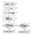
さらに他の実施例では、以下に述べるようにスペクトル解析を行う必要がなく、広い帯域幅のトランスデューサの必要はない。この特定の実施例では、広い帯域幅のトランスデューサを使用し、広い帯域幅のトランスデューサと共に使用する高周波数と低周波数チャンネルは、広い帯域幅(即ち、より短いパルス)で、相互に十分に分離しているが、ピーク出力より3dB低い中心周波数より上の周波数とピーク出力より低い中心周波数より下の周波数の範囲内で、トランスデューサの既知で十分高い感度を考慮に入れても良い。しかし、この実施例はまた、狭い帯域幅のトランスデューサを使用し、狭い帯域幅のトランスデューサと共に使用する高い周波数と低い周波数チャンネルは、より狭い帯域幅(即ち、より長いパルス)で、相互に十分に分離しているが、ピーク出力より3dB低い中心周波数より上の周波数とピーク出力より低い中心周波数より下の周波数の範囲外で、トランスデューサの既知で十分高い感度を考慮に入れても良い。図4は、この特定の実施例の簡単化したフローチャートであり、高周波数と低周波数を使用し、2つの連続した画像フレームを得て、これを使用して血液と組織を識別する。この特定の実施例では(簡単のため、狭い帯域幅のトランスデューサについて記述する)、トランスデューサは、2つの周波数(高と低)における2つの狭帯域トーンを送信でき、ここにトランスデューサは、2つの周波数トーンについて既知で十分高い感度を有する。
【0021】
ステップ111に示すように、トランスデューサは、f1で狭帯域低周波数トーンを送信し、第1画像フレームを得る。次に、トランスデューサは、f2で狭帯域低周波数トーンを送信し、第2画像フレームを得る(ステップ113)。前述したように、回転したトランスデューサからの複数の放射ベクトルは、画像フレームとなる。もちろん、他の実施例では、高周波数トーンと低周波数トーンにより連続する画像フレームが得られるなら、高周波数トーン即ちチャンネルを使用して第1画像フレームを得て、低周波数トーン即ちチャンネルを使用して第2画像フレームを得ることも出来る。ステップ115で、2つの連続する画像は減算される。ステップ117に示すように、組織部分は大部分相殺され、血液部分は相殺されない。2つのトーン周波数で反射したエコーの間の強度は、組織では同じで血液では異なるからである。例えば、減算した画像情報をマスクとして使用し、表示された画像の血液スペックルを除去することが出来る。もちろん、この実施例では、血液の空間分布を求めるためには、2つの画像フレームを得る時間がかかる。この実施例では、各エコーの帯域幅は、キロヘルツ(kHz)の範囲で、チャンネルは相互に出来るだけ離れるが、図1Bについて上述したように、両方のチャンネルがトランスデューサ既知の感度の範囲内である。この実施例の上述した記述も、既知の感度に関して図2の実施例について記述したのと同様に、高周波数と低周波数トーンにおけるトランスデューサの既知の感度を考慮に入れる。
【0022】
本発明はRFデジタル化を利用するので、より良いデジタル化が必要である(即ち、より多いサンプル数が必要)。こうすると、信号の包絡線を検出するだけでなく、個々の信号を検出し、分析を細かく行うことが出来る。10MHz等の低周波数のf0を有するトランスデューサが必要なある特定の用途では、直接サンプリングデジタル化を使用することが出来る。一方、40MHz等の高周波数のf0を有するトランスデューサが必要なある特定の用途では、高RFデジタル化のための公知の技術を使用することが出来る。
【0023】
本発明は、血液スペックル検出の唯一の手段として使用することが出来、または、血液スペックル検出の従来の強度ベースと移動ベースの解析の補助として使用し、管腔と脈間壁の境界を線引きするのに使用することができる。従って、本発明は、血液を検出する改善された性能を得られ、表示された画像の検出された血液に独自の色を割当てる、または表示された画像から検出された血液を完全に除去する用途に使用できる。本発明を特定の実施例を参照して説明してきた。本発明の精神と範囲から離れずに、前述したこと、及び形と詳細の他の変形は、当業者には明らかであろう。それゆえ、本発明は、請求の範囲に示される以外には、限定されることはない。
【図面の簡単な説明】
【図1A】 本発明の特定の実施例による血管内超音波像形成システムのブロック線図である。
【図1B】 本発明の特定の実施例によるトランスディユーサの出力感度を周波数の関数として示す簡単化した図である。
【図2】 スペクトル全体を解析して血液と組織を識別する特定の実施例の簡単化したフローチャートである。
【図3】 2つの別の周波数のみでスペクトル解析を行い血液と組織を識別する他の特定の実施例の簡単化したフローチャートである。
【図4】 高周波数と低周波数を使用し、2つの連続した画像フレームを得て、血液と組織を識別する別の特定の実施例の簡単化したフローチャートである。[0001]
(Background of the Invention)
The present invention relates to high-resolution intravascular image formation, and more particularly, to intravascular ultrasonic image formation and a technique for improving image quality.
[0002]
In intracavitary or intravascular ultrasound (also referred to as IVUS) imaging, imaging a vascular wall structure at high resolution requires imaging at a high ultrasound frequency. One type of intracavitary system uses a unidirectional ultrasonic exciter / detector within a catheter probe placed in a blood vessel to collect signal data from echoes of ultrasonic energy emitted from within the blood vessel. In particular, a vector is created by sending an ultrasonic pressure wave focused from a transducer within the catheter in a radial direction and collecting echoes from the target area with the same transducer. Multiple radiation vectors from the rotated transducer create an image frame. One processor performs image processing (eg, stabilization of moving images, temporary filtering of blood speckles, and other image enhancement techniques) on the collected data, and a modified and filtered vessel on a raster scan display monitor Provide a display of the inside image.
[0003]
It is preferable to image at higher ultrasonic frequencies, especially in certain applications, over a wide frequency range (eg 5 MHz to 50 MHz). However, in high-frequency intravascular ultrasound imaging, backscattering of such images from blood cells is a significant problem. This is because the scattering of ultrasonic waves from blood cells is proportional to the fourth power of the frequency, and the higher the frequency of ultrasonic waves, the more backscattering from blood. As a result, echoes from blood molecules are undesirable because the lumen-vessel wall contrast is reduced. This is because it is necessary to determine the blood / tissue boundary in order to confirm the degree of narrowing of the vessel and to determine the spatial spread of the plaque. Therefore, in order to improve the image display, it is necessary to detect an echo of an ultrasonic image due to backscattering from blood (an irregular pattern of backscattering from blood is called “blood speckle”). Once detected, blood speckle can be removed or suppressed to a level that can distinguish the wall structure from the blood, or can be distinguished by giving the blood a different display color, and / or blood / tissue boundaries. Can be used to draw better.
[0004]
Various techniques have been used to detect blood speckle in images in intravascular ultrasound imaging. These techniques are not always useful in distinguishing between blood and tissue. It is based on important assumptions that are not always true. Some techniques are based on the assumption that the intensity of energy scatter from blood is low compared to the intensity of scatter from tissue to distinguish between blood and tissue. Other techniques are based on the assumption that blood moves much faster compared to tissue and the Doppler signal is different from tissue. However, implementation may violate such assumptions. In particular, the energy scattered from the blood may be as bright as the scattering from the tissue, and / or the blood may move very slowly or not at all. While these techniques are generally effective, they are less effective in situations where these assumptions do not apply.
In view of the foregoing, there is an alternative or auxiliary method and apparatus that detects blood speckles and eliminates or clearly identifies blood-induced echoes from the display of intraluminal ultrasound images. is necessary.
[0005]
(Summary of Invention)
The present invention provides an improved method and apparatus for detecting blood speckle. The present invention takes advantage of the fact that the energy scattering intensity from blood shows a high frequency dependence, whereas the scattering intensity from tissue does not have a strong frequency dependence. In certain embodiments, the present invention provides for blood speckle in intravascular ultrasound imaging, particularly in situations where blood scatter intensity is close to tissue scatter intensity and / or blood moves slowly or not at all. Provides a particularly simple and useful solution for dealing with problems.
[0006]
According to a particular embodiment, the present invention provides a method for detecting blood speckles in an ultrasound blood vessel image within a blood vessel. The method includes irradiating a target in a blood vessel with ultrasonic RF energy, generating an ultrasonic echo from the target in the blood vessel, and converting the ultrasonic echo from the target in the blood vessel into a received RF signal. Prepare. The method also comprises performing spectral analysis of at least a portion of the received RF signal and providing spectral intensity information of the received RF signal. The intensity information includes a first luminance intensity at a high frequency in the spectrum and a second luminance intensity at a low frequency in the spectrum. This method further compares the first luminance intensity with the second luminance intensity. If the first luminance intensity and the second luminance intensity are substantially equal, the target in the blood vessel is determined to be tissue, and the first luminance intensity is the first luminance intensity. If it is greater than 2 luminance intensity, the target in the blood vessel is determined to be blood. This determining step takes into account high and low frequency intensity sensitivities. In some specific embodiments, spectral analysis is performed by full Fourier analysis or by filtering for high and low frequencies.
[0007]
In another particular embodiment, the present invention provides a method for detecting blood speckles in an ultrasound vessel image within a blood vessel. This method irradiates a target in a blood vessel with ultrasonic RF energy of a first frequency, generates an ultrasonic echo from the target in the blood vessel, forms a first image frame, and applies a second frequency to the target in the blood vessel. Irradiating with ultrasonic RF energy to generate an ultrasonic echo from the intravascular target to form a second image frame. The first and second image frames are continuous in time, one of the first and second frequencies being a low frequency and the other being a high frequency. The method also includes subtracting the first and second image frames to obtain a subtracted image, and the substantially cancelled portion of the subtracted image frame is tissue, and the non-cancelled portion of the subtracted image frame is blood. The step which asks for it is provided. This determining step takes into account high and low frequency intensity sensitivities.
[0008]
According to yet another specific embodiment, the present invention provides an apparatus for an ultrasonic angiography system. The apparatus comprises a transducer having a frequency bandwidth of known and sufficient intensity sensitivity at first and second frequencies. The transducer uses ultrasound waves transmitted at the first and second frequencies to obtain echoes from the target in the blood vessel and form an image in the blood vessel. The first and second frequencies areFrom peak power3dB lowerBelow the center frequencyFrequency andFrom peak power3dBAbove low center frequencyBetween frequencies. The apparatus also comprises a signal processing device and a computer readable medium. A signal processing device can be coupled to the transducer and display to display an intravascular image. A computer readable medium is coupled to be read by the signal processing device and stores a computer readable program, whereby the first intensity intensity of the echo from the first frequency ultrasound is determined by the second frequency. In comparison with the second luminance intensity of the echo from the ultrasonic wave, blood speckles in the intravascular image are detected.
[0009]
These and other embodiments of the present invention, its advantages and aspects are described below in conjunction with the detailed description and drawings.
[0010]
(Description of specific examples)
The present invention provides improved image processing for accurately identifying blood and tissue in an intravascular ultrasound imaging system. The present invention, according to certain embodiments, may use spectral analysis to distinguish blood from tissue. In particular, the present invention shows that the intensity of energy scattering from blood (ie, blood cells are particles about 2 μm thick, about 7 μm in diameter and much smaller than the wavelength of ultrasonic energy) is highly frequency dependent, Utilizes the fact that the scattering intensity from is not strongly frequency dependent. That is, for scattering by blood, the scattering intensity at higher frequencies is much stronger than the scattering intensity at lower frequencies. Since the spectrum provides information that there is frequency dependence, examining the spectrum provides information about the size of the reflector, indicating whether the reflector is blood or tissue.
[0011]
The present invention provides an image processing method for use in connection with the intravascular ultrasound imaging system shown in FIG. 1A. Referring to FIG. 1A, one type of block diagram of an intravascular
[0012]
The collected data is converted into pixels that represent the points of the scanned (swept or rotated) two-dimensional image and assigned, for example, a value on a gray scale between black and white. Of course, in other embodiments, colors can also be assigned. This image represents a cross-sectional “slice” of the structure of the
[0013]
According to a particular embodiment of the present invention, echo radio frequency (RF) is collected and then in the frequency domain using Fourier analysis to analyze the spectrum, as is well known in the industry. Analyzed. FIG. 2 is a simplified diagram illustrating a specific example of analyzing the entire spectrum. The electronics of the device for collecting RF echoes need to handle higher frequencies and have a higher dynamic range compared to devices used in a log-compressed envelope of the reflected echo. According to this particular embodiment, the transducer transmits RF over its full bandwidth (indicated by step 51) and receives an RF echo signal (step 55). Calculated using Fourier analysis (step 59), the output spectrum of the RF echo signal represents the nature of the reflector and gives information to better distinguish between blood and tissue. In this particular embodiment, after collecting RF and performing spectral analysis, the received RF signal intensities at two frequency widths (bins) are compared. In particular, the intensity of the spectrum in two frequency bins (higher frequency bin and lower frequency bin) where the transducer has a known sensitivity is examined. In particular, this embodiment requires the use of a transducer having a wide bandwidth including low frequency bins that are substantially well known and sufficiently high sensitivity and high frequency bins.
[0014]
FIG. 1B shows a transducer (transducer center frequency f as a function of frequency).0The peak output there is PPEAK) Is a simplified diagram of output sensitivity. High frequency bin and low frequency binFrom peak power3dB lowerBelow the center frequencyFrequency f-3dBLOW(Output is PPEAKHalf off0Lower frequency) andFrom peak power3dBAbove low center frequencyFrequency f-3dBHIGH(Output is PPEAKF which becomes half of0It is preferable to fall within the range between higher frequencies). In the preferred embodiment, both high and low frequency bins areFrom peak power3dB lowerBelow the center frequencyFrequency f-3dBLOWAnd f0Is selected to fall within the range between. However, in other embodiments, the high frequency bin and the low frequency bin are f0WhenFrom peak power3dBAbove low center frequencyFrequency f-3dBHIGHYou may choose to enter the range between. In another embodiment, for example, the low frequency bin is f0(Frequency f at which the transducer output peaks)0)WhenFrom peak power3dB lowerBelow the center frequencyFrequency f-3dBLOW(Output is PPEAKF which becomes half of0The higher frequency bin is selected to fall in the range between the lower frequency) and the center frequency f of the transducer0WhenFrom peak power3dBAbove low center frequencyFrequency f-3dBHIGH(Output is PPEAKF which becomes half of0It may be selected to fall within a range between higher frequencies). The two frequency bins should also be selected as far as possible from each other without departing from the frequency range of known and sufficiently sensitive transducers (the bandwidths of each frequency bin do not overlap and Do n’t be too close). For example, if a frequency bin is selected near the center frequency, a narrower frequency bin should be used. The frequency bin is selected further away from the center frequencyEvenThe bottle isFrom peak power3dBLowerfrequencyRange up toAs long as it remains within, a wider band of frequency bins can be used. By comparing the spectral intensities in these two frequency bins (taking into account the specific intensity sensitivity in each bin), it can be determined whether the echo is reflected from the tissue or from the blood.
[0015]
If the spectral intensities in these two frequency bins are approximately equal as shown in step 63 (considering the known intensity sensitivity in each frequency bin), the echo is reflected from the tissue and the particular pixel is the tissue (Step 65). If the intensity of the high frequency bin is greater than the intensity of the low frequency bin as shown in step 67 (considering the known intensity sensitivity in each frequency bin), the reflected echo will come from the blood and the specific pixel Is required to be blood (step 69). In this embodiment, the steps shown in FIG. 2 are performed on each radiation spoke, and the intensity of the high frequency and low frequency bins is compared for each sampling point of the radiation spoke to analyze the entire spectrum. In the exemplary implementation of this particular embodiment, the center frequency of the transducer is about 40 MHz, the bandwidth is about 20 MHz, and full Fourier analysis is included, so analysis and testing of the entire spectrum is computationally intensive. For certain applications, this particular embodiment may be preferred. This is because the obtained information (such as spectral analysis of the entire spectrum or the like) may be useful for other purposes in addition to detecting blood speckle.
[0016]
In other particular embodiments, the spectral analysis may be performed at two predetermined distinct frequencies for the transducer in the catheter. FIG. 3 is a simplified flowchart illustrating a specific embodiment for performing spectral analysis only at two separate frequencies. This embodiment also has a low frequency f, as described above with reference to FIG.1And high frequency f2It is necessary to use a transducer having a wide bandwidth including: The two frequencies have a known sensitivity for the particular transducer in the catheter and have a suitable frequency range (as described above,From peak power3dBAbove low center frequencyFrequency andFrom peak power3dB lowerBelow the center frequencySelected to enter (between frequencies). The following description also assumes that the intensity comparison at two separate frequencies takes into account the known sensitivity of the transducer at the individual frequencies, as described for the embodiment of FIG.
[0017]
According to this particular embodiment, the transducer transmits RF along its entire bandwidth (indicated by step 91) and receives an RF echo signal (step 95). In this embodiment, spectrum analysis is performed without performing Fourier analysis of the RF signal, and the entire spectrum is obtained. Instead, two separate frequencies, the low frequency f1And high frequency f2Thus, spectrum analysis is performed by bandpass filtering (step 97). In one particular embodiment, bandpass filtering is performed on individual sets of counts obtained by a look-up table (LUT). Here, the LUT is incorporated (eg,
[0018]
By comparing the intensities at these two separate frequencies (step 99), it is determined in this embodiment whether echo is reflected from tissue or blood, similar to the embodiment shown in FIG. That is, if the spectral intensities at these two frequencies are approximately equal (step 101), the echo is reflected from the tissue and the particular pixel is determined to be tissue (step 103). If the high frequency f2Frequency f with low intensity1If the intensity is greater than (step 105), the reflected echo comes from the blood and the particular pixel is determined to be blood (step 107). In this embodiment, the received RF signal is subjected to spectrum analysis and intensity-based comparison at two frequencies. That is, the steps shown in FIG. 3 are performed for each radiation spoke, and the intensity comparison is performed at a high frequency and a low frequency for each sampling point of the radiation spoke. In the illustrated implementation, the center frequency of the transducer is about 40 MHz, for a total bandwidth of about 20 MHz, and the device processing and memory requirements are low. This embodiment is less computationally intensive by avoiding a complete Fourier analysis of the entire spectrum of the RF signal.
[0019]
The implementation of the embodiments described for these two specific embodiments may use a wideband transducer with a center frequency of about 40 MHz and a bandwidth of about 20 MHz, while other implementations may use other types of transducers. Can also be used. As an example, a wideband transducer with a center / bandwidth range of: About 9 MHz, about 3.6-5.4 MHz bandwidth; about 12 MHz, about 4.8-7.2 MHz bandwidth; about 30 MHz, about 12-18 MHz bandwidth. Transducers with other bandwidths, such as about 100 MHz, about 40-50 MHz bandwidth can also be used. However, the wavelength corresponding to the high frequency or frequency bin used in the two specific embodiments above needs to be larger than the typical diameter of a blood cell (about 7 μm). A transducer attached to the catheter used in the IVUS imaging system easily provides information to the image processor through the catheter ID. Such information includes the center frequency of a particular transducer, and additional information that can be provided is used in the present invention.From peak power3dBAbove low center frequencyFrequency andFrom peak power3dB lowerBelow the center frequencyThe frequency and / or the overall sensitivity intensity spectrum of a particular transducer may be included.
[0020]
In still other embodiments, there is no need for spectral analysis as described below, and no need for wide bandwidth transducers. In this particular embodiment, a wide bandwidth transducer is used and the high frequency and low frequency channels used with the wide bandwidth transducer are well separated from each other with a wide bandwidth (ie shorter pulses). ButFrom peak power3dBAbove low center frequencyFrequency andFrom peak powerLowBelow the center frequencyWithin the frequency range, the known and sufficiently high sensitivity of the transducer may be taken into account. However, this embodiment also uses a narrow bandwidth transducer, and the high and low frequency channels used with the narrow bandwidth transducer are sufficiently close to each other with a narrower bandwidth (ie, longer pulses). Separated,From peak power3dBAbove low center frequencyFrequency andFrom peak powerLowBelow the center frequencyOutside the frequency range, the known and sufficiently high sensitivity of the transducer may be taken into account. FIG. 4 is a simplified flowchart of this particular embodiment, using high and low frequencies to obtain two consecutive image frames that are used to identify blood and tissue. In this particular embodiment (for simplicity, a narrow bandwidth transducer is described), the transducer can transmit two narrowband tones at two frequencies (high and low), where the transducer has two frequencies Known tones and sufficiently sensitive.
[0021]
As shown in
[0022]
Since the present invention utilizes RF digitization, better digitization is required (ie, a higher number of samples is required). In this way, not only the envelope of the signal but also individual signals can be detected and analyzed in detail. F of low frequency such as 10MHz0In certain applications where a transducer with a direct sampling is required, direct sampling digitization can be used. On the other hand, f of high frequency such as 40 MHz0In certain applications where a transducer having a high frequency is required, known techniques for high RF digitization can be used.
[0023]
The present invention can be used as the only means of blood speckle detection, or as an aid to conventional intensity-based and movement-based analysis of blood speckle detection, and to define the boundary between the lumen and the interpulse wall. Can be used to draw. Accordingly, the present invention provides improved performance for detecting blood and assigns a unique color to the detected blood in the displayed image or completely removes the detected blood from the displayed image Can be used for The invention has been described with reference to specific embodiments. The foregoing and other variations in form and detail will be apparent to those skilled in the art without departing from the spirit and scope of the invention. Therefore, the invention is not limited except as indicated in the claims.
[Brief description of the drawings]
FIG. 1A is a block diagram of an intravascular ultrasound imaging system according to a specific embodiment of the present invention.
FIG. 1B is a simplified diagram illustrating the output sensitivity of a transducer according to a particular embodiment of the invention as a function of frequency.
FIG. 2 is a simplified flowchart of a particular embodiment that analyzes the entire spectrum to identify blood and tissue.
FIG. 3 is a simplified flowchart of another particular embodiment for spectral analysis at only two different frequencies to identify blood and tissue.
FIG. 4 is a simplified flowchart of another particular embodiment that uses two high and low frequencies to obtain two consecutive image frames to identify blood and tissue.
Claims (16)
Translated fromJapaneseトランスデューサが、血管内のターゲットに照射するための超音波RFエネルギーを発生して、超音波エコーを受信するステップと、
プロセッサが、血管内のターゲットからの前記超音波エコーを受信したRF信号に変換するステップと、
前記プロセッサが、前記受信したRF信号の少なくとも一部のスペクトル解析を行い、前記受信したRF信号のスペクトルの強度情報を提供するステップと、を備え、前記強度情報には、前記スペクトル内の高周波数の第1周波数の第1輝度強度と、前記スペクトル内の低周波数の第2周波数の第2輝度強度とが含まれ、前記トランスデューサは前記第1、第2周波数の両方で既知の信号検出感度を有し、
前記プロセッサが、前記トランスデューサの前記第1、第2周波数の信号検出感度の差を考慮して、前記第1輝度強度と前記第2輝度強度とを比較し、前記第1、第2周波数を使用したエコー信号強度の周波数依存性を求めることに基づいて、受取った超音波エコーが血液スペックルから反射されたか患者の組織から反射されたかを求めるステップと、
前記プロセッサが、前記第1輝度強度と前記第2輝度強度が等しければ、前記血管内のターゲットは組織であると求め、前記第1輝度強度が前記第2輝度強度より大きければ、前記血管内のターゲットは血液であると求めるステップと、
を備えることを特徴とする方法。In the operation method of the intravascular ultrasonic blood vessel imaging device,
A transducer generating ultrasonic RF energy to illuminate a target in the blood vessel and receiving an ultrasonic echo;
A processor converts the ultrasonic echo from a target in the blood vessel into a received RF signal;
The processor performing spectral analysis of at least a portion of the received RF signal and providing spectrum intensity information of the received RF signal, wherein the intensity information includes a high frequency in the spectrum. A first luminance intensity at afirst frequency ofthe first frequency and a second luminance intensity at asecond lower frequency in the spectrum, thetransducer having a known signal detection sensitivity at both the first and second frequencies. Have
The processor compares the first luminance intensity with the second luminance intensityin consideration of a difference in signal detection sensitivity between the first and second frequencies of the transducer,and uses the first and second frequencies. a stepof echo signal intensity based on determining the frequency dependence of Rudetermined whether ultrasonic echoes received are reflected from one patient's tissue is reflected from the blood speckle,
The processor determinesthat the targetin the blood vessel is tissue if the first luminance intensity is equal to the second luminance intensity, and if the first luminance intensity is greater than the second luminance intensity, Asking the target to be blood,
A method comprising the steps of:
前記プロセッサが、前記血管内のターゲットに選択した第1陰影を割り当て、前記第1輝度強度が前記第2輝度強度より大きいと求められれば、選択した第2陰影を割り当て、
前記プロセッサが、前記血管内の超音波血管画像に、ディスプレー上で、組織部分に前記選択した第1陰影を付け、血液部分に前記選択した第2陰影を付けて提供する、
ステップをさらに備える請求項1に記載の方法。If it is determined that the first luminance intensity is equal to the second luminance intensity,
The processor assigns a selected first shadow to a target in the blood vessel, and if the first luminance intensity is determined to be greater than the second luminance intensity, assigns the selected second shadow;
The processor provides an ultrasonic blood vessel image in the blood vessel on the display with the first selected shadow on a tissue portion and the second selected shadow on a blood portion.
The method of claim 1, further comprising a step.
第1周波数と第2周波数における高い強度感度を含む周波数帯域幅を有するトランスデューサであって、前記トランスデューサの中心周波数における出力の半分の出力となる前記中心周波数より下の周波数と、前記中心周波数における出力の半分の出力となる前記中心周波数より上の周波数の間の前記第1周波数と第2周波数で送信された超音波を使用して、血管内のターゲットからエコーを得て、血管内画像を形成する該トランスデューサ、を備え、前記トランスデューサは前記第1、第2周波数の両方で既知の信号検出感度を有し、前記第1周波数は前記第2周波数より大きく、
前記トランスデューサと、前記血管内画像を表示するディスプレーとに結合することが出来るプロセッサを備える信号処理デバイス、を備え、
前記プロセッサは、前記コンピュータで読取り可能なプログラムを記憶するためコンピュータで読取り可能な媒体を使用し、前記コンピュータで読取り可能なプログラムは、前記トランスデューサの前記第1、第2周波数の信号検出感度の差を考慮して、前記第1周波数における超音波からのエコーの第1輝度強度を、前記第2周波数における超音波からのエコーの第2輝度強度と比較し、前記第1、第2周波数を使用したエコー信号強度の周波数依存性を求めることに基づいて、受取った超音波エコーが血液スペックルから反射されたか患者の組織から反射されたかを求め、
前記信号処理デバイスは、前記第1輝度強度が前記第2輝度強度より大きいとき、前記血管内画像の前記血管内のターゲットは血液スペックルであると求めるように構成されている装置。In the intravascular ultrasound blood vessel imaging device,
A transducer having a frequency bandwidth including high intensity sensitivity at a first frequency and a second frequency, the frequency below the center frequency being an output half the output at the center frequency of the transducer, and the output at the center frequency Using the ultrasonic waves transmitted at the first frequency and the second frequency between the frequencies above the center frequency, which is half the output, obtain an echo from the target in the blood vessel and form an intravascular image The transducerhaving a known signal detection sensitivity at both the first and second frequencies, the first frequency being greater than the second frequency,
A signal processing device comprising a processor that can be coupled to the transducer and a display for displaying the intravascular image;
The processor uses a computer readable medium to store the computer readable program, the program being readable bythe difference in signal detection sensitivity of the transducer at the first and second frequencies. taking into account, the first luminance intensity of the echo from the ultrasonic wave in the first frequency, compared with the second luminance intensity of the echo from the ultrasonic wave in the second frequency,using said first, second frequency Determining whether the received ultrasound echo is reflected from the blood speckle or from the patient's tissue based on determining the frequency dependence of the echo signal intensity
The signal processing device isconfigured to determinethat the intravascular target of the intravascular image is blood speckle when the first luminance intensity is greater than the second luminance intensity.
Applications Claiming Priority (3)
| Application Number | Priority Date | Filing Date | Title |
|---|---|---|---|
| US08/936,043 | 1997-09-23 | ||
| US08/936,043US5876343A (en) | 1997-09-23 | 1997-09-23 | Methods and apparatus for blood speckle detection in an intravascular ultrasound imaging system |
| PCT/IB1998/001664WO1999015874A2 (en) | 1997-09-23 | 1998-09-22 | Methods and apparatus for blood speckle detection in an intravascular ultrasound imaging system |
Publications (3)
| Publication Number | Publication Date |
|---|---|
| JP2003510102A JP2003510102A (en) | 2003-03-18 |
| JP2003510102A5 JP2003510102A5 (en) | 2006-01-05 |
| JP4394828B2true JP4394828B2 (en) | 2010-01-06 |
Family
ID=25468095
Family Applications (1)
| Application Number | Title | Priority Date | Filing Date |
|---|---|---|---|
| JP2000513125AExpired - LifetimeJP4394828B2 (en) | 1997-09-23 | 1998-09-22 | Ultrasound blood vessel image forming apparatus and operating method thereof |
Country Status (7)
| Country | Link |
|---|---|
| US (3) | US5876343A (en) |
| EP (1) | EP1032309B1 (en) |
| JP (1) | JP4394828B2 (en) |
| CA (1) | CA2305653C (en) |
| DE (1) | DE69832412T2 (en) |
| ES (1) | ES2248918T3 (en) |
| WO (1) | WO1999015874A2 (en) |
Families Citing this family (92)
| Publication number | Priority date | Publication date | Assignee | Title |
|---|---|---|---|---|
| DE19681455T1 (en)* | 1995-06-15 | 1998-07-02 | Regent Of The University Of Mi | Method and device for a composition and a representation of a three-dimensional image of two-dimensional ultrasound (scanning data) |
| US5876343A (en)* | 1997-09-23 | 1999-03-02 | Scimed Life Systems, Inc. | Methods and apparatus for blood speckle detection in an intravascular ultrasound imaging system |
| US6181810B1 (en)* | 1998-07-30 | 2001-01-30 | Scimed Life Systems, Inc. | Method and apparatus for spatial and temporal filtering of intravascular ultrasonic image data |
| JP2000126182A (en)* | 1998-10-27 | 2000-05-09 | Mitani Sangyo Co Ltd | Tumor diagnosis method |
| US20010031924A1 (en)* | 2000-03-02 | 2001-10-18 | Seward James B. | Small ultrasound transducers |
| US7037270B2 (en)* | 2000-03-02 | 2006-05-02 | Mayo Foundation For Medical Education And Research | Small ultrasound transducers |
| US6554774B1 (en)* | 2000-03-23 | 2003-04-29 | Tensys Medical, Inc. | Method and apparatus for assessing hemodynamic properties within the circulatory system of a living subject |
| US6454715B2 (en)* | 2000-04-11 | 2002-09-24 | Scimed Life Systems, Inc. | Methods and apparatus for blood speckle detection in an intravascular ultrasound imaging system |
| US6416492B1 (en) | 2000-09-28 | 2002-07-09 | Scimed Life Systems, Inc. | Radiation delivery system utilizing intravascular ultrasound |
| US6626836B2 (en)* | 2001-04-04 | 2003-09-30 | Siemens Medical Solutions Usa, Inc. | Adaptive signal processing scheme for contrast agent imaging |
| US7846096B2 (en)* | 2001-05-29 | 2010-12-07 | Ethicon Endo-Surgery, Inc. | Method for monitoring of medical treatment using pulse-echo ultrasound |
| US6592520B1 (en)* | 2001-07-31 | 2003-07-15 | Koninklijke Philips Electronics N.V. | Intravascular ultrasound imaging apparatus and method |
| NL1019612C2 (en)* | 2001-12-19 | 2003-06-20 | Gemeente Amsterdam | Steam superheater. |
| US7927275B2 (en) | 2002-08-26 | 2011-04-19 | The Cleveland Clinic Foundation | System and method of aquiring blood-vessel data |
| US7359554B2 (en)* | 2002-08-26 | 2008-04-15 | Cleveland Clinic Foundation | System and method for identifying a vascular border |
| TR201902962T4 (en)* | 2002-08-26 | 2019-03-21 | Cleveland Clinic Found | System and method for characterizing vascular tissue. |
| US7074188B2 (en) | 2002-08-26 | 2006-07-11 | The Cleveland Clinic Foundation | System and method of characterizing vascular tissue |
| US7998073B2 (en) | 2003-08-04 | 2011-08-16 | Imacor Inc. | Ultrasound imaging with reduced noise |
| DE10350224B4 (en)* | 2003-10-27 | 2007-07-26 | Sartorius Ag | Method for determining moisture and density of a dielectric material |
| US8641627B2 (en)* | 2003-11-26 | 2014-02-04 | Imacor Inc. | Transesophageal ultrasound using a narrow probe |
| US7874990B2 (en)* | 2004-01-14 | 2011-01-25 | The Cleveland Clinic Foundation | System and method for determining a transfer function |
| US20080051660A1 (en)* | 2004-01-16 | 2008-02-28 | The University Of Houston System | Methods and apparatuses for medical imaging |
| US7215802B2 (en)* | 2004-03-04 | 2007-05-08 | The Cleveland Clinic Foundation | System and method for vascular border detection |
| US20050240105A1 (en)* | 2004-04-14 | 2005-10-27 | Mast T D | Method for reducing electronic artifacts in ultrasound imaging |
| US7946994B2 (en) | 2004-10-07 | 2011-05-24 | Tensys Medical, Inc. | Compact apparatus and methods for non-invasively measuring hemodynamic parameters |
| US7749249B2 (en) | 2006-02-21 | 2010-07-06 | Kardium Inc. | Method and device for closing holes in tissue |
| JP5441689B2 (en) | 2006-05-13 | 2014-03-12 | テンシス メディカル インコーポレイテッド | Continuous positioning apparatus and method |
| US20070270688A1 (en) | 2006-05-19 | 2007-11-22 | Daniel Gelbart | Automatic atherectomy system |
| US8449605B2 (en) | 2006-06-28 | 2013-05-28 | Kardium Inc. | Method for anchoring a mitral valve |
| US10028783B2 (en) | 2006-06-28 | 2018-07-24 | Kardium Inc. | Apparatus and method for intra-cardiac mapping and ablation |
| US9119633B2 (en) | 2006-06-28 | 2015-09-01 | Kardium Inc. | Apparatus and method for intra-cardiac mapping and ablation |
| US11389232B2 (en) | 2006-06-28 | 2022-07-19 | Kardium Inc. | Apparatus and method for intra-cardiac mapping and ablation |
| US8920411B2 (en) | 2006-06-28 | 2014-12-30 | Kardium Inc. | Apparatus and method for intra-cardiac mapping and ablation |
| US20100138191A1 (en)* | 2006-07-20 | 2010-06-03 | James Hamilton | Method and system for acquiring and transforming ultrasound data |
| US20080021319A1 (en)* | 2006-07-20 | 2008-01-24 | James Hamilton | Method of modifying data acquisition parameters of an ultrasound device |
| US20080021945A1 (en)* | 2006-07-20 | 2008-01-24 | James Hamilton | Method of processing spatial-temporal data processing |
| US7837610B2 (en) | 2006-08-02 | 2010-11-23 | Kardium Inc. | System for improving diastolic dysfunction |
| US11197651B2 (en) | 2007-03-08 | 2021-12-14 | Sync-Rx, Ltd. | Identification and presentation of device-to-vessel relative motion |
| US9305334B2 (en) | 2007-03-08 | 2016-04-05 | Sync-Rx, Ltd. | Luminal background cleaning |
| US9375164B2 (en) | 2007-03-08 | 2016-06-28 | Sync-Rx, Ltd. | Co-use of endoluminal data and extraluminal imaging |
| US11064964B2 (en) | 2007-03-08 | 2021-07-20 | Sync-Rx, Ltd | Determining a characteristic of a lumen by measuring velocity of a contrast agent |
| US10716528B2 (en) | 2007-03-08 | 2020-07-21 | Sync-Rx, Ltd. | Automatic display of previously-acquired endoluminal images |
| WO2008107905A2 (en) | 2007-03-08 | 2008-09-12 | Sync-Rx, Ltd. | Imaging and tools for use with moving organs |
| US8781193B2 (en) | 2007-03-08 | 2014-07-15 | Sync-Rx, Ltd. | Automatic quantitative vessel analysis |
| US9968256B2 (en) | 2007-03-08 | 2018-05-15 | Sync-Rx Ltd. | Automatic identification of a tool |
| US9629571B2 (en) | 2007-03-08 | 2017-04-25 | Sync-Rx, Ltd. | Co-use of endoluminal data and extraluminal imaging |
| US9275471B2 (en) | 2007-07-20 | 2016-03-01 | Ultrasound Medical Devices, Inc. | Method for ultrasound motion tracking via synthetic speckle patterns |
| US20100185085A1 (en)* | 2009-01-19 | 2010-07-22 | James Hamilton | Dynamic ultrasound processing using object motion calculation |
| CN101896117B (en) | 2007-10-12 | 2015-03-04 | 坦西斯医药股份有限公司 | Device and method for non-invasive measurement of arterial blood pressure in a patient |
| US8906011B2 (en) | 2007-11-16 | 2014-12-09 | Kardium Inc. | Medical device for use in bodily lumens, for example an atrium |
| US8489172B2 (en)* | 2008-01-25 | 2013-07-16 | Kardium Inc. | Liposuction system |
| US8206308B2 (en) | 2008-05-05 | 2012-06-26 | Boston Scientific Scimed, Inc. | Shielding for intravascular ultrasound imaging systems and methods of making and using |
| US20090287304A1 (en)* | 2008-05-13 | 2009-11-19 | Kardium Inc. | Medical Device for Constricting Tissue or a Bodily Orifice, for example a mitral valve |
| US8197413B2 (en)* | 2008-06-06 | 2012-06-12 | Boston Scientific Scimed, Inc. | Transducers, devices and systems containing the transducers, and methods of manufacture |
| EP2303385B1 (en) | 2008-06-19 | 2013-12-11 | Sync-RX, Ltd. | Stepwise advancement of a medical tool |
| WO2010039555A1 (en)* | 2008-09-23 | 2010-04-08 | Ultrasound Medical Devices, Inc. | System and method for flexible rate processing of ultrasound data |
| US10362962B2 (en) | 2008-11-18 | 2019-07-30 | Synx-Rx, Ltd. | Accounting for skipped imaging locations during movement of an endoluminal imaging probe |
| US9974509B2 (en) | 2008-11-18 | 2018-05-22 | Sync-Rx Ltd. | Image super enhancement |
| US9144394B2 (en) | 2008-11-18 | 2015-09-29 | Sync-Rx, Ltd. | Apparatus and methods for determining a plurality of local calibration factors for an image |
| US8855744B2 (en) | 2008-11-18 | 2014-10-07 | Sync-Rx, Ltd. | Displaying a device within an endoluminal image stack |
| US9095313B2 (en) | 2008-11-18 | 2015-08-04 | Sync-Rx, Ltd. | Accounting for non-uniform longitudinal motion during movement of an endoluminal imaging probe |
| US11064903B2 (en) | 2008-11-18 | 2021-07-20 | Sync-Rx, Ltd | Apparatus and methods for mapping a sequence of images to a roadmap image |
| US9101286B2 (en) | 2008-11-18 | 2015-08-11 | Sync-Rx, Ltd. | Apparatus and methods for determining a dimension of a portion of a stack of endoluminal data points |
| WO2010105197A2 (en)* | 2009-03-12 | 2010-09-16 | The General Hospital Corporation | Non-contact optical system, computer-accessible medium and method for measuring at least one mechanical property of tissue using coherent speckle techniques(s) |
| WO2011041571A2 (en) | 2009-10-01 | 2011-04-07 | Kardium Inc. | Medical device, kit and method for constricting tissue or a bodily orifice, for example, a mitral valve |
| CN102665569B (en) | 2009-10-12 | 2015-05-13 | 硅谷医疗器械有限公司 | Intravascular ultrasound system for co-registered imaging |
| US20120065506A1 (en) | 2010-09-10 | 2012-03-15 | Scott Smith | Mechanical, Electromechanical, and/or Elastographic Assessment for Renal Nerve Ablation |
| US8940002B2 (en) | 2010-09-30 | 2015-01-27 | Kardium Inc. | Tissue anchor system |
| US11259867B2 (en) | 2011-01-21 | 2022-03-01 | Kardium Inc. | High-density electrode-based medical device system |
| US9452016B2 (en) | 2011-01-21 | 2016-09-27 | Kardium Inc. | Catheter system |
| CA2764494A1 (en) | 2011-01-21 | 2012-07-21 | Kardium Inc. | Enhanced medical device for use in bodily cavities, for example an atrium |
| US9480525B2 (en) | 2011-01-21 | 2016-11-01 | Kardium, Inc. | High-density electrode-based medical device system |
| US9072511B2 (en) | 2011-03-25 | 2015-07-07 | Kardium Inc. | Medical kit for constricting tissue or a bodily orifice, for example, a mitral valve |
| US10292676B2 (en) | 2011-12-21 | 2019-05-21 | Volcano Corporaton | Method for visualizing blood and blood-likelihood in vascualar images |
| USD777926S1 (en) | 2012-01-20 | 2017-01-31 | Kardium Inc. | Intra-cardiac procedure device |
| USD777925S1 (en) | 2012-01-20 | 2017-01-31 | Kardium Inc. | Intra-cardiac procedure device |
| US10827977B2 (en) | 2012-05-21 | 2020-11-10 | Kardium Inc. | Systems and methods for activating transducers |
| US9198592B2 (en) | 2012-05-21 | 2015-12-01 | Kardium Inc. | Systems and methods for activating transducers |
| US9017321B2 (en) | 2012-05-21 | 2015-04-28 | Kardium, Inc. | Systems and methods for activating transducers |
| EP2863802B1 (en) | 2012-06-26 | 2020-11-04 | Sync-RX, Ltd. | Flow-related image processing in luminal organs |
| US10245007B2 (en) | 2013-03-15 | 2019-04-02 | Infraredx, Inc. | High resolution intravascular ultrasound imaging systems and methods |
| US9693754B2 (en) | 2013-05-15 | 2017-07-04 | Acist Medical Systems, Inc. | Imaging processing systems and methods |
| JP6353038B2 (en) | 2013-10-07 | 2018-07-04 | アシスト・メディカル・システムズ,インコーポレイテッド | Signal processing for intravascular imaging |
| JP6006769B2 (en)* | 2014-10-16 | 2016-10-12 | 株式会社日立製作所 | Ultrasonic diagnostic equipment |
| US10368936B2 (en) | 2014-11-17 | 2019-08-06 | Kardium Inc. | Systems and methods for selecting, activating, or selecting and activating transducers |
| US10722184B2 (en) | 2014-11-17 | 2020-07-28 | Kardium Inc. | Systems and methods for selecting, activating, or selecting and activating transducers |
| US10909661B2 (en) | 2015-10-08 | 2021-02-02 | Acist Medical Systems, Inc. | Systems and methods to reduce near-field artifacts |
| US10653393B2 (en) | 2015-10-08 | 2020-05-19 | Acist Medical Systems, Inc. | Intravascular ultrasound imaging with frequency selective imaging methods and systems |
| US11369337B2 (en) | 2015-12-11 | 2022-06-28 | Acist Medical Systems, Inc. | Detection of disturbed blood flow |
| WO2017117389A1 (en) | 2015-12-31 | 2017-07-06 | Acist Medical Systems, Inc. | Semi-automated image segmentation system and method |
| US10489919B2 (en) | 2016-05-16 | 2019-11-26 | Acist Medical Systems, Inc. | Motion-based image segmentation systems and methods |
| US11024034B2 (en) | 2019-07-02 | 2021-06-01 | Acist Medical Systems, Inc. | Image segmentation confidence determination |
Family Cites Families (17)
| Publication number | Priority date | Publication date | Assignee | Title |
|---|---|---|---|---|
| US4575799A (en)* | 1983-03-23 | 1986-03-11 | Fujitsu Limited | Ultrasonic living body tissue characterization system |
| US4561019A (en)* | 1983-05-16 | 1985-12-24 | Riverside Research Institute | Frequency diversity for image enhancement |
| US5187687A (en)* | 1985-06-20 | 1993-02-16 | Kontron Instruments Holding N.V. | Production of images |
| US4803994A (en)* | 1987-08-12 | 1989-02-14 | General Electric Company | Backscatter data collection technique for ultrasound |
| US5353798A (en)* | 1991-03-13 | 1994-10-11 | Scimed Life Systems, Incorporated | Intravascular imaging apparatus and methods for use and manufacture |
| US5255683A (en)* | 1991-12-30 | 1993-10-26 | Sound Science Limited Partnership | Methods of and systems for examining tissue perfusion using ultrasonic contrast agents |
| US5224483A (en)* | 1992-05-19 | 1993-07-06 | Hewlett-Packard Company | Adaptive contrast enhancement for scanned ultrasonic image |
| US5363849A (en)* | 1994-01-26 | 1994-11-15 | Cardiovascular Imaging Systems, Inc. | Enhancing intravascular ultrasonic blood vessel image |
| US5363850A (en)* | 1994-01-26 | 1994-11-15 | Cardiovascular Imaging Systems, Inc. | Method for recognition and reduction of blood speckle in blood vessel imaging system |
| US5417215A (en)* | 1994-02-04 | 1995-05-23 | Long Island Jewish Medical Center | Method of tissue characterization by ultrasound |
| NO943269D0 (en)* | 1994-09-02 | 1994-09-02 | Vingmed Sound As | Method for analyzing and measuring ultrasound signals |
| US5526816A (en)* | 1994-09-22 | 1996-06-18 | Bracco Research S.A. | Ultrasonic spectral contrast imaging |
| US5594807A (en)* | 1994-12-22 | 1997-01-14 | Siemens Medical Systems, Inc. | System and method for adaptive filtering of images based on similarity between histograms |
| US5479926A (en)* | 1995-03-10 | 1996-01-02 | Acuson Corporation | Imaging system display processor |
| JP3542858B2 (en)* | 1995-09-29 | 2004-07-14 | 株式会社日立メディコ | Ultrasound diagnostic equipment |
| US5720291A (en)* | 1996-03-22 | 1998-02-24 | Advanced Technology Laboratories, Inc. | Three dimensional medical ultrasonic diagnostic image of tissue texture and vasculature |
| US5876343A (en)* | 1997-09-23 | 1999-03-02 | Scimed Life Systems, Inc. | Methods and apparatus for blood speckle detection in an intravascular ultrasound imaging system |
- 1997
- 1997-09-23USUS08/936,043patent/US5876343A/ennot_activeExpired - Lifetime
- 1998
- 1998-09-22WOPCT/IB1998/001664patent/WO1999015874A2/enactiveIP Right Grant
- 1998-09-22JPJP2000513125Apatent/JP4394828B2/ennot_activeExpired - Lifetime
- 1998-09-22DEDE69832412Tpatent/DE69832412T2/ennot_activeExpired - Lifetime
- 1998-09-22CACA002305653Apatent/CA2305653C/ennot_activeExpired - Fee Related
- 1998-09-22EPEP98946674Apatent/EP1032309B1/ennot_activeExpired - Lifetime
- 1998-09-22ESES98946674Tpatent/ES2248918T3/ennot_activeExpired - Lifetime
- 1998-10-27USUS09/179,490patent/US6050946A/ennot_activeExpired - Lifetime
- 2000
- 2000-04-11USUS09/547,355patent/US6254541B1/ennot_activeExpired - Lifetime
Also Published As
| Publication number | Publication date |
|---|---|
| JP2003510102A (en) | 2003-03-18 |
| ES2248918T3 (en) | 2006-03-16 |
| WO1999015874A2 (en) | 1999-04-01 |
| DE69832412T2 (en) | 2006-08-10 |
| CA2305653A1 (en) | 1999-04-01 |
| US6254541B1 (en) | 2001-07-03 |
| EP1032309B1 (en) | 2005-11-16 |
| DE69832412D1 (en) | 2005-12-22 |
| EP1032309A4 (en) | 2004-05-19 |
| US6050946A (en) | 2000-04-18 |
| CA2305653C (en) | 2008-02-12 |
| WO1999015874A3 (en) | 1999-05-20 |
| US5876343A (en) | 1999-03-02 |
| EP1032309A2 (en) | 2000-09-06 |
Similar Documents
| Publication | Publication Date | Title |
|---|---|---|
| JP4394828B2 (en) | Ultrasound blood vessel image forming apparatus and operating method thereof | |
| US6454715B2 (en) | Methods and apparatus for blood speckle detection in an intravascular ultrasound imaging system | |
| US6267727B1 (en) | Methods and apparatus for non-uniform rotation distortion detection in an intravascular ultrasound imaging system | |
| JP4463422B2 (en) | Adaptive cancellation of ringdown artifacts in IVUS imaging | |
| US5417215A (en) | Method of tissue characterization by ultrasound | |
| JP2519777B2 (en) | Ultrasonic device and method for performing ultrasonic measurement and ultrasonic inspection | |
| US20120184853A1 (en) | System and Method for Characterizing Tissue Based Upon Split Spectrum Analysis of Backscattered Ultrasound | |
| US6814703B2 (en) | Apparatus and method for ultrasonic diagnostic imaging using a contrast medium | |
| US7666142B2 (en) | Ultrasound doppler diagnostic apparatus and image data generating method | |
| JP3397748B2 (en) | Color image display method and apparatus in color Doppler image system | |
| JP2003061964A (en) | Ultrasound diagnostic equipment | |
| US6132377A (en) | Medical diagnostic ultrasonic imaging system and method using differential sub-band detection techniques | |
| EP1515158A2 (en) | Ultrasound imaging method combined with the presence of contrast media in the body under examination | |
| JP2005193017A (en) | Method and system for classifying diseased part of mamma | |
| US5394874A (en) | Angiography using ultrasound | |
| JPH0467149B2 (en) | ||
| US6984211B2 (en) | Detection of tumor halos in ultrasound images | |
| JPH03188841A (en) | Ultrasound diagnostic equipment | |
| JP2002534185A (en) | Automatic spectral optimization method for Doppler ultrasound | |
| JPH0249102B2 (en) | ||
| JP3029315B2 (en) | Ultrasound blood flow imaging device | |
| GB2319841A (en) | Ultrasound scanning of tissue | |
| JPH0810257A (en) | Ultrasonic diagnostic equipment | |
| JP2508000B2 (en) | Ultrasonic diagnostic equipment | |
| JP2005318921A (en) | Ultrasonic diagnostic equipment |
Legal Events
| Date | Code | Title | Description |
|---|---|---|---|
| A521 | Request for written amendment filed | Free format text:JAPANESE INTERMEDIATE CODE: A523 Effective date:20050620 | |
| A621 | Written request for application examination | Free format text:JAPANESE INTERMEDIATE CODE: A621 Effective date:20050620 | |
| A977 | Report on retrieval | Free format text:JAPANESE INTERMEDIATE CODE: A971007 Effective date:20080220 | |
| A131 | Notification of reasons for refusal | Free format text:JAPANESE INTERMEDIATE CODE: A131 Effective date:20080507 | |
| A601 | Written request for extension of time | Free format text:JAPANESE INTERMEDIATE CODE: A601 Effective date:20080807 | |
| A602 | Written permission of extension of time | Free format text:JAPANESE INTERMEDIATE CODE: A602 Effective date:20080814 | |
| A521 | Request for written amendment filed | Free format text:JAPANESE INTERMEDIATE CODE: A523 Effective date:20081107 | |
| A131 | Notification of reasons for refusal | Free format text:JAPANESE INTERMEDIATE CODE: A131 Effective date:20090518 | |
| A521 | Request for written amendment filed | Free format text:JAPANESE INTERMEDIATE CODE: A523 Effective date:20090814 | |
| TRDD | Decision of grant or rejection written | ||
| A01 | Written decision to grant a patent or to grant a registration (utility model) | Free format text:JAPANESE INTERMEDIATE CODE: A01 Effective date:20091001 | |
| A01 | Written decision to grant a patent or to grant a registration (utility model) | Free format text:JAPANESE INTERMEDIATE CODE: A01 | |
| A61 | First payment of annual fees (during grant procedure) | Free format text:JAPANESE INTERMEDIATE CODE: A61 Effective date:20091016 | |
| R150 | Certificate of patent or registration of utility model | Free format text:JAPANESE INTERMEDIATE CODE: R150 | |
| FPAY | Renewal fee payment (event date is renewal date of database) | Free format text:PAYMENT UNTIL: 20121023 Year of fee payment:3 | |
| FPAY | Renewal fee payment (event date is renewal date of database) | Free format text:PAYMENT UNTIL: 20131023 Year of fee payment:4 | |
| R250 | Receipt of annual fees | Free format text:JAPANESE INTERMEDIATE CODE: R250 | |
| R250 | Receipt of annual fees | Free format text:JAPANESE INTERMEDIATE CODE: R250 | |
| R250 | Receipt of annual fees | Free format text:JAPANESE INTERMEDIATE CODE: R250 | |
| R250 | Receipt of annual fees | Free format text:JAPANESE INTERMEDIATE CODE: R250 | |
| R250 | Receipt of annual fees | Free format text:JAPANESE INTERMEDIATE CODE: R250 | |
| EXPY | Cancellation because of completion of term |