JP4394566B2 - Automatic injection device with a function to latch the active agent container - Google Patents
Automatic injection device with a function to latch the active agent containerDownload PDFInfo
- Publication number
- JP4394566B2 JP4394566B2JP2004367120AJP2004367120AJP4394566B2JP 4394566 B2JP4394566 B2JP 4394566B2JP 2004367120 AJP2004367120 AJP 2004367120AJP 2004367120 AJP2004367120 AJP 2004367120AJP 4394566 B2JP4394566 B2JP 4394566B2
- Authority
- JP
- Japan
- Prior art keywords
- injection device
- automatic injection
- latching
- needle protection
- protection tube
- Prior art date
- Legal status (The legal status is an assumption and is not a legal conclusion. Google has not performed a legal analysis and makes no representation as to the accuracy of the status listed.)
- Expired - Fee Related
Links
- 238000002347injectionMethods0.000titleclaimsdescription108
- 239000007924injectionSubstances0.000titleclaimsdescription108
- 239000013543active substanceSubstances0.000titleclaimsdescription16
- 239000012190activatorSubstances0.000claimsdescription32
- 238000007789sealingMethods0.000claims1
- 210000002105tongueAnatomy0.000description44
- 238000010586diagramMethods0.000description3
- 230000004913activationEffects0.000description2
- POIUWJQBRNEFGX-XAMSXPGMSA-NcathelicidinChemical compoundC([C@@H](C(=O)N[C@@H](CCCNC(N)=N)C(=O)N[C@@H](CCCCN)C(=O)N[C@@H](CO)C(=O)N[C@@H](CCCCN)C(=O)N[C@@H](CCC(O)=O)C(=O)N[C@@H](CCCCN)C(=O)N[C@@H]([C@@H](C)CC)C(=O)NCC(=O)N[C@@H](CCCCN)C(=O)N[C@@H](CCC(O)=O)C(=O)N[C@@H](CC=1C=CC=CC=1)C(=O)N[C@@H](CCCCN)C(=O)N[C@@H](CCCNC(N)=N)C(=O)N[C@@H]([C@@H](C)CC)C(=O)N[C@@H](C(C)C)C(=O)N[C@@H](CCC(N)=O)C(=O)N[C@@H](CCCNC(N)=N)C(=O)N[C@@H]([C@@H](C)CC)C(=O)N[C@@H](CCCCN)C(=O)N[C@@H](CC(O)=O)C(=O)N[C@@H](CC=1C=CC=CC=1)C(=O)N[C@@H](CC(C)C)C(=O)N[C@@H](CCCNC(N)=N)C(=O)N[C@@H](CC(N)=O)C(=O)N[C@@H](CC(C)C)C(=O)N[C@@H](C(C)C)C(=O)N1[C@@H](CCC1)C(=O)N[C@@H](CCCNC(N)=N)C(=O)N[C@@H]([C@@H](C)O)C(=O)N[C@@H](CCC(O)=O)C(=O)N[C@@H](CO)C(O)=O)NC(=O)[C@H](CC=1C=CC=CC=1)NC(=O)[C@H](CC(O)=O)NC(=O)CNC(=O)[C@H](CC(C)C)NC(=O)[C@@H](N)CC(C)C)C1=CC=CC=C1POIUWJQBRNEFGX-XAMSXPGMSA-N0.000description2
- 230000000694effectsEffects0.000description2
- 239000000243solutionSubstances0.000description2
- 239000000853adhesiveSubstances0.000description1
- 230000001070adhesive effectEffects0.000description1
- 238000011109contaminationMethods0.000description1
- 238000006073displacement reactionMethods0.000description1
- 230000009977dual effectEffects0.000description1
- 230000004927fusionEffects0.000description1
- 230000036512infertilityEffects0.000description1
- 238000001746injection mouldingMethods0.000description1
- 230000035515penetrationEffects0.000description1
- 238000002360preparation methodMethods0.000description1
- 230000000284resting effectEffects0.000description1
- 230000003068static effectEffects0.000description1
Images


Classifications
- A—HUMAN NECESSITIES
- A61—MEDICAL OR VETERINARY SCIENCE; HYGIENE
- A61M—DEVICES FOR INTRODUCING MEDIA INTO, OR ONTO, THE BODY; DEVICES FOR TRANSDUCING BODY MEDIA OR FOR TAKING MEDIA FROM THE BODY; DEVICES FOR PRODUCING OR ENDING SLEEP OR STUPOR
- A61M5/00—Devices for bringing media into the body in a subcutaneous, intra-vascular or intramuscular way; Accessories therefor, e.g. filling or cleaning devices, arm-rests
- A61M5/178—Syringes
- A61M5/31—Details
- A61M5/32—Needles; Details of needles pertaining to their connection with syringe or hub; Accessories for bringing the needle into, or holding the needle on, the body; Devices for protection of needles
- A61M5/3202—Devices for protection of the needle before use, e.g. caps
- A—HUMAN NECESSITIES
- A61—MEDICAL OR VETERINARY SCIENCE; HYGIENE
- A61M—DEVICES FOR INTRODUCING MEDIA INTO, OR ONTO, THE BODY; DEVICES FOR TRANSDUCING BODY MEDIA OR FOR TAKING MEDIA FROM THE BODY; DEVICES FOR PRODUCING OR ENDING SLEEP OR STUPOR
- A61M5/00—Devices for bringing media into the body in a subcutaneous, intra-vascular or intramuscular way; Accessories therefor, e.g. filling or cleaning devices, arm-rests
- A61M5/178—Syringes
- A61M5/20—Automatic syringes, e.g. with automatically actuated piston rod, with automatic needle injection, filling automatically
- A61M5/2033—Spring-loaded one-shot injectors with or without automatic needle insertion
- A—HUMAN NECESSITIES
- A61—MEDICAL OR VETERINARY SCIENCE; HYGIENE
- A61M—DEVICES FOR INTRODUCING MEDIA INTO, OR ONTO, THE BODY; DEVICES FOR TRANSDUCING BODY MEDIA OR FOR TAKING MEDIA FROM THE BODY; DEVICES FOR PRODUCING OR ENDING SLEEP OR STUPOR
- A61M5/00—Devices for bringing media into the body in a subcutaneous, intra-vascular or intramuscular way; Accessories therefor, e.g. filling or cleaning devices, arm-rests
- A61M5/178—Syringes
- A61M5/31—Details
- A61M5/315—Pistons; Piston-rods; Guiding, blocking or restricting the movement of the rod or piston; Appliances on the rod for facilitating dosing ; Dosing mechanisms
- A61M5/31565—Administration mechanisms, i.e. constructional features, modes of administering a dose
- A61M5/31566—Means improving security or handling thereof
- A61M5/31571—Means preventing accidental administration
- A—HUMAN NECESSITIES
- A61—MEDICAL OR VETERINARY SCIENCE; HYGIENE
- A61M—DEVICES FOR INTRODUCING MEDIA INTO, OR ONTO, THE BODY; DEVICES FOR TRANSDUCING BODY MEDIA OR FOR TAKING MEDIA FROM THE BODY; DEVICES FOR PRODUCING OR ENDING SLEEP OR STUPOR
- A61M5/00—Devices for bringing media into the body in a subcutaneous, intra-vascular or intramuscular way; Accessories therefor, e.g. filling or cleaning devices, arm-rests
- A61M5/178—Syringes
- A61M5/31—Details
- A61M5/315—Pistons; Piston-rods; Guiding, blocking or restricting the movement of the rod or piston; Appliances on the rod for facilitating dosing ; Dosing mechanisms
- A61M5/31565—Administration mechanisms, i.e. constructional features, modes of administering a dose
- A61M5/31576—Constructional features or modes of drive mechanisms for piston rods
- A61M5/31578—Constructional features or modes of drive mechanisms for piston rods based on axial translation, i.e. components directly operatively associated and axially moved with plunger rod
- A61M5/3158—Constructional features or modes of drive mechanisms for piston rods based on axial translation, i.e. components directly operatively associated and axially moved with plunger rod performed by axially moving actuator operated by user, e.g. an injection button
- A—HUMAN NECESSITIES
- A61—MEDICAL OR VETERINARY SCIENCE; HYGIENE
- A61M—DEVICES FOR INTRODUCING MEDIA INTO, OR ONTO, THE BODY; DEVICES FOR TRANSDUCING BODY MEDIA OR FOR TAKING MEDIA FROM THE BODY; DEVICES FOR PRODUCING OR ENDING SLEEP OR STUPOR
- A61M5/00—Devices for bringing media into the body in a subcutaneous, intra-vascular or intramuscular way; Accessories therefor, e.g. filling or cleaning devices, arm-rests
- A61M5/178—Syringes
- A61M5/31—Details
- A61M5/32—Needles; Details of needles pertaining to their connection with syringe or hub; Accessories for bringing the needle into, or holding the needle on, the body; Devices for protection of needles
- A61M5/3205—Apparatus for removing or disposing of used needles or syringes, e.g. containers; Means for protection against accidental injuries from used needles
- A61M5/321—Means for protection against accidental injuries by used needles
- A61M5/3243—Means for protection against accidental injuries by used needles being axially-extensible, e.g. protective sleeves coaxially slidable on the syringe barrel
- A61M5/326—Fully automatic sleeve extension, i.e. in which triggering of the sleeve does not require a deliberate action by the user
- A—HUMAN NECESSITIES
- A61—MEDICAL OR VETERINARY SCIENCE; HYGIENE
- A61M—DEVICES FOR INTRODUCING MEDIA INTO, OR ONTO, THE BODY; DEVICES FOR TRANSDUCING BODY MEDIA OR FOR TAKING MEDIA FROM THE BODY; DEVICES FOR PRODUCING OR ENDING SLEEP OR STUPOR
- A61M5/00—Devices for bringing media into the body in a subcutaneous, intra-vascular or intramuscular way; Accessories therefor, e.g. filling or cleaning devices, arm-rests
- A61M5/178—Syringes
- A61M5/20—Automatic syringes, e.g. with automatically actuated piston rod, with automatic needle injection, filling automatically
- A61M2005/2006—Having specific accessories
- A61M2005/2013—Having specific accessories triggering of discharging means by contact of injector with patient body
- A—HUMAN NECESSITIES
- A61—MEDICAL OR VETERINARY SCIENCE; HYGIENE
- A61M—DEVICES FOR INTRODUCING MEDIA INTO, OR ONTO, THE BODY; DEVICES FOR TRANSDUCING BODY MEDIA OR FOR TAKING MEDIA FROM THE BODY; DEVICES FOR PRODUCING OR ENDING SLEEP OR STUPOR
- A61M5/00—Devices for bringing media into the body in a subcutaneous, intra-vascular or intramuscular way; Accessories therefor, e.g. filling or cleaning devices, arm-rests
- A61M5/178—Syringes
- A61M5/20—Automatic syringes, e.g. with automatically actuated piston rod, with automatic needle injection, filling automatically
- A61M2005/206—With automatic needle insertion
- A—HUMAN NECESSITIES
- A61—MEDICAL OR VETERINARY SCIENCE; HYGIENE
- A61M—DEVICES FOR INTRODUCING MEDIA INTO, OR ONTO, THE BODY; DEVICES FOR TRANSDUCING BODY MEDIA OR FOR TAKING MEDIA FROM THE BODY; DEVICES FOR PRODUCING OR ENDING SLEEP OR STUPOR
- A61M5/00—Devices for bringing media into the body in a subcutaneous, intra-vascular or intramuscular way; Accessories therefor, e.g. filling or cleaning devices, arm-rests
- A61M5/178—Syringes
- A61M5/20—Automatic syringes, e.g. with automatically actuated piston rod, with automatic needle injection, filling automatically
- A61M2005/2073—Automatic syringes, e.g. with automatically actuated piston rod, with automatic needle injection, filling automatically preventing premature release, e.g. by making use of a safety lock
- A—HUMAN NECESSITIES
- A61—MEDICAL OR VETERINARY SCIENCE; HYGIENE
- A61M—DEVICES FOR INTRODUCING MEDIA INTO, OR ONTO, THE BODY; DEVICES FOR TRANSDUCING BODY MEDIA OR FOR TAKING MEDIA FROM THE BODY; DEVICES FOR PRODUCING OR ENDING SLEEP OR STUPOR
- A61M5/00—Devices for bringing media into the body in a subcutaneous, intra-vascular or intramuscular way; Accessories therefor, e.g. filling or cleaning devices, arm-rests
- A61M5/178—Syringes
- A61M5/31—Details
- A61M2005/3117—Means preventing contamination of the medicament compartment of a syringe
- A61M2005/3118—Means preventing contamination of the medicament compartment of a syringe via the distal end of a syringe, i.e. syringe end for mounting a needle cannula
- A—HUMAN NECESSITIES
- A61—MEDICAL OR VETERINARY SCIENCE; HYGIENE
- A61M—DEVICES FOR INTRODUCING MEDIA INTO, OR ONTO, THE BODY; DEVICES FOR TRANSDUCING BODY MEDIA OR FOR TAKING MEDIA FROM THE BODY; DEVICES FOR PRODUCING OR ENDING SLEEP OR STUPOR
- A61M5/00—Devices for bringing media into the body in a subcutaneous, intra-vascular or intramuscular way; Accessories therefor, e.g. filling or cleaning devices, arm-rests
- A61M5/178—Syringes
- A61M5/31—Details
- A61M5/32—Needles; Details of needles pertaining to their connection with syringe or hub; Accessories for bringing the needle into, or holding the needle on, the body; Devices for protection of needles
- A61M5/3205—Apparatus for removing or disposing of used needles or syringes, e.g. containers; Means for protection against accidental injuries from used needles
- A61M5/321—Means for protection against accidental injuries by used needles
- A61M5/3243—Means for protection against accidental injuries by used needles being axially-extensible, e.g. protective sleeves coaxially slidable on the syringe barrel
- A61M5/3245—Constructional features thereof, e.g. to improve manipulation or functioning
- A61M2005/3247—Means to impede repositioning of protection sleeve from needle covering to needle uncovering position
- A—HUMAN NECESSITIES
- A61—MEDICAL OR VETERINARY SCIENCE; HYGIENE
- A61M—DEVICES FOR INTRODUCING MEDIA INTO, OR ONTO, THE BODY; DEVICES FOR TRANSDUCING BODY MEDIA OR FOR TAKING MEDIA FROM THE BODY; DEVICES FOR PRODUCING OR ENDING SLEEP OR STUPOR
- A61M5/00—Devices for bringing media into the body in a subcutaneous, intra-vascular or intramuscular way; Accessories therefor, e.g. filling or cleaning devices, arm-rests
- A61M5/178—Syringes
- A61M5/31—Details
- A61M5/32—Needles; Details of needles pertaining to their connection with syringe or hub; Accessories for bringing the needle into, or holding the needle on, the body; Devices for protection of needles
- A61M5/3205—Apparatus for removing or disposing of used needles or syringes, e.g. containers; Means for protection against accidental injuries from used needles
- A61M5/321—Means for protection against accidental injuries by used needles
- A61M5/3243—Means for protection against accidental injuries by used needles being axially-extensible, e.g. protective sleeves coaxially slidable on the syringe barrel
- A61M5/326—Fully automatic sleeve extension, i.e. in which triggering of the sleeve does not require a deliberate action by the user
- A61M2005/3267—Biased sleeves where the needle is uncovered by insertion of the needle into a patient's body
- A—HUMAN NECESSITIES
- A61—MEDICAL OR VETERINARY SCIENCE; HYGIENE
- A61M—DEVICES FOR INTRODUCING MEDIA INTO, OR ONTO, THE BODY; DEVICES FOR TRANSDUCING BODY MEDIA OR FOR TAKING MEDIA FROM THE BODY; DEVICES FOR PRODUCING OR ENDING SLEEP OR STUPOR
- A61M2205/00—General characteristics of the apparatus
- A61M2205/27—General characteristics of the apparatus preventing use
- A61M2205/273—General characteristics of the apparatus preventing use preventing reuse, e.g. of disposables
Landscapes
- Health & Medical Sciences (AREA)
- Engineering & Computer Science (AREA)
- Hematology (AREA)
- Anesthesiology (AREA)
- Biomedical Technology (AREA)
- Heart & Thoracic Surgery (AREA)
- Vascular Medicine (AREA)
- Life Sciences & Earth Sciences (AREA)
- Animal Behavior & Ethology (AREA)
- General Health & Medical Sciences (AREA)
- Public Health (AREA)
- Veterinary Medicine (AREA)
- Environmental & Geological Engineering (AREA)
- Infusion, Injection, And Reservoir Apparatuses (AREA)
Description
Translated fromJapanese本発明は、細長いケーシングと、ケーシング内にて軸方向に変位可能であり且つ、活性剤容器に接続することのできる注射針と、活性剤を供給する目的にて活性剤容器内にて変位可能なピストンと、ケーシングに対し変位可能な針保護管とを備える、活性剤を自動的に注射する自動注射装置に関する。 The present invention is an elongate casing, an axially displaceable needle within the casing and can be connected within the activator container, and can be displaced within the activator container for the purpose of supplying the activator. The present invention relates to an automatic injection device for automatically injecting an active agent, comprising a simple piston and a needle protection tube displaceable with respect to a casing.
自動注射装置は、多くの異なる実施の形態にて既知である。これらは、特に、相応する患者自身が注射分を投与する働きをする。使用する際、注射針の注射は、多くの場合、ばね力によって自動的に行なわれ、次に、活性剤が注射される。多くの再使用可能な自動注射装置、また、使用したならば、部分的に又は完全に廃棄されるものが既知である。充填した状態で且つばねを緊張した状態で出荷される自動注射装置には、注射針の滅菌性を保証し得るように針保護キャップを設けなければならない。この針保護キャップは、注射針に接続された活性剤容器を包み込んで、シールを形成することが好ましいから、自動注射装置を使用する準備として針保護キャップを除去すると直ちに、必然的に特定の引張り力が活性剤容器に加えられる。 Automatic injection devices are known in many different embodiments. These serve in particular for the corresponding patient himself to administer the injection. In use, needle injection is often done automatically by spring force, and then the active agent is injected. Many reusable automatic injection devices are known, and those that are partially or completely discarded if used. An automatic injection device that is shipped in a filled state and a tensioned spring must be provided with a needle protection cap so as to ensure the sterility of the injection needle. The needle protection cap preferably encloses the active agent container connected to the injection needle to form a seal, so that as soon as the needle protection cap is removed in preparation for the use of the automatic injection device, a specific tension is necessarily required. A force is applied to the activator container.
この従来の技術から進んで、本発明は、例えば、針保護キャップを除去するとき、注射針を備える活性剤容器が望ましくないように、前方に引っ張られるのを阻止するという目的に基づくものである。 Proceeding from this prior art, the present invention is based on the object of preventing the active agent container with the injection needle from being pulled forward undesirably, for example when removing the needle protection cap. .
この目的は、本発明に従って、掛止め位置にあるとき、掛止め部材が活性剤容器がケーシングに対し変位するのを防止すること、また、針保護管をケーシング内に変位させることにより、掛止め部材が活性剤容器をケーシングに対し変位させることを許容する解放位置に該掛け止め部材を動かすことができるということにより実現される。掛止め部材は、掛止め位置にて針保護管により固定し且つ(又は)係止されることが好ましい。 The object is to prevent the latching member from displacing the activator container relative to the casing when in the latching position and to displace the needle protection tube into the casing according to the present invention. This is accomplished by allowing the latching member to move to a release position that allows the member to displace the activator container relative to the casing. The latching member is preferably fixed and / or locked by the needle protection tube at the latching position.
本発明によるこの解決策は、例えば、針保護キャップが除去されたようなとき、活性剤容器が自動注射装置内の所要位置に止まるという有利な効果を有するのみならず、針保護管がケーシング内に変位する迄、自動注射装置が意図的に又は意図せずに起動されるのが防止されるという有利な効果も有する。 This solution according to the invention not only has the advantageous effect that, for example, when the needle protection cap is removed, the active agent container stays in the required position in the automatic injection device, but also the needle protection tube is in the casing. There is also the advantageous effect that the automatic injection device is prevented from being activated intentionally or unintentionally until it is displaced.
本発明の1つの特定の実施の形態に従って、掛止め部材は、少なくとも1つの弾性的に可撓性の掛止め舌状体として形成される。上記の舌状体は、ケーシング自体に配置し、又は好ましくは、ケーシング内に取り付けた掛止めスリーブに配置し且つ、掛止めスリーブと一体的に形成されることが好ましい。これらの措置は、当該部品を射出成形過程にてプラスチックにて製造することをより容易にする。 According to one particular embodiment of the invention, the latching member is formed as at least one elastically flexible latching tongue. The tongue is preferably disposed on the casing itself, or preferably on a latching sleeve mounted in the casing and formed integrally with the latching sleeve. These measures make it easier to produce the part in plastic during the injection molding process.
掛止め部材は、活性剤容器を受け入れる摺動スリーブ上に配置されたフランジと当接することにより、活性剤容器がケーシングに対し変位するのを防止することが好ましい。針保護管がケーシング内に変位するとき、針保護管は、掛止め部材を上記フランジから強制的に分離させる。この設計は、特に簡単であり且つ、安定的に作用する。 Preferably, the latch member abuts against a flange disposed on the sliding sleeve that receives the activator container to prevent displacement of the activator container relative to the casing. When the needle protection tube is displaced into the casing, the needle protection tube forcibly separates the latch member from the flange. This design is particularly simple and works stably.
本発明による別の特定の実施の形態に従って、掛止め部材は、自動注射装置の長手方向軸線に対し斜めに伸び且つ、同様に、活性剤容器を受け入れる摺動スリーブ上にて、自動注射装置の長手方向軸線に対し斜めに伸びる表面と当接する表面を備えている。掛止め部材及び摺動スリーブの斜面は、互いに平行に伸びることが理想的である。好ましくは、斜面の各々は、掛止め部材及び摺動スリーブの対面する側部に配置され、掛止め部材の斜面の先端は、掛止めスリーブの表面に設けられ、上記表面は、自動注射装置から外方を向くようにする。 According to another particular embodiment according to the invention, the latching member extends obliquely with respect to the longitudinal axis of the automatic injection device and likewise on the sliding sleeve for receiving the active agent container A surface abutting against the surface extending obliquely with respect to the longitudinal axis; Ideally, the slopes of the latch member and the sliding sleeve extend parallel to each other. Preferably, each of the slopes is disposed on a facing side of the latch member and the sliding sleeve, and the tip of the slope of the latch member is provided on the surface of the latch sleeve, the surface from the automatic injection device Try to face outward.
掛止め位置にあるとき、斜面は、互いに当接し、掛止め部材は、針保護管によりこの位置に保持される。針保護管がケーシング内に変位するとき、掛止めは解放される。注射用針を備える活性剤容器を前進させるため、圧力が摺動スリーブに加えられると直ちに、掛止め部材の斜面は、摺動スリーブの斜面上に沿って外方に摺動し、摺動スリーブを前進させることができる。このため、掛止め部材は、摺動するスリーブにより掛止め位置の外に押し出される。本発明の別の実施の形態によれば、自動注射装置に配置されたとき、針保護管がケーシング内に引込むのを防止するという二重の機能を果たすことが特に好ましい、針保護キャップが提供される。この目的のため、針保護キャップは、活性剤容器の上方に達する内側スリーブと、針保護管の上方に達する外側スリーブとを備えることが好ましい。 When in the latching position, the slopes abut each other and the latching member is held in this position by the needle protection tube. When the needle protection tube is displaced into the casing, the latch is released. As soon as pressure is applied to the sliding sleeve to advance the activator container with the needle for injection, the slope of the latching member slides outward along the slope of the sliding sleeve, and the sliding sleeve Can be moved forward. For this reason, the latching member is pushed out of the latching position by the sliding sleeve. According to another embodiment of the present invention, there is provided a needle protection cap that is particularly preferred to serve the dual function of preventing the needle protection tube from being retracted into the casing when placed in an automatic injection device. Is done. For this purpose, the needle protection cap preferably comprises an inner sleeve reaching above the activator container and an outer sleeve reaching above the needle protection tube.
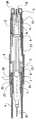
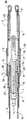
本発明は、単に一例として且つ、添付図面を参照することにより以下により詳細に説明する。添付図面の7つの図の全ては、同一の自動注射装置の縦断面図を示し、図面の各々には、異なる作用状態が示されている。 The invention will now be described in more detail by way of example only and with reference to the accompanying drawings. All seven figures of the accompanying drawings show a longitudinal section of the same automatic injection device, each showing a different working state.
一例として示した自動注射装置は、前側ケーシング部分1及び後側ケーシング部分2から成るケーシングを有しており、これら2つのケーシング部分は接続部3によって互いに接続されている。自動注射装置が再充填可能な自動注射装置であるならば、接続部3は解放可能であり、例えば、ねじ式接続部とする。しかし、自動注射装置が使い捨て型自動注射装置であるならば、接続部3は固定し、例えば融着接続部、接着剤接続部又は掛止め接続部としてよい。図面の左側にて、以下により正確に説明するように、前側ケーシング部分1内にて軸方向に変位可能である針保護管4を見ることができる。軸方向に変位可能な摺動スリーブ5は、その前端を介して針保護管4内で及びその後端に形成されたフランジ6を介して前側ケーシング部分1内で案内される。摺動スリーブ5は、アンプル様活性剤容器7を受け入れ、該容器の内部にて、ピストン8は活性剤を供給する目的のため、ピストンロッド9の助けを受けて軸方向に変位することができる。その前端活性剤容器7の前端には注射針10が設けられている。 The automatic injection device shown as an example has a casing comprising a front casing part 1 and a
係止スリーブ24の形態をした係止部材が摺動スリーブ5上で外側に取り付けられている。少なくとも1つの係止舌状体25が係止スリーブ24から弾性的に外方に突き出し、また、図1による作用状態にあるとき、針保護管4の内側ヒール部27と当接する。針保護管4に形成され且つ、係止舌状体25が内部に突き出すキャビティ26がヒール部27に接続されている。係止スリーブ24及び係止舌状体25の機能については以下に更に明確に説明する。案内スリーブ11が後側ケーシング部分2内に配置されており、該スリーブは軸方向に変位することができる。案内スリーブ11から後方に突き出し且つ、掛止め突起13を介して案内スリーブ11の一端のフランジと当接する駆動部分12が案内スリーブ11内に配置されている。駆動部分12は、ピストンロッド9に接触し且つ、駆動ばね14によってピストンロッドに対し偏倚される。 A locking member in the form of a
図1による表現において、自動注射装置は、例えば、供給時の状態のようなその係止位置にある、すなわち、意図的に又は意図せずに作用しないよう固定され且つ、汚れないように保護されている。注射針10の側部における針保護キャップ15は、この目的を果たし、また、前側ケーシング部分1及び針保護管4の上方に達する外側スリーブ16と、注射針10及び活性剤容器7の前端の上方に達する内側スリーブ17とを有しており、該容器は注射針を包み込み、シールを形成し、これにより注射針10が清浄で且つ滅菌状態にあることを保証する。更に、取り付けた針保護キャップ15は、針保護管4が接触し又は変位するのを防止することにより、自動注射装置が意図的に又は意図せずに起動されないよう固定する。 In the representation according to FIG. 1, the automatic injection device is in its locked position, for example as delivered, ie fixed so as not to act intentionally or unintentionally and protected against contamination. ing. A
その中央部に固定ピン19を備える固定キャップ18が図面の右側で自動注射装置の後端に配置されている。固定ピン19は、駆動部分の掛止め突起13の間を突き出し、このため、注射が起動されるのを確実に防止する。自動注射装置を使用すべく準備するため、針保護キャップ15及び固定キャップを除去する。針保護キャップ15が除去されるとき、内側スリーブ17と活性剤容器7との間の静止摩擦の結果として引張り力が活性剤容器7に加わることは明らかである。その結果、針保護キャップ15が除去されたとき、活性剤容器7が自動注射装置内のその位置から離れ且つ、望ましくないように前方に引っ張られるのを防止しなければならない。 A
この目的のため、掛止めスリーブ20は前側ケーシング部分に取り付けられ、該スリーブが軸方向に動くことはできないようにし、また、少なくとも1つの掛止め舌状体21が掛止めスリーブ20に配置される。掛止めスリーブの周縁の上方に分配された、掛止め舌状体21が提供されることが好ましい。図1に明確に示すように、掛止め舌状体21の自由端は、摺動スリーブ5のフランジ6と当接し、これにより、摺動スリーブ5が、該スリーブ内に配置された活性剤容器7と共に前方に引っ張られるのを防止する。 For this purpose, the
図2には、針保護キャップ15及び固定キャップ18が上述したように除去された後の自動注射装置が示されている。掛止め部材20は、依然、掛止め位置にあり、掛止め舌状体21は、注射針10と共に活性剤容器7が前方に摺動するのを防止する。更に、そのとき開放している端部にて、針保護管4は、注射針10が接触し又は注射針10に接触するのを少なくとも困難にする距離を形成する。針保護管4は、針保護管4の後端と後側ケーシング部分2との間に締め止めされるばね22の力によってこの位置に保持される。 FIG. 2 shows the automatic injection device after the
図3には、患者の皮膚に押し付けられたときの位置にあるが、未だ起動されていない自動注射装置が示されている。明確に理解し得るように、針保護管4は、図2に示した位置と比較してケーシング内に後方に変位されており、ばね22を圧縮し、注射針10の先端が患者の皮膚の僅かに上方に位置するようにする。図3にはまた、後方に変位した針保護管4が掛止め舌状体21を外方に押し、次に、該掛止め舌状体は、摺動スリーブ5のフランジ6を露呈させる状態も示されている。最後に、図2と比較したとき、針保護管4の後側部分の内部に形成されたフランジ23は次に、案内スリーブ11の前方に向けた側部と当接することが分かる。この点に関して、針保護管は、前側にて残る程度だけ前側ケーシング部分1から外方に突き出すことに注目することが重要である。しかし、図1及び図2を比較したとき、針保護管4は、係止スリーブ24を摺動スリーブ5上で多少後方に摺動させることは明らかである。 FIG. 3 shows the automatic injection device in the position when pressed against the patient's skin but not yet activated. As can be clearly seen, the
図4には、起動した瞬間の自動注射装置が示されている。図3の状態から開始して、ユーザは、自動注射装置を自分の皮膚に僅かにより強く押し付けて、針保護管4が上述の残る程度だけケーシング内に変位し、フランジ23が案内スリーブ11を上述の残る程度だけ後側ケーシング部分2内にて後方に変位させ、掛止め突起13は、後側ケーシング部分2の後端に配置された起動リング28の領域内に移動している。起動リング28は、駆動部分の弾性的なアームに形成された掛止め突起13を互いに対して十分に押して、次に、起動リング及び掛止め突起は、駆動ばね14の力によって案内スリーブ11の端部開口部を通じて引っ張られる。次に、駆動ばね14の力は、ピストンロッド9を介してピストン8に妨害されずに作用し、該ピストン8は、実際上、活性剤容器7内の液圧圧力を急激に上昇させる。この圧力は、活性剤容器を前方に摺動させ、注射針10が患者の皮膚に貫入するようにする。注射針10内の通路の直径は比較的小さいから、起動時点と注射針10が皮膚内に貫入する時点との間のこの短い時間に、注射針10から出る活性剤の量は、最大でも極めて少量である。 FIG. 4 shows the automatic injection device at the moment of activation. Starting from the state of FIG. 3, the user presses the automatic injection device slightly stronger against his skin, the
摺動スリーブ5のフランジ6が針保護管4の端部及び(又は)係止スリーブ24の端部と当接するとき、注射行程が完了する。図5及び図6には、注射針10が注射される位置にある自動注射装置が示されており、図5は、活性剤を供給し始めるときの作用状態を示し、図6は、活性剤容器7が完全に空となった状態を示す。図6による作用状態に達したとき、ユーザは、自動注射装置を引込めて、注射針10がその皮膚が除去されるようにする。 The injection stroke is completed when the
図7には、注射針10が患者の皮膚から除去されたときの作用状態が示されている。針保護管4は、自動注射装置が患者の皮膚から持ち上げられると直ちに、ばね22の力によってその当初の状態へ戻り変位している。そのとき、該針保護管は、主として、注射針を隠蔽し且つ、ユーザ及びその他の人が注射針10によって損傷されないよう保護する作用を果たす。その結果、針保護管4は注射針10に対し変位し、注射針10が針保護管4から突き出すのを防止しなければならない。この作業は、係止スリーブ24に形成された上述した係止舌状体25により行われる。針保護管4が上述したように、ばねの力によって前方に変位される間、係止スリーブ24は、摺動スリーブ5に形成された掛止め舌状体29の結果として、摺動スリーブ5におけるその位置を維持し、該摺動スリーブは、次に、図7による位置にて係止スリーブ24のキャビティ内に突き出し、これにより、係止スリーブを摺動スリーブ5上の所要位置に固定する。 FIG. 7 shows a working state when the
図7から明確に理解し得るように、次に、針保護管4の後端における係止舌状体25の自由端がその経路内に突き出し、針保護管4は、係止スリーブ24無しにて引込むことはできず、これと共に、摺動スリーブ5、また、注射針10と共に、活性剤容器7は、駆動ばね14の力に抗して、係止舌状体25を介して、前側ケーシング部分1及び後側ケーシング部分2に対し後方に変位し、注射針10は、針保護管4に対するその相対的な位置を保ち、意図的に又は意図せずに、注射針10に接触することが確実に防止される。この解決策は、針保護管4の前端を押す力の強さに関係なく、係止舌状体25により吸収すべき軸方向への力が駆動ばね14の力を上廻ることは決してないという重要な利点を有する。 As can be clearly seen from FIG. 7, the free end of the locking
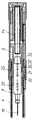
図8ないし図11には、本発明による自動注射装置の別の実施の形態が示されている。これらの図において、同一の要素及び同一の機能を果たす要素は、図1ないし図7から既知の参照番号を使用して表示されている。この実施の形態において、掛止め舌状体21は、掛止め舌状体21及び摺動スリーブ5の表面によって案内され、上記表面は、自動注射装置の長手方向軸線に対し斜めに伸びている。活性剤容器又は摺動スリーブ5を掛止めする掛止め舌状体21、及び針保護管4を掛止めする係止舌状体25は、共に、掛止めスリーブ20上に配置されている。好ましくは、掛止め舌状体21及び係止舌状体25は、掛止めスリーブ20と一体に形成されるものとする。多数の掛止め舌状体21及び係止舌状体25を係止スリーブ20上に配置することは、勿論、可能である。 8 to 11 show another embodiment of the automatic injection device according to the present invention. In these figures, identical elements and elements performing the same function are indicated using known reference numbers from FIGS. In this embodiment, the latching
図8には、掛止め舌状体21を備える掛止めスリーブ20の形態をした掛止め部材が示されており、該掛止め舌状体21は、その対面する側部に、自動注射装置の長手方向軸線に対し斜めに伸びる表面30を備えている。斜面30の先端は、掛止め舌状体21の外側部に当接する。摺動スリーブ5は、掛止め舌状体21が掛止め位置にてその内部に突き出すキャビティ31を備えている。掛止め舌状体21の斜面30に対向するキャビティ31の端縁は、掛止め舌状体21の斜面30に対し平行に伸びる斜面30´を備えている。斜面を活性剤容器7上に直接、設けることは、勿論、可能であり、このため、摺動スリーブ5は省略することが可能である。2つの斜面30、30´は、互いの上に休止する。針保護管4は、掛止めスリーブ20と摺動スリーブ5との間に少なくとも部分的に配置され、掛止め舌状体21は、針保護管4のキャビティを通って摺動スリーブ5のキャビティ31内に突き出す。針保護管4の一部分32は、斜面30、30´の当接箇所に重なり合い、掛止め舌状体21は、掛止め位置に係止される。図8において、係止舌状体25は、また、掛止め舌状体21に対向する側部にて摺動スリーブ5上にも配置されている。係止舌状体25は、針保護管4内にて該舌状体に対向するキャビティ内に突き出している。 FIG. 8 shows a latching member in the form of a latching
図3と同様に、図9には、針保護管4がケーシング1、2内に摺動した、解放位置にある自動注射装置が示されている。この位置にあるとき、針保護管4の部分32は、斜面30、30´の重なり合う領域から引き込んでいる。次に、掛止め舌状体21を針保護管4のキャビティ31内に動かすことができる。この動きは、弾性的な掛止め舌状体21の偏倚力により生じさせることができる。しかし、好ましくは、掛止め舌状体21は、斜面30に作用する駆動ばね14により加えられた圧力によりキャビティ内に外方に摺動するものとする。 Similar to FIG. 3, FIG. 9 shows the automatic injection device in the release position with the
図5と同様に、図10には、活性剤容器7がケーシング1、2に対し前進し、注射針10が組織内に注射された位置にある自動注射装置が示されている。摺動スリーブ5は、活性剤容器7と共に、掛止めスリーブ20に沿って末端方向に前進しており、掛止め舌状体21は、針保護管4のキャビティ31内で休止している。 Similar to FIG. 5, FIG. 10 shows an automatic injection device in which the
図7と同様に、図11には、自動注射装置が組織の表面から除去された後、針保護管4が注射針10を取り巻く位置にある自動注射装置が示されている。この実施の形態において、係止舌状体25は、同様に摺動スリーブ5上に配置されている。このことは、自動注射装置にて1つの構成要素を省略することを可能にする。針保護管4が前進したとき、係止舌状体25は、針保護管4の端部端縁の後方を把持し、針保護管4は、活性剤容器7又は摺動スリーブ5に対し引込まないように固定される。圧力が基端方向に向けて針保護管に加わったとき、針保護管4は、摺動スリーブ、活性剤容器7及び注射針10と共に、ケーシング1、2に対し変位する。 Similar to FIG. 7, FIG. 11 shows the automatic injection device with the
1 前側ケーシング
2 後側ケーシング
3 接続部
4 針保護管
5 摺動スリーブ
6 フランジ
7 アンプル様活性剤容器
8 ピストン
9 ピストンロッド
10 注射針
11 案内スリーブ
12 駆動部分
13 掛止め突起
14 駆動ばね
15 針保護キャップ
16 外側スリーブ
17 内側スリーブ
18 固定キャップ
19 固定ピン
20 掛止めスリーブ/掛止め部材
21 掛止め舌状体
22 ばね
23 フランジ
24 係止スリーブ
25 係止舌状体
26 キャビティ
27 内側ヒール部
28 起動リング
29 掛止め舌状体
30、30´ 斜面
31 針保護管のキャビティ
32 針保護管の一部分DESCRIPTION OF SYMBOLS 1
Claims (14)
Translated fromJapanese置。5. The automatic injection device according to claim3 or 4 , wherein the latching tongue (21) abuts a flange (6) arranged on a sliding sleeve (5) for receiving the activator container (7). To prevent the activator container (7) from being displaced with respect to the casing (1, 2), and when the needle protection tube (4) is displaced into the casing (1, 2), the needle protection tubeAn automatic injection device, wherein the latchingmember is pushed away from the flange.
The automatic injection device according to claim 6, wherein the needle protection cap (15) has an inner sleeve (17) reaching above the active agent container (7) and an outer sleeve (16) reaching above the needle protection tube (4). And an automatic injection device.
Applications Claiming Priority (1)
| Application Number | Priority Date | Filing Date | Title |
|---|---|---|---|
| CH02186/03ACH696421A5 (en) | 2003-12-18 | 2003-12-18 | Autoinjector with arresting the drug container. |
Publications (2)
| Publication Number | Publication Date |
|---|---|
| JP2005177503A JP2005177503A (en) | 2005-07-07 |
| JP4394566B2true JP4394566B2 (en) | 2010-01-06 |
Family
ID=34716065
Family Applications (1)
| Application Number | Title | Priority Date | Filing Date |
|---|---|---|---|
| JP2004367120AExpired - Fee RelatedJP4394566B2 (en) | 2003-12-18 | 2004-12-20 | Automatic injection device with a function to latch the active agent container |
Country Status (4)
| Country | Link |
|---|---|
| US (10) | US7357790B2 (en) |
| JP (1) | JP4394566B2 (en) |
| CH (1) | CH696421A5 (en) |
| DE (3) | DE102004064333B4 (en) |
Cited By (1)
| Publication number | Priority date | Publication date | Assignee | Title |
|---|---|---|---|---|
| US10238810B2 (en) | 2003-09-17 | 2019-03-26 | Elcam Medical Agricultural Cooperative Association Ltd. | Automatic injection device |
Families Citing this family (194)
| Publication number | Priority date | Publication date | Assignee | Title |
|---|---|---|---|---|
| WO2003068290A2 (en) | 2002-02-11 | 2003-08-21 | Antares Pharma, Inc. | Intradermal injector |
| US9486581B2 (en)* | 2002-09-11 | 2016-11-08 | Becton, Dickinson And Company | Injector device with force lock-out and injection rate limiting mechanisms |
| JP4339260B2 (en)* | 2002-11-25 | 2009-10-07 | テクファーマ・ライセンシング・アクチェンゲゼルシャフト | Injection device with needle protection device |
| CH696421A5 (en)* | 2003-12-18 | 2007-06-15 | Tecpharma Licensing Ag | Autoinjector with arresting the drug container. |
| GB2414409B (en) | 2004-05-28 | 2009-11-18 | Cilag Ag Int | Injection device |
| GB2414775B (en) | 2004-05-28 | 2008-05-21 | Cilag Ag Int | Releasable coupling and injection device |
| GB2414406B (en) | 2004-05-28 | 2009-03-18 | Cilag Ag Int | Injection device |
| GB2414404B (en) | 2004-05-28 | 2009-06-03 | Cilag Ag Int | Injection device |
| GB2414401B (en) | 2004-05-28 | 2009-06-17 | Cilag Ag Int | Injection device |
| GB2414403B (en) | 2004-05-28 | 2009-01-07 | Cilag Ag Int | Injection device |
| GB2414400B (en) | 2004-05-28 | 2009-01-14 | Cilag Ag Int | Injection device |
| GB2414399B (en) | 2004-05-28 | 2008-12-31 | Cilag Ag Int | Injection device |
| GB2414402B (en) | 2004-05-28 | 2009-04-22 | Cilag Ag Int | Injection device |
| GB2414405B (en) | 2004-05-28 | 2009-01-14 | Cilag Ag Int | Injection device |
| US11590286B2 (en) | 2004-11-22 | 2023-02-28 | Kaleo, Inc. | Devices, systems and methods for medicament delivery |
| US7947017B2 (en) | 2004-11-22 | 2011-05-24 | Intelliject, Inc. | Devices, systems and methods for medicament delivery |
| US7648483B2 (en) | 2004-11-22 | 2010-01-19 | Intelliject, Inc. | Devices, systems and methods for medicament delivery |
| WO2006057636A1 (en) | 2004-11-22 | 2006-06-01 | Intelliject, Llc | Devices, systems, and methods for medicament delivery |
| US10737028B2 (en) | 2004-11-22 | 2020-08-11 | Kaleo, Inc. | Devices, systems and methods for medicament delivery |
| HUE042286T2 (en) | 2005-01-24 | 2019-06-28 | Antares Pharma Inc | Needle-filled pre-filled syringe |
| US8206360B2 (en) | 2005-02-01 | 2012-06-26 | Intelliject, Inc. | Devices, systems and methods for medicament delivery |
| AU2006210865B2 (en) | 2005-02-01 | 2008-12-04 | Kaleo, Inc. | Devices, systems, and methods for medicament delivery |
| US9022980B2 (en) | 2005-02-01 | 2015-05-05 | Kaleo, Inc. | Medical injector simulation device |
| GB2427826B (en) | 2005-04-06 | 2010-08-25 | Cilag Ag Int | Injection device comprising a locking mechanism associated with integrally formed biasing means |
| GB2424838B (en) | 2005-04-06 | 2011-02-23 | Cilag Ag Int | Injection device (adaptable drive) |
| GB2425062B (en) | 2005-04-06 | 2010-07-21 | Cilag Ag Int | Injection device |
| GB2424835B (en) | 2005-04-06 | 2010-06-09 | Cilag Ag Int | Injection device (modified trigger) |
| GB2424836B (en) | 2005-04-06 | 2010-09-22 | Cilag Ag Int | Injection device (bayonet cap removal) |
| PL1759729T3 (en) | 2005-08-30 | 2010-09-30 | Cilag Gmbh Int | Needle assembly for a prefilled syringe system |
| US20110098656A1 (en)* | 2005-09-27 | 2011-04-28 | Burnell Rosie L | Auto-injection device with needle protecting cap having outer and inner sleeves |
| DE102005052460A1 (en)* | 2005-11-03 | 2007-05-16 | Tecpharma Licensing Ag | Autoinjector - Flow control for container change |
| US20070173770A1 (en) | 2006-01-23 | 2007-07-26 | The Medical House Plc | Injection device |
| GB0601309D0 (en) | 2006-01-23 | 2006-03-01 | Medical House The Plc | Injection device |
| WO2007131025A1 (en) | 2006-05-03 | 2007-11-15 | Antares Pharma, Inc. | Injector with adjustable dosing |
| WO2007131013A1 (en) | 2006-05-03 | 2007-11-15 | Antares Pharma, Inc. | Two-stage reconstituting injector |
| GB2438591B (en) | 2006-06-01 | 2011-07-13 | Cilag Gmbh Int | Injection device |
| GB2438593B (en) | 2006-06-01 | 2011-03-30 | Cilag Gmbh Int | Injection device (cap removal feature) |
| GB2438590B (en)* | 2006-06-01 | 2011-02-09 | Cilag Gmbh Int | Injection device |
| AU2013203672B2 (en)* | 2006-06-30 | 2016-04-28 | Abbvie Biotechnology Ltd | Automatic injection device |
| KR101396797B1 (en) | 2006-06-30 | 2014-05-26 | 애브비 바이오테크놀로지 리미티드 | Automatic injection device |
| WO2008047372A2 (en)* | 2006-10-19 | 2008-04-24 | Elcam Medical Agricultural Cooperative Association Ltd. | Automatic injection device |
| GB0625169D0 (en) | 2006-12-18 | 2007-01-24 | Medical House Plc The | Improved autoinjector |
| EP2125075A2 (en) | 2007-01-22 | 2009-12-02 | Intelliject, Inc. | Medical injector with compliance tracking and monitoring |
| DE102007004211A1 (en)* | 2007-01-27 | 2008-07-31 | Lts Lohmann Therapie-Systeme Ag | Disposable injector with at least one towing hook |
| GB0704351D0 (en) | 2007-03-07 | 2007-04-11 | Medical House Plc The | Improved autoinjector |
| DK2131898T3 (en)* | 2007-03-23 | 2017-10-16 | Shl Group Ab | autoinjector |
| DE102007018868A1 (en)* | 2007-04-19 | 2008-10-23 | Lts Lohmann Therapie-Systeme Ag | Disposable injector with at least one towing hook and a sliding wedge gear for unlocking releasing a locking element |
| DE102007030327A1 (en) | 2007-06-29 | 2009-01-02 | Tecpharma Licensing Ag | Injection device with a spring for a needle protection sleeve |
| CN101795720B (en)* | 2007-07-23 | 2013-05-29 | 泰尔茂株式会社 | Drug solution injector |
| GB2451662B (en)* | 2007-08-08 | 2012-09-19 | Cilag Gmbh Int | Injection device |
| GB2451664B (en)* | 2007-08-08 | 2012-06-20 | Cilag Gmbh Int | Injection device |
| GB2451666B (en)* | 2007-08-08 | 2012-08-22 | Cilag Gmbh Int | Injection device |
| GB2451665B (en)* | 2007-08-08 | 2012-09-26 | Cilag Gmbh Int | Injection device |
| GB2451663B (en)* | 2007-08-08 | 2012-09-26 | Cilag Gmbh Int | Injection device |
| US8038649B2 (en)* | 2007-09-18 | 2011-10-18 | Shl Group Ab | Automatic injection device with needle insertion |
| WO2009040602A1 (en)* | 2007-09-25 | 2009-04-02 | Becton Dickinson France | Autoinject0r with deactivating means moveable by a safety shield |
| JP5264916B2 (en)* | 2007-09-25 | 2013-08-14 | ベクトン・ディキンソン・フランス・エス.エー.エス. | Automatic syringe with deactivating means movable by safety shield |
| DK2211946T3 (en)* | 2007-09-25 | 2017-11-13 | Becton Dickinson France | AUTO INJECTOR WITH POSITIONABLE TRIGGES IN ACTIVE POSITION BY MOVING A SAFETY PROTECTION AND INDICATING THE ACTIVE POSITION |
| BRPI0817907B8 (en) | 2007-10-02 | 2021-06-22 | Lamodel Ltd | apparatus for administering a substance to an individual |
| WO2009047247A1 (en)* | 2007-10-10 | 2009-04-16 | Shl Group Ab | Medical delivery device |
| EP3636301A1 (en) | 2008-03-10 | 2020-04-15 | Antares Pharma, Inc. | Injector safety device |
| USD994111S1 (en) | 2008-05-12 | 2023-08-01 | Kaleo, Inc. | Medicament delivery device cover |
| US8021344B2 (en) | 2008-07-28 | 2011-09-20 | Intelliject, Inc. | Medicament delivery device configured to produce an audible output |
| US8052645B2 (en) | 2008-07-23 | 2011-11-08 | Avant Medical Corp. | System and method for an injection using a syringe needle |
| CA3070618C (en) | 2008-05-20 | 2021-07-20 | Avant Medical Corp. | Autoinjector system |
| US8177749B2 (en)* | 2008-05-20 | 2012-05-15 | Avant Medical Corp. | Cassette for a hidden injection needle |
| EP3263161B1 (en) | 2008-06-10 | 2020-05-06 | SHL Medical AG | Injection needle assembly |
| GB2461086B (en) | 2008-06-19 | 2012-12-05 | Cilag Gmbh Int | Injection device |
| GB2461085B (en) | 2008-06-19 | 2012-08-29 | Cilag Gmbh Int | Injection device |
| GB2461078A (en)* | 2008-06-19 | 2009-12-23 | Alice 123 Ltd | Auto injector with sliding outer sleeve |
| GB2461087B (en) | 2008-06-19 | 2012-09-26 | Cilag Gmbh Int | Injection device |
| GB2461089B (en) | 2008-06-19 | 2012-09-19 | Cilag Gmbh Int | Injection device |
| GB2461088B (en) | 2008-06-19 | 2012-09-26 | Cilag Gmbh Int | Injection device |
| GB2461084B (en) | 2008-06-19 | 2012-09-26 | Cilag Gmbh Int | Fluid transfer assembly |
| US8376993B2 (en) | 2008-08-05 | 2013-02-19 | Antares Pharma, Inc. | Multiple dosage injector |
| DE102008037310B4 (en)* | 2008-08-11 | 2023-11-16 | Ypsomed Ag | Automatic injection device for administering a fixed dose |
| GB2493432B (en)* | 2008-08-28 | 2013-04-10 | Owen Mumford Ltd | Autoinjection devices |
| GB2463034B (en)* | 2008-08-28 | 2012-11-07 | Owen Mumford Ltd | Autoinjection devices |
| GB2463071A (en)* | 2008-09-02 | 2010-03-03 | Owen Mumford Ltd | Auto-injector syringe with safety shield |
| US12097357B2 (en) | 2008-09-15 | 2024-09-24 | West Pharma. Services IL, Ltd. | Stabilized pen injector |
| US8876778B2 (en) | 2008-09-29 | 2014-11-04 | Becton Dickinson France | Injection device with retaining means actuated by needle shield |
| CN102209566B (en)* | 2008-09-29 | 2014-03-26 | 贝克顿迪金森法国公司 | Automatic injection device |
| GB0900930D0 (en)* | 2009-01-20 | 2009-03-04 | Future Injection Technologies Ltd | Injection device |
| EP2407196B1 (en)* | 2009-03-11 | 2021-02-17 | Terumo Kabushiki Kaisha | Puncture needle assembly and medicinal liquid injection device |
| KR101366427B1 (en) | 2009-03-13 | 2014-02-24 | 일라이 릴리 앤드 캄파니 | Apparatus for injecting a pharmaceutical with automatic syringe retraction following injection |
| JP5732039B2 (en) | 2009-03-20 | 2015-06-10 | アンタレス・ファーマ・インコーポレーテッド | Hazardous drug injection system |
| GB2469672B (en) | 2009-04-23 | 2013-09-25 | Medical House Ltd | Improved autoinjector |
| USD623738S1 (en)* | 2009-05-28 | 2010-09-14 | F. Hoffman La-Roche AG | Auto-injector |
| USD621929S1 (en)* | 2009-05-28 | 2010-08-17 | F. Hoffmann-La Roche Ag | Auto-injector |
| GB201017363D0 (en) | 2010-10-14 | 2010-11-24 | Owen Mumford Ltd | Injection devices |
| EP2512558A4 (en)* | 2009-12-15 | 2014-08-13 | Abbvie Biotechnology Ltd | IMPROVED TRIP PUSHER FOR AUTOMATIC INJECTION DEVICE |
| DK2536452T3 (en)* | 2010-02-18 | 2019-01-02 | Sanofi Aventis Deutschland | autoinjector |
| WO2011101382A1 (en)* | 2010-02-22 | 2011-08-25 | Sanofi-Aventis Deutschland Gmbh | Auto - injector with needle shroud and needle protection cap |
| DE102010018529A1 (en)* | 2010-04-27 | 2011-10-27 | Lts Lohmann Therapie-Systeme Ag | Disposable injector with flexurally elastic piston actuating punch |
| WO2011163511A1 (en)* | 2010-06-23 | 2011-12-29 | Tcb Medical Devices, Llc | Injector for auto-injection of medication and associated method of use |
| EP2399635A1 (en) | 2010-06-28 | 2011-12-28 | Sanofi-Aventis Deutschland GmbH | Auto-injector |
| EP2399628A1 (en)* | 2010-06-28 | 2011-12-28 | Sanofi-Aventis Deutschland GmbH | Auto-injector |
| JP6165055B2 (en)* | 2010-06-28 | 2017-07-19 | サノフィ−アベンティス・ドイチュラント・ゲゼルシャフト・ミット・ベシュレンクテル・ハフツング | Automatic syringe |
| DE102010039055A1 (en)* | 2010-08-09 | 2012-02-09 | Balluff Gmbh | Displacement measuring device |
| EP2468330A1 (en) | 2010-12-21 | 2012-06-27 | Sanofi-Aventis Deutschland GmbH | Auto-injector |
| EP2468343A1 (en)* | 2010-12-21 | 2012-06-27 | Sanofi-Aventis Deutschland GmbH | Front end for an auto-injector |
| EP2468342A1 (en)* | 2010-12-21 | 2012-06-27 | Sanofi-Aventis Deutschland GmbH | Front end for an auto-injector |
| EP2665503B1 (en)* | 2011-01-11 | 2024-01-24 | SHL Medical AG | Medicament delivery device |
| ES2710905T3 (en) | 2011-01-24 | 2019-04-29 | E3D Agricultural Coop Association Ltd | Injector |
| US8939943B2 (en) | 2011-01-26 | 2015-01-27 | Kaleo, Inc. | Medicament delivery device for administration of opioid antagonists including formulations for naloxone |
| US8627816B2 (en) | 2011-02-28 | 2014-01-14 | Intelliject, Inc. | Medicament delivery device for administration of opioid antagonists including formulations for naloxone |
| US9173999B2 (en) | 2011-01-26 | 2015-11-03 | Kaleo, Inc. | Devices and methods for delivering medicaments from a multi-chamber container |
| EP2489385A1 (en) | 2011-02-18 | 2012-08-22 | Sanofi-Aventis Deutschland GmbH | Auto-injector |
| EP2489390A1 (en)* | 2011-02-18 | 2012-08-22 | Sanofi-Aventis Deutschland GmbH | Detent mechanism |
| EP2489380A1 (en) | 2011-02-18 | 2012-08-22 | Sanofi-Aventis Deutschland GmbH | Injection device |
| EP2489388A1 (en) | 2011-02-18 | 2012-08-22 | Sanofi-Aventis Deutschland GmbH | Auto-injector |
| EP2489389A1 (en) | 2011-02-18 | 2012-08-22 | Sanofi-Aventis Deutschland GmbH | Detent mechanism |
| EP2489382A1 (en) | 2011-02-18 | 2012-08-22 | Sanofi-Aventis Deutschland GmbH | Auto-injector |
| EP2489384A1 (en) | 2011-02-18 | 2012-08-22 | Sanofi-Aventis Deutschland GmbH | Auto-injector |
| EP2489381A1 (en) | 2011-02-18 | 2012-08-22 | Sanofi-Aventis Deutschland GmbH | Auto-injector |
| EP2489386A1 (en) | 2011-02-18 | 2012-08-22 | Sanofi-Aventis Deutschland GmbH | Auto-injector |
| EP2489387A1 (en) | 2011-02-18 | 2012-08-22 | Sanofi-Aventis Deutschland GmbH | Auto-injector |
| JP5922760B2 (en)* | 2011-04-05 | 2016-05-24 | エス・ホー・エル・グループ・アクチボラゲットShl Group Ab | Drug delivery device having locking mechanism with lever |
| PL2699293T3 (en) | 2011-04-20 | 2019-08-30 | Amgen Inc. | Autoinjector apparatus |
| US9220660B2 (en) | 2011-07-15 | 2015-12-29 | Antares Pharma, Inc. | Liquid-transfer adapter beveled spike |
| US8496619B2 (en) | 2011-07-15 | 2013-07-30 | Antares Pharma, Inc. | Injection device with cammed ram assembly |
| CN103764204B (en)* | 2011-08-26 | 2016-01-20 | 伊莱利利公司 | Refill module for an injection device |
| EP2572741A1 (en)* | 2011-09-23 | 2013-03-27 | Sanofi-Aventis Deutschland GmbH | Medicament delivery device and actuation mechanism for a drug delivery device |
| JP5916884B2 (en)* | 2011-12-15 | 2016-05-11 | エス・ホー・エル・グループ・アクチボラゲットShl Group Ab | Cap assembly |
| US9486583B2 (en) | 2012-03-06 | 2016-11-08 | Antares Pharma, Inc. | Prefilled syringe with breakaway force feature |
| EP4186545A1 (en) | 2012-04-06 | 2023-05-31 | Antares Pharma, Inc. | Needle assisted jet injection administration of testosterone compositions |
| USD808010S1 (en) | 2012-04-20 | 2018-01-16 | Amgen Inc. | Injection device |
| USD898908S1 (en) | 2012-04-20 | 2020-10-13 | Amgen Inc. | Pharmaceutical product cassette for an injection device |
| US9364610B2 (en) | 2012-05-07 | 2016-06-14 | Antares Pharma, Inc. | Injection device with cammed ram assembly |
| USD715422S1 (en)* | 2012-05-18 | 2014-10-14 | Salix Pharmaceuticals, Ltd. | Automatic injection device |
| USD714932S1 (en)* | 2012-05-18 | 2014-10-07 | Radius Product Development, Inc. | Automatic injection device |
| US9522235B2 (en) | 2012-05-22 | 2016-12-20 | Kaleo, Inc. | Devices and methods for delivering medicaments from a multi-chamber container |
| GB201212190D0 (en)* | 2012-07-09 | 2012-08-22 | Oval Medical Technologies Ltd | Injector device with mechanism for preventing accidental activation |
| EP2898912B1 (en)* | 2012-09-21 | 2022-10-26 | Terumo Kabushiki Kaisha | Drug administration instrument |
| FI3659647T3 (en) | 2013-02-11 | 2024-03-28 | Antares Pharma Inc | NEEDLE-ASSISTED SPRAY INJECTOR WITH REDUCED TRIGGER FORCE |
| US8652100B1 (en) | 2013-03-08 | 2014-02-18 | Teva Pharmaceutical Industries, Ltd. | Re-useable injector device for syringe |
| US8591463B1 (en) | 2013-03-08 | 2013-11-26 | Teva Pharmaceutical Industries Ltd. | Re-useable injector device for syringe |
| CA2905031C (en) | 2013-03-11 | 2018-01-23 | Hans PFLAUMER | Dosage injector with pinion system |
| WO2014165136A1 (en) | 2013-03-12 | 2014-10-09 | Antares Pharma, Inc. | Constant volume prefilled syringes and kits thereof |
| CA2904661C (en) | 2013-03-15 | 2022-03-15 | Amgen Inc. | Drug cassette, autoinjector, and autoinjector system |
| ES2973257T3 (en) | 2013-03-15 | 2024-06-19 | Amgen Inc | Drug cassette, autoinjector and autoinjector system |
| GB2515038A (en) | 2013-06-11 | 2014-12-17 | Cilag Gmbh Int | Injection device |
| GB2515039B (en) | 2013-06-11 | 2015-05-27 | Cilag Gmbh Int | Injection Device |
| GB2517896B (en) | 2013-06-11 | 2015-07-08 | Cilag Gmbh Int | Injection device |
| GB2515032A (en) | 2013-06-11 | 2014-12-17 | Cilag Gmbh Int | Guide for an injection device |
| AT514484B1 (en)* | 2013-06-24 | 2015-05-15 | Pharma Consult Gmbh | Activator for an auto-injector |
| EP2868338A1 (en) | 2013-10-31 | 2015-05-06 | Sanofi-Aventis Deutschland GmbH | Medicament delivery device |
| USD745664S1 (en) | 2013-11-25 | 2015-12-15 | Teva Pharmaceutical Industries, Ltd. | Injector device for a syringe |
| CN106255522A (en) | 2014-05-06 | 2016-12-21 | 卡贝欧洲有限公司 | There is the delivery device of the rotator keeping plunger rod |
| US9517307B2 (en) | 2014-07-18 | 2016-12-13 | Kaleo, Inc. | Devices and methods for delivering opioid antagonists including formulations for naloxone |
| US9415176B1 (en) | 2015-01-22 | 2016-08-16 | West Pharmaceutical Services, Inc. | Autoinjector having an end-of-dose visual indicator |
| US10695495B2 (en) | 2015-03-24 | 2020-06-30 | Kaleo, Inc. | Devices and methods for delivering a lyophilized medicament |
| WO2016177393A1 (en)* | 2015-05-04 | 2016-11-10 | Lts Lohmann Therapie-Systeme Ag | Disposable injector with increased triggering reliability |
| US11068420B2 (en)* | 2015-05-12 | 2021-07-20 | Hewlett Packard Enterprise Development Lp | Scalable software stack |
| CA2990950A1 (en) | 2015-06-30 | 2017-01-05 | Kaleo, Inc. | Auto-injectors for administration of a medicament within a prefilled syringe |
| FR3039071B1 (en)* | 2015-07-24 | 2017-07-21 | Nemera La Verpilliere | AUTOMATIC LIQUID INJECTION DEVICE COMPRISING AN END SLEEVE |
| US10576207B2 (en) | 2015-10-09 | 2020-03-03 | West Pharma. Services IL, Ltd. | Angled syringe patch injector |
| US11318254B2 (en) | 2015-10-09 | 2022-05-03 | West Pharma. Services IL, Ltd. | Injector needle cap remover |
| US11116912B2 (en) | 2015-11-20 | 2021-09-14 | Shl Medical Ag | Needle shield mechanism and a medicament delivery device comprising the needle shield mechanism |
| GB201600988D0 (en)* | 2016-01-19 | 2016-03-02 | Owen Mumford Ltd | Auto-injector apparatus |
| EP3711793B1 (en) | 2016-01-21 | 2021-12-01 | West Pharma Services IL, Ltd. | A method of connecting a cartridge to an automatic injector |
| JP6885960B2 (en) | 2016-01-21 | 2021-06-16 | ウェスト ファーマ サービシーズ イスラエル リミテッド | Drug delivery device with visual indicators |
| US10646643B2 (en) | 2016-01-21 | 2020-05-12 | West Pharma. Services IL, Ltd. | Needle insertion and retraction mechanism |
| US11389597B2 (en) | 2016-03-16 | 2022-07-19 | West Pharma. Services IL, Ltd. | Staged telescopic screw assembly having different visual indicators |
| DK3452146T3 (en) | 2016-05-06 | 2024-05-27 | Shl Medical Ag | DRIVE UNIT FOR A MEDICATION DELIVERY DEVICE |
| CN109152883B (en) | 2016-05-18 | 2020-12-01 | 艾斯曲尔医疗公司 | Drug delivery mechanism for drug delivery devices |
| US10898658B2 (en) | 2016-07-06 | 2021-01-26 | LynJohnston, LLC | Compact injection device with telescoping components |
| US11338090B2 (en) | 2016-08-01 | 2022-05-24 | West Pharma. Services IL, Ltd. | Anti-rotation cartridge pin |
| JP7059251B2 (en) | 2016-08-01 | 2022-04-25 | ウェスト ファーマ サービシーズ イスラエル リミテッド | A spring that prevents the door from closing halfway |
| WO2018119218A1 (en) | 2016-12-23 | 2018-06-28 | Kaleo, Inc. | Medicament delivery device and methods for delivering drugs to infants and children |
| GB2560558A (en)* | 2017-03-15 | 2018-09-19 | Owen Mumford Ltd | Injection Device |
| WO2018167498A1 (en)* | 2017-03-15 | 2018-09-20 | Owen Mumford Limited | An injection apparatus |
| TWI668025B (en) | 2017-04-21 | 2019-08-11 | 瑞士商瑞健醫療股份有限公司 | Administration assembly for a medicament delivery device |
| EP3630226A1 (en) | 2017-05-30 | 2020-04-08 | West Pharma. Services Il, Ltd. | Modular drive train for wearable injector |
| WO2019043502A1 (en)* | 2017-09-04 | 2019-03-07 | Wockhardt Limited | Autoinjector with a needle cover |
| CA3083525A1 (en)* | 2017-12-21 | 2019-06-27 | Becton, Dickinson And Company | Device for facilitating needle injection |
| CA3088158A1 (en)* | 2018-01-10 | 2019-07-18 | LynJohnston, LLC | Compact injector systems and methods |
| US10357619B1 (en) | 2018-02-08 | 2019-07-23 | Chalbourne Brasington | Auto-injection device |
| EP3801694B1 (en)* | 2018-06-08 | 2025-08-27 | Antares Pharma, Inc. | Auto-insert injector |
| CN109331295B (en)* | 2018-11-27 | 2024-04-19 | 甘肃成纪生物药业有限公司 | Injection pen |
| KR102608702B1 (en)* | 2019-02-26 | 2023-12-01 | 벡톤 디킨슨 프랑스 | Auto-injection device with anti-tripping cap |
| CA3145580A1 (en) | 2019-08-09 | 2021-02-18 | Kaleo, Inc. | Devices and methods for delivery of substances within a prefilled syringe |
| EP4037734A1 (en)* | 2019-09-30 | 2022-08-10 | Amgen Inc. | Drug delivery device |
| US20220387714A1 (en)* | 2019-11-19 | 2022-12-08 | E3D A.C.A.L. | Emergency automatic injection device |
| US12005244B2 (en) | 2020-03-27 | 2024-06-11 | Medivena Sp. Z O.O. | Needle-based device based on direct wing-based coupling of a needle shield to a barrel thereof and safety mechanism implemented therein |
| CA3195450A1 (en)* | 2020-11-13 | 2022-05-19 | Anders Holmqvist | Medicament delivery device |
| US12268847B1 (en) | 2021-02-10 | 2025-04-08 | Kaleo, Inc. | Devices and methods for delivery of substances within a medicament container |
| CN114223939B (en)* | 2021-11-05 | 2024-06-07 | 山东将军烟草新材料科技有限公司 | Press type automatic fragrance-giving device easy to clean |
| CN115227913B (en)* | 2022-07-26 | 2023-10-20 | 南京鈊帝医疗科技有限公司 | Automatic injector and injection syringe thereof |
| US12274874B1 (en) | 2024-03-04 | 2025-04-15 | Genzyme Corporation | Injector device |
| US20250276131A1 (en) | 2024-03-04 | 2025-09-04 | Genzyme Corporation | Medicament delivery device |
| US12274873B1 (en) | 2024-03-04 | 2025-04-15 | Genzyme Corporation | Medicament delivery device |
| WO2025188598A1 (en)* | 2024-03-04 | 2025-09-12 | Genzyme Corporation | Injector device |
| US12268858B1 (en) | 2024-03-04 | 2025-04-08 | Genzyme Corporation | Injector device |
Family Cites Families (60)
| Publication number | Priority date | Publication date | Assignee | Title |
|---|---|---|---|---|
| DE289412C (en) | ||||
| US2221739A (en) | 1939-10-16 | 1940-11-12 | Reiter David | Hypodermic syringe |
| BE795162A (en)* | 1972-02-10 | 1973-08-08 | Philips Nv | INJEKTIE-INRICHTING |
| DD289412A7 (en)* | 1978-07-04 | 1991-05-02 | Arzneimittelwerk Dresden Gmbh,De | autoinjector |
| US4487602A (en)* | 1981-09-14 | 1984-12-11 | Syntex (U.S.A.) Inc. | Injection device |
| US4378015A (en)* | 1981-12-21 | 1983-03-29 | Wardlaw Stephen C | Automatic injecting syringe |
| US4801295A (en)* | 1986-05-22 | 1989-01-31 | Spencer Treesa A | Disposable hypodermic syringe and needle combination having retractable, accident preventing sheath |
| US4693708A (en)* | 1986-10-16 | 1987-09-15 | Wanderer Alan A | Combination needle shield/needle guard device for a hypodermic syringe with a permanently attached needle |
| US4902279A (en)* | 1988-10-05 | 1990-02-20 | Autoject Systems Inc. | Liquid medicament safety injector |
| US4894055A (en) | 1988-12-28 | 1990-01-16 | Sudnak Paul J | Needle guard assembly for use with hypodermic syringes and the like |
| GB8926825D0 (en)* | 1989-11-28 | 1990-01-17 | Glaxo Group Ltd | Device |
| US5271744A (en)* | 1991-04-29 | 1993-12-21 | George C. Kramer | System and method for rapid vascular drug delivery |
| US5176643A (en) | 1991-04-29 | 1993-01-05 | George C. Kramer | System and method for rapid vascular drug delivery |
| FR2691904A1 (en) | 1992-06-04 | 1993-12-10 | Applic Tech Et | Automatic syringe actuation device. |
| US5681291A (en)* | 1992-11-19 | 1997-10-28 | Tebro S.A. | Disposable auto-injector for prefilled syringes |
| EP0693946B1 (en) | 1993-03-24 | 2001-05-16 | Owen Mumford Limited | Improvements relating to injection devices |
| US5478316A (en)* | 1994-02-02 | 1995-12-26 | Becton, Dickinson And Company | Automatic self-injection device |
| US5536249A (en)* | 1994-03-09 | 1996-07-16 | Visionary Medical Products, Inc. | Pen-type injector with a microprocessor and blood characteristic monitor |
| US5637094A (en) | 1994-11-04 | 1997-06-10 | Pos-T-Vac, Inc. | Multiple dosage syringe |
| FR2733155B1 (en)* | 1995-04-18 | 1997-09-19 | Tebro | RECHARGEABLE SELF-INJECTOR |
| US5658259A (en)* | 1995-10-19 | 1997-08-19 | Meridian Medical Technologies, Inc. | Dental cartridge assembly auto-injector with protective needle cover |
| US5609577A (en)* | 1996-01-29 | 1997-03-11 | Haber; Terry M. | Automatically locking hypodermic needle hiding shield for a dose metering syringe |
| DE29801168U1 (en)* | 1998-01-24 | 1999-08-12 | Medico Dev Investment Co | Injection device |
| FR2774294B1 (en)* | 1998-02-04 | 2000-04-14 | Marc Brunel | DEVICE FOR AUTOMATICALLY INJECTING A DOSE OF MEDICINAL PRODUCT |
| DE19821933C1 (en)* | 1998-05-15 | 1999-11-11 | Disetronic Licensing Ag | Device for administering an injectable product |
| DE19822031C2 (en) | 1998-05-15 | 2000-03-23 | Disetronic Licensing Ag | Auto injection device |
| SE9803662D0 (en)* | 1998-10-26 | 1998-10-26 | Pharmacia & Upjohn Ab | autoinjector |
| DE19925904C1 (en)* | 1999-06-07 | 2001-02-01 | Disetronic Licensing Ag | Unit for subcutaneous application of an injectable product comprises a system which indicates whether the protection sleeve of the injection needle is in its fully retracted position |
| DE10009814B4 (en)* | 2000-03-01 | 2008-03-06 | Tecpharma Licensing Ag | Disposable injector |
| US6607508B2 (en) | 2000-04-27 | 2003-08-19 | Invivotech, Inc. | Vial injector device |
| US20030036725A1 (en)* | 2000-09-21 | 2003-02-20 | Gilad Lavi | Reconstitution and injection system |
| DE10060373A1 (en)* | 2000-12-05 | 2002-06-06 | Basf Ag | Reactively modified, particulate polymers for treating the surfaces of textile and non-textile materials |
| SE518981C2 (en) | 2000-12-14 | 2002-12-17 | Shl Medical Ab | autoinjector |
| GB0118419D0 (en)* | 2001-07-28 | 2001-09-19 | Owen Mumford Ltd | Improvements relating to injection devices |
| US20030105430A1 (en)* | 2001-11-30 | 2003-06-05 | Elan Pharma International Limited Wil House | Automatic injector |
| US7004929B2 (en)* | 2002-03-29 | 2006-02-28 | Mdc Investment Holdings, Inc. | Safety pre-filled cartridge injector |
| US6979316B1 (en) | 2002-05-23 | 2005-12-27 | Seedlings Life Science Ventures Llc | Apparatus and method for rapid auto-injection of medication |
| JP4448448B2 (en) | 2002-09-24 | 2010-04-07 | エス・ホー・エル・グループ・アクチボラゲット | Injection device |
| JP4339260B2 (en)* | 2002-11-25 | 2009-10-07 | テクファーマ・ライセンシング・アクチェンゲゼルシャフト | Injection device with needle protection device |
| US7252651B2 (en)* | 2003-01-07 | 2007-08-07 | Becton, Dickinson And Company | Disposable injection device |
| US6767336B1 (en)* | 2003-01-09 | 2004-07-27 | Sheldon Kaplan | Automatic injector |
| DE10320225A1 (en)* | 2003-05-05 | 2004-12-02 | L + N Plast-Vertriebs Gmbh | Reusable actuator for a sterile syringe |
| US6805686B1 (en)* | 2003-05-06 | 2004-10-19 | Abbott Laboratories | Autoinjector with extendable needle protector shroud |
| DE10339794A1 (en)* | 2003-08-28 | 2005-04-07 | Tecpharma Licensing Ag | Administering device with a protective cap removal device and a needle protection sleeve blocking device |
| DE10342058B4 (en) | 2003-09-11 | 2007-10-25 | Tecpharma Licensing Ag | Administration device for an injectable product with a trigger safety device |
| DE10348185A1 (en) | 2003-10-16 | 2005-05-19 | Tecpharma Licensing Ag | Injection device for administering fluid product e.g. insulin, comprising injection needle and needle cover arranged on holder or on casing so that it can shift and generally surrounds injection needle in advanced position |
| DE10351594A1 (en) | 2003-11-05 | 2005-06-16 | Tecpharma Licensing Ag | Device for the administration of an injectable product |
| DE10351598A1 (en) | 2003-11-05 | 2005-06-16 | Tecpharma Licensing Ag | Auto-injection device |
| US20050101919A1 (en) | 2003-11-07 | 2005-05-12 | Lennart Brunnberg | Device for an injector |
| CH696519A5 (en)* | 2003-12-03 | 2007-07-31 | Tecpharma Licensing Ag | Automatic injection unit comprises at least one elastic element which during an injection is displaced so that entry of the needle protection sleeve after the injection into the housing is no longer possible |
| CH696421A5 (en)* | 2003-12-18 | 2007-06-15 | Tecpharma Licensing Ag | Autoinjector with arresting the drug container. |
| GB2414401B (en) | 2004-05-28 | 2009-06-17 | Cilag Ag Int | Injection device |
| ES2557778T3 (en) | 2004-11-24 | 2016-01-28 | Group Ab Shl | Injection device |
| HUE042286T2 (en) | 2005-01-24 | 2019-06-28 | Antares Pharma Inc | Needle-filled pre-filled syringe |
| DE102005007614A1 (en) | 2005-02-18 | 2006-08-24 | Tecpharma Licensing Ag | Auto-injector with a release lock |
| FR2884721A1 (en) | 2005-04-20 | 2006-10-27 | Becton Dickinson France Soc Pa | Assistance device for device of injection of a product, comprises hollow body for receiving the product, hollow injection needle for penetrating into injection site, piston placed in the body, hollow sleeve with bearing surface |
| US7955304B2 (en) | 2005-07-15 | 2011-06-07 | Shl Group Ab | Injector |
| WO2007099044A1 (en) | 2006-03-03 | 2007-09-07 | Shl Medical Ab | Medical device with orientation sensitive priming mechanism |
| ES2365931T3 (en) | 2006-12-13 | 2011-10-13 | Shl Group Ab | AUTOMATIC INJECTOR |
| DE102007030327A1 (en) | 2007-06-29 | 2009-01-02 | Tecpharma Licensing Ag | Injection device with a spring for a needle protection sleeve |
- 2003
- 2003-12-18CHCH02186/03Apatent/CH696421A5/ennot_activeIP Right Cessation
- 2004
- 2004-12-14DEDE102004064333.4Apatent/DE102004064333B4/ennot_activeExpired - Lifetime
- 2004-12-14DEDE102004064159.5Apatent/DE102004064159B4/ennot_activeExpired - Lifetime
- 2004-12-14DEDE102004060146.1Apatent/DE102004060146C5/ennot_activeExpired - Fee Related
- 2004-12-17USUS11/016,539patent/US7357790B2/ennot_activeExpired - Lifetime
- 2004-12-20JPJP2004367120Apatent/JP4394566B2/ennot_activeExpired - Fee Related
- 2007
- 2007-08-09USUS11/836,503patent/US8409149B2/enactiveActive
- 2013
- 2013-04-01USUS13/854,425patent/US8945049B2/ennot_activeExpired - Fee Related
- 2014
- 2014-12-22USUS14/579,064patent/US9427528B2/ennot_activeExpired - Fee Related
- 2016
- 2016-08-26USUS15/248,192patent/US9855392B2/ennot_activeExpired - Lifetime
- 2017
- 2017-11-29USUS15/825,828patent/US10493213B2/ennot_activeExpired - Lifetime
- 2019
- 2019-10-21USUS16/658,378patent/US10973988B2/ennot_activeExpired - Lifetime
- 2020
- 2020-06-11USUS16/898,725patent/US10960143B2/ennot_activeExpired - Fee Related
- 2021
- 2021-03-03USUS17/191,127patent/US11426529B2/ennot_activeExpired - Lifetime
- 2022
- 2022-08-26USUS17/896,452patent/US12268857B2/enactiveActive
Cited By (1)
| Publication number | Priority date | Publication date | Assignee | Title |
|---|---|---|---|---|
| US10238810B2 (en) | 2003-09-17 | 2019-03-26 | Elcam Medical Agricultural Cooperative Association Ltd. | Automatic injection device |
Also Published As
| Publication number | Publication date |
|---|---|
| US20050203466A1 (en) | 2005-09-15 |
| US20200338274A1 (en) | 2020-10-29 |
| DE102004060146C5 (en) | 2015-12-31 |
| DE102004064159B4 (en) | 2020-08-13 |
| US10493213B2 (en) | 2019-12-03 |
| DE102004064333B4 (en) | 2024-01-11 |
| US20150112273A1 (en) | 2015-04-23 |
| US20210236733A1 (en) | 2021-08-05 |
| US10960143B2 (en) | 2021-03-30 |
| US11426529B2 (en) | 2022-08-30 |
| US20200046909A1 (en) | 2020-02-13 |
| US20080015520A1 (en) | 2008-01-17 |
| US20130218094A1 (en) | 2013-08-22 |
| DE102004060146A1 (en) | 2005-08-04 |
| CH696421A5 (en) | 2007-06-15 |
| US8945049B2 (en) | 2015-02-03 |
| US9855392B2 (en) | 2018-01-02 |
| US7357790B2 (en) | 2008-04-15 |
| US8409149B2 (en) | 2013-04-02 |
| JP2005177503A (en) | 2005-07-07 |
| US20180078713A1 (en) | 2018-03-22 |
| US20160361502A1 (en) | 2016-12-15 |
| US9427528B2 (en) | 2016-08-30 |
| US10973988B2 (en) | 2021-04-13 |
| US20230069270A1 (en) | 2023-03-02 |
| DE102004060146B4 (en) | 2009-09-03 |
| US12268857B2 (en) | 2025-04-08 |
Similar Documents
| Publication | Publication Date | Title |
|---|---|---|
| JP4394566B2 (en) | Automatic injection device with a function to latch the active agent container | |
| US11617827B2 (en) | Invisible needle | |
| JP5442611B2 (en) | Infusion device with locking mechanism for syringe carrier | |
| JP5372932B2 (en) | Injection device | |
| US9180256B2 (en) | Sheath removal apparatus | |
| JP4299466B2 (en) | Needle-assisted jet injector | |
| US12133974B2 (en) | Safety housing based implant/medicament injecting system | |
| JP2738514B2 (en) | Automatic injection device | |
| CN101815549B (en) | Injection device | |
| JP2007521845A (en) | Injection device with needle cover | |
| TW202026022A (en) | Injection device with commit feature | |
| KR19980018907A (en) | Non-dosing cartridege for an injection device | |
| KR20100057617A (en) | Injection device with locking mechanism for syringe carrier | |
| TW201231120A (en) | Finger guard for an injection device | |
| JP2007514486A (en) | Hypodermic syringe | |
| TW202245855A (en) | Injection device | |
| JP2008510547A (en) | Needle protection device and injection device having the same |
Legal Events
| Date | Code | Title | Description |
|---|---|---|---|
| A131 | Notification of reasons for refusal | Free format text:JAPANESE INTERMEDIATE CODE: A131 Effective date:20080225 | |
| A601 | Written request for extension of time | Free format text:JAPANESE INTERMEDIATE CODE: A601 Effective date:20080526 | |
| A602 | Written permission of extension of time | Free format text:JAPANESE INTERMEDIATE CODE: A602 Effective date:20080529 | |
| A521 | Request for written amendment filed | Free format text:JAPANESE INTERMEDIATE CODE: A523 Effective date:20080825 | |
| A131 | Notification of reasons for refusal | Free format text:JAPANESE INTERMEDIATE CODE: A131 Effective date:20090306 | |
| A521 | Request for written amendment filed | Free format text:JAPANESE INTERMEDIATE CODE: A523 Effective date:20090526 | |
| TRDD | Decision of grant or rejection written | ||
| A01 | Written decision to grant a patent or to grant a registration (utility model) | Free format text:JAPANESE INTERMEDIATE CODE: A01 Effective date:20090916 | |
| A01 | Written decision to grant a patent or to grant a registration (utility model) | Free format text:JAPANESE INTERMEDIATE CODE: A01 | |
| A61 | First payment of annual fees (during grant procedure) | Free format text:JAPANESE INTERMEDIATE CODE: A61 Effective date:20091015 | |
| R150 | Certificate of patent or registration of utility model | Ref document number:4394566 Country of ref document:JP Free format text:JAPANESE INTERMEDIATE CODE: R150 Free format text:JAPANESE INTERMEDIATE CODE: R150 | |
| FPAY | Renewal fee payment (event date is renewal date of database) | Free format text:PAYMENT UNTIL: 20121023 Year of fee payment:3 | |
| FPAY | Renewal fee payment (event date is renewal date of database) | Free format text:PAYMENT UNTIL: 20121023 Year of fee payment:3 | |
| FPAY | Renewal fee payment (event date is renewal date of database) | Free format text:PAYMENT UNTIL: 20131023 Year of fee payment:4 | |
| R250 | Receipt of annual fees | Free format text:JAPANESE INTERMEDIATE CODE: R250 | |
| R250 | Receipt of annual fees | Free format text:JAPANESE INTERMEDIATE CODE: R250 | |
| R250 | Receipt of annual fees | Free format text:JAPANESE INTERMEDIATE CODE: R250 | |
| R250 | Receipt of annual fees | Free format text:JAPANESE INTERMEDIATE CODE: R250 | |
| R250 | Receipt of annual fees | Free format text:JAPANESE INTERMEDIATE CODE: R250 | |
| R250 | Receipt of annual fees | Free format text:JAPANESE INTERMEDIATE CODE: R250 | |
| R250 | Receipt of annual fees | Free format text:JAPANESE INTERMEDIATE CODE: R250 | |
| R250 | Receipt of annual fees | Free format text:JAPANESE INTERMEDIATE CODE: R250 | |
| R250 | Receipt of annual fees | Free format text:JAPANESE INTERMEDIATE CODE: R250 | |
| S111 | Request for change of ownership or part of ownership | Free format text:JAPANESE INTERMEDIATE CODE: R313113 | |
| R350 | Written notification of registration of transfer | Free format text:JAPANESE INTERMEDIATE CODE: R350 | |
| R250 | Receipt of annual fees | Free format text:JAPANESE INTERMEDIATE CODE: R250 | |
| R250 | Receipt of annual fees | Free format text:JAPANESE INTERMEDIATE CODE: R250 | |
| LAPS | Cancellation because of no payment of annual fees |