JP4393762B2 - Database processing method and apparatus and processing program therefor - Google Patents
Database processing method and apparatus and processing program thereforDownload PDFInfo
- Publication number
- JP4393762B2 JP4393762B2JP2002368688AJP2002368688AJP4393762B2JP 4393762 B2JP4393762 B2JP 4393762B2JP 2002368688 AJP2002368688 AJP 2002368688AJP 2002368688 AJP2002368688 AJP 2002368688AJP 4393762 B2JP4393762 B2JP 4393762B2
- Authority
- JP
- Japan
- Prior art keywords
- database
- log information
- host computer
- log
- subsystem
- Prior art date
- Legal status (The legal status is an assumption and is not a legal conclusion. Google has not performed a legal analysis and makes no representation as to the accuracy of the status listed.)
- Expired - Fee Related
Links
Images


Classifications
- G—PHYSICS
- G06—COMPUTING OR CALCULATING; COUNTING
- G06F—ELECTRIC DIGITAL DATA PROCESSING
- G06F11/00—Error detection; Error correction; Monitoring
- G06F11/07—Responding to the occurrence of a fault, e.g. fault tolerance
- G06F11/16—Error detection or correction of the data by redundancy in hardware
- G06F11/20—Error detection or correction of the data by redundancy in hardware using active fault-masking, e.g. by switching out faulty elements or by switching in spare elements
- G06F11/2097—Error detection or correction of the data by redundancy in hardware using active fault-masking, e.g. by switching out faulty elements or by switching in spare elements maintaining the standby controller/processing unit updated
- G—PHYSICS
- G06—COMPUTING OR CALCULATING; COUNTING
- G06F—ELECTRIC DIGITAL DATA PROCESSING
- G06F11/00—Error detection; Error correction; Monitoring
- G06F11/07—Responding to the occurrence of a fault, e.g. fault tolerance
- G06F11/14—Error detection or correction of the data by redundancy in operation
- G06F11/1402—Saving, restoring, recovering or retrying
- G06F11/1471—Saving, restoring, recovering or retrying involving logging of persistent data for recovery
- G—PHYSICS
- G06—COMPUTING OR CALCULATING; COUNTING
- G06F—ELECTRIC DIGITAL DATA PROCESSING
- G06F11/00—Error detection; Error correction; Monitoring
- G06F11/07—Responding to the occurrence of a fault, e.g. fault tolerance
- G06F11/16—Error detection or correction of the data by redundancy in hardware
- G06F11/20—Error detection or correction of the data by redundancy in hardware using active fault-masking, e.g. by switching out faulty elements or by switching in spare elements
- G06F11/2053—Error detection or correction of the data by redundancy in hardware using active fault-masking, e.g. by switching out faulty elements or by switching in spare elements where persistent mass storage functionality or persistent mass storage control functionality is redundant
- G06F11/2094—Redundant storage or storage space
- Y—GENERAL TAGGING OF NEW TECHNOLOGICAL DEVELOPMENTS; GENERAL TAGGING OF CROSS-SECTIONAL TECHNOLOGIES SPANNING OVER SEVERAL SECTIONS OF THE IPC; TECHNICAL SUBJECTS COVERED BY FORMER USPC CROSS-REFERENCE ART COLLECTIONS [XRACs] AND DIGESTS
- Y10—TECHNICAL SUBJECTS COVERED BY FORMER USPC
- Y10S—TECHNICAL SUBJECTS COVERED BY FORMER USPC CROSS-REFERENCE ART COLLECTIONS [XRACs] AND DIGESTS
- Y10S707/00—Data processing: database and file management or data structures
- Y10S707/99941—Database schema or data structure
- Y10S707/99944—Object-oriented database structure
- Y10S707/99945—Object-oriented database structure processing
- Y—GENERAL TAGGING OF NEW TECHNOLOGICAL DEVELOPMENTS; GENERAL TAGGING OF CROSS-SECTIONAL TECHNOLOGIES SPANNING OVER SEVERAL SECTIONS OF THE IPC; TECHNICAL SUBJECTS COVERED BY FORMER USPC CROSS-REFERENCE ART COLLECTIONS [XRACs] AND DIGESTS
- Y10—TECHNICAL SUBJECTS COVERED BY FORMER USPC
- Y10S—TECHNICAL SUBJECTS COVERED BY FORMER USPC CROSS-REFERENCE ART COLLECTIONS [XRACs] AND DIGESTS
- Y10S707/00—Data processing: database and file management or data structures
- Y10S707/99941—Database schema or data structure
- Y10S707/99948—Application of database or data structure, e.g. distributed, multimedia, or image
Landscapes
- Engineering & Computer Science (AREA)
- Theoretical Computer Science (AREA)
- Quality & Reliability (AREA)
- Physics & Mathematics (AREA)
- General Engineering & Computer Science (AREA)
- General Physics & Mathematics (AREA)
- Information Retrieval, Db Structures And Fs Structures Therefor (AREA)
Abstract
Description
Translated fromJapanese【0001】
【発明の属する技術分野】
本発明はホストコンピュータと記憶装置サブシステムとを接続してデータベース処理を行うデータベース処理システムに関し、特にホストコンピュータのデータベース処理の内容を示すログ情報により、記憶装置サブシステム内のデータベースにデータベース処理内容を反映するデータベース処理システムに適用して有効な技術に関するものである。
【0002】
【従来の技術】
従来のデータベース管理システムでは、ホストコンピュータ上と記憶装置サブシステムとの間でデータベースブロック及びログブロックの入出力を行っている。すなわち、データベース管理システムが入出力の効率を向上させる為にホストコンピュータのメインメモリ上にデータベースのバッファを設定し、当該バッファ上に記憶装置(メインメモリと比較して低速で大容量の磁気ディスク装置等の記憶装置を指すものとする)から入力したデータベースブロックをキャッシングすることによって、できるだけ記憶装置からの入出力を削減している。
【0003】
この様なデータベース管理システムでは、データの更新処理については、予めデータベースバッファ上に入力したデータベースブロックに対して行い、その際の更新履歴情報をログ専用のバッファにログとして書き出した後、トランザクションの決着時にそのログを記憶装置に強制出力することによって整合性を保証している。その際、データベースブロックの記憶装置への反映(書き込み)では、当該ブロックに対して行った更新履歴ログを先行して記憶装置に出力する、所謂WAL(Write Ahead Log)を遵守する必要がある。
【0004】
また、データベース管理システムでは、障害に備え、定期的にDBの整合性を保証する為、稼動中にチェックポイントを取得する。チェックポイントは、システム障害時の再開始処理を行う起点となるデータベースの整合性が保証されたポイントとなる。主にチェックポイントは稼動中に出力したログブロック数がある一定の回数に達した時点に取得する場合が多い。チェックポイント処理では、その時点のデータベースバッファ上の更新が行われたデータベースブロックを記憶装置上に全て書き出す処理が行われる(例えば非特許文献1参照)。
【0005】
【非特許文献1】
ジム・グレイ(Jim Gray)、アンドレアス・ロイター(Andreas Reuter)著、「トランザクション・プロセッシング:コンセプト・アンド・テクニック(TRANSACTION PROCESSING:CONCEPTS AND TECHNIQUES)」(米国)、第1版、モーガン・カウフマン・パブリッシャー(MORGAN KAUFMAN PUBLISHERS)社発行、1993年、pp.556-557、pp.604-609
【0006】
【発明が解決しようとする課題】
従来のデータベース管理システムにおけるデータベースブロックの記憶装置への書き込み方法では、前記の様にデータベースバッファ上の更新が行われたデータベースブロックを記憶装置上に全て書き出す処理が行われるが、更新が行われたデータベースブロック中には更新の行われていないレコードも含まれている為、必要の無い入出力も発生し、ホストコンピュータと記憶装置サブシステムとの間の入出力処理に大きな負荷がかかるという問題がある。
【0007】
本発明の目的は上記問題を解決し、ホストコンピュータのバッファ上で行われたデータベース処理の内容を記憶装置サブシステム上のデータベース領域へ反映させる際に、ホストコンピュータと記憶装置サブシステムとの間の入出力処理負荷を低減させることが可能な技術を提供することにある。
【0008】
本発明の他の目的は、ホストコンピュータの障害回復処理時に記憶装置サブシステムのキャッシュメモリ上に上記データベースの反映データが格納されているため、上記回復処理を高速に実行することができる技術を提供することにある。
【0009】
本発明の他の目的はホストコンピュータのバッファ上で行われたデータベース処理の内容をログ情報によって記憶装置サブシステム上のデータベース領域へ反映させる際に、不要な入出力処理を省略することが可能な技術を提供することにある。
【0010】
本発明の他の目的はホストコンピュータのバッファ上で行われたデータベース処理の内容をログ情報によって記憶装置サブシステム上のデータベース領域へ反映させる際に、その処理を効率的に行うことが可能な技術を提供することにある。
【0011】
本発明の他の目的は複数台の記憶装置サブシステムにデータベース領域を配置している大規模なデータベース処理システムで、ホストコンピュータのバッファ上で行われたデータベース処理の内容を記憶装置サブシステム上のデータベース領域へ反映させる際にも、ホストコンピュータと記憶装置サブシステムとの間の入出力処理負荷を低減させることが可能な技術を提供することにある。
【0012】
【課題を解決するための手段】
本発明は、ホストコンピュータのバッファ上で行われたデータベース処理の内容を記憶装置上のデータベースに反映させる処理を行うデータベース処理システムにおいて、ホストコンピュータで行われたデータベース処理の内容を示すログ情報に従って記憶装置サブシステム上のデータベース領域のデータへデータベース処理内容を反映するものである。
【0013】
本発明のデータベース処理システムでは、記憶装置サブシステム内のデータベース領域の内容を一時的に保持するデータベースバッファと、データベースバッファに対する更新処理の内容を一時的に保持するログバッファとをホストコンピュータに備えており、ホストコンピュータでのデータベース処理の実行に伴ってデータベースバッファの内容が変更され、その変更内容を記憶装置サブシステム内のデータベース領域に反映させる必要が生じた場合には、データベースバッファ上で行われた更新処理の内容を示すログ情報の記憶装置サブシステムへの書き込みを要求するアクセス要求をホストコンピュータから記憶装置サブシステムへ送信する。
【0014】
記憶装置サブシステムでは、前記アクセス要求をホストコンピュータから受信し、その受信したアクセス要求が書き込み要求または読み込み要求のいずれであるかを判定する。そして、その受信したアクセス要求が書き込み要求である場合には、その書き込み内容がホストコンピュータで行われたデータベース処理の内容を示すログ情報であるかどうかを判定する。
【0015】
前記判定の結果、その書き込み内容が前記ログ情報である場合には、ホストコンピュータ側のデータベース処理で認識している論理的な位置情報と記憶装置サブシステム上の物理的な位置情報との対応関係を示す変換テーブルを参照し、前記ログ情報中に示された位置情報を記憶装置サブシステム上の物理的な位置情報に変換した後、その変換した物理的な位置情報で表される記憶装置サブシステム上のデータベース領域のデータを前記ログ情報の内容に従って更新する。
【0016】
そのときに、記憶装置サブシステムのキャッシュメモリに当該反映対象データが格納されている場合には、キャッシュメモリに格納されている当該反映対象データを反映する。キャッシュメモリに格納されていない場合は、キャッシュメモリに反映対象データをアップロードし、その後、上記反映対象データをキャッシュメモリに格納する。
【0017】
またホストコンピュータは、データベースバッファ中にデータベース処理でアクセス対象となっているデータが存在していない場合に、当該データの読み込み要求をホストコンピュータから記憶装置サブシステムへ送信し、記憶装置サブシステムは、ホストコンピュータから受信したアクセス要求が読み込み要求である場合には、それ以前の書き込み要求で受信したログ情報中に、読み込み対象のデータを更新するログ情報が含まれているかどうかを判定し、そのログ情報中に読み込み対象のデータを更新するログ情報が含まれている場合には、読み込み対象のデータを当該ログ情報の内容に従って更新してホストコンピュータ側へ送信する。
【0018】
前記の様に本発明では、データベースバッファの内容を記憶装置サブシステム内のデータベース領域に反映させる必要が生じた場合に、更新処理の行われたレコードを1つでも含むデータベースブロック全てをホストコンピュータから記憶装置サブシステムへ送信するのではなく、データベースバッファに対する更新処理の内容を示すログ情報をホストコンピュータから記憶装置サブシステムへ送信するので、ホストコンピュータと記憶装置サブシステムとの間で送信されるデータ量を減少させることができる。
【0019】
以上の様に本発明のデータベース処理システムによれば、ホストコンピュータのバッファ上で行われたデータベース処理の内容を示すログ情報に従って記憶装置サブシステム上のデータベース領域のデータを更新するので、ホストコンピュータのバッファ上で行われたデータベース処理の内容を記憶装置サブシステム上のデータベース領域へ反映させる際に、ホストコンピュータと記憶装置サブシステムとの間の入出力処理負荷を低減させることが可能である。
【0020】
【発明の実施の形態】
(実施形態1)
以下にホストコンピュータのバッファ上で行われたデータベース処理の内容をディスクサブシステムの磁気ディスク装置上のデータベースに反映させる処理を行う実施形態1のデータベース処理システムについて説明する。
【0021】
図1は本実施形態のデータベース処理システムのシステム構成を示す図である。図1に示す様に本実施形態のホストコンピュータ1はデータベース管理処理部10を有している。データベース管理処理部10は、ホストコンピュータ1のDBバッファ12の内容をディスクサブシステム2内の磁気ディスク装置へ反映させる必要が生じた場合に、そのDBバッファ12に対して行われたデータベース処理の内容を示すログ情報であるログブロック262aの書き込み要求をホストコンピュータ1からディスクサブシステム2へ送信し、DBバッファ12中にデータベース処理でアクセス対象となっているデータが存在していない場合に当該データの読み込み要求をホストコンピュータ1からディスクサブシステム2へ送信する処理部である。
【0022】
ホストコンピュータ1をデータベース管理処理部10として機能させる為のプログラムは、CD−ROM等の記録媒体に記録され磁気ディスク等に格納された後、メモリにロードされて実行されるものとする。なお前記プログラムを記録する記録媒体はCD−ROM以外の他の記録媒体でも良い。また前記プログラムを当該記録媒体から情報処理装置にインストールして使用しても良いし、ネットワークを通じて当該記録媒体にアクセスして前記プログラムを使用するものとしても良い。
またディスクサブシステム2は、ディスク制御処理部21と、ディスクアクセス制御部23と、更新処理部30とを有している。
【0023】
ディスク制御処理部21は、ホストコンピュータ1から送信されたアクセス要求を受信し、その受信したアクセス要求が書き込み要求または読み込み要求のいずれであるかを判定する処理や、ディスクサブシステム装置全体の動作を制御する制御処理部である。
【0024】
ディスクアクセス制御部23は、ディスクサブシステム2配下の各磁気ディスク装置へのアクセスを制御する処理部である。更新処理部30は、前記受信したアクセス要求が書き込み要求である場合に、その書き込み内容がホストコンピュータ1のDBバッファ12上で行われたデータベース処理の内容を示すログ情報であるかどうかを判定し、前記書き込み内容が前記ログ情報である場合に、ホストコンピュータ1側のデータベース処理で認識している論理的な位置情報とディスクサブシステム2上の物理的な位置情報との対応関係を示すDB−ディスクブロック変換テーブル28によって、前記ログ情報中に示された位置情報をディスクサブシステム2上の物理的な位置情報に変換し、その変換した物理的な位置情報で表されるディスクサブシステム2上のデータベース領域24のデータを前記ログ情報の内容に従って更新する処理部である。
【0025】
ディスクサブシステム2を、ディスク制御処理部21、ディスクアクセス制御部23及び更新処理部30として機能させる為のプログラムは、フロッピーディスク等の記録媒体に記録されて実行されるものとする。なお前記プログラムを記録する記録媒体はフロッピーディスク以外の他の記録媒体でも良い。また前記プログラムを当該記録媒体から情報処理装置にインストールして使用しても良いし、ネットワークを通じて当該記録媒体にアクセスして前記プログラムを使用するものとしても良い。
【0026】
本実施形態のホストコンピュータ1とディスクサブシステム2は、ストレージエリアネットワーク16で接続されている。
ホストコンピュータ1では、データベース管理処理部10が稼動し、ホストコンピュータ1は、ディスクサブシステム2内のデータベース領域24の内容を一時的に保持するDBバッファ12と、DBバッファ12に対する更新処理の内容を一時的に保持するログバッファ14とを備えている。
【0027】
ディスクサブシステム2では、ホストコンピュータ1からの命令を受けて動作するディスク制御処理部21と、キャッシュメモリ22と、ディスクアクセス制御部23とを通して磁気ディスク装置上のデータベース領域24へのアクセスが行われており、ディスクアクセスは常にキャッシュメモリ22を介して行われることになる。
【0028】
本実施形態では、ホストコンピュータ1上のデータベース管理処理部10で動作するトランザクションによって更新されたデータの更新履歴情報であるログ情報がログブロック262aに書き込まれ、トランザクションの決着時等、DBバッファ12の内容をディスクサブシステム2へ反映させる必要が生じた場合に、ログブロック262aがディスクサブシステム2に書き込まれる。
【0029】
本実施形態の更新処理部30は、データの書き込みが行われると、そのデータがログブロック262aであるかどうかを判定し、ディスクサブシステム2上でデータベースブロック242aの書き込みを制御する。
【0030】
すなわち更新処理部30は、ディスクサブシステム2が受け付けたコマンドを解析し、ログブロック262aの書き込み要求であれば、キャッシュメモリ22上に書き込んだログブロック262aを解析し、ログブロック262a中のログレコードから該当するデータベース領域24のデータベースブロック242aをキャッシュメモリ22上にアップロードし、ログの内容を反映する処理を行う。
【0031】
このとき反映されるデータベースブロック242aは、ログブロック262a中のログレコードではホストコンピュータ1上のデータベース管理処理部10が認識できる論理的な位置情報で表されている為、この論理的な位置情報をディスクサブシステム2上の物理的な位置情報にマッピングする必要がある。そこで、この処理をDB−ディスクブロック変換テーブル28を用いて行う。DB−ディスクブロック変換テーブル28は、一般的にはDB構築時にホストコンピュータ1上のデータベース管理処理部10から作成されることになる。
【0032】
図2は本実施形態のDB−ディスクブロック変換テーブル28の構成情報を示す図である。図2に示す様にDB−ディスクブロック変換テーブル28は、データベース領域24を識別する為の情報であるデータベース領域IDと、そのデータベース領域IDで識別されるデータベース領域が複数のファイルで構成される場合のファイルの順序番号を示すファイルIDと、前記データベース領域を構成するブロックの長さを示すブロック長と、前記データベース領域の構成ファイルが確保されている論理ボリュームを識別する為の情報である論理ボリュームIDと、その論理ボリュームIDで識別される論理ボリュームがマッピングされているディスクサブシステムを識別する為の番号であるディスク制御装置番号と、そのディスク制御装置番号で識別されるディスクサブシステムの磁気ディスク装置の内で、前記論理ボリュームがマッピングされている磁気ディスク装置のドライブ番号を識別する為の情報である物理デバイスIDと、その物理デバイスIDで識別される磁気ディスク装置上での当該ファイルの相対的な位置を示す相対位置とを格納している。
【0033】
データベース領域24を構成するファイルは、ホストコンピュータ1上のオペレーティングシステムが認識するファイルシステムとして論理ボリュームにマッピングされる。更に、論理ボリュームは、ディスクサブシステム2の物理デバイスである磁気ディスク装置に対応したデバイスファイルとしてマッピングされる。
【0034】
ディスクサブシステム2内では、前記デバイスファイルは、LU(Logical Unit)に対応している。従って、データベース領域24を構成するファイルは、最終的に物理デバイスである磁気ディスク装置にマッピングされる。対応する物理情報は、ディスクサブシステム2上の物理デバイスを識別する為の物理デバイスIDと、物理デバイス内の相対位置であるLBA(LogicalBlock Address)である。
【0035】
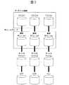
図3は本実施形態のホストコンピュータ上で認識されるデータベース領域と、オペレーティングシステムが認識する論理ボリュームと、デバイスファイル及びディスクサブシステム内のLUへのマッピング関連の例を示す図である。図3に示す様にデータベース管理処理部10では、データを格納するデータベース領域は、複数のファイルから構成されるものとして認識されている。構成する各ファイルは、ホストコンピュータ1上のオペレーティングシステムのファイルに対応しており、図3ではオペレーティングシステムにおいてRAWデバイスとして認識されるケースを想定している。更に、オペレーティングシステムのファイルは、物理的な磁気ディスク装置に対応するデバイスファイルとして管理されており、そのデバイスファイルは、前述した様にディスクサブシステム2内の各々の磁気ディスク装置に対応するLUにマッピングされている。
【0036】
次に図4から図7に示す流れ図を用いてホストコンピュータ1上のデータベース管理処理部10からログバッファ14中のログブロック262aのディスクサブシステム2への書き込みを要求するアクセス要求の処理について説明する。始めに、図4を用いて処理の概要を示す。
【0037】
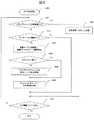
図4は本実施形態の受信コマンド解析処理の処理手順を示すフローチャートである。図4に示した処理は、ディスクサブシステム2内のプロセッサによって実行されるディスク制御処理部21の処理として実現されるものであり、ホストコンピュータ1からのアクセス要求を受領したディスクサブシステム2は、始めに受領コマンドの解析処理を行う(ステップ300)。接続チャネルのプロトコルに従ってコマンドを解析することで、アクセス要求がREADコマンドであるかWRITEコマンドであるかを識別できるものとする。
【0038】
ステップ320でディスク制御処理部21は、受領コマンドがWRITEコマンドであるかを判定し、WRITEコマンドである場合にはWRITEコマンド処理を行う(ステップ340)。また、READコマンドである場合にはREADコマンド処理(ステップ360)を行う。
【0039】
図5は本実施形態のWRITEコマンド受領時の処理手順を示すフローチャートである。図5の様に更新処理部30は、ディスク制御処理部21からコマンドを受領すると、受信コマンドからコマンド種類とアクセス先アドレスを解析し、WRITEコマンドであることを認識する(ステップ341)。ここで、アクセス先アドレスからは、複数のディスクサブシステムやその各磁気ディスク装置に割り当てられているアドレスを示す装置構成管理テーブルの情報との比較を行うことにより、アクセス要求先のディスク制御装置番号とドライブ番号を識別することができるものとする。
【0040】
次に、ステップ341で解析したアクセス先アドレスのデータが、ディスクサブシステム2のキャッシュメモリ22に保持されているかどうかを調べ、キャッシュヒットミス判定を行う(ステップ342)。
【0041】
アクセス先データがキャッシュメモリ22に保持されていないキャッシュミスの場合には、前記の様にアクセス要求先のドライブ番号を識別し、ディスクサブシステム2のディスクアクセス制御部23に対してそのドライブ番号に対応する磁気ディスク装置からキャッシュメモリ22ヘの転送依頼を行う(ステップ343)。この場合、転送終了までWRITE処理を中断し(ステップ344)、転送処理終了後、再度WRITE処理を継続する。また、転送先のキャッシュアドレスはキャッシュの空きリスト等、一般的な方法で管理、取得すれば良いが、転送先アドレスについては、キャッシュ管理テーブルを更新することで登録する必要がある。
【0042】
ステップ342でキャッシュヒットの判定の場合、またはステップ344で転送処理が終了した場合には、ディスクサブシステム2内のキャッシュメモリ22に対して当該データの更新を行う(ステップ345)。すなわち、ホストコンピュータ1から受領したデータの内容を書き込む。
【0043】
データの更新が終了した後、前記アクセス先アドレスがログ用ディスク26内のアドレスであるかどうかを調べて当該データがデータベース処理のログ用ディスク26のデータであるかを判定し(ステップ346)、書き込み内容がログ用ディスク26へのデータ、すなわちログブロックである場合には、そのログブロックの内容に従って該当するデータベース領域24のデータベースブロックヘのログ追跡処理を行う(ステップ347)。
【0044】
ログ追跡処理が完了するか、ステップ346の判定でログブロックではないと判定された場合、ホストコンピュータ1に対してWRITEコマンド処理の完了報告を行う(ステップ348)。
【0045】
図6は本実施形態のログ追跡処理の処理手順を示すフローチャートである。ログブロックは複数のログレコードの集まりである。従って、図6に示す様にログブロックに含まれるログレコードについて順次、処理を行っていく。
【0046】
まず更新処理部30は、ログレコードのログ情報がトランザクションの開始処理、COMMITまたはROLLBACKといった決着処理を示す情報であるかを判定する(ステップ401)。
【0047】
当該ログレコードがトランザクションの状態変更ログではない場合には、更にデータベースの更新履歴を示すトランザクション更新ログであるかを判定する(ステップ402)。
【0048】
当該ログレコードがトランザクション更新ログである場合には、図2に示したDB−ディスクブロック変換テーブル28を参照し、ログレコード中に記録されたログ情報に含まれているデータベース領域ID、ファイルID、ページ番号から、対応する物理ディスクのディスク制御装置番号とドライブ番号とページ番号を識別する(ステップ403)。すなわち、当該ログ情報に含まれているデータベース領域ID及びファイルIDに一致するレコードを、DB−ディスクブロック変換テーブル28から検索して該当するディスク制御装置番号、ドライブ番号及び相対位置を求めた後、その相対位置がファイルの先頭であるものとして、当該ログ情報のページ番号を物理ディスク上のページ番号に変換する。
【0049】
次にステップ403で前記の様に識別したデータがキャッシュメモリ22に保持されているかどうかを調べてキャッシュヒットミス判定を行う(ステップ404)。当該データがキャッシュメモリ22に保持されていないキャッシュミスの場合には、ディスクアクセス制御部23に対して当該データベースブロックのドライブからキャッシュメモリ22ヘの転送依頼を行う(ステップ405)。
【0050】
ステップ404で当該データベースブロックがキャッシュヒットするか、ステップ405で転送処理が終了するとキャッシュメモリ22中の当該データベースブロックに対してログレコードに含まれているデータベース更新履歴情報を反映する(ステップ406)。
【0051】
一方、ステップ401で判定した結果、当該ログレコードがトランザクションの状態変更ログであり、ROLLBACKログである場合には、ステップ408で当該トランザクションによる更新履歴情報の反映を取り消す処理を行う。
【0052】
ステップ407では、当該ログブロックの全ログレコードの処理を完了したかどうかを調べ、まだ全ログレコードの処理を完了していない場合にはステップ401へ戻り、完了した場合には処理を終了する。
【0053】
図7は本実施形態のREADコマンド受領時の処理手順を示すフローチャートである。図7の様に更新処理部30は、ディスク制御処理部21からコマンドを受領すると、受信コマンドからコマンドの種類とアクセス先アドレスを解析し、READアクセス要求であることを認識する(ステップ361)。ここで、アクセス先アドレスからは、前記と同様にして装置構成管理テーブルを参照することで、アクセス要求先のディスク制御装置番号とドライブ番号を識別できるものとする。
【0054】
次に、ステップ361で解析したアクセス先アドレスのデータが、ディスクサブシステム2のキャッシュメモリ22に保持されているかどうかを調べ、キャッシュヒットミス判定を行う(ステップ362)。
【0055】
アクセス先データがキャッシュメモリ22に保持されていないキャッシュミスの場合には、前記の様にアクセス要求先のドライブ番号を識別し、ディスクサブシステム2のディスクアクセス制御部23に対してそのドライブ番号に対応する磁気ディスク装置からキャッシュメモリ22ヘの転送依頼を行う(ステップ363)。この場合、転送終了までREAD処理を中断し(ステップ364)、転送処理終了後、再度READ処理を継続する。また、転送先のキャッシュアドレスはキャッシュの空きリスト等、一般的な方法で管理、取得すれば良いが、転送先アドレスについては、キャッシュ管理テーブルを更新することで登録する必要がある。
【0056】
ステップ362でキャッシュヒットの判定の場合、またはステップ364で転送処理が終了した場合、従来の単純なデータの読み出しの場合では当該ディスクサブシステム内のキャッシュメモリのデータをチャネルに転送するが、本実施形態では、更に当該データがデータベース管理処理部10からのデータベースブロックのREAD要求であるかを判定する(ステップ365)。当該データがデータベースブロックであるかは、DB−ディスクブロック変換テーブル28を参照し、該当ドライブ番号の存在を判定することによって識別できる。
【0057】
当該データがデータベースブロックである場合には、それ以前のWRITE要求で受信し、ログ追跡処理の終了していないログ情報中にそのデータベースブロックを更新するログレコードが含まれているかどうかを判定し、含まれている場合にはその更新を行う。
【0058】
すなわち、そのREADアクセス要求先の物理ドライブのドライブ番号とページ番号をアクセス先アドレスから求め、ログ追跡処理の終了していないログレコードの物理ドライブのドライブ番号及びページ番号と比較して、キャッシュメモリ22中のログブロック262a内のログレコード中に反映する必要のあるログレコードがあるかを判定し(ステップ366)、該当ログレコードが存在した場合にはログ追跡処理を行う(ステップ367)。
そして、ステップ365の処理によって該当データがデータベースブロックでないと判定された時点か、若しくはステップ367のログ追跡処理が完了した時点で該当データをチャネルに転送する。
【0059】
前記の様に本実施形態では、DBバッファ12に対する更新処理の内容を示すログ情報によりディスクサブシステム2上のデータベース領域24のデータを更新するので、従来のデータベース管理システムで行っていたデータベースブロックの記憶装置サブシステムへの書き込みについては本実施形態では必要無くなる。また、チェックポイント取得時にも同様にログ情報によりデータベース領域24への書き込みをディスクサブシステム2側で行う。この為、本実施形態においてホストコンピュータ1は、チェックポイント取得処理等のDBバッファ12の内容をディスクサブシステム2へ反映させる処理を瞬時に終了させることが可能であり、ログ情報によりディスクサブシステム2上でデータベース領域24のデータを更新している間も、ホストコンピュータ1側ではデータベース処理を続行することができる。
【0060】
この際、ホストコンピュータ1でデータベース処理を続行中にアクセス対象のデータがDBバッファ12中に存在していないことが検出され、ディスクサブシステム2に対してデータベースブロックの読み込み要求が行われた場合には、その読み込み対象のデータベースブロックをログ情報の内容に従って更新した後にホストコンピュータ1へ送信するので、ホストコンピュータ1は、ディスクサブシステム2でのログ追跡処理を何ら意識すること無くデータベース処理を続行することが可能である。
【0061】
更に本実施形態では、ホストコンピュータ1からディスクサブシステム2へのデータベースブロックの書き込みが不要になることによって、ディスクサブシステム2に対する帯域幅を大幅に増加させたのと同様の効果を得ることが可能になる。すなわち本実施形態では、DBバッファ12の内容をディスクサブシステム2内のデータベース領域24に反映させる必要が生じた場合に、更新処理の行われたレコードを1つでも含むデータベースブロック242a全てをディスクサブシステム2へ送信するのではなく、DBバッファ12に対する更新処理の内容を示すログブロック262aをディスクサブシステム2へ送信するので、ディスクサブシステム2へ送信されるデータ量を減少させることが可能であり、この為、ディスクサブシステム2に対する帯域幅を相対的に増加させることができる。
【0062】
一方、ホストコンピュータ1側のデータベース管理処理が障害によってダウンした場合であっても、ディスクサブシステム2上のキャッシュメモリ22は、最新のデータベースブロック242の状態が保持されたウォームキャッシュ状態となっているので、再開始処理時にホストコンピュータ1からディスクサブシステム2に対する入出力要求があった場合にキャッシュヒットとなり、実際に磁気ディスク装置上のデータベース領域24までアクセスする頻度を極端に軽減することができる。
【0063】
以上説明した様に本実施形態のデータベース処理システムによれば、ホストコンピュータのバッファ上で行われたデータベース処理の内容を示すログ情報に従って記憶装置サブシステム上のデータベース領域のデータを更新するので、ホストコンピュータのバッファ上で行われたデータベース処理の内容を記憶装置サブシステム上のデータベース領域へ反映させる際に、ホストコンピュータと記憶装置サブシステムとの間の入出力処理負荷を低減させることが可能である。
【0064】
データベース領域へ反映したデータは、記憶装置サブシステム内のキャッシュに格納されているため、反映データを利用する場合や、特にデータを大量に参照するホストコンピュータの障害回復処理の高速化を図ることが可能である。
【0065】
(実施形態2)
以下にログ情報の内、COMMITされたトランザクションのログ情報を用いて更新を行う実施形態2のデータベース処理システムについて説明する。
実施形態1のログ追跡処理では、全てのログレコードを対象に該当するデータベースブロックヘの反映処理を行ったが、本実施形態ではログ追跡処理の別の実施方法について図8から図10を用いて説明する。
【0066】
図8は本実施形態のログ追跡処理においてログブロック中に含まれる全てのログレコードについてトランザクション毎にログを解析した結果の例を示す図である。図8に示す様に本実施形態では、ログブロック262aを解析し、まず当該ディスクサブシステム内のキャッシュメモリ22とは異なる共用メモリ上に抽出ログバッファ264を確保して、抽出ログバッファ264に全てのログレコード266a〜266lを格納する。
【0067】
このとき、各ログレコードをトランザクション別に管理する為、トランザクションログ管理テーブル268によって各々のログレコードをトランザクション別に管理し、トランザクションTR1からトランザクションTR4までのログレコードのチェインをそれぞれ生成する。
【0068】
すなわち、トランザクションTR1には、トランザクションログ管理テーブル268a、268b、268c、乃至268fがチェインされ、トランザクションTR2には、トランザクションログ管理テーブル268e、268gがチェインされる。またトランザクションTR3には、トランザクションログ管理テーブル268h、268j、268lがチェインされ、トランザクションTR4には、トランザクションログ管理テーブル268i、268kがチェインされる。
【0069】
この様に、トランザクションログ管理テーブル268を各々のトランザクション毎にチェインさせることにより、ログレコード情報にトランザクションの正常決着処理を示すCOMMITが識別されたトランザクションのログレコードだけを対象にすることができる。
【0070】
図9は本実施形態の図8のトランザクションログ管理テーブル268を用いる際のログレコード分別処理の処理手順を示すフローチャートである。本処理は、図5のステップ347で示したWRITEコマンド処理に代わる処理である。
【0071】
ログブロック中の各ログレコードについて、トランザクション開始を示すトランザクションBEGINログであるかを判定し(ステップ441)、トランザクションBEGINログである場合、そのログを抽出ログバッファ264へ追加し、トランザクションログ管理テーブル268ヘの登録を行う。
【0072】
ステップ441の判定でトランザクションBEGINログではないと判定された場合にはデータベース更新ログであるかを判定し(ステップ443)、データベース更新ログである場合には、該当するトランザクション識別子と同じトランザクションログ管理テーブル268の最後尾にチェインする。
【0073】
ステップ443の判定でトランザクション更新ログではないと判定された場合には、トランザクションの無効化を示すトランザクションROLLBACKログかであるかを判定し(ステップ445)、トランザクションROLLBACK処理である場合には、該当するトランザクション識別子と同じ識別子のトランザクションログ管理テーブル268を削除すると同時に抽出ログバッファ264の該当するログレコードも削除する。すなわち、ROLLBACKしたトランザクションのログは、データベースブロックヘ反映されない様にする。
【0074】
ステップ445の判定でトランザクションROLLBACKログではないと判定された場合には、トランザクションの有効化を示すトランザクションCOMMITログであるかを判定し(ステップ447)、トランザクションCOMMITログである場合にはログ追跡処理を行う(ステップ448)。
【0075】
ステップ447の判定でトランザクションCOMMITログではないと判定された後、ステップ449でログブロックの終了を検出するまでステップ441からステップ449までを繰り返す。
【0076】
図10は本実施形態の図9のステップ448におけるログ追跡処理の処理手順を示すフローチャートである。図10のログ追跡処理では、COMMITしたトランザクションのトランザクションログ管理テーブル268の先頭アドレスの次のアドレスが引き渡される。つまり、トランザクションBEGINログを処理の対象から外すことができる。
【0077】
この処理では、1つのトランザクションの複数のログレコードの集まりについて順次、処理を行っていく。まずステップ4481では、ログレコードのログ情報がトランザクションのCOMMITログであるかどうかを判定し、当該ログレコードが、COMMITログではなく、トランザクション更新ログである場合には、ログレコード中に記録された当該ログ情報に含まれているデータベース領域ID、ファイルID及びページ番号と、図2に示したDB−ディスクブロック変換テーブル28の情報とを比較し、対応する物理ディスクのディスク制御装置番号とドライブ番号とページ番号を識別する(ステップ4482)。
【0078】
次にステップ4481で識別した当該データについてキャッシュメモリ22に対してキャッシュヒットミス判定を行う(ステップ4483)。当該データがキャッシュメモリに保持されていないキャッシュミスの場合には、ディスクアクセス制御部23に対して当該データベースブロックのドライブからキャッシュメモリ22ヘの転送依頼を行う(ステップ4484)。
【0079】
ステップ4483で当該データベースブロックがキャッシュヒットするか、ステップ4484で転送処理が終了すると、キャッシュメモリ22中の当該データベースブロックに、ログレコードに含まれるデータベース更新履歴情報を反映する(ステップ4485)。
ステップ4481からステップ4485までの処理を、当該トランザクションの全ログレコードの処理が完了するまで行う(ステップ4486)。
【0080】
一方、ステップ4481の判定でトランザクションCOMMITログが出現した場合には、当該トランザクションのログについて全て処理を反映し終わっているのでステップ4487へ進み、トランザクションログ管理テーブル268及びトランザクション抽出ログバッファ264から当該トランザクションに関する全ての情報を削除する。
【0081】
以上説明した様に本実施形態のデータベース処理システムによれば、ログ情報の内、COMMITされたトランザクションのログ情報を用いて更新を行うので、ホストコンピュータのバッファ上で行われたデータベース処理の内容をログ情報によって記憶装置サブシステム上のデータベース領域へ反映させる際の入出力処理を省略することが可能である。
【0082】
(実施形態3)
以下にデータベース領域のデータの更新を、そのデータベース領域のデータに対応する物理デバイス毎に並列に行う実施形態3のデータベース処理システムについて説明する。
【0083】
図11は本実施形態のデータベース処理システムの概略構成を示す図である。本実施形態の処理は、実施形態1及び実施形態2に共通して実施することができる。すなわち、実施形態1の図6におけるログ追跡処理及び実施形態2の図10におけるログ追跡処理において、データベースブロックのデータベース領域ID、ファイルID及びページ番号から、DB−ディスクブロック変換テーブル28を使用して物理ドライブのドライブ番号を取得した後、ドライブ毎に異なるプロセッサに処理を分割して実行することで、キャッシュメモリ22ヘの書き込み処理を並列化する。つまり、キャッシュメモリに書き込むことで、各ドライブへの反映処理を並列処理させることができ、高速なデータ反映が可能となる。ここで本実施形態のディスクサブシステムは、ドライブ毎の処理を実行する複数のプロセッサを備えているものとする。
【0084】
以上説明した様に本実施形態のデータベース処理システムによれば、ログ情報によるデータベース領域のデータの更新を、そのデータベース領域のデータに対応する物理デバイス毎に並列に行うので、ホストコンピュータのバッファ上で行われたデータベース処理の内容をログ情報によって記憶装置サブシステム上のデータベース領域へ反映させる際に、その処理を効率的に行うことが可能である。
【0085】
(実施形態4)
以下にディスクサブシステムを追加した場合の実施形態4のデータベース処理システムについて説明する。
図12は本実施形態のデータベース処理システムの概略構成を示す図である。図12に示す様に本実施形態のディスクサブシステム1200はデータ送信処理部31を有している。データ送信処理部31は、ログ情報の内容に従って更新されるデータベース領域のデータがディスクサブシステム1200とは異なるディスクサブシステム1201中に存在している場合に、そのログ情報の内容をディスクサブシステム1201へ送信する処理部である。
【0086】
ディスクサブシステム1200をデータ送信処理部31として機能させる為のプログラムは、フロッピーディスク等の記録媒体に記録されて実行されるものとする。なお前記プログラムを記録する記録媒体はフロッピーディスク以外の他の記録媒体でも良い。また前記プログラムを当該記録媒体から情報処理装置にインストールして使用しても良いし、ネットワークを通じて当該記録媒体にアクセスして前記プログラムを使用するものとしても良い。
【0087】
またディスクサブシステム1201はデータ受信処理部32を有している。データ受信処理部32は、前記送信されたログ情報を受信して、ディスクサブシステム1201の更新処理部30へ、ディスクサブシステム1201内のデータベース領域24のデータの更新を指示する処理部である。
【0088】
ディスクサブシステム1201をデータ受信処理部32として機能させる為のプログラムは、フロッピーディスク等の記録媒体に記録されて実行されるものとする。なお前記プログラムを記録する記録媒体はフロッピーディスク以外の他の記録媒体でも良い。また前記プログラムを当該記録媒体から情報処理装置にインストールして使用しても良いし、ネットワークを通じて当該記録媒体にアクセスして前記プログラムを使用するものとしても良い。
【0089】
次に本実施形態について図12を用いて説明する。本実施形態では、実施形態1で示した構成にもう1つのディスクサブシステムを追加した場合の例を表している。つまり、追加したディスクサブシステム1201にはデータベース領域だけが存在する例を示している。
【0090】
本実施形態では、データベース管理処理部10が管理するデータベース領域24がディスクサブシステム1200及び1201に存在している。但し、ログ領域はディスクサブシステム1200にしか存在していない。この様な場合、ディスクサブシステム1200のディスク制御処理部21には、ホストコンピュータ1からWRITE要求のあったログブロックを判定し、ディスクサブシステム1201にログブロックを送信するデータ送信処理部31が必要になる。また、ディスクサブシステム1201にはデータ送信処理部31から送信されたデータを受信するデータ受信処理部32が必要となる。
【0091】
複数台のディスクサブシステムを用いて大規模なデータベースシステムを構築した場合、この様なデータベース領域が配置される場合があるが、本実施形態では、以下の様に処理を行う。
すなわち、ディスクサブシステム1200のデータ送信処理部31は、 ログ情報の内容に従って更新されるデータベース領域のデータについて、そのディスク制御装置番号を図2のDB−ディスクブロック変換テーブル28から求め、その求めたディスク制御装置番号がディスクサブシステム1200の番号と異なっている場合には、そのディスク制御装置番号のディスクサブシステム、例えばディスクサブシステム1201のデータ受信処理部32へ送信し、データ受信処理部32により、そのログ情報を受信して、ディスクサブシステム1201の更新処理部30へ、ディスクサブシステム1201内のデータベース領域24のデータの更新を指示する。
【0092】
以上説明した様に本実施形態のデータベース処理システムによれば、ログ情報の内容に従って更新されるデータベース領域のデータが他の記憶装置サブシステム中に存在している場合に、そのログ情報の内容を当該記憶装置サブシステムへ送信し、その記憶装置サブシステム内でデータベース領域のデータの更新を行うので、複数台の記憶装置サブシステムにデータベース領域を配置している大規模なデータベース処理システムで、ホストコンピュータのバッファ上で行われたデータベース処理の内容を記憶装置サブシステム上のデータベース領域へ反映させる際にも、ホストコンピュータと記憶装置サブシステムとの間の入出力処理負荷を低減させることが可能である。また、反映したデータを利用する場合も複数の記憶装置サブシステム内のキャッシュメモリに格納されているため、並列に参照することができ、高速にアクセスすることが可能である。
【0093】
【発明の効果】
本発明によればホストコンピュータで行われたデータベース処理の内容を示すログ情報に従って記憶装置サブシステム上のデータベース領域のデータを更新するので、ホストコンピュータで行われたデータベース処理の内容を記憶装置サブシステム上のデータベース領域へ反映させる際に、ホストコンピュータと記憶装置サブシステムとの間の入出力処理負荷を低減させることが可能である。
【図面の簡単な説明】
【図1】実施形態1のデータベース処理システムのシステム構成を示す図である。
【図2】実施形態1のDB−ディスクブロック変換テーブル28の構成情報を示す図である。
【図3】実施形態1のホストコンピュータ上で認識されるデータベース領域と、オペレーティングシステムが認識する論理ボリュームと、デバイスファイル及びディスクサブシステム内のLUへのマッピング関連の例を示す図である。
【図4】実施形態1の受信コマンド解析処理の処理手順を示すフローチャートである。
【図5】実施形態1のWRITEコマンド受領時の処理手順を示すフローチャートである。
【図6】実施形態1のログ追跡処理の処理手順を示すフローチャートである。
【図7】実施形態1のREADコマンド受領時の処理手順を示すフローチャートである。
【図8】実施形態2のログ追跡処理においてログブロック中に含まれる全てのログレコードについてトランザクション毎にログを解析した結果の例を示す図である。
【図9】実施形態2の図8のトランザクションログ管理テーブル268を用いる際のログレコード分別処理の処理手順を示すフローチャートである。
【図10】実施形態2の図9のステップ448におけるログ追跡処理の処理手順を示すフローチャートである。
【図11】実施形態3のデータベース処理システムの概略構成を示す図である。
【図12】実施形態4のデータベース処理システムの概略構成を示す図である。
【符号の説明】
1…ホストコンピュータ、2…ディスクサブシステム、12…DBバッファ、14…ログバッファ、16…ストレージエリアネットワーク、22…キャッシュメモリ、24…データベース領域、242…データベースブロック、26…ログ用ディスク、262…ログブロック、28…DB−ディスクブロック変換テーブル、10…データベース管理処理部、21…ディスク制御処理部、23…ディスクアクセス制御部、30…更新処理部、264…抽出ログバッファ、266…ログレコード、268…トランザクションログ管理テーブル、1200及び1201…ディスクサブシステム、31…データ送信処理部、32…データ受信処理部。[0001]
BACKGROUND OF THE INVENTION
The present invention relates to a database processing system that performs database processing by connecting a host computer and a storage device subsystem, and in particular, the database processing contents are stored in a database in the storage device subsystem by log information indicating the contents of the database processing of the host computer. The present invention relates to a technique effective when applied to a database processing system to be reflected.
[0002]
[Prior art]
In a conventional database management system, database blocks and log blocks are input and output between a host computer and a storage device subsystem. That is, in order for the database management system to improve input / output efficiency, a database buffer is set on the main memory of the host computer, and a storage device (a low-speed, large-capacity magnetic disk device compared to the main memory) is set on the buffer. The input / output from the storage device is reduced as much as possible by caching the database block input from the storage device.
[0003]
In such a database management system, data update processing is performed on a database block previously input on the database buffer, the update history information at that time is written as a log in a log dedicated buffer, and then the transaction is settled. Consistency is sometimes guaranteed by forcibly outputting the log to a storage device. At this time, in reflecting (writing) the database block in the storage device, it is necessary to comply with a so-called WAL (Write Ahead Log) in which an update history log performed on the block is output to the storage device in advance.
[0004]
In addition, the database management system acquires checkpoints during operation in order to guarantee the consistency of the DB periodically in preparation for a failure. The check point is a point where the consistency of the database that is the starting point for performing the restart process in the event of a system failure is guaranteed. Checkpoints are often acquired when the number of log blocks output during operation reaches a certain number. In the checkpoint process, a process of writing all the database blocks that have been updated on the database buffer at that time onto the storage device is performed (see, for example, Non-Patent Document 1).
[0005]
[Non-Patent Document 1]
Jim Gray, Andreas Reuter, "Transaction Processing: CONCEPTS AND TECHNIQUES" (USA), 1st edition, Morgan Kaufman Publisher ( Published by MORGAN KAUFMAN PUBLISHERS), 1993, pp.556-557, pp.604-609
[0006]
[Problems to be solved by the invention]
In the conventional method for writing database blocks to the storage device in the database management system, the process of writing all the database blocks updated on the database buffer onto the storage device as described above is performed. Since the database block contains records that have not been updated, unnecessary input / output occurs, and the input / output processing between the host computer and the storage subsystem is heavily loaded. is there.
[0007]
The object of the present invention is to solve the above-mentioned problem, and to reflect the contents of the database processing performed on the buffer of the host computer to the database area on the storage device subsystem, between the host computer and the storage device subsystem. An object of the present invention is to provide a technique capable of reducing the input / output processing load.
[0008]
Another object of the present invention is to provide a technique capable of executing the recovery process at a high speed because the reflected data of the database is stored in the cache memory of the storage subsystem during the failure recovery process of the host computer. There is to do.
[0009]
Another object of the present invention is that unnecessary input / output processing can be omitted when the contents of database processing performed on the buffer of the host computer are reflected in the database area on the storage subsystem by log information. To provide technology.
[0010]
Another object of the present invention is a technique capable of efficiently performing the processing when reflecting the contents of the database processing performed on the buffer of the host computer to the database area on the storage subsystem by the log information. Is to provide.
[0011]
Another object of the present invention is a large-scale database processing system in which database areas are arranged in a plurality of storage device subsystems, and the contents of database processing performed on the buffer of the host computer are stored on the storage device subsystem. It is another object of the present invention to provide a technique capable of reducing an input / output processing load between a host computer and a storage device subsystem even when reflecting in a database area.
[0012]
[Means for Solving the Problems]
The present invention relates to a database processing system that performs processing for reflecting the contents of database processing performed on a buffer of a host computer to a database on a storage device, and stores the processing according to log information indicating the contents of database processing performed on the host computer. The database processing contents are reflected in the data in the database area on the device subsystem.
[0013]
In the database processing system of the present invention, the host computer includes a database buffer that temporarily holds the contents of the database area in the storage device subsystem, and a log buffer that temporarily holds the contents of the update process for the database buffer. If the contents of the database buffer are changed as the database processing is executed on the host computer, and the change needs to be reflected in the database area in the storage subsystem, it is performed on the database buffer. An access request for requesting writing of log information indicating the contents of the update processing to the storage device subsystem is transmitted from the host computer to the storage device subsystem.
[0014]
The storage subsystem receives the access request from the host computer and determines whether the received access request is a write request or a read request. If the received access request is a write request, it is determined whether or not the written content is log information indicating the content of database processing performed by the host computer.
[0015]
As a result of the determination, if the written content is the log information, the correspondence between the logical position information recognized by the database processing on the host computer side and the physical position information on the storage subsystem After converting the position information indicated in the log information into physical position information on the storage device subsystem, the storage device sub indicated by the converted physical position information is referred to Data in the database area on the system is updated according to the contents of the log information.
[0016]
At that time, when the reflection target data is stored in the cache memory of the storage device subsystem, the reflection target data stored in the cache memory is reflected. If it is not stored in the cache memory, the reflection target data is uploaded to the cache memory, and then the reflection target data is stored in the cache memory.
[0017]
Further, when there is no data to be accessed in the database processing in the database buffer, the host computer transmits a request to read the data from the host computer to the storage device subsystem. If the access request received from the host computer is a read request, it is determined whether the log information received by the previous write request contains log information that updates the data to be read. If the information includes log information for updating the data to be read, the data to be read is updated according to the contents of the log information and transmitted to the host computer side.
[0018]
As described above, in the present invention, when it is necessary to reflect the contents of the database buffer in the database area in the storage subsystem, all the database blocks including at least one record that has been updated are transferred from the host computer. Data transmitted between the host computer and the storage device subsystem is transmitted from the host computer to the storage device subsystem instead of being transmitted to the storage device subsystem. The amount can be reduced.
[0019]
As described above, according to the database processing system of the present invention, the data in the database area on the storage device subsystem is updated according to the log information indicating the contents of the database processing performed on the buffer of the host computer. When reflecting the contents of the database processing performed on the buffer to the database area on the storage device subsystem, it is possible to reduce the input / output processing load between the host computer and the storage device subsystem.
[0020]
DETAILED DESCRIPTION OF THE INVENTION
(Embodiment 1)
The database processing system according to the first embodiment that performs processing for reflecting the contents of database processing performed on the buffer of the host computer to the database on the magnetic disk device of the disk subsystem will be described below.
[0021]
FIG. 1 is a diagram showing a system configuration of a database processing system according to the present embodiment. As shown in FIG. 1, the
[0022]
A program for causing the
The
[0023]
The disk
[0024]
The disk
[0025]
It is assumed that a program for causing the
[0026]
The
In the
[0027]
In the
[0028]
In this embodiment, log information, which is update history information of data updated by a transaction operating in the database
[0029]
When the data is written, the
[0030]
In other words, the
[0031]
The
[0032]
FIG. 2 is a diagram showing the configuration information of the DB-disk block conversion table 28 of this embodiment. As shown in FIG. 2, the DB-disk block conversion table 28 includes a database area ID, which is information for identifying the
[0033]
Files constituting the
[0034]
In the
[0035]
FIG. 3 is a diagram showing an example of the database area recognized on the host computer of this embodiment, the logical volume recognized by the operating system, and the mapping relation to the LU in the device file and disk subsystem. As shown in FIG. 3, the database
[0036]
Next, processing of an access request for requesting writing of the
[0037]
FIG. 4 is a flowchart showing the processing procedure of the received command analysis processing of this embodiment. The process shown in FIG. 4 is realized as a process of the disk
[0038]
In
[0039]
FIG. 5 is a flowchart showing a processing procedure when a WRITE command is received according to this embodiment. As shown in FIG. 5, when receiving the command from the disk
[0040]
Next, it is checked whether or not the data of the access destination address analyzed in
[0041]
In the case of a cache miss in which the access destination data is not held in the cache memory 22, the drive number of the access request destination is identified as described above, and the drive number is assigned to the disk
[0042]
If the cache hit is determined in
[0043]
After the data update is completed, it is checked whether the access destination address is an address in the
[0044]
If the log tracking process is completed or if it is determined in
[0045]
FIG. 6 is a flowchart showing the processing procedure of the log tracking processing of this embodiment. A log block is a collection of a plurality of log records. Therefore, as shown in FIG. 6, the log records included in the log block are sequentially processed.
[0046]
First, the
[0047]
If the log record is not a transaction state change log, it is further determined whether the log record is a transaction update log indicating a database update history (step 402).
[0048]
If the log record is a transaction update log, the DB-disk block conversion table 28 shown in FIG. 2 is referred to, and the database area ID, file ID, and log ID included in the log information recorded in the log record The disk controller number, drive number, and page number of the corresponding physical disk are identified from the page number (step 403). That is, after searching the DB-disk block conversion table 28 for a record that matches the database area ID and file ID included in the log information and obtaining the corresponding disk controller number, drive number, and relative position, Assuming that the relative position is the beginning of the file, the page number of the log information is converted into the page number on the physical disk.
[0049]
Next, it is checked whether or not the data identified as described above in
[0050]
When the database block hits in
[0051]
On the other hand, as a result of the determination in
[0052]
In
[0053]
FIG. 7 is a flowchart showing a processing procedure when a READ command is received according to this embodiment. As shown in FIG. 7, when the
[0054]
Next, it is checked whether or not the data of the access destination address analyzed in
[0055]
In the case of a cache miss in which the access destination data is not held in the cache memory 22, the drive number of the access request destination is identified as described above, and the drive number is assigned to the disk
[0056]
When the cache hit is determined at
[0057]
If the data is a database block, determine whether or not a log record for updating the database block is included in the log information that has been received in the previous WRITE request and the log tracking process has not ended, If it is included, update it.
[0058]
That is, the drive number and page number of the physical drive of the READ access request destination are obtained from the access destination address, and compared with the drive number and page number of the physical drive of the log record for which log tracking processing has not been completed. It is determined whether there is a log record that needs to be reflected in the log records in the
Then, when it is determined that the corresponding data is not a database block by the process of
[0059]
As described above, in this embodiment, the data in the
[0060]
At this time, when it is detected that the access target data does not exist in the
[0061]
Furthermore, in the present embodiment, it is possible to obtain the same effect as that of greatly increasing the bandwidth for the
[0062]
On the other hand, even when the database management process on the
[0063]
As described above, according to the database processing system of the present embodiment, the data in the database area on the storage device subsystem is updated according to the log information indicating the contents of the database processing performed on the buffer of the host computer. It is possible to reduce the input / output processing load between the host computer and the storage subsystem when reflecting the contents of the database processing performed on the computer buffer to the database area on the storage subsystem. .
[0064]
Since the data reflected in the database area is stored in the cache in the storage device subsystem, it is possible to speed up the failure recovery processing of the host computer that uses the reflected data or particularly a host computer that references a large amount of data. Is possible.
[0065]
(Embodiment 2)
A database processing system according to the second embodiment that performs update using log information of a COMMIT transaction among log information will be described below.
In the log tracking process of the first embodiment, all log records are reflected in the corresponding database block. In this embodiment, another method for executing the log tracking process is described with reference to FIGS. explain.
[0066]
FIG. 8 is a diagram illustrating an example of a result of analyzing a log for each transaction for all log records included in a log block in the log tracking process of the present embodiment. As shown in FIG. 8, in this embodiment, the
[0067]
At this time, in order to manage each log record for each transaction, each log record is managed for each transaction by the transaction log management table 268, and a chain of log records from transaction TR1 to transaction TR4 is generated.
[0068]
That is, transaction log management tables 268a, 268b, 268c to 268f are chained to transaction TR1, and transaction log management tables 268e and 268g are chained to transaction TR2. Transaction TR3 is chained with transaction log management tables 268h, 268j, 268l, and transaction TR4 is chained with transaction log management tables 268i, 268k.
[0069]
As described above, by chaining the transaction log management table 268 for each transaction, it is possible to target only the log record of the transaction in which the COMMIT indicating the normal completion processing of the transaction is identified in the log record information.
[0070]
FIG. 9 is a flowchart showing a processing procedure of log record sorting processing when the transaction log management table 268 of FIG. 8 of this embodiment is used. This process is an alternative to the WRITE command process shown at
[0071]
For each log record in the log block, it is determined whether it is a transaction BEGIN log indicating transaction start (step 441). If it is a transaction BEGIN log, the log is added to the
[0072]
If it is determined in
[0073]
If it is determined in
[0074]
If it is determined in
[0075]
After it is determined in
[0076]
FIG. 10 is a flowchart showing the processing procedure of the log tracking process in
[0077]
In this processing, processing is sequentially performed on a collection of a plurality of log records of one transaction. First, in step 4481, it is determined whether the log information of the log record is a transaction COMMIT log. If the log record is not a COMMIT log but a transaction update log, the log record is recorded in the log record. The database area ID, file ID, and page number included in the log information are compared with the information in the DB-disk block conversion table 28 shown in FIG. 2, and the disk controller number and drive number of the corresponding physical disk are compared. The page number is identified (step 4482).
[0078]
Next, a cache hit / miss determination is performed on the cache memory 22 for the data identified at step 4481 (step 4483). In the case of a cache miss in which the data is not held in the cache memory, the disk
[0079]
When the database block hits the cache in
The processing from step 4481 to step 4485 is performed until processing of all log records of the transaction is completed (step 4486).
[0080]
On the other hand, if a transaction COMMIT log appears in the determination in step 4481, since all processing has been reflected for the log of the transaction, the process proceeds to step 4487, and the transaction is retrieved from the transaction log management table 268 and the transaction
[0081]
As described above, according to the database processing system of the present embodiment, update is performed using the log information of the COMMIT transaction, so that the contents of the database processing performed on the buffer of the host computer are changed. It is possible to omit the input / output processing when reflecting the log information in the database area on the storage subsystem.
[0082]
(Embodiment 3)
A database processing system according to the third embodiment that updates data in the database area in parallel for each physical device corresponding to the data in the database area will be described below.
[0083]
FIG. 11 is a diagram showing a schematic configuration of the database processing system of the present embodiment. The processing of the present embodiment can be performed in common with the first and second embodiments. That is, in the log tracking process in FIG. 6 of the first embodiment and the log tracking process in FIG. 10 of the second embodiment, the DB-disk block conversion table 28 is used from the database area ID, file ID, and page number of the database block. After acquiring the drive number of the physical drive, the processing is divided into different processors for each drive and executed, thereby parallelizing the write processing to the cache memory 22. That is, by writing to the cache memory, reflection processing to each drive can be performed in parallel, and high-speed data reflection is possible. Here, it is assumed that the disk subsystem of this embodiment includes a plurality of processors that execute processing for each drive.
[0084]
As described above, according to the database processing system of this embodiment, the data in the database area is updated by the log information in parallel for each physical device corresponding to the data in the database area. When the contents of the database processing performed are reflected in the database area on the storage subsystem by log information, the processing can be performed efficiently.
[0085]
(Embodiment 4)
A database processing system according to the fourth embodiment when a disk subsystem is added will be described below.
FIG. 12 is a diagram showing a schematic configuration of the database processing system of the present embodiment. As shown in FIG. 12, the
[0086]
It is assumed that a program for causing the
[0087]
The
[0088]
It is assumed that a program for causing the
[0089]
Next, the present embodiment will be described with reference to FIG. In this embodiment, an example in which another disk subsystem is added to the configuration shown in the first embodiment is shown. That is, an example in which only the database area exists in the added
[0090]
In this embodiment, the
[0091]
When a large-scale database system is constructed using a plurality of disk subsystems, such a database area may be arranged. In this embodiment, processing is performed as follows.
That is, the data transmission processing unit 31 of the
[0092]
As described above, according to the database processing system of the present embodiment, when the data in the database area that is updated according to the content of the log information exists in another storage device subsystem, the content of the log information is changed. Since it is transmitted to the storage subsystem and the data in the database area is updated in the storage subsystem, the host is a large-scale database processing system in which the database areas are arranged in a plurality of storage subsystems. It is also possible to reduce the input / output processing load between the host computer and the storage device subsystem when reflecting the contents of the database processing performed on the computer buffer to the database area on the storage device subsystem. is there. Also, when the reflected data is used, it is stored in the cache memory in the plurality of storage device subsystems, so that it can be referred to in parallel and can be accessed at high speed.
[0093]
【The invention's effect】
According to the present invention, the data in the database area on the storage device subsystem is updated according to the log information indicating the content of the database processing performed by the host computer, so the content of the database processing performed by the host computer is stored in the storage device subsystem. When reflecting the above database area, it is possible to reduce the input / output processing load between the host computer and the storage subsystem.
[Brief description of the drawings]
FIG. 1 is a diagram showing a system configuration of a database processing system according to a first embodiment.
FIG. 2 is a diagram showing configuration information of a DB-disk block conversion table 28 according to the first embodiment.
FIG. 3 is a diagram illustrating an example of a database area recognized on the host computer of the first embodiment, a logical volume recognized by the operating system, and mapping related to device files and LUs in the disk subsystem.
FIG. 4 is a flowchart illustrating a processing procedure of received command analysis processing according to the first embodiment.
FIG. 5 is a flowchart illustrating a processing procedure when a WRITE command is received according to the first exemplary embodiment.
FIG. 6 is a flowchart illustrating a processing procedure of log tracking processing according to the first exemplary embodiment.
FIG. 7 is a flowchart illustrating a processing procedure when a READ command is received according to the first exemplary embodiment.
FIG. 8 is a diagram illustrating an example of a result of analyzing a log for each transaction for all log records included in a log block in the log tracking process according to the second embodiment.
9 is a flowchart showing a processing procedure of log record sorting processing when using the transaction log management table 268 of FIG. 8 of
10 is a flowchart showing a processing procedure of log tracking processing in
FIG. 11 is a diagram illustrating a schematic configuration of a database processing system according to a third embodiment.
FIG. 12 is a diagram showing a schematic configuration of a database processing system according to a fourth embodiment.
[Explanation of symbols]
DESCRIPTION OF
Claims (10)
Translated fromJapanese記憶装置サブシステムが、ホストコンピュータから送信されたアクセス要求を受信し、その受信したアクセス要求が書き込み要求または読み込み要求のいずれであるかを判定するステップと、前記受信したアクセス要求が書き込み要求である場合に、前記記憶装置サブシステムが、その書き込み内容がホストコンピュータのバッファ上で行われたデータベース処理の内容を示すログ情報であるかどうかを判定するステップと、前記書き込み内容が前記ログ情報である場合に、前記記憶装置サブシステムが、前記ログ情報中に格納された前記書き込み内容の位置を示すホストコンピュータ側のデータベース処理で認識しているデータベース領域ID、ファイルIDと記憶装置サブシステム上の物理的な位置に対応するディスク制御装置番号、物理ディスクIDとの対応関係を示す変換テーブルによって、前記ログ情報中に示された位置情報を記憶装置サブシステム上の物理的な位置情報に変換するステップと、前記記憶装置サブシステムが、その変換した物理的な位置情報で表される記憶装置サブシステム上のデータベース領域のデータを前記ログ情報の内容に従って更新するステップとを有することを特徴とするデータベース処理方法。In a database processing method for performing processing for reflecting the contents of database processing performed on a buffer of a host computer to a database on a storage device,
The storage subsystem receives the access request transmitted fromthe host computer, determines whether the received access request is a write request or a read request, and the received access request is a write request Thestorage subsystem determines whether the written content is log information indicating the content of database processing performed on a buffer of the host computer, and the written content is the log information. case,the storage device subsystem, the log indicating a position of the writing contents stored in the information database area ID which is recognized by the database processing of the host computer side, the physical on the file ID and the storage device subsystem Disk controller number and object corresponding to specific location By the conversion table showing the correspondence between the disk ID, the step of converting the positional information indicated in the log information to the physical location information on the storage subsystem,the storage device subsystem and its transformation Updating the data in the database area on the storage subsystem represented by physical location information according to the contents of the log information.
ホストコンピュータのデータベースバッファの内容を記憶装置サブシステム内の記憶装置へ反映させる必要が生じた場合に、そのデータベースバッファに対して行われたデータベース処理の内容を示すログ情報の書き込み要求をホストコンピュータから記憶装置サブシステムへ送信するステップと、データベースバッファ中にデータベース処理でアクセス対象となっているデータが存在していない場合に当該データの読み込み要求をホストコンピュータから記憶装置サブシステムへ送信するステップと、
前記記憶装置サブシステムが、ホストコンピュータから送信されたアクセス要求を受信し、その受信したアクセス要求が書き込み要求または読み込み要求のいずれであるかを判定するステップと、前記受信したアクセス要求が書き込み要求である場合に、前記記憶装置サブシステムが、その書き込み内容が前記ログ情報であるかどうかを判定するステップと、前記書き込み内容が前記ログ情報である場合に、前記記憶装置サブシステムが、前記ログ情報中に格納された前記書き込み内容の位置を示すホストコンピュータ側のデータベース処理で認識しているデータベース領域ID、ファイルIDと記憶装置サブシステム上の物理的な位置に対応するディスク制御装置番号、物理ディスクIDとの対応関係を示す変換テーブルによって、前記ログ情報中に示された位置情報を記憶装置サブシステム上の物理的な位置情報に変換するステップと、前記記憶装置サブシステムが、その変換した物理的な位置情報で表される記憶装置サブシステム上のデータベース領域のデータを前記ログ情報の内容に従って更新するステップとを有することを特徴とするデータベース処理方法。In a database processing method for performing processing for reflecting the contents of database processing performed on a buffer of a host computer to a database on a storage device,
When it is necessary to reflect the contents of the database buffer of the host computer to the storage device in the storage subsystem, a request for writing log information indicating the contents of the database processing performed on the database buffer is sent from the host computer. A step of transmitting to the storage device subsystem; a step of transmitting a data read request from the host computer to the storage device subsystem when there is no data to be accessed in the database processing in the database buffer;
The storage subsystem receives an access request transmitted froma host computer, determines whether the received access request is a write request or a read request, and the received access request is a write request. In some cases, thestorage device subsystem determines whether the written content is the log information, and if the written content is the log information, thestorage device subsystem includes the log information. A database area ID recognized by database processing on the host computer side indicating the position of the write content stored therein, a file ID and a disk controller number corresponding to a physical location on the storage subsystem, a physical disk By the conversion table indicating the correspondence relationship with the ID, the log Converting the location information indicated in the information on the physical location on the storage device subsystem,the storage device subsystem, the converted physical represented by the position information storage device subsystem on Updating the data in the database area according to the contents of the log information.
ホストコンピュータから送信されたアクセス要求を受信し、その受信したアクセス要求が書き込み要求または読み込み要求のいずれであるかを判定する制御処理部と、
前記受信したアクセス要求が書き込み要求である場合に、その書き込み内容がホストコンピュータのバッファ上で行われたデータベース処理の内容を示すログ情報であるかどうかを判定し、前記書き込み内容が前記ログ情報である場合に、前記ログ情報中に格納された前記書き込み内容の位置を示すホストコンピュータ側のデータベース処理で認識しているデータベース領域ID、ファイルIDと記憶装置サブシステム上の物理的な位置に対応するディスク制御装置番号、物理ディスクIDとの対応関係を示す変換テーブルによって、前記ログ情報中に示された位置情報を記憶装置サブシステム上の物理的な位置情報に変換し、その変換した物理的な位置情報で表される記憶装置サブシステム上のデータベース領域のデータを前記ログ情報の内容に従って更新する更新処理部とを備えることを特徴とする記憶装置サブシステム。In a storage subsystem that performs processing for reflecting the contents of database processing performed on the buffer of the host computer to the database on the storage device,
A control processing unit that receives an access request transmitted from a host computer and determines whether the received access request is a write request or a read request;
When the received access request is a write request, it is determined whether the write content is log information indicating the content of database processing performed on a buffer of a host computer, and the write content is the log information. In some cases, it corresponds to the database area ID and file ID recognized by the database processing on the host computer side indicating the position of the written content stored in the log information, and the physical position on the storage subsystem. The position information indicated in the log information is converted into physical position information on the storage subsystem by using a conversion table indicating the correspondence relationship between the disk controller number and the physical disk ID, and the converted physical The data in the database area on the storage subsystem represented by the location information is stored in the log information. Storage subsystem, characterized in that it comprises an update processing unit that updates according vol.
ホストコンピュータのデータベースバッファの内容を記憶装置サブシステム内の記憶装置へ反映させる必要が生じた場合に、そのデータベースバッファに対して行われたデータベース処理の内容を示すログ情報の書き込み要求をホストコンピュータから記憶装置サブシステムへ送信し、データベースバッファ中にデータベース処理でアクセス対象となっているデータが存在していない場合に当該データの読み込み要求をホストコンピュータから記憶装置サブシステムへ送信するデータベース管理処理部と、
ホストコンピュータから送信されたアクセス要求を受信し、その受信したアクセス要求が書き込み要求または読み込み要求のいずれであるかを判定する制御処理部と、
前記受信したアクセス要求が書き込み要求である場合に、その書き込み内容が前記ログ情報であるかどうかを判定し、前記書き込み内容が前記ログ情報である場合に、前記ログ情報中に格納された前記書き込み内容の位置を示すホストコンピュータ側のデータベース処理で認識しているデータベース領域ID、ファイルIDと記憶装置サブシステム上の物理的な位置に対応するディスク制御装置番号、物理ディスクIDとの対応関係を示す変換テーブルによって、前記ログ情報中に示された位置情報を記憶装置サブシステム上の物理的な位置情報に変換し、その変換した物理的な位置情報で表される記憶装置サブシステム上のデータベース領域のデータを前記ログ情報の内容に従って更新する更新処理部とを備えることを特徴とするデータベース処理システム。In a database processing system for performing processing for reflecting the contents of database processing performed on a buffer of a host computer to a database on a storage device,
When it is necessary to reflect the contents of the database buffer of the host computer to the storage device in the storage subsystem, a request for writing log information indicating the contents of the database processing performed on the database buffer is sent from the host computer. A database management processing unit that transmits to the storage device subsystem and transmits a request to read the data from the host computer to the storage device subsystem when there is no data to be accessed in the database processing in the database buffer; ,
A control processing unit that receives an access request transmitted from a host computer and determines whether the received access request is a write request or a read request;
When the received access request is a write request, it is determined whether the write content is the log information, and when the write content is the log information, the write stored in the log information Indicates the correspondence between the database area ID and file ID recognized by the database processing on the host computer side indicating the location of the contents, the disk controller number corresponding to the physical location on the storage subsystem, and the physical disk ID The conversion table converts the position information indicated in the log information into the physical position information on the storage device subsystem, and the database area on the storage device subsystem represented by the converted physical position information. And an update processing unit for updating the data according to the contents of the log information. Scan processing system.
ホストコンピュータから送信されたアクセス要求を受信し、その受信したアクセス要求が書き込み要求または読み込み要求のいずれであるかを判定する制御処理部と、
前記受信したアクセス要求が書き込み要求である場合に、その書き込み内容がホストコンピュータのバッファ上で行われたデータベース処理の内容を示すログ情報であるかどうかを判定し、前記書き込み内容が前記ログ情報である場合に、前記ログ情報中に格納された前記書き込み内容の位置を示すホストコンピュータ側のデータベース処理で認識しているデータベース領域ID、ファイルIDと記憶装置サブシステム上の物理的な位置に対応するディスク制御装置番号、物理ディスクIDとの対応関係を示す変換テーブルによって、前記ログ情報中に示された位置情報を記憶装置サブシステム上の物理的な位置情報に変換し、その変換した物理的な位置情報で表される記憶装置サブシステム上のデータベース領域のデータを前記ログ情報の内容に従って更新する更新処理部としてコンピュータを機能させることを特徴とするプログラム。In a program for causing a computer to function as a storage subsystem that performs processing for reflecting the contents of database processing performed on a buffer of a host computer to a database on the storage device,
A control processing unit that receives an access request transmitted from a host computer and determines whether the received access request is a write request or a read request;
When the received access request is a write request, it is determined whether the write content is log information indicating the content of database processing performed on a buffer of a host computer, and the write content is the log information. In some cases, it corresponds to the database area ID and file ID recognized by the database processing on the host computer side indicating the position of the written content stored in the log information, and the physical position on the storage subsystem. The position information indicated in the log information is converted into physical position information on the storage subsystem by using a conversion table indicating the correspondence relationship between the disk controller number and the physical disk ID, and the converted physical The data in the database area on the storage subsystem represented by the location information is stored in the log information. Program for causing a computer to function as an update processing unit that updates according vol.
Priority Applications (2)
| Application Number | Priority Date | Filing Date | Title |
|---|---|---|---|
| JP2002368688AJP4393762B2 (en) | 2002-12-19 | 2002-12-19 | Database processing method and apparatus and processing program therefor |
| US10/628,467US7031984B2 (en) | 2002-12-19 | 2003-07-29 | Disaster recovery processing method and apparatus and storage unit for the same |
Applications Claiming Priority (1)
| Application Number | Priority Date | Filing Date | Title |
|---|---|---|---|
| JP2002368688AJP4393762B2 (en) | 2002-12-19 | 2002-12-19 | Database processing method and apparatus and processing program therefor |
Publications (2)
| Publication Number | Publication Date |
|---|---|
| JP2004199498A JP2004199498A (en) | 2004-07-15 |
| JP4393762B2true JP4393762B2 (en) | 2010-01-06 |
Family
ID=32708111
Family Applications (1)
| Application Number | Title | Priority Date | Filing Date |
|---|---|---|---|
| JP2002368688AExpired - Fee RelatedJP4393762B2 (en) | 2002-12-19 | 2002-12-19 | Database processing method and apparatus and processing program therefor |
Country Status (2)
| Country | Link |
|---|---|
| US (1) | US7031984B2 (en) |
| JP (1) | JP4393762B2 (en) |
Families Citing this family (47)
| Publication number | Priority date | Publication date | Assignee | Title |
|---|---|---|---|---|
| JP2003316522A (en)* | 2002-04-26 | 2003-11-07 | Hitachi Ltd | Computer system and computer system control method |
| JP4290975B2 (en)* | 2002-12-19 | 2009-07-08 | 株式会社日立製作所 | Database processing method and apparatus, processing program therefor, disaster recovery method and system |
| JP4301849B2 (en)* | 2003-03-31 | 2009-07-22 | 株式会社日立製作所 | Information processing method and its execution system, its processing program, disaster recovery method and system, storage device for executing the processing, and its control processing method |
| JP4386694B2 (en) | 2003-09-16 | 2009-12-16 | 株式会社日立製作所 | Storage system and storage control device |
| JP2005157712A (en) | 2003-11-26 | 2005-06-16 | Hitachi Ltd | Remote copy network |
| JP4452533B2 (en) | 2004-03-19 | 2010-04-21 | 株式会社日立製作所 | System and storage system |
| JP4561168B2 (en)* | 2004-04-28 | 2010-10-13 | 株式会社日立製作所 | Data processing system and method, and processing program therefor |
| JP4575059B2 (en)* | 2004-07-21 | 2010-11-04 | 株式会社日立製作所 | Storage device |
| JP4518485B2 (en) | 2004-10-20 | 2010-08-04 | 株式会社日立製作所 | Database reorganization method, storage apparatus and storage system |
| US7577805B2 (en)* | 2004-11-01 | 2009-08-18 | Hitachi, Ltd. | Using bandwidth and capacity parameters to control remote copy operations in storage systems |
| JP2006293850A (en)* | 2005-04-13 | 2006-10-26 | Hitachi Ltd | Remote copy system and remote copy method |
| US7606801B2 (en)* | 2005-06-07 | 2009-10-20 | Varonis Inc. | Automatic management of storage access control |
| JP4806557B2 (en) | 2005-10-18 | 2011-11-02 | 株式会社日立製作所 | Storage device and computer system for managing logs |
| JP4762693B2 (en)* | 2005-11-22 | 2011-08-31 | 株式会社日立製作所 | File server, file server log management system, and file server log management method |
| US7761426B2 (en)* | 2005-12-07 | 2010-07-20 | International Business Machines Corporation | Apparatus, system, and method for continuously protecting data |
| US8561146B2 (en)* | 2006-04-14 | 2013-10-15 | Varonis Systems, Inc. | Automatic folder access management |
| JP4833734B2 (en)* | 2006-05-19 | 2011-12-07 | 株式会社日立製作所 | Database system, storage device, initial copy method, and log application method |
| US7558982B2 (en)* | 2006-09-01 | 2009-07-07 | Siemens Communications, Inc. | Presence enhanced disaster/overload recovery |
| US8239925B2 (en)* | 2007-04-26 | 2012-08-07 | Varonis Systems, Inc. | Evaluating removal of access permissions |
| US8266114B2 (en)* | 2008-09-22 | 2012-09-11 | Riverbed Technology, Inc. | Log structured content addressable deduplicating storage |
| US20100211616A1 (en)* | 2009-02-16 | 2010-08-19 | Rajesh Khandelwal | Performance by Avoiding Disk I/O for Deduplicated File Blocks |
| US9641334B2 (en)* | 2009-07-07 | 2017-05-02 | Varonis Systems, Inc. | Method and apparatus for ascertaining data access permission of groups of users to groups of data elements |
| US20110061093A1 (en)* | 2009-09-09 | 2011-03-10 | Ohad Korkus | Time dependent access permissions |
| IN2012DN03035A (en) | 2009-09-09 | 2015-07-31 | Varonis Systems Inc | |
| US8578507B2 (en)* | 2009-09-09 | 2013-11-05 | Varonis Systems, Inc. | Access permissions entitlement review |
| US10229191B2 (en) | 2009-09-09 | 2019-03-12 | Varonis Systems Ltd. | Enterprise level data management |
| CN103026336B (en) | 2010-05-27 | 2017-07-14 | 瓦欧尼斯系统有限公司 | Automatic operation framework |
| US9870480B2 (en) | 2010-05-27 | 2018-01-16 | Varonis Systems, Inc. | Automatic removal of global user security groups |
| US10037358B2 (en) | 2010-05-27 | 2018-07-31 | Varonis Systems, Inc. | Data classification |
| US8533787B2 (en) | 2011-05-12 | 2013-09-10 | Varonis Systems, Inc. | Automatic resource ownership assignment system and method |
| US10296596B2 (en) | 2010-05-27 | 2019-05-21 | Varonis Systems, Inc. | Data tagging |
| US9147180B2 (en) | 2010-08-24 | 2015-09-29 | Varonis Systems, Inc. | Data governance for email systems |
| JP5665518B2 (en)* | 2010-12-14 | 2015-02-04 | キヤノン株式会社 | Database system, information processing method thereof, and program thereof |
| US8560628B2 (en)* | 2011-01-11 | 2013-10-15 | International Business Machines Corporation | Supporting autonomous live partition mobility during a cluster split-brained condition |
| US9680839B2 (en) | 2011-01-27 | 2017-06-13 | Varonis Systems, Inc. | Access permissions management system and method |
| US8909673B2 (en) | 2011-01-27 | 2014-12-09 | Varonis Systems, Inc. | Access permissions management system and method |
| EP2668563A4 (en) | 2011-01-27 | 2015-06-10 | Varonis Systems Inc | METHOD AND SYSTEM FOR MANAGING ACCESS AUTHORIZATIONS |
| KR101331452B1 (en)* | 2012-03-22 | 2013-11-21 | 주식회사 엘지씨엔에스 | Method for providing database management and the database management server there of |
| US11151515B2 (en) | 2012-07-31 | 2021-10-19 | Varonis Systems, Inc. | Email distribution list membership governance method and system |
| US9152506B2 (en)* | 2012-09-20 | 2015-10-06 | Hitachi, Ltd. | Management apparatus and management method |
| US9251363B2 (en) | 2013-02-20 | 2016-02-02 | Varonis Systems, Inc. | Systems and methodologies for controlling access to a file system |
| US9396089B2 (en)* | 2014-05-30 | 2016-07-19 | Apple Inc. | Activity tracing diagnostic systems and methods |
| US9477555B1 (en) | 2015-11-16 | 2016-10-25 | International Business Machines Corporation | Optimized disaster-recovery-as-a-service system |
| US11706227B2 (en) | 2016-07-20 | 2023-07-18 | Varonis Systems Inc | Systems and methods for processing access permission type-specific access permission requests in an enterprise |
| WO2018195672A1 (en)* | 2017-04-28 | 2018-11-01 | Groupe De Développement Icrtech | Probabilistic based system and method for decision making in the context of argumentative structures |
| JP7512519B2 (en) | 2021-04-23 | 2024-07-08 | 株式会社東芝 | Management device, database system, management method and program |
| WO2025163233A1 (en)* | 2024-02-01 | 2025-08-07 | Tosibox Oy | Method and system for storing data based on geographical regions |
Family Cites Families (21)
| Publication number | Priority date | Publication date | Assignee | Title |
|---|---|---|---|---|
| US4751702A (en)* | 1986-02-10 | 1988-06-14 | International Business Machines Corporation | Improving availability of a restartable staged storage data base system that uses logging facilities |
| JPS6364144A (en)* | 1986-09-04 | 1988-03-22 | Hitachi Ltd | Data transfer method between storage devices |
| US5544347A (en)* | 1990-09-24 | 1996-08-06 | Emc Corporation | Data storage system controlled remote data mirroring with respectively maintained data indices |
| US5280611A (en)* | 1991-11-08 | 1994-01-18 | International Business Machines Corporation | Method for managing database recovery from failure of a shared store in a system including a plurality of transaction-based systems of the write-ahead logging type |
| US5530855A (en)* | 1992-10-13 | 1996-06-25 | International Business Machines Corporation | Replicating a database by the sequential application of hierarchically sorted log records |
| US5758355A (en)* | 1996-08-07 | 1998-05-26 | Aurum Software, Inc. | Synchronization of server database with client database using distribution tables |
| US6173292B1 (en)* | 1998-03-04 | 2001-01-09 | International Business Machines Corporation | Data recovery in a transactional database using write-ahead logging and file caching |
| US6226651B1 (en) | 1998-03-27 | 2001-05-01 | International Business Machines Corporation | Database disaster remote site recovery |
| SE515459C2 (en)* | 1999-02-10 | 2001-08-06 | Ericsson Telefon Ab L M | Method for synchronizing a host database and a remote database |
| JP3763992B2 (en)* | 1999-03-30 | 2006-04-05 | 富士通株式会社 | Data processing apparatus and recording medium |
| US6643795B1 (en)* | 2000-03-30 | 2003-11-04 | Hewlett-Packard Development Company, L.P. | Controller-based bi-directional remote copy system with storage site failover capability |
| JP2001356945A (en)* | 2000-04-12 | 2001-12-26 | Anetsukusu Syst Kk | Data backup recovery system |
| US6801921B2 (en)* | 2000-09-08 | 2004-10-05 | Hitachi, Ltd. | Method and system for managing multiple database storage units |
| US20020103815A1 (en)* | 2000-12-12 | 2002-08-01 | Fresher Information Corporation | High speed data updates implemented in an information storage and retrieval system |
| US6748502B2 (en)* | 2001-01-12 | 2004-06-08 | Hitachi, Ltd. | Virtual volume storage |
| US7177866B2 (en)* | 2001-03-16 | 2007-02-13 | Gravic, Inc. | Asynchronous coordinated commit replication and dual write with replication transmission and locking of target database on updates only |
| US7103586B2 (en) | 2001-03-16 | 2006-09-05 | Gravic, Inc. | Collision avoidance in database replication systems |
| JP4076326B2 (en)* | 2001-05-25 | 2008-04-16 | 富士通株式会社 | Backup system, database device, database device backup method, database management program, backup device, backup method, and backup program |
| US20040107381A1 (en)* | 2002-07-12 | 2004-06-03 | American Management Systems, Incorporated | High performance transaction storage and retrieval system for commodity computing environments |
| US8121978B2 (en)* | 2002-11-15 | 2012-02-21 | Sybase, Inc. | Database system providing improved methods for data replication |
| US20040133507A1 (en)* | 2003-01-02 | 2004-07-08 | Paul Barbour | Method and system for conducting financial transactions using single use credit card numbers |
- 2002
- 2002-12-19JPJP2002368688Apatent/JP4393762B2/ennot_activeExpired - Fee Related
- 2003
- 2003-07-29USUS10/628,467patent/US7031984B2/ennot_activeExpired - Lifetime
Also Published As
| Publication number | Publication date |
|---|---|
| US7031984B2 (en) | 2006-04-18 |
| US20040139124A1 (en) | 2004-07-15 |
| JP2004199498A (en) | 2004-07-15 |
Similar Documents
| Publication | Publication Date | Title |
|---|---|---|
| JP4393762B2 (en) | Database processing method and apparatus and processing program therefor | |
| JP4290975B2 (en) | Database processing method and apparatus, processing program therefor, disaster recovery method and system | |
| JP4131514B2 (en) | Network system, server, data processing method and program | |
| US6216199B1 (en) | Hardware mechanism for managing cache structures in a data storage system | |
| US7996445B2 (en) | Block reallocation planning during read-ahead processing | |
| US7958318B2 (en) | Coherency maintaining device and coherency maintaining method | |
| US6449696B2 (en) | Device and method for input/output control of a computer system for efficient prefetching of data based on lists of data read requests for different computers and time between access requests | |
| US7302454B2 (en) | Method and system for data processing with data backup | |
| US6009498A (en) | Disk control unit for holding track data in cache memory | |
| US7657584B2 (en) | Reorganization method of database and a database reorganization system | |
| CN107148622B (en) | Intelligent flash memory high-speed cache recorder | |
| US20210157746A1 (en) | Key-value storage device and system including the same | |
| JP3228972B2 (en) | Medical image storage communication system | |
| US8230191B2 (en) | Recording medium storing allocation control program, allocation control apparatus, and allocation control method | |
| JP4561168B2 (en) | Data processing system and method, and processing program therefor | |
| US6658541B2 (en) | Computer system and a database access method thereof | |
| JP2000347982A (en) | Information processing apparatus and recording medium recording program to be executed by computer | |
| JP2005316632A (en) | Cache control and data processing system and processing program therefor | |
| CN118963644A (en) | Data processing method, device, equipment and storage medium | |
| US11789908B2 (en) | Offloading memory maintenance for a log-structured file system | |
| JP3555523B2 (en) | Memory management device, management method, and recording medium recording management program | |
| JP3335919B2 (en) | Disk cache controller | |
| JP7713417B2 (en) | STORAGE SYSTEM AND DATA CACHING METHOD | |
| CN116842048A (en) | A method and device for data management optimization | |
| CN119759273A (en) | Hardware acceleration method, device, equipment and medium |
Legal Events
| Date | Code | Title | Description |
|---|---|---|---|
| A621 | Written request for application examination | Free format text:JAPANESE INTERMEDIATE CODE: A621 Effective date:20051111 | |
| A977 | Report on retrieval | Free format text:JAPANESE INTERMEDIATE CODE: A971007 Effective date:20081128 | |
| A131 | Notification of reasons for refusal | Free format text:JAPANESE INTERMEDIATE CODE: A131 Effective date:20081209 | |
| A521 | Request for written amendment filed | Free format text:JAPANESE INTERMEDIATE CODE: A523 Effective date:20090206 | |
| A02 | Decision of refusal | Free format text:JAPANESE INTERMEDIATE CODE: A02 Effective date:20090331 | |
| A521 | Request for written amendment filed | Free format text:JAPANESE INTERMEDIATE CODE: A523 Effective date:20090424 | |
| A911 | Transfer to examiner for re-examination before appeal (zenchi) | Free format text:JAPANESE INTERMEDIATE CODE: A911 Effective date:20090603 | |
| TRDD | Decision of grant or rejection written | ||
| A01 | Written decision to grant a patent or to grant a registration (utility model) | Free format text:JAPANESE INTERMEDIATE CODE: A01 Effective date:20091013 | |
| A01 | Written decision to grant a patent or to grant a registration (utility model) | Free format text:JAPANESE INTERMEDIATE CODE: A01 | |
| A61 | First payment of annual fees (during grant procedure) | Free format text:JAPANESE INTERMEDIATE CODE: A61 Effective date:20091014 | |
| R150 | Certificate of patent or registration of utility model | Ref document number:4393762 Country of ref document:JP Free format text:JAPANESE INTERMEDIATE CODE: R150 Free format text:JAPANESE INTERMEDIATE CODE: R150 | |
| FPAY | Renewal fee payment (event date is renewal date of database) | Free format text:PAYMENT UNTIL: 20121023 Year of fee payment:3 | |
| FPAY | Renewal fee payment (event date is renewal date of database) | Free format text:PAYMENT UNTIL: 20121023 Year of fee payment:3 | |
| FPAY | Renewal fee payment (event date is renewal date of database) | Free format text:PAYMENT UNTIL: 20131023 Year of fee payment:4 | |
| LAPS | Cancellation because of no payment of annual fees |