JP4393706B2 - Deployable preformed structure for placement within an internal body region - Google Patents
Deployable preformed structure for placement within an internal body regionDownload PDFInfo
- Publication number
- JP4393706B2 JP4393706B2JP2000551679AJP2000551679AJP4393706B2JP 4393706 B2JP4393706 B2JP 4393706B2JP 2000551679 AJP2000551679 AJP 2000551679AJP 2000551679 AJP2000551679 AJP 2000551679AJP 4393706 B2JP4393706 B2JP 4393706B2
- Authority
- JP
- Japan
- Prior art keywords
- deployable
- region
- deployed
- bone
- sectional area
- Prior art date
- Legal status (The legal status is an assumption and is not a legal conclusion. Google has not performed a legal analysis and makes no representation as to the accuracy of the status listed.)
- Expired - Fee Related
Links
- 210000000746body regionAnatomy0.000titledescription6
- 239000000463materialSubstances0.000claimsabstractdescription101
- 210000000988bone and boneAnatomy0.000claimsabstractdescription67
- 238000000034methodMethods0.000claimsdescription19
- 229920002635polyurethanePolymers0.000claimsdescription13
- 239000004814polyurethaneSubstances0.000claimsdescription13
- 230000009969flowable effectEffects0.000claimsdescription3
- 238000001890transfectionMethods0.000claims1
- 229920001971elastomerPolymers0.000abstractdescription2
- 206010000060Abdominal distensionDiseases0.000abstract1
- 239000000806elastomerSubstances0.000abstract1
- 230000006835compressionEffects0.000description16
- 238000007906compressionMethods0.000description16
- 230000001054cortical effectEffects0.000description13
- 239000002131composite materialSubstances0.000description12
- 239000012530fluidSubstances0.000description11
- 230000008569processEffects0.000description7
- 230000001225therapeutic effectEffects0.000description7
- 238000013459approachMethods0.000description6
- 239000003814drugSubstances0.000description6
- 239000013536elastomeric materialSubstances0.000description6
- 229920003023plasticPolymers0.000description6
- -1polyethylenePolymers0.000description6
- 238000004659sterilization and disinfectionMethods0.000description6
- 239000003570airSubstances0.000description5
- 229940079593drugDrugs0.000description5
- 239000004033plasticSubstances0.000description5
- 230000001954sterilising effectEffects0.000description5
- 239000004698PolyethyleneSubstances0.000description4
- 238000005299abrasionMethods0.000description4
- 238000011161developmentMethods0.000description4
- 238000003780insertionMethods0.000description4
- 230000037431insertionEffects0.000description4
- 229910001000nickel titaniumInorganic materials0.000description4
- 229920000573polyethylenePolymers0.000description4
- 210000001519tissueAnatomy0.000description4
- 241001465754MetazoaSpecies0.000description3
- 239000004677NylonSubstances0.000description3
- 210000003484anatomyAnatomy0.000description3
- 238000001816coolingMethods0.000description3
- 201000010099diseaseDiseases0.000description3
- 208000037265diseases, disorders, signs and symptomsDiseases0.000description3
- 238000000465mouldingMethods0.000description3
- 229920001778nylonPolymers0.000description3
- 229920001296polysiloxanePolymers0.000description3
- 230000003763resistance to breakageEffects0.000description3
- 239000000523sampleSubstances0.000description3
- 239000010935stainless steelSubstances0.000description3
- 229910001220stainless steelInorganic materials0.000description3
- 208000020084Bone diseaseDiseases0.000description2
- 241000282412HomoSpecies0.000description2
- 230000002411adverseEffects0.000description2
- 229910045601alloyInorganic materials0.000description2
- 239000000956alloySubstances0.000description2
- 230000015572biosynthetic processEffects0.000description2
- 238000000071blow mouldingMethods0.000description2
- 239000002639bone cementSubstances0.000description2
- 239000000316bone substituteSubstances0.000description2
- 230000008859changeEffects0.000description2
- 238000006243chemical reactionMethods0.000description2
- 239000011248coating agentSubstances0.000description2
- 238000000576coating methodMethods0.000description2
- 230000007423decreaseEffects0.000description2
- 230000006866deteriorationEffects0.000description2
- 230000001627detrimental effectEffects0.000description2
- 238000007598dipping methodMethods0.000description2
- 230000000694effectsEffects0.000description2
- 239000007789gasSubstances0.000description2
- 229910052588hydroxylapatiteInorganic materials0.000description2
- 230000036512infertilityEffects0.000description2
- 229920000554ionomerPolymers0.000description2
- HLXZNVUGXRDIFK-UHFFFAOYSA-Nnickel titaniumChemical compound[Ti].[Ti].[Ti].[Ti].[Ti].[Ti].[Ti].[Ti].[Ti].[Ti].[Ti].[Ni].[Ni].[Ni].[Ni].[Ni].[Ni].[Ni].[Ni].[Ni].[Ni].[Ni].[Ni].[Ni].[Ni]HLXZNVUGXRDIFK-UHFFFAOYSA-N0.000description2
- 230000001009osteoporotic effectEffects0.000description2
- XYJRXVWERLGGKC-UHFFFAOYSA-Dpentacalcium;hydroxide;triphosphateChemical compound[OH-].[Ca+2].[Ca+2].[Ca+2].[Ca+2].[Ca+2].[O-]P([O-])([O-])=O.[O-]P([O-])([O-])=O.[O-]P([O-])([O-])=OXYJRXVWERLGGKC-UHFFFAOYSA-D0.000description2
- 238000003856thermoformingMethods0.000description2
- 229920002725thermoplastic elastomerPolymers0.000description2
- 125000000391vinyl groupChemical group[H]C([*])=C([H])[H]0.000description2
- 229920002554vinyl polymerPolymers0.000description2
- 241001307241AlthaeaSpecies0.000description1
- 235000006576Althaea officinalisNutrition0.000description1
- 229920002799BoPETPolymers0.000description1
- 208000010392Bone FracturesDiseases0.000description1
- 229920000271Kevlar®Polymers0.000description1
- 239000005041Mylar™Substances0.000description1
- 208000001132OsteoporosisDiseases0.000description1
- 229920002614Polyether block amidePolymers0.000description1
- FAPWRFPIFSIZLT-UHFFFAOYSA-MSodium chlorideChemical compound[Na+].[Cl-]FAPWRFPIFSIZLT-UHFFFAOYSA-M0.000description1
- 239000004775TyvekSubstances0.000description1
- 229920000690TyvekPolymers0.000description1
- HZEWFHLRYVTOIW-UHFFFAOYSA-N[Ti].[Ni]Chemical compound[Ti].[Ni]HZEWFHLRYVTOIW-UHFFFAOYSA-N0.000description1
- 238000004026adhesive bondingMethods0.000description1
- 239000012080ambient airSubstances0.000description1
- 238000004458analytical methodMethods0.000description1
- 239000010796biological wasteSubstances0.000description1
- 210000004369bloodAnatomy0.000description1
- 239000008280bloodSubstances0.000description1
- 230000036770blood supplyEffects0.000description1
- 230000037182bone densityEffects0.000description1
- DQXBYHZEEUGOBF-UHFFFAOYSA-Nbut-3-enoic acid;etheneChemical compoundC=C.OC(=O)CC=CDQXBYHZEEUGOBF-UHFFFAOYSA-N0.000description1
- 230000004186co-expressionEffects0.000description1
- 238000004891communicationMethods0.000description1
- 238000002591computed tomographyMethods0.000description1
- 239000002872contrast mediaSubstances0.000description1
- 239000002826coolantSubstances0.000description1
- 230000008878couplingEffects0.000description1
- 238000010168coupling processMethods0.000description1
- 238000005859coupling reactionMethods0.000description1
- 238000001514detection methodMethods0.000description1
- 238000005553drillingMethods0.000description1
- 239000005038ethylene vinyl acetateSubstances0.000description1
- 238000001125extrusionMethods0.000description1
- 239000000945fillerSubstances0.000description1
- 230000006870functionEffects0.000description1
- 239000003102growth factorSubstances0.000description1
- 239000011261inert gasSubstances0.000description1
- 238000001746injection mouldingMethods0.000description1
- 208000014674injuryDiseases0.000description1
- 238000005495investment castingMethods0.000description1
- 230000000302ischemic effectEffects0.000description1
- 239000004761kevlarSubstances0.000description1
- 230000001050lubricating effectEffects0.000description1
- 238000002595magnetic resonance imagingMethods0.000description1
- 238000004519manufacturing processMethods0.000description1
- 235000001035marshmallowNutrition0.000description1
- 230000007246mechanismEffects0.000description1
- 230000005541medical transmissionEffects0.000description1
- 229910001092metal group alloyInorganic materials0.000description1
- 239000000203mixtureSubstances0.000description1
- 239000002991molded plasticSubstances0.000description1
- 230000017074necrotic cell deathEffects0.000description1
- 238000010422paintingMethods0.000description1
- 230000035479physiological effects, processes and functionsEffects0.000description1
- 239000002985plastic filmSubstances0.000description1
- 229920001200poly(ethylene-vinyl acetate)Polymers0.000description1
- 229920000642polymerPolymers0.000description1
- 230000001698pyrogenic effectEffects0.000description1
- 239000005060rubberSubstances0.000description1
- 238000000926separation methodMethods0.000description1
- 238000007493shaping processMethods0.000description1
- 239000011780sodium chlorideSubstances0.000description1
- 239000007787solidSubstances0.000description1
- 239000011343solid materialSubstances0.000description1
- 210000000278spinal cordAnatomy0.000description1
- 238000010561standard procedureMethods0.000description1
- 238000003860storageMethods0.000description1
- 230000007847structural defectEffects0.000description1
- 239000000126substanceSubstances0.000description1
- 230000002459sustained effectEffects0.000description1
- 229940124597therapeutic agentDrugs0.000description1
- 230000008733traumaEffects0.000description1
- 230000000007visual effectEffects0.000description1
- 238000012800visualizationMethods0.000description1
- 238000005406washingMethods0.000description1
- 239000002759woven fabricSubstances0.000description1
Images


Classifications
- A—HUMAN NECESSITIES
- A61—MEDICAL OR VETERINARY SCIENCE; HYGIENE
- A61M—DEVICES FOR INTRODUCING MEDIA INTO, OR ONTO, THE BODY; DEVICES FOR TRANSDUCING BODY MEDIA OR FOR TAKING MEDIA FROM THE BODY; DEVICES FOR PRODUCING OR ENDING SLEEP OR STUPOR
- A61M25/00—Catheters; Hollow probes
- A61M25/10—Balloon catheters
- A—HUMAN NECESSITIES
- A61—MEDICAL OR VETERINARY SCIENCE; HYGIENE
- A61B—DIAGNOSIS; SURGERY; IDENTIFICATION
- A61B17/00—Surgical instruments, devices or methods
- A61B17/56—Surgical instruments or methods for treatment of bones or joints; Devices specially adapted therefor
- A61B17/58—Surgical instruments or methods for treatment of bones or joints; Devices specially adapted therefor for osteosynthesis, e.g. bone plates, screws or setting implements
- A61B17/68—Internal fixation devices, including fasteners and spinal fixators, even if a part thereof projects from the skin
- A61B17/70—Spinal positioners or stabilisers, e.g. stabilisers comprising fluid filler in an implant
- A61B17/7097—Stabilisers comprising fluid filler in an implant, e.g. balloon; devices for inserting or filling such implants
- A—HUMAN NECESSITIES
- A61—MEDICAL OR VETERINARY SCIENCE; HYGIENE
- A61B—DIAGNOSIS; SURGERY; IDENTIFICATION
- A61B17/00—Surgical instruments, devices or methods
- A61B17/56—Surgical instruments or methods for treatment of bones or joints; Devices specially adapted therefor
- A61B17/58—Surgical instruments or methods for treatment of bones or joints; Devices specially adapted therefor for osteosynthesis, e.g. bone plates, screws or setting implements
- A61B17/88—Osteosynthesis instruments; Methods or means for implanting or extracting internal or external fixation devices
- A61B17/885—Tools for expanding or compacting bones or discs or cavities therein
- A61B17/8852—Tools for expanding or compacting bones or discs or cavities therein capable of being assembled or enlarged, or changing shape, inside the bone or disc
- A61B17/8855—Tools for expanding or compacting bones or discs or cavities therein capable of being assembled or enlarged, or changing shape, inside the bone or disc inflatable, e.g. kyphoplasty balloons
- A—HUMAN NECESSITIES
- A61—MEDICAL OR VETERINARY SCIENCE; HYGIENE
- A61M—DEVICES FOR INTRODUCING MEDIA INTO, OR ONTO, THE BODY; DEVICES FOR TRANSDUCING BODY MEDIA OR FOR TAKING MEDIA FROM THE BODY; DEVICES FOR PRODUCING OR ENDING SLEEP OR STUPOR
- A61M25/00—Catheters; Hollow probes
- A61M25/002—Packages specially adapted therefor ; catheter kit packages
- A—HUMAN NECESSITIES
- A61—MEDICAL OR VETERINARY SCIENCE; HYGIENE
- A61M—DEVICES FOR INTRODUCING MEDIA INTO, OR ONTO, THE BODY; DEVICES FOR TRANSDUCING BODY MEDIA OR FOR TAKING MEDIA FROM THE BODY; DEVICES FOR PRODUCING OR ENDING SLEEP OR STUPOR
- A61M29/00—Dilators with or without means for introducing media, e.g. remedies
- A61M29/02—Dilators made of swellable material
- A—HUMAN NECESSITIES
- A61—MEDICAL OR VETERINARY SCIENCE; HYGIENE
- A61B—DIAGNOSIS; SURGERY; IDENTIFICATION
- A61B17/00—Surgical instruments, devices or methods
- A61B17/34—Trocars; Puncturing needles
- A61B17/3472—Trocars; Puncturing needles for bones, e.g. intraosseus injections
- A—HUMAN NECESSITIES
- A61—MEDICAL OR VETERINARY SCIENCE; HYGIENE
- A61B—DIAGNOSIS; SURGERY; IDENTIFICATION
- A61B17/00—Surgical instruments, devices or methods
- A61B2017/00526—Methods of manufacturing
- A—HUMAN NECESSITIES
- A61—MEDICAL OR VETERINARY SCIENCE; HYGIENE
- A61B—DIAGNOSIS; SURGERY; IDENTIFICATION
- A61B17/00—Surgical instruments, devices or methods
- A61B2017/00535—Surgical instruments, devices or methods pneumatically or hydraulically operated
- A61B2017/00539—Surgical instruments, devices or methods pneumatically or hydraulically operated hydraulically
- A—HUMAN NECESSITIES
- A61—MEDICAL OR VETERINARY SCIENCE; HYGIENE
- A61B—DIAGNOSIS; SURGERY; IDENTIFICATION
- A61B17/00—Surgical instruments, devices or methods
- A61B2017/00535—Surgical instruments, devices or methods pneumatically or hydraulically operated
- A61B2017/00544—Surgical instruments, devices or methods pneumatically or hydraulically operated pneumatically
- A—HUMAN NECESSITIES
- A61—MEDICAL OR VETERINARY SCIENCE; HYGIENE
- A61B—DIAGNOSIS; SURGERY; IDENTIFICATION
- A61B17/00—Surgical instruments, devices or methods
- A61B2017/00535—Surgical instruments, devices or methods pneumatically or hydraulically operated
- A61B2017/00557—Surgical instruments, devices or methods pneumatically or hydraulically operated inflatable
- A—HUMAN NECESSITIES
- A61—MEDICAL OR VETERINARY SCIENCE; HYGIENE
- A61B—DIAGNOSIS; SURGERY; IDENTIFICATION
- A61B17/00—Surgical instruments, devices or methods
- A61B17/02—Surgical instruments, devices or methods for holding wounds open, e.g. retractors; Tractors
- A61B17/025—Joint distractors
- A61B2017/0256—Joint distractors for the spine
- A—HUMAN NECESSITIES
- A61—MEDICAL OR VETERINARY SCIENCE; HYGIENE
- A61B—DIAGNOSIS; SURGERY; IDENTIFICATION
- A61B90/00—Instruments, implements or accessories specially adapted for surgery or diagnosis and not covered by any of the groups A61B1/00 - A61B50/00, e.g. for luxation treatment or for protecting wound edges
- A61B90/39—Markers, e.g. radio-opaque or breast lesions markers
- A—HUMAN NECESSITIES
- A61—MEDICAL OR VETERINARY SCIENCE; HYGIENE
- A61M—DEVICES FOR INTRODUCING MEDIA INTO, OR ONTO, THE BODY; DEVICES FOR TRANSDUCING BODY MEDIA OR FOR TAKING MEDIA FROM THE BODY; DEVICES FOR PRODUCING OR ENDING SLEEP OR STUPOR
- A61M2210/00—Anatomical parts of the body
- A61M2210/02—Bones
- A—HUMAN NECESSITIES
- A61—MEDICAL OR VETERINARY SCIENCE; HYGIENE
- A61M—DEVICES FOR INTRODUCING MEDIA INTO, OR ONTO, THE BODY; DEVICES FOR TRANSDUCING BODY MEDIA OR FOR TAKING MEDIA FROM THE BODY; DEVICES FOR PRODUCING OR ENDING SLEEP OR STUPOR
- A61M2210/00—Anatomical parts of the body
- A61M2210/10—Trunk
- A61M2210/1003—Spinal column
- A—HUMAN NECESSITIES
- A61—MEDICAL OR VETERINARY SCIENCE; HYGIENE
- A61M—DEVICES FOR INTRODUCING MEDIA INTO, OR ONTO, THE BODY; DEVICES FOR TRANSDUCING BODY MEDIA OR FOR TAKING MEDIA FROM THE BODY; DEVICES FOR PRODUCING OR ENDING SLEEP OR STUPOR
- A61M25/00—Catheters; Hollow probes
- A61M25/10—Balloon catheters
- A61M25/1011—Multiple balloon catheters
- Y—GENERAL TAGGING OF NEW TECHNOLOGICAL DEVELOPMENTS; GENERAL TAGGING OF CROSS-SECTIONAL TECHNOLOGIES SPANNING OVER SEVERAL SECTIONS OF THE IPC; TECHNICAL SUBJECTS COVERED BY FORMER USPC CROSS-REFERENCE ART COLLECTIONS [XRACs] AND DIGESTS
- Y10—TECHNICAL SUBJECTS COVERED BY FORMER USPC
- Y10S—TECHNICAL SUBJECTS COVERED BY FORMER USPC CROSS-REFERENCE ART COLLECTIONS [XRACs] AND DIGESTS
- Y10S606/00—Surgery
- Y10S606/907—Composed of particular material or coated
- Y10S606/91—Polymer
Landscapes
- Health & Medical Sciences (AREA)
- Life Sciences & Earth Sciences (AREA)
- Orthopedic Medicine & Surgery (AREA)
- Heart & Thoracic Surgery (AREA)
- Veterinary Medicine (AREA)
- Animal Behavior & Ethology (AREA)
- Engineering & Computer Science (AREA)
- Biomedical Technology (AREA)
- Public Health (AREA)
- General Health & Medical Sciences (AREA)
- Surgery (AREA)
- Anesthesiology (AREA)
- Hematology (AREA)
- Molecular Biology (AREA)
- Medical Informatics (AREA)
- Neurology (AREA)
- Biophysics (AREA)
- Pulmonology (AREA)
- Nuclear Medicine, Radiotherapy & Molecular Imaging (AREA)
- Child & Adolescent Psychology (AREA)
- Vascular Medicine (AREA)
- Materials For Medical Uses (AREA)
- Prostheses (AREA)
- Orthopedics, Nursing, And Contraception (AREA)
- Laminated Bodies (AREA)
- Surgical Instruments (AREA)
- Manufacture Of Porous Articles, And Recovery And Treatment Of Waste Products (AREA)
- Superconductors And Manufacturing Methods Therefor (AREA)
- Investigation Of Foundation Soil And Reinforcement Of Foundation Soil By Compacting Or Drainage (AREA)
Abstract
Description
Translated fromJapanese【0001】
(発明の分野)
本発明は、使用の際にヒトおよび他の動物の内部身体領域内に配置される展開可能な構造に関する。
【0002】
(発明の背景)
一般に「バルーン」と呼ばれる展開可能な構造の海綿質内への配置は公知である。例えば、米国特許第4,969,888号および同第5,108,404号は、ヒトおよび動物の骨の骨折の固定または他の骨粗しょう症状態および非骨粗しょう症状態について海綿質内において展開可能な構造を使用する装置および方法を開示する。
【0003】
(発明の要旨)
展開可能な構造が海綿質内に配置される場合、破損することなく展開および拡張に耐えるべきである。さらに、このような構造は、拡張した場合、この構造が配置される骨の内部の空間の形状にほぼ適合すべきである。さらに、このような構造は、最低の骨密度の領域への優先的な展開を可能にすべきである。海綿質に対する曝露はまた、表面摩耗および引張り応力に対する優れた耐性を示す材料を要求する。
【0004】
エラストマー材料、例えばポリウレタンから作製される展開可能な構造は、例えば、熱および圧力に対する曝露によって所望の形状に予備形成され、破損することなく海綿質内での制御された展開およびさらなる拡張に耐え得、一方で、海綿質に接触する際に、表面摩耗および穿刺に対する優れた耐性を示すことが発見されている。
【0005】
本発明の特徴および利点は、以下の説明および図面、ならびに添付の特許請求の範囲に記載される。
【0006】
(好ましい実施態様の詳細な説明)
この好ましい実施態様は、骨を処置する状況において本発明の特徴を具体化する、改良されたシステムおよび方法を記載する。これは、これらの新規なシステムおよび方法が、この目的に使用する場合に有利であるからである。しかし、本発明の局面は、身体の他の領域における診断目的または治療目的のために有利に適用され得る。
【0007】
これらの新規なシステムおよび方法は、ヒト椎骨の処置の状況において、より詳細に記載される。当然、他のヒトの骨型または動物の骨型が、同じ様式かまたは等価な様式で処置され得る。
【0008】
図1は、ヒト腰椎12の冠状図(上面図)を示す。図2は、この椎骨の側方図(側面図)を示す。この腰椎12は、椎体26を備え、この椎体は、この腰椎12の前(anterior)(すなわち、前(front)または胸)側に伸長している。この椎体26は、ほぼマシュマロのような形状である。
【0009】
図1および図2が示すように、この椎体26は、緻密な皮質骨28から形成される外面を備える。この皮質骨28は、網状海綿質(cansellous)(すなわち海綿質(spongy))32(また、髄様骨または海綿質ともいう)の内部体積を含む。
【0010】
脊柱管36(図1を参照のこと)は、各腰椎12の後ろ(すなわち、背)側に位置する。脊髄(示さず)が、この脊柱管36を通る。椎弓40が、この脊柱管36を取り巻く。この椎弓40の左および右の茎42は、椎体26に隣接する。棘突起44が、この椎弓40の後ろから伸長し、同様に、左および右の横突起46も伸長する。
【0011】
疾患または外傷に起因して、この椎体内の海綿質が圧縮されることが示され得る。例えば、この圧縮を使用して、内部空洞を形成し得、この内部空洞は、充填物質(例えば、硬化して固化状態になる流動可能な物質(例えば、骨接合剤、同種移植片組織、自己移植片組織、ハイドロキシアパタイト、または合成骨置換物)ならびに薬剤、またはそれらの組合せ)を収容し、皮質骨のための改良された内部支持物、または他の治療機能、あるいはその両方を提供し得る。海綿質の圧縮はまた、皮質骨に対して内圧を発揮し、壊れて圧縮された骨を高めるかまたは押すかして、そのもとの破損前の(あるいは他の所望の)状態に戻すか、またはそれに近くすることが可能になる。
【0012】
(I.予め形成された展開可能な構造物)
図3は、海綿質を圧縮する目的のために骨に接近するするためのツール48を示す。このツール48は、カテーテルチューブ50を備え、このカテーテルチューブは、近位端52および遠位端54を備える。この近位端52は、握り14を備え、このチューブ50の把握および操作を容易である。この近位端52はまた、継手122を備え、以下に記載されるように、このツール48を外部装置に連結することが可能である。このツール48の遠位端54は構造物56を備え、この構造物は、使用に際して、海綿質(例えば、図1および図2に示される椎体26)中で展開されることが意図される。
【0013】
(A.所望の物理的特性および機械的特性)
この構造物56が作製される材料は、その機能的能力を最適化して海綿質を圧縮するための種々の物理的および機械的特性を備えるべきである。最も重要な3つの特性は、その体積を展開する能力;展開時に所望の様式で変形し、そして骨の内側で所望の形状をとる能力;ならびに海綿質と接触した場合に、摩耗、引き裂き、および穿刺に耐える能力である。
【0014】
(i.展開特性)
この構造物材料について第1の所望の特性は、展開するか、さもなければ破損せずにその体積を増大する能力である。この特性により、この構造物56が、例えば、カニューレを通じて、標的化された骨領域中に、へこんだ、低プロフィール状態で皮下に配置される。この特性によってまた、この標的化された骨領域内側でこの構造物56が展開して、周囲の海綿質を押して圧縮すること、または皮質骨を破損前の状態または他の所望の状態にすること、あるいはその両方が可能になる。
【0015】
この材料についての展開特性は、例えば、最大伸長特性によって特徴付けられ、この特性は、この材料が破損前に適応し得る伸長の最大の程度を示す。材料の破損前の少なくとも約300%の最大伸長は、海綿質を圧縮するのに必要な体積、ならびに隣接する皮質骨を伸ばすのに必要な体積まで展開する能力を提供する。約300%未満の最大伸長を有する材料は、所望の骨圧縮体積に足りない膨張体積で破損を示しがちである。
【0016】
(ii.形状特性)
この構造物56の材料についての第2の所望の特性は、展開中に予測可能に変形し、その結果この構造物56が骨の内側で所望の形状を達成する、能力である。
【0017】
この構造物56の形状は、骨において展開された場合に、医師によって、処置される部位の形態およびジオメトリを考慮して選択される。圧縮される海綿質の形状、および骨が不適切に動かされた場合に損われ得る局所構造は、以下によって、医学の専門家によって一般的に理解される:その部位およびその疾患またはその損傷に関するかれらの知識に加えて、ヒト骨格解剖学の教科書を使用することによって;そしてまた、米国特許出願第08/788,786号の教示を考慮することによって。この特許出願は、1997年1月23日に出願され、そして「骨の固定に関する外科的プロトコルにおける使用のための改良された膨張可能なデバイス」という題であり、参考として本明細書中で援用される。医師はまた、骨の内側での所望される展開された形状を、例えば、平坦フィルムX線、蛍光X線、またはMRI走査またはCT走査を使用する、標的化された骨の形態の予備分析に基づいて、選択し得る。骨の内側での展開された形状は、選択された材料で充填された場合に、処置される骨の領域にわたる指示を提供する空洞の形成を最適化するように選択される。選択される展開された形状は、標的化された骨領域の形状および生理学に起因して体積の増大を生じる予測される変形の評価によって作製される。
【0018】
いくつかの場合において、空洞を作製する場合に、皮質骨もまた動かすかまたは転置するかして、所望の治療結果を達成することが望ましい。このような移動は、本質的に有害ではない。この用語が本明細書中で使用される場合、所望の治療結果を達成することが示されるからである。定義によって、構造物56の伸長時の有害な結果、例えば、周囲の組織の損傷によって生じるか、あるいは骨の生体力学における永続的な有害な変化を引き起こすことによって、骨および周囲の解剖学的構造の全体の状態の悪化を生じる。
【0019】
1つの一般的な考慮をすると、破損を引き起こす(または破損の危険がある)骨の疾患が海綿質質量の損失である場合(骨粗鬆症においてのように)、骨の内側での構造物56の展開された形状の選択は、圧縮されて所望の治療結果を達成されるべき海綿質の体積を考慮すべきである。例示的範囲は、その海綿質体積の約30%〜90%であるが、この範囲は、標的化される骨の領域に依存して変化し得る。一般的に言えば、海綿質体積の圧縮が足りないほど、処置部位に、圧縮されていない、罹患した海綿質がより多く残る。
【0020】
骨の内側での構造物56の展開された形状の選択についての別の一般的指針は、標的化された破損した骨領域が転置されたかまたは抑圧された量である。骨の内側の海綿質領域内での構造物56の制御された変形直径展開は、破損した皮質壁(cortical wall)を押し上げるかまたは押すかして、破損が生じる前にそれが占めた解剖学的位置に(またはその近くに)戻し得る。一般的に言うと、海綿質の不十分な圧縮は、隣接する皮質骨の持ち上げ不足を生じる。
【0021】
実用的理由のために、骨の内側での構造物56の展開された形状は、海綿質と接触した場合に、骨の外側での(野外環境における場合の)構造物56の形状と実質的に一致することが望ましい。このことによって、医師が、標的化された治療結果を満たすために所望される展開された形状を備える構造物を、骨の内側での展開された形状が重要な点では同様であるだろうという自信を持って、野外環境において選択することが可能になる。
【0022】
最適な程度の成形は、材料の選択によって、そして特別な製造技術(例えば、熱成形またはブロー成形)によって、以下により詳細に記載されるようにして、達成され得る。
【0023】
(iii.靭性特性)
この構造物56の材料についての第3の所望の特性は、海綿質と接触した場合に、表面の摩耗、引き裂き、および破損に抵抗する能力である。
【0024】
この特性は、種々の様式で特徴付けられ得る。例えば、約90mg損失未満のTaber摩耗抵抗値は、海綿質と接触する場合の破損に対する抵抗性を示す。70mm3未満の回転ドラム摩耗抵抗値もまた、海綿質と接触する場合の破損に対する抵抗性を示す。この特性は、例えば、約280lbf/inより大きいElmendorf引き裂き強度によって、さらに特徴付けられ得、これは、海綿質摩耗によって引き起こされる破損に対する抵抗性を示す。この特性はまた、約100Å未満のショア硬度値によっても特徴付けられ得る。この値は、弾性、撓性、および延性の程度を示す。
【0025】
約90mg損失を超えるTaber摩耗抵抗値を有する材料、または約70mm3を超える回転ドラム摩耗抵抗値を有する材料、または約280lbf/in未満のElmendorf引き裂き強度を有する材料、または約100Åを超えるショア硬度値を有する材料は、海綿質における展開に十分には適していない。なぜなら、所望の直径までの展開の前に、破損が生じ得るからである。
【0026】
(B.増強された展開特性および形状特性)
ここで記載される展開特性および形状特性は、エラストマー材料を選択することによって、増強され得、そしてさらに海綿質の圧縮のために最適化され得る。このエラストマー材料はまた、予め形成される能力、すなわち、所望の形状を、例えば、熱および圧力に対して、例えば、従来の熱成形技術またはブロー成形技術の使用を通じて曝露することによって獲得する能力も有する。この基準を満たす候補材料は、ポリウレタン材料、シリコーン材料、熱可塑性ゴム材料、ナイロン材料、および熱可塑性エラストマー材料が挙げられる。最も好ましい実施態様において、ポリウレタン材料が使用される。
【0027】
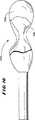
(i.単一の予め形成された展開可能な構造物)
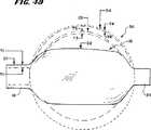
図4Aに示される実施態様において、構造物56は、ポリウレタン材料から作製された伸長されたチューブ16を備える。このチューブ16は、末端領域18および20を備える。この領域の各々は、第1の直径(図4AにおいてD1と名付けられる)を有する。このチューブ16はさらに、中間の予め形成された領域22を備える。この予め形成された中間領域22の直径は、熱および圧力への曝露によって、第1の直径D1よりも大きい拡大した直径(図4AにおいてD3と名付けられる)を有する通常に拡大した形状へと拡大されている。通常に拡大した形状D3は、内部身体領域の内側に配置される前に、野外環境において存在する。
【0028】
図5が示すように、チューブ16を、ポリウレタン(または別の好ましい)材料から、例えば、標準的ポリマー押し出しおよび成形プロセスによって、まず形成する。図6および図7が示すように、形状領域22を、この領域22を取り付け具または鋳型10中で熱に曝露して作製しながら、内側に正の圧力をこの領域22内のチューブ16に適用する。取り付け具10は、空洞24を備え、この空洞中に、領域22が存在し、熱および圧力を適用される。空洞24は、この領域22が、取り付け具10における内側の圧力によって膨張させられた場合にとると意図されるジオメトリを有する。例示された実施態様において、ほぼ球面の形状が、示される。
【0029】
空洞24を取り付け具10自体の熱エネルギーの供給源120に連結することによって(図7が示すように)か、または熱い気流もしくは等価物を空洞24中に伝達することによって、熱を適用し得る。選択される温度は、このチューブの材料が、軟化し、そして形成する温度である。
【0030】
軟化が生じる温度の範囲は、使用されるポリマー性材料の特定の組成に依存する。例えば、ポリウレタンについて、軟化温度は、約50℃〜約190℃の範囲にある。所定の可塑性材料についての軟化温度の範囲を操作することは、経験的に決定され得る。
【0031】
図7が示すように、熱軟化状態でかつ空洞24中に制限される間に、一方の末端領域18が、加圧流体の供給源34に連結される。この供給源34に連結されていない他方の末端領域20は、キャップ122を用いて密閉されるか、または他の方法でブロックされて、チューブ16中に加圧流体を保持する。好ましくは、この加圧流体は、気体または不活性ガスであり、図7においてAで示されている。
【0032】
圧力の大きさは、用いられるエラストマ材料の壁の厚さおよび他の物理的特徴に依存して変化する。圧力は、チューブ材料のバースト強度より小さくあるべきである。代表的に、5〜1000psiの範囲の空気圧が用いられ得る。
【0033】
チューブ16への圧縮空気Aの導入は、図7に示すように、空洞24において熱軟化領域22を外向きに展開させるかまたはふくらませる。空洞24は、熱軟化領域22が展開し得る範囲を限定する。領域22は、展開の際、空洞24のジオメトリに一致する。空洞24における熱軟化材料の展開は、領域22が新しい展開形状(図4Aに示される拡大された直径D3を有する)を獲得する場合、領域22における材料の応力を均一に軽減する。
【0034】
加圧された流体を、拡大された直径D3を維持するために適用しながら、熱の適用を終了し、そして領域22は冷却される。領域22は、周囲の空気の流れにより、または冷却空気の加圧ストリームにより冷却され得る。あるいは、空洞24は、そこを通って冷却液が循環され得る内部通路を備え得る。冷却が生じる速度は、プロセス全体の時間に影響を及ぼす。
【0035】
冷却後、加圧された流体の適用は終了される。ここで、予め形成された構造56は、空洞24から取り出される。
【0036】
構造56の通常に展開した形状の特徴は、他の技術により達成され得る。例えば、構造56は、浸漬、ロストワックス鋳造または射出成形により形成され得る。
【0037】
固定具10からの取り出しの際、構造56は、カテーテルチューブ50の遠位端54に固定される。カテーテルチューブ50の構造は、変化し得、そしてそれ自体は本発明には重要でない。カテーテルチューブ50のための材料は、内側本体領域への構造56の進行を容易にするように選択される。カテーテルチューブ56は、例えば、ビニル、ナイロン、ポリエチレン、イオノマー、ポリウレタンおよびポリエチレンテトラフタレート(PET)のような標準的な可撓性の医療用プラスチック材料を用いて構築され得る。カテーテルチューブ50または、より大きな剛性を与え、これによりその操作を助けるために、より硬質の材料を含み得る。この目的に用いられ得るより硬質の材料としては、KevlarTM材料、PEBAXTM材料、ステンレス鋼、ニッケル−チタン合金(NitinolTM材料)、および他の合金が挙げられる。
【0038】
例示される実施態様(図4Aに示すのが最適)において、カテーテルチューブ50は、その中に補助チューブ58が固定される内部空洞60を備える。カテーテルチューブ50が1つより多い内部ルーメンを有し得、そして例えば、複数のルーメンのアレイを有し得ることが理解されるべきである。例示の実施態様において、補助チューブ58は、内部空洞60を通って、そしてカテーテルチューブ50の遠位端54を超えて展開する。チューブ16の一方の末端領域18は、カテーテルチューブ50の遠位端54に固定され、他方の末端の領域20は、補助チューブ58の自由展開末端62に固定される。末端領域18および20は、例えば、接着性結合プロセスまたは熱結合プロセスを用いて固定され得る。
【0039】
構造56の内部で吸引すること(すなわち、負の圧力)により、存在する気量を除去し、そして領域22の直径を、その通常に展開した形状D3から、実質的に折りたたまれ、膨張していない直径D2に減少させる。折りたたまれた直径D2は、熱および圧の成形プロセスの間の形成に起因して、依然として、押しだし成形されたかまたは鋳型成形された直径D1とは異なっている。実質的に折りたたまれるかまたは膨張していない場合、構造56は、標的化された海綿質領域に挿入されるのに理想的な、低いプロファイル(low profile)を表す。
【0040】
この低いプロファイルは、所望の場合、収縮した導入スリーブ内に、構造56を納めることにより、もしくはシリコーンのような潤滑物質で構造56をコートすることにより、またはその両方により、挿入を補助するためにさらに減じられる得る。
【0041】
図3および4に示すように、カテーテルチューブ50の内部空洞60は、流体、例えば、滅菌生理食塩水または放射線不透過性造影剤(これは、構造56のX線可視化を可能にする)の供給源68に(継手122を介して)連結され得る。内部空洞60は、領域22に流体を運ぶ。所定の閾値(図10において、V(D3)で示される)までのその領域内の容積の増加は、中間領域22を折りたたまれた直径D2から、形状および直径D3を有する、通常の(すなわち、拡大はしたが拡張はしていない)ジオメトリまで回復させる。
【0042】
その通常に拡大した形状D3にある場合、領域22における構造56の材料は顕著に伸張も緊張もしていない。なぜなら、それは、予め、応力軽減状態で、空洞24においてこのジオメトリに展開されていたからである。
【0043】
展開半径の大きさ(つまり直径D3)は、空洞24内の熱および内部圧力への曝露によりもたらされる、領域22における直径の相対的な増加に依存する。押しだし成形されたかまたは鋳型成形されたチューブの直径D1と直径D3との間の相対的な増加は、チューブが直径D3を超えて展開した場合、チューブ長およびセグメントのジオメトリを提供するために少なくとも5%であるべきである。
【0044】
図4Bに示すように、空洞24における圧力下の熱軟化材料の展開に起因して、構造56の壁厚は、均一でない。領域22は、その通常に拡大された直径D3の場合、最小の壁厚T3を有する。これは、チューブ86の通常の押しだし成形されるかまたは鋳型成形された壁厚(T1)よりも薄い。
【0045】
閾値圧力P(t)での加圧された流体の構造56への持続的な体積流は、構造56の内部容積を増加させるために継続される。その容積が増大するにつれて、構造56の成形された領域22は通常の直径D3を超えて、図4でD4と示された、拡張した形状およびジオメトリへと拡大し続ける。閾値圧力P(t)は、容積がD3とD4との間で増加する場合、概して容積として一定に保たれる。容積が制御される(すなわち、実質的にD4を超えないように制御される)限り、外部の圧力調節装置は必要ない。実質的に定圧でD3とD4との間の容積展開は、構造56の物質的特性によって、生じ、なんらかの外部圧制御機構によるのではない。
【0046】
D3とD4との間でのその領域における構造の拡大は、領域22における材料を、その応力軽減状態を超えて伸張させる。結果的に、拡張したジオメトリD4での壁厚T4は、通常に拡大した直径D3の最小壁厚T3よりも薄い。しかし、この拡張ジオメトリは一般に空洞24(これは、例示された実施態様においては、球状である)により指示された予備形成された形状を維持する。
【0047】
D3とD4との間の展開領域では、実質的に一定のP(t)での流体容積の添加は、材料を伸張し、構造56の半径を増加させ、そして壁厚を減少させる。
【0048】
材料の応力は増大するその領域においてD3とD4との間で伸展する力、構造56は、骨の内側にある場合、漸増的により大きな表面および容積をとり、これにより周囲の海綿質を圧縮する。海面質内での膨張は、骨の外側と、同じ閾値圧力P(t)で生じ得る。しかし、骨の内側の限界膨張圧力P(t)の増大は、海面質の密度および圧縮に対する海綿質の抵抗性に起因して、必要とされ得る。この場合、所定の材料および構造56についての圧力対容積曲線の形は、D3とD4との間の曲線のほぼ水平な部分が、図10の想像上の線で示されるようにY軸で上向き移動することを除いて、図10に示されるのと本質的に同じままである。一般的言及として、骨内側の閾値圧力は、構造56の材料特性および海綿質の存在に起因する任意の追加された抵抗により決定される。
【0049】
D3とD4との間の距離(図10のX軸に沿う)は、壁が実質的に定圧条件および材料応力の増加を伴ってで、破損無く、海綿質を圧縮し、伸張し得る程度を規定する。容積が実質的に一定の閾値圧力P(t)で増加する場合、その構造の直径が拡張した直径D4を超えてさらに顕著に拡大するにつれて、壁の破損が、より高い確率になる。材料の弾性が最大伸長に近づくほど、または材料の応力が最大緊張強度に近づくにつれて、構造56は、もはや、その容積を増加し得ないときがくる。これらの最大値のいずれかに達したとき、壁の破損が起こる可能性が高い。
【0050】
骨の内側での展開の間の図10におけるD3とD4との間の距離は、上記の、3つの物理的特性および機械的特性(展開、形状および靭性)の同時発現である。例えば、必要な弾性および形状を有するが、必要な靭性を欠く材料は、海綿質により引き起こされる摩耗および引き裂きに起因して形状D4に達し得ない。
【0051】
(ii.予備形成複合展開可能構造)
図4に示されるような、単一の展開可能領域22を有する展開可能体56を用いて、所定の海綿質領域内の所望された均一性および面積の圧縮を達成することは、困難であり得る。
【0052】
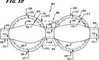
図12は、予備形成された複合構造80が、その長さに沿って間隔を空けて配置された、セグメント化された、展開可能領域82および84を備えることを示す。構造80は、より長い縦断面を提供し、これに沿って容積が増加され得る。
【0053】
複合展開可能構造80は、ポリウレタン材料またはエラストマ材料のチューブ86(図5に示すチューブ16のような)を押し出し成形または鋳型成形することにより作製される。好ましい実施態様では、このチューブ86は、ポリウレタン材料から形成される。このチューブは、通常の押しだし成形された壁厚(T5)および通常の押し出し成形された外径(D5)を有する(図12に示すように)。
【0054】
セグメント化された成形された領域82および84は、図13に示されるように、チューブ86の中間領域88を、固定具すなわち鋳型90の内側で熱および内部の正の圧力に暴露することにより作製される。例示された実施態様において、固定具90は、中間チャネル96を備える2つの空洞領域92および94を有する。中間領域88は空洞92および94ならびにチャネル96に位置する。
【0055】
空洞領域92および94ならびにチャネル96は、熱の供給源120に暴露され、領域88の材料を軟化させる。熱軟化した場合(以前に記載した様式で)、チューブ86の内部は、供給源34からの正の圧力をかけられる(これも以前に記載されたように)。領域88における材料は、空洞92および94ならびにチャネル96内で膨張または伸長する。一旦、冷却されそして固定具90から取り出されると、構造80は、図3および4において示された構造56と同じ様式で、カテーテルチューブ50の遠位端に接着され得る。
【0056】
構造80は、外気環境において、直径D7(図12において想像上の線で示される)を有する通常の展開形状を有する。領域82および84についての通常の形状および直径D7は、一般的に、それぞれ、空洞92および94の形状および寸法と対応する。
【0057】
構造80から空気を除去して内部を減圧した場合、構造80は、図12において、想像上の線D6に示される、実質的に折りたたまれ、そして膨張していないジオメトリをとる。領域88に対する熱および圧力の適用に起因して、領域82および84のそれぞれについての直径D6は、もとの押し出し成形されたチューブ86の通常の押し出し成形されたまたは鋳型成型された外径D5よりも大きい。
【0058】
領域82および84は、チューブの首部分98により隔てられ、チューブの首部は構造80を2つの展開可能な領域82および84にセグメント化する。減圧下で実質的に折りたたまれているかまたは膨張していない場合、構造80は、標的化された海綿質領域への挿入に理想的な、低いプロファイルを示す。
【0059】
チューブ86中への流体を戻して導入することにより、折りたたまれた直径D6から通常の、拡大されてはいるが膨張していないジオメトリ(図12における想像上の線D7に示される形状および直径を有する)へ、領域82および84のそれぞれが回復する。
【0060】
例示される実施態様において、第1および第2の成型された領域82および84は、ほぼ同じ展開半径を有し、従って同じ非拡張形状および直径D7を有する。あるいは、それぞれの領域82および84は、異なる膨張半径を有し得、従って異なる非拡張形状および直径を有し得る。にもかかわらず、通常の非拡張直径D7にある場合、領域88における構造80の材料は、顕著には伸張も緊張もしない。なぜなら、領域82および84は、応力減少状態において、空洞92および94におけるこのジオメトリへ、予め展開されたからである。
【0061】
構造56との組み合わせにおいて前に説明されたように、領域82および84は、異なる空洞内で熱および内部圧力により成形され、異なるジオメトリ、例えば、円筒もしくは楕円筒状のジオメトリ、または非球状、非円筒状もしくは非楕円筒状のジオメトリをとり得る。このジオメトリは、内一のまたは複合型のいずれかの曲率を有し、および対称または非対称のいずれかのジオメトリで有り得る。当然ながら、2より多いセグメント化された領域82および84が、チューブ86の長さに沿って形成され得る。
【0062】
それぞれの成形された領域82および84は、通常に拡大されたが拡張はされてないジオメトリD7の場合、最小の壁厚(図12中T7で示される)を有する。空洞92および94における圧力下での熱軟化材料の展開に起因して、この壁厚は均一ではない。すなわち、T7は、チューブ86の通常の押し出し成形されたかまたは鋳型成形された壁厚T5よりも薄い。領域82および84についての最小の壁厚T7は、同じかまたは異なり得る。
【0063】
拡大されたが拡張されていないジオメトリの場合、首領域98は、チューブ86の通常の押し出し成形されたかまたは鋳型成形された直径D5と等しいかまたはそれより大きい外径(図14においてD9で示される)を有する。固定具90におけるチャネル96のサイズは、直径D9の大きさを決定する。空洞92および94中の圧力下での隣接領域82および84における熱軟化材料の展開に起因して、首領域98(チャネル96における圧力下で展開する)は、チューブ86の通常の押し出し成形されたかまたは鋳型成形された壁厚T5より薄いかまたはこれと等しいが完全に成形された領域82または84のいずれかの最小壁厚T7よりは依然として厚い、壁厚(図12においてT9で示される)を有する。
【0064】
従って、形成された複合体構造80は、その長さに沿って、非均一な最小壁厚の領域を有する;すなわち、T5≧T9>T7である。この形成された複合構造80はまた、首領域98によりセグメント化された、同じかまたは異なる拡大された外径(D7)の複数の展開可能領域82および84を提供する。ここで、D6>D5;D7>D6;およびD7>D9である。
【0065】
閾値量の定圧P(t)で流体容積を適用することを続け、それにより構造80の容積を増加させることにより、構造80の成形された領域82および84は、拡張された形状およびジオメトリ(図12においてD8で示される)へ、直径D7を超えて拡大し続ける。壁厚T7はさらに減少し、そしてT8に近づく。領域82および84が直径D8に近づくにつれて、首領域98の直径D9は、図12に示すように、直径D10へ同様に増加し、海綿質とのより均一な、拡大された表面を提供する。
【0066】
直径D7を超える構造80の拡大は、領域82、84および98における材料を、その応力軽減状態を超えて伸張させるが、領域82および84の拡張されたジオメトリは、空洞92および94により示される予備形成された形状を、重要な点に関しては維持する。構造56に関連して前に説明されたように、領域82と84における材料は、通常の直径D7の所望の形状において既に応力軽減されている。以前に説明したように、拡張した直径D8への拡大は、実質的に一定の圧力(図10が例証するように)および増加する材料応力で生じる。
【0067】
実質的に一定の増加率の圧力条件での伸張の程度は、所望の完全に拡張した直径D8を達成するために仕立てられ得る。最終的な、完全に拡張した直径D8は、標的化された海綿質領域の寸法に適合するように選択され得る。直列にセグメント化された領域82および84の制御された伸張は、単一の非セグメント化領域(すなわち、首領域98のないもの)よりも小さい大径を有する海綿質の等積圧縮を提供し得る。別の方法で言えば、セグメント化された領域82および84は、所定の膨張容積に展開された場合、等しい膨張容積へ展開された球より小さい直径を有する。
【0068】
D7とD8との間の領域における展開の間、構造80は、構造56と同様に、骨の内側にある場合、漸増的により大きい表面および容積をとり、これにより周囲の海綿質を圧縮する。海綿質における膨張は、骨の外側と同じ閾値圧力P(t)で生じ得る。しかし、骨内部の閾値膨張圧力P(t)の増大が、海綿質の密度および圧縮に対する海綿質の抵抗に起因して、必要とされ得る。
【0069】
(iii.複合展開可能構造)
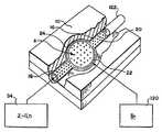
以前の実施態様において、構造56または80の材料は、展開、形状および靭性のすべての所望の物理的および機械的要件を組み込むように選択される。図16は、所望の物理的および機械的要件が異なる材料の使用により区分けされている複合の展開可能構造130を例示する。
【0070】
図16に示すように、複合構造130は、展開および形状の1つ以上の所望の要件を満たす第1の材料から作製された内部の展開可能体132を含む。複合構造130は、所望の靭性要件を満たす第2の材料から作製された外部の展開可能体またはシェル134を備える。シェル134は、内部展開可能体132を包み、そして海綿質との接触に起因する、表面の摩耗、引き裂き、または穿刺から防御する。
【0071】
シェル134は、種々の浸漬技術、塗装技術または被膜技術により内部体の表面に供される材料を含み得る。あるいは、シェル134は、その中に内部本体132が配置前に置かれる袋(bagまたはsock)を含み得る。シェル134のための材料は、例えば、ゴム、シリコーン、エチレン酢酸ビニル、ポリウレタン、ポリエチレン、またはマルチフィラメント織材、もしくは織布あるいは他のポリマー材料を含み得る。
【0072】
複合構造130は、靭性要件から展開および形状の要件を分離することを可能にする。腎性要件を完全にまたは部分的に満たさない材料は、それでも、内部本体132に用いられ、構造130の展開および形状要件を最適化し得る。内部体132は、海綿質に最適化された展開および形状の特徴を付与し、他方、シェル134は、複合構造130全体に最適化された靭性特徴を付与する。
【0073】
(II.予め形成された展開可能構造の骨における配置)
構造56または80または130は、米国特許第4,969,888号および第5,108,404号(参考として本明細書中で援用される)の教示に従って骨中に挿入され得る。図8が示すように、アクセスは、例えば、椎体26の一側にアクセス口64を穿孔することにより達成され得る。これは後外側アプローチと呼ばれる。あるいは、アクセス口はいずれかの茎(pedicle)42を通過し得る。これは経茎アプローチと呼ばれる。
【0074】
ガイド鞘またはカニューレ66は、アクセス口64と連絡して置かれる。カテーテルチューブ50は、構造(図8は構造56を示す)を海綿質32と接触して配置するように、カニューレ66を通って進められる。構造56は、配置の間、その通常に折りたたまれた、膨張していない状態(図8において仮想線の直径D2として示される)にある。この様式のアクセスは、非観血的な最少侵襲手順または観血的手順を用いて達成され得る。
【0075】
カテーテルチューブ50の材料は、海綿質32への展開可能構造56の前進を容易にするように選択される。カテーテルチューブ50は、例えば、ビニル、ナイロン、ポリエチレン、イオノマー、ポリウレタン、およびポリエチレンテトラフタレート(PET)のような標準的な可橈性の医療用プラスチック材料を使用して構築され得る。カテーテルチューブ50はまた、より大きな剛性を付与し、これによりその操作を補助するために、より硬質の材料を含み得る。この目的に使用され得るより硬質の材料には、ステンレス鋼、ニッケル−チタン合金(NitinolTM材料)、および他の金属の合金が含まれる。
【0076】
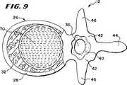
図8が示すように、拡大されているが拡張されていないジオメトリ(図8における仮想線の直径D3)、そして極限には最大拡張されたジオメトリ(図8における直径D4)への構造56の展開は、引き続いて、椎体26において海綿質32を圧縮する。圧縮は、海綿質32において内部空洞70を形成する。図9が示すように、後に続く構造56の折りたたみおよび除去は、空洞70を、充填材料(例えば、骨接合剤)を受容する状態に残す。この骨接合剤は、硬化した場合に皮質骨32のための改善された内部構造支持体を提供する。
【0077】
図8に示される海綿質32の圧縮はまた、周囲の皮質骨28に対して内圧(interior force)を働かせる。内圧は、骨折し圧縮された骨を、その元の破損前の状態または他の所望の状態まで戻すかまたはその近辺に持ち上げ得るかまたは押し得る。
【0078】
椎体26の場合、海綿質32の劣化により、上板および下板(図2においてTPおよびBPと示す)が圧縮され、または互いに近くに移動し、板TPと板BPとの間の通常な生理学的な高さが減少し得る。この状況で、構造56が働かせる内圧は、それが海綿質32を圧縮するにつれて、上板および下板TPおよびBPの一方または両方をさらに離して移動させ、このことによりそれらの間の空間(通常な生理学的距離にまたはその付近にある)を回復させる。
【0079】
図11に示されるように、別の実施態様において、剛性部材またはスタイレット74は、補助チューブ58のルーメン72を通って挿入され得る。補助チューブは構造56内に包まれている。スタイレット74は、例えば、ステンレス鋼または鋳型成形されたプラスチック材料から作製され得る。スタイレット74の存在は、図8が示すように、標的化された骨領域中へガイド鞘66を通過する間、構造56を、所望の遠位方向に真っ直ぐにされた状態に保つために役立つ。
【0080】
図11にさらに示されるように、スタイレット74は、その遠位領域を通常には曲げるように、予め形成された記憶を有し得る。この記憶は、ガイド鞘66内に閉じ込められている場合、克服されてスタイレット74は真っ直ぐになる。しかし、構造56および予め形成されたスタイレット74が、ガイド鞘66を自由に前進し、そして標的化された領域中に進入すると、予め形成された記憶がスタイレット74を曲げる。曲がったスタイレット74は、補助チューブ58を曲げ、そのことにより周りの展開可能構造56の主軸76が、アクセス経路(すなわち、ガイド鞘66)の軸78に対してシフトする。構造56の内部に位置付けされた、予め曲げられたスタイレット74は、標的化された領域内での構造56の配向を変更することを補助する。このことにより、構造56を、椎体26の天然の軸と、ほぼ揃えられた関係で配向することが可能になる。骨(例えば、椎体26)内のより中心に位置する空洞70が確立され得る。これは、骨接合剤を充填された場合、椎体26の中間領域を横切るより均一な支持体を提供する。これにより、負荷に耐える椎体26の能力は向上する。内部容積における海綿質32の対称的圧縮はまた、皮質骨32に対するより均等で均一な内圧を働かせ、破損し圧縮された骨を持ち上げるかまたは押す。
【0081】
より少ない量の海綿質圧縮が示されるときがある。例えば、処置される骨疾患が例えば虚血壊死に位置する場合、または血液供給の局所的喪失が、その限定された領域で骨を殺傷している場合、展開可能構造56または80または130は、より少ない量の全骨(total bone)を圧縮し得る。これは、処置を必要とする疾患領域がより小さいからである。
【0082】
別の例外は、規定された形状の固体材料(ヒドロキシアパタイトおよび関節全置換における構成成分のような)の挿入を改善するための展開可能構造56または80または130の使用に見出される。これらの場合、構造の形状およびサイズは、挿入される材料の形状およびサイズによって規定される。
【0083】
なお別の例外は、上述のように、同時係属中の米国特許出願第08/485,394号に開示されるように、治療物質の送達を補助するための空洞を作製するための、骨における展開可能構造の使用に見出される。この場合、海綿質は罹患していてもしていなくてもよいし、また有害な影響を受けていても受けていなくてもよい。健康な海綿質は、重要な治療目的を有する薬物または成長因子の送達を改善するために、顕著な圧縮により犠牲にされ得る。この適用において、展開可能構造56または80または130は、送達されようとする、所望の量の治療物質によって選択される。この場合、薬物を内部に有する骨は、その薬物が作用し骨が治癒する間、標準的な方法により支持される必要があり得る。
【0084】
(III.一回使用)
標的化された身体領域における最初の使用の間の、本明細書に記載される展開可能構造56または80または130のいずれか1つの拡張は、この構造を構成する材料への応力を発生させる。標的化された身体領域における最初の使用の間に操作上の負荷により生じた材料応力は、その構造の予め形成された形態を相当変更して、その構造の将来の性能を予測不能にし得る。
【0085】
例えば、一回の使用の間の骨内での展開は、周囲の皮質骨および海綿質との接触を生じる。材料の優れた機械的特性に関わらず、この接触は、そのうちには、構造に損傷を与えて、検出を免れ得る局所的な脆弱領域を生じ得る。局所的な、より低密度の海綿質領域は、結果的に、展開および構造に対する応力が異なる領域を発生させ得る。局所的な脆弱領域または応力が異なる領域の存在により、後の使用の間に、全体的な構造的欠陥が予測不能に引き起こされ得る。
【0086】
さらに、一回の使用の間での血液および組織への曝露は、その構造または結合したカテーテルチューブの上または内部に生物学的成分を捕獲し得る。洗浄およびその後の殺菌にも関わらず、捕獲された生物学的成分の存在は、容認し難い発熱性反応に至り得る。
【0087】
その結果、最初の使用後、その構造は、後の使用の間にその所望の形に達することが、一貫しては信頼され得ず、そうでなければ、確立された性能および滅菌の仕様に適合し得ない。再滅菌後でさえの発熱反応の可能性とあいまって、一回の使用の間に引き起こされる材料の応力および損傷の効果により、骨への配置のためにこれらの展開可能構造を運ぶデバイスに一回使用の制限を課すことが、合理的に正当化される。
【0088】
複数回の使用により引き起こされる潜在する有害な結果(疾患の伝播、または材料の応力および不安定性、または減少したかもしくは予測不能な性能を含む)から患者を保護するため、本発明はまた、使用の前に、一回使用ツール48(図3にも示される)を格納するためのキット100(図14および15を参照)を提供する。図14に示されるように、ツール48は展開可能構造を収容する。図14は、例示のために、本明細書に記載のような構造56を示す。ツール48は、以前にも記載したように、展開可能構造80または130を収容し得ることが理解されるべきである。
【0089】
例示される実施態様(図14および15を参照)では、キット100は内部トレイ108を備える。トレイ108は、その最初の使用前の滅菌および格納の間、平坦に配置された真っ直ぐな状態でツール48を保持する。トレイ108は、ダイ切断された厚紙または熱成形プラスチック材料から形成され得る。トレイ108は、間隔を設けた1またはそれ以上のタブ110を備える。タブ110は、所望される平坦に配置された真っ直ぐな状態で、カテーテルチューブ50および展開可能構造56を保持する。
【0090】
キット100は、外部環境と接触しないようにトレイ108を包むため、熱などにより周辺を封鎖された内側包装112を備える。内側包装112の一方の端は、従来型の剥ぎ取り式シール114を備えて、使用時のトレイ108への素早いアクセスを提供する。アクセスは、好ましくは、手術室内部などの無菌環境で起こる。
【0091】
キット100はまた外側包装116を備える。外側包装116もまた、内側包装112を包むよう、熱などにより周辺封鎖される。外側包装116の一方の端は、内側包装112へのアクセスを提供するための従来型の剥ぎ取りシール118を備える。このシールは、プローブ102の切迫した使用を見越して、プローブ102自体の無菌性を侵すこと無く、外側包装116から除去され得る。
【0092】
内側包装112および外側包装116の両方(図15を参照)は、各々、周辺が封鎖された頂部シート120および底部シート122を備える。例示された実施態様では、頂部シート120は、キット100の内容物を視覚による同定を可能にするよう、ポリエチレンまたはMYLARTM材料のような透明プラスチックフィルムから作られる。底部シート122は、ETO滅菌ガスに対して透過性である材料(TYVEKTMプラスチック材料(DuPontから入手可能))から作られる。
【0093】
滅菌キット100はまたラベルまたは添付書106を有し、これは、キット100の内容物の再利用に対して積極的に警告するために、「一人の患者に対してのみ使用すること(またはこれに相当する表現)」という表示を含む。ラベル106にはまた、ツール48を再滅菌しないように積極的に指示してあることが好ましい。ラベル106にはまた、使用の際にツール48およびキット100の全内容物を、適用される生物学的廃棄物処理手順に従って廃棄するように、医師またはユーザーに指示してあることが好ましい。キット100に梱包されたプローブ102の存在により、ツール48が無菌であり、以前に使用されていないことが、医師またはユーザーに証明される。このことにより、医師またはユーザーは、展開可能構造56が確立された性能および無菌性の仕様を満たし、使用のために展開された場合、所望の形を有することを確信する。
【0094】
ラベル106にはまた、医師に対し、上記した様式で海綿質を圧縮するための展開可能構造56(または80または130)の使用に関して指示してあることが好ましい。例えば、ラベル106には、医師に対して、海綿質を圧縮し、空洞を形成するために、骨の内側でその構造を展開するよう指示してある。ラベル106にはまた、医師に対して、空洞に材料(例えば、骨接合剤、異種移植材料、合成骨置換物、薬物、または固化状態に硬化する流動可能な材料)を充填するように指示され得る。
【0095】
本発明の特徴は、上述の特許請求の範囲に記載される。
【0096】
本発明は、その精神または本質的な特徴から逸脱することなく幾つかの形態に具体化され得る。本発明の範囲は、具体的な説明よりむしろ添付の特許請求の範囲内に規定される。従って、特許請求の範囲の意味および等価の範囲内に入る全ての実施態様は、特許請求の範囲によって包括されることが意図される。
【図面の簡単な説明】
【図1】 図1は、椎骨体の冠状図である。
【図2】 図2は、図1に示した椎骨体の側面図である。
【図3】 図3は、本発明の特徴を具体化する展開可能な構造をその末端にて保有するツールの平面図である。
【図4A】 図4Aは、図3に示されるツールによって保有される展開可能な構造の拡大側面図である。
【図4B】 図4Bは、図3に示されるツールによって保有される展開可能な構造の拡大側面図である。
【図5】 図5は、図4Aに示される展開可能な構造内に形成される前に、ポリウレタンまたはエラストマー材料から作製されるチューブの斜視端面図である。
【図6】 図6は、形状形成固定具内に配置される、図5に示されるチューブの上面斜視図であり、その一部が分解されてその内部の観察が可能となっている。
【図7】 図7は、図6に示される形状形成固定具の上面斜視図であり、使用時には熱および圧力をチューブの領域に適用し、成形された展開可能な領域を形成する。
【図8】 図8は、展開可能な構造の膨張の結果として海綿質を圧縮するために配置される図3に示されるツールと共に、図1に示される椎骨体の冠状図である。
【図9】 図9は、ツールを取り外した際の図8に示した椎骨体の冠状図であり、展開可能な構造による海綿質の圧縮によって形成される空洞を示す。
【図10】 図10は、構造の内部に適用される増加する圧力の、構造の展開した容量に対する効果をプロットするグラフである。
【図11】 図11は、海綿質を圧縮するために配置されたツールと共に、図8に示した椎骨体の冠状図であり、ここで、屈曲可能なスタイレットは海綿質内の展開可能な構造の配向を変更する。
【図12】 図12は、複合構造の側面図であり、この構造はその長さに沿って間隔をあけた幾つかの展開可能なセグメントを含む。
【図13】 図13は、図12に示される構造を作製するために押出しされたかまたは成形されたチューブに圧力および熱を適用するために使用される形状形成固定具の上面斜視図である。
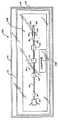
【図14】 図14は、使用前に、密閉され滅菌された環境において、図3に示されるツールを保持するキットの上面図である。
【図15】 図15は、図14に示されるキットの分解組立図である。
【図16】 図16は、複合した展開可能な構造の部分的に断面で示した側面図である。[0001]
(Field of Invention)
The present invention relates to a deployable structure that, in use, is placed within the internal body regions of humans and other animals.
[0002]
(Background of the Invention)
The deployment of an expandable structure, commonly referred to as a “balloon”, within the sponge is known. For example, U.S. Pat. Nos. 4,969,888 and 5,108,404 are deployed in cancellous for fixation of bone fractures in humans and animals or other osteoporotic and non-osteoporotic conditions. Devices and methods are disclosed that use possible structures.
[0003]
(Summary of the Invention)
If the deployable structure is placed in cancellous, it should withstand deployment and expansion without breaking. Furthermore, such a structure should, when expanded, generally conform to the shape of the space inside the bone in which the structure is placed. Furthermore, such a structure should allow preferential deployment to areas of lowest bone density. Exposure to cancellous quality also requires materials that exhibit excellent resistance to surface wear and tensile stress.
[0004]
A deployable structure made from an elastomeric material, e.g. polyurethane, can be pre-formed to the desired shape, e.g. by exposure to heat and pressure, and can withstand controlled deployment and further expansion within the sponge without breaking However, on the other hand, it has been discovered that it exhibits excellent resistance to surface wear and puncture when contacting cancellous.
[0005]
The features and advantages of the invention are set forth in the following description and drawings, and in the appended claims.
[0006]
Detailed Description of Preferred Embodiments
This preferred embodiment describes improved systems and methods that embody features of the present invention in the context of treating bone. This is because these new systems and methods are advantageous when used for this purpose. However, aspects of the invention can be advantageously applied for diagnostic or therapeutic purposes in other areas of the body.
[0007]
These novel systems and methods are described in more detail in the context of human vertebral treatment. Of course, other human or animal bone types can be treated in the same or equivalent manner.
[0008]
FIG. 1 shows a coronal view (top view) of the
[0009]
As shown in FIGS. 1 and 2, the
[0010]
A spinal canal 36 (see FIG. 1) is located on the back (ie, dorsal) side of each
[0011]
It can be shown that the sponge in this vertebral body is compressed due to disease or trauma. For example, the compression can be used to form an internal cavity that can be filled with a filling material (eg, a flowable material that hardens and solidifies (eg, bone cement, allograft tissue, self May contain graft tissue, hydroxyapatite, or synthetic bone substitutes) as well as drugs, or combinations thereof, and may provide improved internal support for cortical bone, or other therapeutic functions, or both . Cancellous compression also exerts internal pressure on the cortical bone, raising or pushing the broken compressed bone back to its original (or other desired) state before failure It becomes possible to be close to it.
[0012]
(I. Preformable expandable structure)
FIG. 3 shows a
[0013]
(A. Desired physical and mechanical properties)
The material from which this
[0014]
(I. Development characteristics)
The first desired property for this structural material is the ability to expand or otherwise increase its volume without breaking. This property causes the
[0015]
The deployment characteristics for this material are characterized, for example, by a maximum elongation characteristic, which indicates the maximum degree of elongation that the material can accommodate before failure. A maximum elongation of at least about 300% prior to material failure provides the ability to expand to the volume required to compress cancellous as well as to expand adjacent cortical bone. Materials with a maximum elongation of less than about 300% tend to show failure in an expanded volume that is insufficient for the desired bone compression volume.
[0016]
(Ii. Shape characteristics)
A second desired property for the material of this
[0017]
The shape of the
[0018]
In some cases, when creating a cavity, it may be desirable to also move or transpose cortical bone to achieve the desired therapeutic result. Such movement is not inherently harmful. This term is used herein to indicate that the desired therapeutic result is achieved. By definition,
[0019]
One general consideration is that if the bone disease that causes (or is at risk of) damage is loss of cancellous mass (as in osteoporosis), the deployment of the
[0020]
Another general guideline for selection of the deployed shape of the
[0021]
For practical reasons, the deployed shape of the
[0022]
The optimum degree of shaping can be achieved as described in more detail below by the choice of materials and by special manufacturing techniques such as thermoforming or blow molding.
[0023]
(Iii. Toughness properties)
A third desired property for the material of this
[0024]
This property can be characterized in various ways. For example, a Taber abrasion resistance value of less than about 90 mg loss indicates resistance to breakage when in contact with cancellous. 70mmThree A rotating drum wear resistance value of less than also indicates resistance to breakage when in contact with sponge. This property can be further characterized, for example, by Elmendorf tear strength greater than about 280 lbf / in, which indicates resistance to breakage caused by cancellous wear. This property can also be characterized by a shore hardness value of less than about 100 mm. This value indicates the degree of elasticity, flexibility and ductility.
[0025]
Material with Taber abrasion resistance value greater than about 90 mg loss, or about 70 mmThree A material with a rotating drum wear resistance value greater than or equal to or less than about 280 lbf / in, or a material with a Shore hardness value greater than about 100 約 is not well suited for deployment in sponge. This is because failure can occur before deployment to the desired diameter.
[0026]
(B. Enhanced deployment and shape characteristics)
The deployment and shape characteristics described herein can be enhanced by selecting an elastomeric material and can be further optimized for cancellous compression. The elastomeric material also has the ability to be preformed, that is, the ability to obtain a desired shape, for example by exposure to heat and pressure, for example through the use of conventional thermoforming or blow molding techniques. Have. Candidate materials that meet this criterion include polyurethane materials, silicone materials, thermoplastic rubber materials, nylon materials, and thermoplastic elastomer materials. In the most preferred embodiment, a polyurethane material is used.
[0027]
(I. A single preformed deployable structure)
In the embodiment shown in FIG. 4A, the
[0028]
As FIG. 5 shows, the
[0029]
Heat may be applied by coupling the
[0030]
The range of temperatures at which softening occurs depends on the specific composition of the polymeric material used. For example, for polyurethane, the softening temperature is in the range of about 50 ° C to about 190 ° C. Manipulating the softening temperature range for a given plastic material can be determined empirically.
[0031]
As FIG. 7 shows, one
[0032]
The magnitude of the pressure varies depending on the wall thickness of the elastomeric material used and other physical characteristics. The pressure should be less than the burst strength of the tube material. Typically, air pressure in the range of 5-1000 psi can be used.
[0033]
The introduction of the compressed air A into the
[0034]
While applying the pressurized fluid to maintain the enlarged diameter D3, the application of heat is terminated and the
[0035]
After cooling, the application of pressurized fluid is terminated. Here, the preformed
[0036]
The normally unfolded shape features of the
[0037]
Upon removal from the
[0038]
In the illustrated embodiment (best shown in FIG. 4A), the
[0039]
By aspirating inside structure 56 (ie, negative pressure), the volume present is removed and the diameter of
[0040]
This low profile can be used to aid insertion, if desired, by placing the
[0041]
As shown in FIGS. 3 and 4, the
[0042]
When in its normally enlarged shape D3, the material of
[0043]
The magnitude of the deployment radius (ie, diameter D3) depends on the relative increase in diameter in
[0044]
As shown in FIG. 4B, due to the development of the thermosoftening material under pressure in the
[0045]
The sustained volume flow of pressurized fluid into the
[0046]
The expansion of the structure in that region between D3 and D4 causes the material in
[0047]
In the deployment region between D3 and D4, the addition of fluid volume at a substantially constant P (t) stretches the material, increases the radius of the
[0048]
The stress of the material is the force that stretches between D3 and D4 in that region, where
[0049]
The distance between D3 and D4 (along the X axis in FIG. 10) is the extent to which the wall can compress and stretch cancellous without breakage, with substantially constant pressure conditions and increased material stress. Stipulate. As the volume increases at a substantially constant threshold pressure P (t), wall failure becomes more probable as the diameter of the structure expands more significantly beyond the expanded diameter D4. As the elasticity of the material approaches maximum elongation, or as the stress of the material approaches maximum tension strength, the time comes when the
[0050]
The distance between D3 and D4 in FIG. 10 during deployment inside the bone is a co-expression of the above three physical and mechanical properties (deployment, shape and toughness). For example, a material that has the necessary elasticity and shape but lacks the necessary toughness cannot reach shape D4 due to wear and tear caused by the cancellous quality.
[0051]
(Ii. Pre-formed composite deployable structure)
With a
[0052]
FIG. 12 shows that the preformed
[0053]
Composite
[0054]
Segmented shaped
[0055]
[0056]
The
[0057]
When air is removed from
[0058]
[0059]
By introducing the fluid back into the
[0060]
In the illustrated embodiment, the first and second molded
[0061]
As previously described in combination with
[0062]
Each shaped
[0063]
For expanded but unexpanded geometry, the
[0064]
Thus, the formed
[0065]
By continuing to apply the fluid volume with a threshold amount of constant pressure P (t), thereby increasing the volume of the
[0066]
The expansion of the
[0067]
The degree of stretching at substantially constant increasing pressure conditions can be tailored to achieve the desired fully expanded diameter D8. The final, fully expanded diameter D8 can be selected to match the size of the targeted cancellous region. Controlled stretching of the series segmented
[0068]
During deployment in the region between D7 and D8,
[0069]
(Iii. Structure capable of complex development)
In previous embodiments, the material of
[0070]
As shown in FIG. 16, the
[0071]
The
[0072]
[0073]
(II. Placement of preformed expandable structure in bone)
[0074]
A guide sheath or
[0075]
The material of the
[0076]
As FIG. 8 shows, the expansion of the
[0077]
The compression of cancellous 32 shown in FIG. 8 also exerts an internal force on the surrounding
[0078]
In the case of the
[0079]
As shown in FIG. 11, in another embodiment, a rigid member or
[0080]
As further shown in FIG. 11, the
[0081]
There are times when a lower amount of sponge compression is indicated. For example, if the bone disease being treated is located, for example, in ischemic necrosis, or if a local loss of blood supply is killing bone in that limited area, the
[0082]
Another exception is found in the use of
[0083]
Yet another exception is that in the bone, as described above, to create a cavity to assist in the delivery of the therapeutic agent, as disclosed in co-pending US patent application Ser. No. 08 / 485,394. Found in the use of deployable structures. In this case, the cancellous may or may not be affected, and may or may not be adversely affected. Healthy cancellous can be sacrificed by significant compression to improve the delivery of drugs or growth factors with important therapeutic purposes. In this application, the
[0084]
(III. Used once)
Expansion of any one of the
[0085]
For example, deployment within the bone during a single use results in contact with surrounding cortical bone and cancellous. Regardless of the superior mechanical properties of the material, this contact can eventually cause localized fragile regions that can damage the structure and evade detection. Local, lower density cancellous regions can result in regions with different stresses on deployment and structure. The presence of local fragile regions or regions of different stress can cause unpredictable overall structural defects during later use.
[0086]
In addition, exposure to blood and tissue during a single use can capture biological components on or within the structure or associated catheter tube. Despite washing and subsequent sterilization, the presence of captured biological components can lead to an unacceptable pyrogenic reaction.
[0087]
As a result, after initial use, the structure cannot consistently be trusted to reach its desired shape during subsequent use, otherwise to established performance and sterilization specifications. Cannot fit. Combined with the possibility of an exothermic reaction even after re-sterilization, the effects of material stress and damage caused during a single use make it unacceptable for devices carrying these deployable structures for placement on the bone. Imposing a limit on single use is reasonably justified.
[0088]
The present invention is also used to protect patients from potential adverse consequences caused by multiple uses, including disease transmission, or material stresses and instabilities, or reduced or unpredictable performance. Before, a kit 100 (see FIGS. 14 and 15) for storing a single use tool 48 (also shown in FIG. 3) is provided. As shown in FIG. 14,
[0089]
In the illustrated embodiment (see FIGS. 14 and 15), the
[0090]
The
[0091]
The
[0092]
Both the
[0093]
The
[0094]
The
[0095]
The features of the invention are set forth in the appended claims.
[0096]
The present invention may be embodied in several forms without departing from its spirit or essential characteristics. The scope of the invention is defined in the appended claims rather than in the specific description. Accordingly, all embodiments that come within the meaning and range of equivalency of the claims are intended to be embraced by the claims.
[Brief description of the drawings]
FIG. 1 is a coronal view of a vertebral body.
FIG. 2 is a side view of the vertebral body shown in FIG.
FIG. 3 is a plan view of a tool having a deployable structure at its end embodying features of the present invention.
4A is an enlarged side view of the deployable structure carried by the tool shown in FIG. 3. FIG.
FIG. 4B is an enlarged side view of the deployable structure held by the tool shown in FIG.
FIG. 5 is a perspective end view of a tube made from a polyurethane or elastomeric material prior to being formed within the deployable structure shown in FIG. 4A.
FIG. 6 is a top perspective view of the tube shown in FIG. 5 arranged in the shape-forming fixture, and a part of the tube is disassembled so that the inside thereof can be observed.
FIG. 7 is a top perspective view of the shape-forming fixture shown in FIG. 6, and in use, heat and pressure are applied to the region of the tube to form a shaped deployable region.
FIG. 8 is a coronal view of the vertebral body shown in FIG. 1 with the tool shown in FIG. 3 positioned to compress cancellous as a result of expansion of the deployable structure.
FIG. 9 is a coronal view of the vertebral body shown in FIG. 8 with the tool removed, showing the cavity formed by cancellous compression with an expandable structure.
FIG. 10 is a graph plotting the effect of increasing pressure applied inside the structure on the deployed capacity of the structure.
FIG. 11 is a coronal view of the vertebral body shown in FIG. 8 with a tool positioned to compress the cancellous, wherein the bendable stylet is deployable within the cancellous. Change the orientation of the structure.
FIG. 12 is a side view of a composite structure that includes several deployable segments spaced along its length.
FIG. 13 is a top perspective view of a shape forming fixture used to apply pressure and heat to a tube that has been extruded or molded to create the structure shown in FIG.
FIG. 14 is a top view of the kit holding the tool shown in FIG. 3 in a sealed and sterilized environment before use.
FIG. 15 is an exploded view of the kit shown in FIG. 14;
FIG. 16 is a partial cross-sectional side view of a composite deployable structure.
Claims (12)
Translated fromJapanese該構造が、該遠位端の近傍に位置する第1の展開可能な領域、および該第1の展開可能な領域の近位方向に位置する第2の展開可能な領域をさらに有し、該第1の展開可能な領域と第2の展開可能な領域が該構造の第3の領域によって分離され、該第3の領域が、該構造が該通常に展開した形状にあるとき、および該膨張容量であるとき、該第1の領域の内部断面積および第2の領域の内部断面積と比較したとき、減少した内部断面積を有し、
そして
該第1の展開可能な領域、該第2の展開可能な領域、および該第3の展開可能な領域が、それぞれ、第1の予備形成された壁厚み、第2の予備形成された壁厚み、および第3の予備形成された壁厚みを有し、そして
該構造が、該通常に展開した形状であるとき、および該膨張容量であるとき、該第3の壁厚みが、該第1の壁厚みまたは該第2の壁厚みのいずれかより大きい、装置。An expandable structure that is preformed in a normally deployed shape and is deployable to reach an expansion capacity that is size and form for compressing the sponge beyond its normally deployed shape An apparatus comprising a wall material defining an interior space around and having a structure having a proximal end and a distal end,
The structure further comprises a first deployable region located proximate to the distal end and a second deployable region located proximal to the first deployable region; A first deployable region and a second deployable region are separated by a third region of the structure, the third region being in the normally deployed shape and the expansion Having a reduced internal cross-sectional area when compared to the internal cross-sectional area of the first region and the internal cross-sectional area of the second region,
And the first deployable region, the second deployable region, and the third deployable region are respectively a first pre-formed wall thickness and a second pre-formed wall. And when the structure is in the normally unfolded shape and in the expansion capacity, the third wall thickness is the first wall thickness. An apparatus that is greater than either the wall thickness or the second wall thickness.
可撓性材料を提供する工程、および
骨の外側に通常に展開した形状を備えた展開可能な領域を含む構造中に可撓性壁を形成する工程であって、
該展開可能な領域が、海面質を圧縮するためのサイズおよび形態の膨張容量に到達するようにその通常に展開した形状を超えて展開可能であり、該構造の近位端に隣接する第1の展開したセクション、該構造の遠位端に隣接する第2の展開したセクション、および該第1の展開したセクションと第2の展開したセクションとの間に位置する第3のセクションを含むために、取り付け具内の該展開可能な領域を、該取り付け具への熱および該展開可能な領域の内部への圧力の付与によって予備形成することを含み、該構造が、通常に展開した形状であるとき、および該膨張容量にあるとき、該第3のセクションの内部断面積が、該第1の展開したセクションおよび第2の展開したセクションのいずれかの内部断面積より小さく、そして該第3のセクションの壁厚みが、該第1の展開したセクションおよび第2の展開したセクションのいずれかの壁厚みより大きい、工程、を包含する、方法。A method of creating a deployable structure comprising:
Providing a flexible material; and forming a flexible wall in a structure comprising a deployable region with a normally deployed shape outside the bone, comprising:
The deployable region is deployable beyond its normally deployed shape to reach an expansion capacity of a size and configuration for compressing sea surface quality, and a first adjacent the proximal end of the structure A deployed section, a second deployed section adjacent the distal end of the structure, and a third section located between the first deployed section and the second deployed section. Pre-forming the deployable region in the fixture by applying heat to the fixture and pressure inside the deployable region, the structure being in a normally deployed shape And when in the expansion volume, the internal cross-sectional area of the third section is less than the internal cross-sectional area of either the first deployed section or the second deployed section, and the third section Wall thickness of transfection is, includes greater than one of the wall thickness of the expanded section and a second expanded section of the first step, the method.
Applications Claiming Priority (3)
| Application Number | Priority Date | Filing Date | Title |
|---|---|---|---|
| US8845998A | 1998-06-01 | 1998-06-01 | |
| US09/088,459 | 1998-06-01 | ||
| PCT/US1999/012120WO1999062416A1 (en) | 1998-06-01 | 1999-06-01 | Expandable preformed structures for deployment in interior body regions |
Related Child Applications (1)
| Application Number | Title | Priority Date | Filing Date |
|---|---|---|---|
| JP2008027083ADivisionJP4812786B2 (en) | 1998-06-01 | 2008-02-06 | Deployable preformed structure for placement within an internal body region |
Publications (3)
| Publication Number | Publication Date |
|---|---|
| JP2002516697A JP2002516697A (en) | 2002-06-11 |
| JP2002516697A5 JP2002516697A5 (en) | 2006-07-20 |
| JP4393706B2true JP4393706B2 (en) | 2010-01-06 |
Family
ID=22211509
Family Applications (2)
| Application Number | Title | Priority Date | Filing Date |
|---|---|---|---|
| JP2000551679AExpired - Fee RelatedJP4393706B2 (en) | 1998-06-01 | 1999-06-01 | Deployable preformed structure for placement within an internal body region |
| JP2008027083AExpired - Fee RelatedJP4812786B2 (en) | 1998-06-01 | 2008-02-06 | Deployable preformed structure for placement within an internal body region |
Family Applications After (1)
| Application Number | Title | Priority Date | Filing Date |
|---|---|---|---|
| JP2008027083AExpired - Fee RelatedJP4812786B2 (en) | 1998-06-01 | 2008-02-06 | Deployable preformed structure for placement within an internal body region |
Country Status (12)
| Country | Link |
|---|---|
| US (5) | US6607544B1 (en) |
| EP (1) | EP1083836B1 (en) |
| JP (2) | JP4393706B2 (en) |
| AT (1) | ATE484247T1 (en) |
| AU (1) | AU756969B2 (en) |
| CA (1) | CA2333761C (en) |
| DE (1) | DE69942858D1 (en) |
| ES (1) | ES2354492T3 (en) |
| IL (1) | IL140013A0 (en) |
| NO (1) | NO20006089L (en) |
| NZ (1) | NZ508401A (en) |
| WO (1) | WO1999062416A1 (en) |
Families Citing this family (365)
| Publication number | Priority date | Publication date | Assignee | Title |
|---|---|---|---|---|
| US6241734B1 (en)* | 1998-08-14 | 2001-06-05 | Kyphon, Inc. | Systems and methods for placing materials into bone |
| US6716216B1 (en) | 1998-08-14 | 2004-04-06 | Kyphon Inc. | Systems and methods for treating vertebral bodies |
| US20060100635A1 (en)* | 1994-01-26 | 2006-05-11 | Kyphon, Inc. | Inflatable device for use in surgical protocol relating to fixation of bone |
| US20030032963A1 (en)* | 2001-10-24 | 2003-02-13 | Kyphon Inc. | Devices and methods using an expandable body with internal restraint for compressing cancellous bone |
| US20030229372A1 (en)* | 1994-01-26 | 2003-12-11 | Kyphon Inc. | Inflatable device for use in surgical protocols relating to treatment of fractured or diseased bone |
| US6248110B1 (en)* | 1994-01-26 | 2001-06-19 | Kyphon, Inc. | Systems and methods for treating fractured or diseased bone using expandable bodies |
| ATE361028T1 (en)* | 1994-01-26 | 2007-05-15 | Kyphon Inc | IMPROVED INFLATABLE DEVICE FOR USE IN SURGICAL METHODS OF FIXATION OF BONE |
| WO2003059213A2 (en)* | 1994-01-26 | 2003-07-24 | Kyphon Inc. | Inflatable device for use in surgical protocol relating to fixation of bone |
| US20030157074A1 (en)* | 1994-11-16 | 2003-08-21 | Mitrani Eduardo N. | Vitro micro-organs, and uses related thereto |
| WO2006053312A1 (en)* | 1995-06-07 | 2006-05-18 | Kyphon Inc. | System and method for delivering a therapeutic agent for bone disease |
| US20050131269A1 (en)* | 1995-06-07 | 2005-06-16 | Talmadge Karen D. | System and method for delivering a therapeutic agent for bone disease |
| US20050131267A1 (en)* | 1995-06-07 | 2005-06-16 | Talmadge Karen D. | System and method for delivering a therapeutic agent for bone disease |
| US20050131268A1 (en)* | 1995-06-07 | 2005-06-16 | Talmadge Karen D. | System and method for delivering a therapeutic agent for bone disease |
| IL128261A0 (en) | 1999-01-27 | 1999-11-30 | Disc O Tech Medical Tech Ltd | Expandable element |
| US5972015A (en) | 1997-08-15 | 1999-10-26 | Kyphon Inc. | Expandable, asymetric structures for deployment in interior body regions |
| US7687057B2 (en)* | 1998-01-09 | 2010-03-30 | Yissum Research Development Company Of The Hebrew University Of Jerusalem | In vitro micro-organs, and uses related thereto |
| US6719773B1 (en) | 1998-06-01 | 2004-04-13 | Kyphon Inc. | Expandable structures for deployment in interior body regions |
| CA2333761C (en) | 1998-06-01 | 2008-05-27 | Kyphon Inc. | Expandable preformed structures for deployment in interior body regions |
| CA2452508C (en)* | 1998-10-26 | 2010-09-14 | Expanding Orthopedics Inc. | Expandable orthopedic device |
| US7621950B1 (en) | 1999-01-27 | 2009-11-24 | Kyphon Sarl | Expandable intervertebral spacer |
| CA2363254C (en)* | 1999-03-07 | 2009-05-05 | Discure Ltd. | Method and apparatus for computerized surgery |
| US6740093B2 (en)* | 2000-02-28 | 2004-05-25 | Stephen Hochschuler | Method and apparatus for treating a vertebral body |
| US6402750B1 (en)* | 2000-04-04 | 2002-06-11 | Spinlabs, Llc | Devices and methods for the treatment of spinal disorders |
| US6805695B2 (en) | 2000-04-04 | 2004-10-19 | Spinalabs, Llc | Devices and methods for annular repair of intervertebral discs |
| AU5326701A (en)* | 2000-04-05 | 2001-10-23 | Kyphon Inc | Methods and devices for treating fractured and/or diseased bone |
| CN101543422B (en) | 2000-04-07 | 2012-07-04 | 科丰有限公司 | System for determining the expansion direction of an expandable structure within a bone |
| US7815649B2 (en) | 2000-04-07 | 2010-10-19 | Kyphon SÀRL | Insertion devices and method of use |
| AU2001271440A1 (en)* | 2000-06-27 | 2002-01-08 | Kyphon Inc. | Systems and methods for injecting flowable materials into bones |
| DE60136815D1 (en) | 2000-07-14 | 2009-01-15 | Kyphon Inc | DEVICES FOR TREATING SPINE BODIES |
| DE60141653D1 (en) | 2000-07-21 | 2010-05-06 | Spineology Group Llc | A STRONG, POROUS NET BAG DEVICE AND ITS USE IN BONE SURGERY |
| US20080086133A1 (en)* | 2003-05-16 | 2008-04-10 | Spineology | Expandable porous mesh bag device and methods of use for reduction, filling, fixation and supporting of bone |
| GB0019107D0 (en)* | 2000-08-03 | 2000-09-27 | Ranier Ltd | Balloon-free uninary catheter |
| US7499742B2 (en)* | 2001-09-26 | 2009-03-03 | Cvrx, Inc. | Electrode structures and methods for their use in cardiovascular reflex control |
| WO2002034148A2 (en)* | 2000-10-25 | 2002-05-02 | Kyphon Inc. | Systems and methods for reducing fractured bone using a fracture reduction cannula |
| US6746451B2 (en)* | 2001-06-01 | 2004-06-08 | Lance M. Middleton | Tissue cavitation device and method |
| US20030050644A1 (en)* | 2001-09-11 | 2003-03-13 | Boucher Ryan P. | Systems and methods for accessing and treating diseased or fractured bone employing a guide wire |
| KR100969344B1 (en)* | 2001-11-05 | 2010-07-09 | 메드제닉스 인코포레이티드 | Closed automated system for tissue-based treatment, methods of dosing and administering using the same |
| US20040127563A1 (en)* | 2002-03-22 | 2004-07-01 | Deslauriers Richard J. | Methods of performing medical procedures which promote bone growth, compositions which promote bone growth, and methods of making such compositions |
| US6960215B2 (en)* | 2002-05-08 | 2005-11-01 | Boston Scientific Scimed, Inc. | Tactical detachable anatomic containment device and therapeutic treatment system |
| US20040011532A1 (en)* | 2002-07-16 | 2004-01-22 | White Jack D. | Combined rod guide and rod rotator device |
| CN100584294C (en)* | 2002-08-27 | 2010-01-27 | 华沙整形外科股份有限公司 | System for intravertebral reduction |
| US6932843B2 (en) | 2002-09-25 | 2005-08-23 | Medicinelodge, Inc. | Apparatus and method for the in-situ formation of a structural prosthesis |
| US7488337B2 (en)* | 2002-09-30 | 2009-02-10 | Saab Mark A | Apparatus and methods for bone, tissue and duct dilatation |
| US9782572B2 (en) | 2002-09-30 | 2017-10-10 | Nordson Corporation | Apparatus and methods for treating bone structures, tissues and ducts using a narrow gauge cannula system |
| CA2735324A1 (en)* | 2002-11-05 | 2004-05-21 | Spineology, Inc. | A semi-biological intervertebral disc replacement system |
| AU2004212942A1 (en) | 2003-02-14 | 2004-09-02 | Depuy Spine, Inc. | In-situ formed intervertebral fusion device |
| US20080033446A1 (en)* | 2003-03-11 | 2008-02-07 | Kwan-Ku Lin | Flexible and breathable filler for medical application |
| ES2545328T3 (en) | 2003-03-14 | 2015-09-10 | Depuy Spine, Inc. | Bone cement hydraulic injection device in percutaneous vertebroplasty |
| US7306610B2 (en)* | 2003-03-21 | 2007-12-11 | Cana Lab Corporation | Method and device for forming a hardened cement in a bone cavity |
| US8066713B2 (en) | 2003-03-31 | 2011-11-29 | Depuy Spine, Inc. | Remotely-activated vertebroplasty injection device |
| US20040220672A1 (en)* | 2003-05-03 | 2004-11-04 | Shadduck John H. | Orthopedic implants, methods of use and methods of fabrication |
| TWI235055B (en)* | 2003-05-21 | 2005-07-01 | Guan-Gu Lin | Filling device capable of removing animal tissues |
| TW587932B (en)* | 2003-05-21 | 2004-05-21 | Guan-Gu Lin | Removable animal tissue filling device |
| US7569626B2 (en) | 2003-06-05 | 2009-08-04 | Dfine, Inc. | Polymer composites for biomedical applications and methods of making |
| US20070032567A1 (en)* | 2003-06-17 | 2007-02-08 | Disc-O-Tech Medical | Bone Cement And Methods Of Use Thereof |
| US8415407B2 (en) | 2004-03-21 | 2013-04-09 | Depuy Spine, Inc. | Methods, materials, and apparatus for treating bone and other tissue |
| US7744620B2 (en) | 2003-07-18 | 2010-06-29 | Intervalve, Inc. | Valvuloplasty catheter |
| WO2005009299A1 (en)* | 2003-07-25 | 2005-02-03 | Impliant Ltd. | Elastomeric spinal disc nucleus replacement |
| CN2638760Y (en)* | 2003-08-04 | 2004-09-08 | 邹德威 | Dilator for forming cavity in pyramid |
| US6923813B2 (en) | 2003-09-03 | 2005-08-02 | Kyphon Inc. | Devices for creating voids in interior body regions and related methods |
| US8579908B2 (en) | 2003-09-26 | 2013-11-12 | DePuy Synthes Products, LLC. | Device for delivering viscous material |
| US7513900B2 (en)* | 2003-09-29 | 2009-04-07 | Boston Scientific Scimed, Inc. | Apparatus and methods for reducing compression bone fractures using high strength ribbed members |
| TW200511970A (en)* | 2003-09-29 | 2005-04-01 | Kwan-Ku Lin | A spine wrapping and filling apparatus |
| AU2003304546A1 (en)* | 2003-11-10 | 2005-06-08 | Umc Utrecht Holding B.V. | Expandable implant for treating fractured and/or collapsed bone |
| US7524103B2 (en)* | 2003-11-18 | 2009-04-28 | Boston Scientific Scimed, Inc. | Apparatus for mixing and dispensing a multi-component bone cement |
| US7488324B1 (en) | 2003-12-08 | 2009-02-10 | Biomet Manufacturing Corporation | Femoral guide for implanting a femoral knee prosthesis |
| AU2005206175A1 (en) | 2004-01-16 | 2005-08-04 | Expanding Orthopedics, Inc. | Bone fracture treatment devices |
| US7641664B2 (en) | 2004-02-12 | 2010-01-05 | Warsaw Orthopedic, Inc. | Surgical instrumentation and method for treatment of a spinal structure |
| US8029511B2 (en)* | 2004-03-22 | 2011-10-04 | Disc Dynamics, Inc. | Multi-stage biomaterial injection system for spinal implants |
| EP1789088A4 (en) | 2004-03-24 | 2009-12-30 | Doctor S Res Group Inc | METHOD FOR IMPLEMENTING MEDICAL METHODS FOR PROMOTING BONE GROWTH, METHOD FOR PRODUCING COMPOUNDS FOR PROMOTING BONE GROWTH AND DEVICE FOR USE IN SUCH PROCEDURES |
| US20050234493A1 (en)* | 2004-03-31 | 2005-10-20 | Carr John P | Methods and devices for cavity creation in mammalian bone tissue |
| US7465318B2 (en) | 2004-04-15 | 2008-12-16 | Soteira, Inc. | Cement-directing orthopedic implants |
| US7803150B2 (en)* | 2004-04-21 | 2010-09-28 | Acclarent, Inc. | Devices, systems and methods useable for treating sinusitis |
| US20050245938A1 (en)* | 2004-04-28 | 2005-11-03 | Kochan Jeffrey P | Method and apparatus for minimally invasive repair of intervertebral discs and articular joints |
| US20080132899A1 (en)* | 2004-05-17 | 2008-06-05 | Shadduck John H | Composite implant and method for treating bone abnormalities |
| DE602005023605D1 (en)* | 2004-05-21 | 2010-10-28 | Myers Surgical Solutions Llc | FRACTURE FIXATION AND STITIZATION STABILIZATION SYSTEM |
| US7846171B2 (en) | 2004-05-27 | 2010-12-07 | C.R. Bard, Inc. | Method and apparatus for delivering a prosthetic fabric into a patient |
| US8142462B2 (en) | 2004-05-28 | 2012-03-27 | Cavitech, Llc | Instruments and methods for reducing and stabilizing bone fractures |
| US20060085081A1 (en)* | 2004-06-07 | 2006-04-20 | Shadduck John H | Implants and methods for treating bone |
| US7621952B2 (en)* | 2004-06-07 | 2009-11-24 | Dfine, Inc. | Implants and methods for treating bone |
| FR2871366A1 (en) | 2004-06-09 | 2005-12-16 | Ceravic Soc Par Actions Simpli | PROSTHETIC EXPANSIBLE BONE IMPLANT |
| US20060095138A1 (en) | 2004-06-09 | 2006-05-04 | Csaba Truckai | Composites and methods for treating bone |
| US7776073B2 (en)* | 2004-06-30 | 2010-08-17 | Depuy Spine, Inc. | In-situ formed posterolateral fusion system |
| CN101065080B (en) | 2004-07-30 | 2021-10-29 | 德普伊新特斯产品有限责任公司 | Materials and Instruments for Manipulating Bone and Other Tissues |
| US20060085009A1 (en)* | 2004-08-09 | 2006-04-20 | Csaba Truckai | Implants and methods for treating bone |
| US20080319445A9 (en)* | 2004-08-17 | 2008-12-25 | Scimed Life Systems, Inc. | Apparatus and methods for delivering compounds into vertebrae for vertebroplasty |
| US8038682B2 (en)* | 2004-08-17 | 2011-10-18 | Boston Scientific Scimed, Inc. | Apparatus and methods for delivering compounds into vertebrae for vertebroplasty |
| US8880191B2 (en)* | 2004-08-31 | 2014-11-04 | Stephen Pyles | Method of implanting a spinal cord stimulator lead having multiple obstruction-clearing features |
| US20060206183A1 (en)* | 2004-08-31 | 2006-09-14 | Pyles Stephen T | Spinal cord stimulator lead for neurostimulation having a fluid delivery lumen and/0r a distensible balloon |
| JP2008511422A (en)* | 2004-09-02 | 2008-04-17 | クロストゥリーズ・メディカル・インコーポレーテッド | Device and method for distraction of spinal disc space |
| WO2006034436A2 (en) | 2004-09-21 | 2006-03-30 | Stout Medical Group, L.P. | Expandable support device and method of use |
| US20060229628A1 (en)* | 2004-10-02 | 2006-10-12 | Csaba Truckai | Biomedical treatment systems and methods |
| US7678116B2 (en) | 2004-12-06 | 2010-03-16 | Dfine, Inc. | Bone treatment systems and methods |
| US7559932B2 (en) | 2004-12-06 | 2009-07-14 | Dfine, Inc. | Bone treatment systems and methods |
| US8048083B2 (en) | 2004-11-05 | 2011-11-01 | Dfine, Inc. | Bone treatment systems and methods |
| US7682378B2 (en) | 2004-11-10 | 2010-03-23 | Dfine, Inc. | Bone treatment systems and methods for introducing an abrading structure to abrade bone |
| US20060100706A1 (en)* | 2004-11-10 | 2006-05-11 | Shadduck John H | Stent systems and methods for spine treatment |
| US7799078B2 (en)* | 2004-11-12 | 2010-09-21 | Warsaw Orthopedic, Inc. | Implantable vertebral lift |
| EP1814625A1 (en)* | 2004-11-15 | 2007-08-08 | Kyphon Inc. | System and method for delivering a therapeutic agent for bone disease |
| US8562607B2 (en) | 2004-11-19 | 2013-10-22 | Dfine, Inc. | Bone treatment systems and methods |
| US8070753B2 (en) | 2004-12-06 | 2011-12-06 | Dfine, Inc. | Bone treatment systems and methods |
| US7722620B2 (en) | 2004-12-06 | 2010-05-25 | Dfine, Inc. | Bone treatment systems and methods |
| US7717918B2 (en)* | 2004-12-06 | 2010-05-18 | Dfine, Inc. | Bone treatment systems and methods |
| US20060149136A1 (en)* | 2004-12-22 | 2006-07-06 | Kyphon Inc. | Elongating balloon device and method for soft tissue expansion |
| AR055833A1 (en)* | 2005-01-07 | 2007-09-12 | Celonova Biosciences Inc | IMPLANTABLE THREE DIMENSIONAL BEAR SUPPORT |
| US20060184192A1 (en)* | 2005-02-11 | 2006-08-17 | Markworth Aaron D | Systems and methods for providing cavities in interior body regions |
| US20060182780A1 (en)* | 2005-02-16 | 2006-08-17 | Riley Susan L | Resorbable hollow devices for implantation and delivery of therapeutic agents |
| US7695479B1 (en)* | 2005-04-12 | 2010-04-13 | Biomet Manufacturing Corp. | Femoral sizer |
| US20060247657A1 (en)* | 2005-04-27 | 2006-11-02 | Sdgi Holdings, Inc. | Methods and systems for characterizing intervertebral disc space |
| US20060265076A1 (en)* | 2005-05-03 | 2006-11-23 | Disc Dynamics, Inc. | Catheter holder for spinal implant |
| US8961516B2 (en) | 2005-05-18 | 2015-02-24 | Sonoma Orthopedic Products, Inc. | Straight intramedullary fracture fixation devices and methods |
| US9060820B2 (en) | 2005-05-18 | 2015-06-23 | Sonoma Orthopedic Products, Inc. | Segmented intramedullary fracture fixation devices and methods |
| US7955339B2 (en)* | 2005-05-24 | 2011-06-07 | Kyphon Sarl | Low-compliance expandable medical device |
| US7988735B2 (en)* | 2005-06-15 | 2011-08-02 | Matthew Yurek | Mechanical apparatus and method for delivering materials into the inter-vertebral body space for nucleus replacement |
| EP1893109B1 (en)* | 2005-06-15 | 2017-10-04 | Joy Medical Devices Corporation | Tool and technique for continually delivering an orthopaedic paste |
| WO2007008794A2 (en)* | 2005-07-07 | 2007-01-18 | Crosstrees Medical, Inc. | Devices and methods for the treatment of bone fracture |
| US20070078436A1 (en)* | 2005-07-07 | 2007-04-05 | Leung Andrea Y | Balloon assisted apparatus and method for accessing an intervertebral disc |
| US20070010844A1 (en)* | 2005-07-08 | 2007-01-11 | Gorman Gong | Radiopaque expandable body and methods |
| US20070010845A1 (en)* | 2005-07-08 | 2007-01-11 | Gorman Gong | Directionally controlled expandable device and methods for use |
| US8105236B2 (en)* | 2005-07-11 | 2012-01-31 | Kyphon Sarl | Surgical access device, system, and methods of use |
| WO2007008667A2 (en)* | 2005-07-11 | 2007-01-18 | Kyphon, Inc. | Systems and methods for providing cavities in interior body regions |
| US20070010848A1 (en)* | 2005-07-11 | 2007-01-11 | Andrea Leung | Systems and methods for providing cavities in interior body regions |
| US20070068329A1 (en)* | 2005-07-11 | 2007-03-29 | Phan Christopher U | Curette system |
| US20070006692A1 (en)* | 2005-07-11 | 2007-01-11 | Phan Christopher U | Torque limiting device |
| US20070010824A1 (en)* | 2005-07-11 | 2007-01-11 | Hugues Malandain | Products, systems and methods for delivering material to bone and other internal body parts |
| WO2007008984A1 (en)* | 2005-07-11 | 2007-01-18 | Kyphon, Inc. | Systems and methods for inserting biocompatible filler materials in interior body regions |
| US8021365B2 (en)* | 2005-07-11 | 2011-09-20 | Kyphon Sarl | Surgical device having interchangeable components and methods of use |
| EP1903949A2 (en) | 2005-07-14 | 2008-04-02 | Stout Medical Group, L.P. | Expandable support device and method of use |
| US9381024B2 (en) | 2005-07-31 | 2016-07-05 | DePuy Synthes Products, Inc. | Marked tools |
| US9918767B2 (en) | 2005-08-01 | 2018-03-20 | DePuy Synthes Products, Inc. | Temperature control system |
| WO2008103781A2 (en) | 2007-02-21 | 2008-08-28 | Benvenue Medical, Inc. | Devices for treating the spine |
| AU2006279558B2 (en) | 2005-08-16 | 2012-05-17 | Izi Medical Products, Llc | Spinal tissue distraction devices |
| US8366773B2 (en) | 2005-08-16 | 2013-02-05 | Benvenue Medical, Inc. | Apparatus and method for treating bone |
| US8540723B2 (en) | 2009-04-14 | 2013-09-24 | Dfine, Inc. | Medical system and method of use |
| US9066769B2 (en) | 2005-08-22 | 2015-06-30 | Dfine, Inc. | Bone treatment systems and methods |
| US8777479B2 (en) | 2008-10-13 | 2014-07-15 | Dfine, Inc. | System for use in bone cement preparation and delivery |
| US8066712B2 (en) | 2005-09-01 | 2011-11-29 | Dfine, Inc. | Systems for delivering bone fill material |
| CN103251449B (en) | 2005-10-13 | 2016-03-02 | 斯恩蒂斯有限公司 | Drug-impregnated encasement |
| US20100137923A1 (en)* | 2005-11-10 | 2010-06-03 | Zimmer, Inc. | Minimally invasive orthopaedic delivery devices and tools |
| EP1956991A1 (en)* | 2005-11-15 | 2008-08-20 | Aoi Medical, Inc. | Inflatable device for restoring anatomy of fractured bone |
| US8360629B2 (en) | 2005-11-22 | 2013-01-29 | Depuy Spine, Inc. | Mixing apparatus having central and planetary mixing elements |
| WO2007062394A2 (en) | 2005-11-23 | 2007-05-31 | Crosstrees Medical, Inc. | Devices and methods for the treatment of bone fracture |
| US7901409B2 (en) | 2006-01-20 | 2011-03-08 | Canaveral Villegas Living Trust | Intramedullar devices and methods to reduce and/or fix damaged bone |
| US20070233249A1 (en)* | 2006-02-07 | 2007-10-04 | Shadduck John H | Methods for treating bone |
| US20070213641A1 (en)* | 2006-02-08 | 2007-09-13 | Sdgi Holdings, Inc. | Constrained balloon disc sizer |
| US20070233258A1 (en)* | 2006-02-28 | 2007-10-04 | Zimmer Spine, Inc. | Vertebroplasty- device and method |
| US20070270970A1 (en)* | 2006-03-14 | 2007-11-22 | Sdgi Holdings, Inc. | Spinal implants with improved wear resistance |
| US20070270971A1 (en)* | 2006-03-14 | 2007-11-22 | Sdgi Holdings, Inc. | Intervertebral prosthetic disc with improved wear resistance |
| GB2436292B (en)* | 2006-03-24 | 2011-03-16 | Galley Geoffrey H | Expandable spacing means for insertion between spinous processes of adjacent vertebrae |
| US20070233246A1 (en)* | 2006-03-31 | 2007-10-04 | Sdgi Holdings, Inc. | Spinal implants with improved mechanical response |
| US20070232905A1 (en)* | 2006-04-04 | 2007-10-04 | Francis Tom J | Unconstrained Balloon Sizer |
| JP2007275236A (en) | 2006-04-05 | 2007-10-25 | Olympus Terumo Biomaterials Corp | Device for repairing vertebral body |
| US7437063B2 (en) | 2006-04-07 | 2008-10-14 | Lab Partners Associates, Inc. | Wireless camera flash synchronizer system and method |
| US7811290B2 (en) | 2006-04-26 | 2010-10-12 | Illuminoss Medical, Inc. | Apparatus and methods for reinforcing bone |
| US7806900B2 (en) | 2006-04-26 | 2010-10-05 | Illuminoss Medical, Inc. | Apparatus and methods for delivery of reinforcing materials to bone |
| US20070255406A1 (en)* | 2006-04-27 | 2007-11-01 | Sdgi Holdings, Inc. | Devices, apparatus, and methods for bilateral approach to disc augmentation |
| US8133279B2 (en)* | 2006-04-27 | 2012-03-13 | Warsaw Orthopedic, Inc. | Methods for treating an annulus defect of an intervertebral disc |
| US20070255286A1 (en)* | 2006-04-27 | 2007-11-01 | Sdgi Holdings, Inc. | Devices, apparatus, and methods for improved disc augmentation |
| EP2023864B1 (en) | 2006-05-01 | 2019-07-10 | Stout Medical Group, L.P. | Expandable support device |
| US20080009877A1 (en)* | 2006-07-07 | 2008-01-10 | Meera Sankaran | Medical device with expansion mechanism |
| US20080027456A1 (en)* | 2006-07-19 | 2008-01-31 | Csaba Truckai | Bone treatment systems and methods |
| US20080021462A1 (en)* | 2006-07-24 | 2008-01-24 | Warsaw Orthopedic Inc. | Spinal stabilization implants |
| US20080021557A1 (en)* | 2006-07-24 | 2008-01-24 | Warsaw Orthopedic, Inc. | Spinal motion-preserving implants |
| US7758649B2 (en)* | 2006-08-04 | 2010-07-20 | Integrity Intellect Inc. | Reversibly deformable implant |
| US20080051707A1 (en)* | 2006-08-25 | 2008-02-28 | Phan Christopher U | Apparatus and methods for use of expandable members in surgical applications |
| AU2007297097A1 (en) | 2006-09-14 | 2008-03-20 | Depuy Spine, Inc. | Bone cement and methods of use thereof |
| US20080312637A1 (en)* | 2007-06-15 | 2008-12-18 | Kyphon Inc. | Device and Methods for Introducing a Catheter into an Intervertebral Disc |
| US20080086142A1 (en)* | 2006-10-06 | 2008-04-10 | Kohm Andrew C | Products and Methods for Delivery of Material to Bone and Other Internal Body Parts |
| US10850235B2 (en) | 2006-10-09 | 2020-12-01 | Minnetronix, Inc. | Method for filtering cerebrospinal fluid (CSF) including monitoring CSF flow |
| US8435204B2 (en) | 2006-10-09 | 2013-05-07 | Neurofluidics, Inc. | Cerebrospinal fluid purification system |
| US10632237B2 (en) | 2006-10-09 | 2020-04-28 | Minnetronix, Inc. | Tangential flow filter system for the filtration of materials from biologic fluids |
| US8950929B2 (en) | 2006-10-19 | 2015-02-10 | DePuy Synthes Products, LLC | Fluid delivery system |
| WO2008073190A2 (en)* | 2006-11-03 | 2008-06-19 | Kyphon Sarl | Materials and methods and systems for delivering localized medical treatments |
| CA2669129C (en) | 2006-11-10 | 2014-09-16 | Illuminoss Medical, Inc. | Systems and methods for internal bone fixation |
| US7879041B2 (en) | 2006-11-10 | 2011-02-01 | Illuminoss Medical, Inc. | Systems and methods for internal bone fixation |
| US20080114364A1 (en)* | 2006-11-15 | 2008-05-15 | Aoi Medical, Inc. | Tissue cavitation device and method |
| WO2008064346A2 (en) | 2006-11-22 | 2008-05-29 | Sonoma Orthopedic Products, Inc. | Fracture fixation device, tools and methods |
| WO2008070863A2 (en) | 2006-12-07 | 2008-06-12 | Interventional Spine, Inc. | Intervertebral implant |
| US8696679B2 (en) | 2006-12-08 | 2014-04-15 | Dfine, Inc. | Bone treatment systems and methods |
| WO2008076330A1 (en) | 2006-12-15 | 2008-06-26 | Soteira, Inc. | Drills and methods for vertebrostenting |
| US7972382B2 (en) | 2006-12-26 | 2011-07-05 | Warsaw Orthopedic, Inc. | Minimally invasive spinal distraction devices and methods |
| WO2008095052A2 (en) | 2007-01-30 | 2008-08-07 | Loma Vista Medical, Inc., | Biological navigation device |
| EP2124778B1 (en) | 2007-02-21 | 2019-09-25 | Benvenue Medical, Inc. | Devices for treating the spine |
| US20080215151A1 (en)* | 2007-03-02 | 2008-09-04 | Andrew Kohm | Bone barrier device, system, and method |
| US20080269754A1 (en)* | 2007-03-06 | 2008-10-30 | Orthobond, Inc. | Preparation Tools and Methods of Using the Same |
| PL2124831T3 (en) | 2007-03-15 | 2017-03-31 | Ortho-Space Ltd. | Prosthetic devices |
| US20080243122A1 (en)* | 2007-03-29 | 2008-10-02 | Kohm Andrew C | Apparatuses and methods for bone screw augmentation |
| US20080255624A1 (en)* | 2007-03-30 | 2008-10-16 | Gregory Arcenio | Methods and devices for multipoint access of a body part |
| US20090036799A1 (en)* | 2007-03-30 | 2009-02-05 | Medtronic Spinal And Biologics Business | Methods and Systems For The Diagnosis and Treatment of Medical Conditions in the Spine and Other Body Parts |
| WO2008124533A1 (en) | 2007-04-03 | 2008-10-16 | Dfine, Inc. | Bone treatment systems and methods |
| WO2008137428A2 (en) | 2007-04-30 | 2008-11-13 | Dfine, Inc. | Bone treatment systems and methods |
| US20090131952A1 (en) | 2007-05-21 | 2009-05-21 | Brian Schumacher | Delivery system and method for inflatable devices |
| EP2162792A4 (en)* | 2007-05-29 | 2011-08-24 | Lab Partners Associates Inc | System and method for maintaining hot shoe communications between a camera and a wireless device |
| US8900307B2 (en) | 2007-06-26 | 2014-12-02 | DePuy Synthes Products, LLC | Highly lordosed fusion cage |
| US9597118B2 (en) | 2007-07-20 | 2017-03-21 | Dfine, Inc. | Bone anchor apparatus and method |
| WO2009036466A1 (en)* | 2007-09-14 | 2009-03-19 | Crosstrees Medical, Inc. | Material control device for inserting material into a targeted anatomical region |
| WO2009039464A1 (en)* | 2007-09-20 | 2009-03-26 | Life Spine, Inc. | Expandable spinal spacer |
| US20090088788A1 (en)* | 2007-09-28 | 2009-04-02 | Steven Mouw | Methods and apparatus having multiple separately actuatable expandable members |
| US20090088789A1 (en)* | 2007-09-28 | 2009-04-02 | O'neil Michael J | Balloon With Shape Control For Spinal Procedures |
| US9427289B2 (en) | 2007-10-31 | 2016-08-30 | Illuminoss Medical, Inc. | Light source |
| EP2214580B1 (en) | 2007-11-16 | 2013-05-22 | Synthes GmbH | Porous containment device for stabilization of vertebral compression fractures |
| US20090131886A1 (en) | 2007-11-16 | 2009-05-21 | Liu Y King | Steerable vertebroplasty system |
| US20090131867A1 (en) | 2007-11-16 | 2009-05-21 | Liu Y King | Steerable vertebroplasty system with cavity creation element |
| US9510885B2 (en)* | 2007-11-16 | 2016-12-06 | Osseon Llc | Steerable and curvable cavity creation system |
| US8403968B2 (en) | 2007-12-26 | 2013-03-26 | Illuminoss Medical, Inc. | Apparatus and methods for repairing craniomaxillofacial bones using customized bone plates |
| CA2781407A1 (en) | 2008-01-14 | 2009-07-23 | Michael P. Brenzel | Apparatus and methods for fracture repair |
| EP2237748B1 (en) | 2008-01-17 | 2012-09-05 | Synthes GmbH | An expandable intervertebral implant |
| US9161798B2 (en)* | 2008-02-01 | 2015-10-20 | Dfine, Inc. | Bone treatment systems and methods |
| US9445854B2 (en) | 2008-02-01 | 2016-09-20 | Dfine, Inc. | Bone treatment systems and methods |
| US20090222096A1 (en)* | 2008-02-28 | 2009-09-03 | Warsaw Orthopedic, Inc. | Multi-compartment expandable devices and methods for intervertebral disc expansion and augmentation |
| ES2483996T3 (en) | 2008-02-28 | 2014-08-08 | Dfine, Inc. | Bone treatment systems and methods |
| US8936641B2 (en) | 2008-04-05 | 2015-01-20 | DePuy Synthes Products, LLC | Expandable intervertebral implant |
| WO2009125242A1 (en)* | 2008-04-08 | 2009-10-15 | Vexim | Apparatus for restoration of the spine and methods of use thereof |
| US9180416B2 (en) | 2008-04-21 | 2015-11-10 | Dfine, Inc. | System for use in bone cement preparation and delivery |
| EP2633823B1 (en)* | 2008-04-21 | 2016-06-01 | Covidien LP | Braid-ball embolic devices and delivery systems |
| US11484322B2 (en) | 2018-01-03 | 2022-11-01 | Aneuclose Llc | Aneurysm neck bridge with a closeable opening or lumen through which embolic material is inserted into the aneurysm sac |
| US11464518B2 (en) | 2008-05-01 | 2022-10-11 | Aneuclose Llc | Proximal concave neck bridge with central lumen and distal net for occluding cerebral aneurysms |
| US11471163B2 (en) | 2008-05-01 | 2022-10-18 | Aneuclose Llc | Intrasaccular aneurysm occlusion device with net or mesh expanded by string-of-pearls embolies |
| US8974487B2 (en)* | 2008-05-01 | 2015-03-10 | Aneuclose Llc | Aneurysm occlusion device |
| WO2009140437A1 (en) | 2008-05-13 | 2009-11-19 | Nfocus Neuromedical, Inc. | Braid implant delivery systems |
| US20090299374A1 (en) | 2008-06-02 | 2009-12-03 | Loma Vista Medical, Inc. | Inflatable medical devices |
| WO2009155319A1 (en) | 2008-06-17 | 2009-12-23 | Soteira, Inc. | Devices and methods for fracture reduction |
| US9179918B2 (en) | 2008-07-22 | 2015-11-10 | Covidien Lp | Vascular remodeling device |
| JP2012504027A (en) | 2008-09-26 | 2012-02-16 | ソノマ・オーソペディック・プロダクツ・インコーポレーテッド | Bone fixation device, tool and method |
| US7951111B2 (en) | 2008-10-10 | 2011-05-31 | Intervalve, Inc. | Valvuloplasty catheter and methods |
| US7951110B2 (en)* | 2008-11-10 | 2011-05-31 | Onset Medical Corporation | Expandable spinal sheath and method of use |
| US20100211176A1 (en) | 2008-11-12 | 2010-08-19 | Stout Medical Group, L.P. | Fixation device and method |
| WO2010056895A1 (en) | 2008-11-12 | 2010-05-20 | Stout Medical Group, L.P. | Fixation device and method |
| US20100160921A1 (en)* | 2008-12-19 | 2010-06-24 | Arthrocare Corporation | Cancellous bone displacement system and methods of use |
| CA2752169A1 (en) | 2009-02-12 | 2010-08-19 | Lab Partners Associates, Inc. | Early photographic synchronization system and method |
| US8614766B1 (en) | 2009-02-12 | 2013-12-24 | Lab Partners Associates, Inc. | Systems and methods for controlling a power state of a remote device using camera body backlighting control signaling |
| US8326136B1 (en) | 2009-02-12 | 2012-12-04 | Lab Partners Associates, Inc. | Systems and methods for communicating with a device using one or more camera body controls |
| US8326141B1 (en) | 2009-02-12 | 2012-12-04 | Lab Partners Associates, Inc. | Systems and methods for changing power states of a remote device using one or more camera body controls and a preset delay |
| WO2010094032A2 (en) | 2009-02-16 | 2010-08-19 | Aoi Medical Inc. | Trauma nail accumulator |
| EP2405835B1 (en) | 2009-03-12 | 2017-11-15 | Vexim | Apparatus for bone restoration of the spine |
| US8535327B2 (en) | 2009-03-17 | 2013-09-17 | Benvenue Medical, Inc. | Delivery apparatus for use with implantable medical devices |
| WO2010111246A1 (en) | 2009-03-23 | 2010-09-30 | Soteira, Inc. | Devices and methods for vertebrostenting |
| US9526620B2 (en) | 2009-03-30 | 2016-12-27 | DePuy Synthes Products, Inc. | Zero profile spinal fusion cage |
| US8210729B2 (en) | 2009-04-06 | 2012-07-03 | Illuminoss Medical, Inc. | Attachment system for light-conducting fibers |
| US8512338B2 (en) | 2009-04-07 | 2013-08-20 | Illuminoss Medical, Inc. | Photodynamic bone stabilization systems and methods for reinforcing bone |
| US20100262190A1 (en)* | 2009-04-09 | 2010-10-14 | Warsaw Orthopedic, Inc. | Spinal rod translation device |
| US20120136363A1 (en)* | 2009-04-09 | 2012-05-31 | Osseous Technologies Of America | Collagen Biomaterial for Containment of Biomaterials |
| US20100298832A1 (en) | 2009-05-20 | 2010-11-25 | Osseon Therapeutics, Inc. | Steerable curvable vertebroplasty drill |
| US8652183B1 (en) | 2009-07-07 | 2014-02-18 | Mari S Truman | Multi-angle orthopedic expansion head fastener |
| EP2467098A4 (en) | 2009-08-19 | 2015-07-08 | Illuminoss Medical Inc | Devices and methods for bone alignment, stabilization and distraction |
| US8382840B2 (en)* | 2009-09-03 | 2013-02-26 | Zimmer Spine, Inc. | Spinal implant delivery methods and devices |
| US8365758B2 (en)* | 2009-10-30 | 2013-02-05 | Angels' Share Innovations, LLC. | Beverage barrel bladder system and apparatus |
| US9095342B2 (en) | 2009-11-09 | 2015-08-04 | Covidien Lp | Braid ball embolic device features |
| US9095393B2 (en) | 2012-05-30 | 2015-08-04 | Carefusion 2200, Inc. | Method for balloon-aided vertebral augmentation |
| US8226657B2 (en) | 2009-11-10 | 2012-07-24 | Carefusion 207, Inc. | Systems and methods for vertebral or other bone structure height restoration and stabilization |
| US20110112507A1 (en)* | 2009-11-10 | 2011-05-12 | Carefusion 207, Inc. | Curable material delivery systems and methods |
| US8894658B2 (en) | 2009-11-10 | 2014-11-25 | Carefusion 2200, Inc. | Apparatus and method for stylet-guided vertebral augmentation |
| US8864768B2 (en) | 2009-11-20 | 2014-10-21 | Zimmer Knee Creations, Inc. | Coordinate mapping system for joint treatment |
| EP2501303B1 (en) | 2009-11-20 | 2020-02-12 | Zimmer Knee Creations, Inc. | Navigation and positioning instruments for joint repair |
| JP2013511356A (en) | 2009-11-20 | 2013-04-04 | ニー・クリエイションズ・リミテッド・ライアビリティ・カンパニー | Device for variable angle approach to joints |
| WO2011063260A1 (en) | 2009-11-20 | 2011-05-26 | Knee Creations, Llc | Bone-derived implantable devices for subchondral treatment of joint pain |
| US9259257B2 (en) | 2009-11-20 | 2016-02-16 | Zimmer Knee Creations, Inc. | Instruments for targeting a joint defect |
| US8951261B2 (en) | 2009-11-20 | 2015-02-10 | Zimmer Knee Creations, Inc. | Subchondral treatment of joint pain |
| US8821504B2 (en) | 2009-11-20 | 2014-09-02 | Zimmer Knee Creations, Inc. | Method for treating joint pain and associated instruments |
| WO2011063240A1 (en) | 2009-11-20 | 2011-05-26 | Knee Creations, Llc | Implantable devices for subchondral treatment of joint pain |
| US8562619B2 (en)* | 2009-12-03 | 2013-10-22 | Industrial Technology Research Institute | Injectable thermoplastic polymers for biological tissue repair |
| US11090092B2 (en)* | 2009-12-07 | 2021-08-17 | Globus Medical Inc. | Methods and apparatus for treating vertebral fractures |
| US9526538B2 (en)* | 2009-12-07 | 2016-12-27 | Globus Medical, Inc. | Methods and apparatus for treating vertebral fractures |
| US8734458B2 (en)* | 2009-12-07 | 2014-05-27 | Globus Medical, Inc. | Methods and apparatus for treating vertebral fractures |
| US9326799B2 (en)* | 2009-12-07 | 2016-05-03 | Globus Medical, Inc. | Methods and apparatus for treating vertebral fractures |
| US9358058B2 (en)* | 2012-11-05 | 2016-06-07 | Globus Medical, Inc. | Methods and apparatus for treating vertebral fractures |
| US9393129B2 (en) | 2009-12-10 | 2016-07-19 | DePuy Synthes Products, Inc. | Bellows-like expandable interbody fusion cage |
| WO2011075745A2 (en)* | 2009-12-18 | 2011-06-23 | Palmaz Scientific, Inc. | Interosteal and intramedullary implants and method of implanting same |
| US20110178520A1 (en) | 2010-01-15 | 2011-07-21 | Kyle Taylor | Rotary-rigid orthopaedic rod |
| WO2011091052A1 (en) | 2010-01-20 | 2011-07-28 | Kyle Taylor | Apparatus and methods for bone access and cavity preparation |
| WO2011094638A1 (en) | 2010-01-28 | 2011-08-04 | Micro Therapeutics, Inc. | Vascular remodeling device |
| WO2011094634A1 (en) | 2010-01-28 | 2011-08-04 | Micro Therapeutics, Inc. | Vascular remodeling device |
| US20110190831A1 (en)* | 2010-01-29 | 2011-08-04 | Kyphon Sarl | Steerable balloon catheter |
| US9220554B2 (en)* | 2010-02-18 | 2015-12-29 | Globus Medical, Inc. | Methods and apparatus for treating vertebral fractures |
| WO2011112615A1 (en) | 2010-03-08 | 2011-09-15 | Krinke Todd A | Apparatus and methods for securing a bone implant |
| US9125671B2 (en) | 2010-04-29 | 2015-09-08 | Dfine, Inc. | System for use in treatment of vertebral fractures |
| US8535380B2 (en) | 2010-05-13 | 2013-09-17 | Stout Medical Group, L.P. | Fixation device and method |
| US8684965B2 (en) | 2010-06-21 | 2014-04-01 | Illuminoss Medical, Inc. | Photodynamic bone stabilization and drug delivery systems |
| US8979860B2 (en) | 2010-06-24 | 2015-03-17 | DePuy Synthes Products. LLC | Enhanced cage insertion device |
| US9907560B2 (en) | 2010-06-24 | 2018-03-06 | DePuy Synthes Products, Inc. | Flexible vertebral body shavers |
| CA2797731A1 (en) | 2010-06-28 | 2012-01-12 | Synthes Usa, Llc | Coated implant |
| US8623091B2 (en) | 2010-06-29 | 2014-01-07 | DePuy Synthes Products, LLC | Distractible intervertebral implant |
| WO2012009486A2 (en) | 2010-07-13 | 2012-01-19 | Loma Vista Medical, Inc. | Inflatable medical devices |
| US9144501B1 (en) | 2010-07-16 | 2015-09-29 | Nuvasive, Inc. | Fracture reduction device and methods |
| US9289943B2 (en)* | 2010-08-09 | 2016-03-22 | HALDOR Advanced Technologies L.T.D | Apparatus and method for attaching an RF tag to a sponge item |
| EP2608747A4 (en) | 2010-08-24 | 2015-02-11 | Flexmedex Llc | Support device and method for use |
| US9242081B2 (en) | 2010-09-13 | 2016-01-26 | Intervalve, Inc. | Positionable valvuloplasty catheter |
| US9402732B2 (en) | 2010-10-11 | 2016-08-02 | DePuy Synthes Products, Inc. | Expandable interspinous process spacer implant |
| US10188436B2 (en) | 2010-11-09 | 2019-01-29 | Loma Vista Medical, Inc. | Inflatable medical devices |
| US9149286B1 (en) | 2010-11-12 | 2015-10-06 | Flexmedex, LLC | Guidance tool and method for use |
| US8771276B2 (en) | 2010-12-01 | 2014-07-08 | Carefusion 2200, Inc. | Systems and methods for forming a cavity in, and delivering curable material into, bone |
| EP2654584A1 (en) | 2010-12-22 | 2013-10-30 | Illuminoss Medical, Inc. | Systems and methods for treating conditions and diseases of the spine |
| JP5868432B2 (en) | 2011-02-11 | 2016-02-24 | コヴィディエン リミテッド パートナーシップ | Two-stage deployed aneurysm embolization device |
| US20120245674A1 (en) | 2011-03-25 | 2012-09-27 | Tyco Healthcare Group Lp | Vascular remodeling device |
| EP2688631B1 (en) | 2011-03-25 | 2021-12-01 | Nordson Corporation | Apparatus and methods for accessing and dilating bone structures using a narrow gauge cannula |
| EP2693967B1 (en) | 2011-04-07 | 2017-10-18 | Vexim Sas | Expandable orthopedic device |
| US8814873B2 (en) | 2011-06-24 | 2014-08-26 | Benvenue Medical, Inc. | Devices and methods for treating bone tissue |
| US8454615B2 (en)* | 2011-07-05 | 2013-06-04 | Kyphon Sarl | Combination directional and non-directional bone tamp |
| US20130023876A1 (en) | 2011-07-19 | 2013-01-24 | Illuminoss Medical, Inc. | Combination Photodynamic Devices |
| US8936644B2 (en) | 2011-07-19 | 2015-01-20 | Illuminoss Medical, Inc. | Systems and methods for joint stabilization |
| EP2747682A4 (en) | 2011-08-23 | 2015-01-21 | Flexmedex Llc | Tissue removal device and method |
| US9060886B2 (en) | 2011-09-29 | 2015-06-23 | Covidien Lp | Vascular remodeling device |
| US9289307B2 (en) | 2011-10-18 | 2016-03-22 | Ortho-Space Ltd. | Prosthetic devices and methods for using same |
| JP2015033396A (en)* | 2011-12-02 | 2015-02-19 | テルモ株式会社 | Implant |
| TWI590843B (en) | 2011-12-28 | 2017-07-11 | 信迪思有限公司 | Films and methods of manufacture |
| US8734387B2 (en) | 2012-01-13 | 2014-05-27 | Warsaw Orthopedic, Inc. | Expansion device for treatment of black triangle disease and method |
| US8939977B2 (en) | 2012-07-10 | 2015-01-27 | Illuminoss Medical, Inc. | Systems and methods for separating bone fixation devices from introducer |
| TWI503097B (en) | 2012-10-23 | 2015-10-11 | Spirit Spine Holdings Corp Inc | Bone fixation device |
| US9314248B2 (en) | 2012-11-06 | 2016-04-19 | Covidien Lp | Multi-pivot thrombectomy device |
| US9687281B2 (en) | 2012-12-20 | 2017-06-27 | Illuminoss Medical, Inc. | Distal tip for bone fixation devices |
| US9463307B2 (en) | 2012-12-21 | 2016-10-11 | Medtronic Xomed, Inc. | Sinus dilation system and method |
| US9295571B2 (en) | 2013-01-17 | 2016-03-29 | Covidien Lp | Methods and apparatus for luminal stenting |
| US9192420B2 (en) | 2013-01-24 | 2015-11-24 | Kyphon Sarl | Surgical system and methods of use |
| US9351779B2 (en)* | 2013-01-25 | 2016-05-31 | Kyphon SÀRL | Expandable device and methods of use |
| US9717601B2 (en) | 2013-02-28 | 2017-08-01 | DePuy Synthes Products, Inc. | Expandable intervertebral implant, system, kit and method |
| US9522070B2 (en) | 2013-03-07 | 2016-12-20 | Interventional Spine, Inc. | Intervertebral implant |
| US9149318B2 (en)* | 2013-03-07 | 2015-10-06 | Kyphon Sarl | Low cost inflatable bone tamp |
| US9463105B2 (en) | 2013-03-14 | 2016-10-11 | Covidien Lp | Methods and apparatus for luminal stenting |
| US10085783B2 (en) | 2013-03-14 | 2018-10-02 | Izi Medical Products, Llc | Devices and methods for treating bone tissue |
| US9585761B2 (en) | 2013-03-14 | 2017-03-07 | DePuy Synthes Products, Inc. | Angulated rings and bonded foils for use with balloons for fusion and dynamic stabilization |
| US9572676B2 (en)* | 2013-03-14 | 2017-02-21 | DePuy Synthes Products, Inc. | Adjustable multi-volume balloon for spinal interventions |
| US9358120B2 (en) | 2013-03-14 | 2016-06-07 | DePuy Synthes Products, Inc. | Expandable coil spinal implant |
| US10736758B2 (en) | 2013-03-15 | 2020-08-11 | Covidien | Occlusive device |
| US9814488B2 (en) | 2013-03-15 | 2017-11-14 | Globus Medical, Inc. | Surgical probe incorporating a dilator |
| US20160144067A1 (en) | 2013-06-21 | 2016-05-26 | DePuy Synthes Products, Inc. | Films and methods of manufacture |
| CN105939677A (en) | 2013-12-12 | 2016-09-14 | 康文图斯整形外科公司 | Tissue displacement tools and methods |
| FR3015221B1 (en) | 2013-12-23 | 2017-09-01 | Vexim | EXPANSIBLE INTRAVERTEBRAL IMPLANT SYSTEM WITH POSTERIOR PEDICULAR FIXATION |
| US9770278B2 (en) | 2014-01-17 | 2017-09-26 | Arthrex, Inc. | Dual tip guide wire |
| TWI528938B (en) | 2014-03-21 | 2016-04-11 | Spirit Spine Holdings Corp Inc | Bone fixation device |
| US9814499B2 (en) | 2014-09-30 | 2017-11-14 | Arthrex, Inc. | Intramedullary fracture fixation devices and methods |
| US11426290B2 (en) | 2015-03-06 | 2022-08-30 | DePuy Synthes Products, Inc. | Expandable intervertebral implant, system, kit and method |
| US11147540B2 (en) | 2015-07-01 | 2021-10-19 | Minnetronix, Inc. | Introducer sheath and puncture tool for the introduction and placement of a catheter in tissue |
| US11229466B2 (en) | 2018-01-12 | 2022-01-25 | KyphEZE, Inc. | Bone expansion systems and methods |
| JP6818736B2 (en) | 2015-07-15 | 2021-01-20 | メイヨ・ファウンデーション・フォー・メディカル・エデュケーション・アンド・リサーチ | Bone dilation device and method |
| EP3331586B1 (en) | 2015-08-05 | 2020-04-29 | Minnetronix Inc. | Tangential flow filter system for the filtration of materials from biologic fluids |
| WO2017037491A1 (en)* | 2015-09-04 | 2017-03-09 | Terumo Europe N.V. | Ethyleneoxide assisted expansion of tubing |
| WO2017046647A1 (en) | 2015-09-18 | 2017-03-23 | Ortho-Space Ltd. | Intramedullary fixated subacromial spacers |
| US10478194B2 (en) | 2015-09-23 | 2019-11-19 | Covidien Lp | Occlusive devices |
| JP6654242B2 (en) | 2015-12-04 | 2020-02-26 | ミネトロニクス, インコーポレイテッド | System for treating cerebrospinal fluid |
| US11510788B2 (en) | 2016-06-28 | 2022-11-29 | Eit Emerging Implant Technologies Gmbh | Expandable, angularly adjustable intervertebral cages |
| EP3474784A2 (en) | 2016-06-28 | 2019-05-01 | Eit Emerging Implant Technologies GmbH | Expandable and angularly adjustable intervertebral cages with articulating joint |
| US10314632B2 (en)* | 2016-10-07 | 2019-06-11 | Medtronic Holding Company Sárl | Surgical system and methods of use |
| JP2019534130A (en) | 2016-10-27 | 2019-11-28 | ディーファイン,インコーポレイティド | Articulated osteotome with cement delivery channel |
| CA3041114A1 (en) | 2016-11-28 | 2018-05-31 | Dfine, Inc. | Tumor ablation devices and related methods |
| US10470781B2 (en) | 2016-12-09 | 2019-11-12 | Dfine, Inc. | Medical devices for treating hard tissues and related methods |
| US10888433B2 (en) | 2016-12-14 | 2021-01-12 | DePuy Synthes Products, Inc. | Intervertebral implant inserter and related methods |
| US10660656B2 (en) | 2017-01-06 | 2020-05-26 | Dfine, Inc. | Osteotome with a distal portion for simultaneous advancement and articulation |
| EP3573806A4 (en) | 2017-01-30 | 2019-12-11 | Ortho-Space Ltd. | Processing machine and methods for processing dip-molded articles |
| US10398563B2 (en) | 2017-05-08 | 2019-09-03 | Medos International Sarl | Expandable cage |
| US11344424B2 (en) | 2017-06-14 | 2022-05-31 | Medos International Sarl | Expandable intervertebral implant and related methods |
| WO2019010252A2 (en) | 2017-07-04 | 2019-01-10 | Conventus Orthopaedics, Inc. | APPARATUS AND METHODS FOR TREATING BONES |
| US10940016B2 (en) | 2017-07-05 | 2021-03-09 | Medos International Sarl | Expandable intervertebral fusion cage |
| WO2019133775A1 (en)* | 2017-12-28 | 2019-07-04 | Cardio Voyage Innovations, Llc | Directional kyphoplasty device and method of using such a device |
| US11071572B2 (en) | 2018-06-27 | 2021-07-27 | Illuminoss Medical, Inc. | Systems and methods for bone stabilization and fixation |
| US11446156B2 (en) | 2018-10-25 | 2022-09-20 | Medos International Sarl | Expandable intervertebral implant, inserter instrument, and related methods |
| US11937864B2 (en) | 2018-11-08 | 2024-03-26 | Dfine, Inc. | Ablation systems with parameter-based modulation and related devices and methods |
| TWI731380B (en) | 2019-07-31 | 2021-06-21 | 中央醫療器材股份有限公司 | Spinal implants |
| TWI731379B (en) | 2019-07-31 | 2021-06-21 | 中央醫療器材股份有限公司 | Vertebral fixation device |
| US11986229B2 (en) | 2019-09-18 | 2024-05-21 | Merit Medical Systems, Inc. | Osteotome with inflatable portion and multiwire articulation |
| US11426286B2 (en) | 2020-03-06 | 2022-08-30 | Eit Emerging Implant Technologies Gmbh | Expandable intervertebral implant |
| US11850160B2 (en) | 2021-03-26 | 2023-12-26 | Medos International Sarl | Expandable lordotic intervertebral fusion cage |
| US11752009B2 (en) | 2021-04-06 | 2023-09-12 | Medos International Sarl | Expandable intervertebral fusion cage |
| US11298238B1 (en)* | 2021-07-23 | 2022-04-12 | Focus Medical Company, Llc | Balloon kyphoplasty surgical device and method |
| US12090064B2 (en) | 2022-03-01 | 2024-09-17 | Medos International Sarl | Stabilization members for expandable intervertebral implants, and related systems and methods |
| WO2023200758A1 (en)* | 2022-04-14 | 2023-10-19 | Brijjit Medical, Inc. | Thermoforming apparatuses, machines, systems, and methods |
Family Cites Families (123)
| Publication number | Priority date | Publication date | Assignee | Title |
|---|---|---|---|---|
| US402307A (en)* | 1889-04-30 | Hammock-support | ||
| US702789A (en)* | 1902-03-20 | 1902-06-17 | Charles Gordon Gibson | Dilator. |
| US2849002A (en) | 1956-03-12 | 1958-08-26 | Vincent J Oddo | Haemostatic catheter |
| US3045677A (en)* | 1960-05-03 | 1962-07-24 | American Cystoscope Makers Inc | Inflatable balloon catheter |
| US3154077A (en) | 1962-06-04 | 1964-10-27 | Joseph P Cannon | Hemostatic device for anal surgery |
| DE1906284A1 (en) | 1969-02-08 | 1970-09-03 | Dr Esfandiar Shahrestani | Endoprosthesis, especially for hip joints |
| US3640282A (en) | 1970-08-06 | 1972-02-08 | Jack M Kamen | Tracheal tube with normally expanded balloon cuff |
| DE2112139B2 (en)* | 1971-03-13 | 1973-02-01 | Fischer, Artur, 7241 Tumhngen | SLEEVE-SHAPED CONNECTOR FOR COMPRESSION OSTEOSYNTHESIS IN TUBE BONE Fractures |
| US3850176A (en) | 1972-02-07 | 1974-11-26 | G Gottschalk | Nasal tampon |
| US3800788A (en)* | 1972-07-12 | 1974-04-02 | N White | Antral catheter for reduction of fractures |
| US3889685A (en) | 1973-11-02 | 1975-06-17 | Cutter Lab | Tubular unit with vessel engaging cuff structure |
| US3875595A (en)* | 1974-04-15 | 1975-04-08 | Edward C Froning | Intervertebral disc prosthesis and instruments for locating same |
| US4083369A (en)* | 1976-07-02 | 1978-04-11 | Manfred Sinnreich | Surgical instruments |
| US4130617A (en)* | 1977-12-30 | 1978-12-19 | Airco, Inc. | Method of making endotracheal tube cuffs |
| US4261339A (en) | 1978-03-06 | 1981-04-14 | Datascope Corp. | Balloon catheter with rotatable support |
| US4302855A (en)* | 1979-04-27 | 1981-12-01 | Swanson Alfred B | Plug for the intramedallary canal of a bone and method |
| US4299226A (en)* | 1979-08-08 | 1981-11-10 | Banka Vidya S | Coronary dilation method |
| US4327736A (en) | 1979-11-20 | 1982-05-04 | Kanji Inoue | Balloon catheter |
| US4292974A (en) | 1980-01-30 | 1981-10-06 | Thomas J. Fogarty | Dilatation catheter apparatus and method |
| US4313434A (en)* | 1980-10-17 | 1982-02-02 | David Segal | Fracture fixation |
| US4483340A (en)* | 1980-10-20 | 1984-11-20 | Thomas J. Fogarty | Dilatation catheter |
| US4338942A (en) | 1980-10-20 | 1982-07-13 | Fogarty Thomas J | Dilatation catherter apparatus |
| US4402307A (en) | 1980-10-31 | 1983-09-06 | Datascope Corp. | Balloon catheter with rotatable energy storing support member |
| US4467790A (en) | 1981-04-13 | 1984-08-28 | Peter Schiff | Percutaneous balloon |
| US4448195A (en)* | 1981-05-08 | 1984-05-15 | Leveen Harry H | Reinforced balloon catheter |
| US4531512A (en) | 1981-06-15 | 1985-07-30 | Datascope Corporation | Wrapping system for intra-aortic balloon utilizing a wrapping envelope |
| US4488549A (en)* | 1981-08-25 | 1984-12-18 | University Of Exeter | Pressurization of cement in bones |
| US4462394A (en)* | 1982-05-03 | 1984-07-31 | Howmedica, Inc. | Intramedullary canal seal for cement pressurization |
| US4490421A (en) | 1983-07-05 | 1984-12-25 | E. I. Du Pont De Nemours And Company | Balloon and manufacture thereof |
| US4686973A (en)* | 1984-10-12 | 1987-08-18 | Dow Corning Corporation | Method of making an intramedullary bone plug and bone plug made thereby |
| US4697584A (en)* | 1984-10-12 | 1987-10-06 | Darrel W. Haynes | Device and method for plugging an intramedullary bone canal |
| US4705510A (en)* | 1984-12-18 | 1987-11-10 | The Kendall Company | Nephrostomy catheter with formed tip |
| US4917088A (en) | 1985-05-02 | 1990-04-17 | C. R. Bard, Inc. | Balloon dilation probe |
| US5104376A (en) | 1985-05-02 | 1992-04-14 | C. R. Bard, Inc. | Torsionally rigid balloon dilatation probe |
| US5102390A (en) | 1985-05-02 | 1992-04-07 | C. R. Bard, Inc. | Microdilatation probe and system for performing angioplasty in highly stenosed blood vessels |
| US4625722A (en)* | 1985-05-03 | 1986-12-02 | Murray William M | Bone cement system and method |
| US4706670A (en)* | 1985-11-26 | 1987-11-17 | Meadox Surgimed A/S | Dilatation catheter |
| US4921483A (en) | 1985-12-19 | 1990-05-01 | Leocor, Inc. | Angioplasty catheter |
| US4714478A (en)* | 1986-01-17 | 1987-12-22 | Fischer William B | Prosthesis, method, and tool for installing same |
| US5350395A (en)* | 1986-04-15 | 1994-09-27 | Yock Paul G | Angioplasty apparatus facilitating rapid exchanges |
| US4823815A (en)* | 1986-09-19 | 1989-04-25 | Mentor Corporation | Tissue expanding device and method of making same |
| EP0274411A3 (en) | 1987-01-09 | 1988-11-30 | C.R. Bard, Inc. | Thin wall high strength balloon and method of manufacture |
| US4772287A (en)* | 1987-08-20 | 1988-09-20 | Cedar Surgical, Inc. | Prosthetic disc and method of implanting |
| US4848344A (en)* | 1987-11-13 | 1989-07-18 | Cook, Inc. | Balloon guide |
| US4963313A (en) | 1987-11-30 | 1990-10-16 | Boston Scientific Corporation | Balloon catheter |
| US4906244A (en) | 1988-10-04 | 1990-03-06 | Cordis Corporation | Balloons for medical devices and fabrication thereof |
| US4938676A (en) | 1988-10-04 | 1990-07-03 | Cordis Corporation | Apparatus for manufacturing balloons for medical devices |
| US5090957A (en)* | 1988-10-05 | 1992-02-25 | Abiomed, Inc. | Intraaortic balloon insertion |
| US5019042A (en)* | 1988-11-23 | 1991-05-28 | Harvinder Sahota | Balloon catheters |
| US4983167A (en) | 1988-11-23 | 1991-01-08 | Harvinder Sahota | Balloon catheters |
| US4969888A (en) | 1989-02-09 | 1990-11-13 | Arie Scholten | Surgical protocol for fixation of osteoporotic bone using inflatable device |
| EP0439202B1 (en) | 1989-07-24 | 1993-09-29 | Cordis Corporation | Apparatus and method for manufacturing balloons for medical devices |
| FR2651992B1 (en)* | 1989-09-18 | 1991-12-13 | Sofamor | IMPLANT FOR ANTERIOR DORSO-LUMBAR SPINE OSTEOSYNTHESIS FOR CORRECTION OF CYPHOSIS. |
| DE69002295T2 (en) | 1989-09-25 | 1993-11-04 | Schneider Usa Inc | MULTILAYER EXTRUSION AS A METHOD FOR PRODUCING BALLOONS FOR VESSEL PLASTICS. |
| US5116305A (en)* | 1990-02-01 | 1992-05-26 | Abiomed, Inc. | Curved intra aortic balloon with non-folding inflated balloon membrane |
| US5295994A (en) | 1991-11-15 | 1994-03-22 | Bonutti Peter M | Active cannulas |
| US5163949A (en)* | 1990-03-02 | 1992-11-17 | Bonutti Peter M | Fluid operated retractors |
| US5331975A (en)* | 1990-03-02 | 1994-07-26 | Bonutti Peter M | Fluid operated retractors |
| EP0527969A1 (en) | 1990-05-11 | 1993-02-24 | SAAB, Mark, A. | High-strength, thin-walled single piece catheters |
| US5163989A (en)* | 1990-08-27 | 1992-11-17 | Advanced Cardiovascular Systems, Inc. | Method for forming a balloon mold and the use of such mold |
| US5033481A (en)* | 1990-10-12 | 1991-07-23 | Inamed Development Company | Intraoperative or interoperative longitudinal tissue expander |
| US5102413A (en)* | 1990-11-14 | 1992-04-07 | Poddar Satish B | Inflatable bone fixation device |
| CS277533B6 (en)* | 1990-12-29 | 1993-03-17 | Krajicek Milan | Fixed osteaosynthesis appliance |
| US5254091A (en) | 1991-01-08 | 1993-10-19 | Applied Medical Resources Corporation | Low profile balloon catheter and method for making same |
| WO1992019440A1 (en) | 1991-05-01 | 1992-11-12 | Danforth Biomedical, Inc. | Improved balloon catheter of low molecular weight pet |
| US5766151A (en)* | 1991-07-16 | 1998-06-16 | Heartport, Inc. | Endovascular system for arresting the heart |
| JPH05192408A (en) | 1991-09-06 | 1993-08-03 | C R Bard Inc | Production of expansion balloon |
| US5167665A (en)* | 1991-12-31 | 1992-12-01 | Mckinney William W | Method of attaching objects to bone |
| US5415635A (en) | 1992-07-21 | 1995-05-16 | Advanced Cardiovascular Systems, Inc. | Balloon assembly with separately inflatable sections |
| ATE232122T1 (en) | 1992-07-28 | 2003-02-15 | Advanced Cardiovascular System | SMALL CROSS SECTION CATHETER WITH EXTENDABLE OUTER TUBE |
| US5348538A (en)* | 1992-09-29 | 1994-09-20 | Scimed Life Systems, Inc. | Shrinking balloon catheter having nonlinear or hybrid compliance curve |
| US5500180A (en) | 1992-09-30 | 1996-03-19 | C. R. Bard, Inc. | Method of making a distensible dilatation balloon using a block copolymer |
| US5352199A (en) | 1993-05-28 | 1994-10-04 | Numed, Inc. | Balloon catheter |
| JP3577082B2 (en)* | 1993-10-01 | 2004-10-13 | ボストン・サイエンティフィック・コーポレーション | Medical device balloon made of thermoplastic elastomer |
| US5480400A (en)* | 1993-10-01 | 1996-01-02 | Berger; J. Lee | Method and device for internal fixation of bone fractures |
| US5423850A (en)* | 1993-10-01 | 1995-06-13 | Berger; J. Lee | Balloon compressor for internal fixation of bone fractures |
| ATE361028T1 (en) | 1994-01-26 | 2007-05-15 | Kyphon Inc | IMPROVED INFLATABLE DEVICE FOR USE IN SURGICAL METHODS OF FIXATION OF BONE |
| WO1995020362A1 (en)* | 1994-01-26 | 1995-08-03 | Reiley Mark A | Improved inflatable device for use in surgical protocol relating to fixation of bone |
| US6241734B1 (en) | 1998-08-14 | 2001-06-05 | Kyphon, Inc. | Systems and methods for placing materials into bone |
| US6248110B1 (en)* | 1994-01-26 | 2001-06-19 | Kyphon, Inc. | Systems and methods for treating fractured or diseased bone using expandable bodies |
| US5468245A (en)* | 1994-02-03 | 1995-11-21 | Vargas, Iii; Joseph H. | Biomedical cement bonding enhancer |
| US5387193A (en)* | 1994-02-09 | 1995-02-07 | Baxter International Inc. | Balloon dilation catheter with hypotube |
| WO1995022367A1 (en) | 1994-02-17 | 1995-08-24 | Scimed Life Systems, Inc. | Process improvements for preparing catheter balloons |
| US5843116A (en) | 1996-05-02 | 1998-12-01 | Cardiovascular Dynamics, Inc. | Focalized intraluminal balloons |
| US5888220A (en)* | 1994-05-06 | 1999-03-30 | Advanced Bio Surfaces, Inc. | Articulating joint repair |
| US5571189A (en)* | 1994-05-20 | 1996-11-05 | Kuslich; Stephen D. | Expandable fabric implant for stabilizing the spinal motion segment |
| US5587125A (en) | 1994-08-15 | 1996-12-24 | Schneider (Usa) Inc. | Non-coextrusion method of making multi-layer angioplasty balloons |
| WO1996012516A1 (en) | 1994-10-19 | 1996-05-02 | Advanced Cardiovascular Systems, Inc. | High strength dilatation balloons |
| EP0794811B1 (en)* | 1994-11-23 | 2002-07-31 | Micro Interventional Systems, Inc. | High torque balloon catheter |
| US5620457A (en)* | 1994-11-23 | 1997-04-15 | Medinol Ltd. | Catheter balloon |
| EP0727197B1 (en)* | 1995-02-17 | 2001-08-29 | Sulzer Orthopädie AG | Apparatus for placing an intramedullary plug in the medullary canal of a tubular bone |
| NL9500468A (en) | 1995-03-08 | 1996-10-01 | Cordis Europ | Balloon catheter and method of making it. |
| US5645789A (en) | 1995-07-20 | 1997-07-08 | Navius Corporation | Distensible pet balloon and method of manufacture |
| WO1997017099A1 (en) | 1995-11-06 | 1997-05-15 | C.R. Bard, Inc. | Balloon catheter for drug application |
| ATE198280T1 (en) | 1995-11-08 | 2001-01-15 | Scimed Life Systems Inc | METHOD FOR MAKING BALLOONS BY COLD DRAWING/NECKING |
| US5827298A (en)* | 1995-11-17 | 1998-10-27 | Innovasive Devices, Inc. | Surgical fastening system and method for using the same |
| NL1001878C2 (en) | 1995-12-12 | 1997-06-17 | Cordis Europ | A method of manufacturing a stent and a tubular member and catheter therefor. |
| US5741282A (en)* | 1996-01-22 | 1998-04-21 | The Anspach Effort, Inc. | Soft tissue fastener device |
| ATE257721T1 (en) | 1996-07-23 | 2004-01-15 | Scimed Life Systems Inc | METHOD FOR PRODUCING HIGH STRENGTH DILATION BALLOONS WITH HIGH COMPLIANCE FOR THE TREATMENT OF GASTROINTESTINAL DAMAGE |
| US5782740A (en)* | 1996-08-29 | 1998-07-21 | Advanced Cardiovascular Systems, Inc. | Radiation dose delivery catheter with reinforcing mandrel |
| US5910101A (en) | 1996-08-29 | 1999-06-08 | Advanced Cardiovascular Systems, Inc. | Device for loading and centering a vascular radiation therapy source |
| US5868776A (en)* | 1996-09-03 | 1999-02-09 | Ideas For Medicine, Inc. | Overlay dual balloon catheter and method for use thereof |
| NL1004162C2 (en) | 1996-10-01 | 1998-04-02 | Cordis Europ | Balloon catheter for stent delivery. |
| EP0873145A2 (en)* | 1996-11-15 | 1998-10-28 | Advanced Bio Surfaces, Inc. | Biomaterial system for in situ tissue repair |
| US5951514A (en)* | 1997-03-07 | 1999-09-14 | Sahota; Harvinder | Multi-lobe perfusion balloon |
| EP0872223B1 (en)* | 1997-04-16 | 2003-03-26 | Sulzer Orthopädie AG | Filling apparatus for bone cement |
| US5972015A (en) | 1997-08-15 | 1999-10-26 | Kyphon Inc. | Expandable, asymetric structures for deployment in interior body regions |
| NZ513472A (en) | 1997-06-09 | 2002-12-20 | Kyphon Inc | Apparatus for treating fractured or diseased bone using plastically expandable bodies |
| US6852095B1 (en)* | 1997-07-09 | 2005-02-08 | Charles D. Ray | Interbody device and method for treatment of osteoporotic vertebral collapse |
| US6048346A (en) | 1997-08-13 | 2000-04-11 | Kyphon Inc. | Systems and methods for injecting flowable materials into bones |
| US5938582A (en)* | 1997-09-26 | 1999-08-17 | Medtronic, Inc. | Radiation delivery centering catheter |
| WO1999029246A1 (en) | 1997-12-08 | 1999-06-17 | Kyphon Inc. | Systems and methods using expandable bodies to push apart cortical bone surfaces |
| US6468279B1 (en) | 1998-01-27 | 2002-10-22 | Kyphon Inc. | Slip-fit handle for hand-held instruments that access interior body regions |
| US5897557A (en)* | 1998-03-13 | 1999-04-27 | Chin; Albert K. | Bone fracture reinforcement structure and method |
| US6440138B1 (en) | 1998-04-06 | 2002-08-27 | Kyphon Inc. | Structures and methods for creating cavities in interior body regions |
| CA2333761C (en) | 1998-06-01 | 2008-05-27 | Kyphon Inc. | Expandable preformed structures for deployment in interior body regions |
| US6719773B1 (en)* | 1998-06-01 | 2004-04-13 | Kyphon Inc. | Expandable structures for deployment in interior body regions |
| US6152943A (en) | 1998-08-14 | 2000-11-28 | Incept Llc | Methods and apparatus for intraluminal deposition of hydrogels |
| RO116980B1 (en) | 1998-12-07 | 2001-08-30 | Miron Procop | Process and device for the centering and alignment of two semi-couplings |
| US6200325B1 (en) | 1999-03-31 | 2001-03-13 | Advanced Cardiovascular Systems, Inc. | Balloon catheter and stent deploying catheter system |
| USD439980S1 (en) | 1999-10-19 | 2001-04-03 | Kyphon, Inc. | Hand-held surgical instrument |
| US7081122B1 (en) | 1999-10-19 | 2006-07-25 | Kyphon Inc. | Hand-held instruments that access interior body regions |
| AU5326701A (en) | 2000-04-05 | 2001-10-23 | Kyphon Inc | Methods and devices for treating fractured and/or diseased bone |
- 1999
- 1999-06-01CACA002333761Apatent/CA2333761C/ennot_activeExpired - Fee Related
- 1999-06-01ILIL14001399Apatent/IL140013A0/ennot_activeIP Right Cessation
- 1999-06-01JPJP2000551679Apatent/JP4393706B2/ennot_activeExpired - Fee Related
- 1999-06-01EPEP99955201Apatent/EP1083836B1/ennot_activeExpired - Lifetime
- 1999-06-01WOPCT/US1999/012120patent/WO1999062416A1/enactiveIP Right Grant
- 1999-06-01DEDE69942858Tpatent/DE69942858D1/ennot_activeExpired - Lifetime
- 1999-06-01ESES99955201Tpatent/ES2354492T3/ennot_activeExpired - Lifetime
- 1999-06-01AUAU43250/99Apatent/AU756969B2/ennot_activeCeased
- 1999-06-01ATAT99955201Tpatent/ATE484247T1/enactive
- 1999-06-01NZNZ508401Apatent/NZ508401A/enunknown
- 1999-10-19USUS09/420,529patent/US6607544B1/ennot_activeExpired - Lifetime
- 2000
- 2000-11-30NONO20006089Apatent/NO20006089L/ennot_activeApplication Discontinuation
- 2001
- 2001-04-18USUS09/837,350patent/US6979341B2/ennot_activeExpired - Fee Related
- 2003
- 2003-07-11USUS10/617,895patent/US20040010263A1/ennot_activeAbandoned
- 2005
- 2005-12-09USUS11/299,172patent/US20060095064A1/ennot_activeAbandoned
- 2007
- 2007-10-29USUS11/978,412patent/US20080065139A1/ennot_activeAbandoned
- 2008
- 2008-02-06JPJP2008027083Apatent/JP4812786B2/ennot_activeExpired - Fee Related
Also Published As
| Publication number | Publication date |
|---|---|
| EP1083836B1 (en) | 2010-10-13 |
| US6979341B2 (en) | 2005-12-27 |
| NZ508401A (en) | 2003-07-25 |
| AU4325099A (en) | 1999-12-20 |
| AU756969B2 (en) | 2003-01-30 |
| US20060095064A1 (en) | 2006-05-04 |
| CA2333761C (en) | 2008-05-27 |
| EP1083836A1 (en) | 2001-03-21 |
| NO20006089D0 (en) | 2000-11-30 |
| JP4812786B2 (en) | 2011-11-09 |
| NO20006089L (en) | 2001-01-24 |
| ES2354492T3 (en) | 2011-03-15 |
| IL140013A0 (en) | 2002-02-10 |
| US20040010263A1 (en) | 2004-01-15 |
| DE69942858D1 (en) | 2010-11-25 |
| JP2002516697A (en) | 2002-06-11 |
| CA2333761A1 (en) | 1999-12-09 |
| JP2008161697A (en) | 2008-07-17 |
| US20080065139A1 (en) | 2008-03-13 |
| ATE484247T1 (en) | 2010-10-15 |
| WO1999062416A1 (en) | 1999-12-09 |
| US20040267271A9 (en) | 2004-12-30 |
| EP1083836A4 (en) | 2008-04-09 |
| US6607544B1 (en) | 2003-08-19 |
| US20020156482A1 (en) | 2002-10-24 |
Similar Documents
| Publication | Publication Date | Title |
|---|---|---|
| JP4393706B2 (en) | Deployable preformed structure for placement within an internal body region | |
| JP4493629B2 (en) | System for treating broken or diseased bone using an inflatable body | |
| US7044954B2 (en) | Method for treating a vertebral body | |
| KR100591645B1 (en) | Apparatus for treating fractured or diseased bone using an expandable body | |
| US6719773B1 (en) | Expandable structures for deployment in interior body regions | |
| JP4824090B2 (en) | Adjustable vaginal splint for pelvic floor support | |
| JP6891176B2 (en) | Implantable nucleus pulposus prosthesis | |
| BR0013285B1 (en) | implantation. | |
| WO1996011643A1 (en) | Method for surgical implantation of a prosthetic spinal disc nucleus | |
| WO2007008983A2 (en) | Systems and methods for providing prostheses | |
| CN118717262A (en) | A pedicle bone grafting kit | |
| CA2621208A1 (en) | Expandable preformed structures for deployment in interior body regions | |
| HK1104444B (en) | Devices using an expandable body with internal restraint for compressing cancellous bone | |
| HK1104444A1 (en) | Devices using an expandable body with internal restraint for compressing cancellous bone |
Legal Events
| Date | Code | Title | Description |
|---|---|---|---|
| A521 | Request for written amendment filed | Free format text:JAPANESE INTERMEDIATE CODE: A523 Effective date:20060526 | |
| A621 | Written request for application examination | Free format text:JAPANESE INTERMEDIATE CODE: A621 Effective date:20060526 | |
| A131 | Notification of reasons for refusal | Free format text:JAPANESE INTERMEDIATE CODE: A131 Effective date:20071022 | |
| A601 | Written request for extension of time | Free format text:JAPANESE INTERMEDIATE CODE: A601 Effective date:20080121 | |
| A602 | Written permission of extension of time | Free format text:JAPANESE INTERMEDIATE CODE: A602 Effective date:20080128 | |
| A521 | Request for written amendment filed | Free format text:JAPANESE INTERMEDIATE CODE: A523 Effective date:20080206 | |
| A131 | Notification of reasons for refusal | Free format text:JAPANESE INTERMEDIATE CODE: A131 Effective date:20080904 | |
| A521 | Request for written amendment filed | Free format text:JAPANESE INTERMEDIATE CODE: A523 Effective date:20081114 | |
| A02 | Decision of refusal | Free format text:JAPANESE INTERMEDIATE CODE: A02 Effective date:20090423 | |
| A711 | Notification of change in applicant | Free format text:JAPANESE INTERMEDIATE CODE: A711 Effective date:20090701 | |
| A521 | Request for written amendment filed | Free format text:JAPANESE INTERMEDIATE CODE: A523 Effective date:20090710 | |
| A911 | Transfer to examiner for re-examination before appeal (zenchi) | Free format text:JAPANESE INTERMEDIATE CODE: A911 Effective date:20090828 | |
| TRDD | Decision of grant or rejection written | ||
| A01 | Written decision to grant a patent or to grant a registration (utility model) | Free format text:JAPANESE INTERMEDIATE CODE: A01 Effective date:20090915 | |
| A01 | Written decision to grant a patent or to grant a registration (utility model) | Free format text:JAPANESE INTERMEDIATE CODE: A01 | |
| A61 | First payment of annual fees (during grant procedure) | Free format text:JAPANESE INTERMEDIATE CODE: A61 Effective date:20091014 | |
| R150 | Certificate of patent or registration of utility model | Free format text:JAPANESE INTERMEDIATE CODE: R150 | |
| FPAY | Renewal fee payment (event date is renewal date of database) | Free format text:PAYMENT UNTIL: 20121023 Year of fee payment:3 | |
| LAPS | Cancellation because of no payment of annual fees |