JP4393433B2 - Liquid crystal display device, luminance measurement method, and computer program - Google Patents
Liquid crystal display device, luminance measurement method, and computer programDownload PDFInfo
- Publication number
- JP4393433B2 JP4393433B2JP2005221293AJP2005221293AJP4393433B2JP 4393433 B2JP4393433 B2JP 4393433B2JP 2005221293 AJP2005221293 AJP 2005221293AJP 2005221293 AJP2005221293 AJP 2005221293AJP 4393433 B2JP4393433 B2JP 4393433B2
- Authority
- JP
- Japan
- Prior art keywords
- luminance
- display surface
- brightness
- liquid crystal
- backlight
- Prior art date
- Legal status (The legal status is an assumption and is not a legal conclusion. Google has not performed a legal analysis and makes no representation as to the accuracy of the status listed.)
- Expired - Fee Related
Links
Images


Landscapes
- Liquid Crystal (AREA)
- Liquid Crystal Display Device Control (AREA)
- Control Of Indicators Other Than Cathode Ray Tubes (AREA)
Description
Translated fromJapanese本発明は、液晶パネルとバックライトとを備え、該バックライトを光源として前記液晶パネルの表示面で映像を表示する液晶表示装置、該液晶表示装置の輝度測定方法、及び該輝度測定方法をコンピュータで実現するためのコンピュータプログラムに関する。 The present invention includes a liquid crystal panel and a backlight, a liquid crystal display device that displays an image on the display surface of the liquid crystal panel using the backlight as a light source, a luminance measuring method of the liquid crystal display device, and a computer that uses the luminance measuring method. It is related with the computer program for implement | achieving by.
液晶表示装置は、一対のガラス基板の間に液晶物質を封入した液晶パネルと液晶パネルの背面に配置されたバックライトとを備え、該液晶表示装置に接続された外部のパーソナルコンピュータ(以下、PCという)から映像信号が入力される。液晶表示装置に内蔵されたゲートドライバ及びソースドライバは、液晶パネルの各画素を駆動するTFTのゲート及びソースに接続され、液晶表示装置に入力された映像信号に基づいて、TFTのオン・オフを制御するとともに、オンに制御されたTFTに、映像信号に応じた電圧(液晶パネルへの入力レベル)を印加して、液晶物質の電気光学特性により決定される光透過率を変える。これにより、液晶表示装置は、液晶パネルを透過する光の量を画素毎に制御して画像を階調表示する。 The liquid crystal display device includes a liquid crystal panel in which a liquid crystal material is sealed between a pair of glass substrates, and a backlight disposed on the back of the liquid crystal panel, and an external personal computer (hereinafter referred to as a PC) connected to the liquid crystal display device. The video signal is input from. The gate driver and source driver incorporated in the liquid crystal display device are connected to the gate and source of the TFT that drives each pixel of the liquid crystal panel, and turn on / off the TFT based on the video signal input to the liquid crystal display device. In addition to being controlled, a voltage (input level to the liquid crystal panel) corresponding to the video signal is applied to the TFT that is turned on to change the light transmittance determined by the electro-optical characteristics of the liquid crystal substance. As a result, the liquid crystal display device displays an image in gradation by controlling the amount of light transmitted through the liquid crystal panel for each pixel.
液晶物質が封入されたガラス基板間の対向距離、すなわち、液晶ギャップ(液晶物質の厚み)により液晶物質の電気光学特性が決定されるため、液晶ギャップは、液晶表示装置の光透過率を決定する重要なパラメータである。液晶表示装置は、製造バラツキなどにより、液晶ギャップの設計値に対して、液晶ギャップが狭くなる画素と、広くなる画素とが混在するため、液晶パネルの光透過率が設計値からずれ、所望の階調特性が得られない場合があった。 Since the electro-optical characteristics of the liquid crystal material are determined by the facing distance between the glass substrates in which the liquid crystal material is sealed, that is, the liquid crystal gap (thickness of the liquid crystal material), the liquid crystal gap determines the light transmittance of the liquid crystal display device. It is an important parameter. In a liquid crystal display device, due to manufacturing variations and the like, a pixel with a narrow liquid crystal gap and a widened pixel are mixed with respect to the design value of the liquid crystal gap. In some cases, gradation characteristics cannot be obtained.
所望の階調特性を得る方法として、入力された映像信号により表現される階調レベル(階調値)と、その階調レベルに対応する液晶パネルへの入力レベルとが関連付けられたルック・アップ・テーブル(以下、LUTという)をメモリに記憶し、LUTに基づいて階調レベルを入力レベルへ変換することによって、各液晶表示装置固有の階調特定を補正し、所望の階調特性を実現するものがある。 As a method of obtaining a desired gradation characteristic, a look-up in which a gradation level (gradation value) expressed by an input video signal and an input level to a liquid crystal panel corresponding to the gradation level are associated with each other -Stores a table (hereinafter referred to as LUT) in a memory, and converts the gradation level to the input level based on the LUT, thereby correcting the specific gradation of each liquid crystal display device and realizing the desired gradation characteristics There is something to do.
また、液晶表示装置の光源となるバックライトの光量は、バックライトの使用累積時間に応じて、徐々に低下するため、経年変化による階調特性の変化を防止するため、バックライトの光量と、バックライトから液晶パネルを介して出射する光の輝度との関係を予め求めておき、バックライトの光量を検出し、検出した光量に基づいて、バックライトから液晶パネルを介して出射する光の輝度を算出することにより、バックライトの光量を調整して、所望の階調特性を実現する液晶表示装置が提案されている(特許文献1参照)。 In addition, the amount of light of the backlight serving as the light source of the liquid crystal display device gradually decreases according to the accumulated usage time of the backlight, and in order to prevent changes in gradation characteristics due to secular change, The brightness of the light emitted from the backlight via the liquid crystal panel is obtained in advance, the light quantity of the backlight is detected, and the luminance of the light emitted from the backlight via the liquid crystal panel is determined based on the detected light quantity. There has been proposed a liquid crystal display device that realizes desired gradation characteristics by adjusting the amount of light of the backlight by calculating (see Patent Document 1).
さらに、液晶パネルの表示面周辺部に光センサを設け、液晶パネルの表示面周辺部の輝度を検出して、予め設定された輝度との差を演算して液晶パネルの表示面の輝度を調整する液晶表示装置も提案されている(特許文献2参照)。
しかしながら、特許文献1の液晶表示装置にあっては、光センサがバックライト近傍に設けられているため、バックライトの経年変化に応じた光量の変化を検出することはできるものの、液晶パネルの経年変化を検出することはできず、液晶パネルが経年変化した場合には、表示面の輝度が正常に表示されているか否かが判らないため、バックライト及び液晶パネルの両者が経年変化した場合であっても、表示面の輝度が正常に表示されているか否かを判断することができる液晶表示装置が望まれていた。また、表示面の輝度が正常に表示されていない場合には、所望の階調特性を実現することができる液晶表示装置が望まれていた。 However, in the liquid crystal display device of
また、特許文献2の液晶表示装置にあっては、液晶パネルの表示面の周辺部の輝度を検出することはできるものの、液晶パネルの表示面の周辺部は、表示面の中央部に比べて、輝度ムラ、色ムラなどが大きいという特性があるため、液晶パネルの表示面の中央部の輝度を所望の輝度に設定することが困難であった。さらに、液晶パネルの表示面の輝度ムラ、色ムラなどは、映像信号により表現される階調値の大小に応じて変化する特性があり、また、表示面の中央部の輝度と周辺部の輝度とは、バックライトの光量(ブライトネス)の高低に応じても変化する特性があるため、階調値の大小、バックライトの光量の高低に拘わらず、表示面の輝度が正常に表示されているか否かを判断することができるとともに、所望の階調特性を実現することができる液晶表示装置が望まれていた。 Moreover, in the liquid crystal display device of
本発明は、斯かる事情に鑑みてなされたものであり、液晶パネルの表示面の中央部及び周辺部の輝度差を関連付ける関連値を予め記憶し、前記表示面の周辺部で検出された輝度と記憶してある関連値とに基づいて、前記表示面の中央部の輝度を算出することにより、バックライト及び液晶パネルの両者が経年変化した場合であっても、表示面の輝度を判断することができる液晶表示装置、該液晶表示装置の輝度測定方法、及び該輝度測定方法をコンピュータで実現するためのコンピュータプログラムを提供することを目的とする。 The present invention has been made in view of such circumstances, and stores in advance a related value that associates the luminance difference between the central portion and the peripheral portion of the display surface of the liquid crystal panel, and the luminance detected at the peripheral portion of the display surface Based on the stored related value, the brightness of the central portion of the display surface is calculated, so that the brightness of the display surface is determined even when both the backlight and the liquid crystal panel change over time. An object of the present invention is to provide a liquid crystal display device, a luminance measurement method for the liquid crystal display device, and a computer program for realizing the luminance measurement method by a computer.
また、本発明の他の目的は、前記表示面の中央部及び周辺部の輝度の関連値を複数の階調値(階調レベル)毎に予め記憶し、前記表示面の周辺部で複数の階調値毎に検出された輝度と記憶してある関連値とに基づいて、前記表示面の中央部の輝度を複数の階調値毎に算出することにより、階調値の大小にかかわらず、表示面の輝度を判断することができる液晶表示装置、該液晶表示装置の輝度測定方法、及び該輝度測定方法をコンピュータで実現するためのコンピュータプログラムを提供することにある。 Another object of the present invention is to store in advance a brightness-related value of the central portion and the peripheral portion of the display surface for each of a plurality of gradation values (gradation levels). Regardless of the magnitude of the gradation value, the brightness of the central portion of the display surface is calculated for each of a plurality of gradation values based on the detected luminance for each gradation value and the stored related value. Another object of the present invention is to provide a liquid crystal display device capable of determining the luminance of the display surface, a luminance measurement method for the liquid crystal display device, and a computer program for realizing the luminance measurement method with a computer.
また、本発明の他の目的は、前記表示面の中央部及び周辺部の輝度の関連値を複数のバックライトの光量毎に予め記憶し、設定されたバックライトの光量毎に前記表示面の周辺部で検出された輝度と記憶してある関連値とに基づいて、設定されたバックライトの光量毎に前記表示面の中央部の輝度を算出することにより、バックライトの光量の高低にかかわらず、表示面の輝度を判断することができる液晶表示装置、該液晶表示装置の輝度測定方法、及び該輝度測定方法をコンピュータで実現するためのコンピュータプログラムを提供することにある。 Another object of the present invention is to store in advance the related values of the luminance of the central portion and the peripheral portion of the display surface for each light amount of a plurality of backlights, and for each light amount of the set backlights, Based on the brightness detected at the peripheral portion and the stored related value, the brightness at the center of the display surface is calculated for each set light amount of the backlight, so that the light amount of the backlight is high or low. First, a liquid crystal display device capable of determining the luminance of a display surface, a luminance measurement method for the liquid crystal display device, and a computer program for realizing the luminance measurement method by a computer are provided.
また、本発明の他の目的は、算出された輝度に基づいて、前記表示面の輝度を調整することにより、所要の階調特性を実現できる液晶表示装置、該液晶表示装置の輝度測定方法、及び該輝度測定方法をコンピュータで実現するためのコンピュータプログラムを提供することにある。 Another object of the present invention is to provide a liquid crystal display device capable of realizing required gradation characteristics by adjusting the luminance of the display surface based on the calculated luminance, a method for measuring the luminance of the liquid crystal display device, And providing a computer program for realizing the luminance measurement method on a computer.
第1発明に係る液晶表示装置は、液晶パネルとバックライトとを備え、該バックライトを光源として前記液晶パネルの表示面で映像を表示する液晶表示装置において、前記表示面の中央部及び周辺部の輝度差を関連付ける関連値を予め記憶する手段と、前記表示面の周辺部の輝度を検出する検出手段と、検出された輝度及び前記関連値に基づいて、前記表示面の中央部の輝度を算出する算出手段とを備えることを特徴とする。 A liquid crystal display device according to a first aspect of the present invention is a liquid crystal display device that includes a liquid crystal panel and a backlight, and displays images on the display surface of the liquid crystal panel using the backlight as a light source. A means for preliminarily storing a related value for associating a luminance difference between the display surface, a detecting means for detecting a luminance of a peripheral portion of the display surface, and a luminance of a central portion of the display surface based on the detected luminance and the related value. And calculating means for calculating.
第2発明に係る液晶表示装置は、第1発明において、輝度の高低度合いを表す階調値を設定する手段と、前記関連値を複数の階調値毎に予め記憶する手段とを備え、前記検出手段は、設定された複数の階調値毎に前記表示面の周辺部の輝度を検出するようにしてあり、前記算出手段は、検出された輝度及び前記関連値に基づいて、前記表示面の略中央部の輝度を前記複数の階調値毎に算出するようにしてあることを特徴とする。 The liquid crystal display device according to a second aspect of the present invention comprises, in the first aspect of the present invention, means for setting a gradation value representing the level of brightness and means for previously storing the related value for each of a plurality of gradation values, The detecting means detects the luminance of the peripheral portion of the display surface for each of a plurality of set gradation values, and the calculating means is configured to detect the display surface based on the detected luminance and the related value. Is calculated for each of the plurality of gradation values.
第3発明に係る液晶表示装置は、第1発明又は第2発明において、バックライトの光量を設定する手段と、前記関連値をバックライトの光量毎に予め複数記憶する手段とを備え、前記検出手段は、設定されたバックライトの光量毎に前記表示面の周辺部の輝度を検出するようにしてあり、前記算出手段は、検出された輝度及び前記関連値に基づいて、設定されたバックライトの光量に対する前記表示面の中央部の輝度を算出するようにしてあることを特徴とする。 The liquid crystal display device according to a third aspect of the present invention is the liquid crystal display device according to the first or second aspect, further comprising means for setting a light amount of a backlight and means for previously storing a plurality of the related values for each light amount of the backlight. The means detects the luminance of the peripheral portion of the display surface for each light amount of the set backlight, and the calculation means calculates the set backlight based on the detected luminance and the related value. The luminance of the central portion of the display surface with respect to the amount of light is calculated.
第4発明に係る液晶表示装置は、第1発明乃至第3発明のいずれかにおいて、前記算出手段で算出された輝度に基づいて前記表示面の輝度を調整する調整手段を備えることを特徴とする。 A liquid crystal display device according to a fourth aspect of the present invention is the liquid crystal display device according to any one of the first to third aspects, further comprising an adjusting unit that adjusts the luminance of the display surface based on the luminance calculated by the calculating unit. .
第5発明に係る輝度測定方法は、液晶パネルとバックライトとを備え、該バックライトを光源として前記液晶パネルの表示面で映像を表示する液晶表示装置の輝度測定方法において、前記表示面の中央部及び周辺部の輝度差を関連付ける関連値を予め記憶し、前記表示面の周辺部の輝度を検出し、検出された輝度及び前記関連値に基づいて、前記表示面の中央部の輝度を算出することを特徴とする。 A luminance measuring method according to a fifth aspect of the present invention is the luminance measuring method for a liquid crystal display device comprising a liquid crystal panel and a backlight, and displaying images on the display surface of the liquid crystal panel using the backlight as a light source. A related value that correlates the luminance difference between the display area and the peripheral area is stored in advance, the luminance of the peripheral area of the display surface is detected, and the luminance of the central area of the display surface is calculated based on the detected luminance and the related value It is characterized by doing.
第6発明に係る輝度測定方法は、第5発明において、前記関連値を輝度の高低度合いを表す階調値毎に予め複数記憶し、階調値を複数設定し、設定された複数の階調値毎に前記表示面の周辺部の輝度を検出し、検出された輝度及び前記関連値に基づいて、前記表示面の中央部の輝度を前記複数の階調値毎に算出することを特徴とする。 The brightness measurement method according to a sixth aspect of the present invention is the brightness measurement method according to the fifth aspect, wherein a plurality of the related values are stored in advance for each gradation value representing a level of brightness, a plurality of gradation values are set, and a plurality of set gradations are stored. Detecting a luminance of a peripheral portion of the display surface for each value, and calculating a luminance of a central portion of the display surface for each of the plurality of gradation values based on the detected luminance and the related value. To do.
第7発明に係る輝度測定方法は、第5発明又は第6発明において、前記関連値をバックライトの光量毎に予め複数記憶し、バックライトの光量を設定し、設定されたバックライトの光量毎に前記表示面の周辺部の輝度を検出し、検出された輝度及び前記関連値に基づいて、設定されたバックライトの光量に対する前記表示面の中央部の輝度を算出することを特徴とする。 The brightness measurement method according to a seventh invention is the brightness measurement method according to the fifth or sixth invention, wherein a plurality of the related values are stored in advance for each light quantity of the backlight, the light quantity of the backlight is set, and for each set light quantity of the backlight. In addition, the luminance of the peripheral portion of the display surface is detected, and the luminance of the central portion of the display surface with respect to the set amount of backlight is calculated based on the detected luminance and the related value.
第8発明に係る輝度測定方法は、第5発明乃至第7発明のいずれかにおいて、算出された輝度に基づいて前記表示面の輝度を調整することを特徴とする。 According to an eighth aspect of the present invention, in any one of the fifth to seventh aspects, the luminance of the display surface is adjusted based on the calculated luminance.
第9発明に係るコンピュータプログラムは、コンピュータに、液晶表示装置が備える液晶パネルの表示面の輝度を算出させるためのコンピュータプログラムにおいて、コンピュータを、前記表示面の周辺部の輝度を光センサで測定する手段、並びに、測定された前記表示面の周辺部の輝度並びに前記表示面の中央部及び周辺部の輝度差を関連付ける関連値に基づいて、前記表示面の中央部の輝度を算出する算出手段として機能させることを特徴とする。A computer program according to a ninth aspect of the invention is a computer program for causing a computerto calculate the luminance of a display surface of a liquid crystal panel included in the liquid crystal display device. The computermeasures the luminance of a peripheral portion of the display surface with an optical sensor. And a calculation means for calculating the luminance of the central portion of the display surface based on the measured luminance of the peripheral portion of the display surface and a related value relating the luminance difference between the central portion of the display surface and the peripheral portion. It is made to function.
第10発明に係るコンピュータプログラムは、第9発明において、コンピュータを、前記表示面の輝度の高低度合いを表す複数の階調値を設定する手段、設定された複数の階調値毎に前記表示面の周辺部の輝度を光センサで測定する手段、並びに、測定された輝度及び、予め記憶されてある複数の階調値毎の前記関連値に基づいて、前記表示面の中央部の輝度を設定された複数の階調値毎に算出する手段として機能させることを特徴とする。Computer program according to a tenth invention, the display in the ninth invention, a computer,means to set aplurality of gradation values representing the high and low degree of brightnessof the displaysurface, for each of a plurality of tone values setmeans tomeasure the luminance of the peripheral portion of the surfaceby the opticalsensor,and the measured brightnessand, based on the associated values for each of the plurality of gradationvalues are stored in advance, the brightness of the central portion of the display surface As a means for calculating for each of a plurality of set gradation values.
第11発明に係るコンピュータプログラムは、第9発明又は第10発明において、コンピュータを、バックライトの光量を設定する手段、設定されたバックライトの光量の前記表示面の周辺部の輝度を光センサで測定する手段、並びに、測定された輝度及び、予め記憶されてあるバックライトの光量毎の前記関連値に基づいて、設定されたバックライトの光量に対する前記表示面の中央部の輝度を算出する手段として機能させることを特徴とする。A computer program according to an eleventh invention, in the ninth invention or the tenth invention, the computer, means for setting the light quantity of thebacklight, the brightness of the peripheral portion of the display surfaceof the light quantity of the setbacklight light sensormeans tomeasure, and the measured brightnessand, based on the associated values for each light amount of the backlightthat is stored in advance, calculates the luminance of the central portion of said display surface with respect to light intensity of the set back-light It is made to function as a means.
第12発明に係るコンピュータプログラムは、第9発明乃至第11発明のいずれかにおいて、コンピュータを、算出された輝度に基づいて前記表示面の輝度を調整する調整手段として機能させることを特徴とする。 According to a twelfth aspect of the present invention, in any one of the ninth to eleventh aspects, the computer program causes the computer to function as an adjustment unit that adjusts the luminance of the display surface based on the calculated luminance.
第1発明、第5発明、及び第9発明にあっては、液晶パネルの表示面の中央部の輝度及び周辺部の輝度差を関連付ける関連値(例えば、中央部の輝度と周辺部の輝度との相対比)を予め記憶しておく。液晶パネルの表示面の輝度を判断する場合、前記表示面の周辺部の輝度を検出し、検出した周辺部の輝度と予め記憶してある相対比とに基づいて、前記表示面の中央部の輝度を算出する。 In the first invention, the fifth invention, and the ninth invention, a related value (for example, the luminance of the central portion and the luminance of the peripheral portion is related to the luminance difference between the central portion and the peripheral portion of the display surface of the liquid crystal panel. Relative ratio) is stored in advance. When determining the luminance of the display surface of the liquid crystal panel, the luminance of the peripheral portion of the display surface is detected, and based on the detected peripheral luminance and the relative ratio stored in advance, the central portion of the display surface is detected. Calculate the brightness.
第2発明、第6発明、及び第10発明にあっては、液晶パネルの表示面の中央部の輝度及び周辺部の輝度の関連値(例えば、輝度の相対比)を複数の階調値(例えば、階調値0〜255の256階調の各階調レベル)毎に予め記憶しておく。液晶パネルの表示面の輝度を判断する場合、階調値毎に前記表示面の周辺部の輝度を検出し、検出した周辺部の輝度と予め記憶してある相対比とに基づいて、各階調値において、前記表示面の中央部の輝度を算出する。 In the second invention, the sixth invention, and the tenth invention, the related value (for example, the relative ratio of the luminance) of the luminance of the central portion of the display surface of the liquid crystal panel and the luminance of the peripheral portion (for example, the relative ratio of luminance) For example, it is stored in advance for each gradation level of 256 gradations of
第3発明、第7発明、及び第11発明にあっては、液晶パネルの表示面の中央部の輝度及び周辺部の輝度の関連値(例えば、輝度の相対比)をバックライトの光量(例えば、推奨ブライトネス、推奨ブライトネスより輝度が高い高ブライトネス、推奨ブライトネスより輝度が低い低ブライトネス)毎に予め記憶しておく。液晶パネルの表示面の輝度を判断する場合、所望のブライトネスに設定して液晶パネルの表示面の周辺部の輝度を検出する。 In the third invention, the seventh invention, and the eleventh invention, the relative value of the luminance of the central portion of the display surface of the liquid crystal panel and the luminance of the peripheral portion (for example, the relative ratio of the luminance) is calculated based on the amount of light of the backlight (for example, , Recommended brightness, high brightness higher in brightness than recommended brightness, and low brightness lower in brightness than recommended brightness). When determining the luminance of the display surface of the liquid crystal panel, the luminance of the peripheral portion of the display surface of the liquid crystal panel is detected by setting the desired brightness.
設定されたブライトネスが推奨ブライトネスに近い場合、検出した周辺部の輝度と予め記憶してある相対比とに基づいて、設定されたブライトネスにおける前記表示面の中央部の輝度を算出する。 When the set brightness is close to the recommended brightness, the brightness of the central portion of the display surface at the set brightness is calculated based on the detected brightness of the peripheral portion and the relative ratio stored in advance.
設定されたブライトネスが推奨ブライトネスと高ブライトネスとの間にある場合、又は設定されたブライトネスが低ブライトネスと推奨ブライトネスとの間にある場合、設定されたブライトネスにおける中央部の輝度と周辺部の輝度との相対比を、予め記憶された相対比に基づいて、例えば、線形補間により算出する。検出された前記表示面の周辺部の輝度と算出された相対比とに基づいて、設定されたブライトネスにおける前記表示面の中央部の輝度を算出する。 When the set brightness is between the recommended brightness and the high brightness, or when the set brightness is between the low brightness and the recommended brightness, the central brightness and the peripheral brightness at the set brightness Is calculated by linear interpolation, for example, based on the previously stored relative ratio. Based on the detected luminance of the peripheral portion of the display surface and the calculated relative ratio, the luminance of the central portion of the display surface at the set brightness is calculated.
第4発明、第8発明、及び第12発明にあっては、液晶パネルの階調特性を調整(キャリブレーション)する場合、算出された輝度に基づいて、前記表示面の輝度を調整する。例えば、算出された輝度に基づく階調特性と理想階調特性との差分に応じて、入力された映像信号により表現される階調レベルと、その階調レベルに対応する液晶パネルへの入力レベルとが関連付けられたLUTを更新することにより、階調特性を補正して、液晶パネルの表示面の輝度を所要の輝度に調整する。 In the fourth, eighth, and twelfth inventions, when the gradation characteristics of the liquid crystal panel are adjusted (calibrated), the luminance of the display surface is adjusted based on the calculated luminance. For example, the gradation level represented by the input video signal and the input level to the liquid crystal panel corresponding to the gradation level according to the difference between the gradation characteristic based on the calculated luminance and the ideal gradation characteristic By updating the LUT associated with “”, the gradation characteristics are corrected, and the luminance of the display surface of the liquid crystal panel is adjusted to the required luminance.
第1発明、第5発明、及び第9発明にあっては、液晶パネルの表示面の中央部の輝度と周辺部の輝度との関連値を予め記憶しておき、液晶パネルの表示面の輝度を判断する場合、前記表示面の周辺部の輝度を検出し、検出した周辺部の輝度と予め記憶してある関連値とに基づいて、前記表示面の中央部の輝度を算出する。これにより、液晶パネルの表示面の輝度を判断する場合、液晶パネルの表示面の中央部に光センサを当てるという手作業を行う必要がなく、ユーザの作業負荷が軽減され、ユーザの利便性が向上する。また、バックライト及び液晶パネルに経年変化がある場合であっても、表示面の輝度が正常であるか否かを判断することができる。 In the first invention, the fifth invention, and the ninth invention, a related value between the luminance of the central portion of the display surface of the liquid crystal panel and the luminance of the peripheral portion is stored in advance, and the luminance of the display surface of the liquid crystal panel is stored. Is detected, the luminance of the peripheral portion of the display surface is detected, and the luminance of the central portion of the display surface is calculated based on the detected peripheral luminance and the related value stored in advance. As a result, when determining the brightness of the display surface of the liquid crystal panel, it is not necessary to perform a manual operation of applying a light sensor to the center of the display surface of the liquid crystal panel, reducing the user's work load and improving the user's convenience. improves. Even when the backlight and the liquid crystal panel are secularly changed, it can be determined whether or not the luminance of the display surface is normal.
第2発明、第6発明、及び第10発明にあっては、液晶パネルの表示面の中央部の輝度と周辺部の輝度との関連値を複数の階調値毎に予め記憶しておき、液晶パネルの表示面の輝度を判断する場合、階調値毎に前記表示面の周辺部の輝度を検出し、検出した周辺部の輝度と予め記憶してある関連値とに基づいて、各階調値において、前記表示面の中央部の輝度を算出する。これにより、いずれの階調値においても、液晶パネルの表示面の中央部の輝度を算出し、階調値の大小にかかわらず、液晶パネルの表示面の輝度を判断することができる。 In the second invention, the sixth invention, and the tenth invention, a related value between the luminance of the central portion of the display surface of the liquid crystal panel and the luminance of the peripheral portion is stored in advance for each of a plurality of gradation values. When judging the luminance of the display surface of the liquid crystal panel, the luminance of the peripheral portion of the display surface is detected for each gradation value, and each gradation is determined based on the detected luminance of the peripheral portion and the related value stored in advance. In terms of value, the brightness of the central part of the display surface is calculated. As a result, the luminance of the central portion of the display surface of the liquid crystal panel can be calculated at any gradation value, and the luminance of the display surface of the liquid crystal panel can be determined regardless of the magnitude of the gradation value.
第3発明、第7発明、及び第11発明にあっては、液晶パネルの表示面の中央部の輝度と周辺部の輝度との関連値を、例えば、推奨ブライトネス、高ブライトネス、低ブライトネス毎に予め記憶しておく。液晶パネルの表示面の輝度を判断する場合、所望のブライトネスに設定して前記表示面の周辺部の輝度を検出し、検出した周辺部の輝度と線形補間された相対比とに基づいて、設定されたブライトネスにおける前記表示面の中央部の輝度を算出する。これにより、ブライトネスの高低にかかわらず、また、ユーザがいかなるブライトネスで使用した場合であっても、液晶パネルの表示面の輝度を判断することができる。 In the third invention, the seventh invention, and the eleventh invention, the related values of the luminance of the central portion of the display surface of the liquid crystal panel and the luminance of the peripheral portion are set for each of, for example, recommended brightness, high brightness, and low brightness. Store in advance. When determining the brightness of the display surface of the liquid crystal panel, set the desired brightness to detect the brightness of the peripheral portion of the display surface, and set based on the detected peripheral brightness and the linearly interpolated relative ratio The brightness of the central portion of the display surface at the brightness is calculated. As a result, the brightness of the display surface of the liquid crystal panel can be determined regardless of the brightness level, and regardless of the brightness used by the user.
第4発明、第8発明、及び第12発明にあっては、液晶パネルの階調特性を調整(キャリブレーション)する場合、算出された輝度に基づいて、液晶パネルの表示面の輝度を所要の輝度に調整することにより、キャリブレーションの都度、液晶パネルの表示面の中央部に光センサを当てるという手作業を行う必要がなく、ユーザの作業負荷が軽減され、ユーザの利便性が向上する。また、液晶パネルの表示面の輝度に基づいて階調特性を補正することができるので、液晶パネルを介してバックライトの経年変化を検出することができ、バックライト及び液晶パネルに経年変化がある場合であっても、経年変化に応じた輝度のずれを補正して所要の階調特性を得ることができる。また、階調値の大小にかかわらず、所要の階調特性を得ることができ、階調値の影響を受けずに精度良くキャリブレーションを行うことができる。さらに、ブライトネスの高低にかかわらず、所要の階調特性を実現でき、ユーザがいかなるブライトネスで使用した場合であっても、ブライトネスの影響を受けずに精度良くキャリブレーションを行うことができる。 In the fourth, eighth, and twelfth inventions, when adjusting the gradation characteristics of the liquid crystal panel (calibration), the luminance of the display surface of the liquid crystal panel is set based on the calculated luminance. By adjusting the brightness, it is not necessary to perform a manual operation of applying an optical sensor to the central portion of the display surface of the liquid crystal panel every time calibration is performed, so that a user's work load is reduced and user convenience is improved. In addition, since the gradation characteristics can be corrected based on the luminance of the display surface of the liquid crystal panel, it is possible to detect the secular change of the backlight via the liquid crystal panel, and the backlight and the liquid crystal panel have the secular change. Even in such a case, a required gradation characteristic can be obtained by correcting a luminance shift according to a secular change. In addition, regardless of the magnitude of the gradation value, a desired gradation characteristic can be obtained, and calibration can be performed with high accuracy without being affected by the gradation value. Furthermore, regardless of the brightness level, the required gradation characteristics can be realized, and the calibration can be performed with high accuracy without being affected by the brightness regardless of the brightness used by the user.
以下、本発明を実施の形態を示す図面に基づいて説明する。図1は本発明に係る液晶表示装置1の構成を示す概略図であり、図2は液晶パネル14の表示面14aを示す外観斜視図である。液晶表示装置1は、CPU2、ROM3、RAM4、記憶部5、信号入力部6、内蔵光センサ駆動回路7、操作部8、バックライト電源回路9、液晶駆動回路10、DCモータ11、内蔵光センサ12、バックライト13、液晶パネル14などを備えている。 Hereinafter, the present invention will be described with reference to the drawings illustrating embodiments. FIG. 1 is a schematic view showing a configuration of a liquid
液晶表示装置1は、信号入力部6に入力された映像信号に基づいて、液晶パネル14の表示面14aに映像を表示する機能を有する。映像信号としては、アナログ信号形式又はデジタル信号形式のいずれであってもよい。 The liquid
CPU2は、バス15を介して上述のハードウエア各部と接続されてあり、それらを制御するとともに、ROM3に記憶された制御プログラムを、例えばSRAMで構成されるRAM4にロードすることにより、種々の処理を実行する。例えば、ROM3は、上述したように液晶表示装置1の動作に必要な各種プログラムを予め記憶している。 The
操作部8は、液晶表示装置1を操作するための各種のファンクションキーを備えている。ファンクションキーとしては、例えば、バックライト13の光量を調整し、表示面のブライトネス(表示面の明るさ)を設定するブライトネス設定キー8a、階調特性補正(キャリブレーション)処理を行うか否かを指示するキャリブレーション実行キー8bなどがある。 The
記憶部5は、理想階調特性テーブル5a、LUT5b、輝度相対比データ5c、輝度値5d、階調補正テーブル5e、輝度階調テーブル5fなどを記憶している。理想階調特性テーブル5aは、液晶表示装置1の各階調値(例えば、0〜255の各階調値、すなわち、0〜255の各階調レベル)における所要の輝度値を示すものである。LUT5bは、入力された映像信号により表現される階調レベルと、その階調レベルに対応する液晶パネルへの入力レベルとが関連付けられたテーブルである。 The
輝度相対比データ5cは、特定の階調レベル及び特定のブライトネスにおける、液晶パネル14の表示面14aの中央部の輝度と周辺部の輝度との相対比を示すものである。輝度値5dは、内蔵光センサ12で検出された表示面14aの周辺部の輝度値、後述するように、表示面14aの中央部の算出された輝度値などである。 The luminance relative ratio data 5c indicates the relative ratio between the luminance of the central portion and the peripheral portion of the display surface 14a of the
階調補正テーブル5eは、液晶表示装置1の各階調レベル(例えば、0〜255の各階調レベル)における表示面14aの中央部の輝度と周辺部の輝度との相対比を示すものである。輝度階調テーブル5fは、液晶表示装置1の各階調レベルにおける表示面14aの中央部の輝度を示すものである。 The gradation correction table 5e indicates a relative ratio between the luminance of the central portion of the display surface 14a and the luminance of the peripheral portion at each gradation level (for example, each gradation level of 0 to 255) of the liquid
信号入力部6は、映像信号線Lを介して外部のPC17に接続されており、PC17から出力された映像信号を受け取る。CPU2は、記憶部5に記憶してあるLUT5bに基づいて、信号入力部6で受け取った映像信号を補正して液晶駆動回路10へ出力する。 The signal input unit 6 is connected to an
液晶駆動回路10は、ゲートドライバ10a、ソースドライバ10bなどを備え、CPU2の制御の下、入力された映像信号(補正信号)に基づいて、液晶パネル14を駆動する。これにより、CPU2は、PC17から出力された映像信号の入力レベルに関連付けられた階調レベルで液晶パネル14の透過率を調整して映像の濃度変化を表すことができる。 The liquid
液晶パネル14は、一対のガラス基板が対向配置され、その間隙内に液晶物質である液晶層が形成された構造を有し、一方のガラス基板には複数の画素電極と、画素電極の夫々にドレインを接続したTFTとが、他方のガラス基板には共通電極が設けてある。TFTのゲート及びソースは、夫々ゲートドライバ10a及びソースドライバ10bの各出力段に順次接続されている。 The
液晶パネル14は、ゲートドライバ10aから入力されたゲート信号によって各画素のTFTのオン・オフが制御され、ソースドライバ10bから入力される出力電圧(液晶パネル14への入力レベル)をオン期間に各画素のTFTに印加することにより、液晶物質の電気光学特性によって決定される光透過率を制御して映像を階調表示する。液晶パネル14は一対の偏光板で挟まれ、さらにその背面に光源としてのバックライト13を配置してある。 In the
バックライト電源回路9は、その出力電圧を調整する機能を有し、調整された電圧をバックライト13へ出力することにより、バックライト13から出射する光の輝度を調整する。これにより、液晶パネル14の表示面14aのブライトネスを調整することができる。 The backlight
内蔵光センサ12は、フォトトランジスタ、AD変換回路などを備え、液晶パネル14の表示面14aの輝度(例えば、可視光の波長帯域における輝度)に応じた電圧を有するアナログ形式の電気信号をデジタル形式の電気信号に変換する。内蔵光センサ12は、適長の板状ケース12aの一端に、受光面を表示面14aに対向するように設けてあり、板状ケース12aの他端は、液晶パネル14の上側ベゼル部に設けられた回転軸の回りに表示面14aに沿って約45度回動可能に保持されている。内蔵光センサ12は、輝度を測定する場合、DCモータ11の駆動により、ベゼル部から表示面14aの周辺部に対向配置され、輝度を測定しない場合、表示面14aから移動してベゼル部の内部に収納される。 The built-in
内蔵光センサ駆動回路7は、所要の電圧を出力してDCモータ11を駆動し、内蔵光センサ12の回動を制御する。外部光センサ16は、液晶パネル14の表示面14aの中央部に配置され、表示面14a中央部の輝度を測定する。なお、外部光センサ16は、液晶表示装置1の製造時、又は据付時に、液晶パネル14の表示面14aの中央部の輝度及び周辺部の輝度の相対比を求める際に付加的に使用される。 The built-in
次に、本発明に係る液晶表示装置1の輝度測定方法をフローチャートを用いて説明する。本発明に係る液晶表示装置1の輝度測定方法は、外部光センサ16及び内蔵光センサ12を用いて、表示面14aの中央部の輝度及び周辺部の輝度の相対比を測定するコレレーション処理と、外部光センサ16を用いず、内蔵光センサ12のみを用いるキャリブレーション処理とを含んでいる。なお、一般に、コレレーション処理は、液晶表示装置1を製造する過程、すなわち、製造工程で行われる場合、又は液晶表示装置1を客先に据え付ける際に行われる場合がある。まず、コレレーション処理について説明する。 Next, a luminance measuring method for the liquid
図3及び図4は本発明の液晶表示装置1の輝度測定方法のコレレーション処理の手順を示すフローチャートである。なお、外部光センサ16は、予め液晶パネル14の表示面14aの所定位置(中央部)に取り付けてある。CPU2は、内蔵光センサ駆動回路7を制御して、内蔵光センサ12をベゼル部から表示面14aへ移動する(S1)。CPU2は、バックライト電源回路9を制御して、バックライト13の光量を調整し、表示面14aのブライトネスを推奨ブライトネスより高い高ブライトネス(例えば、最大ブライトネス)に設定する(S2)。 3 and 4 are flowcharts showing the procedure of the correlation process of the luminance measuring method of the liquid
CPU2は、液晶駆動回路10を制御して、入力階調(階調レベル)を255に設定し(S3)、外部光センサ16で表示面14aの中央部の輝度LGHを測定し(S4)、内蔵光センサ12で表示面14aの周辺部の輝度LPHを測定する(S5)。CPU2は、輝度の相対比LGH/LPHを算出し(S6)、輝度LGH、LPH、輝度の相対比LGH/LPHを記憶する(S7)。階調レベルの設定は、表示面全体に適用してもよいし、光センサが測定対象とする領域にのみ適用してもよい。以下の処理においても同様である。 The
CPU2は、バックライト電源回路9を制御して、バックライト13の光量を調整し、表示面14aのブライトネスを推奨ブライトネスより低い低ブライトネス(例えば、最小ブライトネス)に設定する(S8)。CPU2は、外部光センサ16で表示面14aの中央部の輝度LGLを測定し(S9)、内蔵光センサ12で表示面14aの周辺部の輝度LPLを測定する(S10)。CPU2は、輝度の相対比LGL/LPLを算出し(S11)、輝度LGL、LPL、輝度の相対比LGL/LPLを記憶する(S12)。 The
CPU2は、バックライト電源回路9を制御して、バックライト13の光量を調整し、表示面14aのブライトネスを推奨ブライトネスに設定する(S13)。CPU2は、液晶駆動回路10を制御して、入力階調iを0に設定し(S14)、外部光センサ16で表示面14aの中央部の輝度LGCiを測定し(S15)、内蔵光センサ12で表示面14aの周辺部の輝度LPCiを測定する(S16)。The
CPU2は、輝度の相対比LGCi/LPCiを算出し(S17)、輝度LGCi、LPCi、輝度の相対比LGCi/LPCiを記憶する(S18)。CPU2は、すべての階調(例えば、階調レベルが0〜256)に対して輝度が測定されたか否かを判定し(S19)、すべての階調で測定されていない場合(S19でNO)、入力階調iに1を加算して(S20)、ステップS15以降の処理を続ける。すべての階調で測定された場合(S19でYES)、CPU2は、階調補正テーブル5eを生成し(S21)、処理を終了する。The
図5はブライトネスによる輝度の相対比の推移を示すグラフである。図において、横軸はブライトネスを表し、縦軸は輝度の相対比を表す。コレレーション処理により、入力階調(階調レベル)が255の場合であって、高ブライトネス時の輝度の相対比LGH/LPH、及び低ブライトネス時の輝度の相対比LGL/LPL、推奨ブライトネスの場合であって、入力階調が0〜255時の輝度の相対比LGC0/LPC0〜LGC255/LPC255を測定する。図に示すように、ブライトネスが高くなるに応じて輝度の相対比が増加し、また、入力階調が大きくなるに応じて輝度の相対比が増加する。FIG. 5 is a graph showing the transition of the relative ratio of luminance due to brightness. In the figure, the horizontal axis represents brightness, and the vertical axis represents the relative ratio of luminance. When the input gradation (gradation level) is 255 by the correlation process, the luminance relative ratio LGH / LPH at high brightness, the luminance relative ratio LGL / LPL at low brightness, and recommended brightness Then, the relative luminance ratios LGC0 / LPC0 to LGC255 / LPC255 when the input gradation is 0 to255 are measured. As shown in the figure, the relative luminance ratio increases as the brightness increases, and the relative luminance ratio increases as the input gradation increases.
図6は階調補正テーブル5eの一例を示すグラフである。図において、横軸は階調レベルを表し、縦軸は輝度の相対比を表す。また、ブライトネスは推奨ブライトネスである。階調補正テーブル5eは、階調レベルが0から255の各階調レベルにおける輝度の相対比を表している。図に示すように、階調レベルが大きくなるに応じて、輝度の相対比は増加する。 FIG. 6 is a graph showing an example of the gradation correction table 5e. In the figure, the horizontal axis represents the gradation level, and the vertical axis represents the relative luminance ratio. Brightness is the recommended brightness. The gradation correction table 5e represents the relative ratio of luminance at each gradation level from 0 to 255. As shown in the figure, as the gradation level increases, the relative luminance ratio increases.
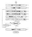
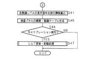
次に、キャリブレーション処理について説明する。図7及び図8は本発明の液晶表示装置1の輝度測定方法のキャリブレーション処理の手順を示すフローチャートである。CPU2は、内蔵光センサ駆動回路7を制御して、内蔵光センサ12をベゼル部から表示面14aへ移動する(S31)。CPU2は、バックライト電源回路9を制御して、バックライト13の光量を調整し、表示面14aのブライトネスを所望のブライトネス(例えば、ユーザが操作部8で設定したブライトネス)に設定する(S32)。 Next, the calibration process will be described. 7 and 8 are flowcharts showing the procedure of the calibration process of the luminance measuring method of the liquid
CPU2は、液晶駆動回路10を制御して、入力階調(階調レベル)iを0に設定し(S33)、内蔵光センサ12で表示面14aの周辺部の輝度LPiを測定し(S34)、測定した輝度LPiを記憶する(S35)。CPU2は、すべての階調(例えば、階調レベルが0〜256)に対して輝度が測定されたか否かを判定し(S36)、すべての階調で測定されていない場合(S36でNO)、入力階調iに1を加算して(S37)、ステップS34以降の処理を続ける。The
すべての階調で輝度が測定された場合(S36でYES)、CPU2は、入力階調が255における表示面14aの輝度、すなわち、キャリブレーション時のブライトネスを測定する(S38)。CPU2は、測定したブライトネス(測定値)が推奨ブライトネス(推奨値)の105%より大きいか否かを判定し(S39)、測定値が推奨値の105%より大きくない場合(S39でNO)、測定値が推奨値の95%より小さいか否かを判定する(S40)。 When the luminance is measured at all gradations (YES in S36), the
測定値が推奨値の95%より小さくない場合(S40でNO)、CPU2は、各階調毎に測定された表示面14aの周辺部の輝度と、階調補正テーブルとに基づいて、各階調レベルの表示面14aの中央部の輝度を算出する(S41)。 When the measured value is not smaller than 95% of the recommended value (NO in S40), the
測定値が推奨値の105%より大きい場合(S39でYES)、CPU2は、推奨ブライトネス時の輝度の相対比LGC255/LPC255、及び高ブライトネス時の輝度の相対比LGH/LPHを線形補間して、キャリブレーション時のブライトネスにおける輝度の相対比LG/LPを算出し(S42)、推奨ブライトネス時の輝度の相対比LGC255/LPC255とキャリブレーション時のブライトネスにおける輝度の相対比LG/LPとの差分に応じた補正係数α1に基づいて、階調補正テーブル5eを更新し(S43)、ステップS41以降の処理を続ける。When the measured value is larger than 105% of the recommended value (YES in S39), the
測定値が推奨値の95%より小さい場合(S40でYES)、CPU2は、推奨ブライトネス時の輝度の相対比LGC255/LPC255、及び低ブライトネス時の輝度の相対比LGL/LPLを線形補間して、キャリブレーション時のブライトネスにおける輝度の相対比LG/LPを算出し(S44)、推奨ブライトネス時の輝度の相対比LGC255/LPC255とキャリブレーション時のブライトネスにおける輝度の相対比LG/LPとの差分に応じた補正係数α2に基づいて、階調補正テーブル5eを更新し(S43)、ステップS41以降の処理を続ける。When the measured value is smaller than 95% of the recommended value (YES in S40), the
CPU2は、ステップS41で算出した輝度値に基づいて、液晶パネル14の輝度階調テーブル5fを生成し(S45)、キャリブレーション実行キーが操作されたか否かに基づいて、キャリブレーションを実行するか否かを判定する(S46)。キャリブレーションを実行する場合(S46でYES)、CPU2は、LUT更新・記憶処理を行い(S47)、処理を終了する。キャリブレーションを実行しない場合(S46でNO)、CPU2は、処理を終了する。 The
図9はLUT更新・記憶処理の手順を示すフローチャートである。CPU2は、理想階調特性テーブル5aに基づいた理想階調特性値Tkと、輝度階調テーブル5fに基づいた液晶パネル階調特性値Ljとの差分値(Tk−Lj)を算出する(S461)。ここでk及びjは、0から255までの整数値である。 FIG. 9 is a flowchart showing a procedure of LUT update / storage processing. The
CPU2は、差分値の絶対値|Tk−Lj|が最小となる階調レベルk、入力レベルjの組合せを抽出し(S462)、抽出した階調レベルkをインデックス値とし、入力レベルjをバリュー値として記憶し(S463)、処理を終了する。これにより、入力された映像信号により表現される階調レベルと、その階調レベルに対応する液晶パネルへの入力レベルとが関連付けられたLUT5bを更新して記憶する。 The
図10はキャリブレーション時のブライトネスが推奨ブライトネスの105%より大きい場合の輝度の相対比LG/LPを算出する一例を示すグラフであり、図11はキャリブレーション時のブライトネスが推奨ブライトネスの95%より小さい場合の輝度の相対比LG/LPを算出する一例を示すグラフである。図において、横軸はブライトネスを表し、縦軸は輝度の相対比を表す。 FIG. 10 is a graph showing an example of calculating the relative luminance ratio LG / LP when the brightness at the time of calibration is larger than 105% of the recommended brightness. FIG. 11 is a graph showing the brightness at the time of calibration of 95% of the recommended brightness. It is a graph which shows an example which calculates the relative ratio LG / LP of the brightness | luminance in the case of being small. In the figure, the horizontal axis represents brightness, and the vertical axis represents the relative ratio of luminance.
図10に示すように、キャリブレーション時のブライトネスが推奨ブライトネスの105%より大きい場合は、高ブライトネス時の輝度LPHと推奨ブライトネス時の輝度LPC255との差分x1と、高ブライトネス時の輝度の相対比LGH/LPHと推奨ブライトネス時の輝度の相対比LGC255/LPC255との差分y1との比に基づいて、キャリブレーション時の輝度LPと推奨ブライトネス時の輝度LPC255との差分Δx1から、キャリブレーション時の輝度の相対比LG/LPと推奨ブライトネス時の輝度の相対比LGC255/LPC255との差分Δy1を算出(線形補間)し、算出したΔy1に推奨ブライトネス時の輝度の相対比LGC255/LPC255を加算することにより、キャリブレーション時の輝度の相対比LG/LPを算出する。As shown in FIG. 10, when the brightness at the time of calibration is larger than 105% of the recommended brightness, the difference x1 between the brightness LPH at the high brightness and the brightness LPC255 at the recommended brightness and the relative brightness of the brightness at the high brightness. based on the ratio of the difference y1 between the relative ratio LGC255 / LPC255 of luminance in the ratio LGH / LPH and recommended brightness, the difference Δx1 between the luminance LPC255 when luminance LP and recommendations brightness during calibration, calibration The difference Δy1 between the relative luminance ratio LG / LP at the brightness and the relative brightness ratio LGC255 / LPC255 at the recommended brightness is calculated (linear interpolation), and the relative brightness ratio LGC255 at the recommended brightness is calculated as Δy1. / by adding the LPC255, to calculate the relative ratio LG / LP of luminance during calibration .
また、図11に示すように、キャリブレーション時のブライトネスが推奨ブライトネスの95%より小さい場合は、低ブライトネス時の輝度LPLと推奨ブライトネス時の輝度LPC255との差分x2と、低ブライトネス時の輝度の相対比LGL/LPLと推奨ブライトネス時の輝度の相対比LGC255/LPC255との差分y2との比に基づいて、キャリブレーション時の輝度LPと推奨ブライトネス時の輝度LPC255との差分Δx2から、キャリブレーション時の輝度の相対比LG/LPと推奨ブライトネス時の輝度の相対比LGC255/LPC255との差分Δy2を算出(線形補間)し、推奨ブライトネス時の輝度の相対比LGC255/LPC255から算出したΔy2を減算することにより、キャリブレーション時の輝度の相対比LG/LPを算出する。As shown in FIG. 11, when the brightness at the time of calibration is smaller than 95% of the recommended brightness, the difference x2 between the brightness LPL at the low brightness and the brightness LPC255 at the recommended brightness, and the brightness at the low brightness. From the difference Δx2 between the luminance LP during calibration and the luminance LPC255 during recommended brightness based on the ratio y2 between the relative ratio LGL / LPL and the relative luminance ratio LGC255 / LPC255 during recommended brightness The difference Δy2 between the relative luminance ratio LG / LP at the time of calibration and the relative luminance ratio LGC255 / LPC255 at the recommended brightness is calculated (linear interpolation), and the relative luminance ratio LGC255 / LPC at the recommended brightness is calculated. by subtracting the Δy2 calculated from255, the relative ratio LG / LP of luminance during calibration Out to.
図12は階調補正テーブル5eの更新例を示すグラフである。図において、横軸は階調レベルを表し、縦軸は輝度の相対比を表す。キャリブレーション時のブライトネスが推奨ブライトネス(推奨値)に近い場合(例えば、推奨値の±5%以内である場合)、階調補正テーブル5eは更新されず、コレレーション処理において測定された推奨ブライトネスにおける階調補正テーブル(図において破線のグラフ)を使用してLUT更新・記憶処理を行う。 FIG. 12 is a graph showing an example of updating the gradation correction table 5e. In the figure, the horizontal axis represents the gradation level, and the vertical axis represents the relative luminance ratio. When the brightness at the time of calibration is close to the recommended brightness (recommended value) (for example, within ± 5% of the recommended value), the gradation correction table 5e is not updated, and the recommended brightness measured in the correlation process is not updated. LUT update / storage processing is performed using a gradation correction table (broken line graph in the figure).
キャリブレーション時のブライトネスが推奨ブライトネス(推奨値)より大きい場合(例えば、推奨値の105%より大きい場合)、推奨ブライトネス時の輝度の相対比LGC255/LPC255とキャリブレーション時のブライトネスにおける輝度の相対比LG/LPとの差分に応じた補正係数α1に基づいて、コレレーション処理において測定された推奨ブライトネスにおける階調補正テーブル(図において破線のグラフで示される)を上方に並行移動した階調補正テーブル(図において実線Aのグラフで示される)に更新してLUT更新・記憶処理を行う。If the brightness at calibration is greater than the recommended brightness (recommended value) (for example, greater than 105% of the recommended value), the relative brightness ratio LGC255 / LPC255 at the recommended brightness and the brightness at the calibration brightness A gradation obtained by moving the gradation correction table (indicated by a broken line in the figure) in the recommended brightness measured in the correlation process upward in parallel based on the correction coefficient α1 corresponding to the difference from the relative ratio LG / LP. Update to the correction table (indicated by the solid line A graph in the figure) and perform LUT update / storage processing.
また、キャリブレーション時のブライトネスが推奨ブライトネス(推奨値)より小さい場合(例えば、推奨値の95%より小さい場合)、推奨ブライトネス時の輝度の相対比LGC255/LPC255とキャリブレーション時のブライトネスにおける輝度の相対比LG/LPとの差分に応じた補正係数α2に基づいて、コレレーション処理において測定された推奨ブライトネスにおける階調補正テーブル(図において破線のグラフで示される)を下方に並行移動した階調補正テーブル(図において実線Bのグラフで示される)に更新してLUT更新・記憶処理を行う。In addition, when the brightness at the time of calibration is smaller than the recommended brightness (recommended value) (for example, less than 95% of the recommended value), the relative brightness ratio LGC255 / LPC255 at the recommended brightness and the brightness at the time of calibration Based on the correction coefficient α2 corresponding to the difference from the luminance relative ratio LG / LP, the gradation correction table (represented by a broken line in the figure) in the recommended brightness measured in the correlation process is moved downward in parallel. Update the tone correction table (indicated by the solid line B in the figure) and perform LUT update / storage processing.
図13はLUT5bの内容の一例を示す概念図である。LUT5bは、インデックス値としての階調レベルと、バリュー値としての入力レベルとを互いに関連付けて記憶してある。なお、階調レベルの階調数、入力レベル数は、いずれも8ビット(256)の場合を示しているが、これに限定されるものではない。図に示すように、LUT5bは、階調レベル「0」と入力レベル「0」とが、階調レベル「1」と入力レベル「2」とが、階調レベル「2」と入力レベル「3」とが、…、階調レベル「255」と入力レベル「255」とが、関連付けられている。従って、液晶表示装置1は、入力された画素の階調レベルが「1」である場合、LUT5bに基づいて、その階調レベルと関連付けられた入力レベル「2」に変換して出力する。 FIG. 13 is a conceptual diagram showing an example of the contents of the
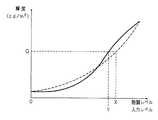
図14はLUT5bを用いた輝度調整の概念を示す説明図である。図において、横軸は階調レベル又は入力レベルを表し、縦軸は輝度を表す。実線は液晶パネル14の実際の階調特性を示し、破線は設定すべき理想的な階調特性を示す。液晶表示装置1は、入力した映像信号により表現される階調レベルXを、LUT5bに基づいて、液晶パネル14への入力レベルYに変換し、理想的な階調特性を得る輝度Qとなるようにして所要の理想階調特性を実現する。これにより、経年変化、階調レベルの大小、及び設定された所望のブライトネスの高低に拘わらず、キャリブレーションの都度、所要の理想階調特性を得ることができる。 FIG. 14 is an explanatory diagram showing the concept of brightness adjustment using the
以上説明したように、本発明にあっては、液晶パネル14の表示面14aの中央部の輝度と周辺部の輝度との相対比を予め記憶しておき、表示面14aの周辺部の輝度を検出し、検出した周辺部の輝度と予め記憶してある相対比とに基づいて、表示面14aの中央部の輝度を算出する。液晶パネル14の階調特性を調整(キャリブレーション)する場合は、算出された輝度に基づいて、液晶パネル14の輝度を所要の輝度に調整することにより、キャリブレーションの都度、液晶パネル14の表示面14aの中央部に光センサを当てるという手作業を行う必要がなく、ユーザの作業負荷が軽減され、ユーザの利便性が向上する。また、表示面14aの輝度に基づいて階調特性を補正することができるので、液晶パネル14を介してバックライト13の経年変化を検出することができ、バックライト13及び液晶パネル14に経年変化がある場合であっても、経年変化に応じた輝度のずれを補正して所要の階調特性を得ることができる。また、液晶パネル14の階調特性を調整(キャリブレーション)しない場合であっても、算出された輝度に基づいて、表示面14aの表示が正常であるか否かを判断することができる。 As described above, in the present invention, the relative ratio between the luminance of the central portion of the display surface 14a of the
また、液晶パネル14の表示面14aの中央部の輝度と周辺部の輝度との相対比を階調レベル0〜255の各階調レベル毎に予め記憶しておき、各階調レベル毎に表示面14aの周辺部の輝度を検出し、検出した周辺部の輝度と予め記憶してある相対比とに基づいて、各階調レベルにおいて、表示面14aの中央部の輝度を算出する。キャリブレーションをする場合は、算出された輝度に基づいて、液晶パネル14の輝度を所要の輝度に調整することにより、いずれの階調レベルにおいても、液晶パネル14の表示面14aの中央部の輝度を算出することができ、階調レベルの大小にかかわらず、所要の階調特性を得ることができ、階調レベルの影響を受けずに精度良くキャリブレーションを行うことができる。また、キャリブレーションをしない場合であっても、階調レベルの大小にかかわらず、算出された輝度に基づいて、表示面14aの表示が正常であるか否かを判断することができる。 Further, the relative ratio between the luminance of the central portion of the display surface 14a of the
また、液晶パネル14の表示面14aの中央部の輝度と周辺部の輝度との相対比を、例えば、推奨ブライトネス、高ブライトネス、低ブライトネス毎に予め記憶しておき、ユーザの所望のブライトネスに設定し、表示面14aの周辺部の輝度を検出し、検出した周辺部の輝度と線形補間された相対比とに基づいて、設定された所望のブライトネスにおける表示面14aの中央部の輝度を算出する。キャリブレーションをする場合は、算出された輝度に基づいて、液晶パネル14の輝度を所要の輝度に調整することにより、ブライトネスの高低にかかわらず、所要の階調特性を実現でき、ユーザがいかなるブライトネスで使用した場合であっても、ブライトネスの影響を受けずに精度良くキャリブレーションを行うことができる。また、キャリブレーションをしない場合であっても、ブライトネスの高低に拘わらず、表示面14aの表示が正常であるか否かを判断することができる。 In addition, the relative ratio between the luminance of the central portion of the display surface 14a of the
また、コレレーション処理を行う場合に、予め校正された外部光センサ16により、表示面14aの中央部の輝度測定を行うことで、表示面14aの周辺部の輝度測定のための内蔵光センサ12の擬似的な校正が可能となる。その結果、表示面14aの周辺部の輝度測定を行う内蔵光センサ12の校正を行うために、液晶表示装置から内蔵光センサ12を取り外すという煩雑な作業を解消することができる。 Further, when performing the correlation process, the built-in
上述の実施の形態では、輝度調整に用いるLUTを1つとし、主としてモノクロ液晶表示装置に好適な形態を示したが、モノクロ液晶表示装置に限定されるものではなく、カラー液晶表示装置にも、本発明を適用することができる。この場合、液晶物質における光の透過率は光の波長によって異なるため、輝度調整用に用いるLUTを各色(RGB)の用意することにより、精度良く所要の色度特性を実現することができる。 In the above-described embodiment, one LUT is used for luminance adjustment, and a form suitable mainly for a monochrome liquid crystal display device is shown. However, the present invention is not limited to a monochrome liquid crystal display device, The present invention can be applied. In this case, since the light transmittance in the liquid crystal material varies depending on the wavelength of light, the required chromaticity characteristics can be realized with high accuracy by preparing each color (RGB) as an LUT used for luminance adjustment.
上述の実施の形態においては、液晶表示装置1は、制御用のCPU2を内蔵する構成であったが、これに限定されるものではなく、例えば、CPU2、ROM3、RAM4、記憶部5などを別個のPCに組み込み、バックライト13、液晶パネル14などを備えたモニタ本体と分離して構成することも可能である。 In the above-described embodiment, the liquid
上述の実施の形態においては、キャリブレーション処理を操作部8の操作で行う形態を示したが、これに限定されない。例えば、複数の液晶表示装置1を所要の箇所に設置しておき、各液晶表示装置1は、LANなどの通信回線を介してサーバ装置に接続する。サーバ装置からキャリブレーション処理実行命令を各液晶表示装置1へ送信し、キャリブレーション処理実行命令を受信した液晶表示装置1は、夫々キャリブレーション処理を行う構成であってもよい。これにより、例えば、病院などに多数設置される医療用の液晶表示装置などを、キャリブレーションの都度、ユーザの手を煩わせることなく、容易にキャリブレーションを行うことが可能となる。 In the above-mentioned embodiment, although the form which performs a calibration process by operation of the
また、予め液晶表示装置、又は液晶表示装置に接続された外部のサーバなどで、表示面の輝度を測定するスケジューリング(例えば、電源投入時、24時間おき、1週間おき、1月おき、などユーザの要望に対応できるような測定計画)を記憶しておき、所定の時点で輝度の測定を自動で実行するようにしてもよい。この場合、測定した輝度値に基づいて、表示面が正常であるか否かを判断でき、異常がある場合には、ユーザに通知することもできる。これにより、ユーザが、例えば、多数の液晶表示装置を使用している場合に、1台毎に輝度を測定する労力を軽減することができる。また、測定した輝度が異常である場合、自動的にキャリブレーションを実行するようにすることもできる。これにより、ユーザによるキャリブレーション実行の操作がなくても、常に表示面の輝度を所要の値に保持することが可能となる。 In addition, a schedule for measuring the brightness of the display screen on a liquid crystal display device or an external server connected to the liquid crystal display device in advance (for example, when power is turned on, every 24 hours, every week, every month, etc.) (Measurement plan capable of responding to the request) is stored, and the luminance measurement may be automatically executed at a predetermined time point. In this case, based on the measured luminance value, it can be determined whether or not the display surface is normal, and if there is an abnormality, the user can be notified. Thereby, when a user uses many liquid crystal display devices, for example, the labor which measures a brightness | luminance for every 1 unit | set can be reduced. In addition, when the measured luminance is abnormal, calibration can be automatically executed. Thereby, it is possible to always maintain the brightness of the display surface at a required value even if the user does not perform calibration operation.
上述の実施の形態においては、液晶パネル14の表示面14aの中央部と周辺部の輝度の相対比を用いるものであったが、これに限定されるものではなく、例えば、表示面14aの周辺部と中央部の輝度の相対差でもよく、表示面14aの中央部と周辺部の輝度の差など、中央部と周辺部との間の輝度差を関連付けることができる関連値であれば、どのようなものを用いてもよい。 In the above-described embodiment, the relative ratio of the luminance between the central portion and the peripheral portion of the display surface 14a of the
上述の実施の形態においては、階調値の総数である階調数が256の場合について説明したが、階調数は、これに限定されるものではなく、他の階調数を用いることもできる。 In the above-described embodiment, the case where the number of gradations which is the total number of gradation values is 256 has been described. However, the number of gradations is not limited to this, and other gradation numbers may be used. it can.
上述の実施の形態においては、コレレーション時に、予め0〜255の階調レベル毎に表示面14aの中央部及び周辺部の輝度を測定しておき、キャリブレーション時にも、0〜255の階調レベル毎に表示面14aの周辺部の輝度を測定する構成であったが、これに限定されるものではなく、キャリブレーション時に輝度を検出する場合、0〜255の階調レベルの中から、間引きして階調レベルを設定して、輝度を検出する構成であってもよい。この場合、キャリブレーション処理に要する処理負担を軽減することができる。 In the above-described embodiment, the luminance of the central portion and the peripheral portion of the display surface 14a is measured in advance for each gradation level of 0 to 255 at the time of correlation, and the gradation of 0 to 255 is also obtained during calibration. The brightness of the peripheral portion of the display surface 14a is measured for each level. However, the present invention is not limited to this. When the brightness is detected during calibration, thinning is performed from 0 to 255 gradation levels. Thus, the luminance level may be detected by setting the gradation level. In this case, the processing burden required for the calibration process can be reduced.
上述の実施の形態においては、高ブライトネス、推奨ブライトネス、及び低ブライトネスの3つのブライトネスに対してコレレーション処理を行う構成であったが、コレレーション処理時に使用するブライトネスの数は、これに限定されるものではない。例えば、すべてのブライトネス毎に、コレレーション処理を行う構成であってもよい。これにより、測定したブライトネスと推奨値との比較処理を行う必要がなくなり、より高精度のキャリブレーションが可能となる。 In the above-described embodiment, the correlation processing is performed for three brightnesses of high brightness, recommended brightness, and low brightness. However, the number of brightnesses used in the correlation processing is limited to this. It is not something. For example, a configuration in which a correlation process is performed for every brightness is also possible. As a result, it is not necessary to perform a comparison process between the measured brightness and the recommended value, and calibration with higher accuracy is possible.
上述の実施の形態においては、キャリブレーション時に設定されるブライトネスと推奨ブライトネスとの比較で、推奨値の±5%を用いる場合を説明したが、これに限定されるものではない。 In the above-described embodiment, the case where ± 5% of the recommended value is used in the comparison between the brightness set at the time of calibration and the recommended brightness has been described. However, the present invention is not limited to this.
表示面の周辺部の輝度測定は、内蔵光センサではなく、ベゼル部に装着可能な外付け光センサであってもよい。これにより、内蔵光センサを装備していない既存の液晶表示装置に対しても本発明を適用することが可能となる。 The brightness measurement of the peripheral part of the display surface may be an external optical sensor that can be attached to the bezel instead of the built-in optical sensor. This makes it possible to apply the present invention to an existing liquid crystal display device that is not equipped with a built-in optical sensor.
2 CPU
3 ROM
4 RAM
5 記憶部
6 信号入力部
7 内蔵光センサ駆動回路
8 操作部
9 バックライト電源回路
10 液晶駆動回路
11 DCモータ
12 内蔵光センサ
13 バックライト
14 液晶パネル
16 外部光センサ2 CPU
3 ROM
4 RAM
DESCRIPTION OF
Claims (12)
Translated fromJapanese前記表示面の中央部及び周辺部の輝度差を関連付ける関連値を予め記憶する手段と、
前記表示面の周辺部の輝度を検出する検出手段と、
検出された輝度及び前記関連値に基づいて、前記表示面の中央部の輝度を算出する算出手段と
を備えることを特徴とする液晶表示装置。In a liquid crystal display device comprising a liquid crystal panel and a backlight, and displaying an image on the display surface of the liquid crystal panel using the backlight as a light source,
Means for storing in advance a related value for associating a luminance difference between a central portion and a peripheral portion of the display surface;
Detecting means for detecting a luminance of a peripheral portion of the display surface;
A liquid crystal display device comprising: calculating means for calculating the luminance of the central portion of the display surface based on the detected luminance and the related value.
前記関連値を複数の階調値毎に予め記憶する手段と
を備え、
前記検出手段は、
設定された複数の階調値毎に前記表示面の周辺部の輝度を検出するようにしてあり、
前記算出手段は、
検出された輝度及び前記関連値に基づいて、前記表示面の略中央部の輝度を前記複数の階調値毎に算出するようにしてあることを特徴とする請求項1に記載の液晶表示装置。Means for setting a gradation value representing the level of brightness;
Means for storing the related value in advance for each of a plurality of gradation values;
The detection means includes
The brightness of the peripheral portion of the display surface is detected for each of a plurality of set gradation values,
The calculating means includes
2. The liquid crystal display device according to claim 1, wherein a luminance at a substantially central portion of the display surface is calculated for each of the plurality of gradation values based on the detected luminance and the related value. .
前記関連値をバックライトの光量毎に予め複数記憶する手段と
を備え、
前記検出手段は、
設定されたバックライトの光量毎に前記表示面の周辺部の輝度を検出するようにしてあり、
前記算出手段は、
検出された輝度及び前記関連値に基づいて、設定されたバックライトの光量に対する前記表示面の中央部の輝度を算出するようにしてあることを特徴とする請求項1又は請求項2に記載の液晶表示装置。Means for setting the amount of backlight;
Means for storing a plurality of the related values in advance for each light quantity of the backlight,
The detection means includes
The brightness of the peripheral portion of the display surface is detected for each light amount of the set backlight,
The calculating means includes
The brightness of the central part of the display surface with respect to the set light amount of the backlight is calculated based on the detected brightness and the related value. Liquid crystal display device.
前記表示面の中央部及び周辺部の輝度差を関連付ける関連値を予め記憶し、
前記表示面の周辺部の輝度を検出し、
検出された輝度及び前記関連値に基づいて、前記表示面の中央部の輝度を算出することを特徴とする輝度測定方法。In a luminance measurement method of a liquid crystal display device comprising a liquid crystal panel and a backlight, and displaying an image on the display surface of the liquid crystal panel using the backlight as a light source,
A related value that associates a luminance difference between a central portion and a peripheral portion of the display surface is stored in advance,
Detecting the brightness of the periphery of the display surface;
A luminance measurement method, comprising: calculating a luminance of a central portion of the display surface based on the detected luminance and the related value.
階調値を複数設定し、
設定された複数の階調値毎に前記表示面の周辺部の輝度を検出し、
検出された輝度及び前記関連値に基づいて、前記表示面の中央部の輝度を前記複数の階調値毎に算出することを特徴とする請求項5に記載の輝度測定方法。A plurality of the related values are stored in advance for each gradation value representing the level of brightness,
Set multiple gradation values,
Detecting the brightness of the periphery of the display surface for each of a plurality of set gradation values;
6. The luminance measuring method according to claim 5, wherein the luminance of the central portion of the display surface is calculated for each of the plurality of gradation values based on the detected luminance and the related value.
バックライトの光量を設定し、
設定されたバックライトの光量毎に前記表示面の周辺部の輝度を検出し、
検出された輝度及び前記関連値に基づいて、設定されたバックライトの光量に対する前記表示面の中央部の輝度を算出することを特徴とする請求項5又は請求項6に記載の輝度測定方法。A plurality of the related values are stored in advance for each light amount of the backlight,
Set the amount of backlight,
Detect the brightness of the periphery of the display surface for each set backlight amount,
The luminance measurement method according to claim 5 or 6, wherein a luminance of a central portion of the display surface with respect to a set amount of backlight is calculated based on the detected luminance and the related value.
コンピュータを、
前記表示面の周辺部の輝度を光センサで測定する手段、並びに、
測定された前記表示面の周辺部の輝度並びに前記表示面の中央部及び周辺部の輝度差を関連付ける関連値に基づいて、前記表示面の中央部の輝度を算出する算出手段
として機能させることを特徴とするコンピュータプログラム。In a computer program for causing a computerto calculate the luminance of a display surface of a liquid crystal panel included in a liquid crystal display device,
Computer
Means for measuring the luminance of the peripheral portion of the display surface with an optical sensor, and
Based on the measured luminance of the peripheral portion of the display surface and a related value that correlates the luminance difference between the central portion of the display surface and the peripheral portion, the calculation means for calculating the luminance of the central portion of the display surface. A featured computer program.
前記表示面の輝度の高低度合いを表す複数の階調値を設定する手段、
設定された複数の階調値毎に前記表示面の周辺部の輝度を光センサで測定する手段、並びに、
測定された輝度及び、予め記憶されてある複数の階調値毎の前記関連値に基づいて、前記表示面の中央部の輝度を設定された複数の階調値毎に算出する手段
として機能させることを特徴とする請求項9に記載のコンピュータプログラム。Computer
It means to set aplurality of gradation values representing the high and low degree of brightnessof the displaysurface,
It means tomeasure a light sensor the brightness of the peripheral portion of the display surface in each set plurality of gradationvalues, and,
Based on the measured luminance andthe related valuestored for each ofa plurality of gradation valuesstored in advance, it functions as means for calculating the luminance of the central portion of the display surface for each of a plurality of set gradation values. The computer program according to claim 9.
バックライトの光量を設定する手段、
設定されたバックライトの光量の前記表示面の周辺部の輝度を光センサで測定する手段、並びに、
測定された輝度及び、予め記憶されてあるバックライトの光量毎の前記関連値に基づいて、設定されたバックライトの光量に対する前記表示面の中央部の輝度を算出する手段
として機能させることを特徴とする請求項9又は請求項10に記載のコンピュータプログラム。Computer
Means for setting the amount of light of the backlight,
It means tomeasure the luminance of the peripheral portion of the display surfaceof the light quantity of the set back-lightby the opticalsensors,and,
Based on the measured luminance andthe related valuestored for each light amount of the backlightstored in advance, it functions as means for calculating the luminance of the central portion of the display surface with respect to the light amount of the set backlight. The computer program according to claim 9 or 10.
算出された輝度に基づいて前記表示面の輝度を調整する調整手段として機能させることを特徴とする請求項9乃至請求項11のいずれかに記載のコンピュータプログラム。
Computer
12. The computer program according to claim 9, wherein the computer program functions as an adjustment unit that adjusts the luminance of the display surface based on the calculated luminance.
Priority Applications (1)
| Application Number | Priority Date | Filing Date | Title |
|---|---|---|---|
| JP2005221293AJP4393433B2 (en) | 2005-07-29 | 2005-07-29 | Liquid crystal display device, luminance measurement method, and computer program |
Applications Claiming Priority (1)
| Application Number | Priority Date | Filing Date | Title |
|---|---|---|---|
| JP2005221293AJP4393433B2 (en) | 2005-07-29 | 2005-07-29 | Liquid crystal display device, luminance measurement method, and computer program |
Publications (2)
| Publication Number | Publication Date |
|---|---|
| JP2007034209A JP2007034209A (en) | 2007-02-08 |
| JP4393433B2true JP4393433B2 (en) | 2010-01-06 |
Family
ID=37793504
Family Applications (1)
| Application Number | Title | Priority Date | Filing Date |
|---|---|---|---|
| JP2005221293AExpired - Fee RelatedJP4393433B2 (en) | 2005-07-29 | 2005-07-29 | Liquid crystal display device, luminance measurement method, and computer program |
Country Status (1)
| Country | Link |
|---|---|
| JP (1) | JP4393433B2 (en) |
Cited By (1)
| Publication number | Priority date | Publication date | Assignee | Title |
|---|---|---|---|---|
| CN105023512A (en)* | 2015-07-23 | 2015-11-04 | 苏州佳世达电通有限公司 | Display device |
Families Citing this family (18)
| Publication number | Priority date | Publication date | Assignee | Title |
|---|---|---|---|---|
| JP2008261856A (en)* | 2007-04-11 | 2008-10-30 | Dooyang Systems Inc | Automatic transfer device and method for imaging device characteristic value measuring sensor part |
| US7884832B2 (en)* | 2007-04-13 | 2011-02-08 | Global Oled Technology Llc | Calibrating RGBW displays |
| JP5200547B2 (en) | 2008-01-10 | 2013-06-05 | コニカミノルタオプティクス株式会社 | Display color sensor, display system using the same, and display calibration method |
| JP5404071B2 (en)* | 2009-01-26 | 2014-01-29 | キヤノン株式会社 | Liquid crystal display |
| JP4809453B2 (en)* | 2009-04-15 | 2011-11-09 | 株式会社ナナオ | Display device, display system, and correction method |
| JP4734555B2 (en)* | 2009-07-14 | 2011-07-27 | 株式会社ナナオ | Sensor unit operating mechanism, optical measuring device, and image display device |
| JP5039104B2 (en)* | 2009-08-26 | 2012-10-03 | 株式会社ナナオ | Luminescence intensity measuring method, luminescence intensity measuring apparatus and computer program |
| JP4669558B1 (en)* | 2009-10-20 | 2011-04-13 | 株式会社ナナオ | Display device, computer program, recording medium, and image display method |
| JP5651419B2 (en)* | 2009-10-28 | 2015-01-14 | Eizo株式会社 | Correction method, display device, and computer program |
| JP5177584B2 (en)* | 2010-07-01 | 2013-04-03 | 株式会社ナナオ | Display device, luminance value measuring method of display device, and computer program |
| JP5773453B2 (en)* | 2010-11-30 | 2015-09-02 | Necディスプレイソリューションズ株式会社 | Display device and calibration method for display device |
| JP5279096B2 (en)* | 2010-12-15 | 2013-09-04 | Eizo株式会社 | Display intensity estimation method and computer program |
| JP5746875B2 (en)* | 2011-02-10 | 2015-07-08 | 株式会社トプコン | Optometry system |
| JP5972013B2 (en)* | 2011-06-30 | 2016-08-17 | キヤノン株式会社 | Display device and control method thereof |
| JP5911118B2 (en)* | 2012-04-18 | 2016-04-27 | Necディスプレイソリューションズ株式会社 | Display device and display correction method |
| JP5800946B2 (en) | 2013-05-10 | 2015-10-28 | キヤノン株式会社 | Image display apparatus and control method thereof |
| JP2014222323A (en) | 2013-05-14 | 2014-11-27 | キヤノン株式会社 | Image display device and control method of the same, calibration device and control method of the same, program, and recording medium |
| JP7054577B2 (en)* | 2017-11-20 | 2022-04-14 | シナプティクス インコーポレイテッド | Display driver, display device and unevenness correction method |
Family Cites Families (10)
| Publication number | Priority date | Publication date | Assignee | Title |
|---|---|---|---|---|
| JPS61198196A (en)* | 1985-02-28 | 1986-09-02 | キヤノン株式会社 | Display unit |
| US5371537A (en)* | 1991-10-31 | 1994-12-06 | Eastman Kodak Company | Method and apparatus for automatically calibrating a CRT display |
| JPH0729526U (en)* | 1993-10-26 | 1995-06-02 | 株式会社デジタル | Liquid crystal display |
| JP2002162937A (en)* | 2000-11-22 | 2002-06-07 | Totoku Electric Co Ltd | Method and apparatus for adjusting gradation of liquid crystal display device |
| JP2004021147A (en)* | 2002-06-20 | 2004-01-22 | Advanced Display Inc | Planar light source device, and liquid crystal display using the same |
| US7345669B2 (en)* | 2003-03-28 | 2008-03-18 | Eizo Nanao Corporation | Photometric device of liquid crystal display and liquid crystal display |
| WO2004097510A1 (en)* | 2003-04-28 | 2004-11-11 | Totoku Electric Co., Ltd. | Display device |
| US7952555B2 (en)* | 2003-11-19 | 2011-05-31 | Eizo Nanao Corporation | Luminance control method, liquid crystal display device and computer program |
| JP2005208548A (en)* | 2003-12-26 | 2005-08-04 | Nippon Chemicon Corp | Self-adjusting type display system, and self-adjusting type monitor apparatus, and self-adjusting method of display system, and self-adjusting program |
| JP2006267789A (en)* | 2005-03-25 | 2006-10-05 | Matsushita Electric Ind Co Ltd | display |
- 2005
- 2005-07-29JPJP2005221293Apatent/JP4393433B2/ennot_activeExpired - Fee Related
Cited By (2)
| Publication number | Priority date | Publication date | Assignee | Title |
|---|---|---|---|---|
| CN105023512A (en)* | 2015-07-23 | 2015-11-04 | 苏州佳世达电通有限公司 | Display device |
| CN105023512B (en)* | 2015-07-23 | 2018-08-24 | 苏州佳世达电通有限公司 | Show equipment |
Also Published As
| Publication number | Publication date |
|---|---|
| JP2007034209A (en) | 2007-02-08 |
Similar Documents
| Publication | Publication Date | Title |
|---|---|---|
| JP4393433B2 (en) | Liquid crystal display device, luminance measurement method, and computer program | |
| JP3974630B2 (en) | Brightness adjustment method, liquid crystal display device, and computer program | |
| KR101399304B1 (en) | Liquid crystal display device and method of driving the same | |
| JP4870533B2 (en) | Gradation correction method for display device, display device, and computer program | |
| EP2367348B1 (en) | Method for generating a lookup table for color correction for an image display device | |
| US8872864B2 (en) | Display device, display system, and correction method | |
| JP4603747B2 (en) | Correction of edge effect and cell gap difference in tiled flat panel liquid crystal display | |
| CN102105104B (en) | Gray scale display device | |
| KR100885905B1 (en) | Image processing apparatus, image processing method, image output apparatus, image processing system | |
| US20060208983A1 (en) | Liquid crystal display and driving method thereof | |
| TWI405181B (en) | Calibration method for improving the uniformity of luminosity of display device and related device | |
| CN109246405B (en) | Method and system for adjusting uniformity of image tone | |
| JP5651419B2 (en) | Correction method, display device, and computer program | |
| US10965840B2 (en) | Display and color correction method | |
| CN101996612A (en) | Correction method for improving brightness uniformity of display device and related device | |
| JP4216800B2 (en) | Display method and display device | |
| JP4677399B2 (en) | Liquid crystal display device, characteristic amount measuring device for liquid crystal display device, characteristic amount measuring method, and computer program | |
| KR20170023615A (en) | Display Device Including Compensating Unit And Method Of Compensating Image Using The Same | |
| JP5177584B2 (en) | Display device, luminance value measuring method of display device, and computer program | |
| JP2008139430A (en) | Liquid crystal display device and driving method thereof | |
| JP2007178561A (en) | Display device and driving method thereof | |
| JP5039104B2 (en) | Luminescence intensity measuring method, luminescence intensity measuring apparatus and computer program | |
| JPH05249437A (en) | Display device | |
| JP2016075771A (en) | Video processing device, display device, program, recording medium | |
| KR100696684B1 (en) | LCD and its driving method |
Legal Events
| Date | Code | Title | Description |
|---|---|---|---|
| A977 | Report on retrieval | Free format text:JAPANESE INTERMEDIATE CODE: A971007 Effective date:20090612 | |
| A131 | Notification of reasons for refusal | Free format text:JAPANESE INTERMEDIATE CODE: A131 Effective date:20090623 | |
| RD13 | Notification of appointment of power of sub attorney | Free format text:JAPANESE INTERMEDIATE CODE: A7433 Effective date:20090722 | |
| A521 | Request for written amendment filed | Free format text:JAPANESE INTERMEDIATE CODE: A523 Effective date:20090806 | |
| A521 | Request for written amendment filed | Free format text:JAPANESE INTERMEDIATE CODE: A821 Effective date:20090722 | |
| TRDD | Decision of grant or rejection written | ||
| A01 | Written decision to grant a patent or to grant a registration (utility model) | Free format text:JAPANESE INTERMEDIATE CODE: A01 Effective date:20091006 | |
| A01 | Written decision to grant a patent or to grant a registration (utility model) | Free format text:JAPANESE INTERMEDIATE CODE: A01 | |
| A61 | First payment of annual fees (during grant procedure) | Free format text:JAPANESE INTERMEDIATE CODE: A61 Effective date:20091013 | |
| R150 | Certificate of patent or registration of utility model | Ref document number:4393433 Country of ref document:JP Free format text:JAPANESE INTERMEDIATE CODE: R150 Free format text:JAPANESE INTERMEDIATE CODE: R150 | |
| FPAY | Renewal fee payment (event date is renewal date of database) | Free format text:PAYMENT UNTIL: 20121023 Year of fee payment:3 | |
| FPAY | Renewal fee payment (event date is renewal date of database) | Free format text:PAYMENT UNTIL: 20121023 Year of fee payment:3 | |
| FPAY | Renewal fee payment (event date is renewal date of database) | Free format text:PAYMENT UNTIL: 20131023 Year of fee payment:4 | |
| R250 | Receipt of annual fees | Free format text:JAPANESE INTERMEDIATE CODE: R250 | |
| FPAY | Renewal fee payment (event date is renewal date of database) | Free format text:PAYMENT UNTIL: 20131023 Year of fee payment:4 | |
| S533 | Written request for registration of change of name | Free format text:JAPANESE INTERMEDIATE CODE: R313533 | |
| R350 | Written notification of registration of transfer | Free format text:JAPANESE INTERMEDIATE CODE: R350 | |
| R250 | Receipt of annual fees | Free format text:JAPANESE INTERMEDIATE CODE: R250 | |
| R250 | Receipt of annual fees | Free format text:JAPANESE INTERMEDIATE CODE: R250 | |
| R250 | Receipt of annual fees | Free format text:JAPANESE INTERMEDIATE CODE: R250 | |
| R250 | Receipt of annual fees | Free format text:JAPANESE INTERMEDIATE CODE: R250 | |
| R250 | Receipt of annual fees | Free format text:JAPANESE INTERMEDIATE CODE: R250 | |
| R250 | Receipt of annual fees | Free format text:JAPANESE INTERMEDIATE CODE: R250 | |
| R250 | Receipt of annual fees | Free format text:JAPANESE INTERMEDIATE CODE: R250 | |
| R250 | Receipt of annual fees | Free format text:JAPANESE INTERMEDIATE CODE: R250 | |
| R250 | Receipt of annual fees | Free format text:JAPANESE INTERMEDIATE CODE: R250 | |
| R250 | Receipt of annual fees | Free format text:JAPANESE INTERMEDIATE CODE: R250 | |
| R250 | Receipt of annual fees | Free format text:JAPANESE INTERMEDIATE CODE: R250 | |
| LAPS | Cancellation because of no payment of annual fees |