JP4393237B2 - Combined travel shift operating device - Google Patents
Combined travel shift operating deviceDownload PDFInfo
- Publication number
- JP4393237B2 JP4393237B2JP2004078628AJP2004078628AJP4393237B2JP 4393237 B2JP4393237 B2JP 4393237B2JP 2004078628 AJP2004078628 AJP 2004078628AJP 2004078628 AJP2004078628 AJP 2004078628AJP 4393237 B2JP4393237 B2JP 4393237B2
- Authority
- JP
- Japan
- Prior art keywords
- transmission
- sub
- shift
- main
- speed
- Prior art date
- Legal status (The legal status is an assumption and is not a legal conclusion. Google has not performed a legal analysis and makes no representation as to the accuracy of the status listed.)
- Expired - Fee Related
Links
Images


Landscapes
- Arrangement Or Mounting Of Control Devices For Change-Speed Gearing (AREA)
- Control Of Fluid Gearings (AREA)
- Gear-Shifting Mechanisms (AREA)
Description
Translated fromJapanese本発明は、エンジンから走行装置に動力伝達する伝動系に直列に設けた主変速装置と副変速装置を備えたコンバインの走行用変速操作装置に関する。TECHNICAL FIELD The present invention relates to acombined traveling speed change operation device including a main transmission device and a sub-transmission device provided in series with a transmission system for transmitting power from an engine to a traveling device.
コンバインにおいて、従来、たとえば特許文献1に示されるように、エンジンEからの動力を静油圧式の無段変速装置10を介してミッションケースMの走行伝動系に伝達するように構成し、無段変速装置10の出力軸13からの動力が第1軸S1の高速伝動ギヤ18とシフトギヤ19、第2軸S2の高速入力ギヤ20と中速入力ギヤ21と低速入力ギヤ22によって変速されるように副変速装置を構成し、無段変速装置10を変速操作する主変速レバー6、副変速装置を変速操作する副変速レバー7を備えたものがあった。
すなわち、主変速装置としての無段変速装置10を主変速レバー6によって変速操作し、副変速装置を副変速レバー7によって変速操作するように走行用変速操作装置を構成されたものがあった。Conventionally, the combine is configured to transmit the power from the engine E to the traveling transmission system of the transmission case M via the hydrostatic continuously
That is, there is a configuration in which a traveling speed change operation device is configured such that a continuously
また、たとえば特許文献2に示されるように、主変速装置Bを、第1,2,3,4油圧クラッチC1,C2,C3,C4の切り換えによって前進3段と後進2段に変速するように構成し、副変速装置Aを、油圧シリンダDによるクラッチスリーブ15のシフト操作によって高速伝動状態と低速伝動状態に変速するように構成し、第1,2,3,4油圧クラッチC1,C2,C3,C4、及び油圧シリンダDを操作する一つのロータリバルブVを備え、このロータリバルブVの回転スプールVSにピニオンギヤ27、セクタギヤ28を介して連動した変速レバー30を備え、変速レバー30によるロータリバルブVの切り換え操作によって副変速装置Aと主変速装置Bを制御して、副変速装置Aと主変速装置Bが所定の変速状態になった中立や伝動状態が現出されるようになったものがあった。
すなわち、変速レバー30を操作位置Nに操作すると、ロータリバルブVが中立位置Nになり、副変速装置A及び主変速装置Bが中立位置になった中立状態が現出される。変速レバー30を操作位置F1に操作すると、ロータリバルブVが前進1速F1の操作位置になり、副変速装置Aが低速伝動状態に、主変速装置Bが前進1速にそれぞれなった前進1速の変速状態が現出される。変速レバー30を操作位置F2に操作すると、ロータリバルブVが前進2速F2の操作位置になり、副変速装置Aが低速伝動状態に、主変速装置Bが前進2速にそれぞれなった前進2速の変速状態が現出される。変速レバー30を操作位置F3に操作すると、ロータリバルブVが前進3速F3の操作位置になり、副変速装置Aが低速伝動状態に、主変速装置Bが前進3速にそれぞれなった前進3速の変速状態が現出される。変速レバー30を操作位置F4に操作すると、ロータリバルブVが前進4速F4の操作位置になり、副変速装置Aが高速伝動状態に、主変速装置Bが前進1速にそれぞれなった前進4速の変速状態が現出される。変速レバー30を操作位置F5に操作すると、ロータリバルブVが前進5速F5の操作位置になり、副変速装置Aが高速伝動状態に、主変速装置Bが前進2速にそれぞれなった前進5速の変速状態が現出される。変速レバー30を操作位置F6に操作すると、ロータリバルブVが前進6速F6の操作位置になり、副変速装置Aが高速伝動状態に、主変速装置Bが前進3速にそれぞれなった前進6速の変速状態が現出されるものがあった。
つまり、主変速装置A及び副変速装置Bを一本の変速レバー30によって変速操作するように走行用変速操作装置を構成されたものがあった。For example, as shown in
That is, when the
That is, there is a configuration in which the traveling speed change operation device is configured such that the main speed change device A and the sub speed change device B are operated to be changed by a
たとえばコンバインにおいて、刈り取るべき穀稈に着粒や倒伏度合いなどの変化があれば、その変化にかかわらず引起しなどが適切な速度で行なわれるように走行速度を調節しながら作業されるが、主変速装置及び副変速装置をそれぞれ専用の操作手段によって変速操作する走行用変速操作装置を採用した場合、主変速装置を変速するための操作手間と、副変速装置を変速するための操作手間とを掛けるという煩わしさがあった。 For example, in a combine, if there is a change in the grain size or the level of lodging of the cereal to be harvested, the work is performed while adjusting the running speed so that the wake-up occurs at an appropriate speed regardless of the change. In the case of adopting a traveling speed change operation device for operating the speed change device and the sub-transmission device respectively with dedicated operation means, the operation time for shifting the main transmission device and the operation time for shifting the sub-transmission device are reduced. There was a hassle of hanging.
また、タンクに貯まった穀粒を降ろすなど、刈取り作業をしない走行、いわゆる移動走行を行なう際、刈取り作業を行なう場合よりも高速で変速しながら走行されるが、主変速装置及び副変速装置を1本の変速レバーによって変速操作する走行用変速操作装置を採用した場合、変速レバーの操作域の副変速装置が低速側になる部分と、副変速装置が高速側になる部分とから高速側部分を選択してこの高速側部分で変速レバーを操作する必要があり、変速レバーを操作するための操作域を選択するという煩わしさがあった。 Also, when running without cutting work, such as moving down the grain stored in the tank, so-called mobile running, it runs while shifting at a higher speed than when cutting, but the main transmission and sub-transmission are In the case of adopting a traveling speed change operation device that performs a speed change operation with one speed change lever, a portion of the speed change lever operating range from the portion where the sub-transmission device is on the low speed side and the portion where the sub-transmission device is on the high speed side to the high speed side portion And it is necessary to operate the speed change lever at this high speed side portion, and there is an annoyance of selecting an operation range for operating the speed change lever.
本発明の目的は、作業走行の際も移動走行の際もそれに応じた適切な変速走行を操作面などで有利に行なうことができるコンバインの走行用変速操作装置を提供することにある。SUMMARY OF THE INVENTION An object of the present invention is to provide acombined traveling speed change operation device capable of advantageously performing an appropriate speed change traveling according to the operation travel on the operation surface or the like during work travel and mobile travel.
本第1発明にあっては、エンジンから走行装置に動力伝達する伝動系に直列に設けた主変速装置と副変速装置を備えたコンバインの走行用変速操作装置であって、
前記主変速装置を変速操作する主変速レバーの操作位置を検出するレバー位置検出手段と、副変速指令を出力する副変速手段と、前記副変速装置を変速操作する副変速アクチュエータとを設け、前記主変速装置を前記主変速レバーの操作位置に対応する変速状態になるように操作し、かつ、前記レバー位置検出手段による検出情報に基づいて前記副変速装置が前記主変速レバーの操作位置に対応する変速状態に切り換えられるように前記副変速アクチュエータを操作する主副変速制御モードと、前記主変速装置を前記主変速レバーの操作位置に対応する変速状態になるように操作し、かつ、前記副変速手段からの副変速指令に基づいて前記副変速装置が前記副変速手段からの副変速指令に対応する変速状態に切り換えられて固定されるように前記レバー位置検出手段による検出情報に優先して前記副変速アクチュエータを操作する副変速制御モードとに切り換え自在な変速制御手段を設け、前記変速制御手段を前記主副変速制御モードと前記副変速制御モードとに切り換えるモード切り換え手段を設け、前記副変速手段が、移動走行用の高速副変速指令と、標準用の中速副変速指令と、倒伏の激しい穀稈を刈り取る倒伏用の低速副変速指令とを指令自在に構成され、前記副変速制御モードにおいて、前記副変速装置が、前記高速副変速指令に対応する所定の高速変速状態と、前記中速副変速指令に対応する所定の中速変速状態と、前記低速副変速指令に対応する所定の低速変速状態とに切り換えられるように構成されている。In the first aspect of the present invention, there is acombined traveling speed change operation device including a main transmission and an auxiliary transmission that are provided in series with a transmission system that transmits power from the engine to the traveling device,
A lever position detecting means for detecting an operation position of the main shift lever of the speed change operation of the main speed changedevice,and a subtransmission means for outputting the sub-shiftcommand,and an auxiliary transmission actuator for gear shift operation to the auxiliary speed change device isprovided, wherein It operates the main speed change device so as to shift state corresponding to the operating position of the main speed change lever, and,on the basis of the information detected by the lever position detector auxiliary transmission device corresponds to the operating position ofthe main speed change lever A main auxiliary transmission control mode for operating the auxiliary transmission actuator so asto beswitched to a transmission state tobe operated, the main transmissionis operated so as to be in a transmission state corresponding to an operation position of the main transmission lever, and asthe subtransmission deviceis fixed is switched to the corresponding shifting state to the sub speed change command fromthe subtransmission meansbased on the sub-shift command from the shift means In preference to the information detected by theserial lever position detecting means provided freely shift control means switchable between auxiliary transmission control mode for operating the auxiliary transmission actuator, the subtransmission controlling said shift control means and the main auxiliary shifting control mode Mode switching means for switching between modes is provided, and the sub-transmission means includes a high-speed sub-shift command for moving travel, a medium-speed sub-shift command for standard use, and a low-speed sub-shift command for lodging that harvests harsh fallen culms. And in the sub-shift control mode, the sub-transmission device has a predetermined high-speed shift state corresponding to the high-speed sub-shift command and a predetermined medium-speed shift corresponding to the medium-speed sub-shift command. And a predetermined low-speed shift state corresponding to the low-speed sub-shift command.
すなわち、モード切り換え手段によって変速制御手段を主副変速制御モードに切り換えると、主変速レバーを操作すれば、主変速レバーの操作のために主変速装置が主変速レバーの操作位置に対応する変速状態に操作され、この主変速装置の変速操作に併せ、変速制御手段がレバー位置検出手段による検出結果を基に副変速アクチュエータを操作して、副変速装置を主変速レバーの操作位置に対応する変速状態に操作する。これにより、主変速装置も副変速装置も主変速レバーの操作位置に対応する変速状態になる。 That is, when the shift control unit is switched to the main / sub shift control mode by the mode switching unit, the main transmission device can be operated in accordance with the operation position of the main shift lever for the operation of the main shift lever by operating the main shift lever. In conjunction with the speed change operation of the main transmission, the speed change control means operates the sub speed change actuator based on the detection result of the lever position detection means, so that the sub speed change gear corresponds to the operation position of the main speed change lever. Manipulate state. As a result, both the main transmission device and the sub-transmission device enter a shift state corresponding to the operation position of the main transmission lever.
モード切り換え手段によって変速制御手段を副変速制御モードに切り換えると、主変速レバーを操作すれば、主変速レバーの操作のために主変速装置が主変速レバーの操作位置に対応する変速状態に操作される。この場合、副変速手段を操作すれば、変速制御手段が副変速手段からの副変速指令を基に、レバー位置検出手段による検出結果に優先して副変速アクチュエータを操作して、副変速装置を副変速指令に対応する変速状態に操作する。これにより、主変速装置は、主変速レバーの操作位置に対応する変速状態になり、副変速装置は、主変速レバーによる主変速装置の変速操作とは無関係に、副変速指令に対応する変速状態になる。When switching the shift control means by the mode switching means to the sub speed change control mode, the main if the shift lever operation, the main speed change device for operation of the main shift lever isoperated to a shift state corresponding to the operating position of the main shift lever The In this case, if the auxiliary transmission means is operated, the transmission control means operates the auxiliary transmission actuator in preference to the detection result by the lever position detection means based on the auxiliary transmission command from the auxiliary transmission means, The shift operation corresponding to the sub shift command is performed. As a result, the main transmission is in a shift state corresponding to the operation position of the main shift lever, and the sub-transmission is in a shift state corresponding to the sub-shift command regardless of the shift operation of the main transmission by the main shift lever. become.
従って、本第1発明によれば、作業走行を行なうに当たり、変速制御手段を主副変速制御モードに切り換えることにより、主変速レバーを操作するだけで操作簡単に主変速装置も副変速装置も変速操作して作業が適切に行なえる走行速度を現出しながら作業することができる。また、作業を行なう際であっても、植立穀稈の倒伏が激しい場合など、変速制御手段を副変速制御モードに切り換え、副変速手段によって副変速装置を主変速装置とは無関係に単独で変速操作して低速側に固定しておき、副変速装置を高速側に切り換えて高速走行してしまうことがないように注意を払わなくとも楽に変速レバーを操作して、穀稈の状況に応じた適切な走行速度を現出しながら走行することができるなど、副変速装置を所定の変速状態に固定しながら主変速装置を所望の変速状態に変速操作して有利に作業することもできる。 Therefore, according to the first aspect of the present invention, when the work travel is performed, the shift control means is switched to the main / sub shift control mode, so that both the main transmission and the sub transmission can be shifted easily by operating the main shift lever. It is possible to work while displaying the running speed at which the work can be performed appropriately. In addition, even when working, when the planted cereals are prone to fall down, the transmission control means is switched to the auxiliary transmission control mode, and the auxiliary transmission is used independently of the main transmission by the auxiliary transmission means. Operate the shift lever and fix it on the low speed side, switch the auxiliary transmission to the high speed side and operate the shift lever easily without depending on the situation of the cereal so that it will not run at high speed It is also possible to work advantageously by shifting the main transmission to a desired shift state while fixing the auxiliary transmission to a predetermined shift state, such as being able to travel while displaying an appropriate travel speed.
移動走行を行なうに当たり、副変速手段によって副変速装置を主変速装置とは無関係に単独で変速操作して高速側に固定しておき、副変速装置を低速側に切り換えてしまうことがないように注意を払わなくとも楽に変速レバーを操作して、副変速装置を高速側に維持しながら変速走行することができる。 When carrying out traveling, the sub-transmission means does not change the sub-transmission device to the low-speed side by shifting the sub-transmission device independently of the main transmission and fixing it to the high-speed side. Even if care is not taken, the speed change lever can be operated easily, and the speed change drive can be performed while maintaining the auxiliary transmission on the high speed side.
本第2発明にあっては、本第1発明の構成において、前記モード切り換え手段を、主副変速モード選択手段と前記副変速手段とで構成し、前記主副変速モード選択手段によって主副変速モード指令を出力して前記変速制御手段を前記主副変速制御モードに切り換え操作し、前記副変速手段によって前記副変速指令と共に副変速モード指令を出力して前記変速制御手段を前記副変速制御モードに切り換え操作するように構成してある。This In the second aspect, in the structure of the present first invention, the mode switching means,constituted by the said auxiliary transmission section main subtransmission mode selectingmeans, main and sub transmission by the main sub-gear change mode selecting means outputs a mode command switching operating the shift control unit tothe main sub-shifting control mode, the subtransmission means bysaid auxiliary transmission command together with the subtransmissionthe said shift control means mode command output to the auxiliary transmission control mode It is configured to perform switching operation.
すなわち、副変速手段を操作すると、この副変速手段が副変速モード指令を出力するとともに副変速指令を出力し、変速制御手段が副変速モード指令に基づいて副変速制御モードに切り換わり、副変速アクチュエータを操作して副変速装置を副変速指令に対応する変速状態に切り換え操作する。これにより、副変速手段を操作すれば、主変速レバーによって主変速装置を副変速装置とは無関係に単独で変速操作することができるようになり、かつ、副変速装置を主変速装置とは無関係に単独で副変速指令に対応した変速状態に変速操作することができる。That is, when the sub-transmission unit is operated, the sub-transmission unit outputs a sub-transmission mode command and a sub-transmission command, and the shift control unit switches to the sub-transmission control modebased on the sub-transmission mode command. The actuator is operated to switch the auxiliary transmission to a shift state corresponding to the auxiliary transmission command. As a result, if the auxiliary transmission means is operated, the main transmission can be operated independently of the auxiliary transmission by the main transmission lever, and the auxiliary transmission is independent of the main transmission. In addition, it is possible to perform a shift operation independently to a shift state corresponding to the auxiliary shift command.
従って、本第2発明によれば、主変速レバーによって主変速装置も副変速装置も変速操作する状態から、副変速装置を所定の変速状態に固定しながら主変速レバーによって主変速装置を変速操作する状態に切り換えるに当たり、副変速装置を所定の変速状態に操作するための副変速指令を出力する副変速手段を操作するだけで操作簡単に切り換えることができる。 Therefore, according to the second aspect of the invention, from the state where the main transmission and the sub-transmission are shifted by the main shift lever, the main transmission is shifted by the main shift lever while fixing the sub-transmission to a predetermined shift state. When switching to the state to be performed, the operation can be easily switched only by operating the sub-transmission means for outputting the sub-transmission command for operating the sub-transmission device to the predetermined shift state.
本第3発明にあっては、本第1又は第2発明の構成において、前記主変速装置を静油圧式無段変速装置で構成して、前記静油圧式無段変速装置の油圧ポンプを操作することで前記主変速装置を変速操作するように構成し、前記副変速装置を前記静油圧式無段変速装置の油圧モータで構成し、前記油圧モータを、前記高速変速状態と、前記中速変速状態と、前記低速変速状態とに操作自在な可変容量形に構成してある。In the present third invention, in the configuration of the first or second invention,constitutethe main speed change device by the hydrostatic continuously variabletransmission, operates the hydraulic pump of the hydrostatic continuously variable transmission said main transmission configured to shift operations by, the auxiliary speed change deviceconstituted by a hydraulic motorofthe hydrostatic continuously variabletransmission, said hydraulic motor, and the high-speed shifting state, said medium speed The variable displacement type is configured to be freely operated between the speed change state and the low speed speed change state.
すなわち、副変速装置を所定の変速状態に固定しながら主変速レバーによって主変速装置を変速操作する変速形態を採用するに当たり、副変速装置を切り換え可能な複数の変速状態のいずれの変速状態に固定した場合でも、主変速レバーによって主変速装置を中立状態から高速側に変速操作していくことができる。そして、主変速装置を構成する静油圧式無段変速装置の油圧モータとして可変容量形の油圧モータを採用して副変速装置を構成するものである。 That is, when adopting a shift mode in which the main transmission is shifted by the main transmission lever while fixing the sub-transmission to a predetermined shift state, the sub-transmission is fixed to any one of a plurality of shift states that can be switched. Even in this case, the main transmission can be shifted from the neutral state to the high speed side by the main transmission lever. Then, a variable displacement hydraulic motor is adopted as the hydraulic motor of the hydrostatic continuously variable transmission that constitutes the main transmission to constitute the auxiliary transmission.
従って、本第3発明によれば、副変速装置を如何なる変速状態に固定する場合でも、主変速装置の変速操作を中立状態からスタートして機体走行を開始させることができる。しかも、主変速装置を構成する油圧モータを利用して副変速装置を構造簡単に構成して経済面で有利に得ることができる。 Therefore, according to the third aspect of the invention, regardless of the speed change state of the subtransmission, the speed change operation of the main transmission can be started from the neutral state to start the vehicle running. In addition, the sub-transmission can be constructed simply with the use of a hydraulic motor constituting the main transmission, which can be advantageously obtained economically.
本第4発明にあっては、本第1〜3発明のいずれか一つの発明の構成において、前記副変速手段として複数の副変速スイッチを設けるとともに、各副変速スイッチは、前記副変速装置を対応する変速状態に変速するべき副変速指令を出力するように構成してある。 According to the fourth aspect of the present invention, in the configuration of any one of the first to third aspects of the present invention, a plurality of auxiliary transmission switches are provided as the auxiliary transmission means, and each auxiliary transmission switch includes the auxiliary transmission device. A sub shift command to shift to the corresponding shift state is output.
すなわち、副変速スイッチから所定の副変速スイッチを選択して操作すれば、その副変速スイッチからの副変速指令を基に、変速制御手段が副変速アクチュエータを操作して副変速装置を操作された副変速スイッチに対応する変速状態に切り換え操作する。これにより、副変速手段として変速レバーを採用した場合、変速レバーを目標操作位置以上に操作してしまい、副変速装置を操作目標の変速状態と異なる変速状態に操作してしまうという誤操作が発生するが、この誤操作が発生しないようにしながら副変速操作が行なれるようにできる。 That is, if a predetermined sub-shift switch is selected and operated from the sub-shift switch, the shift control means operates the sub-shift actuator and operates the sub-transmission device based on the sub-shift command from the sub-shift switch. The operation is switched to the shift state corresponding to the sub-shift switch. As a result, when a shift lever is employed as the sub-transmission means, the shift lever is operated beyond the target operation position, and an erroneous operation occurs in which the sub-transmission device is operated in a shift state different from the operation target shift state. However, the sub-shift operation can be performed while preventing this erroneous operation from occurring.
従って、本第4発明によれば、副変速手段を過剰操作のない状態で操作させて副変速装置が所望の変速状態に正確に変速操作されるようにできる。 Therefore, according to the fourth aspect of the present invention, the sub-transmission unit can be operated without excessive operation so that the sub-transmission device can be accurately shifted to the desired shift state.
以下、本発明の実施例を図面に基づいて説明する。
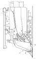
図1に示すように、左右一対のクローラ式走行装置1、運転座席2を有した搭乗型の運転部などを備えた自走機体の機体フレーム3の前部に、刈取り前処理部4の前処理部フレーム4aの基部を機体横向きの軸芯まわりで回動自在に連結するとともに、前記前処理部フレーム4aにリフトシリンダ5を連動させ、前記機体フレーム3に脱穀装置6、穀粒タンク7を設けてコンバインを構成してある。Embodiments of the present invention will be described below with reference to the drawings.
As shown in FIG. 1, a front part of a
このコンバインは、稲・麦などの穀粒を収穫するものであり、前記リフトシリダ5を操作すると、このリフトシリンダ5が前処理部フレーム4aを機体フレーム3に対して上下に揺動操作して刈取り前処理部4を引起し装置4bの下部が地面上近くに位置した下降作業状態と、引起し装置4bが地面から高く浮上した上昇非作業状態とに昇降操作する。刈取り前処理部4を下降作業状態にして自走機体を走行させると、刈取り前処理部4は、植立穀稈を引起し装置4bによって引起し処理しながらバリカン型の刈取装置4cに供給して刈取り処理し、刈取穀稈を搬送装置4dによって機体後方向きに搬送して脱穀装置6の脱穀フィードチェーン6aの始端部に供給する。脱穀装置6は、脱穀フィードチェーン6aによって刈取穀稈の株元側を機体後方側に搬送しながらその穂先側を扱き室(図示せず)に供給して脱穀処理する。穀粒タンク7は、脱穀装置6からの脱穀粒を回収して貯留していく。 This combine harvests grains such as rice and wheat, and when the
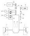
自走機体の前記運転座席2の下方にエンジン8を設け、このエンジン8の駆動力を左右の走行装置1,1に伝達する走行用伝動系、前記エンジン8の駆動力を刈取り前処理部4に伝達する作業用伝動系を、図2に示す如く構成してある。
すなわち、走行用伝動系は、エンジン8の出力軸8aの駆動力を伝動ベルト9を利用して主変速装置10の入力軸11に伝達し、この主変速装置10の出力軸12の駆動力をミッションケース20に伝達してこのミッションケース20の内部でギヤ式減速機構(図示せず)を介して左右一対の操向クラッチ21に伝達し、左側の操向クラッチ21の回転出力をミッションケース20の左横側から出力して左側の走行装置1のクローラ駆動スプロケット1aに伝達し、右側の操向クラッチ21の回転出力をミッションケース20の右横側から出力して右側の走行装置1のクローラ駆動スプロケット1aに伝達するように構成してある。
作業用伝動系は、前記主変速装置10の前記出力軸12の駆動力をミッションケース20の作業用出力軸22に伝達し、この作業用出力軸22の駆動力を伝動ベルト23を利用して刈取り前処理部4の入力軸4eに伝達するように構成してある。An engine 8 is provided below the driver's
That is, the traveling transmission system transmits the driving force of the
The work transmission system transmits the drive force of the
前記主変速装置10は、前記入力軸11によってシリンダブロック(図示せず)が駆動されるように構成したアキシャルプランジャ形で、かつ可変容量形の油圧ポンプ13と、この油圧ポンプ13からの圧油によって駆動されて前記出力軸12から出力するアキシャルプランジャ形の油圧モータ14とを備えて構成してあり、静油圧式無段変速装置になっている。
すなわち、油圧ポンプ13の斜板角の変更操作が行なわれることにより、エンジン8からの駆動力を前進駆動力に変換して左右の走行装置1,1に伝達する前進伝動状態と、エンジン8からの駆動力を後進駆動力に変換して左右の走行装置1,1に伝達する後進伝動状態と、油圧モータ14の駆動を停止して左右の走行装置1,1に対する伝動を絶つ中立状態とに切り換わるようになっている。また、前進伝動状態においても後進伝動状態においてもエンジン8からの駆動力を無段階に変速して左右の走行装置1,1に伝達するようになっている。The
That is, when the swash plate angle of the
主変速装置10を構成する前記油圧モータ14は、前記油圧ポンプ13の容量の1倍以上の容量を有する可変容量形の油圧モータに構成してある。これにより、油圧モータ14は、主変速装置10と直列に並び合った状態で走行用伝動系に設けられた副変速装置になっており、この油圧モータ14の斜板角の変更操作が行なわれることにより、エンジン8からの駆動力を副変速して左右の走行装置1,1に伝達するようになっている。 The
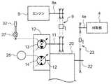
図2に示すように、主変速装置10の油圧ポンプ13の斜板操作軸(図示せず)に電動式の主変速モータ25を連動させて、この主変速モータ25によって主変速装置10を変速操作するように構成し、前記油圧モータ14の斜板操作軸(図示せず)に電動式の副変速モータ26を連動させて、この副変速モータ26によって油圧モータ14を変速操作するように構成してある。図4に示すように、主変速モータ25及び副変速モータ26を変速制御手段27に連係させてある。 As shown in FIG. 2, an electric
図3に示すように、運転部の運転座席2の横側方に、レバーガイド30のガイド溝31に案内されて機体前後方向に揺動操作するように構成した主変速レバー32、この主変速レバー32の横側近くに位置させて前記レバーガイド30に設置した複数個の副変速手段33,34,35及び1個の主副変速モード選択手段36を設けてある。図4に示すように、前記主変速レバー32に検出作用するレバー位置検出手段37、前記各副変速手段33,34,35、前記主副変速モード選択手段36も、前記変速制御手段27に連係させてある。油圧ポンプ13の斜板操作軸の操作位置に基いて主変速装置10の変速状態を検出する主変速センサ38、及び、油圧モータ14の斜板操作軸の操作位置に基いて油圧モータ14の変速状態を検出する副変速センサ39も変速制御手段27に連係させてある。前記エンジン8の出力回転数を検出するエンジン回転センサ40も、走行装置1の駆動速度を検出する速度センサ41も前記変速制御手段27に連係させてある。 As shown in FIG. 3, a main
前記レバー位置検出手段37は、主変速レバー32に操作部が連動されたポテンショメータによって構成してあり、主変速レバー32が主変速装置10を中立状態に操作する中立位置N、主変速装置10を前進伝動状態に操作する前進域F、主変速装置10を後進伝動状態に操作する後進域Rのいずれの操作位置や操作域に操作されたかを検出し、さらに、主変速レバー32が前進域Fや後進域Rにおけるいずれの操作位置に操作されたかを検出し、この検出結果を電気信号にして変速制御手段27に出力する。 The lever position detecting means 37 is constituted by a potentiometer having an operation unit linked to the
主副変速モード選択手段36は、押しボタン式のモード選択スイッチで成り、押し操作されることによって主副変速モード指令を変速制御手段27に出力する。 The main / sub shift mode selection means 36 is composed of a push button type mode selection switch, and outputs a main / sub shift mode command to the shift control means 27 when pressed.
前記複数個の副変速手段33,34,35は、押しボタン式の副変速スイッチで成り、各副変速手段33,34,35は、押し操作されることによって副変速モード指令を変速制御手段27に出力する。また、複数個の副変速手段33,34,35のうちの高速用の副変速手段33は、押し操作されると、副変速モード指令の他に、油圧モータ14を高速の副変速状態に切り換え操作させるべく高速副変速指令も変速制御手段27に出力する。複数個の副変速手段33,34,35のうちの標準用の副変速手段34は、押し操作されると、副変速モード指令の他に、油圧モータ14を中速の副変速状態に切り換え操作させるべき中速副変速指令も変速制御手段27に出力する。複数個の副変速手段33,34,35のうちの倒伏用の副変速手段35は、押し操作されると、副変速モード指令の他に、油圧モータ14を低速の副変速状態に切り換え操作させるべき低速副変速指令も変速制御手段27に出力する。The plurality of sub-transmission means 33, 34, and 35 are formed of push-button sub-transmission switches, and each sub-transmission means 33, 34, and 35 are operated to push a sub-transmission mode command by the shift control means 27. Output to. Further, when the high-speed sub-transmission means 33 among the plurality of sub-transmission means 33, 34, 35 is pushed, the
変速制御手段27は、マイクロコンピュータを利用して成り、前記主副変速モード選択手段36、前記各副変速手段33,34,35、前記レバー位置検出手段37からの情報を基に、図5〜8に示す如く作動する。 The shift control means 27 is made up of a microcomputer, and is based on the information from the main / sub shift mode selection means 36, the auxiliary shift means 33, 34, 35, and the lever position detection means 37 as shown in FIG. It operates as shown in FIG.
すなわち、図5に示すように、変速制御手段27は、主副変速モード選択手段36から主副変速モード指令を入力すると、主副変速制御モードに切り換わって主副変速制御を実行する。つまり、図7に示すように、レバー位置検出手段37による検出情報を基に主変速レバー32が操作されたか否かを判断し、主変速レバー32が操作されたと判断すると、レバー位置検出手段37による検出情報を基に、主変速センサ38による検出情報に基いて主変速装置10が制御目標変速状態になったと判断するまで主変速モータ25を駆動操作し、主変速装置10を主変速レバー32の操作位置に対応する変速状態に変速操作する。さらに、レバー位置検出手段37による検出情報を基に、副変速センサ39による検出情報に基いて油圧モータ14が制御目標副変速状態になったと判断するまで副変速モータ26を駆動操作し、油圧モータ14を主変速レバー32の操作位置に対応する副変速状態に変速操作する。油圧モータ14の変速操作についてさらに詳述すると、図9に示すように、主変速レバー32が前進域Fや後進域Rの低速部に操作された場合には、油圧モータ14を低速の副変速状態に変速操作し、主変速レバー32が前進域Fや後進域Rの中速部に操作された場合には、油圧モータ14を中速の副変速状態に変速操作し、主変速レバー32が前進域Fや後進域Rの高速部に操作された場合には、油圧モータ14を高速の副変速状態に変速操作する。 That is, as shown in FIG. 5, when the main / sub shift mode command is input from the main / sub shift
図5に示すように、変速制御手段27は、副変速手段33,34,35から副変速モード指令を入力すると、副変速制御モードに切り換わり、主変速制御と副変速制御を実行する。つまり、図6に示すように、レバー位置検出手段37による検出情報を基に主変速レバー32が操作されたか否かを判断し、主変速レバー32が操作されたと判断すると、レバー位置検出手段37による検出情報を基に、主変速センサ38による検出情報に基いて主変速装置10が制御目標変速状態になったと判断するまで主変速モータ25を駆動操作し、主変速装置10を主変速レバー32の操作位置に対応する変速状態に変速操作する。さらに、図8のステップ1〜4に示すように、高速用の副変速手段33から高速副変速指令を入力すると、この高速副変速指令を基に、副変速センサ39による検出情報に基いて油圧モータ14が制御目標副変速状態になったと判断するまで副変速モータ26を駆動し、油圧モータ14を高速副変速指令に対応する高速の変速状態に変速操作する。図8のステップ5〜7に示すように、標準用の副変速手段34から中速副変速指令を入力すると、この中速副変速指令を基に、副変速センサ39による検出情報に基いて油圧モータ14が制御目標副変速状態になったと判断するまで副変速モータ26を駆動し、油圧モータ14を中速副変速指令に対応する中速の副変速状態に変速操作する。図8のステップ8〜10に示すように、倒伏用の副変速手段35から低速副変速指令を入力すると、この低速副変速指令を基に、副変速センサ39による検出情報に基いて油圧モータ14が制御目標副変速状態になったと判断するまで副変速モータ26を駆動し、油圧モータ14を低速副変速指令に対応する低速の副変速状態に変速操作する。 As shown in FIG. 5, when the sub-transmission mode command is input from the
変速制御手段27は、エンジン回転センサ40による検出エンジン回転数と、速度センサ41による検出速度を基に、走行装置1の駆動負荷を演算し、この演算駆動負荷が設定値以上の負荷になったか否かを判断し、演算駆動負荷が設定値以上になったと判断した場合、副変速モータ26をレバー位置検出手段37からの検出情報や各副変速手段33,35からの副変速指令に優先して駆動操作し、主変速レバー32が操作されている操作位置にかかわらず、かつ高速や中速用の副変速指令にかかわらず、油圧モータ14を低速の副変速状態に変速操作する。 The shift control means 27 calculates the driving load of the traveling device 1 based on the engine speed detected by the
つまり、倒伏が激しくない穀稈を刈り取るなど、通常の作業走行を行なうに当たり、主副変速モード選択手段36を押し操作する。すると、この主副変速モード選択手段36が出力する主副変速モード指令のために変速制御手段27が主副変速制御モードに切り換わり、変速制御手段27は、レバー位置検出手段37による検出情報を基に主変速モータ25及び副変速モータ26を操作して主変速装置10及び油圧モータ14を主変速レバー32の操作位置に対応する変速状態に切り換え操作するのであり、主変速レバー32を操作するだけで、主変速装置10を無段階に変速操作することによって走行装置1の駆動速度を変更する主変速と、油圧モータ14を低、中、高速の3段階の副変速状態に切り換えることによって走行装置1の駆動速度を変更する副変速とを一挙に行ないながら走行することができる。 In other words, the main / sub transmission mode selection means 36 is pushed to perform normal work travel such as harvesting cereals that are not overly laid down. Then, the shift control means 27 is switched to the main / sub shift control mode for the main / sub shift mode command output by the main / sub shift mode selection means 36, and the shift control means 27 detects the information detected by the lever position detection means 37. Based on this, the
移動走行の際や、倒伏が激しい穀稈を刈り取るなどの作業走行の際、複数個の副変速手段33,34,35から所定の副変速手段33,34,35を選択して押し操作する。すると、押し操作された副変速手段33,34,35が出力する副変速指令のために変速制御手段27が副変速制御モードに切り換わり、変速制御手段27は、レバー位置検出手段37による検出情報を基に主変速モータ25を操作して主変速装置10を主変速レバー32の操作位置に対応する変速状態に切り換え操作する。これとともに、変速制御手段27は、副変速手段33,34,35からの副変速指令を基に副変速モータ26をレバー位置検出手段37による検出情報に優先して操作して油圧モータ14を副変速指令に対応する副変速状態に切り換え操作するのであり、高速用の副変速手段33を操作した場合には、油圧モータ14を高速の副変速状態に固定しながら、標準用の副変速手段34を操作した場合には、油圧モータ14を中速の副変速状態に固定しながら、倒伏用の副変速手段35を操作した場合には、油圧モータ14を低速の副変速状態に固定しながら、いずれの場合も、主変速レバー32によって主変速装置10を無段階に変速操作して走行装置1の駆動速度を変更しながら走行することができる。 When traveling, or during work traveling such as harvesting cereals that are heavily laid down, a predetermined sub-transmission means 33, 34, 35 is selected from a plurality of sub-transmission means 33, 34, 35 and pushed. Then, the shift control means 27 switches to the sub shift control mode for the sub shift command output by the pushed sub shift means 33, 34, 35, and the shift control means 27 detects the information detected by the lever position detection means 37. Based on this, the
また、左右一対の操向クラッチ21,21を操作して機体を旋回走行させる際など、走行装置1の駆動負荷が設定値以上になると、このときの主変速レバー32の操作位置にかかわらず、かつ、副変速手段33による高速副変速指令や、副変速手段34による中速副変速指令にかかわらず、変速制御手段27が油圧モータ14を低速の副変速状態に切り換え操作するのであり、走行装置1の駆動負荷の増大に起因するエンジン8の負荷増大を抑制しながら走行することができる。 In addition, when the driving load of the traveling device 1 becomes a set value or more, such as when the pair of left and
図10(イ)は、別の実施形態を有した操作部構造を備えた走行用変速操作装置を示し、この走行用変速操作装置の操作部構造にあっては、主変速レバー32の握り部32aに1個の副変速手段42を設けてある。
この副変速手段42は、押しボタン式の副変速スイッチで成り、押し操作されると、副変速モード指令と副変速指令を変速制御手段27に出力するようになっている。さらに、この副変速手段42は、図10(ロ)に示す如く押し操作される毎に副変速指令を高速副変速指令と中速副変速指令と低速副変速指令とに順次に切り換えて出力するようになっている。FIG. 10 (a) shows a traveling speed change operation device having an operation portion structure having another embodiment. In the operation portion structure of this travel speed change operation device, the grip portion of the main
The sub-transmission means 42 is composed of a push button type sub-transmission switch, and outputs a sub-transmission mode command and a sub-transmission command to the shift control means 27 when pressed. Further, the sub-transmission means 42 sequentially switches the sub-shift command to the high-speed sub-shift command, the medium-speed sub-shift command, and the low-speed sub-shift command each time it is pushed as shown in FIG. It is like that.
〔別の実施形態〕
上記実施形態の如く、主変速レバー32をレバー位置検出手段37、変速制御手段27、主変速モータ25を介して主変速装置10の油圧ポンプ13の斜板操作軸に連係させることにより、主変速レバー32による主変速装置10の変速操作を可能に構成する他、図11に示す如く構成して実施してもよい。すなわち、主変速レバー32を主変速装置10の油圧ポンプ13の斜板操作軸にリンクを利用した機械式連動手段によって連動させることにより、主変速レバー32による主変速装置10の変速操作を可能にする構成を採用して実施してよく、この場合も本発明の目的を達成することができる。[Another embodiment]
As in the above-described embodiment, the
副変速モータ26に替えてシリンダやソレノイドなどを採用し、これらによって油圧モータ14の副変速状態を切り換えるように構成して実施しても、本発明の目的を達成することができる。従って、これら副変速モータ26、シリンダ、ソレノイドなどを総称して副変速アクチュエータ26と呼称する。 The object of the present invention can also be achieved by adopting a cylinder, a solenoid or the like instead of the
1 走行装置
8 エンジン
10 主変速装置
13 油圧ポンプ
14油圧モータ(副変速装置)
26 副変速アクチュエータ
32 主変速レバー
33,34,35,42 副変速手段
36 主副変速モード選択手段
37 レバー位置検出手段1 Traveling device 8
13
26
Claims (4)
Translated fromJapanese前記主変速装置を変速操作する主変速レバーの操作位置を検出するレバー位置検出手段と、副変速指令を出力する副変速手段と、前記副変速装置を変速操作する副変速アクチュエータとを設け、
前記主変速装置を前記主変速レバーの操作位置に対応する変速状態になるように操作し、かつ、前記レバー位置検出手段による検出情報に基づいて前記副変速装置が前記主変速レバーの操作位置に対応する変速状態に切り換えられるように前記副変速アクチュエータを操作する主副変速制御モードと、前記主変速装置を前記主変速レバーの操作位置に対応する変速状態になるように操作し、かつ、前記副変速手段からの副変速指令に基づいて前記副変速装置が前記副変速手段からの副変速指令に対応する変速状態に切り換えられて固定されるように前記レバー位置検出手段による検出情報に優先して前記副変速アクチュエータを操作する副変速制御モードとに切り換え自在な変速制御手段を設け、前記変速制御手段を前記主副変速制御モードと前記副変速制御モードとに切り換えるモード切り換え手段を設け、
前記副変速手段が、移動走行用の高速副変速指令と、標準用の中速副変速指令と、倒伏の激しい穀稈を刈り取る倒伏用の低速副変速指令とを指令自在に構成され、前記副変速制御モードにおいて、前記副変速装置が、前記高速副変速指令に対応する所定の高速変速状態と、前記中速副変速指令に対応する所定の中速変速状態と、前記低速副変速指令に対応する所定の低速変速状態とに切り換えられるように構成されているコンバインの走行用変速操作装置。A traveling speed change operation device for acombine that includes a main transmission device and a sub-transmission device provided in series with a transmission system that transmits power from the engine to the traveling device,
A lever position detecting means for detecting an operation position of a main transmission lever for shifting the main transmission, a sub transmission means for outputting a sub transmission command,and a sub transmission actuatorfor operating the sub transmission.
It said main transmission was operated so as to shift state corresponding to the operating position of the main speed change lever, and,on the basis of the information detected by the lever position detector auxiliary transmission device in the operating position ofthe main speed change lever A main auxiliary transmission control mode for operating the auxiliary transmission actuator tobe switched to a corresponding transmission state, operating the main transmissionto a transmission state corresponding to the operation position of the main transmission lever, andbased on the sub-shift command from the subtransmission means in preference to information detected bythe lever position detecting means so thatthe auxiliary speed change deviceis fixed is switched to the shift state corresponding to the sub transmission instruction fromthe subtransmission means Shift control means switchable to a sub shift control mode for operating the sub shift actuator is provided, and the shift control means is connected to the main sub shift control mode. Provided mode switching means for switching to said auxiliary shifting controlmode,
The sub-transmission means is configured to be capable of commanding a high-speed sub-transmission command for traveling, a medium-speed sub-transmission command for standard use, and a low-speed sub-transmission command for lodging to harvest harsh fallen rice straw. In the shift control mode, the sub-transmission device corresponds to a predetermined high speed shift state corresponding to the high speed sub shift command, a predetermined medium speed shift state corresponding to the medium speed sub shift command, and the low speed sub shift command. A traveling speed change operation device for acombine that is configured to be switched to a predetermined low speed shifting state .
前記副変速装置を前記静油圧式無段変速装置の油圧モータで構成し、前記油圧モータを、前記高速変速状態と、前記中速変速状態と、前記低速変速状態とに操作自在な可変容量形に構成してある請求項1又は2記載のコンバインの走行用変速操作装置。Constitutethe main speed change device by the hydrostatic continuously variabletransmission, the main transmission device configured to shift operations by operating the hydraulic pump of the hydrostatic continuously variable transmission,
Said auxiliary transmission deviceis constituted by a hydraulic motorofthe hydrostatic continuously variabletransmission, said hydraulic motor, and the high-speed shifting state, and the medium speed shifting state, operably variable displacement to said low-speed shifting state Thecombine shift operating deviceaccording to claim 1 or 2,which is configured as described above.
Priority Applications (1)
| Application Number | Priority Date | Filing Date | Title |
|---|---|---|---|
| JP2004078628AJP4393237B2 (en) | 2004-03-18 | 2004-03-18 | Combined travel shift operating device |
Applications Claiming Priority (1)
| Application Number | Priority Date | Filing Date | Title |
|---|---|---|---|
| JP2004078628AJP4393237B2 (en) | 2004-03-18 | 2004-03-18 | Combined travel shift operating device |
Related Child Applications (1)
| Application Number | Title | Priority Date | Filing Date |
|---|---|---|---|
| JP2008165732ADivisionJP4897744B2 (en) | 2008-06-25 | 2008-06-25 | Combine |
Publications (2)
| Publication Number | Publication Date |
|---|---|
| JP2005265052A JP2005265052A (en) | 2005-09-29 |
| JP4393237B2true JP4393237B2 (en) | 2010-01-06 |
Family
ID=35089829
Family Applications (1)
| Application Number | Title | Priority Date | Filing Date |
|---|---|---|---|
| JP2004078628AExpired - Fee RelatedJP4393237B2 (en) | 2004-03-18 | 2004-03-18 | Combined travel shift operating device |
Country Status (1)
| Country | Link |
|---|---|
| JP (1) | JP4393237B2 (en) |
Families Citing this family (9)
| Publication number | Priority date | Publication date | Assignee | Title |
|---|---|---|---|---|
| JP2007230518A (en)* | 2006-03-03 | 2007-09-13 | Yanmar Co Ltd | Operation part for tractor |
| JP5108699B2 (en)* | 2008-09-24 | 2012-12-26 | 株式会社クボタ | Mowing harvester |
| JP5108681B2 (en)* | 2008-08-21 | 2012-12-26 | 株式会社クボタ | Combine |
| KR101065563B1 (en) | 2008-05-09 | 2011-09-19 | 가부시끼 가이샤 구보다 | Harvester |
| KR101696452B1 (en) | 2008-09-26 | 2017-01-13 | 가부시끼 가이샤 구보다 | Reaping harvester |
| JP5215122B2 (en)* | 2008-10-27 | 2013-06-19 | 株式会社クボタ | Working gear shifting structure |
| JP2010159804A (en)* | 2009-01-07 | 2010-07-22 | Kubota Corp | Travel control device for working vehicle |
| JP5215196B2 (en)* | 2009-01-08 | 2013-06-19 | 株式会社クボタ | Work vehicle travel control device |
| JP5285444B2 (en)* | 2009-01-14 | 2013-09-11 | 株式会社クボタ | Combine traveling control device |
- 2004
- 2004-03-18JPJP2004078628Apatent/JP4393237B2/ennot_activeExpired - Fee Related
Also Published As
| Publication number | Publication date |
|---|---|
| JP2005265052A (en) | 2005-09-29 |
Similar Documents
| Publication | Publication Date | Title |
|---|---|---|
| JP6615085B2 (en) | Harvesting machine | |
| JP4393237B2 (en) | Combined travel shift operating device | |
| JP4897744B2 (en) | Combine | |
| JP4529920B2 (en) | Combine | |
| JP5452114B2 (en) | Combine | |
| JP2007228837A5 (en) | ||
| JP2007252322A (en) | Drive control device for work vehicle | |
| JP5249888B2 (en) | Movable harvester travel transmission | |
| JP5739275B2 (en) | Agricultural machine travel transmission device | |
| JP2010178630A (en) | Combined harvester | |
| JP2007174972A (en) | Work vehicle | |
| JP2007174972A5 (en) | ||
| JP3756140B2 (en) | Shift control device for harvesting machine | |
| JP5005594B2 (en) | Combine threshing / reaping clutch control device | |
| JP5564016B2 (en) | Agricultural machine travel transmission device | |
| JP5232026B2 (en) | Mowing harvester | |
| JP5308113B2 (en) | Combine shift control device | |
| JP5108681B2 (en) | Combine | |
| JP2007252321A (en) | Drive control device for work vehicle | |
| JP5322466B2 (en) | Combine threshing / reaping clutch control device | |
| JP4585373B2 (en) | Work vehicle travel transmission device | |
| JP5225127B2 (en) | Combine | |
| JP2007094825A (en) | Working vehicle operating device | |
| JP5232028B2 (en) | Mowing harvester | |
| JP2006042605A (en) | Self-removing combine |
Legal Events
| Date | Code | Title | Description |
|---|---|---|---|
| A621 | Written request for application examination | Free format text:JAPANESE INTERMEDIATE CODE: A621 Effective date:20060323 | |
| A977 | Report on retrieval | Free format text:JAPANESE INTERMEDIATE CODE: A971007 Effective date:20090616 | |
| A131 | Notification of reasons for refusal | Free format text:JAPANESE INTERMEDIATE CODE: A131 Effective date:20090709 | |
| A521 | Request for written amendment filed | Free format text:JAPANESE INTERMEDIATE CODE: A523 Effective date:20090907 | |
| TRDD | Decision of grant or rejection written | ||
| A01 | Written decision to grant a patent or to grant a registration (utility model) | Free format text:JAPANESE INTERMEDIATE CODE: A01 Effective date:20091001 | |
| A01 | Written decision to grant a patent or to grant a registration (utility model) | Free format text:JAPANESE INTERMEDIATE CODE: A01 | |
| A61 | First payment of annual fees (during grant procedure) | Free format text:JAPANESE INTERMEDIATE CODE: A61 Effective date:20091013 | |
| R150 | Certificate of patent or registration of utility model | Ref document number:4393237 Country of ref document:JP Free format text:JAPANESE INTERMEDIATE CODE: R150 Free format text:JAPANESE INTERMEDIATE CODE: R150 | |
| FPAY | Renewal fee payment (event date is renewal date of database) | Free format text:PAYMENT UNTIL: 20121023 Year of fee payment:3 | |
| FPAY | Renewal fee payment (event date is renewal date of database) | Free format text:PAYMENT UNTIL: 20131023 Year of fee payment:4 | |
| LAPS | Cancellation because of no payment of annual fees |