JP4392649B2 - Amorphous alloy member, method for producing the same, and component using the same - Google Patents
Amorphous alloy member, method for producing the same, and component using the sameDownload PDFInfo
- Publication number
- JP4392649B2 JP4392649B2JP2003295937AJP2003295937AJP4392649B2JP 4392649 B2JP4392649 B2JP 4392649B2JP 2003295937 AJP2003295937 AJP 2003295937AJP 2003295937 AJP2003295937 AJP 2003295937AJP 4392649 B2JP4392649 B2JP 4392649B2
- Authority
- JP
- Japan
- Prior art keywords
- amorphous
- amorphous alloy
- alloy member
- alloy
- film
- Prior art date
- Legal status (The legal status is an assumption and is not a legal conclusion. Google has not performed a legal analysis and makes no representation as to the accuracy of the status listed.)
- Expired - Fee Related
Links
- 229910000808amorphous metal alloyInorganic materials0.000titleclaimsdescription83
- 238000004519manufacturing processMethods0.000titleclaimsdescription18
- 229910045601alloyInorganic materials0.000claimsdescription60
- 239000000956alloySubstances0.000claimsdescription60
- 239000010419fine particleSubstances0.000claimsdescription51
- 239000007789gasSubstances0.000claimsdescription37
- 239000000758substrateSubstances0.000claimsdescription33
- 239000002245particleSubstances0.000claimsdescription16
- 150000004767nitridesChemical class0.000claimsdescription13
- 239000000843powderSubstances0.000claimsdescription13
- KRHYYFGTRYWZRS-UHFFFAOYSA-MFluoride anionChemical compound[F-]KRHYYFGTRYWZRS-UHFFFAOYSA-M0.000claimsdescription12
- 230000008021depositionEffects0.000claimsdescription8
- 239000000203mixtureSubstances0.000claimsdescription7
- 229910052760oxygenInorganic materials0.000claimsdescription6
- 229910052757nitrogenInorganic materials0.000claimsdescription5
- 230000009477glass transitionEffects0.000claimsdescription4
- 229910001361White metalInorganic materials0.000claimsdescription3
- 229910052782aluminiumInorganic materials0.000claimsdescription3
- 229910052787antimonyInorganic materials0.000claimsdescription3
- 229910052785arsenicInorganic materials0.000claimsdescription3
- 229910052790berylliumInorganic materials0.000claimsdescription3
- 229910052797bismuthInorganic materials0.000claimsdescription3
- 229910052796boronInorganic materials0.000claimsdescription3
- 229910052799carbonInorganic materials0.000claimsdescription3
- 229910052804chromiumInorganic materials0.000claimsdescription3
- 229910052802copperInorganic materials0.000claimsdescription3
- 238000002425crystallisationMethods0.000claimsdescription3
- 230000008025crystallizationEffects0.000claimsdescription3
- 229910052733galliumInorganic materials0.000claimsdescription3
- 229910052732germaniumInorganic materials0.000claimsdescription3
- 229910052737goldInorganic materials0.000claimsdescription3
- 229910052735hafniumInorganic materials0.000claimsdescription3
- 229910052738indiumInorganic materials0.000claimsdescription3
- 229910052742ironInorganic materials0.000claimsdescription3
- 229910052748manganeseInorganic materials0.000claimsdescription3
- 229910052750molybdenumInorganic materials0.000claimsdescription3
- 229910052758niobiumInorganic materials0.000claimsdescription3
- 229910052698phosphorusInorganic materials0.000claimsdescription3
- 229910052761rare earth metalInorganic materials0.000claimsdescription3
- 229910052702rheniumInorganic materials0.000claimsdescription3
- 229910052711seleniumInorganic materials0.000claimsdescription3
- 229910052710siliconInorganic materials0.000claimsdescription3
- 229910052709silverInorganic materials0.000claimsdescription3
- 229910052717sulfurInorganic materials0.000claimsdescription3
- 229910052715tantalumInorganic materials0.000claimsdescription3
- 229910052714telluriumInorganic materials0.000claimsdescription3
- 229910052718tinInorganic materials0.000claimsdescription3
- 229910052720vanadiumInorganic materials0.000claimsdescription3
- 239000010969white metalSubstances0.000claimsdescription3
- 229910052727yttriumInorganic materials0.000claimsdescription3
- 229910052725zincInorganic materials0.000claimsdescription3
- 229910052726zirconiumInorganic materials0.000claimsdescription3
- 239000012159carrier gasSubstances0.000claimsdescription2
- 239000010408filmSubstances0.000description66
- 238000000034methodMethods0.000description21
- 238000010438heat treatmentMethods0.000description18
- 230000015572biosynthetic processEffects0.000description15
- 239000011162core materialSubstances0.000description12
- IJGRMHOSHXDMSA-UHFFFAOYSA-NAtomic nitrogenChemical compoundN#NIJGRMHOSHXDMSA-UHFFFAOYSA-N0.000description11
- 238000002441X-ray diffractionMethods0.000description11
- 230000005540biological transmissionEffects0.000description11
- 239000013078crystalSubstances0.000description11
- 125000001475halogen functional groupChemical group0.000description9
- 238000000151depositionMethods0.000description8
- 238000012387aerosolizationMethods0.000description7
- 239000000919ceramicSubstances0.000description7
- 229910001873dinitrogenInorganic materials0.000description7
- 238000004544sputter depositionMethods0.000description7
- UFHFLCQGNIYNRP-UHFFFAOYSA-NHydrogenChemical compound[H][H]UFHFLCQGNIYNRP-UHFFFAOYSA-N0.000description6
- YCKRFDGAMUMZLT-UHFFFAOYSA-NFluorine atomChemical compound[F]YCKRFDGAMUMZLT-UHFFFAOYSA-N0.000description5
- 229910052731fluorineInorganic materials0.000description5
- 239000011737fluorineSubstances0.000description5
- 239000000696magnetic materialSubstances0.000description5
- 239000010409thin filmSubstances0.000description5
- 230000004907fluxEffects0.000description4
- 238000009689gas atomisationMethods0.000description4
- 239000011521glassSubstances0.000description4
- 229910052751metalInorganic materials0.000description4
- 239000002184metalSubstances0.000description4
- 238000005096rolling processMethods0.000description4
- 238000007740vapor depositionMethods0.000description4
- 238000004804windingMethods0.000description4
- QVGXLLKOCUKJST-UHFFFAOYSA-Natomic oxygenChemical compound[O]QVGXLLKOCUKJST-UHFFFAOYSA-N0.000description3
- 230000000694effectsEffects0.000description3
- 230000003287optical effectEffects0.000description3
- 239000001301oxygenSubstances0.000description3
- 230000008569processEffects0.000description3
- XKRFYHLGVUSROY-UHFFFAOYSA-NArgonChemical compound[Ar]XKRFYHLGVUSROY-UHFFFAOYSA-N0.000description2
- MYMOFIZGZYHOMD-UHFFFAOYSA-NDioxygenChemical compoundO=OMYMOFIZGZYHOMD-UHFFFAOYSA-N0.000description2
- 239000000443aerosolSubstances0.000description2
- 238000006243chemical reactionMethods0.000description2
- 239000011248coating agentSubstances0.000description2
- 238000000576coating methodMethods0.000description2
- 229910001882dioxygenInorganic materials0.000description2
- 239000001257hydrogenSubstances0.000description2
- 229910052739hydrogenInorganic materials0.000description2
- 239000011261inert gasSubstances0.000description2
- 239000012528membraneSubstances0.000description2
- 229910052759nickelInorganic materials0.000description2
- 238000000059patterningMethods0.000description2
- 238000010298pulverizing processMethods0.000description2
- 238000010791quenchingMethods0.000description2
- 230000000171quenching effectEffects0.000description2
- 239000011347resinSubstances0.000description2
- 229920005989resinPolymers0.000description2
- 239000000523sampleSubstances0.000description2
- 239000013526supercooled liquidSubstances0.000description2
- 238000011282treatmentMethods0.000description2
- 229910052721tungstenInorganic materials0.000description2
- 238000009692water atomizationMethods0.000description2
- QGZKDVFQNNGYKY-UHFFFAOYSA-NAmmoniaChemical compoundNQGZKDVFQNNGYKY-UHFFFAOYSA-N0.000description1
- 229910019230CoFeSiBInorganic materials0.000description1
- 238000004458analytical methodMethods0.000description1
- 229910052786argonInorganic materials0.000description1
- 230000008901benefitEffects0.000description1
- 239000011230binding agentSubstances0.000description1
- 230000000052comparative effectEffects0.000description1
- 230000007797corrosionEffects0.000description1
- 238000005260corrosionMethods0.000description1
- 238000005520cutting processMethods0.000description1
- 238000009826distributionMethods0.000description1
- 239000000428dustSubstances0.000description1
- 150000002222fluorine compoundsChemical class0.000description1
- 238000007429general methodMethods0.000description1
- 239000001307heliumSubstances0.000description1
- 229910052734heliumInorganic materials0.000description1
- SWQJXJOGLNCZEY-UHFFFAOYSA-Nhelium atomChemical compound[He]SWQJXJOGLNCZEY-UHFFFAOYSA-N0.000description1
- 230000006872improvementEffects0.000description1
- 239000007788liquidSubstances0.000description1
- 229910001004magnetic alloyInorganic materials0.000description1
- 239000000463materialSubstances0.000description1
- 229910001092metal group alloyInorganic materials0.000description1
- 229910052752metalloidInorganic materials0.000description1
- 230000003647oxidationEffects0.000description1
- 238000007254oxidation reactionMethods0.000description1
- 230000009467reductionEffects0.000description1
- 238000005245sinteringMethods0.000description1
- 238000005507sprayingMethods0.000description1
- 238000005211surface analysisMethods0.000description1
- 238000004381surface treatmentMethods0.000description1
- 238000002076thermal analysis methodMethods0.000description1
Images


Landscapes
- Soft Magnetic Materials (AREA)
Description
Translated fromJapanese本発明は、各種チョークコイル、各種トランス、磁気あるいは電流センサ、電磁シールドなどのノイズ対策部品、インバータトランス、アンテナ等の各種磁性部品、アクチュエータなどの機能部品、光学部品、水素透過膜、各種構造部品などに用いられる膜状のアモルファス合金部材およびその製造方法ならびにそれを用いた部品に関する。 The present invention includes various choke coils, various transformers, magnetic or current sensors, noise countermeasure parts such as electromagnetic shields, various magnetic parts such as inverter transformers and antennas, functional parts such as actuators, optical parts, hydrogen permeable membranes and various structural parts. The present invention relates to a film-like amorphous alloy member used for the above, a manufacturing method thereof, and a part using the same.
アモルファス合金は優れた軟磁気特性や優れた機械的特性を示すために注目されており、特に軟磁性材料として配電用トランス、電源用磁性部品、磁気ヘッドなどの用途に実用化されている。これらの合金は一般的に単ロール法、アトマイズ法やスパッタ法などの超急冷法を用いて製造される。このため、単ロール法で製造する場合、アモルファス合金は厚さ数μmから数十μmのリボン状となる。たとえばアモルファス合金リボンを磁心に使用する場合は、巻磁心として使用したり、積層して積層磁心として使うあるいは薄いリボン単体で使用する場合が多い。一方、アトマイズ法は粉末形状のアモルファス合金粉末しか製造できず、これを使用する場合はバインダーを混ぜてプレスし圧粉磁心として使用したり、樹脂と混ぜて使用する。また、場合によっては温度があまり上昇しない放電プラズマ焼結法などを用い固化させて使用する。典型的なアモルファス合金は、FeSiB系合金やCoFeSiB系合金等の金属−半金属系合金、CoNbZrなどの金属−金属系合金等が知られている。 Amorphous alloys are attracting attention because they exhibit excellent soft magnetic properties and excellent mechanical properties. In particular, they are put to practical use in applications such as power distribution transformers, power supply magnetic components, and magnetic heads as soft magnetic materials. These alloys are generally manufactured using a rapid quenching method such as a single roll method, an atomizing method, or a sputtering method. For this reason, when it manufactures by a single roll method, an amorphous alloy becomes a ribbon shape with a thickness of several micrometers to several tens of micrometers. For example, when an amorphous alloy ribbon is used for a magnetic core, it is often used as a wound magnetic core, laminated and used as a laminated magnetic core, or a thin ribbon alone. On the other hand, the atomizing method can produce only powder-form amorphous alloy powder. When using this, the binder is mixed and pressed and used as a dust core, or mixed with resin. Further, in some cases, it is used after being solidified using a discharge plasma sintering method or the like in which the temperature does not rise so much. As typical amorphous alloys, metal-metalloid alloys such as FeSiB alloys and CoFeSiB alloys, metal-metal alloys such as CoNbZr, and the like are known.
磁性材料として高周波の部品に応用する場合は、渦電流損失を低減するために、板厚(膜厚)は薄い方が望ましい。しかしながら、部品として機能を発揮するためにはある程度断面積は大きくする必要がある。
単ロール法などにより作製したアモルファス合金リボンは15μmから30μm程度の板厚のリボンが製造しやすく、可飽和コアなどの電源用部品に巻磁心として使用されている。しかし、より高周波で使用する場合、部品の小型化、集積化や高性能化が必要となり、合金リボンを用いた巻磁心のような形態では部品化への対応が難しく、膜形態で使用した方が複雑形状の部品の場合にはパターン化が容易などの利点も有している。
アモルファス合金膜形成の一般的な方法としては蒸着法やスパッタ法が知られており、薄膜磁気ヘッドや薄膜インダクタに使用されている。しかし、これらの方法は膜形成速度が小さく、しかも2μm以上の厚膜になると膜が剥がれやすい問題があり、アモルファス合金厚膜の製造には適していない。When applied to high-frequency components as a magnetic material, it is desirable that the plate thickness (film thickness) is small in order to reduce eddy current loss. However, the cross-sectional area needs to be increased to some extent in order to exhibit the function as a part.
Amorphous alloy ribbons produced by the single roll method are easy to produce ribbons with a thickness of about 15 μm to 30 μm, and are used as winding cores for power supply components such as saturable cores. However, when using at higher frequencies, it is necessary to reduce the size, integrate and improve the performance of components, and it is difficult to respond to componentization with a wound core using an alloy ribbon. In the case of a component having a complicated shape, there is an advantage that patterning is easy.
As a general method for forming an amorphous alloy film, a vapor deposition method or a sputtering method is known, and is used for a thin film magnetic head or a thin film inductor. However, these methods have a problem that the film formation rate is low, and when the film is thicker than 2 μm, there is a problem that the film is easily peeled off, and it is not suitable for manufacturing an amorphous alloy thick film.
近年、エアロゾルデポジション法(AD法)が開発され、圧電材料等のセラミックスの高速コーティングによる厚膜の作製が検討されおり、特許文献1〜4や非特許文献1等に記載されている。セラミックス微粒子を、エアロゾル化チャンバー内でガスと攪拌・混合してエアロゾル化し、成膜チャンバーとの圧力差によるガスの流れにより成膜チャンバーに搬送し、スリット状のノズルを通して加速、基板に噴射し、セラミックス厚膜を基板上に製造する。この成膜方法は高速に比較的低温でセラミックスの厚膜を形成することができるが、結晶性の良いセラミックスの厚膜を製造のまま、あるいは基板との反応や基板ダメージが小さい比較的低い実用的な温度において熱処理を行い形成することが困難であり、結晶性の良い実用性のある厚膜形成の努力が続けられている。 In recent years, an aerosol deposition method (AD method) has been developed, and production of a thick film by high-speed coating of ceramics such as a piezoelectric material has been studied, and is described in
スパッタや蒸着などの方法による厚膜製造は一般に膜形成速度が低い上に、2μm以上の厚膜になると膜が剥がれやすくなる問題があり、厚膜の実用化には問題がある。スパッタや蒸着法によりアモルファス合金厚膜を製造する場合、アモルファス化するために膜の温度上昇を抑える必要があり、特に金属以外の熱伝導率が小さい基板上にスパッタや蒸着などの方法により膜形成速度を大きくして密着性及び特性が良好なアモルファス合金厚膜を形成することは困難である。
また、従来から知られている単ロール法などのアモルファス合金の製造方法により製造されたアモルファス合金リボンにおいて、通常量産できる板厚は12μmから35μm程度であり、板厚が10μmを切るような場合、形状的な制約、加工時のリボン破断など量産時の生産性の点で前述のように部品化する場合多くの課題がある。複雑形状の厚膜を使用する部品へ適用する場合には効率良く部品を製造することが困難である。特に、リボン板厚が15μm以下のアモルファス合金リボンの場合は、リボン製造が困難であり、板厚が薄いために合金リボンを巻いたり、切断するなどの加工が難しくなる問題点を有している。Thick film production by a method such as sputtering or vapor deposition generally has a low film formation speed, and there is a problem that the film tends to be peeled when the film thickness is 2 μm or more, and there is a problem in practical use of the thick film. When manufacturing an amorphous alloy thick film by sputtering or vapor deposition, it is necessary to suppress the temperature rise of the film in order to make it amorphous. In particular, film formation by sputtering or vapor deposition on a substrate with low thermal conductivity other than metal It is difficult to increase the speed to form an amorphous alloy thick film with good adhesion and characteristics.
In addition, in an amorphous alloy ribbon manufactured by a conventionally known amorphous alloy manufacturing method such as a single roll method, the plate thickness that can be mass-produced is usually about 12 μm to 35 μm, and when the plate thickness is less than 10 μm, There are many problems when making parts as described above in terms of productivity at the time of mass production such as shape restrictions and ribbon breakage during processing. When applied to a part using a thick film having a complicated shape, it is difficult to manufacture the part efficiently. In particular, in the case of an amorphous alloy ribbon having a ribbon plate thickness of 15 μm or less, it is difficult to manufacture the ribbon, and since the plate thickness is thin, there is a problem that processing such as winding or cutting the alloy ribbon becomes difficult. .
高周波用磁性部品の部材としてアモルファス合金を使用する場合、渦電流損失の低減のため板厚を薄くした方が良いが、一方で膜厚が2μmを切るようなスパッタ法などで比較的製造が容易な薄膜形態では断面積が十分でなく、適応できる部品が大幅に制限される。特にパワーエレクトロニクス関係の部品に使用する場合、高周波用途においても2μm以上の膜厚の要求がある。すでに、高周波用として薄膜化による渦電流損失の低減や高抵抗グラニュラー薄膜などが検討されているが、高抵抗グラニュラー薄膜の場合は磁性材料の体積を増加するのに限界があり、高エネルギーを扱うパルスパワーや比較的容量の大きいインバータやスイッチング電源に使用されている可飽和コア、トランス、チョークコイルなどの磁心材料として使用するのは困難である。
また、磁性部品以外の用途においても、表面を硬化させるなどの表面処理、高精度・高強度が要求されるマイクロマシンなどの構造部品の用途があり、高硬度で高強度のアモルファス合金部材が求められているが、従来のリボン状のアモルファスリボンでは高精度に加工することが困難な上に他の部材との複合化が難しい問題がある。When using an amorphous alloy as a member for high-frequency magnetic parts, it is better to reduce the plate thickness in order to reduce eddy current loss, but on the other hand, it is relatively easy to manufacture by sputtering or the like with a film thickness of less than 2 μm. Such thin film forms do not have a sufficient cross-sectional area, greatly limiting the parts that can be accommodated. In particular, when used for components related to power electronics, there is a demand for a film thickness of 2 μm or more even in high frequency applications. Already, reduction of eddy current loss by thinning and high resistance granular thin films have been studied for high frequency applications, but in the case of high resistance granular thin films, there is a limit to increasing the volume of magnetic material, and high energy is handled. It is difficult to use as a magnetic core material such as a saturable core, a transformer, and a choke coil that are used in an inverter or a switching power supply having a pulse power or a relatively large capacity.
In addition to magnetic parts, there are surface treatments such as curing the surface, and structural parts such as micromachines that require high accuracy and high strength, and high hardness and high strength amorphous alloy members are required. However, the conventional ribbon-like amorphous ribbon has a problem that it is difficult to process with high accuracy and difficult to combine with other members.
このような課題を克服する方策として、本発明者らは、アモルファス相が体積分率で50%以上存在する平均粒径1μm以下のアモルファス合金微粒子を作製し、これを基板上に成膜可能な高速で衝突させることにより、アモルファス相が体積分率で50%以上存在し、かつ平均膜厚が2〜20μmである厚膜状のアモルファス合金部材を高速に製造でき、しかも製造したアモルファス合金厚膜は、圧電セラミックス厚膜のように結晶性を改善し特性を発現するために800゜C以上というような高温で熱処理する必要がなく、550゜C以下場合によっては400゜C以下という比較的低い温度で十分特性を発揮可能であり、選定する基板の自由度が高く各種基板を使用可能であることを見出した。As a measure for overcoming such a problem, the present inventors can produce amorphous alloy fine particles having anaverage particle size of 1 μm or less in which an amorphous phase is present in a volume fraction of 50% or more, andcan form this on a substrate. By colliding at high speed, a thick amorphous alloy member having an amorphous phase of 50% or more in volume fraction and an average film thickness of 2 to20 μm can be manufactured at high speed, and the thickness of the manufactured amorphous alloy The film does not need to be heat-treated at a high temperature of 800 ° C. or higher in order to improve crystallinity and exhibit properties like a piezoelectric ceramic thick film, and is relatively less than 550 ° C. and sometimes 400 ° C. or lower. It has been found that the characteristics can be sufficiently exhibited at a low temperature, and the substrate to be selected has a high degree of freedom and various substrates can be used.
本発明は、アモルファス相が体積分率で50%以上存在する平均粒径1μm以下のアモルファス合金微粒子を基板上に成膜可能な高速で衝突させ形成してなる膜状の合金部材であって、アモルファス相が体積分率で50%以上存在し、かつ平均膜厚が2〜20μmであることを特徴とするアモルファス合金部材である。本発明において、アモルファス相が体積分率で50%以上存在する合金をアモルファス合金と呼ぶ。The present invention provides a film-like alloy member obtained by forming to collide withan average particle diameter of 1μm or less of the amorphous alloy particulateinthe deposition can be a high speed on a substratean amorphous phase is present 50% or more by volume fraction, The amorphous alloy member is characterized in that an amorphous phase is present in a volume fraction of 50% or more and an average film thickness is 2 to20 μm. In the present invention, an alloy having an amorphous phase of 50% or more in volume fraction is called an amorphous alloy.
本発明において、一部に酸化物、窒化物、フッ化物から選ばれた少なくとも一つの相が存在した場合、150μΩcmを超える高電気抵抗率のアモルファス合金部材の実現が可能となり、高周波用部品の部材に特に適したアモルファス合金部材が得られる。このような合金部材は粉末製造の際や、熱処理の際の雰囲気ガスを酸素、窒素、フッ素などを含むガスとしたり、アモルファス合金微粒子を基板上に衝突させる際の雰囲気ガスを酸素、窒素、フッ素などを含むガスとすることや、アモルファス合金微粒子表面に化学的、物理的に酸化物、窒化物、フッ化物相をコーティングした微粒子を使用することにより製造される。 In the present invention, when at least one phase selected from oxide, nitride, and fluoride is present in part, an amorphous alloy member having a high electrical resistivity exceeding 150 μΩcm can be realized, and a member for a high-frequency component An amorphous alloy member particularly suitable for the above can be obtained. In such an alloy member, the atmosphere gas at the time of powder production or heat treatment is a gas containing oxygen, nitrogen, fluorine, etc., or the atmosphere gas at the time of colliding amorphous alloy fine particles on the substrate is oxygen, nitrogen, fluorine. Or by using fine particles obtained by chemically and physically coating the surface of amorphous alloy fine particles with oxide, nitride, or fluoride phases.
特に、一般式:M100−x−yM′xXy(原子%(at%))で表され、式中、MはFe,Co,Niから選ばれた少なくとも一種の元素、M′はAl、Zn,Cu,Mn,Cr,V,Ti,Sc,Ag,白金属元素,Mo,Nb,Zr,Y,希土類元素,Au,Re,Hf,Ta,In,Sn,O,S,N,As,Se,Te,Sb,BiおよびWから選ばれた少なくとも一種の元素、XはSi、C、P、Ge、Be、GaおよびBから選ばれた少なくとも1種の元素を示し、xおよびyはそれぞれ0≦x≦20、0≦y≦35、5≦x + y≦35を満足する組成である場合、磁性材料として優れた特性を有するアモルファス合金部材が実現可能である。
ここで、MはFe,Co,Niから選ばれた少なくとも一種の元素であり、磁性材料として必要な元素である。M′はAl、Zn,Cu,Mn,Cr,V,Ti,Sc,Ag,白金属元素,Mo,Nb,Zr,Y,希土類元素,Au,Re,Hf,Ta,In,Sn,O,S,N,As,Se,Te,Sb,BiおよびWから選ばれた少なくとも一種の元素であり、耐食性の向上、磁歪の調整、耐熱性向上、保磁力の調整、アモルファス形成を容易とするなどに効果的な元素である。M′の含有量xは、0≦x≦20である必要がある。この理由はxが20を超えると飽和磁束密度の低下を招いたり、製造が困難になるためである。XはSi、C、P、Ge、Be、GaおよびBから選ばれた少なくとも1種の元素であり、アモルファス相の形成を助ける効果、磁歪やキュリー温度を調整する効果がある。Xの含有量yは0≦y≦35である必要がある。またM′とXの総和x+yは、5≦x + y≦35である必要がある。x + yが5at%未満ではアモルファス相形成が困難となり、x+yが35at%を超えると飽和磁束密度が著しく低下するためである。In particular, it is represented by the general formula: M100-xy M ′x Xy (atomic% (at%)), where M is at least one element selected from Fe, Co and Ni, and M ′ is Al, Zn, Cu, Mn, Cr, V, Ti, Sc, Ag, white metal element, Mo, Nb, Zr, Y, rare earth element, Au, Re, Hf, Ta, In, Sn, O, S, N , As, Se, Te, Sb, Bi and W, X represents at least one element selected from Si, C, P, Ge, Be, Ga and B, and x and When y is a composition satisfying 0 ≦ x ≦ 20, 0 ≦ y ≦ 35, and 5 ≦ x + y ≦ 35, an amorphous alloy member having excellent characteristics as a magnetic material can be realized.
Here, M is at least one element selected from Fe, Co, and Ni, and is an element necessary as a magnetic material. M ′ is Al, Zn, Cu, Mn, Cr, V, Ti, Sc, Ag, white metal element, Mo, Nb, Zr, Y, rare earth element, Au, Re, Hf, Ta, In, Sn, O, It is at least one element selected from S, N, As, Se, Te, Sb, Bi and W, and improves corrosion resistance, magnetostriction adjustment, heat resistance improvement, coercive force adjustment, amorphous formation, etc. It is an effective element. The content x of M ′ needs to satisfy 0 ≦ x ≦ 20. This is because when x exceeds 20, the saturation magnetic flux density is lowered or the manufacture becomes difficult. X is at least one element selected from Si, C, P, Ge, Be, Ga, and B, and has an effect of assisting formation of an amorphous phase and an effect of adjusting magnetostriction and Curie temperature. The X content y needs to satisfy 0 ≦ y ≦ 35. Further, the sum x + y of M ′ and X needs to satisfy 5 ≦ x + y ≦ 35. This is because when x + y is less than 5 at%, it is difficult to form an amorphous phase, and when x + y exceeds 35 at%, the saturation magnetic flux density is significantly reduced.
合金部材中のアモルファス相のガラス遷移温度Tgが結晶化温度Tx未満の温度である場合、特にアモルファス形成能が高く、アモルファス合金微粒子の製造およびアモルファス合金厚膜製造が容易なだけでなく、厚膜形成の際に過冷却液体状態を経由して成膜可能であり、膜の緻密化も図れる。また、Tg以上に加熱し過冷却液体状態とすることにより、厚膜表面を種々のパターン形状に精密加工が可能である。When the glass transition temperature Tg of the amorphous phase in the alloy member is a temperature lower than the crystallization temperature Tx , the amorphous forming ability is particularly high, and not only is it easy to produce amorphous alloy fine particles and amorphous alloy thick film, When the thick film is formed, the film can be formed via the supercooled liquid state, and the film can be densified. Further, with the supercooled liquid state heated above Tg, it is possible to precisely process the thick film surface for various pattern shapes.
もう一つの本発明は、アモルファス相が体積分率で50%以上存在する平均粒径1μm以下のアモルファス合金微粒子を搬送ガスにより基板上に衝突させ、アモルファス相が体積分率で50%以上存在し、かつ厚さが2〜20μmである合金厚膜を基板上に形成することを特徴とするアモルファス合金部材の製造方法である。本製造方法により、上述したアモルファス相が体積分率で50%以上存在する平均粒径1μm以下のアモルファス合金微粒子を基板上に成膜可能な高速で衝突させ形成してなる膜状の合金部材であって、アモルファス相が体積分率で50%以上存在し、かつ平均膜厚が2〜20μmである品質の良好なアモルファス合金部材を生産性良く製造可能である。
平均粒径1μm以下である合金微粒子を用いて製造した場合、表面平滑性の良いアモルファス合金厚膜からなるアモルファス合金部材を製造できるため好ましい。
また、反応性ガス中で熱処理し合金微粒子表面に酸化物、窒化物、フッ化物から選ばれた少なくとも一つの相を形成した合金微粒子を用いた場合、高電気抵抗率のアモルファス合金部材を製造することが可能であり、高周波用磁性合金部材として優れた特性を発揮する。In another aspect of the present invention, amorphous alloy particles having anaverage particle size of 1 μm or less with an amorphous phase existing in a volume fraction of 50% or more are collided on a substrate by a carrier gas, and the amorphous phase exists in a volume fraction of 50% or more. In addition, an amorphous alloy member manufacturing method is characterized in that an alloy thick film having a thickness of 2 to20 μm is formed on a substrate. By this manufacturing method, a film-like alloy member anaverage particle size 1μm or less of the amorphous alloy particulate obtained by forming collidewiththe film formation can be faster on the substrate amorphous phasedescribed above is present more than 50% by volume fraction In addition, it is possible to produce a high quality amorphous alloy member having an amorphous phase with a volume fraction of 50% or more and an average film thickness of 2 to20 μm with high productivity.
When manufactured using alloy fine particles having an average particle size of 1 μm or less, it is preferable because an amorphous alloy member made of an amorphous alloy thick film having good surface smoothness can be manufactured.
In addition, when alloy fine particles that have been heat-treated in a reactive gas and have formed at least one phase selected from oxide, nitride, and fluoride on the surface of the fine alloy particles, an amorphous alloy member having a high electrical resistivity is manufactured. And exhibits excellent properties as a magnetic alloy member for high frequency use.
本発明に係わるアモルファス合金微粒子は、水アトマイズ法やガスアトマイズ法により作製したアモルファス合金粉末あるいはこれらの粉末を粉砕や分級したアモルファス合金微粒子、液体急冷法により作製したアモルファスリボンを粉砕及び分級したアモルファス合金微粒子、アモルファス合金を水素化して微粉細したアモルファス合金微粒子、DCプラズマや高周波プラズマを用いて作製したアモルファス合金微粒子等である。
アモルファス合金微粒子は結晶相を含まない方が望ましいが体積分率で50%未満の結晶相を含んでも良い。
また合金微粒子製造の際、ガスなどを導入することにより合金微粒子表面に酸化物、窒化物、フッ化物などの層を形成することができる。
熱処理は必要に応じてアモルファス合金微粒子あるいは厚膜化した合金部材に適用する。熱処理は、通常はアルゴンガス、窒素ガス、ヘリウム等の不活性ガス中で行なうが、表面に酸化物、窒化物、フッ化物などの層を形成する場合は大気中、酸素含有ガス、アンモニアガス、フッ素ガス中等で行っても良い。また、磁性部品の製造の場合は磁界中で熱処理しても良い。溶液中で処理することにより微粒子表面に酸化物、窒化物、フッ化物を形成しても良い。Amorphous alloy fine particles according to the present invention are amorphous alloy powders produced by water atomization method or gas atomization method, amorphous alloy fine particles obtained by pulverizing or classifying these powders, amorphous alloy fine particles obtained by pulverizing and classifying amorphous ribbons produced by liquid quenching method. These are amorphous alloy fine particles obtained by hydrogenating an amorphous alloy and finely divided, and amorphous alloy fine particles produced using DC plasma or high frequency plasma.
The amorphous alloy fine particles preferably do not contain a crystal phase, but may contain a crystal phase with a volume fraction of less than 50%.
Further, when producing alloy fine particles, a layer of oxide, nitride, fluoride, etc. can be formed on the surface of the alloy fine particles by introducing a gas or the like.
The heat treatment is applied to amorphous alloy fine particles or thickened alloy members as necessary. The heat treatment is usually performed in an inert gas such as argon gas, nitrogen gas, helium, etc., but in the case of forming a layer of oxide, nitride, fluoride, etc. on the surface, in the atmosphere, oxygen-containing gas, ammonia gas, You may carry out in a fluorine gas etc. In the case of manufacturing a magnetic component, heat treatment may be performed in a magnetic field. Oxides, nitrides, and fluorides may be formed on the surface of the fine particles by treatment in a solution.
前記アモルファス合金微粒子を、エアロゾル化チャンバー内でガスと攪拌・混合してエアロゾル化し、成膜チャンバーとの圧力差によるガスの流れにより成膜チャンバーに搬送し、スリット状のノズルを通して加速、基板に噴射し、本発明アモルファス合金部材を製造する。この際、ノズル−基板間にマスクを配置して合金部材のパターン化も行うことができる。成膜中の基板は必要に応じて冷却あるいは加熱しても良い。基板としてはセラミックス、樹脂、ガラス、金属などが使用できる。使用するガスは微粒子を酸化させたり窒化させる場合や特に酸化や窒化を問題としない場合は空気や窒素ガスを使用しても良い。反応をできる限り避けたい場合はArガス、Heガスなどの不活性ガスあるいはその混合ガスを選択して用いる。
以上のようなプロセスにより、アモルファス相が体積分率で50%以上存在し、かつ平均膜厚が2〜20μmである厚膜からなるアモルファス合金部材を生産性良く製造可能である。しかも、マスクなどを配置することにより、パターニングも可能であり、複雑なパターンが必要な低背型部品への対応も容易である。The amorphous alloy fine particles are agitated and mixed with gas in the aerosolization chamber to be aerosolized, transported to the deposition chamber by the gas flow due to the pressure difference with the deposition chamber, accelerated through the slit-shaped nozzle, and sprayed onto the substrate Then, the amorphous alloy member of the present invention is manufactured. At this time, the alloy member can be patterned by arranging a mask between the nozzle and the substrate. The substrate during film formation may be cooled or heated as necessary. Ceramics, resin, glass, metal, etc. can be used as the substrate. As the gas to be used, air or nitrogen gas may be used when fine particles are oxidized or nitrided, or when oxidation or nitridation is not particularly problematic. In order to avoid the reaction as much as possible, an inert gas such as Ar gas or He gas or a mixed gas thereof is selected and used.
By the process as described above, an amorphous alloy member comprising a thick film having an amorphous phase in a volume fraction of 50% or more and an average film thickness of 2 to20 μm can be produced with high productivity. In addition, by arranging a mask or the like, patterning is possible, and it is easy to deal with low-profile parts that require complex patterns.
もうひとつの本発明は、前記アモルファス合金部材から構成されている部品である。アモルファス厚膜であること、厚膜であっても基板から剥離しにくいこと、パターンニングができ複雑形状の部品も容易に作製可能であることなどから、磁性部品として高性能な各種チョークコイル、各種トランス、磁気あるいは電流センサ、電磁シールドなどのノイズ対策部品、インバータトランス、アンテナ等用途、アクチュエータなどの高性能機能部品、転写性の良い高性能光学部品や基板と共に使用する各種構造部品などを実現できる。また金型表面、刃物表面に前記アモルファス合金からなる厚膜を形成するとにより、耐摩耗性に優れた部品も実現できる。 Another aspect of the present invention is a component composed of the amorphous alloy member. Because it is an amorphous thick film, even if it is a thick film, it is difficult to peel off from the substrate, and it is possible to easily pattern parts that can be patterned and complex shapes. Realizes noise countermeasure parts such as transformers, magnetic or current sensors, electromagnetic shields, inverter transformers, antennas, high-performance functional parts such as actuators, high-performance optical parts with good transferability, and various structural parts used with substrates . Further, by forming a thick film made of the amorphous alloy on the mold surface and the blade surface, a part having excellent wear resistance can be realized.
本発明によれば、各種チョークコイル、各種トランス、磁気あるいは電流センサ、電磁シールドなどのノイズ対策部品、インバータトランス、アンテナ等の各種磁性部品、アクチュエータなどの機能部品、光学部品、水素透過膜、各種構造部品などに用いられるアモルファス合金厚膜からなるアモルファス合金部材および厚膜製造速度が速く密着性が良く高性能なアモルファス合金部材の製造方法ならびにアモルファス合金部材を用いた高性能部品を実現できるためその効果は著しいものがある。 According to the present invention, various choke coils, various transformers, magnetic or current sensors, noise countermeasure parts such as electromagnetic shields, various magnetic parts such as inverter transformers and antennas, functional parts such as actuators, optical parts, hydrogen permeable membranes, various kinds Amorphous alloy members made of amorphous alloy thick films used for structural parts, etc., and methods for producing high performance amorphous alloy members with high adhesion and high adhesion, and high performance parts using amorphous alloy members can be realized. The effect is remarkable.
以下本発明を実施例にしたがって説明するが本発明はこれらに限定されるものではない。 Hereinafter, the present invention will be described with reference to examples, but the present invention is not limited thereto.
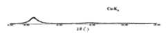
水素ガスとArガスの混合ガス中でCoNbZr合金をアーク溶解し、発生した微粒子を捕集した。合金微粒子の平均粒径は45nmであった。組成分析の結果合金微粒子の組成はCobal.Nb7Zr5(原子%)であった。X線回折を行った結果、図1に示すように合金微粒子はアモルファス特有のハローパターンを示しており、アモルファス合金微粒子であることが確認された。また、透過電子顕微鏡による観察の結果、結晶格子はほとんど観察されず、微粒子内部はアモルファス相がほとんどを占めていることが確認された。次に、このアモルファス合金微粒子をエアロゾル化チャンバー内でArガスと攪拌・混合してエアロゾル化し、成膜チャンバーとの圧力差によるガスの流れにより成膜チャンバーに搬送し、スリット状のノズルを通して加速、マスクを介して基板に噴射し、リング状のホトセラム基板上に外径13mm、内径10mm、厚さ5μmの厚膜からなる合金部材を製造した。作製した磁心を窒素ガス雰囲気の熱処理炉に挿入し、図2に示す熱処理パタ−ンで熱処理を行った。基板を取り除いた熱処理後のアモルファス合金部材のX線回折パターンを図3に示す。図3に示すように合金部材はアモルファス特有のハローパターンを示しておりアモルファス単相であることが確認された。また、透過電子顕微鏡観察の結果、図4に示すようにアモルファス単相であることが確認された。また、透過電子顕微鏡による観察の結果、結晶格子はほとんど観察されず、ほとんどがアモルファス相であることが確認された。次に熱処理後の合金部材の磁気特性を測定した。飽和磁束密度1.2T、保磁力56.8A/m、1MHzにおける品質係数Q=16.2の優れた特性が得られた。CoNbZr alloy was arc-melted in a mixed gas of hydrogen gas and Ar gas, and the generated fine particles were collected. The average particle diameter of the alloy fine particles was 45 nm. As a result of the composition analysis, the composition of the alloy fine particles was Cobal. Nb7 Zr5 (atomic%). As a result of X-ray diffraction, as shown in FIG. 1, the alloy fine particles showed a halo pattern peculiar to amorphous, and it was confirmed that they were amorphous alloy fine particles. As a result of observation with a transmission electron microscope, almost no crystal lattice was observed, and it was confirmed that the amorphous phase occupied most of the inside of the fine particles. Next, this amorphous alloy fine particle is agitated and mixed with Ar gas in the aerosolization chamber to be aerosolized, transferred to the film formation chamber by the gas flow due to the pressure difference with the film formation chamber, accelerated through the slit nozzle, An alloy member made of a thick film having an outer diameter of 13 mm, an inner diameter of 10 mm, and a thickness of 5 μm was manufactured on a ring-shaped photocellum substrate by spraying the substrate through a mask. The produced magnetic core was inserted into a heat treatment furnace in a nitrogen gas atmosphere, and heat treatment was performed with the heat treatment pattern shown in FIG. FIG. 3 shows an X-ray diffraction pattern of the amorphous alloy member after the heat treatment with the substrate removed. As shown in FIG. 3, the alloy member showed a halo pattern peculiar to amorphous, and was confirmed to be an amorphous single phase. Further, as a result of observation with a transmission electron microscope, it was confirmed to be an amorphous single phase as shown in FIG. Further, as a result of observation with a transmission electron microscope, almost no crystal lattice was observed, and it was confirmed that most were in an amorphous phase. Next, the magnetic properties of the alloy member after the heat treatment were measured. Excellent characteristics with a saturation magnetic flux density of 1.2 T, a coercive force of 56.8 A / m, and a quality factor Q = 16.2 at 1 MHz were obtained.
水アトマイズ法により平均粒径1μmのFebal.Ni37.3Mo3.2Si11.2B12.1合金粉末を作製した。次にこの粉末を400゜Cで1時間熱処理し脆化させた後、ミルにより粉砕・分級し1μmアンダーの合金微粒子を得た。X線回折の結果、アモルファス合金特有なハローパターンであり、結晶ピークは認められなかった。また、透過電子顕微鏡による観察の結果、結晶格子はほとんど観察されず、ほぼアモルファス相単相であることが確認された。次に、このアモルファス合金微粒子をエアロゾル化チャンバー内でArガスと攪拌・混合してエアロゾル化し、成膜チャンバーとの圧力差によるガスの流れにより成膜チャンバーに搬送し、スリット状のノズルを通して加速、マスクを介して基板に噴射し、リング状のSi基板上に外径13mm、内径10mm、厚さ8μmの厚膜からなる合金部材を製造した。作製した磁心を窒素ガス雰囲気の熱処理炉に挿入し、図2に示す熱処理パタ−ンで熱処理を行った。保持温度は400℃1時間とした。熱処理後の合金部材のX線回折を行った結果、アモルファス合金特有なハローパターンを示す。熱処理後の合金部材の磁気特性を測定した。飽和磁束密度0.80T、保磁力82.3 A/mの特性が得られた。また、基板からの剥離は認められなかった。Febal. Ni37.3 Mo3.2 Si11.2 B12.1 alloy powder having an average particle diameter of 1 μm was prepared by a water atomization method. Next, this powder was heat treated at 400 ° C. for 1 hour to be embrittled, and then pulverized and classified by a mill to obtain alloy fine particles of 1 μm under. As a result of X-ray diffraction, it was a halo pattern unique to an amorphous alloy, and no crystal peak was observed. Further, as a result of observation with a transmission electron microscope, almost no crystal lattice was observed, and it was confirmed that it was almost an amorphous phase single phase. Next, this amorphous alloy fine particle is agitated and mixed with Ar gas in the aerosolization chamber to be aerosolized, transferred to the film formation chamber by the gas flow due to the pressure difference with the film formation chamber, accelerated through the slit nozzle, An alloy member made of a thick film having an outer diameter of 13 mm, an inner diameter of 10 mm, and a thickness of 8 μm was manufactured on a ring-shaped Si substrate through a mask. The produced magnetic core was inserted into a heat treatment furnace in a nitrogen gas atmosphere, and heat treatment was performed with the heat treatment pattern shown in FIG. The holding temperature was 400 ° C. for 1 hour. As a result of X-ray diffraction of the alloy member after the heat treatment, a halo pattern peculiar to the amorphous alloy is shown. The magnetic properties of the alloy member after the heat treatment were measured. A saturation magnetic flux density of 0.80 T and a coercive force of 82.3 A / m were obtained. Further, no peeling from the substrate was observed.
ガスアトマイズ法により平均粒径35μmの合金粉末を得た。次にこの粉末を350゜Cで1時間熱処理し脆化させた後、ミルにより粉砕・分級し1μmアンダーの合金微粒子を得た。次にArガスと水素ガスを混合したガスを導入した高周波熱プラズマ装置のプラズマ発生部にこの合金微粒子を通過させ、溶融させ球状の表1に示す組成の合金微粒子を得た。X線回折の結果、アモルファス合金特有なハローパターンが認められた。また、透過電子顕微鏡による観察の結果、線分法で見積もった結晶相の体積分率が50%未満であることが確認された。このアモルファス合金微粒子をエアロゾル化チャンバー内でArガスと攪拌・混合してエアロゾル化し、成膜チャンバーとの圧力差によるガスの流れにより成膜チャンバーに搬送し、スリット状のノズルを通して加速、マスクを介して基板に噴射し、リング状のSi基板上に外径13mm、内径10mm、厚さ8μmの厚膜からなる合金部材を製造した。作製した磁心を窒素ガス雰囲気の熱処理炉に挿入し、図2に示す熱処理パタ−ンで熱処理を行った。保持温度は350℃とした。作製した厚膜の基板からの剥離は認められなかった。熱処理後の合金部材に5ターンの巻線を施しインダクタを作製した。次にこのインダクタの1MHzにおける特性を測定した。本発明インダクタ部品は高周波において高いQとインダクタンスが得られた。一方、表1の比較例に示すスパッタ法により作製した同一厚さの膜は、基板から一部が剥離した。 An alloy powder having an average particle size of 35 μm was obtained by gas atomization. Next, this powder was heat treated at 350 ° C. for 1 hour to be embrittled, and then pulverized and classified by a mill to obtain alloy fine particles of 1 μm under. Next, the alloy fine particles were passed through a plasma generating part of a high-frequency thermal plasma apparatus into which a mixed gas of Ar gas and hydrogen gas was introduced and melted to obtain spherical alloy fine particles having the composition shown in Table 1. As a result of X-ray diffraction, a halo pattern peculiar to amorphous alloys was recognized. As a result of observation with a transmission electron microscope, it was confirmed that the volume fraction of the crystal phase estimated by the line segment method was less than 50%. This amorphous alloy fine particle is agitated and mixed with Ar gas in the aerosolization chamber to form an aerosol, transported to the deposition chamber by the gas flow due to the pressure difference with the deposition chamber, accelerated through the slit-like nozzle, and through the mask An alloy member made of a thick film having an outer diameter of 13 mm, an inner diameter of 10 mm, and a thickness of 8 μm was manufactured on a ring-shaped Si substrate. The produced magnetic core was inserted into a heat treatment furnace in a nitrogen gas atmosphere, and heat treatment was performed with the heat treatment pattern shown in FIG. The holding temperature was 350 ° C. No peeling of the produced thick film from the substrate was observed. An inductor was manufactured by winding a 5-turn winding on the heat-treated alloy member. Next, the characteristics of this inductor at 1 MHz were measured. The inductor component of the present invention obtained high Q and inductance at high frequencies. On the other hand, a part of the film having the same thickness produced by the sputtering method shown in the comparative example of Table 1 was peeled off from the substrate.

ガスアトマイズ法により平均粒径35μmの合金粉末を得た。次にこの粉末を350゜Cで1時間熱処理し脆化させた後、ミルにより粉砕・分級し1μmアンダーの合金微粒子を得た。次にArガスと水素ガスを混合したガスを導入した高周波熱プラズマ装置のプラズマ発生部にこの合金微粒子を通過させ、溶融させ球状の表2に示す組成の合金微粒子を得た。X線回折の結果、アモルファス合金特有なハローパターンが認められた。また、透過電子顕微鏡による観察の結果、線分法で見積もった結晶相の体積分率が50%未満であることが確認された。また、アモルファス合金微粒子表面に酸化物層、窒化物層、フッ化物層を形成するため、酸素ガス、窒素ガスやフッ素ガスを装置に導入し微粒子表面に酸化物層、窒化物層、フッ化物層を形成した。合金微粒子の断面を透過電子顕微鏡により観察および表面分析した結果、厚さ6nmから30nmの酸化物層、窒化物層、フッ化物層が形成していることが確認された。このアモルファス合金微粒子をエアロゾル化チャンバー内でHeガスと攪拌・混合してエアロゾル化し、成膜チャンバーとの圧力差によるガスの流れにより成膜チャンバーに搬送し、スリット状のノズルを通して加速、マスクを介して基板に噴射し、リング状のガラス基板上に、厚さ18μmの厚膜からなる合金部材を製造した。作製した厚膜の基板からの剥離は認められなかった。作製した厚膜のX線回折の結果、アモルファス合金特有なハローパターンが認められた。また、透過電子顕微鏡による観察の結果、線分法で見積もった結晶相の体積分率が50%未満であることが確認された。次にこの厚膜の電気抵抗率を4探針法で測定した。得られた結果を表2に示す。また比較のために、酸素ガス、窒素ガスやフッ素ガスを装置に導入しない場合の電気抵抗率も示す。合金微粒子表面に酸化物層、窒化物層、フッ化物層を形成した方が高い電気抵抗率を示すことが確認された。また、溶液処理により合金微粒子表面に酸化物層、窒化物層、フッ化物層を形成しても作製したアモルファス合金部材の電気抵抗率が高くなることが確認された。 An alloy powder having an average particle size of 35 μm was obtained by gas atomization. Next, this powder was heat treated at 350 ° C. for 1 hour to be embrittled, and then pulverized and classified by a mill to obtain alloy fine particles of 1 μm under. Next, the alloy fine particles were passed through a plasma generating portion of a high-frequency thermal plasma apparatus into which a mixed gas of Ar gas and hydrogen gas was introduced and melted to obtain spherical alloy fine particles having the composition shown in Table 2. As a result of X-ray diffraction, a halo pattern peculiar to amorphous alloys was recognized. As a result of observation with a transmission electron microscope, it was confirmed that the volume fraction of the crystal phase estimated by the line segment method was less than 50%. Moreover, in order to form an oxide layer, nitride layer, and fluoride layer on the surface of the amorphous alloy fine particles, oxygen gas, nitrogen gas, or fluorine gas is introduced into the apparatus, and the oxide layer, nitride layer, fluoride layer is formed on the surface of the fine particles. Formed. As a result of observation and surface analysis of a cross section of the alloy fine particles with a transmission electron microscope, it was confirmed that an oxide layer, a nitride layer, and a fluoride layer having a thickness of 6 nm to 30 nm were formed. The amorphous alloy fine particles are agitated and mixed with He gas in the aerosolization chamber to be aerosolized, transported to the deposition chamber by the gas flow due to the pressure difference with the deposition chamber, accelerated through the slit-shaped nozzle, and passed through the mask. Then, an alloy member made of a thick film having a thickness of 18 μm was manufactured on a ring-shaped glass substrate. No peeling of the produced thick film from the substrate was observed. As a result of X-ray diffraction of the produced thick film, a halo pattern peculiar to an amorphous alloy was recognized. As a result of observation with a transmission electron microscope, it was confirmed that the volume fraction of the crystal phase estimated by the line segment method was less than 50%. Next, the electrical resistivity of this thick film was measured by a four-probe method. The obtained results are shown in Table 2. For comparison, the electrical resistivity when oxygen gas, nitrogen gas, and fluorine gas are not introduced into the apparatus is also shown. It was confirmed that an oxide layer, a nitride layer, and a fluoride layer formed on the surface of the alloy fine particles showed higher electrical resistivity. In addition, it was confirmed that the electrical resistivity of the produced amorphous alloy member was high even when an oxide layer, a nitride layer, and a fluoride layer were formed on the surface of the alloy fine particles by solution treatment.
ガスアトマイズ法により平均粒径35μmの表3に示す合金粉末を得た。次にこの粉末を350℃で1時間熱処理した後、ミルにより粉砕・分級し1μmアンダーの合金微粒子を得た。次にArガスと水素ガスを混合したガスを導入した高周波熱プラズマ装置のプラズマ発生部にこの合金微粒子を通過させ、溶融させ球状の表3に示す組成の合金微粒子を得た。X線回折を行った結果、図1に示すように合金微粒子はアモルファス特有のハローパターンを示しており、アモルファス合金微粒子であることが確認された。また、透過電子顕微鏡による観察の結果、結晶格子はほとんど観察されず、微粒子内部はアモルファス相がほとんどを占めていることが確認された。次に、このアモルファス合金微粒子をエアロゾル化チャンバー内でArガスと攪拌・混合してエアロゾル化し、成膜チャンバーとの圧力差によるガスの流れにより成膜チャンバーに搬送し、スリット状のノズルを通して加速、マスクを介して基板に噴射し、ガラス基板上に厚さ20μmの厚膜からなる合金部材を製造した。得られた厚膜についてX線回折を行った結果、アモルファス特有のハローパターンを示しており、アモルファス合金膜であることが確認された。また、透過電子顕微鏡による観察の結果、結晶格子はほとんど観察されず、厚膜内部はアモルファス相がほとんどを占めていることが確認された。次に、このアモルファス膜の熱分析を行い、ガラス遷移温度Tgと結晶化開始温度Txを測定し△Tx=Tx−Tgを求めた。得られた結果を表3に示す。ガラス遷移温度Tgが観測され、△Txも大きい金属ガラス厚膜が形成されていることが確認された。次に各試料をTg直上に昇温し、金属型を押しつけた。本発明アモルファス合金部材はきれいに型の転写可能であり、精密な形状の形成が可能であるためMEMSなどの小型部品に適していることが確認された。Alloy powders shown in Table 3 having an average particle diameter of 35 μm were obtained by gas atomization. Next, this powder was heat treated at 350 ° C. for 1 hour, and then pulverized and classified by a mill to obtain 1 μm-under alloy fine particles. Next, the alloy fine particles were passed through a plasma generation part of a high-frequency thermal plasma apparatus into which a mixed gas of Ar gas and hydrogen gas was introduced and melted to obtain spherical alloy fine particles having the composition shown in Table 3. As a result of X-ray diffraction, as shown in FIG. 1, the alloy fine particles showed a halo pattern peculiar to amorphous, and it was confirmed that they were amorphous alloy fine particles. As a result of observation with a transmission electron microscope, almost no crystal lattice was observed, and it was confirmed that the amorphous phase occupied most of the inside of the fine particles. Next, this amorphous alloy fine particle is agitated and mixed with Ar gas in the aerosolization chamber to be aerosolized, transferred to the film formation chamber by the gas flow due to the pressure difference with the film formation chamber, accelerated through the slit nozzle, It sprayed on the board | substrate through the mask and the alloy member which consists of a 20-micrometer-thick filmon a glass substrate was manufactured. As a result of performing X-ray diffraction on the obtained thick film, a halo pattern peculiar to amorphous was shown, and it was confirmed to be an amorphous alloy film. As a result of observation with a transmission electron microscope, almost no crystal lattice was observed, and it was confirmed that the amorphous phase occupied most of the thick film. Next, the amorphous film was subjected to thermal analysis, and the glass transition temperature Tg and the crystallization start temperature Tx were measured to obtain ΔTx = Tx−Tg. The obtained results are shown in Table 3. A glass transition temperature Tg was observed, and it was confirmed that a thick metal glass film having a large ΔTx was formed. Next, each sample was heated to just above Tg, and a metal mold was pressed. It has been confirmed that the amorphous alloy member of the present invention is suitable for small parts such as MEMS because the mold can be neatly transferred and a precise shape can be formed.
Claims (7)
Translated fromJapanesePriority Applications (1)
| Application Number | Priority Date | Filing Date | Title |
|---|---|---|---|
| JP2003295937AJP4392649B2 (en) | 2003-08-20 | 2003-08-20 | Amorphous alloy member, method for producing the same, and component using the same |
Applications Claiming Priority (1)
| Application Number | Priority Date | Filing Date | Title |
|---|---|---|---|
| JP2003295937AJP4392649B2 (en) | 2003-08-20 | 2003-08-20 | Amorphous alloy member, method for producing the same, and component using the same |
Publications (2)
| Publication Number | Publication Date |
|---|---|
| JP2005060805A JP2005060805A (en) | 2005-03-10 |
| JP4392649B2true JP4392649B2 (en) | 2010-01-06 |
Family
ID=34372001
Family Applications (1)
| Application Number | Title | Priority Date | Filing Date |
|---|---|---|---|
| JP2003295937AExpired - Fee RelatedJP4392649B2 (en) | 2003-08-20 | 2003-08-20 | Amorphous alloy member, method for producing the same, and component using the same |
Country Status (1)
| Country | Link |
|---|---|
| JP (1) | JP4392649B2 (en) |
Families Citing this family (28)
| Publication number | Priority date | Publication date | Assignee | Title |
|---|---|---|---|---|
| JP2007012999A (en)* | 2005-07-01 | 2007-01-18 | Sinto Brator Co Ltd | Magnetic core manufacturing method |
| NZ571099A (en) | 2006-03-20 | 2012-05-25 | Nippon Steel Corp | Hot dip galvannealed steel material having an zinc alloy plated layer containing at least 12% magnesium |
| JP5119465B2 (en) | 2006-07-19 | 2013-01-16 | 新日鐵住金株式会社 | Alloy having high amorphous forming ability and alloy plating metal material using the same |
| JP4868583B2 (en)* | 2006-09-04 | 2012-02-01 | Necトーキン株式会社 | Inductor and manufacturing method thereof |
| TWI434944B (en) | 2006-12-04 | 2014-04-21 | Amorphous alloy composition | |
| JP4678783B2 (en)* | 2006-12-06 | 2011-04-27 | Necトーキン株式会社 | Soft magnetic thick film and inductor using the same |
| EP1933337B8 (en)* | 2006-12-15 | 2010-09-01 | Alps Green Devices Co., Ltd | Fe-based amorphous magnetic alloy and magnetic sheet |
| WO2008129803A1 (en)* | 2007-03-20 | 2008-10-30 | Nec Tokin Corporation | Soft magnetic alloy, magnetic component using the same, and their production methods |
| BR122017017768B1 (en) | 2008-08-22 | 2021-02-17 | Tohoku Magnet Institute Co., Ltd. | alloy composition and method for forming an iron-based nanocrystalline alloy |
| JP5085470B2 (en)* | 2008-09-08 | 2012-11-28 | 株式会社東芝 | Core-shell magnetic material, device device, and antenna device. |
| JP5085471B2 (en) | 2008-09-08 | 2012-11-28 | 株式会社東芝 | Core-shell magnetic material, method for manufacturing core-shell magnetic material, device device, and antenna device. |
| JP5085595B2 (en)* | 2008-09-08 | 2012-11-28 | 株式会社東芝 | Core-shell magnetic material, method for manufacturing core-shell magnetic material, device device, and antenna device. |
| CN103352181B (en)* | 2013-05-31 | 2015-12-09 | 全椒君鸿软磁材料有限公司 | Si-Bi-Mn-Be system Fe-based amorphous alloy strip and preparation method thereof |
| CN103334068B (en)* | 2013-05-31 | 2016-02-17 | 全椒君鸿软磁材料有限公司 | Re-Be-Pb-Mg system Fe-based amorphous alloy strip and preparation method thereof |
| CN103668011B (en)* | 2013-12-05 | 2015-10-28 | 浙江大学 | The series bulk amorphous Alloy And Preparation Method of a kind of ZrCuAgAlBeNiCo |
| CN103695813B (en)* | 2013-12-19 | 2015-08-19 | 南京信息工程大学 | A kind of high saturation and magnetic intensity amorphous alloy material and preparation method thereof |
| CN107683512B (en)* | 2015-06-19 | 2019-11-26 | 株式会社村田制作所 | Magnetic powder and method for producing the same, magnetic core and method for producing the same, and coil component |
| CN105118604A (en)* | 2015-09-08 | 2015-12-02 | 杨雯雯 | Magnetic alloy material |
| CN106544603A (en)* | 2015-09-21 | 2017-03-29 | 南京理工大学 | A kind of cobalt base amorphous magnetically soft alloy of high-curie temperature and preparation method thereof |
| CN106205931A (en)* | 2016-08-22 | 2016-12-07 | 椤惧缓 | A kind of magnetic material and preparation method |
| CN106521365A (en)* | 2016-09-29 | 2017-03-22 | 宁波讯强电子科技有限公司 | Rare earth doped non-crystalline material for acoustic magnetic label resonance piece and preparation method thereof |
| CN109023159B (en)* | 2017-06-08 | 2020-02-21 | 比亚迪股份有限公司 | Copper-based amorphous alloy and its preparation method and mobile phone |
| IT201800007357A1 (en)* | 2018-07-19 | 2020-01-19 | Individual shielding device | |
| CN112342476B (en)* | 2020-10-21 | 2022-05-20 | 江苏大磁纳米材料有限公司 | Hydrogen-containing iron-based amorphous alloy and preparation method thereof |
| CN117099173A (en)* | 2021-03-25 | 2023-11-21 | 国立研究开发法人产业技术综合研究所 | Magnetic material for high frequency and method for producing the same |
| CN114574786B (en)* | 2022-03-11 | 2022-11-18 | 东莞理工学院 | Ternary amorphous alloy film and preparation method thereof |
| CN115608977A (en)* | 2022-12-16 | 2023-01-17 | 矿冶科技集团有限公司 | Iron-based amorphous powder for wear-resistant coating, preparation method of iron-based amorphous powder and wear-resistant amorphous coating |
| CN118685721B (en)* | 2024-06-04 | 2025-03-11 | 上海大学 | Preparation method of titanium-based high-entropy amorphous alloy with high thermal stability |
- 2003
- 2003-08-20JPJP2003295937Apatent/JP4392649B2/ennot_activeExpired - Fee Related
Also Published As
| Publication number | Publication date |
|---|---|
| JP2005060805A (en) | 2005-03-10 |
Similar Documents
| Publication | Publication Date | Title |
|---|---|---|
| JP4392649B2 (en) | Amorphous alloy member, method for producing the same, and component using the same | |
| US4985089A (en) | Fe-base soft magnetic alloy powder and magnetic core thereof and method of producing same | |
| JP5445889B2 (en) | Soft magnetic alloy, manufacturing method thereof, and magnetic component | |
| TWI626666B (en) | Soft magnetic alloy and magnetic parts | |
| TW201817897A (en) | Soft magnetic alloy and magnetic device | |
| JP6669304B2 (en) | Crystalline Fe-based alloy powder and method for producing the same | |
| TWI636143B (en) | Soft magnetic alloy and magnetic parts | |
| JP4210986B2 (en) | Magnetic alloy and magnetic parts using the same | |
| JP2009174034A (en) | Amorphous soft magnetic alloy, amorphous soft magnetic alloy strip, amorphous soft magnetic alloy powder, and magnetic core and magnetic component using the same | |
| JPH03219009A (en) | Production of fe-base soft-magnetic alloy | |
| JP5305126B2 (en) | Soft magnetic powder, method of manufacturing a dust core, dust core, and magnetic component | |
| JPWO2008133302A1 (en) | Soft magnetic ribbon, manufacturing method thereof, magnetic component, and amorphous ribbon | |
| CN110600218B (en) | Soft magnetic alloy and magnetic component | |
| WO2020026949A1 (en) | Soft magnetic powder, fe-based nano-crystal alloy powder, magnetic member, and dust core | |
| CN110033916B (en) | Soft magnetic alloy and magnetic component | |
| TWI667355B (en) | Soft magnetic alloy and magnetic parts | |
| JPWO2008133301A1 (en) | Soft magnetic alloy, manufacturing method thereof, and magnetic component | |
| TW201817896A (en) | Soft magnetic alloy and magnetic device | |
| TWI689599B (en) | Soft magnetic alloys and magnetic components | |
| JP2001001113A (en) | Alloy thin strip, member using it, and its manufacture | |
| JP2018123360A (en) | Soft magnetic alloy and magnetic component | |
| CN111566243A (en) | Soft magnetic alloy thin strip and magnetic component | |
| EP3511959B1 (en) | Soft magnetic alloy and magnetic device | |
| JP2000328206A (en) | Soft magnetic alloy strip and magnetic core using the same, its apparatus and production | |
| JP5170776B2 (en) | Soft magnetic material |
Legal Events
| Date | Code | Title | Description |
|---|---|---|---|
| A621 | Written request for application examination | Free format text:JAPANESE INTERMEDIATE CODE: A621 Effective date:20060711 | |
| A977 | Report on retrieval | Free format text:JAPANESE INTERMEDIATE CODE: A971007 Effective date:20090318 | |
| A131 | Notification of reasons for refusal | Free format text:JAPANESE INTERMEDIATE CODE: A131 Effective date:20090619 | |
| A521 | Written amendment | Free format text:JAPANESE INTERMEDIATE CODE: A523 Effective date:20090803 | |
| TRDD | Decision of grant or rejection written | ||
| A01 | Written decision to grant a patent or to grant a registration (utility model) | Free format text:JAPANESE INTERMEDIATE CODE: A01 Effective date:20090918 | |
| A01 | Written decision to grant a patent or to grant a registration (utility model) | Free format text:JAPANESE INTERMEDIATE CODE: A01 | |
| A61 | First payment of annual fees (during grant procedure) | Free format text:JAPANESE INTERMEDIATE CODE: A61 Effective date:20091001 | |
| R150 | Certificate of patent or registration of utility model | Free format text:JAPANESE INTERMEDIATE CODE: R150 | |
| FPAY | Renewal fee payment (event date is renewal date of database) | Free format text:PAYMENT UNTIL: 20121023 Year of fee payment:3 | |
| FPAY | Renewal fee payment (event date is renewal date of database) | Free format text:PAYMENT UNTIL: 20121023 Year of fee payment:3 | |
| FPAY | Renewal fee payment (event date is renewal date of database) | Free format text:PAYMENT UNTIL: 20131023 Year of fee payment:4 | |
| LAPS | Cancellation because of no payment of annual fees |