JP4392441B2 - Luminous panel assembly - Google Patents
Luminous panel assemblyDownload PDFInfo
- Publication number
- JP4392441B2 JP4392441B2JP2007227063AJP2007227063AJP4392441B2JP 4392441 B2JP4392441 B2JP 4392441B2JP 2007227063 AJP2007227063 AJP 2007227063AJP 2007227063 AJP2007227063 AJP 2007227063AJP 4392441 B2JP4392441 B2JP 4392441B2
- Authority
- JP
- Japan
- Prior art keywords
- light
- panel member
- light emitting
- panel
- assembly
- Prior art date
- Legal status (The legal status is an assumption and is not a legal conclusion. Google has not performed a legal analysis and makes no representation as to the accuracy of the status listed.)
- Expired - Fee Related
Links
Images


Classifications
- G—PHYSICS
- G02—OPTICS
- G02B—OPTICAL ELEMENTS, SYSTEMS OR APPARATUS
- G02B6/00—Light guides; Structural details of arrangements comprising light guides and other optical elements, e.g. couplings
- G02B6/0001—Light guides; Structural details of arrangements comprising light guides and other optical elements, e.g. couplings specially adapted for lighting devices or systems
- G02B6/0011—Light guides; Structural details of arrangements comprising light guides and other optical elements, e.g. couplings specially adapted for lighting devices or systems the light guides being planar or of plate-like form
- G02B6/0013—Means for improving the coupling-in of light from the light source into the light guide
- G02B6/0015—Means for improving the coupling-in of light from the light source into the light guide provided on the surface of the light guide or in the bulk of it
- G02B6/002—Means for improving the coupling-in of light from the light source into the light guide provided on the surface of the light guide or in the bulk of it by shaping at least a portion of the light guide, e.g. with collimating, focussing or diverging surfaces
- G02B6/0021—Means for improving the coupling-in of light from the light source into the light guide provided on the surface of the light guide or in the bulk of it by shaping at least a portion of the light guide, e.g. with collimating, focussing or diverging surfaces for housing at least a part of the light source, e.g. by forming holes or recesses
- G—PHYSICS
- G02—OPTICS
- G02B—OPTICAL ELEMENTS, SYSTEMS OR APPARATUS
- G02B6/00—Light guides; Structural details of arrangements comprising light guides and other optical elements, e.g. couplings
- G02B6/0001—Light guides; Structural details of arrangements comprising light guides and other optical elements, e.g. couplings specially adapted for lighting devices or systems
- G02B6/0011—Light guides; Structural details of arrangements comprising light guides and other optical elements, e.g. couplings specially adapted for lighting devices or systems the light guides being planar or of plate-like form
- G02B6/0013—Means for improving the coupling-in of light from the light source into the light guide
- G02B6/0015—Means for improving the coupling-in of light from the light source into the light guide provided on the surface of the light guide or in the bulk of it
- G02B6/0018—Redirecting means on the surface of the light guide
- G—PHYSICS
- G02—OPTICS
- G02B—OPTICAL ELEMENTS, SYSTEMS OR APPARATUS
- G02B6/00—Light guides; Structural details of arrangements comprising light guides and other optical elements, e.g. couplings
- G02B6/0001—Light guides; Structural details of arrangements comprising light guides and other optical elements, e.g. couplings specially adapted for lighting devices or systems
- G02B6/0011—Light guides; Structural details of arrangements comprising light guides and other optical elements, e.g. couplings specially adapted for lighting devices or systems the light guides being planar or of plate-like form
- G02B6/0033—Means for improving the coupling-out of light from the light guide
- G02B6/0035—Means for improving the coupling-out of light from the light guide provided on the surface of the light guide or in the bulk of it
- G02B6/0036—2-D arrangement of prisms, protrusions, indentations or roughened surfaces
- G—PHYSICS
- G02—OPTICS
- G02B—OPTICAL ELEMENTS, SYSTEMS OR APPARATUS
- G02B6/00—Light guides; Structural details of arrangements comprising light guides and other optical elements, e.g. couplings
- G02B6/0001—Light guides; Structural details of arrangements comprising light guides and other optical elements, e.g. couplings specially adapted for lighting devices or systems
- G02B6/0011—Light guides; Structural details of arrangements comprising light guides and other optical elements, e.g. couplings specially adapted for lighting devices or systems the light guides being planar or of plate-like form
- G02B6/0033—Means for improving the coupling-out of light from the light guide
- G02B6/0035—Means for improving the coupling-out of light from the light guide provided on the surface of the light guide or in the bulk of it
- G02B6/0038—Linear indentations or grooves, e.g. arc-shaped grooves or meandering grooves, extending over the full length or width of the light guide
- G—PHYSICS
- G02—OPTICS
- G02B—OPTICAL ELEMENTS, SYSTEMS OR APPARATUS
- G02B6/00—Light guides; Structural details of arrangements comprising light guides and other optical elements, e.g. couplings
- G02B6/0001—Light guides; Structural details of arrangements comprising light guides and other optical elements, e.g. couplings specially adapted for lighting devices or systems
- G02B6/0011—Light guides; Structural details of arrangements comprising light guides and other optical elements, e.g. couplings specially adapted for lighting devices or systems the light guides being planar or of plate-like form
- G02B6/0066—Light guides; Structural details of arrangements comprising light guides and other optical elements, e.g. couplings specially adapted for lighting devices or systems the light guides being planar or of plate-like form characterised by the light source being coupled to the light guide
- G02B6/0068—Arrangements of plural sources, e.g. multi-colour light sources
- A—HUMAN NECESSITIES
- A61—MEDICAL OR VETERINARY SCIENCE; HYGIENE
- A61B—DIAGNOSIS; SURGERY; IDENTIFICATION
- A61B90/00—Instruments, implements or accessories specially adapted for surgery or diagnosis and not covered by any of the groups A61B1/00 - A61B50/00, e.g. for luxation treatment or for protecting wound edges
- A61B90/30—Devices for illuminating a surgical field, the devices having an interrelation with other surgical devices or with a surgical procedure
- A61B2090/309—Devices for illuminating a surgical field, the devices having an interrelation with other surgical devices or with a surgical procedure using white LEDs
- G—PHYSICS
- G02—OPTICS
- G02B—OPTICAL ELEMENTS, SYSTEMS OR APPARATUS
- G02B6/00—Light guides; Structural details of arrangements comprising light guides and other optical elements, e.g. couplings
- G02B6/0001—Light guides; Structural details of arrangements comprising light guides and other optical elements, e.g. couplings specially adapted for lighting devices or systems
- G02B6/0011—Light guides; Structural details of arrangements comprising light guides and other optical elements, e.g. couplings specially adapted for lighting devices or systems the light guides being planar or of plate-like form
- G02B6/0013—Means for improving the coupling-in of light from the light source into the light guide
- G02B6/0023—Means for improving the coupling-in of light from the light source into the light guide provided by one optical element, or plurality thereof, placed between the light guide and the light source, or around the light source
- G02B6/0028—Light guide, e.g. taper
- G—PHYSICS
- G02—OPTICS
- G02B—OPTICAL ELEMENTS, SYSTEMS OR APPARATUS
- G02B6/00—Light guides; Structural details of arrangements comprising light guides and other optical elements, e.g. couplings
- G02B6/0001—Light guides; Structural details of arrangements comprising light guides and other optical elements, e.g. couplings specially adapted for lighting devices or systems
- G02B6/0011—Light guides; Structural details of arrangements comprising light guides and other optical elements, e.g. couplings specially adapted for lighting devices or systems the light guides being planar or of plate-like form
- G02B6/0013—Means for improving the coupling-in of light from the light source into the light guide
- G02B6/0023—Means for improving the coupling-in of light from the light source into the light guide provided by one optical element, or plurality thereof, placed between the light guide and the light source, or around the light source
- G02B6/0031—Reflecting element, sheet or layer
- G—PHYSICS
- G02—OPTICS
- G02B—OPTICAL ELEMENTS, SYSTEMS OR APPARATUS
- G02B6/00—Light guides; Structural details of arrangements comprising light guides and other optical elements, e.g. couplings
- G02B6/0001—Light guides; Structural details of arrangements comprising light guides and other optical elements, e.g. couplings specially adapted for lighting devices or systems
- G02B6/0011—Light guides; Structural details of arrangements comprising light guides and other optical elements, e.g. couplings specially adapted for lighting devices or systems the light guides being planar or of plate-like form
- G02B6/0033—Means for improving the coupling-out of light from the light guide
- G02B6/0035—Means for improving the coupling-out of light from the light guide provided on the surface of the light guide or in the bulk of it
- G02B6/004—Scattering dots or dot-like elements, e.g. microbeads, scattering particles, nanoparticles
- G02B6/0043—Scattering dots or dot-like elements, e.g. microbeads, scattering particles, nanoparticles provided on the surface of the light guide
- H—ELECTRICITY
- H01—ELECTRIC ELEMENTS
- H01H—ELECTRIC SWITCHES; RELAYS; SELECTORS; EMERGENCY PROTECTIVE DEVICES
- H01H2219/00—Legends
- H01H2219/054—Optical elements
- H01H2219/062—Light conductor
- H—ELECTRICITY
- H01—ELECTRIC ELEMENTS
- H01H—ELECTRIC SWITCHES; RELAYS; SELECTORS; EMERGENCY PROTECTIVE DEVICES
- H01H2221/00—Actuators
- H01H2221/07—Actuators transparent
- Y—GENERAL TAGGING OF NEW TECHNOLOGICAL DEVELOPMENTS; GENERAL TAGGING OF CROSS-SECTIONAL TECHNOLOGIES SPANNING OVER SEVERAL SECTIONS OF THE IPC; TECHNICAL SUBJECTS COVERED BY FORMER USPC CROSS-REFERENCE ART COLLECTIONS [XRACs] AND DIGESTS
- Y10—TECHNICAL SUBJECTS COVERED BY FORMER USPC
- Y10S—TECHNICAL SUBJECTS COVERED BY FORMER USPC CROSS-REFERENCE ART COLLECTIONS [XRACs] AND DIGESTS
- Y10S362/00—Illumination
- Y10S362/80—Light emitting diode
Landscapes
- Physics & Mathematics (AREA)
- General Physics & Mathematics (AREA)
- Optics & Photonics (AREA)
- Planar Illumination Modules (AREA)
- Light Guides In General And Applications Therefor (AREA)
- Liquid Crystal (AREA)
Description
Translated fromJapanese本発明は一般に、発光パネルアセンブリに関する。該発光パネルアセンブリは効果的に光を導く透明パネル部材を備え、該透明パネル部材によって導かれる光が1つ以上の光放出領域からその長さに沿って照射されるように制御する。 The present invention generally relates to light emitting panel assemblies. The light emitting panel assembly includes a transparent panel member that effectively guides light, and controls the light guided by the transparent panel member to be irradiated along its length from one or more light emitting areas.
発光パネルアセンブリは一般に公知である。しかしながら本発明は、該パネルアセンブリから放出される光をよりよく制御し、光をより効率的に利用することによって、より多くの光がパネルアセンブリから放出されるようにするいくつかの異なる発光パネルアセンブリの構成に関する。 Light emitting panel assemblies are generally known. However, the present invention provides several different light emitting panels that allow more light to be emitted from the panel assembly by better controlling the light emitted from the panel assembly and making more efficient use of the light. It relates to the structure of the assembly.
本発明のある局面によると、発光パネルアセンブリは、光遷移領域を有する発光パネル部材を有する。該光遷移領域においては、少なくとも1つの光源が適切に取り付けられ、光をパネル部材の光入力表面に伝える。 According to an aspect of the present invention, the light emitting panel assembly includes a light emitting panel member having a light transition region. In the light transition region, at least one light source is suitably mounted to transmit light to the light input surface of the panel member.
本発明の他の局面によると、望ましくは光源は光遷移領域に埋め込まれるか、はめ込まれるか、または接着され、光源と光遷移領域との間におけるいかなるエアーギャップも排除し、表面反射を軽減し、および/またはいかなるレンズ効果も排除する。これにより、光の損失を軽減しパネルアセンブリから放出される光を増加させる。 According to another aspect of the invention, preferably the light source is embedded, fitted or glued into the light transition region, eliminating any air gap between the light source and the light transition region, reducing surface reflections. And / or eliminate any lens effects. This reduces light loss and increases the light emitted from the panel assembly.
本発明のさらに他の局面によると、光源から照射される光の一部の経路を変化させるパネルアセンブリは反射表面または屈折表面を有し得る。なぜなら、光の経路は通常、光がパネル部材内により長時間滞在しおよび/またはパネル部材の効率が向上するような許容できる角度ではパネル部材には入射しないからである。 According to yet another aspect of the present invention, the panel assembly that changes the path of a portion of the light emitted from the light source may have a reflective or refractive surface. This is because the light path typically does not enter the panel member at an acceptable angle such that the light stays longer in the panel member and / or improves the efficiency of the panel member.
本発明のさらに他の局面によると、パネル部材の1つ以上の光放出領域からの光の一部の屈折角度を変えることによって、パネル部材から所望の光放出分布が提供されるようにする発光パネル部材は、光抽出変形部(lightextractingdeformities)または分裂部(disruptions)のパターンを有する。 According to yet another aspect of the invention, light emission that provides a desired light emission distribution from the panel member by changing the refraction angle of a portion of the light from one or more light emitting regions of the panel member. The panel member has a pattern of light extraction deformities or disruptions.
本発明のさらに他の局面によると、光源は多数の着色光源を有し得、1つ以上の光放出領域に光を供給し、着色または白色光放出分布を提供する。 According to yet another aspect of the invention, the light source can have a number of colored light sources that provide light to one or more light emitting regions to provide a colored or white light emitting distribution.
本発明のさらに他の局面によると、パネルアセンブリはパネル部材に光が入射する前に複数の着色光を混合するための遷移領域を有し、これにより所望の着色または白色光放出分布を生成する。 According to yet another aspect of the invention, the panel assembly has a transition region for mixing a plurality of colored lights before the light is incident on the panel member, thereby producing a desired colored or white light emission distribution. .
上述の関連する目的を達成するために、本発明は以下に完全に説明されかつ特にクレームに指摘される特徴を包含する。本発明の実施態様を詳細に示す以下の説明および添付の図面は本発明を示すものであるが、本発明の原則が採用され得るさまざまな形態のうちのいくつかを示すものでもある。 To the accomplishment of the related objectives described above, the present invention encompasses the features fully described below and particularly pointed out in the claims. The following description and the annexed drawings detailing embodiments of the invention illustrate the invention, but also illustrate some of the various forms in which the principles of the invention may be employed.
本発明のさまざまな発光パネルアセンブリは非常に効果的なパネルアセンブリであり、少ない電力消費で、より均一でかつより多くの光をパネル部材から放出するために使用され得る。また、本発明によると、パネル部材をより薄くおよび/または長く、および/またはさまざまな形状および大きさに形成することが可能である。 The various light emitting panel assemblies of the present invention are highly effective panel assemblies and can be used to emit more uniform and more light from the panel members with less power consumption. Also, according to the present invention, the panel member can be made thinner and / or longer and / or various shapes and sizes.
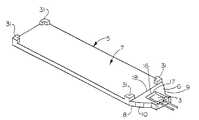
ここで、図を参照しながら本発明を説明する。まず図1を参照すると、本発明による発光パネルアセンブリ1の1つの形状が模式的に示されている。該発光パネルアセンブリ1は、透明発光パネル2および1つ以上の光源3を有する。該1つ以上の光源3は、当該分野において知られているように、光源3から発光パネル2への遷移を行うために使用される光遷移部材または領域4に所定のパターンの光を照射する。光遷移領域4によって透明発光パネル2へと伝えられる光は、所望のようにパネルの全長に沿って、またはパネルの長さに沿って1つ以上の光放出領域から照射され得、特定の用途に適合する所望の光放出分布を生成する。 The present invention will now be described with reference to the drawings. Referring first to FIG. 1, one shape of a light emitting panel assembly 1 according to the present invention is schematically shown. The light emitting panel assembly 1 has a transparent light emitting panel 2 and one or
図1において、光遷移領域4は、発光パネル2の一端と一体化した延長部として示されており、ほぼ長方形である。しかしながら、光遷移領域4は光源を埋め込むか、はめ込むか、接着するか、または他の方法によって取り付けるのに適切な他の形状でもあり得る。また、効率を向上させるために、反射表面または屈折表面が備えられ得る。さらに、光遷移領域4は所望であれば、パネル部材の光入力表面13に適切に取り付けられている独立した部品であり得る。また、光源から発光パネルを通って許容できる角度で照射される光の一部をより効率的に反射または屈折させるために、光遷移領域の側面は湾曲し得る。 In FIG. 1, the light transition region 4 is shown as an extension unit integrated with one end of the light emitting panel 2 and is substantially rectangular. However, the light transition region 4 can also be other shapes suitable for embedding, fitting, gluing or otherwise attaching the light source. Also, reflective or refractive surfaces can be provided to improve efficiency. Further, the light transition region 4 can be a separate component that is suitably attached to the light input surface 13 of the panel member, if desired. Also, the side surfaces of the light transition region can be curved in order to more efficiently reflect or refract part of the light emitted from the light source through the light emitting panel at an acceptable angle.
図2は本発明による発光パネルアセンブリ5の他の形状を示す。発光パネル7の一端には、パネル光遷移領域6が備えられている。パネル光遷移領域6は、光源3の周りおよび後ろに位置する側面8および9を有し、側面8および9は光源3から照射される光をより効率的に反射および/または屈折および集束させるような形状となっている。光はこれらの表面に当たって許容できる角度で光遷移領域6に戻り、発光パネル7の一端にある光入力表面18に入射する。また、図1および図2のパネルアセンブリ1および5の光遷移領域4および6の側面の一部には、適切な反射性材料またはコーティング10が設けられ得る。反射性材料またはコーティング10に光の一部が当たって光量を最大にするかさもなければ光遷移領域4または6に反射して戻され発光パネル2または7に入射する光を変化させる。 FIG. 2 shows another shape of the light
図1および図2に示されるパネルアセンブリ1および5は単一の光源3を備えるが、図3は、本発明による2つの光源3を備える発光パネルアセンブリ11を示す。当然ながら、本発明のパネルアセンブリは、特定の用途に応じて所望されるように、いかなる数の光源でも備えられ得ると理解される。 Although the panel assemblies 1 and 5 shown in FIGS. 1 and 2 comprise a
図3のパネルアセンブリ11は、発光パネル14の一端に光遷移領域12を備える。発光パネル14は、各光源3の周りおよび後ろに反射表面および/または屈折表面15を有する。これらの表面15は、例えば、湾曲、直線、および/または切り子面表面などの適切な形状とされ得、所望であれば、これらの表面の一部には適切な反射性材料またはコーティングが設けられ得て、例えば360°のパターンで光を照射する白熱光源から光遷移領域12を通って照射される光の一部をより効率的に発光パネル14の光入力表面19へと反射および/または屈折および集束させる。 The panel assembly 11 of FIG. 3 includes a
スロット、キャビティ、または開口部16は、機械加工、金型成形、またはその他の方法によってパネルアセンブリ11の光遷移領域12に形成され、光源3が何らかの適切な方法で該スロット、キャビティ、または開口部16に機械的に保持され得る。しかしながら、好ましくは光源3は光遷移領域に埋め込まれるか、はめ込まれるか、または接着されて、光源と周辺の光遷移領域との間のいかなるエアーギャップまたは空気界面をも排除することによって、光の損失を軽減し発光パネルによって照射される光放出を増加させる。光源のこのような取り付けは、例えば、十分な量の適切な埋め込み、はめ込みまたは接着材料17を使用して、光遷移領域12のスロット、キャビティ、または開口部16に光源3を接着することによって達成され得る。スロット、キャビティ、または開口部16は光遷移領域12の上部、底部、側面または後部に位置し得る。接着もまた、追加材料を使用することのないさまざまな方法、例えば熱接着、加熱ステーキング(heatstaking)、超音波溶接または可塑溶接(plasticwelding)などによって達成され得る。他の接着方法としては、光源周囲へのインサート成形および注型などがある。 Slots, cavities, or
発光パネルには、例えばアクリル製またはポリカーボネート製などのいかなる適切なタイプの透明発光材料も使用し得る。また、パネルは実質的に平面または湾曲であり得、単一または多層であり得、そしてさまざまな厚さおよび形状であり得る。さらに、パネルは柔軟または硬質であり得、また、さまざまな構成要素から構成され得る。さらに、パネルは中空で、液体、空気、または固体で充填され得、そして穴または隆起(ridge)を有し得る。 Any suitable type of transparent luminescent material may be used for the luminescent panel, for example made of acrylic or polycarbonate. Also, the panels can be substantially planar or curved, can be single or multilayer, and can be of various thicknesses and shapes. Further, the panels can be flexible or rigid and can be composed of various components. Further, the panels are hollow, can be filled with liquid, air, or solid and can have holes or ridges.
各光源3もまた、いかなる適切なタイプでもあり得、例えば、本願と同じ譲受人によって譲渡されその全体が本願において参考のため援用される、米国特許第4,897,771号または5,005,108号に開示されるようないかなるタイプでもあり得る。特に光源3は、アーク灯、着色されるかフィルタが付けられるかまたは塗装されてもよい白熱電球、レンズ端電球、線光源、ハロゲンランプ、発光ダイオード(LED)、LEDからのチップ、ネオン管、蛍光管、遠隔光源から延びる光ファイバ光導体、レーザーまたはレーザーダイオード、または他のいかなる適切な光源でもあり得る。さらに光源3は、所望の着色または白色光放出分布を提供するために、多色LEDまたは多数の着色照射光源の組み合わせでもあり得る。例えば、異なる色のLEDのような複数の着色灯(赤、青、緑)または多数の着色チップを有する単一のLEDを使用し、各着色光の強度を変化させることによって、白色光またはいかなる他の着色光放出分布も生成し得る。 Each
所望に応じて、パネル部材の一方または両方の側面、もしくはパネル部材の一方または両方の側面の1つ以上の選択された領域に光抽出変形部または分裂部のパターンが設けられ得る。図4aは、このような光表面領域20の1つを模式的に示す。光表面領域20上には、光抽出変形部または分裂部21のパターンが設けられている。本願で使用される用語「変形部(deformity)」または「分裂部(disruption)」は区別無く使用され、光の一部を照射させる、パネル表面および/またはコーティングまたは表面処理の形状または幾何学的形態におけるいかなる変化も意味する。図4aに示される光抽出変形部21のパターンは、光線の一部の反射の内側角度が十分に大きくなり、光抽出変形部21が設けられている一方または両方の側面を通って光線がパネルから照射されるか、またはパネルを通って反射し返され他方の側面から照射されるように光線を分解する、可変のパターンを含む。 If desired, a pattern of light extraction deformations or splits may be provided on one or both sides of the panel member, or on one or more selected areas on one or both sides of the panel member. FIG. 4 a schematically shows one such
これらの変形部または分裂部21はさまざまな方法によって形成され得、例えば、塗装されたパターン、エッチングされたパターン、機械加工されたパターン、印刷されたパターン、加熱プレスされたパターン、または金型成形されたパターンなどをパネル部材の選択された光放出領域に設けることによって形成される。例えばパッド印刷(padprinting)、シルクスクリーン、インクジェット、熱転写フィルム加工などによってインクまたは印刷パターンを付与し得る。変形部はまた、パネル部材に変形部を付与するために使用されるシートまたはフィルム上に印刷され得る。このシートまたはフィルムは、図3および図5に示されるシートまたはフィルム27のように、例えばシートまたはフィルムをパネル部材の一方または両方の側面に対して接着または他の方法で配置することによって、光パネルアセンブリの永久部品となって、所望の効果を達成し得る。 These deformations or splits 21 can be formed by various methods, for example, a painted pattern, an etched pattern, a machined pattern, a printed pattern, a hot pressed pattern, or a mold The pattern is formed in a selected light emission region of the panel member. For example, the ink or print pattern may be applied by pad printing, silk screen, ink jet, thermal transfer film processing, and the like. The deformation can also be printed on a sheet or film used to impart the deformation to the panel member. This sheet or film can be made of light, for example by adhering or otherwise placing the sheet or film against one or both sides of the panel member, such as the sheet or
パネル領域上で変形部21の密度、不透明性または透光性、形状、深度、色、面積、屈折率またはタイプを変化させることによって、パネルの光放出を制御し得る。変形部または分裂部は、パネルのどの領域から照射される光のパーセンテージも制御するために使用され得る。例えば少量の光放出が所望とされるパネル領域には、少量および/または小さいサイズの変形部21が配置され得る。反対に、大量の光放出が所望とされるパネル領域には、大きなパーセンテージおよび/または大きさの大きい変形部21が配置され得る。 The light emission of the panel can be controlled by changing the density, opacity or translucency, shape, depth, color, area, refractive index or type of the deformation 21 on the panel region. The deformation or split can be used to control the percentage of light emitted from any area of the panel. For example, in a panel region where a small amount of light emission is desired, a small and / or small size deformation 21 may be arranged. Conversely, large percentages and / or large deformations 21 can be placed in panel areas where a large amount of light emission is desired.
均一な光放出分布を提供するためには、パネルのさまざまな領域において、変形部のパーセンテージおよび/または大きさを変化させることが必要である。例えば、パネルを進行する光の量は通常、光源に近い領域の方が、光源からより遠い他の領域よりも多い。光抽出変形部21のパターンは、例えば光源3から離れた距離により高い密度の光抽出変形部を提供することによって、パネル部材内における光分散(variance)を調整するために使用され得る。これにより、発光パネルからより均一な光放出分布が提供される。 In order to provide a uniform light emission distribution, it is necessary to vary the percentage and / or size of the deformations in various regions of the panel. For example, the amount of light traveling through the panel is usually greater in the area closer to the light source than in other areas farther from the light source. The pattern of the light extraction deformation 21 can be used to adjust the light dispersion in the panel member, for example by providing a higher density light extraction deformation at a distance away from the
変形部21はまた、特定の用途に適合するように、照射される光の放出光線角度分布を制御するために使用され得る。例えば、パネルアセンブリが液晶表示装置のバックライトを提供するために使用される場合、変形部21が光線を所定の光線角度でパネルから照射させ、小さい損失で液晶表示装置を通過するようにすると、光放出はより効果的となる。 The deformation 21 can also be used to control the emitted light beam angular distribution of the irradiated light to suit a particular application. For example, when the panel assembly is used to provide a backlight of a liquid crystal display device, if the deforming portion 21 irradiates light from the panel at a predetermined light beam angle and passes through the liquid crystal display device with a small loss, Light emission becomes more effective.
さらに光抽出変形部のパターンは、パネル部材の光抽出による光放出分散を調整するために使用され得る。光抽出変形部21のパターンは、塗料、インク、コーティング、エポキシ樹脂などの、光沢を有するものから光沢のないものの範囲のいずれかまたは両方の広いスペクトルを利用して光放出領域上に印刷され得る。また、変形部21の到達範囲を変化させるために、光抽出変形部21のパターンには中間調分離技術(half-toneseparationtechniques)が使用され得る。さらに、光抽出変形部21のパターンは多層であり得るかまたは屈折率で変化し得る。 Furthermore, the pattern of the light extraction deformation part can be used to adjust the light emission dispersion due to the light extraction of the panel member. The pattern of the light extraction deformation portion 21 can be printed on the light emission region using a wide spectrum of paint, ink, coating, epoxy resin, etc., either glossy to matte or both. . Also, half-tone separation techniques can be used for the pattern of the light extraction deformation unit 21 in order to change the reach of the deformation unit 21. Furthermore, the pattern of the light extraction deformation part 21 may be multilayer or may change with the refractive index.
光抽出変形部21の印刷パターンは、点、正方形、ダイアモンド形、楕円形、星形、不規則な形状などに形状が変化し得、望ましくは1つの変形部/素子につき0.006平方インチ以下であり得る。また、望ましくは1インチにつき60本の線またはより繊細な印刷パターンが使用され得、これにより、特定の用途において印刷パターン中の変形部または形状21がほとんど人間の目に見えなくなるため、より大きな素子を使用する光抽出パターンに対して通常行われる階調度または帯域ライン(bandinglines)の検出が不要となる。さらに、変形部はパネル部材の長さおよび/または幅に沿って形状および/または大きさが変化し得る。また、変形部の不規則な配置パターンが、パネル部材の長さおよび/または幅に渡って使用され得る。変形部は、干渉縞(moire)または他の妨害効果を減少させるために、特定の角度を有しない形状またはパターンを有し得る。これらの不規則パターンを形成する方法の例としては、確率的(stochastic)印刷パターン技術を使用するパターン形状、周波数変調中間調パターン、またはランダムドット中間調の印刷がある。さらに、パネル部材における色補正を行うために、変形部は着色され得る。変形部の色はまた、例えばさまざまな色を同じまたは異なる光放出領域に設けるために、パネル部材にわたって変化し得る。 The printed pattern of the light extraction deformable portion 21 can change in shape to dots, squares, diamonds, ellipses, stars, irregular shapes, etc., preferably 0.006 square inches or less per deformable portion / element obtain. Also, desirably 60 lines per inch or a finer printed pattern can be used, which makes larger deformations or shapes 21 in the printed pattern less visible to the human eye in certain applications. It is not necessary to detect gradation levels or banding lines that are normally performed on light extraction patterns that use elements. Further, the deformed portion may change in shape and / or size along the length and / or width of the panel member. Also, an irregular arrangement pattern of deformations can be used across the length and / or width of the panel member. The deformation may have a shape or pattern that does not have a specific angle to reduce moire or other disturbing effects. Examples of methods for forming these irregular patterns include pattern shapes, stochastic printing pattern techniques, frequency modulated halftone patterns, or random dot halftone printing. Furthermore, in order to perform color correction in the panel member, the deformed portion can be colored. The color of the deformation may also vary across the panel member, for example to provide different colors in the same or different light emitting areas.
図4aに示される光抽出パターン21につけ加えるかまたはその代わりに、金型パターンのより複雑な形状を使用したプリズム表面、くぼんだまたは隆起した表面などの他の光抽出変形部が、パネル部材の1つ以上の領域中または上に、金型成形、エッチング、スタンピング、熱成形、加熱プレス加工(hotstamped)などで形成され得る。図4bおよび図4cはプリズム表面23または凹部24が形成されたパネル領域22を示す。図4dは、パネル領域外に形成されたプリズム表面または他の反射表面または屈折表面25を示す。該プリズム表面、くぼんだ表面、または隆起した表面は、光線の一部と接触してパネル部材から照射させる。また、プリズム、凹部または他の表面は、異なる方向に光を向かわせて所望の光放出分布または効果を生み出すために変化され得る。さらに、反射表面または屈折表面は、干渉縞(moire)または他の妨害効果を減少させるために、特定の角度を有しない形状またはパターンを有し得る。 In addition to or instead of the light extraction pattern 21 shown in FIG. 4a, other light extraction deformations, such as prism surfaces, recessed or raised surfaces using more complex shapes of the mold pattern, may be included in the panel member. It can be formed in or on one or more areas by mold forming, etching, stamping, thermoforming, hotstamped, and the like. 4b and 4c show a
図5の断面図に最もよく見られるように、裏反射板(横断反射板を含む)26が、適切な接着剤28または他の方法を使用して図3のパネル部材の1つの側面に取り付けられるかまたは配置され、パネルアセンブリ11のその側面から照射される光がパネルを通って反対側に反射されるようにして、パネルアセンブリ11の光放出効率を向上させる。さらに、光抽出変形部21、23、および24および/または25のパターンはパネル部材の一方または両方の側面に設けられ得て光の経路を変化させ、内部臨界角を越え、光の一部がパネルの1つまたは両方の側面から照射されるようにする。さらに、適切な接着剤28または他の方法を使用して、透明フィルム、シート、または板27が、光が照射されるパネル部材の一方または両方の側面に取り付けられるかまたは配置され得る。これにより、所望の効果が得られるようにする。 As best seen in the cross-sectional view of FIG. 5, a back reflector (including a transverse reflector) 26 is attached to one side of the panel member of FIG. 3 using a
該部材27は、光放出分布の均一性をさらに高めるために使用され得る。例えば、該部材27は着色フィルム、ディフューザー、またはラベルまたは表示であり得、その一部は、着色されおよび/またはその上にテキストまたは画像を有する透明シート(transparentoverlay)であり得る。 The
接着剤28を使用して裏反射板26および/またはフィルム27をパネルに取り付ける場合、接着剤28は好ましくはパネルの側面エッジ、そして所望であれば、光遷移領域12の反対の端部エッジのみに塗布され、パネルの表面全体には塗布されない。なぜなら、パネルに一貫して均一に接着剤を塗布することは困難であるからである。また、接着剤が周辺部エッジに沿って塗布された場合にのみ各パネル表面と裏反射板26および/またはフィルム27との間に形成されるエアーギャップ30(図5参照)は、接着剤よりもより良い制御で光の内部臨界角を変化させる。さらに、エアーギャップ30が使用される場合はより長いパネル部材が達成され得る。接着剤を表面全体に使用すると、変形部のパターンは接着剤による劣化が付け加わることを考慮して調整されねばならない。 If the adhesive 28 is used to attach the
さらに図2を参照すると、図示されるパネルアセンブリ5はまた、パネル7の1つ以上の角に金型成形される支柱31を備える(このような支柱が4つ図示されている)。支柱31はパネルアセンブリの取り付けを容易にし、また例えば所望の場合液晶表示パネルのような表示パネルなどの他の部品または構成要素に対して構造的支持を提供するように使用され得る。 Still referring to FIG. 2, the illustrated
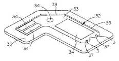
図6は、本発明による発光パネルアセンブリ32の他の形状を示す。発光パネルアセンブリ32は、パネル部材33、1つ以上の光源3、および1つ以上の光放出領域34を有する。さらにパネルアセンブリ32は、パネルアセンブリ32が受容されるキャビティまたは凹部36を有するトレイ35を備える。トレイ35は、パネル33のための端部エッジおよび/または側面エッジ反射板および側面および/または光源3のための裏反射板37とともに裏反射板として機能する。さらに、1つ以上の二次的反射表面または屈折表面38がパネル部材33および/またはトレイ35に設けられ得、長方形でないパネル部材33の1つ以上の角または湾曲部に光の一部を反射させる。これらの二次的な反射表面/屈折表面38は平面か、角度が付けられているか、切り子状かまたは湾曲し得、パネル部材から離れたところで所望のパターンで光の一部を抽出するために使用され得る。図6はまた、1つ以上の光源3から光を照射するパネル部材上の多数の光放出領域34を示している。 FIG. 6 shows another shape of the light emitting
図7は本発明による発光パネルアセンブリ40のさらに他の形状を示す模式図である。発光パネルアセンブリ40は、1つ以上の光放出領域42と、パネルの一方または両端に位置する複数の光源3を有する1つ以上の光遷移領域(混合領域)43とを有する、パネル部材41を備える。各遷移領域は、異なる色および/または強度を有する1つ以上の光源からの光を混合する。本実施態様によると、望ましくは各光源3はそれぞれ、3つの着色LED(赤、青、緑)を各遷移混合領域43に使用することによって、3つのLEDからの光が混合でき、光放出領域42から所望の光放出色が照射されるようにする。あるいは、各光源は、リードフィルム(leadfilm)に接着される多数の着色チップを有する単一のLEDであり得る。また、2色のLEDまたは2つの着色チップを有する単一のLEDが特定の用途に使用され得る。個々のLEDの強度を変化させることによって、実際にはいかなる着色光の放出または白色光の分布も達成され得る。 FIG. 7 is a schematic view showing still another shape of the light emitting
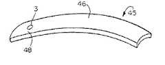
図8は、本発明による発光パネルアセンブリ45のさらに他の形状を示す。発光パネルアセンブリ45は、発光パネル部材46と、該パネル部材46の一端と一体となった光遷移領域48にある光源3とを備える。本実施態様においては、パネル部材46は3次元的に湾曲しているため、例えば美的なデザインの点灯表示が容易に得られるように光線を照射し得る。 FIG. 8 shows still another shape of the light emitting
図9は、本発明による発光パネルアセンブリ50のさらに他の形状を示す。発光パネルアセンブリ50は、多数の光放出領域52を有するパネル部材51、および取り付け支柱および/または取り付けタブ53を備える。本実施態様におけるパネルアセンブリ50は、モジュール式構成要素または他の部品をパネル部材に挿入することを可能とする穴またはキャビティ54および55をパネル部材51に備えることによって、他の部品または構成要素を支持するための構造的部材として機能する。さらにパネル51は、対応する形状の光遷移領域57を受容する独立したキャビティまたは凹部56を備えることができる。該光遷移領域57は、そこに埋め込まれるか、接着されるか、注型されるか、インサート成形されるか、エポキシ樹脂で接着されるか、または他の方法で取り付けられるか配置される1つ以上の光源3と、光の一部を所定の方法で向け直すための遷移領域57上の湾曲した反射表面または屈折表面58および/またはキャビティまたは凹部56の壁とを有する。このように、光遷移領域57および/またはパネル部材は独立した挿入形状であり得、光源がモジュラー式で容易に設置される。反射板58は、キャビティまたは凹部56または挿入物57の反射表面または屈折表面に設置され得る。キャビティまたは凹部56の反射表面または屈折表面に反射板58が設置される場合、キャビティまたは凹部56は、遷移領域57を形成する透明材料を、1つ以上の光源3の周りに注型する金型として機能し得る。 FIG. 9 shows still another shape of the light emitting panel assembly 50 according to the present invention. The light emitting panel assembly 50 includes a panel member 51 having a number of
図10および図11は、本発明による発光パネルアセンブリ60のさらに他の形状を模式的に示す。発光パネルアセンブリ60は、1つ以上の光放出領域62を有するパネル部材61を有する。本実施態様においては、軸外れ光遷移領域63が備えられている。軸外れ光遷移領域63の断面の厚さはパネル部材61の厚さよりも厚く、パネル部材61よりも厚い光遷移領域に埋め込まれるかさもなければ取り付けられた1つ以上の光源3の使用を可能とする。また、3次元反射表面64(図11)が遷移領域63に備えられ得る。さらに、プリズム65(図11)またはテーパー状にされるか、丸められるか、または他の形状とされる端部66(図11a)が光源3に対向するパネルの端部に取り付けられ得て端部反射板として機能する。光源3は互いに対してさまざまな角度に向けられて補償しあい、図10に示されるように遷移領域63において光線67が容易によりよく混合されおよび/またはより長さの短い遷移領域63が使用できるようにする。 10 and 11 schematically show still another shape of the light emitting
図12および図13は、本発明による発光パネルアセンブリ70のさらに他の形状を模式的に示す。発光パネルアセンブリ70は、パネル部材72の一方または両方の端部に位置しそれぞれ単一の光源73を有する1つ以上の光遷移領域71を備える。図12および図13に示される遷移領域71は多数または3次元的表面を利用して光を収集し、および/または1つより多い面に光を収集する。例えば、図12および図13に示される各光遷移領域71は楕円および放物線状の表面74および75を異なる面に有しており、所望の角度で光線76をパネル部材72に向かわせる。 12 and 13 schematically show still another shape of the light emitting
1つ以上の光源を収容するよう所望の寸法にされるパネル部材の一方または両方の端部に1つ以上の光遷移領域を提供し、該光遷移領域に反射表面および/または屈折表面を提供して比較的低い角度で光線をパネル部材に再び向かわせることによって、発光パネル部材を他の方法によって可能なよりもより長く薄くすることができる。例えば、本発明のパネル部材は非常に薄く、例えば厚さ0.125インチ以下である。 Providing one or more light transition regions at one or both ends of a panel member that is sized to receive one or more light sources and providing the light transition region with a reflective and / or refractive surface Thus, by redirecting the light beam to the panel member at a relatively low angle, the light emitting panel member can be made thinner and longer than possible by other methods. For example, the panel member of the present invention is very thin, for example, 0.125 inches or less in thickness.
図14は、本発明による発光パネル部材80のさらに他の形状を模式的に示す。発光パネルアセンブリ80は、発光パネル81と、光遷移領域82に配置されるか、埋め込まれるか、はめ込まれるか(potted)、接着されるか、または他の方法によって取り付けられる1つ以上の光源3とを有する。光遷移領域82は、より効率よく空間を利用できるようパネル部材81に対して傾斜している。傾斜したまたは湾曲した反射表面または屈折表面83はパネル部材81と遷移領域82との接合点に設けられており、光源3からの光をパネル部材81の本体に反射/屈折させて、1つ以上の発光領域84から光がパネル部材の長さに沿って照射されるようにする。 FIG. 14 schematically shows still another shape of the light emitting
図15は、本発明による発光パネルアセンブリ90のさらに他の形状を模式的に示す。発光パネルアセンブリ90は、発光パネル部材92の一方または両方の端部に位置する光遷移領域91を有する。光遷移領域91は、LEDまたは他の適切な光源3を滑り込ませて受容するためのスロット93を有する。好ましくは、スロット93は後部エッジ94から光遷移領域91に延びており、光源3が後ろからスロット93にスライドおよび/またははめ合わされ得る。これにより、光遷移領域がより短くおよび/または薄くなる。光源3にはウィング、タブ、または他の表面95が設けられ、遷移領域91の対応した形状を有する凹部または溝96などに係合され、光源を所定の位置に配置し、所望であれば固定する。また、光源3は、パネル部材92の光遷移領域91にあるスロット93内に埋め込まれるか、はめ込まれるか(potted)、接着されるか、または他の方法によって固定され得る。二次光源97からの光はパネル部材92を通って投射され、表示または他の効果を示す。 FIG. 15 schematically shows still another shape of the light emitting
本願において開示されるさまざまな発光パネルアセンブリは多くの異なる用途に使用され得る。その例としては、液晶表示装置のバックライトまたは一般に照明、装飾および表示照明、自動車用照明、歯科用照明、光線療法または他の医療用照明、膜スイッチ照明(membraineswitch lighting)、およびスポーツ用品およびアパレル用照明などがある。また、パネルアセンブリは、パネル部材および変形部が裏反射板を使用せず透明となるように形成され得る。これにより、パネルアセンブリは例えば、表示が透明パネル部材を通して見えるように、液晶表示装置または他の表示の前部ライトとして使用される。 The various light emitting panel assemblies disclosed herein can be used for many different applications. Examples include liquid crystal display backlights or generally lighting, decoration and display lighting, automotive lighting, dental lighting, phototherapy or other medical lighting, membraineswitch lighting, and sports equipment and apparel There are lighting etc. In addition, the panel assembly may be formed such that the panel member and the deformed portion are transparent without using the back reflector. Thus, the panel assembly is used, for example, as a front light for a liquid crystal display or other display so that the display is visible through the transparent panel member.
本発明はある好適な実施態様に関して示され説明されてきたが、本明細を読み理解した上で、当業者であれば等価的な変更および改変に想到するであろう。本発明はそのような等価的な変更および改変をすべて包含するものであり、クレームの範囲によってのみ制限されるものである。 While the invention has been shown and described with respect to certain preferred embodiments, those skilled in the art will envision equivalent changes and modifications upon reading and understanding this specification. The present invention includes all such equivalent changes and modifications and is limited only by the scope of the claims.
1 発光パネルアセンブリ
2 透明発光パネル
3 光源
4 光遷移領域
10 反射性材料
13 光入力表面
16 開口部DESCRIPTION OF SYMBOLS 1 Light emitting panel assembly 2 Transparent
Claims (5)
Translated fromJapanese該光源は該パネル部材の一方の側にあり、光が該光放出領域へ入る前に該光源からの光を混合するため、該パネル部材は、該光源にきわめて近接する遷移領域を有し、該遷移領域は、該光源からの光をパネル部材へ向け直すため、ほぼ楕円形又は放物線状の反射又は屈折表面を有し、
該パネル部材は、少なくとも1つの中実の光伝導層または光伝達層と、少なくとも1つの中空の光伝導層または光伝達層と、を有し、
該トレイはキャビティ又は凹部を形成し、該光源および該パネル部材が該キャビティ又は凹部内に配置され、および少なくとも1つのフィルム、シート、板又は基板が、該キャビティ又は凹部の上に配置され、そこを通って該パネル部材からの光が発せられ、該フィルム、シート、板又は基板の1つの表面が、発せられる光の放出光線角度分布を制御して特定の用途に適合させるための、1つ以上の反射又は屈折表面を有し、
該トレイは、背面反射板、側面反射板およびエッジ反射板のうちの少なくとも1つとして作用し、予め決められたパターンにおいて該フィルム、シート、板または基板を通って該パネル部材から発せられる光の少なくとも一部を反射または屈折させるための、1つまたはそれ以上の第2の平らな、角度を成した、切子面でカットされた、あるいは湾曲した反射または屈折表面を有する、発光パネルアセンブリ。A light emitting panel assembly having a plurality of light emitting diode light sources, a multilayer light emitting panel member that receives light from the light source for emission from a light emitting region of the panel member,and a tray for holding or positioning the panel member Because
The light source is on one side of the panel member and the panel member has a transition region in close proximity to the light source to mix light from the light source before light enters the light emitting region; The transition region has a substantially elliptical or parabolic reflective or refractive surface to redirect light from the light source to the panel member;
The panel member,possess at least one solid photoconductive layer or light transmission layer, the at least one hollow and the photoconductive layer or the light transmission layer,and
The tray forms a cavity or recess, the light source and the panel member are disposed within the cavity or recess, and at least one film, sheet, plate or substrate is disposed over the cavity or recess, wherein A light is emitted from the panel member through which one surface of the film, sheet, plate or substrate controls the emitted light angle distribution of the emitted light to adapt to a particular application. Having a reflective or refractive surface,
The tray acts as at least one of a back reflector, a side reflector, and an edge reflector and transmits light emitted from the panel member through the film, sheet, plate or substrate in a predetermined pattern. A light emitting panel assemblyhaving one or more second flat, angled, faceted or curved reflective or refractive surfaces for reflecting or refracting at least a portion .
該キャビティ又は凹部内の少なくとも1つの遷移部材と、該キャビティ又は凹部に光が入る前に、光源からの光を混合するために、該遷移部材にきわめて近接した複数の発光ダイオード光源と、
中空の発光アセンブリを形成して、該中空の発光アセンブリから発せられる光を制御して特定の用途に適合させるための、該キャビティ又は凹部の上に配置される少なくとも1つのフィルム、シート、板又は基板と、を有する発光アセンブリであって、
少なくとも1つの該遷移部材は、空気充填キャビティ又は凹部の長さより実質的に小さい長さを有し、該キャビティ又は凹部内に予め決められた方法で光源からの光を向け直すための少なくとも1つのほぼ楕円形又は放物線状の反射又は屈折表面を有し、該トレイは、背面反射板、側面反射板およびエッジ反射板のうちの少なくとも1つとして作用し、予め決められたパターンにおいて該フィルム、シート、板または基板を通って該パネル部材から発せられる光の少なくとも一部を反射または屈折させるための、1つまたはそれ以上の第2の平らな、角度を成した、切子面でカットされた、あるいは湾曲した反射または屈折表面を有する、発光アセンブリ。A tray forming a cavity or recess filled with hollow air;
And at least one transition element in the cavity or recess, before the light enters the cavity orrecess, in order to mix the light fromthe light source, a plurality of light emitting diodes light sources vergeUmate close to the transition member ,
At least one film, sheet, plate, or disposed on the cavity or recess for forming a hollow light emitting assembly to control light emitted from the hollow light emitting assembly to suit a particular applicationa light emitting assembly for chromatic and substrate,and
The at least one transition member has a length substantially less than the length of the air-filled cavity or recess, and at least one for redirecting light fromthe light source in a predetermined manner within the cavity or recess.have a substantially elliptical or parabolic reflecting or refractingsurfaces, the tray includes a rear reflector, acts as at least one of the side reflectors and edge reflector, the film in a predetermined pattern, sheet One or more second flat, angled, faceted cuts for reflecting or refracting at least a portion of the light emitted from the panel member through the plate or substrate, Or a light emitting assemblyhaving a curved reflective or refractive surface .
Applications Claiming Priority (1)
| Application Number | Priority Date | Filing Date | Title |
|---|---|---|---|
| US08/495,176US5613751A (en) | 1995-06-27 | 1995-06-27 | Light emitting panel assemblies |
Related Parent Applications (1)
| Application Number | Title | Priority Date | Filing Date |
|---|---|---|---|
| JP2005285479ADivisionJP2006054196A (en) | 1995-06-27 | 2005-09-29 | Luminous panel assembly |
Publications (2)
| Publication Number | Publication Date |
|---|---|
| JP2007329137A JP2007329137A (en) | 2007-12-20 |
| JP4392441B2true JP4392441B2 (en) | 2010-01-06 |
Family
ID=23967579
Family Applications (5)
| Application Number | Title | Priority Date | Filing Date |
|---|---|---|---|
| JP8168037APendingJPH0921916A (en) | 1995-06-27 | 1996-06-27 | Light-emitting panel assembly |
| JP2005285479AWithdrawnJP2006054196A (en) | 1995-06-27 | 2005-09-29 | Luminous panel assembly |
| JP2007227063AExpired - Fee RelatedJP4392441B2 (en) | 1995-06-27 | 2007-08-31 | Luminous panel assembly |
| JP2007227064AWithdrawnJP2007324144A (en) | 1995-06-27 | 2007-08-31 | Light-emitting panel assembly |
| JP2009208733APendingJP2009289760A (en) | 1995-06-27 | 2009-09-09 | Light emitting panel assembly |
Family Applications Before (2)
| Application Number | Title | Priority Date | Filing Date |
|---|---|---|---|
| JP8168037APendingJPH0921916A (en) | 1995-06-27 | 1996-06-27 | Light-emitting panel assembly |
| JP2005285479AWithdrawnJP2006054196A (en) | 1995-06-27 | 2005-09-29 | Luminous panel assembly |
Family Applications After (2)
| Application Number | Title | Priority Date | Filing Date |
|---|---|---|---|
| JP2007227064AWithdrawnJP2007324144A (en) | 1995-06-27 | 2007-08-31 | Light-emitting panel assembly |
| JP2009208733APendingJP2009289760A (en) | 1995-06-27 | 2009-09-09 | Light emitting panel assembly |
Country Status (4)
| Country | Link |
|---|---|
| US (15) | US5613751A (en) |
| EP (1) | EP0751340B1 (en) |
| JP (5) | JPH0921916A (en) |
| DE (1) | DE69608499T2 (en) |
Cited By (1)
| Publication number | Priority date | Publication date | Assignee | Title |
|---|---|---|---|---|
| RU2596941C2 (en)* | 2011-10-31 | 2016-09-10 | Конинклейке Филипс Н.В. | Compact light-emitting device with wavelength conversion |
Families Citing this family (527)
| Publication number | Priority date | Publication date | Assignee | Title |
|---|---|---|---|---|
| US5613751A (en) | 1995-06-27 | 1997-03-25 | Lumitex, Inc. | Light emitting panel assemblies |
| US7108414B2 (en) | 1995-06-27 | 2006-09-19 | Solid State Opto Limited | Light emitting panel assemblies |
| US20040135273A1 (en)* | 1995-06-27 | 2004-07-15 | Parker Jeffery R. | Methods of making a pattern of optical element shapes on a roll for use in making optical elements on or in substrates |
| US6185356B1 (en) | 1995-06-27 | 2001-02-06 | Lumitex, Inc. | Protective cover for a lighting device |
| US6712481B2 (en)* | 1995-06-27 | 2004-03-30 | Solid State Opto Limited | Light emitting panel assemblies |
| JP3368110B2 (en)* | 1995-08-01 | 2003-01-20 | キヤノン株式会社 | Light source device and optical equipment |
| US5947578A (en)* | 1995-10-24 | 1999-09-07 | Nu-Tech & Engineering, Inc. | Back lighting device |
| US5895115A (en)* | 1996-01-16 | 1999-04-20 | Lumitex, Inc. | Light emitting panel assemblies for use in automotive applications and the like |
| US5677972A (en)* | 1996-02-21 | 1997-10-14 | Tir Technologies, Inc. | High efficiency direct coupling of radiant electromagnetic energy into dielectric wave guide structure |
| US6814700B1 (en)* | 1996-03-04 | 2004-11-09 | Heartport, Inc. | Soft tissue retractor and method for providing surgical access |
| US6048309A (en)* | 1996-03-04 | 2000-04-11 | Heartport, Inc. | Soft tissue retractor and delivery device therefor |
| US5810721A (en)* | 1996-03-04 | 1998-09-22 | Heartport, Inc. | Soft tissue retractor and method for providing surgical access |
| JP3466817B2 (en)* | 1996-05-02 | 2003-11-17 | ローム株式会社 | LED light emitting device and manufacturing method |
| JP3860249B2 (en)* | 1996-05-02 | 2006-12-20 | ローム株式会社 | Surface emitting lighting device |
| US6550949B1 (en) | 1996-06-13 | 2003-04-22 | Gentex Corporation | Systems and components for enhancing rear vision from a vehicle |
| US20040239243A1 (en)* | 1996-06-13 | 2004-12-02 | Roberts John K. | Light emitting assembly |
| US5803579A (en)* | 1996-06-13 | 1998-09-08 | Gentex Corporation | Illuminator assembly incorporating light emitting diodes |
| KR0169444B1 (en)* | 1996-07-11 | 1999-01-15 | 김광호 | Display device |
| US6164789A (en)* | 1996-07-12 | 2000-12-26 | Honeywell International Inc. | Illumination sources and systems |
| US6473554B1 (en) | 1996-12-12 | 2002-10-29 | Teledyne Lighting And Display Products, Inc. | Lighting apparatus having low profile |
| DE19700472A1 (en)* | 1997-01-09 | 1998-07-23 | Bosch Gmbh Robert | Lighting unit |
| US5913594A (en)* | 1997-02-25 | 1999-06-22 | Iimura; Keiji | Flat panel light source device and passive display device utilizing the light source device |
| JPH10260405A (en) | 1997-03-18 | 1998-09-29 | Seiko Epson Corp | Lighting device, liquid crystal display device and electronic equipment |
| US6739744B2 (en)* | 1997-07-02 | 2004-05-25 | Lumitex, Inc. | Light delivery systems and applications thereof |
| US7306559B2 (en)* | 1997-07-02 | 2007-12-11 | Lumitex, Inc. | Illuminated surgical retractor |
| US6591049B2 (en) | 1997-07-02 | 2003-07-08 | Lumitex, Inc. | Light delivery systems and applications thereof |
| US6295405B1 (en)* | 1997-07-25 | 2001-09-25 | Physical Optics Corporation | Light pipe for a backlighting system |
| US6042241A (en)* | 1997-07-31 | 2000-03-28 | Litton Systems, Inc. | Backlight with integral illumination source |
| US7038398B1 (en) | 1997-08-26 | 2006-05-02 | Color Kinetics, Incorporated | Kinetic illumination system and methods |
| US6717376B2 (en) | 1997-08-26 | 2004-04-06 | Color Kinetics, Incorporated | Automotive information systems |
| US7064498B2 (en) | 1997-08-26 | 2006-06-20 | Color Kinetics Incorporated | Light-emitting diode based products |
| US20030133292A1 (en) | 1999-11-18 | 2003-07-17 | Mueller George G. | Methods and apparatus for generating and modulating white light illumination conditions |
| US6897624B2 (en) | 1997-08-26 | 2005-05-24 | Color Kinetics, Incorporated | Packaged information systems |
| US7186003B2 (en) | 1997-08-26 | 2007-03-06 | Color Kinetics Incorporated | Light-emitting diode based products |
| US7385359B2 (en) | 1997-08-26 | 2008-06-10 | Philips Solid-State Lighting Solutions, Inc. | Information systems |
| DE19740317C1 (en)* | 1997-09-13 | 1999-02-18 | Bosch Gmbh Robert | Motor vehicle lamp with light conductor system |
| JPH11126029A (en)* | 1997-10-22 | 1999-05-11 | Yazaki Corp | display |
| US6238074B1 (en)* | 1997-12-09 | 2001-05-29 | Cooper Automotive Products, Inc. | Optical waveguide structures |
| US6168302B1 (en) | 1997-12-09 | 2001-01-02 | Cooper Automotive Products, Inc. | Hybrid distributed lighting system for a vehicle |
| US6164805A (en)* | 1998-04-20 | 2000-12-26 | Federal-Mogul World Wide, Inc. | Illuminated door handle for a vehicle |
| US6193399B1 (en) | 1997-12-09 | 2001-02-27 | Cooper Automotive Products, Inc. | Optical waveguide structures for vehicle lighting |
| US7598686B2 (en) | 1997-12-17 | 2009-10-06 | Philips Solid-State Lighting Solutions, Inc. | Organic light emitting diode methods and apparatus |
| EP1044116A2 (en)* | 1997-12-31 | 2000-10-18 | Gentex Corporation | Vehicle vision system |
| US6200134B1 (en) | 1998-01-20 | 2001-03-13 | Kerr Corporation | Apparatus and method for curing materials with radiation |
| JPH11284803A (en)* | 1998-03-27 | 1999-10-15 | Citizen Electronics Co Ltd | Linear light source unit |
| US6134092A (en)* | 1998-04-08 | 2000-10-17 | Teledyne Lighting And Display Products, Inc. | Illumination device for non-emissive displays |
| JP4159059B2 (en)* | 1998-06-05 | 2008-10-01 | シチズン電子株式会社 | Planar light source unit |
| US6139176A (en)* | 1998-07-02 | 2000-10-31 | Federal-Mogul World Wide, Inc. | Optical waveguide structure with raised or embedded waveguides |
| ES2205644T3 (en)* | 1998-07-08 | 2004-05-01 | Liebherr-Hausgerate Ochsenhausen Gmbh | INTERIOR LIGHTING FOR REFRIGERATOR. |
| EP0974785A1 (en)* | 1998-07-21 | 2000-01-26 | Combined Optical Industries Limited | Illuminator |
| DE19835922A1 (en)* | 1998-08-07 | 2000-02-10 | Siteco Beleuchtungstech Gmbh | Optical display device |
| AU5024699A (en)* | 1998-08-14 | 2000-03-06 | Eclair, Spol S R.O.. | Light optical system, especially for information, advertising illumination or decorative purposes |
| US6430339B1 (en) | 1998-10-15 | 2002-08-06 | Federal-Mogul World Wide, Inc. | Low profile waveguide system |
| FI105588B (en) | 1998-12-10 | 2000-09-15 | Nokia Mobile Phones Ltd | Improved light source arrangement for flat applications |
| US6129444A (en)* | 1998-12-10 | 2000-10-10 | L-3 Communications Corporation | Display backlight with white balance compensation |
| US6256445B1 (en)* | 1998-12-11 | 2001-07-03 | Lucent Technologies Inc. | Illuminated optical connection port for use in a fiber distribution shelf assembly of a fiber administration system having integral line tracing capabilities |
| JP3283842B2 (en)* | 1999-01-08 | 2002-05-20 | 日本電気株式会社 | Backlight device for liquid crystal display |
| US6325524B1 (en)* | 1999-01-29 | 2001-12-04 | Agilent Technologies, Inc. | Solid state based illumination source for a projection display |
| JP2000235183A (en)* | 1999-02-16 | 2000-08-29 | Matsushita Electric Ind Co Ltd | Illumination device and portable information device having the same |
| US6402334B1 (en) | 1999-02-18 | 2002-06-11 | Garmin Corporation | Light pipe with quadraspherical depressions for display panels |
| US6752505B2 (en)* | 1999-02-23 | 2004-06-22 | Solid State Opto Limited | Light redirecting films and film systems |
| US20050024849A1 (en)* | 1999-02-23 | 2005-02-03 | Parker Jeffery R. | Methods of cutting or forming cavities in a substrate for use in making optical films, components or wave guides |
| US6827456B2 (en)* | 1999-02-23 | 2004-12-07 | Solid State Opto Limited | Transreflectors, transreflector systems and displays and methods of making transreflectors |
| US7364341B2 (en)* | 1999-02-23 | 2008-04-29 | Solid State Opto Limited | Light redirecting films including non-interlockable optical elements |
| US7088333B1 (en) | 1999-03-12 | 2006-08-08 | Matsushita Electric Industrial Co., Ltd. | Surface lighting device and portable terminal using the same |
| JP2000267093A (en)* | 1999-03-19 | 2000-09-29 | Matsushita Electric Ind Co Ltd | Illumination device and portable information device having the same |
| CH690247A5 (en)* | 1999-03-24 | 2000-06-15 | Gerhard Staufert | Light body structure has light conducting body with light conducting zone, light source close to center of structure, central light entry zone, peripheral output zone |
| US6200002B1 (en)* | 1999-03-26 | 2001-03-13 | Philips Electronics North America Corp. | Luminaire having a reflector for mixing light from a multi-color array of leds |
| US6206534B1 (en)* | 1999-04-09 | 2001-03-27 | Cmos Sensor, Inc. | Illumination device for use in image reading applications |
| US6257737B1 (en)* | 1999-05-20 | 2001-07-10 | Philips Electronics Na | Low-profile luminaire having a reflector for mixing light from a multi-color linear array of LEDs |
| DE19931299C2 (en)* | 1999-07-07 | 2001-08-30 | Philips Corp Intellectual Pty | Backlit screen |
| GB9918821D0 (en)* | 1999-08-11 | 1999-10-13 | Signwaves Limited | Edgelit display panel assembly |
| US6290713B1 (en)* | 1999-08-24 | 2001-09-18 | Thomas A. Russell | Flexible illuminators for phototherapy |
| US6676279B1 (en)* | 1999-10-04 | 2004-01-13 | David A. Hubbell | Area lighting device using discrete light sources, such as LEDs |
| KR100421688B1 (en) | 1999-11-11 | 2004-03-10 | 도요다 고세이 가부시키가이샤 | Full-color Light Source Unit |
| EP1106913B1 (en) | 1999-12-08 | 2005-05-25 | MENTOR GMBH & CO. | Circuit boards surface mountable display element |
| DE29921689U1 (en)* | 1999-12-09 | 2001-04-19 | Emde Thomas | Light-emitting wall, wall opening, ceiling and facade cladding system for buildings |
| JP2001166150A (en)* | 1999-12-13 | 2001-06-22 | Nitto Denko Corp | Light guide plate, surface light source device and liquid crystal display device |
| US6666567B1 (en)* | 1999-12-28 | 2003-12-23 | Honeywell International Inc. | Methods and apparatus for a light source with a raised LED structure |
| JP4862208B2 (en)* | 1999-12-27 | 2012-01-25 | パナソニック株式会社 | LCD backlight structure |
| DE60033264T2 (en)* | 1999-12-28 | 2007-11-08 | Fujitsu Kasei Ltd., Yokohama | Lighting apparatus for display |
| DE10001412C2 (en)* | 2000-01-14 | 2001-12-06 | Siemens Ag | Lighting unit |
| JP2001202817A (en)* | 2000-01-19 | 2001-07-27 | Advanced Display Inc | Flat panel display |
| US6347874B1 (en) | 2000-02-16 | 2002-02-19 | 3M Innovative Properties Company | Wedge light extractor with risers |
| US6893135B2 (en)* | 2000-03-16 | 2005-05-17 | 3M Innovative Properties Company | Light guides suitable for illuminated displays |
| US20010033480A1 (en)* | 2000-04-12 | 2001-10-25 | Nikon Corporation | LCD illuminating device |
| PT1422975E (en)* | 2000-04-24 | 2010-07-09 | Philips Solid State Lighting | Light-emitting diode based product |
| US7642730B2 (en) | 2000-04-24 | 2010-01-05 | Philips Solid-State Lighting Solutions, Inc. | Methods and apparatus for conveying information via color of light |
| TWI240788B (en)* | 2000-05-04 | 2005-10-01 | Koninkl Philips Electronics Nv | Illumination system, light mixing chamber and display device |
| US6767106B2 (en)* | 2000-05-08 | 2004-07-27 | Lexalite International Corporation | Edge-lit luminaire having prismatic optical control |
| FI111303B (en) | 2000-05-16 | 2003-06-30 | Polar Electro Oy | Connecting a light source to a background plate |
| JP3642263B2 (en)* | 2000-05-23 | 2005-04-27 | セイコーエプソン株式会社 | Liquid crystal device and electronic device |
| TW442675B (en) | 2000-07-06 | 2001-06-23 | Acer Comm & Amp Multimedia Inc | Back light plate module |
| EP1174661A1 (en)* | 2000-07-17 | 2002-01-23 | Designedge Europe Limited | A luminaire |
| WO2002006891A1 (en)* | 2000-07-17 | 2002-01-24 | Siemens Aktiengesellschaft | Display |
| US6568832B1 (en)* | 2000-08-04 | 2003-05-27 | Maxtor Corporation | Color mixing device |
| US6443582B1 (en) | 2000-08-30 | 2002-09-03 | Visteon Corporation | Edge-lit light assembly with light guiding structures |
| DE10043516A1 (en)* | 2000-09-01 | 2002-03-28 | Thomas Emde | furniture |
| DE10055799A1 (en)* | 2000-11-10 | 2002-05-29 | Osram Opto Semiconductors Gmbh | Method for producing a light coupling surface of a light guide |
| JP2002163914A (en)* | 2000-11-24 | 2002-06-07 | Nec Corp | Lighting equipment, liquid crystal display using this lighting equipment and its manufacturing method |
| KR100788382B1 (en)* | 2000-12-13 | 2007-12-31 | 엘지.필립스 엘시디 주식회사 | Backlight Unit of LCD |
| TW594277B (en)* | 2000-12-19 | 2004-06-21 | Taiwan Nano Electro Opt Tech | Face light source device |
| US6547416B2 (en) | 2000-12-21 | 2003-04-15 | Koninklijke Philips Electronics N.V. | Faceted multi-chip package to provide a beam of uniform white light from multiple monochrome LEDs |
| US7004613B2 (en)* | 2000-12-28 | 2006-02-28 | Au Optronics Corp. | Display structure |
| DE10065728B4 (en)* | 2000-12-29 | 2009-04-23 | Robert Bosch Gmbh | Backlight device and liquid crystal display and their use in a motor vehicle |
| DE10102586A1 (en)* | 2001-01-20 | 2002-07-25 | Philips Corp Intellectual Pty | Luminair with light emission surface and punctiform light sources |
| DE10102585A1 (en)* | 2001-01-20 | 2002-07-25 | Philips Corp Intellectual Pty | Mixed colour luminair with differently coloured light sources and light emission surface |
| US6592238B2 (en) | 2001-01-31 | 2003-07-15 | Light Technologies, Inc. | Illumination device for simulation of neon lighting |
| US6557282B1 (en) | 2001-02-02 | 2003-05-06 | Ilight Technologies, Inc. | Portable illuminated outdoor advertising display |
| AUPR401101A0 (en)* | 2001-03-27 | 2001-04-26 | Solaglo Pty Ltd | Illuminated background display apparatus |
| US7703970B2 (en) | 2001-03-27 | 2010-04-27 | Sotek Australia Pty Ltd | Illuminated background display apparatus |
| US6592234B2 (en) | 2001-04-06 | 2003-07-15 | 3M Innovative Properties Company | Frontlit display |
| US6738051B2 (en) | 2001-04-06 | 2004-05-18 | 3M Innovative Properties Company | Frontlit illuminated touch panel |
| US6568822B2 (en) | 2001-04-06 | 2003-05-27 | 3M Innovative Properties Company | Linear illumination source |
| US6791636B2 (en)* | 2001-05-10 | 2004-09-14 | Lumilecs Lighting U.S., Llc | Backlight for a color LCD |
| US7001058B2 (en)* | 2001-05-16 | 2006-02-21 | Ben-Zion Inditsky | Ultra-thin backlight |
| US8684584B2 (en)* | 2001-05-16 | 2014-04-01 | Benzion Inditsky | Ultra-thin backlight |
| US7336980B1 (en) | 2001-05-29 | 2008-02-26 | Nokia Corporation | Outer decorative cover for attachment to a wireless communication device including a printed circuit board and an associated light source mounted in an interior of the wireless device |
| JP4049267B2 (en)* | 2001-06-01 | 2008-02-20 | フィリップス ルミレッズ ライティング カンパニー リミテッド ライアビリティ カンパニー | Compact lighting system and display device |
| KR100965201B1 (en)* | 2001-06-12 | 2010-06-24 | 웰스테트 테라퓨틱스 코포레이션 | Compounds for the treatment of metabolic diseases |
| JP2002372605A (en)* | 2001-06-15 | 2002-12-26 | Fuji Photo Film Co Ltd | Optical element and display body using the same |
| US6576887B2 (en) | 2001-08-15 | 2003-06-10 | 3M Innovative Properties Company | Light guide for use with backlit display |
| WO2003019074A1 (en)* | 2001-08-27 | 2003-03-06 | Koninklijke Philips Electronics N.V. | Light panel with enlarged viewing window |
| US6790396B2 (en) | 2001-08-29 | 2004-09-14 | Nokia Corporation | Method of making illuminated covers |
| NL1019121C2 (en)* | 2001-10-05 | 2003-04-08 | Datascan Group B V | Flat, homogeneous light source. |
| JP2003173712A (en)* | 2001-12-05 | 2003-06-20 | Toyoda Gosei Co Ltd | Light emitting device and display |
| KR20050044695A (en)* | 2001-12-05 | 2005-05-12 | 솔리드 스테이트 옵토 리미티드 | Transreflectors, transreflector systems and displays and methods of making transreflectors |
| KR20040071707A (en)* | 2001-12-07 | 2004-08-12 | 루미리즈 라이팅 유에스 엘엘씨 | Compact lighting system and display device |
| US6655825B2 (en)* | 2001-12-28 | 2003-12-02 | Koninklijke Philips Electronics N.V. | White light source for LCD backlight |
| US20030215766A1 (en)* | 2002-01-11 | 2003-11-20 | Ultradent Products, Inc. | Light emitting systems and kits that include a light emitting device and one or more removable lenses |
| DE10201556A1 (en) | 2002-01-17 | 2003-07-31 | Ludwig Leuchten Kg | plate lamp |
| JP3770558B2 (en)* | 2002-01-18 | 2006-04-26 | シチズン電子株式会社 | Light guide plate |
| US20030189290A1 (en)* | 2002-01-22 | 2003-10-09 | Moody Ernest W. | Video poker games |
| JP3980890B2 (en)* | 2002-01-23 | 2007-09-26 | シャープ株式会社 | Light guide plate and light source device and display device including the same |
| US6908204B2 (en)* | 2002-02-02 | 2005-06-21 | Edward Robert Kraft | Flat panel luminaire having embedded light guides |
| US6816083B2 (en) | 2002-02-04 | 2004-11-09 | Nokia Corporation | Electronic device with cover including a radio frequency indentification module |
| EP1478954B1 (en)* | 2002-02-22 | 2007-12-05 | Lumileds Lighting B.V. | Compact lighting system and display device |
| US20030179564A1 (en)* | 2002-03-13 | 2003-09-25 | Ganci Joseph D. | Edge illuminated visual display apparatus |
| US6874924B1 (en) | 2002-03-14 | 2005-04-05 | Ilight Technologies, Inc. | Illumination device for simulation of neon lighting |
| US6666563B2 (en) | 2002-04-12 | 2003-12-23 | Dahvid N. Brown | Illumination device |
| US7859759B2 (en)* | 2002-05-20 | 2010-12-28 | Sabic Innovative Plastics Ip B.V. | Film, backlight displays, and methods for making the same |
| US6862141B2 (en)* | 2002-05-20 | 2005-03-01 | General Electric Company | Optical substrate and method of making |
| US7180672B2 (en)* | 2002-05-20 | 2007-02-20 | General Electric Company | Optical substrate and method of making |
| FR2840388B1 (en)* | 2002-05-31 | 2004-07-30 | Valeo Vision | SIGNAL LIGHT COMPRISING AN OPTICAL PART PROVIDING A SELF-CONTAINED SIGNALING FUNCTION |
| JP3923867B2 (en)* | 2002-07-26 | 2007-06-06 | 株式会社アドバンスト・ディスプレイ | Planar light source device and liquid crystal display device using the same |
| JP2004095390A (en)* | 2002-08-30 | 2004-03-25 | Fujitsu Display Technologies Corp | Lighting device and display device |
| US20040061810A1 (en)* | 2002-09-27 | 2004-04-01 | Lumileds Lighting, U.S., Llc | Backlight for a color LCD using wavelength-converted light emitting devices |
| US6836611B2 (en)* | 2002-10-03 | 2004-12-28 | J. W. Speaker Corporation | Light guide and lateral illuminator |
| US7406245B2 (en) | 2004-07-27 | 2008-07-29 | Lumitex, Inc. | Flat optical fiber light emitters |
| US20070248307A1 (en)* | 2002-10-04 | 2007-10-25 | Page David J | Transparent light emitting members and method of manufacture |
| US6910783B2 (en)* | 2002-10-04 | 2005-06-28 | Lumitex, Inc. | Transparent light emitting members and method of manufacture |
| US7310071B2 (en) | 2002-10-18 | 2007-12-18 | Kopin Corporation | Instrument panel with active display |
| US20040108970A1 (en)* | 2002-12-04 | 2004-06-10 | Nealon Brian Clark | Vehical graphical message display system |
| US6866678B2 (en) | 2002-12-10 | 2005-03-15 | Interbational Technology Center | Phototherapeutic treatment methods and apparatus |
| TW585275U (en)* | 2002-12-17 | 2004-04-21 | Hon Hai Prec Ind Co Ltd | Light source system |
| US6952627B2 (en)* | 2002-12-18 | 2005-10-04 | General Electric Company | Method and apparatus for fabricating light management substrates |
| US6893394B2 (en)* | 2002-12-19 | 2005-05-17 | Ethicon, Inc. | Illuminated and vacuum assisted retractor |
| US20040120019A1 (en)* | 2002-12-24 | 2004-06-24 | Chin-Hsing Chou | Object short-range projection light conduction structure |
| RU2240471C2 (en)* | 2002-12-24 | 2004-11-20 | Марков Валерий Николаевич | Fiber-optic chandelier built around light-emitting diodes |
| WO2004070262A2 (en)* | 2003-02-04 | 2004-08-19 | Ilight Technologies, Inc. | Flexible illumination device for simulating neon lighting |
| US7417782B2 (en)* | 2005-02-23 | 2008-08-26 | Pixtronix, Incorporated | Methods and apparatus for spatial light modulation |
| US7008097B1 (en) | 2003-02-25 | 2006-03-07 | Ilight Technologies, Inc. | Illumination device for simulating neon or fluorescent lighting including a waveguide and a scattering cap |
| US7004602B2 (en)* | 2003-02-25 | 2006-02-28 | Ryan Waters | LED light apparatus and methodology |
| US6969180B2 (en) | 2003-02-25 | 2005-11-29 | Ryan Waters | LED light apparatus and methodology |
| US7134777B2 (en)* | 2003-03-21 | 2006-11-14 | Hon Hai Precision Ind. Co., Ltd. | Surface lighting device with closed oblique reflector |
| DE10314352A1 (en)* | 2003-03-31 | 2004-10-14 | Hella Kg Hueck & Co. | Illumination device for vehicle interior has light guide part of light conducting element with input coupling surfaces and holders at both ends for mirrors that leave input coupling surfaces exposed |
| AU2003902073A0 (en)* | 2003-05-01 | 2003-05-15 | Kevin Raymond Deguara | A lighting substrate |
| US20070006493A1 (en)* | 2003-05-12 | 2007-01-11 | Arnold Eberwein | Illuminated license plate for vehicles and vehicle provided with the same |
| TWI321248B (en)* | 2003-05-12 | 2010-03-01 | Au Optronics Corp | Led backlight module |
| US7118251B1 (en) | 2003-05-23 | 2006-10-10 | Ilight Technologies, Inc. | Illumination device for simulating channel letters |
| US6945683B2 (en)* | 2003-05-30 | 2005-09-20 | Guide Corporation | Thin lamp assembly method |
| US7044627B2 (en)* | 2003-05-30 | 2006-05-16 | Mertz John C | Display retainer and backlight |
| GB0313044D0 (en)* | 2003-06-06 | 2003-07-09 | Cambridge Flat Projection | Flat panel scanning illuminator |
| US6932492B2 (en)* | 2003-06-13 | 2005-08-23 | Aaa Doodads, L.L.C. | Combination lamp assembly |
| US20040264899A1 (en)* | 2003-06-13 | 2004-12-30 | Peterson James F. | Flat plastic optical fiber and illumination apparatus using such fiber |
| US7163305B2 (en) | 2003-06-25 | 2007-01-16 | Gemtron Corporation | Illuminated shelf |
| US7510316B2 (en)* | 2003-07-14 | 2009-03-31 | Koninklijke Philips Electronics N.V. | Ultra compact illumination system for display systems |
| CN100401534C (en)* | 2003-08-27 | 2008-07-09 | 宇东科技股份有限公司 | Light emitting diode element light emitting device, backlight module and light source adjusting method thereof |
| US20070031641A1 (en)* | 2003-09-05 | 2007-02-08 | 3M Innovative Properties Company | License plate for back illumination and method for making same |
| KR100567249B1 (en)* | 2003-09-06 | 2006-04-03 | 현대모비스 주식회사 | Light guide plate for liquid crystal display backlight and liquid crystal display module of vehicle audio using this light guide plate |
| JP2007505337A (en)* | 2003-09-08 | 2007-03-08 | コニンクリユケ フィリップス エレクトロニクス エヌ.ブイ. | Light guide system having a plurality of light transmitting rods |
| KR101084838B1 (en)* | 2003-09-08 | 2011-11-21 | 치메이 이노럭스 코포레이션 | Body and electronic devices |
| SG116508A1 (en)* | 2003-10-23 | 2005-11-28 | San Ho Entpr Co Ltd | A light-inverse type guidelight plate. |
| TW200519811A (en)* | 2003-12-02 | 2005-06-16 | Display Optronics Corp M | Surface light source device |
| AU2003304596A1 (en)* | 2003-12-05 | 2005-06-24 | Nokia Corporation | A display and a method of providing a display |
| US7182492B1 (en)* | 2003-12-22 | 2007-02-27 | Robert Louis Walter | License plate system having enhanced illumination |
| US7072092B2 (en)* | 2003-12-31 | 2006-07-04 | General Electric Company | Optical substrate with modulated structure |
| KR100590535B1 (en)* | 2004-01-24 | 2006-06-15 | 삼성전자주식회사 | Backlight unit |
| JP4338540B2 (en)* | 2004-02-05 | 2009-10-07 | 三菱電機株式会社 | Planar light source device and display device using the same |
| TWI271583B (en)* | 2004-03-09 | 2007-01-21 | Au Optronics Corp | Light guide of backlight unit |
| ATE375896T1 (en)* | 2004-04-07 | 2007-11-15 | 3M Innovative Properties Co | LICENSE PLATE ARRANGEMENT WITH LIGHT SOURCE AND BACKLIT LICENSE PLATE |
| TWI251701B (en)* | 2004-05-13 | 2006-03-21 | Au Optronics Corp | Lighting positioning device |
| TWI314232B (en)* | 2004-05-28 | 2009-09-01 | Epistar Corp | A second light-guided planar light source device |
| JP4229001B2 (en)* | 2004-06-02 | 2009-02-25 | ソニー株式会社 | Illumination device and liquid crystal display device |
| US7570846B2 (en)* | 2004-06-21 | 2009-08-04 | Oree, Advanced Illumination Solutions Inc. | High efficacy waveguide coupler |
| FR2874993B1 (en)* | 2004-09-07 | 2008-07-18 | Valeo Vision Sa | LIGHT GUIDE LIGHTING AND / OR SIGNALING DEVICE |
| US20080043490A1 (en)* | 2005-09-09 | 2008-02-21 | Fusion Optix Inc. | Enhanced Light Guide |
| KR100638614B1 (en)* | 2004-09-14 | 2006-10-26 | 삼성전기주식회사 | Backlight device for liquid crystal display device and liquid crystal display device having same |
| TWM269461U (en)* | 2004-12-03 | 2005-07-01 | Innolux Display Corp | Light guiding device and backlight module using the same |
| CN100529874C (en)* | 2004-12-17 | 2009-08-19 | 鸿富锦精密工业(深圳)有限公司 | Light guide plate |
| US7908080B2 (en) | 2004-12-31 | 2011-03-15 | Google Inc. | Transportation routing |
| JP5140922B2 (en)* | 2005-01-17 | 2013-02-13 | オムロン株式会社 | Light emitting light source and light emitting light source array |
| US7686839B2 (en)* | 2005-01-26 | 2010-03-30 | Lumitex, Inc. | Phototherapy treatment devices for applying area lighting to a wound |
| US7374324B2 (en) | 2005-02-09 | 2008-05-20 | Dura Global Technologies, Inc. | LED molded light guide |
| JP4442766B2 (en)* | 2005-02-18 | 2010-03-31 | 株式会社エンプラス | Light guide plate, surface light source device and display device |
| CN2785066Y (en)* | 2005-02-18 | 2006-05-31 | 群康科技(深圳)有限公司 | Display module |
| US20060189849A1 (en)* | 2005-02-22 | 2006-08-24 | Sharratt Todd W | Surgical illumination device and method of using |
| US20060209012A1 (en)* | 2005-02-23 | 2006-09-21 | Pixtronix, Incorporated | Devices having MEMS displays |
| US8310442B2 (en) | 2005-02-23 | 2012-11-13 | Pixtronix, Inc. | Circuits for controlling display apparatus |
| US7271945B2 (en) | 2005-02-23 | 2007-09-18 | Pixtronix, Inc. | Methods and apparatus for actuating displays |
| US7755582B2 (en)* | 2005-02-23 | 2010-07-13 | Pixtronix, Incorporated | Display methods and apparatus |
| US7742016B2 (en)* | 2005-02-23 | 2010-06-22 | Pixtronix, Incorporated | Display methods and apparatus |
| US9261694B2 (en) | 2005-02-23 | 2016-02-16 | Pixtronix, Inc. | Display apparatus and methods for manufacture thereof |
| US8519945B2 (en) | 2006-01-06 | 2013-08-27 | Pixtronix, Inc. | Circuits for controlling display apparatus |
| US9158106B2 (en) | 2005-02-23 | 2015-10-13 | Pixtronix, Inc. | Display methods and apparatus |
| US8159428B2 (en) | 2005-02-23 | 2012-04-17 | Pixtronix, Inc. | Display methods and apparatus |
| US9087486B2 (en) | 2005-02-23 | 2015-07-21 | Pixtronix, Inc. | Circuits for controlling display apparatus |
| US7999994B2 (en) | 2005-02-23 | 2011-08-16 | Pixtronix, Inc. | Display apparatus and methods for manufacture thereof |
| US7304786B2 (en)* | 2005-02-23 | 2007-12-04 | Pixtronix, Inc. | Methods and apparatus for bi-stable actuation of displays |
| US9082353B2 (en) | 2010-01-05 | 2015-07-14 | Pixtronix, Inc. | Circuits for controlling display apparatus |
| US7405852B2 (en)* | 2005-02-23 | 2008-07-29 | Pixtronix, Inc. | Display apparatus and methods for manufacture thereof |
| US9229222B2 (en) | 2005-02-23 | 2016-01-05 | Pixtronix, Inc. | Alignment methods in fluid-filled MEMS displays |
| US7746529B2 (en) | 2005-02-23 | 2010-06-29 | Pixtronix, Inc. | MEMS display apparatus |
| US7675665B2 (en) | 2005-02-23 | 2010-03-09 | Pixtronix, Incorporated | Methods and apparatus for actuating displays |
| US8482496B2 (en) | 2006-01-06 | 2013-07-09 | Pixtronix, Inc. | Circuits for controlling MEMS display apparatus on a transparent substrate |
| US20070205969A1 (en) | 2005-02-23 | 2007-09-06 | Pixtronix, Incorporated | Direct-view MEMS display devices and methods for generating images thereon |
| US7616368B2 (en) | 2005-02-23 | 2009-11-10 | Pixtronix, Inc. | Light concentrating reflective display methods and apparatus |
| US7502159B2 (en) | 2005-02-23 | 2009-03-10 | Pixtronix, Inc. | Methods and apparatus for actuating displays |
| US7304785B2 (en) | 2005-02-23 | 2007-12-04 | Pixtronix, Inc. | Display methods and apparatus |
| TWI288851B (en)* | 2005-03-09 | 2007-10-21 | Hannstar Display Corp | Backlight source module |
| US20060217787A1 (en)* | 2005-03-23 | 2006-09-28 | Eastman Kodak Company | Light therapy device |
| JP4721160B2 (en)* | 2005-03-29 | 2011-07-13 | ミネベア株式会社 | Surface lighting device |
| JP4404799B2 (en)* | 2005-04-04 | 2010-01-27 | Nec液晶テクノロジー株式会社 | LIGHTING DEVICE AND LIQUID CRYSTAL DISPLAY DEVICE PROVIDED WITH THE LIGHTING DEVICE |
| CA2620144A1 (en)* | 2005-04-06 | 2006-10-12 | Tir Technology Lp | Lighting module with compact colour mixing and collimating optics |
| TWM276216U (en)* | 2005-04-22 | 2005-09-21 | Innolux Display Corp | Back light module |
| TWM279352U (en)* | 2005-05-06 | 2005-11-01 | Lighthouse Technology Co Ltd | Photo power supply device capable of being controlled by programs |
| KR100629053B1 (en) | 2005-05-19 | 2006-09-26 | 삼성전자주식회사 | Key pad assembly |
| DE102005042523A1 (en)* | 2005-05-31 | 2006-12-07 | Osram Opto Semiconductors Gmbh | lighting device |
| JP2008203281A (en)* | 2005-06-03 | 2008-09-04 | Sharp Corp | Linear light source backlight system and flat display device |
| WO2006131924A2 (en) | 2005-06-07 | 2006-12-14 | Oree, Advanced Illumination Solutions Inc. | Illumination apparatus |
| US8272758B2 (en) | 2005-06-07 | 2012-09-25 | Oree, Inc. | Illumination apparatus and methods of forming the same |
| US8215815B2 (en) | 2005-06-07 | 2012-07-10 | Oree, Inc. | Illumination apparatus and methods of forming the same |
| DE102005027530B4 (en)* | 2005-06-15 | 2008-11-06 | Dr. Schneider Kunststoffwerke Gmbh | Illumination module for backlighting and illumination of hollow setting wheels, markings or function display |
| JP2007005309A (en)* | 2005-06-23 | 2007-01-11 | Samsung Electronics Co Ltd | Light guide plate, backlight assembly, and liquid crystal display device having the same |
| KR100638874B1 (en)* | 2005-07-06 | 2006-10-27 | 삼성전기주식회사 | A light source-light guide plate structure of a backlight device having an LED light source inserted into the light guide plate and a backlight device including the same |
| JP2007027099A (en)* | 2005-07-13 | 2007-02-01 | Samsung Electronics Co Ltd | Backlight assembly, display substrate, display device having the same, display substrate, and manufacturing method thereof |
| JP4728067B2 (en)* | 2005-08-19 | 2011-07-20 | シチズン電子株式会社 | Seat switch module |
| TW200709243A (en)* | 2005-08-19 | 2007-03-01 | Citizen Electronics | Sheet switch, sheet switch module and panel switch |
| USD535707S1 (en) | 2005-08-25 | 2007-01-23 | Mattel, Inc. | Electronic toy house |
| CN100454101C (en)* | 2005-09-21 | 2009-01-21 | 鸿富锦精密工业(深圳)有限公司 | light guide plate |
| USD545983S1 (en) | 2005-09-23 | 2007-07-03 | Lightwedge, Llc | Compact device for illuminating a flat surface |
| USD533773S1 (en) | 2005-09-26 | 2006-12-19 | Mattel, Inc. | Packaging for a toy |
| DE102005052356A1 (en)* | 2005-09-30 | 2007-04-12 | Osram Opto Semiconductors Gmbh | Illumination unit with luminescence diode chip and light guide, method for producing a lighting unit and LCD display |
| USD532461S1 (en) | 2005-11-10 | 2006-11-21 | Mattel, Inc. | Electronic toy house |
| KR100772383B1 (en)* | 2005-11-22 | 2007-11-01 | 삼성전자주식회사 | Compact rear projection display |
| EP1791010A3 (en) | 2005-11-24 | 2010-02-10 | TPO Hong Kong Holding Limited | Light-emitting unit and method of producing the same |
| US20070128577A1 (en)* | 2005-12-05 | 2007-06-07 | Ultradent Products, Inc. | Dental curing lights including a capacitor power source |
| TWI339292B (en)* | 2005-12-12 | 2011-03-21 | Au Optronics Corp | Backliht module and liquid crystal display |
| TW200725080A (en)* | 2005-12-16 | 2007-07-01 | Innolux Display Corp | Light guide plate, backlight module and liquid crystal display device |
| US7575329B2 (en)* | 2005-12-19 | 2009-08-18 | Lightwedge, Llc | Compact illumination and magnification device |
| GB2433637A (en)* | 2005-12-21 | 2007-06-27 | 3M Innovative Properties Co | Semi-transparent retroreflective material |
| TWI314663B (en)* | 2005-12-23 | 2009-09-11 | Au Optronics Corp | Backlight module with multiple light sources |
| TWI339293B (en)* | 2005-12-23 | 2011-03-21 | Direct type backlight module | |
| TWI270724B (en)* | 2005-12-27 | 2007-01-11 | Ind Tech Res Inst | Flexible backlight module and system of manufacturing the same |
| KR100770602B1 (en)* | 2005-12-30 | 2007-10-29 | 서울반도체 주식회사 | Optical guide device and backlighting module for LCD including the same |
| US8409088B2 (en) | 2006-01-18 | 2013-04-02 | Invuity, Inc. | Retractor illumination system |
| TW200728855A (en)* | 2006-01-23 | 2007-08-01 | Au Optronics Corp | Backlight structure |
| KR101224376B1 (en)* | 2006-01-25 | 2013-01-21 | 삼성디스플레이 주식회사 | Backlight assembly and liquid crystal display apparatus having the same |
| GB0602105D0 (en)* | 2006-02-02 | 2006-03-15 | 3M Innovative Properties Co | License plate assembly |
| US7593615B2 (en)* | 2006-02-10 | 2009-09-22 | Rpc Photonics, Inc. | Optical devices for guiding illumination |
| KR100790697B1 (en)* | 2006-02-21 | 2008-01-02 | 삼성전기주식회사 | LED backlight unit |
| US8526096B2 (en) | 2006-02-23 | 2013-09-03 | Pixtronix, Inc. | Mechanical light modulators with stressed beams |
| JP4548364B2 (en)* | 2006-03-02 | 2010-09-22 | 三菱電機株式会社 | Display device |
| US7364338B2 (en)* | 2006-03-29 | 2008-04-29 | Tpo Displays Corp. | Systems for providing backlight module with stacked light source |
| KR101103695B1 (en)* | 2006-04-20 | 2012-01-11 | 가부시키가이샤후지쿠라 | Display device and manufacturing method thereof, pattern display method, blind device and blind method |
| FR2900220B1 (en)* | 2006-04-24 | 2008-07-18 | Valeo Vision Sa | LIGHTING OR SIGNALING DEVICE WITH DEPTH EFFECT. |
| US7467486B2 (en)* | 2006-05-22 | 2008-12-23 | Kaoh Andy K F | Method and apparatus for simulating the appearance of a neon sign |
| US7660509B2 (en)* | 2006-05-24 | 2010-02-09 | 3M Innovative Properties Company | Backlight asymmetric light input wedge |
| US7740387B2 (en)* | 2006-05-24 | 2010-06-22 | 3M Innovative Properties Company | Backlight wedge with side mounted light source |
| US7607814B2 (en)* | 2006-05-24 | 2009-10-27 | 3M Innovative Properties Company | Backlight with symmetric wedge shaped light guide input portion with specular reflective surfaces |
| US20070274099A1 (en)* | 2006-05-25 | 2007-11-29 | Clio Technologies, Inc. | Light expanding system for producing a planar light beam from point light sources |
| US8047987B2 (en)* | 2006-05-26 | 2011-11-01 | Invuity, Inc. | Blade insert illuminator |
| US20070279935A1 (en)* | 2006-05-31 | 2007-12-06 | 3M Innovative Properties Company | Flexible light guide |
| US7876489B2 (en)* | 2006-06-05 | 2011-01-25 | Pixtronix, Inc. | Display apparatus with optical cavities |
| US7681347B1 (en) | 2006-06-07 | 2010-03-23 | Imageworks Display And Marketing Group | Edge lit sign with illuminated image |
| US7661840B1 (en) | 2006-06-21 | 2010-02-16 | Ilight Technologies, Inc. | Lighting device with illuminated front panel |
| KR20070121319A (en)* | 2006-06-22 | 2007-12-27 | 삼성전자주식회사 | Backlight assembly and liquid crystal display including the same |
| JP2008015288A (en)* | 2006-07-07 | 2008-01-24 | Hitachi Displays Ltd | Liquid crystal display |
| US8113703B2 (en)* | 2006-07-07 | 2012-02-14 | Koninklijke Philips Electronics N.V. | Dual-layer light guide structure for LED-based lighting device |
| JP5142495B2 (en)* | 2006-08-07 | 2013-02-13 | 株式会社ジャパンディスプレイイースト | Liquid crystal display |
| US7909482B2 (en)* | 2006-08-21 | 2011-03-22 | Innotec Corporation | Electrical device having boardless electrical component mounting arrangement |
| TWI336799B (en)* | 2006-08-23 | 2011-02-01 | Lite On Technology Corp | Light guide device and light guide plate using the same |
| US7498534B2 (en)* | 2006-08-30 | 2009-03-03 | 3M Innovative Properties Company | Keypad light guide |
| EP2080045A1 (en) | 2006-10-20 | 2009-07-22 | Pixtronix Inc. | Light guides and backlight systems incorporating light redirectors at varying densities |
| US7708442B2 (en)* | 2006-10-25 | 2010-05-04 | Honeywell International Inc. | Light emitting panels for display devices |
| TWI496315B (en)* | 2006-11-13 | 2015-08-11 | Cree Inc | Lighting device, illuminated housing and lighting method |
| US20100053992A1 (en)* | 2006-11-22 | 2010-03-04 | Koninklijke Philips Electronics N.V. | Illumination system and display device |
| JP4340919B2 (en)* | 2006-11-22 | 2009-10-07 | 船井電機株式会社 | Optical disc reproducing apparatus and light guiding structure |
| US9176318B2 (en) | 2007-05-18 | 2015-11-03 | Pixtronix, Inc. | Methods for manufacturing fluid-filled MEMS displays |
| US7852546B2 (en) | 2007-10-19 | 2010-12-14 | Pixtronix, Inc. | Spacers for maintaining display apparatus alignment |
| US20080188277A1 (en)* | 2007-02-01 | 2008-08-07 | Ritter Janice E | Electronic Game Device And Method Of Using The Same |
| US20100184499A1 (en)* | 2007-02-01 | 2010-07-22 | Ritter Janice E | Electronic Game Device and Method of Using the Same |
| JP4743132B2 (en)* | 2007-02-15 | 2011-08-10 | ティアック株式会社 | Electronic device having a plurality of function keys |
| US8408773B2 (en)* | 2007-03-19 | 2013-04-02 | Innotec Corporation | Light for vehicles |
| US7712933B2 (en)* | 2007-03-19 | 2010-05-11 | Interlum, Llc | Light for vehicles |
| DE102007014871B4 (en)* | 2007-03-26 | 2012-09-27 | Schott Ag | Lighting device, in particular for vehicles |
| JP2008277110A (en)* | 2007-04-27 | 2008-11-13 | Minebea Co Ltd | Plane lighting device |
| FR2916257B1 (en)* | 2007-05-15 | 2012-12-14 | Valeo Vision | SIGNALING OR LIGHTING DEVICE FOR MOTOR VEHICLE |
| WO2008146290A2 (en)* | 2007-05-29 | 2008-12-04 | Oree, Advanced Illumination Solutions Inc. | Method and device for providing circumferential illumination |
| WO2008152825A1 (en)* | 2007-06-12 | 2008-12-18 | Sharp Kabushiki Kaisha | Backlight unit |
| TWI350360B (en)* | 2007-06-12 | 2011-10-11 | Omron Tateisi Electronics Co | Surface light source device |
| AU2007354904B2 (en) | 2007-06-14 | 2014-06-26 | Avery Dennison Corporation | Illuminated graphical and information display |
| JP2009004261A (en)* | 2007-06-22 | 2009-01-08 | Minebea Co Ltd | Planar lighting system |
| US7538359B2 (en)* | 2007-08-16 | 2009-05-26 | Philips Lumiled Lighting Company, Llc | Backlight including side-emitting semiconductor light emitting devices |
| US8088066B2 (en) | 2007-10-24 | 2012-01-03 | Invuity, Inc. | Blade insert illuminator |
| US7963689B2 (en)* | 2007-10-24 | 2011-06-21 | Kun Dian Photoelectric Enterprise Co. | LED-edgelit light guide fixture having LED receiving grooves |
| US20090122227A1 (en)* | 2007-11-08 | 2009-05-14 | Rohm And Haas Denmark Finance A/S | Integrated backlight illumination assembly |
| WO2009076579A2 (en) | 2007-12-12 | 2009-06-18 | Innotec Corporation | Overmolded circuit board and method |
| US8182128B2 (en)* | 2007-12-19 | 2012-05-22 | Oree, Inc. | Planar white illumination apparatus |
| US7907804B2 (en)* | 2007-12-19 | 2011-03-15 | Oree, Inc. | Elimination of stitch artifacts in a planar illumination area |
| WO2009085543A1 (en)* | 2007-12-20 | 2009-07-09 | 3M Innovative Properties Company | Backlight reflectors having a prismatic structure |
| US7815339B2 (en) | 2008-01-09 | 2010-10-19 | Innotec Corporation | Light module |
| US20090185389A1 (en)* | 2008-01-18 | 2009-07-23 | Osram Sylvania Inc | Light guide for a lamp |
| FR2928110B1 (en)* | 2008-03-03 | 2010-06-11 | Valeo Vision | OPTICAL SYSTEM WITH MAIN FUNCTION FOR MOTOR VEHICLE |
| US20090225566A1 (en)* | 2008-03-05 | 2009-09-10 | Micha Zimmermann | Illumination apparatus and methods of forming the same |
| US7976187B2 (en)* | 2008-03-27 | 2011-07-12 | Cree, Inc. | Uniform intensity LED lighting system |
| US8248560B2 (en)* | 2008-04-18 | 2012-08-21 | Pixtronix, Inc. | Light guides and backlight systems incorporating prismatic structures and light redirectors |
| CN102007608B (en)* | 2008-05-27 | 2012-11-14 | 夏普株式会社 | Led light source device, backlight device and liquid crystal display device |
| TWI397195B (en)* | 2008-07-07 | 2013-05-21 | Advanced Optoelectronic Tech | Light-emitting diode component and backlight module |
| WO2010003273A1 (en)* | 2008-07-08 | 2010-01-14 | 海立尔股份有限公司 | Flexible backlight module |
| US8301002B2 (en)* | 2008-07-10 | 2012-10-30 | Oree, Inc. | Slim waveguide coupling apparatus and method |
| US8297786B2 (en) | 2008-07-10 | 2012-10-30 | Oree, Inc. | Slim waveguide coupling apparatus and method |
| US8462292B2 (en)* | 2008-07-31 | 2013-06-11 | Rambus Delaware Llc | Optically transmissive substrates and light emitting assemblies and methods of making same, and methods of displaying images using the optically transmissive substrates and light emitting assemblies |
| US7920317B2 (en) | 2008-08-04 | 2011-04-05 | Pixtronix, Inc. | Display with controlled formation of bubbles |
| US11382711B2 (en) | 2008-08-13 | 2022-07-12 | Invuity, Inc. | Cyclo olefin polymer and copolymer medical devices |
| US9004713B2 (en) | 2008-09-10 | 2015-04-14 | Man-D-Tec, Inc. | Illumination assembly |
| US8092035B2 (en)* | 2008-09-10 | 2012-01-10 | Man-D-Tec | Illumination method and assembly |
| JP2010086670A (en)* | 2008-09-29 | 2010-04-15 | Stanley Electric Co Ltd | Surface light source |
| US20100098377A1 (en)* | 2008-10-16 | 2010-04-22 | Noam Meir | Light confinement using diffusers |
| US8169679B2 (en) | 2008-10-27 | 2012-05-01 | Pixtronix, Inc. | MEMS anchors |
| US20100106228A1 (en)* | 2008-10-27 | 2010-04-29 | Steven Gardner | Device and method of phototherapy for jaundiced infants |
| US20110205259A1 (en)* | 2008-10-28 | 2011-08-25 | Pixtronix, Inc. | System and method for selecting display modes |
| US20110286236A1 (en)* | 2008-10-31 | 2011-11-24 | I2Ic Corporation | Light Source with Light Recovery Mechanism |
| WO2010060033A1 (en)* | 2008-11-24 | 2010-05-27 | 3M Innovative Properties Company | Web converting methods for forming light guides and the light guides formed therefrom |
| WO2010060029A1 (en)* | 2008-11-24 | 2010-05-27 | 3M Innovative Properties Company | Input edge coupler |
| JP5323469B2 (en)* | 2008-12-24 | 2013-10-23 | 古河電気工業株式会社 | LIGHTING DEVICE AND LIGHT MANUFACTURING METHOD FOR LIGHTING DEVICE |
| JP2010165572A (en)* | 2009-01-16 | 2010-07-29 | Sony Corp | Planar light emitting device, panel, and display device |
| FR2941785B1 (en)* | 2009-02-05 | 2011-04-15 | Valeo Vision Sas | OPTICAL DEVICE, IN PARTICULAR FOR A MOTOR VEHICLE, SUCH AS A LIGHTING OR SIGNALING DEVICE |
| EP2228257A1 (en)* | 2009-03-13 | 2010-09-15 | Alfred Held | Light device and method of assembling a light device |
| US8624527B1 (en) | 2009-03-27 | 2014-01-07 | Oree, Inc. | Independently controllable illumination device |
| US9072572B2 (en) | 2009-04-02 | 2015-07-07 | Kerr Corporation | Dental light device |
| US9066777B2 (en) | 2009-04-02 | 2015-06-30 | Kerr Corporation | Curing light device |
| US8096671B1 (en) | 2009-04-06 | 2012-01-17 | Nmera, Llc | Light emitting diode illumination system |
| US8317384B2 (en)* | 2009-04-10 | 2012-11-27 | Intellectual Discovery Co., Ltd. | Light guide film with cut lines, and optical keypad using such film |
| US20100320904A1 (en) | 2009-05-13 | 2010-12-23 | Oree Inc. | LED-Based Replacement Lamps for Incandescent Fixtures |
| US20100309409A1 (en)* | 2009-06-03 | 2010-12-09 | Starkey Kurt R | Light emitting assemblies having defined regions of different brightness |
| WO2010150202A2 (en) | 2009-06-24 | 2010-12-29 | Oree, Advanced Illumination Solutions Inc. | Illumination apparatus with high conversion efficiency and methods of forming the same |
| JP2011030197A (en)* | 2009-07-23 | 2011-02-10 | Innovative Sonic Corp | Method of scheduling request and communication device |
| US20110242298A1 (en)* | 2009-08-21 | 2011-10-06 | Microsoft Corporation | Private video presentation |
| TWI451046B (en)* | 2009-10-26 | 2014-09-01 | Young Lighting Technology Corp | Light source apparatus |
| US8434914B2 (en) | 2009-12-11 | 2013-05-07 | Osram Sylvania Inc. | Lens generating a batwing-shaped beam distribution, and method therefor |
| US20110141729A1 (en) | 2009-12-11 | 2011-06-16 | Osram Sylvania Inc. | Retrofit-Style Lamp and Fixture, Each Including a One-Dimensional Linear Batwing Lens |
| KR20120132680A (en) | 2010-02-02 | 2012-12-07 | 픽스트로닉스 인코포레이티드 | Methods for manufacturing cold seal fluid-filled display apparatus |
| US20110205756A1 (en)* | 2010-02-19 | 2011-08-25 | Pixtronix, Inc. | Light guides and backlight systems incorporating prismatic structures and light redirectors |
| JP5440857B2 (en)* | 2010-03-05 | 2014-03-12 | スタンレー電気株式会社 | Vehicle lamp unit and vehicle lamp |
| DE102010010464B4 (en) | 2010-03-06 | 2011-11-17 | Bcd-Gmbh | reading Help |
| KR20110108588A (en)* | 2010-03-29 | 2011-10-06 | 삼성전자주식회사 | Display device and backlight unit |
| DE202010004777U1 (en)* | 2010-04-09 | 2011-09-02 | Zumtobel Lighting Gmbh | Arrangement for emitting light with a plurality of light sources and a transparent light-emitting element |
| TW201142384A (en)* | 2010-05-18 | 2011-12-01 | Global Lighting Technolog Inc | Light guide panel, front-light module and reflctive display apparatus |
| US8454218B2 (en)* | 2010-05-20 | 2013-06-04 | Young Lighting Technology Inc. | Illuminating apparatus |
| JP5596416B2 (en)* | 2010-05-27 | 2014-09-24 | 株式会社ジャパンディスプレイ | Liquid crystal display |
| JP5601042B2 (en)* | 2010-06-11 | 2014-10-08 | 三菱電機株式会社 | Planar light source device and display device |
| US8545305B2 (en) | 2010-06-28 | 2013-10-01 | Wms Gaming Inc. | Devices, systems, and methods for dynamically simulating a component of a wagering game |
| JP2012016426A (en)* | 2010-07-07 | 2012-01-26 | Yukio Onoda | Treatment device for animal, selling and lending method therefor, and diagnostic method |
| US10384076B2 (en) | 2010-08-17 | 2019-08-20 | Koninklijke Philips N.V. | Flexible light therapy device, a plaster and a bandage |
| JP5056922B2 (en)* | 2010-08-25 | 2012-10-24 | 株式会社ニコン | Display device, finder unit and imaging device |
| JP5482588B2 (en)* | 2010-09-10 | 2014-05-07 | 富士通株式会社 | Mobile terminal device |
| US8371734B2 (en)* | 2010-09-17 | 2013-02-12 | Rogers Corporation | Front lit alterable display |
| EP2439564A1 (en) | 2010-10-06 | 2012-04-11 | Koninklijke Philips Electronics N.V. | Light-emitting device for emitting diffuse light |
| US9757109B2 (en)* | 2010-12-10 | 2017-09-12 | Illumix Surgical Canada Inc. | Organic light emitting diode illuminated surgical retractor |
| US20120155116A1 (en)* | 2010-12-20 | 2012-06-21 | Lunera Lighting Inc. | High efficiency edge-lit light fixture |
| US9103953B2 (en)* | 2011-01-03 | 2015-08-11 | Lunera Lighting Inc. | Off-axis illumination LED luminaire |
| US9201185B2 (en) | 2011-02-04 | 2015-12-01 | Microsoft Technology Licensing, Llc | Directional backlighting for display panels |
| JP2012164612A (en)* | 2011-02-09 | 2012-08-30 | Motoki Terui | Portable medical lighting fixture |
| JP2012195165A (en)* | 2011-03-16 | 2012-10-11 | Toshiba Corp | Light guide plate, light source device and display device |
| EP2520195A1 (en)* | 2011-05-03 | 2012-11-07 | Covre Manifatture S.r.l. | Back-illuminated construction |
| DE102011076621B4 (en)* | 2011-05-27 | 2017-03-02 | Automotive Lighting Reutlingen Gmbh | Lighting device for a motor vehicle |
| TWI553382B (en)* | 2011-06-24 | 2016-10-11 | Lg伊諾特股份有限公司 | Illumination system |
| FR2977926B1 (en)* | 2011-06-30 | 2014-09-12 | Valeo Vision | OPTICAL DEVICE AND SYSTEM FOR SIGNALING AND / OR LIGHTING |
| KR101796175B1 (en) | 2011-07-21 | 2017-11-13 | 삼성디스플레이 주식회사 | Light guide plate and backlight assembly comprising the same |
| JP2013041787A (en)* | 2011-08-19 | 2013-02-28 | Hitachi Consumer Electronics Co Ltd | Lighting device |
| US8733999B2 (en)* | 2011-08-23 | 2014-05-27 | Reuven Rahamim | Method and apparatus pertaining to display backlighting |
| JP2013073103A (en)* | 2011-09-28 | 2013-04-22 | Toshiba Corp | Display device, backlight device and light guide device |
| US8764264B2 (en) | 2011-10-11 | 2014-07-01 | GE Lighting Solutions, LLC | Edge-lit luminaire |
| US8632236B2 (en) | 2011-11-04 | 2014-01-21 | GE Lighting Solutions, LLC | LED lighting module and lighting device comprised thereof |
| US8854426B2 (en) | 2011-11-07 | 2014-10-07 | Microsoft Corporation | Time-of-flight camera with guided light |
| US8591072B2 (en) | 2011-11-16 | 2013-11-26 | Oree, Inc. | Illumination apparatus confining light by total internal reflection and methods of forming the same |
| US8585228B2 (en) | 2011-11-21 | 2013-11-19 | Cisco Technology, Inc. | Viewing angle system for backlighted displays |
| US9888837B2 (en) | 2011-11-28 | 2018-02-13 | I-Tek Medical Solutions, Inc. | Fiber optic illumination device and method of manufacturing |
| US9171418B2 (en) | 2011-12-15 | 2015-10-27 | Bally Gaming, Inc. | Gaming devices and gaming systems with multiple display device arrangement |
| TWI444569B (en)* | 2011-12-27 | 2014-07-11 | Unity Opto Technology Co Ltd | Side entry type light emitting module |
| US9354748B2 (en) | 2012-02-13 | 2016-05-31 | Microsoft Technology Licensing, Llc | Optical stylus interaction |
| KR20140137363A (en) | 2012-02-17 | 2014-12-02 | 쓰리엠 이노베이티브 프로퍼티즈 컴파니 | Anamorphic light guide |
| US9036964B2 (en) | 2012-02-17 | 2015-05-19 | 3M Innovative Properties Company | Optical light guide coupler |
| KR20140129157A (en) | 2012-02-17 | 2014-11-06 | 쓰리엠 이노베이티브 프로퍼티즈 컴파니 | Backlight system |
| US9460029B2 (en) | 2012-03-02 | 2016-10-04 | Microsoft Technology Licensing, Llc | Pressure sensitive keys |
| US9075566B2 (en) | 2012-03-02 | 2015-07-07 | Microsoft Technoogy Licensing, LLC | Flexible hinge spine |
| US10215344B2 (en) | 2012-03-05 | 2019-02-26 | Fluxwerx Illumination Inc. | Light emitting panel assemblies and light guides therefor |
| US9068717B2 (en) | 2012-03-12 | 2015-06-30 | L-3 Communications Corporation | Backlight display using photoluminescent material tuned to improve NVIS compatibility |
| US9581311B2 (en) | 2012-03-12 | 2017-02-28 | L-3 Communications Corporation | Backlight display using photoluminescent material tuned to improve NVIS compatibility |
| CN102644889B (en)* | 2012-04-01 | 2014-06-04 | 深圳市华星光电技术有限公司 | Backlight module |
| US20130300590A1 (en) | 2012-05-14 | 2013-11-14 | Paul Henry Dietz | Audio Feedback |
| US9976724B2 (en)* | 2012-06-11 | 2018-05-22 | Energizer Brands, Llc | Lighting device construction |
| WO2013188278A1 (en) | 2012-06-11 | 2013-12-19 | Eveready Battery Company, Inc | A lighting device and light panel construction |
| DE112013002944T5 (en)* | 2012-06-13 | 2015-02-19 | Innotec, Corp. | Flexible hollow fiber optic cable |
| US9256089B2 (en) | 2012-06-15 | 2016-02-09 | Microsoft Technology Licensing, Llc | Object-detecting backlight unit |
| WO2014006501A1 (en) | 2012-07-03 | 2014-01-09 | Yosi Shani | Planar remote phosphor illumination apparatus |
| EP2870596A4 (en)* | 2012-07-04 | 2016-03-30 | Kraslex Ltd | DISPLAY MODULE AND STRUCTURE PROVIDED WITH SUCH A MODULE |
| DE102012018336A1 (en)* | 2012-09-15 | 2014-05-15 | Rainer Kraft | Light module for homogeneous illumination of surfaces and for lighting art objects, has light emitting surface which is held in frame and is formed from white or mirrored rear wall, transparent illuminated disk and diffuser film |
| FR2995974A1 (en)* | 2012-09-25 | 2014-03-28 | Valeo Vision | LIGHTING AND / OR SIGNALING DEVICE, IN PARTICULAR FOR A MOTOR VEHICLE |
| CN104769351A (en)* | 2012-10-26 | 2015-07-08 | 三菱丽阳株式会社 | Light guide, manufacturing method of light guide, optical shutter, and surface light source device |
| US9823406B2 (en) | 2012-10-31 | 2017-11-21 | Fluxwerx Illumination Inc. | Light extraction elements |
| US9091411B2 (en) | 2012-11-02 | 2015-07-28 | Osram Sylvania Inc. | Illumination techniques and devices |
| GB2522370B (en) | 2012-11-20 | 2020-11-04 | Hunter Douglas Ind Switzerland | Light-weight lighting fixture |
| WO2015073907A2 (en) | 2013-11-16 | 2015-05-21 | Hunter Douglas Industries Switzerland Gmbh | Light art seam effects and hardware background |
| FR2998678B1 (en)* | 2012-11-29 | 2016-01-08 | Valeo Vision | LIGHT GUIDE FOR AN OPTICAL DEVICE, IN PARTICULAR LIGHTING AND / OR SIGNALING |
| TWI561874B (en)* | 2012-12-27 | 2016-12-11 | Hon Hai Prec Ind Co Ltd | Optical couple device and backlight module |
| CN103900030A (en)* | 2012-12-28 | 2014-07-02 | 鸿富锦精密工业(深圳)有限公司 | Optical coupling device and backlight module |
| US9869432B2 (en)* | 2013-01-30 | 2018-01-16 | Cree, Inc. | Luminaires using waveguide bodies and optical elements |
| US9291320B2 (en) | 2013-01-30 | 2016-03-22 | Cree, Inc. | Consolidated troffer |
| US10234616B2 (en) | 2013-01-30 | 2019-03-19 | Cree, Inc. | Simplified low profile module with light guide for pendant, surface mount, wall mount and stand alone luminaires |
| CN105164467B (en) | 2013-01-30 | 2018-03-13 | 克利公司 | Optical waveguide and lamp comprising the optical waveguide |
| US9690029B2 (en) | 2013-01-30 | 2017-06-27 | Cree, Inc. | Optical waveguides and luminaires incorporating same |
| US9411086B2 (en) | 2013-01-30 | 2016-08-09 | Cree, Inc. | Optical waveguide assembly and light engine including same |
| US9519095B2 (en) | 2013-01-30 | 2016-12-13 | Cree, Inc. | Optical waveguides |
| US9442243B2 (en) | 2013-01-30 | 2016-09-13 | Cree, Inc. | Waveguide bodies including redirection features and methods of producing same |
| US9366396B2 (en) | 2013-01-30 | 2016-06-14 | Cree, Inc. | Optical waveguide and lamp including same |
| US9625638B2 (en) | 2013-03-15 | 2017-04-18 | Cree, Inc. | Optical waveguide body |
| US10422944B2 (en) | 2013-01-30 | 2019-09-24 | Ideal Industries Lighting Llc | Multi-stage optical waveguide for a luminaire |
| US9494822B2 (en) | 2013-03-07 | 2016-11-15 | Vizio Inc | Thin backlight for LCD displays through use of field-induced polymer electro luminescence panels |
| US9134552B2 (en) | 2013-03-13 | 2015-09-15 | Pixtronix, Inc. | Display apparatus with narrow gap electrostatic actuators |
| US9110331B2 (en) | 2013-03-13 | 2015-08-18 | Vizio, Inc. | Ultra-thin backlight for LCD displays through use of field-induced polymer electro luminescence panels including integrated light guide |
| US9696022B2 (en) | 2013-03-14 | 2017-07-04 | Mandy Holdings Lllp | Downward illumination assembly |
| US10502899B2 (en) | 2013-03-15 | 2019-12-10 | Ideal Industries Lighting Llc | Outdoor and/or enclosed structure LED luminaire |
| US10436970B2 (en) | 2013-03-15 | 2019-10-08 | Ideal Industries Lighting Llc | Shaped optical waveguide bodies |
| US9366799B2 (en) | 2013-03-15 | 2016-06-14 | Cree, Inc. | Optical waveguide bodies and luminaires utilizing same |
| US9200784B2 (en) | 2013-03-15 | 2015-12-01 | Man-D-Tec, Inc. | Downward illumination assembly |
| US10379278B2 (en)* | 2013-03-15 | 2019-08-13 | Ideal Industries Lighting Llc | Outdoor and/or enclosed structure LED luminaire outdoor and/or enclosed structure LED luminaire having outward illumination |
| US9798072B2 (en) | 2013-03-15 | 2017-10-24 | Cree, Inc. | Optical element and method of forming an optical element |
| US10209429B2 (en) | 2013-03-15 | 2019-02-19 | Cree, Inc. | Luminaire with selectable luminous intensity pattern |
| US11536894B2 (en) | 2017-02-06 | 2022-12-27 | Ideal Industries Lighting Llc | Modular waveguides and fixtures utilizing same |
| US10400984B2 (en) | 2013-03-15 | 2019-09-03 | Cree, Inc. | LED light fixture and unitary optic member therefor |
| US20150177439A1 (en) | 2013-03-15 | 2015-06-25 | Cree, Inc. | Optical Waveguide Bodies and Luminaires Utilizing Same |
| US11137120B2 (en) | 2017-02-06 | 2021-10-05 | Ideal Industries Lighting Llc | Modular lighting system |
| US11940643B2 (en) | 2013-03-15 | 2024-03-26 | Cree Lighting Usa Llc | Lighting fixture with waveguide |
| US9920901B2 (en) | 2013-03-15 | 2018-03-20 | Cree, Inc. | LED lensing arrangement |
| DE102013007938B4 (en)* | 2013-05-07 | 2019-05-23 | Motherson Innovations Lights GmbH & Co. KG | Flexible light guide and method of making a flexible light guide |
| US10166402B2 (en) | 2013-05-16 | 2019-01-01 | Excelitas Technologies Corp. | Visible light photo-disinfection patch |
| DE102013010163A1 (en)* | 2013-06-19 | 2014-12-24 | Webasto SE | Arrangement for closing an opening of a vehicle with a pane and an optical waveguide film |
| CN103323904A (en)* | 2013-06-21 | 2013-09-25 | 北京京东方光电科技有限公司 | Light guide plate, backlight module and display device including same |
| US9808231B2 (en) | 2013-07-09 | 2017-11-07 | Edwards Lifesciences Corporation | Tissue retractor |
| EP3422059B1 (en) | 2013-07-18 | 2025-09-03 | Quarkstar LLC | Illumination device in which source light injection is non-parallel to device's optical axis |
| GB201315241D0 (en) | 2013-08-27 | 2013-10-09 | Nano Lit Technologies Ltd | Improvements in or relating to lighting |
| US9933144B2 (en) | 2013-09-20 | 2018-04-03 | Man-D-Tec, Inc. | Light fixture mounting assembly |
| US9453639B2 (en) | 2013-09-24 | 2016-09-27 | Mandy Holdings Lllp | Rectilinear light source for elevator interior |
| FR3011941B1 (en)* | 2013-10-16 | 2016-01-01 | Gb Dev | METHOD FOR QUICKLY MANUFACTURING A LIGHT GUIDE, LIGHT GUIDE AND APPARATUS OBTAINED |
| USD917079S1 (en) | 2013-11-15 | 2021-04-20 | 3Form, Llc | Thin baffle |
| USD819860S1 (en) | 2013-11-15 | 2018-06-05 | 3Form, Llc | Light fixture |
| USD806929S1 (en) | 2013-11-15 | 2018-01-02 | 3Form, Llc | Light fixture |
| USD959030S1 (en) | 2013-11-15 | 2022-07-26 | 3Form, Llc | Baffle with slit end |
| USD915632S1 (en) | 2013-11-15 | 2021-04-06 | 3Form, Llc | Baffle with reduced height |
| USD916348S1 (en) | 2013-11-15 | 2021-04-13 | 3Form, Llc | Light-weight lighting fixture |
| US10889987B2 (en) | 2017-05-19 | 2021-01-12 | 3Form, Llc | Felt baffle with snap ends |
| US9487127B2 (en) | 2013-11-21 | 2016-11-08 | Ford Global Technologies, Llc | Photoluminescent vehicle step lamp |
| US9651740B2 (en) | 2014-01-09 | 2017-05-16 | Cree, Inc. | Extraction film for optical waveguide and method of producing same |
| DE202014000264U1 (en) | 2014-01-10 | 2015-04-13 | Novomatic Ag | lighting device |
| TWI522693B (en)* | 2014-01-28 | 2016-02-21 | 原相科技股份有限公司 | Light source module |
| WO2015126573A1 (en)* | 2014-02-24 | 2015-08-27 | Quarkstar Llc | Luminaire module having a light guide with a redirecting end-face |
| WO2015147978A1 (en) | 2014-03-28 | 2015-10-01 | Quarkstar Llc | Luminaire module having a light guide with redirecting interfaces |
| GB2542761A (en)* | 2014-05-28 | 2017-04-05 | Hunter Douglas Ind Switzerland | Lighting fixture with polymer-based frame element and methods of forming the same |
| US12372219B2 (en)* | 2014-05-30 | 2025-07-29 | Cree Lighting Usa Llc | LED luminaire with a cavity, finned interior, and a curved outer wall extending from a surface on which the light source is mounted |
| WO2016007231A1 (en) | 2014-05-30 | 2016-01-14 | Cree, Inc. | Optical components for luminaire |
| US9696015B2 (en) | 2014-07-23 | 2017-07-04 | Powerarc, Inc. | Changeable emergency warning light assembly |
| US9965918B2 (en) | 2014-07-31 | 2018-05-08 | Bally Gaming, Inc. | Overlapping LCD displays for a gaming machine |
| US9465158B2 (en)* | 2014-09-04 | 2016-10-11 | National Taiwan Normal University | Light-guide coupler for modulating angular and spatial distributions of light source |
| WO2016054128A1 (en)* | 2014-09-30 | 2016-04-07 | Rambus Delaware Llc | Micro-optical element having curved surface and light guide and lighting assembly including same |
| WO2016053670A1 (en) | 2014-10-01 | 2016-04-07 | True Manufacturing Co., Inc. | Edge-lit door for refrigerator unit |
| CN104390177A (en)* | 2014-11-14 | 2015-03-04 | 深圳市华星光电技术有限公司 | Backlight module |
| USD915631S1 (en) | 2014-11-14 | 2021-04-06 | 3Form, Llc | Baffle with closed ends |
| US9533170B2 (en) | 2014-12-23 | 2017-01-03 | Catherine L. Dye | Multicolor light emitting diode treatment system with uniform illumination |
| USD915634S1 (en) | 2015-05-28 | 2021-04-06 | 3Form, Llc | Tall baffle |
| KR20170088019A (en)* | 2016-01-22 | 2017-08-01 | 현대모비스 주식회사 | Lighting apparatus for an automobile |
| HK1257095A1 (en)* | 2016-01-28 | 2019-10-11 | Siemens Healthcare Diagnostics Inc. | Methods and apparatus for imaging a specimen container and/or specimen using multiple exposures |
| WO2017132171A1 (en)* | 2016-01-28 | 2017-08-03 | Siemens Healthcare Diagnostics Inc. | Methods and apparatus for characterizing a specimen container and specimen |
| US9897291B2 (en) | 2016-03-22 | 2018-02-20 | Hunter Douglas Industries Switzerland Gmbh | Light fixture joint with notched edge and methods incorporating the same |
| USD826450S1 (en) | 2016-04-08 | 2018-08-21 | 3Form, Llc | Light fixture |
| USD825811S1 (en) | 2016-04-08 | 2018-08-14 | 3Form, Llc | Light fixture |
| US11719882B2 (en) | 2016-05-06 | 2023-08-08 | Ideal Industries Lighting Llc | Waveguide-based light sources with dynamic beam shaping |
| US10416377B2 (en) | 2016-05-06 | 2019-09-17 | Cree, Inc. | Luminaire with controllable light emission |
| US10330291B2 (en) | 2016-07-26 | 2019-06-25 | Cordelia Lighting Inc. | Hidden mounting system for luminaire |
| DE112017005617T5 (en) | 2016-11-08 | 2019-09-12 | Denso Corporation | Display device for vehicles |
| CN109254343B (en)* | 2017-07-14 | 2020-05-19 | 元太科技工业股份有限公司 | Light guide assembly and display device |
| DE102017116607A1 (en)* | 2017-07-24 | 2019-01-24 | volatiles lighting GmbH | Light guide in light module for modular lighting system |
| US20190041050A1 (en) | 2017-08-01 | 2019-02-07 | Technical Consumer Products, Inc. | Edge-lit light fixture having capabilities for a secondary service |
| US10810914B2 (en) | 2017-08-09 | 2020-10-20 | True Manufacturing Co., Inc. | Illuminating display window and merchandiser display unit comprising same |
| DE102018100819B4 (en)* | 2018-01-16 | 2024-11-07 | Dr. Ing. H.C. F. Porsche Aktiengesellschaft | rear wing with brake light |
| CN112218598B (en)* | 2018-01-22 | 2022-04-15 | 皇家飞利浦有限公司 | Oral care lighting device with backlight module and method of use thereof |
| CN109663213A (en)* | 2018-04-12 | 2019-04-23 | 李芝宏 | A kind of Worn type blue-light treatment system and method |
| CN109147605B (en)* | 2018-10-16 | 2021-12-03 | Tcl通力电子(惠州)有限公司 | Identification structure and electronic device |
| JP7236840B2 (en)* | 2018-10-25 | 2023-03-10 | 東京エレクトロン株式会社 | Inspection device and inspection method |
| JP7024686B2 (en) | 2018-10-31 | 2022-02-24 | オムロン株式会社 | Display device |
| GB2581363A (en)* | 2019-02-14 | 2020-08-19 | Univ Exeter | Test apparatus |
| CN112706433B (en)* | 2019-10-25 | 2022-10-21 | 阳程科技股份有限公司 | Method for automatically forming special-shaped optical cement on surface of flexible element |
| US11060691B2 (en)* | 2019-11-19 | 2021-07-13 | GM Global Technology Operations LLC | Light bar and exterior lighting assembly for an automotive vehicle comprising the same |
| US11898720B2 (en) | 2020-01-15 | 2024-02-13 | Man-D-Tec, Inc. | Downlight fixture housing fabrication |
| US20230161127A1 (en)* | 2020-04-15 | 2023-05-25 | CommScope Connectivity Belgium BV | Device and method for sealing cables in telecommunications enclosures |
| KR20220046090A (en)* | 2020-10-07 | 2022-04-14 | 엘지이노텍 주식회사 | Lighting apparatus and lamp including the same |
| US11828481B2 (en) | 2020-10-16 | 2023-11-28 | Honeywell International, Inc. | Building controller with adaptable mount |
| US11647971B2 (en) | 2020-10-21 | 2023-05-16 | Siemens Medical Solutions Usa, Inc. | Lighting arrangement for a medical imaging system |
| CN114191722B (en)* | 2021-11-30 | 2023-10-13 | 固安翌光科技有限公司 | Flexible phototherapy device and bandage for wound treatment |
| USD1054617S1 (en) | 2022-08-22 | 2024-12-17 | 3Form, Llc | T-shaped light fixture |
| USD1062002S1 (en) | 2022-08-22 | 2025-02-11 | 3Form, Llc | X-shaped light fixture |
| USD1062004S1 (en) | 2022-08-22 | 2025-02-11 | 3Form, Llc | Y-shaped light fixture |
| USD1062003S1 (en) | 2022-08-22 | 2025-02-11 | 3Form, Llc | Hexagonal-shaped light fixture |
| EP4344951A1 (en) | 2022-09-29 | 2024-04-03 | Inalfa Roof Systems Group B.V. | A transparent roof panel assembly for a vehicle roof |
| KR20250130820A (en)* | 2023-03-06 | 2025-09-02 | 미쓰비시덴키 가부시키가이샤 | Flexible conductors and electrical equipment |
| EP4474694A1 (en)* | 2023-06-07 | 2024-12-11 | Inalfa Roof Systems Group B.V. | A transparent roof panel assembly for a vehicle roof, and method of making it |
Family Cites Families (192)
| Publication number | Priority date | Publication date | Assignee | Title |
|---|---|---|---|---|
| US2480178A (en) | 1946-05-08 | 1949-08-30 | Ivan H Zinberg | Light conductor |
| US2831453A (en) | 1956-07-26 | 1958-04-22 | George K C Hardesty | Illuminated panel, dial and/or pointer by geometrical surfaces |
| US3070913A (en)* | 1956-09-25 | 1963-01-01 | Miller Dial & Name Plate Compa | Edge-lighted panel |
| US3043947A (en)* | 1960-04-08 | 1962-07-10 | Gen Electric | Light distributing lens system |
| US3241256A (en) | 1963-05-13 | 1966-03-22 | Bendix Corp | Method and means for integrally lighting an indicator with uniform brightness and with light conservation |
| US3328570A (en)* | 1965-04-09 | 1967-06-27 | Gen Electric | Illuminated panel member |
| US3543014A (en)* | 1968-05-06 | 1970-11-24 | Farwest Electronics Inc | Buried panel-illuminating installation |
| US3571585A (en)* | 1968-11-12 | 1971-03-23 | Coastal Dynamics Corp | Panel and edge lighting assembly |
| US3611069A (en) | 1969-11-12 | 1971-10-05 | Gen Electric | Multiple color light emitting diodes |
| US3721815A (en) | 1970-04-09 | 1973-03-20 | Poly Optics | Acylindrical ornamental illumination device and adapter |
| US3752974A (en)* | 1971-12-13 | 1973-08-14 | Coastal Dynamics Corp | Uniform illumination with edge lighting |
| US3761703A (en)* | 1971-12-23 | 1973-09-25 | U S Radium Corp | Apparatus for illumination of instrument faces |
| US3781537A (en) | 1972-03-31 | 1973-12-25 | Gen Motors Corp | Bezel assembly |
| JPS48102585A (en) | 1972-04-04 | 1973-12-22 | ||
| US3774021A (en) | 1972-05-25 | 1973-11-20 | Bell Telephone Labor Inc | Light emitting device |
| US3760179A (en) | 1972-07-24 | 1973-09-18 | C Addington | Indirectly lighted panels for walls and ceilings |
| US3821815A (en)* | 1972-10-11 | 1974-06-28 | Ibm | Apparatus for batch fabricating magnetic film heads and method therefor |
| US3958113A (en)* | 1973-04-26 | 1976-05-18 | Termohlen Carol I | Lighting effects device |
| US3892959A (en)* | 1973-11-02 | 1975-07-01 | Gte Automatic Electric Lab Inc | Edge-lighted panel arrangement |
| US4043636A (en)* | 1974-12-23 | 1977-08-23 | Intel Corporation | Illumination-panel for liquid crystal display of similar device |
| GB1494424A (en) | 1975-03-24 | 1977-12-07 | Xerox Corp | Copying machine |
| CH604258B5 (en)* | 1976-04-02 | 1978-08-31 | Ebauches Sa | |
| US4183628A (en)* | 1976-05-20 | 1980-01-15 | Ebauches S.A. | Electronic watch and display device for such watch |
| US4148045A (en) | 1977-09-21 | 1979-04-03 | International Business Machines Corporation | Multicolor light emitting diode array |
| US4177501A (en)* | 1977-11-15 | 1979-12-04 | Harris Corporation | Illuminated keyboard |
| JPS553704U (en) | 1978-06-21 | 1980-01-11 | ||
| DE2827573C2 (en) | 1978-06-23 | 1983-02-03 | Blaupunkt-Werke Gmbh, 3200 Hildesheim | Large area light source |
| US4282560A (en)* | 1979-01-15 | 1981-08-04 | A.C.A. Products, Inc. | Light distributor |
| US4257084A (en)* | 1979-02-21 | 1981-03-17 | Reynolds Christopher H | Display device |
| DE3066371D1 (en) | 1979-11-27 | 1984-03-08 | Combined Optical Ind Ltd | Laminar light guide and an instrument display means comprising such a light guide |
| US4373282A (en) | 1979-12-26 | 1983-02-15 | Hughes Aircraft Company | Thin-panel illuminator for front-lit displays |
| US4290093A (en)* | 1980-03-20 | 1981-09-15 | Lite-A-Guide, Inc. | Portable illuminated magazine case |
| US4519017A (en) | 1982-09-29 | 1985-05-21 | Maurice Daniel | Light emitting optical fiber assemblies and method for forming the same |
| US5183323A (en) | 1982-09-29 | 1993-02-02 | Maurice Daniel | Flat panel illumination system |
| JPS5953336U (en)* | 1982-09-30 | 1984-04-07 | 日本精機株式会社 | Semi-transparent plate fixing device |
| US4446508A (en)* | 1983-01-17 | 1984-05-01 | Plast-Ad, Inc. | Edge lighted article holder |
| US4767172A (en) | 1983-01-28 | 1988-08-30 | Xerox Corporation | Collector for an LED array |
| JPS59201087A (en)* | 1983-04-30 | 1984-11-14 | シャープ株式会社 | Area lighting device using LED lamps |
| US4542449A (en) | 1983-08-29 | 1985-09-17 | Canadian Patents & Development Limited | Lighting panel with opposed 45° corrugations |
| US4573766A (en)* | 1983-12-19 | 1986-03-04 | Cordis Corporation | LED Staggered back lighting panel for LCD module |
| JPS6134583A (en) | 1984-07-26 | 1986-02-18 | シャープ株式会社 | Lighting apparatus |
| JPS6155684A (en) | 1984-08-27 | 1986-03-20 | 三菱レイヨン株式会社 | light diffusion device |
| US4761540A (en)* | 1984-12-24 | 1988-08-02 | Robertshaw Controls Company | Electrically operated appliance controls and methods of making the same |
| JPS61127506U (en)* | 1985-01-30 | 1986-08-11 | ||
| JPS61240506A (en)* | 1985-04-17 | 1986-10-25 | 有限会社 フアスタ− | Lighting fixture |
| US4630895A (en)* | 1985-06-06 | 1986-12-23 | Motorola, Inc. | LCD lightguide |
| US4714983A (en)* | 1985-06-10 | 1987-12-22 | Motorola, Inc. | Uniform emission backlight |
| JPS6229003A (en) | 1985-07-30 | 1987-02-07 | 株式会社トキメック | Back reflection type light diffuser |
| CA1279783C (en) | 1985-11-21 | 1991-02-05 | Minnesota Mining And Manufacturing Company | Totally internally reflecting thin, flexible film |
| US5056892A (en) | 1985-11-21 | 1991-10-15 | Minnesota Mining And Manufacturing Company | Totally internally reflecting thin, flexible film |
| JPS62161382A (en) | 1986-01-13 | 1987-07-17 | 森 敬 | Light irradiating remedy cloth |
| US4677531A (en) | 1986-01-31 | 1987-06-30 | Applied Intelligent Systems, Inc. | Inspection illumination device |
| FR2597642B1 (en) | 1986-04-18 | 1990-01-12 | Blanchet Pierre | LIGHT DISPLAY DEVICE FOR TRANSLUCENT DOCUMENTS |
| JPS62290473A (en) | 1986-06-10 | 1987-12-17 | 森 敬 | bed for light bathing |
| US4751615A (en)* | 1986-08-07 | 1988-06-14 | International Marketing Concepts, Inc. | Page light |
| US4729067A (en) | 1986-09-26 | 1988-03-01 | Mitsubishi Rayon Company Ltd. | Light diffusing device |
| GB2196100B (en) | 1986-10-01 | 1990-07-04 | Mitsubishi Rayon Co | Light diffusing device |
| JPH0326536Y2 (en) | 1986-10-01 | 1991-06-07 | ||
| US4763984A (en)* | 1987-01-02 | 1988-08-16 | Awai George K | Lighting apparatus and method |
| DK21487D0 (en) | 1987-01-15 | 1987-01-15 | Nils Toft | PLATFORM LIGHT |
| US4765701A (en)* | 1987-01-30 | 1988-08-23 | Poly-Optical Products, Inc. | Illuminator optical fiber rod |
| US4874228A (en) | 1987-03-24 | 1989-10-17 | Minnesota Mining And Manufacturing Company | Back-lit display |
| US4791540A (en) | 1987-05-26 | 1988-12-13 | Minnesota Mining And Manufacturing Company | Light fixture providing normalized output |
| JP2749012B2 (en) | 1987-08-28 | 1998-05-13 | 株式会社日立製作所 | Liquid crystal display |
| US4825341A (en) | 1987-11-17 | 1989-04-25 | Fiberstars, Inc. | Cooled lighting apparatus and method |
| JPH01298601A (en) | 1988-05-26 | 1989-12-01 | Mitsubishi Electric Corp | surface emitting device |
| US4947291A (en) | 1988-06-17 | 1990-08-07 | Mcdermott Kevin | Lighting device |
| GB8816952D0 (en)* | 1988-07-15 | 1988-08-17 | Emi Plc Thorn | Display device |
| JPH0679119B2 (en) | 1988-07-27 | 1994-10-05 | 三菱電機株式会社 | Surface emitting device |
| JPH0670882B2 (en) | 1988-08-23 | 1994-09-07 | 株式会社明拓システム | Edge light panel using single plate |
| DE3835942A1 (en)* | 1988-10-21 | 1990-04-26 | Telefunken Electronic Gmbh | AREA SPOTLIGHT |
| US4929062A (en) | 1988-11-02 | 1990-05-29 | Motorola, Inc. | Light guide for LCD |
| US5005108A (en)* | 1989-02-10 | 1991-04-02 | Lumitex, Inc. | Thin panel illuminator |
| US4978952A (en)* | 1989-02-24 | 1990-12-18 | Collimated Displays Incorporated | Flat screen color video display |
| US4974122A (en)* | 1989-03-28 | 1990-11-27 | Rockwell International Corporation | Compact LCD luminaire |
| US4992704A (en) | 1989-04-17 | 1991-02-12 | Basic Electronics, Inc. | Variable color light emitting diode |
| US4933801A (en)* | 1989-04-19 | 1990-06-12 | Square D Company | Ground fault circuit interrupter |
| JPH02138324U (en)* | 1989-04-25 | 1990-11-19 | ||
| US5667289A (en) | 1989-05-18 | 1997-09-16 | Seiko Epson Corporation | Background lighting apparatus for liquid crystal display |
| DE3919925A1 (en)* | 1989-06-19 | 1990-12-20 | Inotec Gmbh Ges Fuer Innovativ | ILLUMINATED, DISPLAY UNIT, PARTICULARLY HOUSE NUMBER, TRAFFIC SIGN, ADVERTISER |
| JPH0365982A (en)* | 1989-08-03 | 1991-03-20 | Pioneer Electron Corp | Display board illuminating device for display device |
| DE3929955A1 (en)* | 1989-09-08 | 1991-03-14 | Inotec Gmbh Ges Fuer Innovativ | LIGHT SPOTLIGHTS |
| US5283673A (en)* | 1989-09-30 | 1994-02-01 | Kabushiki Kaisha Meitaku Shisutemu | Surface luminous source panel with areas having different reflector speck densities |
| US4975808A (en)* | 1989-10-02 | 1990-12-04 | Motorola, Inc. | Backlighting apparatus |
| DE8914233U1 (en)* | 1989-12-02 | 1990-02-08 | Iccm-Electronics Gmbh, 7737 Bad Duerrheim | Lighting device for LCD displays or similar |
| JPH03189679A (en)* | 1989-12-20 | 1991-08-19 | Shin Etsu Polymer Co Ltd | Surface light source device |
| US5055978A (en) | 1989-12-29 | 1991-10-08 | Gte Products Corporation | Uniform light source |
| KR950006994B1 (en) | 1990-01-23 | 1995-06-26 | 가부시끼가이샤 고이또 세이사꾸쇼 | Illuminating portion of vanity mirror |
| US5093765A (en)* | 1990-02-16 | 1992-03-03 | Tosoh Corporation | Back lighting device for a panel |
| US5101325A (en)* | 1990-03-20 | 1992-03-31 | General Electric Company | Uniform illumination of large, thin surfaces particularly suited for automotive applications |
| US5136479A (en) | 1990-06-19 | 1992-08-04 | E-Systems, Inc. | Device and method for creating an areal light source |
| DE69120349T2 (en)* | 1990-06-19 | 1996-10-31 | Enplas Corp | Device for a flat light source |
| US5641219A (en) | 1990-06-22 | 1997-06-24 | Mizobe; Tatsuji | Uniform illumination light emitting device |
| JP3204999B2 (en) | 1990-06-26 | 2001-09-04 | 株式会社スタンレー滋賀製作所 | Edge light panel |
| TW197499B (en)* | 1990-07-03 | 1993-01-01 | Meitaku Syst Kk | |
| KR0141088B1 (en) | 1990-09-12 | 1998-08-17 | 나가이 야따로 | Element of plane source of light |
| CA2092086C (en) | 1990-09-20 | 1995-09-05 | John Ashall | A display system |
| US5079675A (en)* | 1990-11-08 | 1992-01-07 | Deilaito Co., Ltd. | Surface illuminating apparatus |
| DE9016695U1 (en)* | 1990-12-10 | 1992-01-16 | Willuhn, Klaus, 4830 Guetersloh | Illuminated disc |
| JP3236631B2 (en)* | 1991-01-25 | 2001-12-10 | ソリッド ステイト オプト リミテッド | Panel illuminator |
| DE69212662T2 (en)* | 1991-02-21 | 1997-02-20 | Tosoh Corp | Backlighting device |
| US5128842A (en) | 1991-06-03 | 1992-07-07 | Sunarrow Co., Inc. | Uniform illumination plate |
| US5243506A (en) | 1991-06-17 | 1993-09-07 | Tir Systems Ltd. | High aspect ratio light emitter having high uniformity and directionality |
| JPH06102414A (en)* | 1991-06-27 | 1994-04-15 | Nitsusen Kagaku Kk | Light guide plate and surface lighting fitting |
| US5307244A (en)* | 1991-07-01 | 1994-04-26 | Matthews Family Revocable Trust | Light-insulated lamp and illuminating systems |
| US5190370A (en) | 1991-08-21 | 1993-03-02 | Minnesota Mining And Manufacturing Company | High aspect ratio lighting element |
| EP0534140B1 (en) | 1991-08-22 | 1997-07-16 | Tosoh Corporation | Backlighting device |
| US5130897A (en)* | 1991-10-31 | 1992-07-14 | At&T Bell Laboratories | Light guide for a telephone dial |
| FR2684476A1 (en) | 1991-11-30 | 1993-06-04 | Meitaku Syst Kk | LATERAL LIGHTING PANEL AND METHOD OF MANUFACTURING THE SAME. |
| US5349503A (en)* | 1991-12-31 | 1994-09-20 | At&T Bell Laboratories | Illuminated transparent display with microtextured back reflector |
| US5749646A (en) | 1992-01-17 | 1998-05-12 | Brittell; Gerald A. | Special effect lamps |
| US5394255A (en)* | 1992-01-27 | 1995-02-28 | Sekisui Kagaku Kogyo Kabushiki Kaisha | Liquid crystal display using a plurality of light adjusting sheets angled at 5 degrees or more |
| JP3098844B2 (en)* | 1992-03-23 | 2000-10-16 | 松下電子工業株式会社 | Surface emitting light source |
| US5303322A (en)* | 1992-03-23 | 1994-04-12 | Nioptics Corporation | Tapered multilayer luminaire devices |
| CA2097109C (en)* | 1992-06-01 | 2000-01-11 | Shozo Kokawa | Liquid crystal display |
| JP2980776B2 (en) | 1992-06-04 | 1999-11-22 | 東ソー株式会社 | Backlight |
| JPH063526A (en)* | 1992-06-18 | 1994-01-14 | Fujitsu Ltd | Lighting equipment |
| JPH0651129A (en)* | 1992-07-27 | 1994-02-25 | Inoue Denki Kk | Illuminating device |
| JP3072752B2 (en)* | 1992-07-31 | 2000-08-07 | 日本写真印刷株式会社 | Manufacturing method of surface emitting device |
| JP2601766Y2 (en) | 1992-08-31 | 1999-12-06 | 日本電産コパル株式会社 | Surface emitting device |
| JP2842739B2 (en) | 1992-09-14 | 1999-01-06 | 富士通株式会社 | Surface light source unit and liquid crystal display device |
| JPH0695112A (en)* | 1992-09-16 | 1994-04-08 | Hitachi Ltd | Prism plate and information display device formed by using this plate |
| JP3006306B2 (en) | 1992-09-16 | 2000-02-07 | インターナショナル・ビジネス・マシーンズ・コーポレイション | Optical film and liquid crystal display device using the optical film |
| US5339179A (en)* | 1992-10-01 | 1994-08-16 | International Business Machines Corp. | Edge-lit transflective non-emissive display with angled interface means on both sides of light conducting panel |
| US5386347A (en) | 1992-10-02 | 1995-01-31 | Photo Craft Co., Ltd. | Illuminating apparatus and a method of manufacturing an edge light conductor for use therein |
| JP2630714B2 (en) | 1992-10-08 | 1997-07-16 | 茶谷産業株式会社 | Surface lighting device |
| US5390276A (en) | 1992-10-08 | 1995-02-14 | Briteview Technologies | Backlighting assembly utilizing microprisms and especially suitable for use with a liquid crystal display |
| JP2565830B2 (en)* | 1992-12-17 | 1996-12-18 | 日本写真印刷株式会社 | Surface emitting device |
| US5365411A (en) | 1993-01-06 | 1994-11-15 | Kaufel Group Ltd. | Exit signs with LED illumination |
| US5365412A (en)* | 1993-01-07 | 1994-11-15 | Ford Motor Company | Low profile illuminator |
| EP0609816B1 (en) | 1993-02-01 | 1999-05-19 | Tosoh Corporation | Backlighting device |
| JP3130402B2 (en)* | 1993-02-05 | 2001-01-31 | キヤノン株式会社 | Edge type backlight device and liquid crystal device using the same |
| JPH07113718B2 (en)* | 1993-03-03 | 1995-12-06 | 日本電気株式会社 | Backlight device for liquid crystal panel |
| US5461547A (en) | 1993-07-20 | 1995-10-24 | Precision Lamp, Inc. | Flat panel display lighting system |
| BE1007433A3 (en) | 1993-07-30 | 1995-06-13 | Philips Electronics Nv | PLATTE image display apparatus, illumination system RADIATION SOURCE AND SUITABLE FOR APPLICATION IN SUCH A flat picture display device. |
| US5428912A (en) | 1993-08-05 | 1995-07-04 | Prolume Incorporated | Indirectly illuminated sign |
| JP3263193B2 (en)* | 1993-08-13 | 2002-03-04 | 松下電工株式会社 | Lighting device using light guide plate |
| JPH0765618A (en)* | 1993-08-27 | 1995-03-10 | Tama Electric Co Ltd | Surface emitter |
| JPH0764081A (en)* | 1993-08-31 | 1995-03-10 | Toshiba Lighting & Technol Corp | Lighting device, backlight, liquid crystal display device and display device |
| US5485354A (en) | 1993-09-09 | 1996-01-16 | Precision Lamp, Inc. | Flat panel display lighting system |
| US5381309A (en) | 1993-09-30 | 1995-01-10 | Honeywell Inc. | Backlit display with enhanced viewing properties |
| JPH07110409A (en)* | 1993-10-08 | 1995-04-25 | Mitsubishi Cable Ind Ltd | Light transmission plate for edge light source type plane lamp |
| JP3796663B2 (en)* | 1993-10-26 | 2006-07-12 | ミネベア株式会社 | Planar light source device and manufacturing method thereof |
| US5396350A (en) | 1993-11-05 | 1995-03-07 | Alliedsignal Inc. | Backlighting apparatus employing an array of microprisms |
| US5598281A (en) | 1993-11-19 | 1997-01-28 | Alliedsignal Inc. | Backlight assembly for improved illumination employing tapered optical elements |
| US5390085A (en)* | 1993-11-19 | 1995-02-14 | Motorola, Inc. | Light diffuser for a liquid crystal display |
| US5479275A (en) | 1993-12-03 | 1995-12-26 | Ois Optical Imaging Systems, Inc. | Backlit liquid crystal display with integral collimating, refracting, and reflecting means which refracts and collimates light from a first light source and reflects light from a second light source |
| JPH07159607A (en)* | 1993-12-06 | 1995-06-23 | Sekisui Chem Co Ltd | Optical control sheet and surface light emitting device provided therewith |
| US5828488A (en) | 1993-12-21 | 1998-10-27 | Minnesota Mining And Manufacturing Co. | Reflective polarizer display |
| US5434754A (en) | 1993-12-27 | 1995-07-18 | Ford Motor Company | Light manifold |
| US5485291A (en) | 1994-02-22 | 1996-01-16 | Precision Lamp, Inc. | Uniformly thin, high efficiency large area lighting panel with two facet grooves that are spaced apart and have light source facing facets with smaller slopes than the facets facing away from the light source |
| US5982540A (en) | 1994-03-16 | 1999-11-09 | Enplas Corporation | Surface light source device with polarization function |
| JPH07281619A (en) | 1994-04-04 | 1995-10-27 | Rohm Co Ltd | LED lamp and its mounting structure on the board |
| US5671994A (en)* | 1994-06-08 | 1997-09-30 | Clio Technologies, Inc. | Flat and transparent front-lighting system using microprisms |
| US5719649A (en) | 1994-06-08 | 1998-02-17 | Kabushiki Kaisha Toshiba | Light guide and liquid crystal display device using it |
| US5575549A (en) | 1994-08-12 | 1996-11-19 | Enplas Corporation | Surface light source device |
| US5600455A (en) | 1994-08-31 | 1997-02-04 | Enplas Corporation | Prismatic member with coarsened portions or triangular prismatic and semi-circular prismatic members arranged on a flat light emitting surface |
| US5808784A (en) | 1994-09-06 | 1998-09-15 | Dai Nippon Printing Co., Ltd. | Lens array sheet surface light source, and transmission type display device |
| DE69532771T2 (en) | 1994-09-27 | 2004-09-30 | Minnesota Mining And Mfg. Co., St. Paul | Luminance control film |
| US5539623A (en) | 1994-10-12 | 1996-07-23 | General Signal Corporation | Lighting device used in an exit sign |
| US5506929A (en) | 1994-10-19 | 1996-04-09 | Clio Technologies, Inc. | Light expanding system for producing a linear or planar light beam from a point-like light source |
| JP3544010B2 (en)* | 1994-10-25 | 2004-07-21 | 本田技研工業株式会社 | Vehicle lighting |
| AU4409496A (en)* | 1994-11-29 | 1996-06-19 | Precision Lamp, Inc. | Edge light for panel display |
| US5579134A (en) | 1994-11-30 | 1996-11-26 | Honeywell Inc. | Prismatic refracting optical array for liquid flat panel crystal display backlight |
| US5521342A (en)* | 1994-12-27 | 1996-05-28 | General Motors Corporation | Switch having combined light pipe and printed circuit board |
| AU694619B2 (en) | 1995-03-03 | 1998-07-23 | Minnesota Mining And Manufacturing Company | Light directing film having variable height structured surface and light directing article constructed therefrom |
| US5576078A (en)* | 1995-03-27 | 1996-11-19 | Schatz; Alan G. | Illuminated christmas ornament |
| US5618095A (en)* | 1995-04-04 | 1997-04-08 | Tosoh Corporation | Backlighting device |
| US5613751A (en)* | 1995-06-27 | 1997-03-25 | Lumitex, Inc. | Light emitting panel assemblies |
| US6712481B2 (en)* | 1995-06-27 | 2004-03-30 | Solid State Opto Limited | Light emitting panel assemblies |
| US5590945A (en)* | 1995-07-26 | 1997-01-07 | Industrial Devices, Inc. | Illuminated line of light using point light source |
| WO1997004940A1 (en) | 1995-07-28 | 1997-02-13 | Nippon Carbide Kogyo Kabushiki Kaisha | Microprism matrix |
| JP3548812B2 (en) | 1995-08-11 | 2004-07-28 | オムロン株式会社 | Surface light source device, planar optical element used in the device, and image display device using the device |
| JP3607759B2 (en) | 1995-09-08 | 2005-01-05 | 五洋紙工株式会社 | Prism sheet |
| JPH09105804A (en) | 1995-10-13 | 1997-04-22 | Konica Corp | Light control sheet, surface light source device, and liquid crystal display device |
| US5947578A (en) | 1995-10-24 | 1999-09-07 | Nu-Tech & Engineering, Inc. | Back lighting device |
| US6011602A (en) | 1995-11-06 | 2000-01-04 | Seiko Epson Corporation | Lighting apparatus with a light guiding body having projections in the shape of a trapezoid |
| US5961198A (en) | 1996-02-02 | 1999-10-05 | Hitachi, Ltd. | Liquid crystal display device and method of manufacturing backlighting light guide panel therefor |
| US5917664A (en) | 1996-02-05 | 1999-06-29 | 3M Innovative Properties Company | Brightness enhancement film with soft cutoff |
| US5838403A (en) | 1996-02-14 | 1998-11-17 | Physical Optics Corporation | Liquid crystal display system with internally reflecting waveguide for backlighting and non-Lambertian diffusing |
| US5919551A (en) | 1996-04-12 | 1999-07-06 | 3M Innovative Properties Company | Variable pitch structured optical film |
| TW331593B (en) | 1996-05-13 | 1998-05-11 | Konika Co Ltd | Planer light source device and light guide plate |
| US6582103B1 (en) | 1996-12-12 | 2003-06-24 | Teledyne Lighting And Display Products, Inc. | Lighting apparatus |
| US5999685A (en) | 1997-02-07 | 1999-12-07 | Sanyo Electric Co., Ltd. | Light guide plate and surface light source using the light guide plate |
| US5913594A (en) | 1997-02-25 | 1999-06-22 | Iimura; Keiji | Flat panel light source device and passive display device utilizing the light source device |
| JP3543911B2 (en) | 1997-08-11 | 2004-07-21 | 株式会社エンプラス | Sidelight type surface light source device |
| US6068381A (en) | 1998-01-29 | 2000-05-30 | Nu-Tech & Engineering, Inc. | Back lighting device with central opening frame member and a unitized lamp and rigid radially extended terminals assembly |
| KR100271672B1 (en) | 1998-05-20 | 2000-11-15 | 구본준 | Sheet type optical device and backlight unit using the same |
| DE69912623T2 (en) | 1998-09-04 | 2004-09-23 | Wynne Willson Gottelier Ltd., Tunbridge Wells | DEVICE AND METHOD FOR PROVIDING A LINEAR EFFECT |
| US6402334B1 (en) | 1999-02-18 | 2002-06-11 | Garmin Corporation | Light pipe with quadraspherical depressions for display panels |
| US6827456B2 (en)* | 1999-02-23 | 2004-12-07 | Solid State Opto Limited | Transreflectors, transreflector systems and displays and methods of making transreflectors |
| US6565225B2 (en) | 2000-07-19 | 2003-05-20 | Sanyo Electric Co., Ltd. | Bar-shaped light guide, beam lighting device using the bar-shaped light guide, and surface lighting device using the beam lighting device |
- 1995
- 1995-06-27USUS08/495,176patent/US5613751A/ennot_activeExpired - Lifetime
- 1995-11-20USUS08/560,582patent/US5618096A/ennot_activeExpired - Lifetime
- 1996
- 1996-06-25EPEP96304662Apatent/EP0751340B1/ennot_activeExpired - Lifetime
- 1996-06-25DEDE69608499Tpatent/DE69608499T2/ennot_activeExpired - Lifetime
- 1996-06-27JPJP8168037Apatent/JPH0921916A/enactivePending
- 1997
- 1997-01-02USUS08/778,734patent/US5876107A/ennot_activeExpired - Lifetime
- 1997-01-02USUS08/778,089patent/US6079838A/ennot_activeExpired - Lifetime
- 1997-01-02USUS08/778,180patent/US5921652A/ennot_activeExpired - Lifetime
- 2005
- 2005-09-29JPJP2005285479Apatent/JP2006054196A/ennot_activeWithdrawn
- 2007
- 2007-08-31JPJP2007227063Apatent/JP4392441B2/ennot_activeExpired - Fee Related
- 2007-08-31JPJP2007227064Apatent/JP2007324144A/ennot_activeWithdrawn
- 2008
- 2008-06-30USUS12/164,702patent/US7563012B2/ennot_activeExpired - Fee Related
- 2008-06-30USUS12/164,315patent/US7513672B2/ennot_activeExpired - Fee Related
- 2008-06-30USUS12/164,508patent/US7524101B2/ennot_activeExpired - Fee Related
- 2008-10-07USUS12/246,686patent/US20090027920A1/ennot_activeAbandoned
- 2008-10-07USUS12/246,613patent/US20090034234A1/ennot_activeAbandoned
- 2008-11-18USUS12/273,121patent/US7798695B2/ennot_activeExpired - Fee Related
- 2009
- 2009-06-22USUS12/488,617patent/US20090257244A1/ennot_activeAbandoned
- 2009-09-09JPJP2009208733Apatent/JP2009289760A/enactivePending
- 2010
- 2010-11-05USUS12/940,424patent/US8142063B2/ennot_activeExpired - Fee Related
- 2011
- 2011-12-08USUS13/314,751patent/US8308334B2/ennot_activeExpired - Fee Related
- 2011-12-09USUS13/315,412patent/US8215816B2/ennot_activeExpired - Fee Related
Cited By (1)
| Publication number | Priority date | Publication date | Assignee | Title |
|---|---|---|---|---|
| RU2596941C2 (en)* | 2011-10-31 | 2016-09-10 | Конинклейке Филипс Н.В. | Compact light-emitting device with wavelength conversion |
Also Published As
| Publication number | Publication date |
|---|---|
| JPH0921916A (en) | 1997-01-21 |
| US5876107A (en) | 1999-03-02 |
| US20090073719A1 (en) | 2009-03-19 |
| DE69608499T2 (en) | 2001-01-18 |
| US7798695B2 (en) | 2010-09-21 |
| US20120081921A1 (en) | 2012-04-05 |
| US7524101B2 (en) | 2009-04-28 |
| US20080259642A1 (en) | 2008-10-23 |
| JP2006054196A (en) | 2006-02-23 |
| EP0751340B1 (en) | 2000-05-24 |
| US20110051458A1 (en) | 2011-03-03 |
| US8215816B2 (en) | 2012-07-10 |
| US8142063B2 (en) | 2012-03-27 |
| EP0751340A3 (en) | 1997-03-26 |
| US5921652A (en) | 1999-07-13 |
| EP0751340A2 (en) | 1997-01-02 |
| US6079838A (en) | 2000-06-27 |
| US7513672B2 (en) | 2009-04-07 |
| US20120081919A1 (en) | 2012-04-05 |
| US8308334B2 (en) | 2012-11-13 |
| US5618096A (en) | 1997-04-08 |
| JP2007329137A (en) | 2007-12-20 |
| JP2009289760A (en) | 2009-12-10 |
| US20080259640A1 (en) | 2008-10-23 |
| US20090257244A1 (en) | 2009-10-15 |
| DE69608499D1 (en) | 2000-06-29 |
| US7563012B2 (en) | 2009-07-21 |
| US20080266899A1 (en) | 2008-10-30 |
| JP2007324144A (en) | 2007-12-13 |
| US20090034234A1 (en) | 2009-02-05 |
| US5613751A (en) | 1997-03-25 |
| US20090027920A1 (en) | 2009-01-29 |
Similar Documents
| Publication | Publication Date | Title |
|---|---|---|
| JP4392441B2 (en) | Luminous panel assembly | |
| US7300194B2 (en) | Light emitting panel assemblies |
Legal Events
| Date | Code | Title | Description |
|---|---|---|---|
| A131 | Notification of reasons for refusal | Free format text:JAPANESE INTERMEDIATE CODE: A131 Effective date:20080318 | |
| A601 | Written request for extension of time | Free format text:JAPANESE INTERMEDIATE CODE: A601 Effective date:20080613 | |
| A602 | Written permission of extension of time | Free format text:JAPANESE INTERMEDIATE CODE: A602 Effective date:20080618 | |
| A601 | Written request for extension of time | Free format text:JAPANESE INTERMEDIATE CODE: A601 Effective date:20080708 | |
| A602 | Written permission of extension of time | Free format text:JAPANESE INTERMEDIATE CODE: A602 Effective date:20080711 | |
| A601 | Written request for extension of time | Free format text:JAPANESE INTERMEDIATE CODE: A601 Effective date:20080811 | |
| A602 | Written permission of extension of time | Free format text:JAPANESE INTERMEDIATE CODE: A602 Effective date:20080814 | |
| A521 | Request for written amendment filed | Free format text:JAPANESE INTERMEDIATE CODE: A523 Effective date:20080917 | |
| A131 | Notification of reasons for refusal | Free format text:JAPANESE INTERMEDIATE CODE: A131 Effective date:20081010 | |
| A601 | Written request for extension of time | Free format text:JAPANESE INTERMEDIATE CODE: A601 Effective date:20090107 | |
| A602 | Written permission of extension of time | Free format text:JAPANESE INTERMEDIATE CODE: A602 Effective date:20090113 | |
| A521 | Request for written amendment filed | Free format text:JAPANESE INTERMEDIATE CODE: A523 Effective date:20090209 | |
| A131 | Notification of reasons for refusal | Free format text:JAPANESE INTERMEDIATE CODE: A131 Effective date:20090303 | |
| A601 | Written request for extension of time | Free format text:JAPANESE INTERMEDIATE CODE: A601 Effective date:20090529 | |
| A602 | Written permission of extension of time | Free format text:JAPANESE INTERMEDIATE CODE: A602 Effective date:20090603 | |
| A601 | Written request for extension of time | Free format text:JAPANESE INTERMEDIATE CODE: A601 Effective date:20090702 | |
| A602 | Written permission of extension of time | Free format text:JAPANESE INTERMEDIATE CODE: A602 Effective date:20090707 | |
| A601 | Written request for extension of time | Free format text:JAPANESE INTERMEDIATE CODE: A601 Effective date:20090729 | |
| A602 | Written permission of extension of time | Free format text:JAPANESE INTERMEDIATE CODE: A602 Effective date:20090803 | |
| A521 | Request for written amendment filed | Free format text:JAPANESE INTERMEDIATE CODE: A523 Effective date:20090902 | |
| TRDD | Decision of grant or rejection written | ||
| A01 | Written decision to grant a patent or to grant a registration (utility model) | Free format text:JAPANESE INTERMEDIATE CODE: A01 Effective date:20090925 | |
| A01 | Written decision to grant a patent or to grant a registration (utility model) | Free format text:JAPANESE INTERMEDIATE CODE: A01 | |
| A61 | First payment of annual fees (during grant procedure) | Free format text:JAPANESE INTERMEDIATE CODE: A61 Effective date:20091009 | |
| FPAY | Renewal fee payment (event date is renewal date of database) | Free format text:PAYMENT UNTIL: 20121016 Year of fee payment:3 | |
| R150 | Certificate of patent or registration of utility model | Free format text:JAPANESE INTERMEDIATE CODE: R150 | |
| FPAY | Renewal fee payment (event date is renewal date of database) | Free format text:PAYMENT UNTIL: 20121016 Year of fee payment:3 | |
| S111 | Request for change of ownership or part of ownership | Free format text:JAPANESE INTERMEDIATE CODE: R313113 | |
| FPAY | Renewal fee payment (event date is renewal date of database) | Free format text:PAYMENT UNTIL: 20121016 Year of fee payment:3 | |
| R360 | Written notification for declining of transfer of rights | Free format text:JAPANESE INTERMEDIATE CODE: R360 | |
| FPAY | Renewal fee payment (event date is renewal date of database) | Free format text:PAYMENT UNTIL: 20121016 Year of fee payment:3 | |
| R370 | Written measure of declining of transfer procedure | Free format text:JAPANESE INTERMEDIATE CODE: R370 | |
| FPAY | Renewal fee payment (event date is renewal date of database) | Free format text:PAYMENT UNTIL: 20121016 Year of fee payment:3 | |
| S111 | Request for change of ownership or part of ownership | Free format text:JAPANESE INTERMEDIATE CODE: R313113 | |
| FPAY | Renewal fee payment (event date is renewal date of database) | Free format text:PAYMENT UNTIL: 20121016 Year of fee payment:3 | |
| R350 | Written notification of registration of transfer | Free format text:JAPANESE INTERMEDIATE CODE: R350 | |
| FPAY | Renewal fee payment (event date is renewal date of database) | Free format text:PAYMENT UNTIL: 20131016 Year of fee payment:4 | |
| R250 | Receipt of annual fees | Free format text:JAPANESE INTERMEDIATE CODE: R250 | |
| LAPS | Cancellation because of no payment of annual fees |