JP4392334B2 - Reception device and output control program in the reception device - Google Patents
Reception device and output control program in the reception deviceDownload PDFInfo
- Publication number
- JP4392334B2 JP4392334B2JP2004352835AJP2004352835AJP4392334B2JP 4392334 B2JP4392334 B2JP 4392334B2JP 2004352835 AJP2004352835 AJP 2004352835AJP 2004352835 AJP2004352835 AJP 2004352835AJP 4392334 B2JP4392334 B2JP 4392334B2
- Authority
- JP
- Japan
- Prior art keywords
- signal
- propagation time
- time measurement
- reception
- receiving
- Prior art date
- Legal status (The legal status is an assumption and is not a legal conclusion. Google has not performed a legal analysis and makes no representation as to the accuracy of the status listed.)
- Expired - Fee Related
Links
Images


Landscapes
- Measurement Of Unknown Time Intervals (AREA)
- Radar Systems Or Details Thereof (AREA)
- Data Exchanges In Wide-Area Networks (AREA)
Description
Translated fromJapanese本発明は、受信装置及び該受信装置における出力制御プログラムに係り、特に、信号終端装置と受信装置との距離(線路長)を高精度に推定し、所定の区域内で放送等の提供を実現するための受信装置及び該受信装置における出力制御プログラムに関する。The present invention relates to an output control programinreceiving ShinSo置及 beautythe receiving device, in particular, to estimate the distance between the receiving device and the signal termination device (line length) with high accuracy, the broadcasting or the like within a predetermined area related to the output control programinreceiving ShinSo置及 beautysaid receiving apparatus for implementing the offer.
従来、デジタル放送等を分配して受信装置に伝送する伝送システム等においては、放送事業者がサービスを提供しようとする範囲(放送区域)内にある加入者宅にアンテナ端子又はケーブルテレビの加入者端子等と、受信装置(あるいはSTB:Set Top Box)等とを同軸ケーブル等で接続し、放送等の提供を行っている。 Conventionally, in a transmission system that distributes digital broadcasting etc. and transmits it to a receiving device, the subscriber of an antenna terminal or cable TV in a subscriber's house within the range (broadcasting area) where the broadcaster intends to provide services A terminal etc. and a receiving device (or STB: Set Top Box) etc. are connected by a coaxial cable or the like to provide broadcasting or the like.
このような情報提供の形態では、受信装置に対する入力信号の搬送波対雑音比が一定以上であれば、加入者端子と受信装置との距離を延長して受信することができる。 In such a form of providing information, if the carrier-to-noise ratio of the input signal to the receiving apparatus is a certain level or more, the distance between the subscriber terminal and the receiving apparatus can be extended for reception.
ところで、従来の技術では、ある地点に設置される受信装置が、放送事業者等の情報提供者がサービスを提供しようとする範囲(放送区域)内にあることを識別する手段がない。そのため、例えば、放送区域内にある受信装置で放送信号を一旦受信した後、その受信した端子から信号を長距離伝送すれば、受信できる範囲が放送区域外にも及んでしまうという問題が生じる。 By the way, in the prior art, there is no means for identifying that a receiving device installed at a certain point is within a range (broadcast area) where an information provider such as a broadcaster intends to provide a service. Therefore, for example, if a broadcast signal is once received by a receiving device in the broadcast area and then transmitted over a long distance from the received terminal, there is a problem that the receivable range extends beyond the broadcast area.
そこで、情報提供者が放送を受信できる場所を放送区域内とするためには、加入者宅の信号終端装置と受信装置との間の信号伝送距離に制約を設けることによって、受信装置の動作の可否あるいはサービス再生の可否を判断するための機能を信号終端装置又は受信装置に実装することが必要となる。 Therefore, in order to make the place where the information provider can receive the broadcast within the broadcast area, by restricting the signal transmission distance between the signal terminating device and the receiving device at the subscriber's home, It is necessary to implement a function for determining whether or not service reproduction is possible in the signal termination device or the reception device.
なお、放送区域を限定するための手法としては、信号終端装置と受信装置との間の信号伝搬時間を測定し、その測定内容から距離を算出する手法がある(例えば、特許文献1)。このように距離を測定し、距離に所定の上限を規定する等の条件を定めることにより受信装置の動作を制限することができる。 As a method for limiting the broadcast area, there is a method of measuring a signal propagation time between a signal terminating device and a receiving device and calculating a distance from the measurement content (for example, Patent Document 1). The operation of the receiving apparatus can be limited by measuring the distance in this way and defining conditions such as defining a predetermined upper limit for the distance.
また、現在では、双方向伝送システムにおいてネットワークに接続されている装置間の往復時間を測定するため、受信装置から“pingコマンド”等によりRTT(Round Trip Time)を測定する方法がある。 At present, in order to measure the round trip time between devices connected to a network in a bidirectional transmission system, there is a method of measuring RTT (Round Trip Time) by “ping command” or the like from a receiving device.
この手法では、情報提供者側から送信される伝送信号にIP(Internet Protocol)パケットを多重し、ICMP(Internet Control Message Protocol)のデータ領域を用いて信号終端装置と受信装置との間の通信を行う。また、RFC(Request For Comment)792に示されているようにタイムスタンプ/タイムスタンプ応答メッセージを用いることで、1ms単位で時間の測定を行うことができる。そのため、タイムスタンプ/タイムスタンプ応答メッセージを用いることで信号終端装置と受信装置との間の距離を把握することができる。
しかしながら、上述したようなタイムスタンプ応答による距離の測定では、時間分解能の1msは伝送距離の約300kmに相当するため、放送区域内であるか否かを判別するための精度としては不十分である。 However, in the distance measurement based on the time stamp response as described above, the time resolution of 1 ms is equivalent to the transmission distance of about 300 km, so that the accuracy for determining whether or not it is in the broadcasting area is insufficient. .
更に、特許文献1に示されている技術では、信号が実際に線路を伝搬する時間に加えて、信号が通過する各種装置(ハードウェア)内における処理時間も含まれてしまうため、信号終端装置と受信装置との間の実際の距離(線路長)を高精度に推定することは困難となっていた。 Furthermore, in the technique disclosed in Patent Document 1, in addition to the time for the signal to actually propagate through the line, the processing time in various devices (hardware) through which the signal passes is also included. It has been difficult to accurately estimate the actual distance (line length) between the receiver and the receiver.
本発明は、上述した課題に鑑みなされたものであり、信号終端装置と受信装置との距離(線路長)を高精度に推定し、所定の区域内で放送等の提供を実現するための受信装置及び該受信装置における出力制御プログラムを提供することを目的とする。The present invention has been made in view of the problems described above, and the estimated distance between the receiving device and the signal termination device (line length) with high accuracy,receiving for realizing the provision of broadcasting or the like within a predetermined area and to provide an output control programin ShinSo置及 beautythe receiving device.
上記課題を解決するために、本件発明は、以下の特徴を有する課題を解決するための手段を採用している。 In order to solve the above problems, the present invention employs means for solving the problems having the following characteristics.
請求項1に記載された発明は、信号終端装置から分配して出力される放送信号を受信する受信装置において、前記受信装置と前記信号終端装置とにおける信号の伝搬時間を測定するための伝搬時間測定信号を生成する伝搬時間測定信号生成手段と、前記伝搬時間測定信号生成手段により得られる伝搬時間測定信号を前記信号終端装置に送信し、前記信号終端装置から送信した前記伝搬時間測定信号を受信する送受信手段と、前記送受信手段により得られる前記伝搬時間測定信号に基づいて、前記信号終端装置と前記受信装置との線路長を推定するための線路長推定手段と、前記線路長推定手段により得られる線路長と、予め設定された閾値とを比較する比較手段と、前記比較手段により得られる比較結果に基づいて、前記信号終端装置から得られる前記放送信号の再生制御を行う再生制御手段とを有することを特徴とする。According to thefirst aspect of the present invention, in a receiving device that receives a broadcast signal distributed and output from a signal termination device, a propagation time for measuring a propagation time of a signal in the receiving device and the signal termination device. Propagation time measurement signal generation means for generating a measurement signal, and a propagation time measurement signal obtained by the propagation time measurement signal generation means are transmitted to the signal termination device, and the propagation time measurement signal transmitted from the signal termination device is received. Obtained by the transmission / reception means, the line length estimation means for estimating the line length of the signal termination device and the reception device based on the propagation time measurement signal obtained by the transmission / reception means, and the line length estimation means. a line length which is a comparison means for comparing a predeterminedthreshold, based on a comparison result obtained by said comparing means, from the signal terminating device And havinga reproduction control means for performing playback control of the broadcast signal.
伝搬時間に基づいて信号終端装置と受信装置との距離(線路長)を高精度に推定し、測定した結果を閾値と比較することで、所定の区域内あるか否かの判断を行うことができる。これにより、所定の区域内で放送等の提供を実現することができる。また、比較結果により放送信号を再生するか否かを制御することで、所定の区域内に限定して動作する受信装置を提供することができる。Based on the propagation time, it is possible to estimate the distance (line length) between the signal termination device and the receiving device with high accuracy and compare the measured result with a threshold value to determine whether or not it is within a predetermined area. it can. Thereby, provision of broadcasting etc. is realizable within a predetermined area.Further, it is possible to provide a receiving apparatus that operates only within a predetermined area by controlling whether or not to reproduce a broadcast signal based on the comparison result.
請求項2に記載された発明は、前記受信装置を起動させる起動手段を有し、前記伝搬時間測定信号生成手段は、前記起動手段からの制御信号に基づいて前記伝搬時間測定信号を生成することを特徴とする。The invention described in claim2 has an activation unit that activates the receiving device, and the propagation time measurement signal generation unit generates the propagation time measurement signal based on a control signal from the activation unit. It is characterized by.
請求項2記載の発明によれば、受信許可リクエスト信号に対する特別な操作や指示を行うことなく、迅速に受信許可又は受信不許可等の結果を取得することができる。According to thesecond aspect of the present invention, it is possible to quickly obtain a result such as reception permission or reception non-permission without performing a special operation or instruction for the reception permission request signal.
請求項3に記載された発明は、放送信号を分配して出力させるための信号終端装置と、前記信号終端装置からの信号を受信する受信装置との線路長に基づいて、前記放送信号の出力を制御する前記受信装置における出力制御プログラムにおいて、前記受信装置のコンピュータを、前記受信装置と前記信号終端装置とにおける信号の伝搬時間を測定するための伝搬時間測定信号を生成する伝搬時間測定信号生成手段、前記伝搬時間測定信号生成手段により得られる伝搬時間測定信号を前記信号終端装置に送信し、前記信号終端装置から送信した前記伝搬時間測定信号を受信する送受信手段、前記送受信手段により得られる前記伝搬時間測定信号に基づいて、前記信号終端装置と前記受信装置との線路長を推定するための線路長推定手段、前記線路長推定手段により得られる線路長と、予め設定された閾値とを比較する比較手段、及び、前記比較手段により得られる比較結果に基づいて、前記信号終端装置から得られる前記放送信号の再生制御を行う再生制御手段として機能させる。According to athird aspect of the present invention, the output of the broadcast signal is based on the line length of the signal termination device for distributing and outputting the broadcast signal and the reception device for receiving the signal from the signal termination device. Inthe output control program in thereceiving device for controlling thetransmission device, the computer of the receiving device generates a propagation time measurement signal for generating a propagation time measurement signal for measuring the propagation time of the signal in the receiving device and the signal terminating device.means, wherein the propagation time measurement signal obtained by the propagation time measuring signal generatingmeansand transmitted to the signal termination device, receivingmeansfor receiving the propagation time measuring signal transmitted from said signal terminating device, obtained by the receivingmeans the based on the propagation time measurement signal, line length estimationmeans for estimating the line length of the said signal terminating device receiving apparatus, the line A line length obtained by the length estimatingmeans, comparingmeans for comparing a presetthreshold, and, based on the comparison result obtained by said comparing means, the regeneration control of the broadcast signal obtained from the signal terminating device It is made to function as a reproduction control means to perform .
請求項3記載の発明によれば、伝搬時間に基づいて信号終端装置と受信装置との距離(線路長)を高精度に推定し、測定した結果を閾値と比較することで、所定の区域内あるか否かの判断を行うことができる。これにより、所定の区域内で放送等の提供を実現することができる。また、比較結果により放送信号を再生するか否かを制御することで、所定の区域内に限定して動作する受信装置を提供することができる。また、特別な装置構成を必要とせず、低コストで出力制御処理を実現することができる。また、プログラムをインストールすることにより、容易に出力制御処理を実現することができる。According to thethird aspect of the present invention, the distance (line length) between the signal terminating device and the receiving device is estimated with high accuracy based on the propagation time, and the measured result is compared with the threshold value. It can be determined whether or not there is. Thereby, provision of broadcasting etc. is realizable within a predetermined area.Further, it is possible to provide a receiving apparatus that operates only within a predetermined area by controlling whether or not to reproduce a broadcast signal based on the comparison result. Further, output control processing can be realized at low cost without requiring a special device configuration. Moreover, the output control process can be easily realized by installing the program.
本発明によれば、信号終端装置と受信装置との距離(線路長)を高精度に推定し、所定の区域内で放送等の提供を実現することができる。 ADVANTAGE OF THE INVENTION According to this invention, the distance (line length) of a signal termination | terminus device and a receiver can be estimated with high precision, and provision of broadcast etc. can be implement | achieved within a predetermined area.
<本発明の概要>
本発明は、例えば、デジタル放送やコンテンツ等の放送信号を分配して伝送する分配伝送システムにおいて、加入者宅の信号終端装置と受信装置との間の信号の伝搬時間を正確に測定するため、信号終端装置と受信装置との信号の伝搬時間を測定する伝搬時間測定信号を定義する。また、受信装置等における信号の入出力時刻を伝搬時間測定信号に付加することで、信号終端装置と受信装置との往復時間を測定する際に装置内における処理時間を除いた線路上の伝搬時間を測定し線路長を推定する。<Outline of the present invention>
The present invention, for example, in a distributed transmission system that distributes and transmits a broadcast signal such as digital broadcast or content, for example, in order to accurately measure the signal propagation time between the signal terminating device and the receiving device at the subscriber's house, A propagation time measurement signal for measuring a propagation time of a signal between the signal termination device and the reception device is defined. Also, by adding the input / output time of the signal in the receiving device to the propagation time measurement signal, the propagation time on the line excluding the processing time in the device when measuring the round trip time between the signal termination device and the receiving device To estimate the line length.
また、推定された線路長と予め設定された閾値とを比較し、放送区域内であるか否かを判断する。つまり、線路長に基づいて提供される放送信号の受信を許可するか否か又は信号を再生するか否か等を判断する。これにより、放送対象区域外に存在する受信装置に対するデータの受信を防止することができる。 Further, the estimated line length is compared with a preset threshold value to determine whether or not the broadcast area is set. That is, it is determined whether or not reception of a broadcast signal provided based on the track length is permitted or whether or not the signal is reproduced. As a result, it is possible to prevent data from being received by a receiving device that exists outside the broadcast target area.
以下に本発明の特徴を有する信号終端装置、受信装置、及び出力制御プログラムを好適に実施した形態について、図面を用いて詳細に説明する。 DESCRIPTION OF EMBODIMENTS Hereinafter, embodiments in which a signal termination device, a reception device, and an output control program having the features of the present invention are suitably implemented will be described in detail with reference to the drawings.
<第1の実施形態>
図1は、本発明を適用した分配伝送システムのシステム構成の一例を示す図である。なお、図1では、有線系の分配伝送の一例としてケーブルテレビにおける放送信号の分配伝送を示している。<First Embodiment>
FIG. 1 is a diagram showing an example of a system configuration of a distributed transmission system to which the present invention is applied. In FIG. 1, broadcast signal distributed transmission in cable television is shown as an example of wired distributed transmission.
図1に示す分配伝送システム10は、ヘッドエンド11と、信号終端装置12と、受信装置13−1〜13−nとを有するよう構成されている。なお、図1では、ヘッドエンド11及び信号終端装置12を1つ有し、受信装置13を複数有しているが、構成については、これに限定されることはなく、各装置が少なくとも1つ有していればよい。 The
ヘッドエンド11は、CATVシステムで、地上波テレビ放送、FMラジオ放送、放送衛星、通信衛星等から受信した信号やVTR信号をCATV伝送ケーブルに送出する設備である。また、ヘッドエンド11は、CATV事業者の送信局そのものとすることもできる。 The head end 11 is a CATV system and is a facility for sending a signal or VTR signal received from a terrestrial television broadcast, FM radio broadcast, broadcast satellite, communication satellite, or the like to a CATV transmission cable. The head end 11 can also be a CATV operator's transmission station itself.
ヘッドエンド11は、放送局等から伝送された信号を受信し複数のMPEG−2(Moving Picture Experts Group 2)のTS(Transport Stream)信号を信号終端装置12へ送出する。なお、ヘッドエンド11から伝送された信号は、伝送路を介して加入者の信号終端装置12に入力されるが、ヘッドエンド11から信号終端装置12まで伝送される信号は、各受信装置13−1〜13−nの少なくとも1つに出力する信号も含めて全ての信号が一括して伝送されている。 The head end 11 receives a signal transmitted from a broadcast station or the like, and sends a plurality of MPEG-2 (Moving Picture Experts Group 2) TS (Transport Stream) signals to the
ここで、ヘッドエンド11と加入者信号終端装置間12は、片方向伝送でもよく、双方向伝送路でもよい。また、加入者の信号終端装置12は、各受信装置13−1〜13−nと双方向伝送路により接続されている。なお、双方向伝送路としては例えば、LAN(Local Area Network)等がある。 Here, the head end 11 and the
信号終端装置12は、各受信装置13−1〜13−nからのチャンネルリクエスト信号を受けつけると、ヘッドエンド11から伝送されたMPEG−2 TS信号を選択してリクエストのあった受信装置13に出力する。 When receiving the channel request signal from each of the receiving devices 13-1 to 13-n, the
受信装置13は、所望するMPEG−2 TS信号を受信し放送信号を再生する。なお、図1に示すように信号終端装置12及び受信装置13は、加入者宅内等に設置される。ここで、1つの信号終端装置12に対して複数の受信装置13−1から13−nがある構成の例としては、マンションにおける各世帯に受信装置が設置されている場合や一戸建てでも家族にそれぞれ受信装置が設置されている場合等がある。 The
次に、信号終端装置12と受信装置13との間で送受信される伝搬時間測定信号(パケット)について図を用いて説明する。図2は、伝搬時間測定データの一例を示す図である。 Next, a propagation time measurement signal (packet) transmitted and received between the
図2に示すデータは、ヘッダ21とデータ22とを有する。このような構成としては、例えばEthenet(登録商標)フレーム信号のデータ領域を用いることができる。ここで、ヘッダ21のデータ項目としては、通常のIPパケット等に含まれる宛先アドレスや送信元アドレス等を有している。また、データ22のデータ項目としては、送出装置識別と、受信装置識別と、装置出力時刻と、装置入力時刻等を有している。 The data shown in FIG. 2 has a
送出装置識別には、伝送伝搬時間測定信号を送出する装置を特定するため、例えばMAC(Media Access Control)アドレスやIPアドレス等の識別情報が付加される。また、受信装置識別には、伝送伝搬時間測定信号を受信した装置のMACアドレスやIPアドレス等の識別情報が付加される。また、装置出力時刻1,2は、各装置における伝送伝搬時間測定信号を出力する際の出力時刻が付加される。また、装置入力時刻1,2には、各装置における伝送伝搬時間測定信号を入力した際に入力時刻が付加される。 In order to identify a device that transmits a transmission propagation time measurement signal, identification information such as a MAC (Media Access Control) address or an IP address is added to the sending device identification. Further, identification information such as a MAC address or an IP address of a device that has received the transmission propagation time measurement signal is added to the reception device identification. The device output times 1 and 2 are added with the output time when the transmission propagation time measurement signal in each device is output. Further, the input times are added to the device input times 1 and 2 when the transmission propagation time measurement signal in each device is input.
これらの装置識別情報及び時刻情報を用いることにより、受信装置13及び信号終端装置12の特定と、伝搬時間の測定の際に各装置内における処理時間を含むことなく、線路上での信号の伝搬時間のみを高精度に測定することができる。なお、受信装置を複数経由する場合には、装置入力時刻、装置出力時刻が随時付加される。また、受信装置13と前記信号終端装置12との間で中継装置により信号を中継する場合には、その中継装置の識別情報と入出力時刻を付加してもよい。 By using these device identification information and time information, it is possible to propagate the signal on the line without specifying the receiving
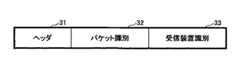
次に、本発明における制御用フォーマットについて説明する。図3は、本発明における制御用フォーマットの一例を示す図である。なお、制御用フォーマットによる制御用信号(パケット)を用いて、例えば受信装置13から信号終端装置12に受信許可リクエストや、信号終端装置12からの受信装置13に対して放送区域内であるか否かの通知等を行う。 Next, the control format in the present invention will be described. FIG. 3 is a diagram showing an example of a control format in the present invention. It should be noted that, using a control signal (packet) in the control format, for example, a reception permission request from the receiving
図3に示す制御用フォーマットは、ヘッダ31と、パケット識別32と、受信装置識別33とを有している。ここで、ヘッダ31は、上述したヘッダ21と同様に宛先アドレスや送信元アドレス等を有している。また、パケット識別32は、受信装置識別33に付加された装置に対する制御の内容を識別するための識別情報を有している。 The control format shown in FIG. 3 includes a
例えば、パケット識別が“1”の場合は、制御用信号が受信装置識別33に示された受信装置から信号終端装置12に対する受信許可リクエストであることを示し、また、パケット識別が“2”の場合は、制御用信号が放送区域内であるか否かを判断して信号終端装置12から受信装置識別33に示された受信装置へ通知する信号(例えば、許可/不許可等)であることを示す。 For example, when the packet identification is “1”, it indicates that the control signal is a reception permission request from the receiving device indicated by the receiving
また、受信装置識別33は、受信装置固有の識別情報(例えば、受信装置13のMACアドレスやIPアドレス等)を用いて対象となる受信装置13を特定する。なお、受信装置識別33には、信号終端装置12の識別情報が付加されることもある。 In addition, the
次に、本発明における信号終端装置12と、受信装置13とにおける具体的な装置構成とその処理動作について説明する。なお、本発明では、信号終端装置12と、受信装置13との線路長を測定するにあたり、信号終端装置12側で測定する場合と受信装置13側で測定する場合とがある。そのため以下の説明では、それぞれについての実施形態について説明する。 Next, specific device configurations and processing operations of the
<第1の実施形態:信号終端装置が受信装置との間の伝搬時間を測定する場合>
<第1の実施形態:信号終端装置>
図4は、第1の実施形態における信号終端装置の一構成例を示す図である。図4に示す信号終端装置40は、第1送受信手段41と、比較手段42と、伝搬時間測定信号生成手段43と、第2送受信手段44と、線路長推定手段45と、分配手段46とを有するよう構成されている。<First Embodiment: When Signal Termination Device Measures Propagation Time with Receiving Device>
<First Embodiment: Signal Termination Device>
FIG. 4 is a diagram illustrating a configuration example of the signal termination device according to the first embodiment. 4 includes a first transmission /
第1送受信手段41は、ヘッドエンドから受信装置に出力するための放送信号(例えば、デジタル放送信号やコンテンツ信号等を含む)を受信する。また、第1送受信手段41は、受信した放送信号を分配手段46に出力する。なお、第1送受信手段41は、比較手段42から得られる線路長と閾値(設定値)との比較結果をヘッドエンド等に送信することもできる。 The first transmission / reception means 41 receives a broadcast signal (for example, including a digital broadcast signal and a content signal) to be output from the head end to the receiving device. The first transmission /
比較手段42は、線路長推定手段45により得られる線路長に基づいて予め設定されている閾値との比較を行う。また、比較手段42は、比較結果を分配手段46に出力する。また、必要に応じて比較結果を第1送受信手段41に出力する。なお、比較手段42は、線路長推定手段45から線路長情報を取得していない場合、閾値との比較ができない。 The comparison means 42 performs comparison with a preset threshold value based on the line length obtained by the line length estimation means 45. Further, the
そのため、比較手段42は、伝搬時間測定信号生成手段43に線路長を測定するための線路長測定リクエストを出力して、伝搬時間測定信号を生成させることで、受信装置との間で伝搬時間測定信号の送受信を行い、線路長推定手段45から線路長を取得することができる。これにより、比較手段42は、所定の時間間隔で定期的に線路長の測定を行うことができる。また、放送信号の提供前や提供時において、受信装置を監視して不正受信等を防止することができる。 Therefore, the comparison means 42 outputs a line length measurement request for measuring the line length to the propagation time measurement signal generation means 43 and generates a propagation time measurement signal, so that the propagation time measurement is performed with the receiving device. Signal transmission / reception is performed, and the line length can be acquired from the line length estimation means 45. Thereby, the comparison means 42 can measure the line length periodically at a predetermined time interval. In addition, it is possible to prevent unauthorized reception by monitoring the receiving device before or at the time of providing the broadcast signal.
伝搬時間測定信号生成手段43は、第2送受信手段44から送られる受信装置からの受信許可リクエストや、比較手段42からの線路長測定リクエストに対して伝搬時間測定信号を生成し、第2送受信手段44に出力する。なお、伝搬時間測定信号生成手段43は、伝搬時間測定信号の出力時に図2に示す“送出装置識別”に信号終端装置の識別情報を付加し、また“装置出力時刻1”に時刻を付加する。 The propagation time measurement
第2送受信手段44は、受信装置から図3に示す制御用信号による受信許可リクエスト信号を受信すると伝搬時間測定信号生成手段43に出力する。また、第2送受信手段44は、伝搬時間測定信号生成手段43より得られる伝搬時間測定信号をリクエストのあった受信装置に出力する。また、第2送受信手段44は、受信装置から受信した伝搬時間測定信号を線路長推定手段45に出力する。更に、第2送受信手段44は、分配手段46より得られる放送信号等を対応する受信装置に出力する。なお、第2送受信手段44は、放送信号と伝搬時間測定信号とを同時に出力する場合は、放送信号と伝搬時間測定信号とを多重化した信号を送信する。 When the second transmission / reception means 44 receives the reception permission request signal by the control signal shown in FIG. 3 from the receiving apparatus, the second transmission / reception means 44 outputs it to the propagation time measurement signal generation means 43. Further, the second transmission / reception means 44 outputs the propagation time measurement signal obtained from the propagation time measurement signal generation means 43 to the receiving apparatus that requested it. The second transmission / reception means 44 outputs the propagation time measurement signal received from the receiving device to the line length estimation means 45. Further, the second transmission / reception means 44 outputs the broadcast signal obtained from the distribution means 46 to the corresponding receiving device. In addition, the 2nd transmission / reception means 44 transmits the signal which multiplexed the broadcast signal and the propagation time measurement signal, when outputting a broadcast signal and the propagation time measurement signal simultaneously.
線路長推定手段45は、第2送受信手段44により得られる伝搬時間測定信号に基づいて線路長を推定する。なお、第1の実施形態における線路長の具体的な推定手法については後述する。また、線路長推定手段45は、推定された線路長を比較手段42に出力する。 The line
分配手段46は、比較手段42により得られる比較結果に基づいて第1送受信手段41により得られる放送信号について受信装置に受信を許可させるか否かを判断し、図3に示す制御用信号を生成して、第2送受信手段44から受信装置に送信する。 Based on the comparison result obtained by the comparison means 42, the distribution means 46 determines whether or not the receiving apparatus is allowed to receive the broadcast signal obtained by the first transmission / reception means 41, and generates the control signal shown in FIG. Then, the data is transmitted from the second transmitting / receiving means 44 to the receiving device.
また、分配手段46は、送信を許可する場合には第2送受信手段44により放送信号を受信装置に送信する。 In addition, the
<第1の実施形態:受信装置>
次に、第1の実施形態における受信装置について説明する。図5は、第1の実施形態における受信装置の一構成例を示す図である。図5に示す受信装置50は、送受信手段51と、受信時刻取得手段52と、分離手段53と、再生手段54と、時刻付加手段55と、起動手段56と、リクエスト生成手段57とを有するよう構成されている。<First Embodiment: Receiving Device>
Next, the receiving device in the first embodiment will be described. FIG. 5 is a diagram illustrating a configuration example of the receiving device according to the first embodiment. 5 includes a transmission /
送受信手段51は、リクエスト生成手段57から得られる受信許可リクエスト信号を信号終端装置40に出力する。また、送受信手段51は、信号終端装置40から得られる伝搬時間測定信号を受信時刻取得手段52に出力する。更に、時刻付加手段55より得られる伝搬時間測定信号を信号終端装置40に出力する。 The transmission / reception means 51 outputs the reception permission request signal obtained from the request generation means 57 to the
受信時刻取得手段52は、送受信手段51より信号が入力された時点の時刻を取得し、その時刻を時刻付加手段55に出力する。また、受信時刻取得手段52は、入力した信号は分離手段57に出力する。 The reception
分離手段53は、入力した信号に含まれる放送信号(MPEG−2 TS)と、伝搬時間測定信号とを分離する。また、分離手段53は、放送信号を再生手段54に出力し、伝搬時間測定信号を時刻付加手段55に出力する。また、再生手段54は、分離手段53により得られる放送信号を再生してユーザに視聴させる。 The separating means 53 separates the broadcast signal (MPEG-2 TS) included in the input signal and the propagation time measurement signal. Further, the separating
また、時刻付加手段55は、分離手段53から得られる伝搬時間測定信号について、受信装置50の識別情報を図2に示す“受信装置識別”に付加し、受信時刻取得手段52により得られる時刻を“装置入力時刻1”に付加する。更に、時刻付加手段55は、伝搬時間測定信号を出力する際に図2に示す“装置出力時刻2”に送出時刻を付加する。また、時刻付加手段55は、時刻情報等を付加した伝搬時間測定信号を信号終端装置40に送信するため送受信手段51に出力する。 Further, the
また、起動手段56は、受信装置50の電源のON/OFFを行う。また、起動手段56は、受信装置50の起動後に、受信許可のリクエストを信号終端装置40に対して行うことができるように、電源ON時の制御情報をリクエスト生成手段57に出力する。これにより、受信許可リクエスト信号に対する特別な操作や指示を行うことなく、迅速に受信許可又は受信不許可等の結果を取得することができる。 The
リクエスト生成手段57は、起動手段56からの制御信号に基づいて、受信許可リクエスト信号を生成し送受信手段51に出力する。また、リクエスト生成手段57は、信号終端装置40に対して所望するチャンネルをリクエストするチャンネルリクエスト信号も生成することができる。 The
<第1の実施形態:線路長の推定手法>
ここで、第1の実施形態に基づく線路長の推定手法について説明する。<First Embodiment: Method for Estimating Line Length>
Here, the line length estimation method based on the first embodiment will be described.
信号終端装置40と受信装置50との間の往復時間RTTは、受信装置の識別情報としての番号をnとし、信号終端装置と受信装置nとの間の片側伝搬時間をtnとし、受信装置での処理時間(伝搬時間測定信号において、装置出力時刻2−装置入力時刻1)をtrnとすると、次式で示される。
RTT=2×tn+trn [sec]
したがって、片側伝搬時間tnは、
tn=(RTT−trn)/2 [sec]
となる。The round-trip time RTT between the
RTT = 2 × tn + trn [sec]
Therefore, the one-side propagation time tn is
tn = (RTT−trn) / 2 [sec]
It becomes.
なお、時刻情報の分解能をマイクロ秒(μsec)にすることにより、線路長の測定の分解能は300メートル単位まで向上させることができる。また、線路長dは、vを伝送速度とし、cを真空中の光速度とし、nを光ファイバーの屈折率とすると、
d=v×tn [m]
で表される(なお、v=c/n,c=3×108 [m/s]とする。)。Note that by setting the resolution of the time information to microseconds (μsec), the resolution of the line length measurement can be improved to a unit of 300 meters. The line length d is defined as follows: v is the transmission speed, c is the speed of light in vacuum, and n is the refractive index of the optical fiber.
d = v × tn [m]
(Note that v = c / n and c = 3 × 10⁸ [m / s]).
また、同軸ケーブルの場合には、cに波長短縮率(例えば、約0.67等)を乗じることにより伝送速度が算出できる(v=c×0.67 [m/s])。 In the case of a coaxial cable, the transmission rate can be calculated by multiplying c by a wavelength shortening rate (for example, about 0.67) (v = c × 0.67 [m / s]).
以上により、受信装置内での処理時間を除いたより高精度な伝送時間を算出することができる。また、信号終端装置と受信装置との間の距離(線路長)を高精度に推定することができる。 As described above, it is possible to calculate a more accurate transmission time excluding the processing time in the receiving apparatus. Further, the distance (line length) between the signal termination device and the receiving device can be estimated with high accuracy.
なお、線路長の推定方法としては、上述した線路長の算出を所定の受信装置に対する複数の伝搬時間測定信号を用いて行い、それぞれ伝搬時間測定信号得られる線路長のうちで、最小値又は平均値を線路長として推定してもよい。これにより、より正確な線路長を推定することができる。 As a method for estimating the line length, the above-described line length calculation is performed using a plurality of propagation time measurement signals for a predetermined receiving device, and the minimum or average of the line lengths obtained from the propagation time measurement signals, respectively. The value may be estimated as the line length. As a result, a more accurate line length can be estimated.
<第1の実施形態:出力制御処理>
次に、第1の実施形態における信号終端装置の出力制御処理について、フローチャートを用いて説明する。図6は、第1の実施形態における信号終端装置の出力制御処理の一例を示すフローチャートである。なお、図6では、信号終端装置が、受信装置との間の伝搬時間を測定して放送区域内であるか否かを判断し、放送区域内にあるときには放送信号の出力を行う形態を示すものである。<First Embodiment: Output Control Processing>
Next, output control processing of the signal termination device in the first embodiment will be described using a flowchart. FIG. 6 is a flowchart illustrating an example of output control processing of the signal termination device according to the first embodiment. FIG. 6 shows a mode in which the signal termination device measures the propagation time with the receiving device to determine whether or not it is within the broadcast area, and outputs the broadcast signal when it is within the broadcast area. Is.
まず、受信装置の電源を投入された際に信号終端装置に対して受信許可を得るため、上述の図3に示す受信許可リクエスト信号を受信する(S01)。次に、図2に示す伝搬時間測定信号を生成し(S02)、生成した図2に示す伝搬時間測定信号を、リクエスト信号を送信した受信装置に対して出力する(S03)。その際、伝搬時間測定信号に図2に示す“送出装置識別”に信号終端装置の識別情報を付加し、“装置出力時刻1”に送出時刻を付加する。 First, in order to obtain reception permission for the signal termination device when the power of the receiving device is turned on, the reception permission request signal shown in FIG. 3 is received (S01). Next, the propagation time measurement signal shown in FIG. 2 is generated (S02), and the generated propagation time measurement signal shown in FIG. 2 is output to the receiving apparatus that transmitted the request signal (S03). At that time, the signal termination device identification information is added to the “transmission device identification” shown in FIG. 2 and the transmission time is added to “device output time 1” in the propagation time measurement signal.
次に、信号終端装置は、受信装置において“受信装置識別”、“装置入力時刻1”、及び“装置出力時刻2”が付加された伝搬時間測定信号を受信する(S04)。このとき、伝搬時間測定信号に“装置入力時刻2”を付加してもよい。 Next, the signal terminating device receives the propagation time measurement signal to which “receiving device identification”, “device input time 1”, and “device output time 2” are added in the receiving device (S04). At this time, “device input time 2” may be added to the propagation time measurement signal.
次に、信号終端装置は、伝搬時間測定信号に付加された時刻情報等により伝送時間を算出し、線路長を推定する(S05)。また、S05にて取得した線路長に基づいて受信装置が放送対象区域内にあるか否かを判断する(S06)。具体的には、例えば、S05により推定された線路長と予め設定された閾値(例えば、500m等)とを比較し、閾値以下である場合は、受信装置が放送対象区域内にあるものとし、閾値を超える場合は、放送対象範囲内にないとすることにより判断を行う。 Next, the signal termination device calculates the transmission time based on the time information added to the propagation time measurement signal and estimates the line length (S05). Further, based on the track length acquired in S05, it is determined whether or not the receiving device is in the broadcast target area (S06). Specifically, for example, the line length estimated in S05 is compared with a preset threshold value (for example, 500 m or the like), and if it is equal to or less than the threshold value, the receiving device is assumed to be in the broadcast target area, If it exceeds the threshold, it is determined that it is not within the broadcast target range.
ここで、S06において、放送対象区域内にある場合(S06において、YES)、図3に示す制御用信号のフォーマットに基づいて受信許可信号を生成して受信許可リクエストのあった受信装置に出力する(S07)。また、受信許可に基づいて放送信号の出力を行うこともできる(S08)。 Here, in S06, when it is within the broadcast target area (YES in S06), a reception permission signal is generated based on the format of the control signal shown in FIG. 3, and is output to the receiving apparatus that has received the reception permission request. (S07). Also, it is possible to output a broadcast signal based on the reception permission (S08).
また、S06において、放送対象範囲内にない場合(S06において、NO)、図3に示す制御用信号のフォーマットに基づいて受信不許可信号を出力する(S09)。 In S06, if it is not within the broadcast target range (NO in S06), a reception non-permission signal is output based on the format of the control signal shown in FIG. 3 (S09).
これにより、線路長を高精度に推定することができる。また、推定された線路長の情報に基づいてデジタル放送等の受信動作を有効とするか否か等を判断することができ、放送区域内に限定して動作する受信装置を提供することができる。 Thereby, the line length can be estimated with high accuracy. In addition, it is possible to determine whether or not the receiving operation of digital broadcasting or the like is valid based on the estimated line length information, and it is possible to provide a receiving device that operates only within a broadcasting area. .
ここで、第1の実施形態は、信号終端装置により出力制御を行っているが、本発明においてはこの限りではなく、例えば受信装置で伝搬時間測定信号の生成、閾値との比較、出力制御等の処理を行うこともできる。次に、上述の内容を第2の実施形態として、装置構成及び処理内容について、図を用いて説明する。 Here, in the first embodiment, the output control is performed by the signal termination device. However, the present invention is not limited to this. For example, the reception device generates a propagation time measurement signal, compares it with a threshold value, outputs control, and the like. Can also be performed. Next, the apparatus configuration and processing contents will be described with reference to the drawings with the above-described contents as a second embodiment.
<第2の実施形態:受信装置が信号終端装置との間の伝搬時間を測定する場合>
<第2の実施形態:信号終端装置>
図7は、第2の実施形態における信号終端装置の一構成例を示す図である。図7に示す信号終端装置70は、受信手段71と、分配手段72と、送受信手段73と、時刻付加手段74とを有するよう構成されている。<Second Embodiment: When Receiving Device Measures Propagation Time with Signal Terminating Device>
<Second Embodiment: Signal Termination Device>
FIG. 7 is a diagram illustrating a configuration example of the signal termination device according to the second embodiment. The
受信手段71は、ヘッドエンドから所定の放送信号を受信する。また、受信手段71は、受信した放送信号を分配手段72に出力する。 The receiving means 71 receives a predetermined broadcast signal from the head end. The receiving means 71 outputs the received broadcast signal to the distributing
分配手段72は、受信手段71から得られる放送信号を送信可能な受信装置の全てについて送信するため、各受信装置のアドレス情報に基づいて送受信手段73に出力する。 The distributing means 72 outputs the broadcast signal obtained from the receiving means 71 to all the receiving apparatuses that can transmit it, and outputs it to the transmitting / receiving means 73 based on the address information of each receiving apparatus.
送受信手段73は、受信装置から得られる伝搬時間測定信号を受信すると、その信号を時刻付加手段74に出力する。また、送受信手段73は、時刻付加手段74により得られる伝搬時間測定信号を受信装置に出力する。また、送受信手段73は、放送信号と伝搬時間測定信号とを同時に出力する場合は、放送信号と伝搬時間測定信号とを多重化した信号を送信する。 When receiving the propagation time measurement signal obtained from the receiving device, the transmission / reception means 73 outputs the signal to the time addition means 74. The transmission / reception means 73 outputs the propagation time measurement signal obtained by the time addition means 74 to the receiving device. The transmission / reception means 73 transmits a signal obtained by multiplexing the broadcast signal and the propagation time measurement signal when outputting the broadcast signal and the propagation time measurement signal simultaneously.
時刻付加手段74は、送受信手段73より得られる伝搬時間測定信号に対して信号終端装置の識別情報を図2に示す“受信装置識別”に付加し、また、入力時刻を“装置入力時刻1”に付加し、出力時刻を“装置出力時刻2”に付加して、送受信手段73に出力する。 The
<第2の実施形態:受信装置>
次に、第2の実施形態における受信装置の構成について説明する。図8は、第2の実施形態における受信装置の一構成例を示す図である。図8に示す受信装置80は、送受信手段81と、分離手段82と、再生制御手段83と、再生手段84と、線路長推定手段85と、比較手段86と、起動手段87と、伝搬時間測定信号生成手段88とを有するよう構成されている。Second Embodiment: Receiving Device
Next, the configuration of the receiving apparatus in the second embodiment will be described. FIG. 8 is a diagram illustrating a configuration example of the receiving device according to the second embodiment. 8 includes a transmission /
送受信手段81は、伝搬時間測定信号生成手段88から得られる伝搬時間測定信号を信号終端装置81に出力する。また、送受信手段81は、信号終端装置から得られる信号を分離手段82に出力する。 The transmission / reception means 81 outputs the propagation time measurement signal obtained from the propagation time measurement signal generation means 88 to the
分離手段82は、入力した信号を伝搬時間測定信号と放送信号(MPEG−2 TS)に分離し、伝搬時間測定信号を線路長推定手段85に出力し、放送信号を再生制御手段83に出力する。 The separating means 82 separates the input signal into a propagation time measurement signal and a broadcast signal (MPEG-2 TS), outputs the propagation time measurement signal to the line length estimation means 85, and outputs the broadcast signal to the reproduction control means 83. .
再生制御手段83は、分離手段82により得られる放送信号を比較手段86から得られる比較結果に基づいて再生手段84に出力するか否かを判断する。また、再生制御手段83は、比較の結果、放送信号を再生することが可能である場合には、再生手段84に放送信号を出力する。また、再生手段84は、再生制御手段83により得られる放送信号を再生してユーザに視聴させる。 The
線路長推定手段85は、分離手段82により得られる伝搬時間測定信号に基づいて線路長を推定する。なお、第2の実施形態における線路長の具体的な推定手法については後述する。 The line
比較手段86は、線路長推定手段85により得られる線路長に基づいて受信装置80に予め設定されている閾値との比較を行う。また、比較結果を再生制御手段83に出力する。 The
起動手段87は、受信装置80の電源のON/OFFを行う。また、起動手段87は、受信装置80の起動後に,受信許可のリクエストを信号終端装置70に対して行うことができるように、電源ON時の制御情報を伝搬時間測定信号生成手段88に出力する。これにより、受信許可リクエスト信号に対する特別な操作や指示を行うことなく、迅速に受信許可又は受信不許可等の結果を取得することができる。 The
伝搬時間測定信号生成手段88は、起動手段87により得られる制御情報により図2に示す伝搬時間測定信号を生成し、送受信手段81に出力する。なお、このとき、図2に示す伝搬時間測定信号の“送出装置識別”に受信装置の識別情報を付加し、“装置出力時刻1”に送出時刻を付加する。 The propagation time measurement signal generation means 88 generates the propagation time measurement signal shown in FIG. 2 based on the control information obtained by the activation means 87 and outputs it to the transmission / reception means 81. At this time, the identification information of the receiving device is added to “transmission device identification” of the propagation time measurement signal shown in FIG. 2, and the transmission time is added to “device output time 1”.
<第2の実施形態:線路長の推定手法>
次に、第2の実施形態における線路長の推定手法について具体的に説明する。<Second Embodiment: Method for Estimating Line Length>
Next, the line length estimation method in the second embodiment will be specifically described.
受信装置80と、信号終端装置70間の往復時間RTTは、nを受信装置の識別情報としての番号とし、tnを信号終端装置と受信装置nとの間の片側伝搬時間とし、teを信号終端装置での処理時間(伝搬時間測定信号において、装置出力時刻2−装置入力時刻1)とすると、
RTT=2×tn+te [sec]
となる。したがって、片側伝搬時間tnは、
tn=(RTT−te)/2 [sec]
となる。これにより、線路長は
d=v×tn [m]
となる。The round-trip time RTT between the receiving
RTT = 2 × tn + te [sec]
It becomes. Therefore, the one-side propagation time tn is
tn = (RTT-te) / 2 [sec]
It becomes. As a result, the line length is d = v × tn [m].
It becomes.
また、受信装置が放送区域内であるか否かを判断するために、上述したように推定された線路長dと、閾値との比較を行い、比較結果が放送区域内と判断された場合、受信装置はデジタル放送等の放送信号の再生が可能となる。 Further, in order to determine whether or not the receiving device is within the broadcast area, the line length d estimated as described above is compared with a threshold value, and if the comparison result is determined to be within the broadcast area, The receiving device can reproduce broadcast signals such as digital broadcasts.
<第2の実施形態:出力制御処理>
次に、第2の実施形態における受信装置の出力制御処理について、フローチャートを用いて説明する。図9は、第2の実施形態における受信装置の出力制御処理の一例を示すフローチャートである。なお、図9では、受信装置が信号終端装置との伝搬時間を測定して放送区域内であるか否かを判断し、放送区域内にあるときには受信装置の再生動作を可能とする場合の形態を示すものである。<Second Embodiment: Output Control Processing>
Next, the output control process of the receiving apparatus in the second embodiment will be described using a flowchart. FIG. 9 is a flowchart illustrating an example of output control processing of the receiving device according to the second embodiment. In FIG. 9, the receiving device measures the propagation time with the signal terminating device to determine whether or not it is in the broadcasting area, and when it is in the broadcasting area, the receiving device can perform the reproduction operation. Is shown.
まず、受信装置の電源がONされ受信装置が起動する(S21)。次に、受信可能であるか否かを判断するため、図2に示す伝搬時間測定信号を生成し(S22)、生成した伝搬時間測定信号を信号終端装置に出力する(S23)。その際、伝搬時間測定信号に図2に示す“送出装置識別”に受信装置の識別情報を付加し、“装置出力時刻1”に送出時刻を付加する。 First, the power of the receiving device is turned on and the receiving device is activated (S21). Next, in order to determine whether or not reception is possible, the propagation time measurement signal shown in FIG. 2 is generated (S22), and the generated propagation time measurement signal is output to the signal termination device (S23). At that time, the identification information of the receiving device is added to “transmission device identification” shown in FIG. 2 and the transmission time is added to “device output time 1” in the propagation time measurement signal.
次に、信号終端装置において“受信装置識別”、“装置入力時刻1”、及び“装置出力時刻2”が付加された伝搬時間測定信号を受信する(S24)。このとき、伝搬時間測定信号に“装置入力時刻2”を付加してもよい。 Next, the signal termination device receives the propagation time measurement signal to which “reception device identification”, “device input time 1”, and “device output time 2” are added (S24). At this time, “device input time 2” may be added to the propagation time measurement signal.
次に、受信装置は、伝搬時間測定信号に付加された時刻情報等により伝送時間を算出し、線路長を推定する(S25)。また、S25にて取得した線路長に基づいて受信装置が放送対象区域内にあるか否かを判断する(S26)。 Next, the receiving device calculates the transmission time based on the time information added to the propagation time measurement signal and estimates the line length (S25). Further, it is determined whether or not the receiving device is within the broadcast target area based on the track length acquired in S25 (S26).
ここで、S26において、放送対象区域内にある場合(S26において、YES)、放送信号の再生を行う(S27)。また、S26にて、放送対象範囲内にない場合(S26において、YES)、処理を終了する。 Here, in S26, when it is in the broadcast target area (YES in S26), the broadcast signal is reproduced (S27). In S26, when it is not within the broadcast target range (YES in S26), the process is terminated.
これにより、線路長を高精度に推定することができる。また、推定された線路長の情報に基づいてデジタル放送等の受信動作を有効とするか否か、つまり、信号を再生するか否かを判断することができ、放送区域内に限定して動作する受信装置を提供することができる。 Thereby, the line length can be estimated with high accuracy. Also, based on the estimated line length information, it can be determined whether or not the receiving operation such as digital broadcasting is valid, that is, whether or not the signal is reproduced. A receiving device can be provided.
ここで、本発明における信号終端装置及び受信装置は、上述した専用の装置構成等を用いて本発明における出力制御処理を行うこともできるが、各構成における処理をコンピュータに実行させることができる実行プログラムを生成し、例えば、汎用のパーソナルコンピュータ、ワークステーション等にそのプログラムをインストールすることにより、上述した第1又は第2の実施形態における出力制御処理を実現することができる。 Here, the signal termination device and the receiving device according to the present invention can perform the output control processing according to the present invention by using the above-described dedicated device configuration, etc., but can execute the processing in each configuration by the computer. By generating the program and installing the program in, for example, a general-purpose personal computer or workstation, the output control process in the first or second embodiment described above can be realized.
<ハードウェア構成>
ここで、本発明における出力制御処理が実行可能なコンピュータのハードウェア構成例について図を用いて説明する。図10は、本発明における出力制御処理が実現可能なハードウェア構成の一例を示す図である。<Hardware configuration>
Here, a hardware configuration example of a computer capable of executing the output control processing according to the present invention will be described with reference to the drawings. FIG. 10 is a diagram illustrating an example of a hardware configuration capable of realizing the output control process according to the present invention.
図10におけるコンピュータ本体には、入力装置91と、出力装置92と、ドライブ装置93と、補助記憶装置94と、メモリ装置95と、各種制御を行うCPU(Central Processing Unit)96と、ネットワーク接続装置97とを有するよう構成されており、これらはシステムバスBで相互に接続されている。 10 includes an
入力装置91は、ユーザが操作するキーボード及びマウス等のポインティングデバイスを有しており、ユーザからのプログラムの実行等、各種操作信号を入力する。出力装置92は、本発明における処理を行うためのコンピュータ本体を操作するのに必要な各種ウィンドウやデータ等を表示するディスプレイ(モニタ)を有し、CPU96が有する制御プログラムにより出力制御プログラムの実行経過や結果等を表示することができる。 The
ここで、本発明において、コンピュータ本体にインストールされる実行プログラムは、例えば、CD−ROM等の記録媒体98等により提供される。プログラムを記録した記録媒体98は、ドライブ装置93にセット可能であり、記録媒体98に含まれる実行プログラムが、記録媒体98からドライブ装置93を介して補助記憶装置94にインストールされる。 Here, in the present invention, the execution program installed in the computer main body is provided by, for example, a
補助記憶装置94は、ハードディスク等のストレージ手段であり、本発明における実行プログラムや、コンピュータに設けられた制御プログラム等を蓄積し必要に応じて入出力を行うことができる。 The
CPU96は、OS(Operating System)等の制御プログラム、及びメモリ装置95により読み出され格納されている実行プログラムに基づいて、各種演算や各ハードウェア構成部とのデータの入出力等、コンピュータ全体の処理を制御して、出力制御処理における各処理を実現することができる。プログラムの実行中に必要な各種情報等は、補助記憶装置94から取得することができ、また格納することもできる。 Based on a control program such as an OS (Operating System) and an execution program read and stored by the
ネットワーク接続装置97は、通信ネットワーク等と接続することにより、実行プログラムを通信ネットワークに接続されている他の端末等から取得したり、プログラムを実行することで得られた実行結果又は本発明における実行プログラム自体を他の端末等に提供することができる。 The
上述したようなハードウェア構成により、特別な装置構成を必要とせず、低コストで上述した出力制御処理を実現することができる。また、プログラムをインストールすることにより、容易に出力制御処理を実現することができる。 With the hardware configuration as described above, the above-described output control processing can be realized at a low cost without requiring a special device configuration. Moreover, the output control process can be easily realized by installing the program.
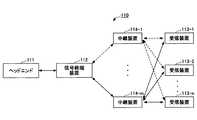
なお、本発明においては、図1に示す分配システムの構成の他にルータ等の中継装置を介して信号終端装置と受信装置とが接続される場合がある。この場合には、伝送時間測定信号に中継される中継装置毎の入出力時刻及び識別情報を付加する。ここで、上述のシステム構成例について図を用いて説明する。図11は、本発明を適用した中継装置を有する分配伝送システムのシステム構成の一例を示す図である。なお、図11では、図1と同様に有線系の分配伝送の一例としてケーブルテレビにおける放送信号の分配伝送を示している。 In the present invention, in addition to the configuration of the distribution system shown in FIG. 1, the signal termination device and the receiving device may be connected via a relay device such as a router. In this case, the input / output time and identification information for each relay device to be relayed are added to the transmission time measurement signal. Here, the above-described system configuration example will be described with reference to the drawings. FIG. 11 is a diagram illustrating an example of a system configuration of a distribution transmission system having a relay device to which the present invention is applied. In addition, in FIG. 11, the broadcast signal distribution transmission in a cable television is shown as an example of wired distribution transmission similarly to FIG.
図11に示す有線分配システム110は、ヘッドエンド111と、加入者信号終端装置112と、受信装置113−1〜113−nと、中継装置114−1〜114−mとを有するよう構成されている。なお、図11では、ヘッドエンド111及び加入者信号終端装置112を1つ有し、受信装置113及び中継装置114を複数有しているが、構成については、これに限定されることはなく、各装置が少なくとも1つ有していればよい。 The
図11において、中継装置114−1〜114−mは、それぞれ信号終端装置112及び複数の受信装置113と接続可能であり、線路上の伝送負荷等の影響により、中継装置114が変更されて最適な経路で伝送が行われる。 In FIG. 11, the relay devices 114-1 to 114-m can be connected to the
このような構成の場合は、図12に示す中継装置を介して伝送される伝搬時間測定信号の例に示すように、中継装置114が伝搬時間測定信号を受信及び送信した際に、その中継装置の識別情報、入力時刻、出力時刻の組を伝搬時間測定信号に付加する。この付加した情報に基づいて、予め設定された閾値とを対応させておくことにより、より高精度に線路長との比較を実現することができる。また、中継装置114における処理時間を含まない高精度な伝搬時間を測定することができ、また、伝搬時間から線路長を推定することができる。なお、中継装置の識別情報、入力時刻、出力時刻の組は中継される中継装置の数に対応して随時付加される。 In the case of such a configuration, when the
上述したように本発明によれば、信号終端装置と受信装置との距離(線路長)を高精度に推定し、所定の区域内で放送等の提供を実現することができる。つまり、線路長の情報に基づいて放送信号の受信動作を有効とするか否か又は信号を再生するか否かを判断することができ、放送区域内に限定して動作する受信装置を提供することができる。 As described above, according to the present invention, it is possible to estimate the distance (line length) between the signal termination device and the receiving device with high accuracy, and to provide broadcasting or the like within a predetermined area. In other words, it is possible to determine whether or not to enable broadcast signal reception operation or to reproduce a signal based on the track length information, and to provide a reception device that operates only within a broadcast area. be able to.
なお、上述した実施形態は、有線系の分配伝送システムについて説明しているが、本発明においてはこの限りではなく、無線系においても適用することができる。なお、無線系の伝送システムには、信号終端装置という概念が存在しないため、信号終端装置を中継装置に読み替えることで、容易に適用することができる。 In addition, although embodiment mentioned above has demonstrated the wired distribution transmission system, it is not restricted to this in this invention, It can apply also to a radio | wireless system. In addition, since the concept of a signal termination device does not exist in a wireless transmission system, it can be easily applied by replacing the signal termination device with a relay device.
以上本発明の好ましい実施形態について詳述したが、本発明は係る特定の実施形態に限定されるものではなく、特許請求の範囲に記載された本発明の要旨の範囲内において、種々の変形、変更が可能である。 Although the preferred embodiment of the present invention has been described in detail above, the present invention is not limited to the specific embodiment, and various modifications, within the scope of the gist of the present invention described in the claims, It can be changed.
10,110 分配伝送システム
11,111 ヘッドエンド
12,40,70,112 信号終端装置
13,50,80,113 受信装置
21,31 ヘッダ
22 データ
32 パケット識別
33 受信装置識別
41 第1送受信手段
42,86 比較手段
43,88 伝搬時間測定信号生成手段
44 第2送受信手段
45,85 線路長推定手段
46,72 分配手段
51,73,81 送受信手段
52 受信時刻取得手段
53,82 分離手段
54,84 再生手段
55 時刻付加手段
56,87 起動手段
57 リクエスト生成手段
71 受信手段
83 再生制御手段
91 入力装置
92 出力装置
93 ドライブ装置
94 補助記憶装置
95 メモリ装置
96 CPU
97 ネットワーク接続装置
98 記録媒体
114 中継装置10, 110 Distributed
97
Claims (3)
Translated fromJapanese前記受信装置と前記信号終端装置とにおける信号の伝搬時間を測定するための伝搬時間測定信号を生成する伝搬時間測定信号生成手段と、
前記伝搬時間測定信号生成手段により得られる伝搬時間測定信号を前記信号終端装置に送信し、前記信号終端装置から送信した前記伝搬時間測定信号を受信する送受信手段と、
前記送受信手段により得られる前記伝搬時間測定信号に基づいて、前記信号終端装置と前記受信装置との線路長を推定するための線路長推定手段と、
前記線路長推定手段により得られる線路長と、予め設定された閾値とを比較する比較手段と、
前記比較手段により得られる比較結果に基づいて、前記信号終端装置から得られる前記放送信号の再生制御を行う再生制御手段とを有することを特徴とする受信装置。In a receiving device that receives a broadcast signal distributed and output from a signal termination device,
A propagation time measurement signal generating means for generating a propagation time measurement signal for measuring a propagation time of a signal in the receiving device and the signal terminating device;
A transmission / reception means for transmitting the propagation time measurement signal obtained by the propagation time measurement signal generating means to the signal termination device and receiving the propagation time measurement signal transmitted from the signal termination device;
Based on the propagation time measurement signal obtained by the transmission / reception means, line length estimation means for estimating the line length of the signal termination device and the reception device;
Comparison means for comparing the line length obtained by the line length estimation means with a preset threshold value;
Receiving apparatuscomprising: reproduction control means for performing reproduction control of the broadcast signal obtained from the signal terminating device based on a comparison result obtained by the comparing means .
前記伝搬時間測定信号生成手段は、
前記起動手段からの制御信号に基づいて前記伝搬時間測定信号を生成することを特徴とする請求項1に記載の受信装置。Starting means for starting the receiving device;
The propagation time measurement signal generating means includes
The receiving apparatus according to claim1 , wherein the propagation time measurement signal is generated based on a control signal from the activation unit.
前記受信装置のコンピュータを、
前記受信装置と前記信号終端装置とにおける信号の伝搬時間を測定するための伝搬時間測定信号を生成する伝搬時間測定信号生成手段、
前記伝搬時間測定信号生成手段により得られる伝搬時間測定信号を前記信号終端装置に送信し、前記信号終端装置から送信した前記伝搬時間測定信号を受信する送受信手段、
前記送受信手段により得られる前記伝搬時間測定信号に基づいて、前記信号終端装置と前記受信装置との線路長を推定するための線路長推定手段、
前記線路長推定手段により得られる線路長と、予め設定された閾値とを比較する比較手段、及び、
前記比較手段により得られる比較結果に基づいて、前記信号終端装置から得られる前記放送信号の再生制御を行う再生制御手段として機能させるための出力制御プログラム。An output control programin the receiving device for controlling the output of the broadcast signal based on a line length of a signal terminating device for distributing and outputting the broadcast signal and a receiving device receiving the signal from the signal terminating device In
A computer of the receiving device;
A propagation time measurement signal generatingmeans for generating a propagation time measurement signal for measuring a propagation time of a signal in the receiving device and the signal termination device;
A transmission / receptionmeansfor transmitting the propagation time measurement signal obtained by the propagation time measurement signal generatingmeans to thesignal termination device and receiving the propagation time measurement signal transmitted from the signal termination device ;
Based on the propagation time measurement signal obtained by the transmission / receptionmeans , line length estimationmeans for estimating the line length of the signal termination device and the reception device,
Comparisonmeans for comparing the line length obtained by the line length estimationmeans with a preset threshold value; and
An output control programfor functioning as reproduction control means for performing reproduction control of the broadcast signal obtained from the signal termination device based on a comparison result obtained by the comparison means .
Priority Applications (1)
| Application Number | Priority Date | Filing Date | Title |
|---|---|---|---|
| JP2004352835AJP4392334B2 (en) | 2004-12-06 | 2004-12-06 | Reception device and output control program in the reception device |
Applications Claiming Priority (1)
| Application Number | Priority Date | Filing Date | Title |
|---|---|---|---|
| JP2004352835AJP4392334B2 (en) | 2004-12-06 | 2004-12-06 | Reception device and output control program in the reception device |
Publications (2)
| Publication Number | Publication Date |
|---|---|
| JP2006165872A JP2006165872A (en) | 2006-06-22 |
| JP4392334B2true JP4392334B2 (en) | 2009-12-24 |
Family
ID=36667403
Family Applications (1)
| Application Number | Title | Priority Date | Filing Date |
|---|---|---|---|
| JP2004352835AExpired - Fee RelatedJP4392334B2 (en) | 2004-12-06 | 2004-12-06 | Reception device and output control program in the reception device |
Country Status (1)
| Country | Link |
|---|---|
| JP (1) | JP4392334B2 (en) |
Families Citing this family (2)
| Publication number | Priority date | Publication date | Assignee | Title |
|---|---|---|---|---|
| KR101203469B1 (en)* | 2006-02-11 | 2012-11-21 | 삼성전자주식회사 | Method to accurately and securely measure propagation delay and distance between sending and receiving node in packet network using cut-through approach and packet network node for executing the method |
| US8233432B2 (en)* | 2007-08-31 | 2012-07-31 | Silicon Image, Inc. | Ensuring physical locality of entities sharing data |
- 2004
- 2004-12-06JPJP2004352835Apatent/JP4392334B2/ennot_activeExpired - Fee Related
Also Published As
| Publication number | Publication date |
|---|---|
| JP2006165872A (en) | 2006-06-22 |
Similar Documents
| Publication | Publication Date | Title |
|---|---|---|
| US11736369B2 (en) | Resource measurement and management | |
| US20230412894A1 (en) | Optimized Delivery Techniques | |
| EP2665261A1 (en) | Content reproduction device, content reproduction method, delivery system, content reproduction program, recording medium, and data structure | |
| KR100739734B1 (en) | Method and apparatus for providing additional information of digital broadcasting program through IPTV of home network | |
| US20080134267A1 (en) | Remote Access to Internet Protocol Television by Enabling Place Shifting Utilizing a Telephone Company Network | |
| JP2008113301A (en) | Video transmission apparatus and video transmission method | |
| US10432696B2 (en) | Transmitting apparatus, transmitting method, receiving apparatus, receiving method, program, and content distribution system | |
| KR101769115B1 (en) | System, media play device and server for providing cue-tone advertisement service | |
| JP2008236742A (en) | Method of providing quality of service in network, intermediate node device, and system | |
| JP5301011B1 (en) | Content transmission apparatus and content transmission method | |
| JP4282686B2 (en) | COMMUNICATION DEVICE, METHOD, AND PROGRAM | |
| JP4392334B2 (en) | Reception device and output control program in the reception device | |
| US9800921B2 (en) | In-home smart video cache | |
| KR100677614B1 (en) | Method and apparatus for transmitting digital broadcasting side information in home network | |
| JP5082715B2 (en) | Receiving device, receiving method, and computer program | |
| US20110280546A1 (en) | Time-shifted viewing system, time-shifted viewing method, and time-shifted viewing apparatus and program | |
| JP2009118361A (en) | Communication control device and communication control method | |
| US20230336817A1 (en) | Customer premises equipment with a network probe and a method for monitoring quality of service in an iptv content delivery network | |
| KR102440378B1 (en) | Terrestrial UHD broadcasting optimization method and system | |
| US20100058424A1 (en) | System and method for controlling signal traffic peaks on a video interactive network | |
| JP2009124433A (en) | Stream supply apparatus, content reproduction apparatus, and content reproduction method. | |
| JP2011010238A (en) | Packet transfer quality control system and method | |
| JP2010288165A (en) | Video / audio relay device |
Legal Events
| Date | Code | Title | Description |
|---|---|---|---|
| A621 | Written request for application examination | Free format text:JAPANESE INTERMEDIATE CODE: A621 Effective date:20070409 | |
| A977 | Report on retrieval | Free format text:JAPANESE INTERMEDIATE CODE: A971007 Effective date:20090421 | |
| A131 | Notification of reasons for refusal | Free format text:JAPANESE INTERMEDIATE CODE: A131 Effective date:20090428 | |
| A521 | Written amendment | Free format text:JAPANESE INTERMEDIATE CODE: A523 Effective date:20090618 | |
| TRDD | Decision of grant or rejection written | ||
| A01 | Written decision to grant a patent or to grant a registration (utility model) | Free format text:JAPANESE INTERMEDIATE CODE: A01 Effective date:20090915 | |
| A01 | Written decision to grant a patent or to grant a registration (utility model) | Free format text:JAPANESE INTERMEDIATE CODE: A01 | |
| A61 | First payment of annual fees (during grant procedure) | Free format text:JAPANESE INTERMEDIATE CODE: A61 Effective date:20091009 | |
| FPAY | Renewal fee payment (event date is renewal date of database) | Free format text:PAYMENT UNTIL: 20121016 Year of fee payment:3 | |
| R150 | Certificate of patent or registration of utility model | Free format text:JAPANESE INTERMEDIATE CODE: R150 | |
| FPAY | Renewal fee payment (event date is renewal date of database) | Free format text:PAYMENT UNTIL: 20121016 Year of fee payment:3 | |
| FPAY | Renewal fee payment (event date is renewal date of database) | Free format text:PAYMENT UNTIL: 20131016 Year of fee payment:4 | |
| FPAY | Renewal fee payment (event date is renewal date of database) | Free format text:PAYMENT UNTIL: 20141016 Year of fee payment:5 | |
| R250 | Receipt of annual fees | Free format text:JAPANESE INTERMEDIATE CODE: R250 | |
| LAPS | Cancellation because of no payment of annual fees |