JP4391839B2 - Shooting condition setting program, shooting condition setting method, and shooting condition setting apparatus - Google Patents
Shooting condition setting program, shooting condition setting method, and shooting condition setting apparatusDownload PDFInfo
- Publication number
- JP4391839B2 JP4391839B2JP2004023164AJP2004023164AJP4391839B2JP 4391839 B2JP4391839 B2JP 4391839B2JP 2004023164 AJP2004023164 AJP 2004023164AJP 2004023164 AJP2004023164 AJP 2004023164AJP 4391839 B2JP4391839 B2JP 4391839B2
- Authority
- JP
- Japan
- Prior art keywords
- traveling direction
- moving body
- lane
- condition setting
- shooting
- Prior art date
- Legal status (The legal status is an assumption and is not a legal conclusion. Google has not performed a legal analysis and makes no representation as to the accuracy of the status listed.)
- Expired - Fee Related
Links
Images


Classifications
- G—PHYSICS
- G06—COMPUTING OR CALCULATING; COUNTING
- G06T—IMAGE DATA PROCESSING OR GENERATION, IN GENERAL
- G06T7/00—Image analysis
- G06T7/20—Analysis of motion
- G—PHYSICS
- G06—COMPUTING OR CALCULATING; COUNTING
- G06V—IMAGE OR VIDEO RECOGNITION OR UNDERSTANDING
- G06V20/00—Scenes; Scene-specific elements
- G06V20/50—Context or environment of the image
- G06V20/52—Surveillance or monitoring of activities, e.g. for recognising suspicious objects
- G06V20/54—Surveillance or monitoring of activities, e.g. for recognising suspicious objects of traffic, e.g. cars on the road, trains or boats
- G—PHYSICS
- G06—COMPUTING OR CALCULATING; COUNTING
- G06V—IMAGE OR VIDEO RECOGNITION OR UNDERSTANDING
- G06V20/00—Scenes; Scene-specific elements
- G06V20/60—Type of objects
- G06V20/62—Text, e.g. of license plates, overlay texts or captions on TV images
- G06V20/63—Scene text, e.g. street names
- G—PHYSICS
- G08—SIGNALLING
- G08G—TRAFFIC CONTROL SYSTEMS
- G08G1/00—Traffic control systems for road vehicles
- G08G1/01—Detecting movement of traffic to be counted or controlled
- G08G1/017—Detecting movement of traffic to be counted or controlled identifying vehicles
- G08G1/0175—Detecting movement of traffic to be counted or controlled identifying vehicles by photographing vehicles, e.g. when violating traffic rules
- G—PHYSICS
- G06—COMPUTING OR CALCULATING; COUNTING
- G06V—IMAGE OR VIDEO RECOGNITION OR UNDERSTANDING
- G06V20/00—Scenes; Scene-specific elements
- G06V20/60—Type of objects
- G06V20/62—Text, e.g. of license plates, overlay texts or captions on TV images
- G06V20/625—License plates
Landscapes
- Engineering & Computer Science (AREA)
- Physics & Mathematics (AREA)
- General Physics & Mathematics (AREA)
- Multimedia (AREA)
- Theoretical Computer Science (AREA)
- Computer Vision & Pattern Recognition (AREA)
- Traffic Control Systems (AREA)
- Image Analysis (AREA)
- Closed-Circuit Television Systems (AREA)
Description
Translated fromJapaneseこの発明は、移動体を識別する識別情報に係る画像の撮影条件を設定する撮影条件設定プログラム、撮影条件設定方法および撮影条件設定装置に関し、特に、車両などの移動体の進行方向が変化する場合に移動体を識別する識別情報の撮影条件を適切に設定することができる撮影条件設定プログラム、撮影条件設定方法および撮影条件設定装置に関するものである。 The present invention relates to a shooting condition setting program, a shooting condition setting method, and a shooting condition setting device for setting a shooting condition of an image related to identification information for identifying a moving body, and in particular, when the traveling direction of a moving body such as a vehicle changes. The present invention relates to an imaging condition setting program, an imaging condition setting method, and an imaging condition setting apparatus that can appropriately set an imaging condition of identification information for identifying a moving body.
従来、自動車などの車両の交通監視を目的に、車両のナンバープレートに記された登録情報を読み取る交通監視システムが利用されている。この交通監視システムにおいては、カメラで撮影したナンバープレートの登録情報に対して文字認識処理を実行し、その結果を撮影場所や撮影時刻の情報とともにデータベースに蓄えることにより、特定の登録情報を有する車両がいつどこを走行していたかを容易に検索することができる。 2. Description of the Related Art Conventionally, a traffic monitoring system that reads registration information written on a license plate of a vehicle has been used for the purpose of monitoring the traffic of a vehicle such as an automobile. In this traffic monitoring system, a character recognition process is performed on registration information of a license plate photographed by a camera, and the result is stored in a database together with information on a photographing place and photographing time, thereby having a vehicle having specific registration information. You can easily search when and where you were driving.
このような交通監視システムの例として、特許文献1には、設置場所を自由に変えることができ、自動車等で運搬可能な移動体文字認識システムが開示されている。この移動体文字認識システムでは、特定の車両を検索する際に、利用者によりあらかじめ入力された登録情報と、文字認識結果である登録情報とが一致するか否かを判定し、一致した登録情報に該当する車両の情報を検索結果として表示する。 As an example of such a traffic monitoring system,
しかしながら、上記特許文献1に代表される従来技術は、時間帯や交通量により一方通行になる道路や、複数の車線のうち一部の車線の進行方向が変更されるような道路において、車両の進行方向が変化した場合に、カメラの撮影タイミングなどの条件を調整するものではなく、ナンバープレートに記された登録情報の文字認識精度を高めることが難しいという問題があった。 However, the conventional technology represented by the above-mentioned
たとえば、車両がカメラの設置された方向に進行してくる場合には、車両前部に取り付けられたナンバープレートが判別しやすい位置まで車両が到達するのを待って、車両の画像を撮影することが望まれる。また、車両がカメラの設置された場所から遠ざかっていく場合には、車両後部に取り付けられたナンバープレートの判別が困難になる前に、車両の画像を撮影する必要がある。 For example, when the vehicle travels in the direction in which the camera is installed, wait for the vehicle to reach a position where the license plate attached to the front of the vehicle can be easily identified, and then take an image of the vehicle Is desired. Further, when the vehicle is moving away from the place where the camera is installed, it is necessary to take an image of the vehicle before it becomes difficult to determine the license plate attached to the rear of the vehicle.
この発明は、上述した従来技術による問題点を解消するためになされたものであり、車両などの移動体の進行方向が変化する場合に移動体を識別する識別情報の撮影条件を適切に設定することができる撮影条件設定プログラムを提供することを目的とする。 The present invention has been made to solve the above-described problems caused by the prior art, and appropriately sets imaging conditions for identifying information for identifying a moving body when the traveling direction of the moving body such as a vehicle changes. It is an object of the present invention to provide a shooting condition setting program that can be used.
上述した課題を解決し、目的を達成するため、本発明は、移動体を識別する識別情報に係る画像の撮影条件を設定する撮影条件設定プログラムであって、前記移動体の進行方向に係る情報を受け付けて、受け付けた前記移動体の進行方向に係る情報を記憶する進行方向記憶手順と、前記進行方向記憶手順により記憶された移動体の進行方向に係る情報に基づいて該移動体を識別する識別情報に係る画像の撮影条件を設定する撮影条件設定手順と、をコンピュータに実行させることを特徴とする。 In order to solve the above-described problems and achieve the object, the present invention is a shooting condition setting program for setting shooting conditions of an image related to identification information for identifying a moving object, the information relating to the traveling direction of the moving object The moving body is identified based on the traveling direction storage procedure for storing the received information on the traveling direction of the moving body and the information on the traveling direction of the moving body stored by the traveling direction storing procedure. And a shooting condition setting procedure for setting a shooting condition of an image related to the identification information.
また、本発明は、前記移動体の進行方向を検出する進行方向検出手順をさらに含み、前記進行方向記憶手順は、前記進行方向検出手順により検出された前記移動体の進行方向に係る情報を受け付けて記憶することを特徴とする。 The present invention further includes a traveling direction detection procedure for detecting a traveling direction of the moving body, and the traveling direction storage procedure accepts information related to the traveling direction of the mobile body detected by the traveling direction detection procedure. It is memorized.
また、本発明は、前記進行方向記憶手順は、移動体の進行方向の変更スケジュールに係る情報を受け付けて、受け付けた前記移動体の進行方向の変更スケジュールに係る情報を記憶することを特徴とする。 Further, the present invention is characterized in that the traveling direction storage procedure receives information related to a change schedule of the moving direction of the moving body and stores information related to the received moving direction change schedule of the moving body. .
また、本発明は、移動体を識別する識別情報に係る画像の撮影条件を設定する撮影条件設定方法であって、前記移動体の進行方向に係る情報を受け付けて、受け付けた前記移動体の進行方向に係る情報を記憶する進行方向記憶工程と、前記進行方向記憶工程により記憶された移動体の進行方向に係る情報に基づいて該移動体を識別する識別情報に係る画像の撮影条件を設定する撮影条件設定工程と、を含んだことを特徴とする。 The present invention is also an imaging condition setting method for setting an imaging condition of an image related to identification information for identifying a moving body, wherein the information regarding the traveling direction of the moving body is received and the progress of the received moving body is received. A traveling direction storage step for storing information related to a direction, and an imaging condition for an image related to identification information for identifying the moving body based on the information related to the traveling direction of the moving body stored in the traveling direction storage step And a photographing condition setting step.
また、本発明は、前記移動体の進行方向を検出する進行方向検出工程をさらに含み、前記進行方向記憶工程は、前記進行方向検出工程により検出された前記移動体の進行方向に係る情報を受け付けて記憶することを特徴とする。 The present invention further includes a traveling direction detecting step for detecting a traveling direction of the moving body, and the traveling direction storing step accepts information related to the traveling direction of the moving body detected by the traveling direction detecting step. It is memorized.
また、本発明は、前記進行方向記憶工程は、移動体の進行方向の変更スケジュールに係る情報を受け付けて、受け付けた前記移動体の進行方向の変更スケジュールに係る情報を記憶することを特徴とする。 Further, the present invention is characterized in that the traveling direction storing step receives information related to a moving direction change schedule of a moving body and stores the received information related to the moving direction change schedule of the moving body. .
また、本発明は、移動体を識別する識別情報に係る画像の撮影条件を設定する撮影条件設定装置であって、前記移動体の進行方向に係る情報を受け付けて、受け付けた前記移動体の進行方向に係る情報を記憶する進行方向記憶手段と、前記進行方向記憶手段により記憶された移動体の進行方向に係る情報に基づいて該移動体を識別する識別情報に係る画像の撮影条件を設定する撮影条件設定手段と、を備えたことを特徴とする。 In addition, the present invention is an imaging condition setting device that sets an imaging condition of an image related to identification information for identifying a moving object, and receives information related to a traveling direction of the moving object, and the progress of the received moving object A traveling direction storage unit that stores information related to a direction, and an imaging condition for an image related to identification information that identifies the moving body based on the information related to the traveling direction of the moving body stored by the traveling direction storage unit And a photographing condition setting means.
また、本発明は、前記移動体の進行方向を検出する進行方向検出手順をさらに含み、前記進行方向記憶手順は、前記進行方向検出手順により検出された前記移動体の進行方向に係る情報を受け付けて記憶することを特徴とする。 The present invention further includes a traveling direction detection procedure for detecting a traveling direction of the moving body, and the traveling direction storage procedure accepts information related to the traveling direction of the mobile body detected by the traveling direction detection procedure. It is memorized.
また、本発明は、前記進行方向記憶手順は、移動体の進行方向の変更スケジュールに係る情報を受け付けて、受け付けた前記移動体の進行方向の変更スケジュールに係る情報を記憶することを特徴とする。 Further, the present invention is characterized in that the traveling direction storage procedure receives information related to a change schedule of the moving direction of the moving body and stores information related to the received moving direction change schedule of the moving body. .
本発明によれば、移動体の進行方向に係る情報を受け付けて、受け付けた移動体の進行方向に係る情報を記憶し、記憶された移動体の進行方向に係る情報に基づいて移動体を識別する識別情報に係る画像の撮影条件を設定することとしたので、車両などの移動体の進行方向が変化する場合に移動体を識別する識別情報の撮影条件を適切に設定することができるという効果を奏する。 According to the present invention, information related to the traveling direction of the moving body is received, information related to the traveling direction of the received moving body is stored, and the moving body is identified based on the stored information related to the traveling direction of the moving body. Since the imaging condition of the image related to the identification information to be set is set, it is possible to appropriately set the imaging condition of the identification information for identifying the moving body when the traveling direction of the moving body such as a vehicle changes. Play.
また、本発明によれば、移動体の進行方向を検出し、検出された移動体の進行方向に係る情報を受け付けて記憶することとしたので、車両などの移動体の進行方向が変化する場合に移動体の進行方向を検出し、移動体を識別する識別情報の撮影条件を適切に設定することができるという効果を奏する。 In addition, according to the present invention, since the traveling direction of the moving body is detected and information related to the detected traveling direction of the moving body is received and stored, the traveling direction of the moving body such as a vehicle changes. In addition, it is possible to detect the traveling direction of the moving body and appropriately set the photographing condition of the identification information for identifying the moving body.
また、本発明によれば、移動体の進行方向の変更スケジュールに係る情報を受け付けて、受け付けた移動体の進行方向の変更スケジュールに係る情報を記憶することとしたので、変更スケジュールに基づいて移動体の進行方向を効率的に検出し、移動体を識別する識別情報の撮影条件を適切に設定することができるという効果を奏する。 In addition, according to the present invention, since the information related to the change schedule of the moving direction of the moving body is received and the information related to the change schedule of the moving direction of the received moving object is stored, the movement is performed based on the change schedule. There is an effect that the traveling direction of the body can be efficiently detected, and the imaging condition of the identification information for identifying the moving body can be appropriately set.
以下に添付図面を参照して、この発明に係る撮影条件設定プログラム、撮影条件設定方法および撮影条件設定装置の好適な実施の形態を詳細に説明する。なお、以下では、2車線ある道路の車両の進行方向が変更になる場合について説明する。 Exemplary embodiments of an imaging condition setting program, an imaging condition setting method, and an imaging condition setting apparatus according to the present invention will be described below in detail with reference to the accompanying drawings. In the following, a case where the traveling direction of a vehicle on a road having two lanes is changed will be described.
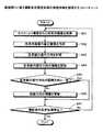
まず、実施例1に係る文字情報認識システムの概念について説明する。図1は、実施例1に係る文字情報認識システムの概念を説明する概念図である。図1に示すように、この文字情報認識システムは、カメラ10a〜10cと認識装置12a〜12cとがNTSC信号線11a〜11cを介して接続され、認識装置12a〜12cと回線集約装置14とが専用回線13a〜13cを介して接続され、回線集約装置14とサーバ装置17とが、ルータ15およびローカルエリアネットワーク16を介して接続され、サーバ装置17と端末装置18a〜18cとがローカルエリアネットワーク16を介して接続されている。 First, the concept of the character information recognition system according to the first embodiment will be described. FIG. 1 is a conceptual diagram illustrating the concept of the character information recognition system according to the first embodiment. As shown in FIG. 1, in this character information recognition system,
カメラ10a〜10cは、車両の画像を撮影する装置である。認識装置12a〜12cは、撮像装置10a〜10cにより撮影された車両の画像からナンバープレートに記された登録情報の情報を文字認識処理を実行することにより読み取る装置である。 The
さらに、認識装置12a〜12cは、各車線の車両の進行方向の情報を進行方向データ123bとして記憶し、撮影条件設定部124dが、記憶された進行方向データ123bに基づいて、ナンバープレートに記された登録情報の撮影に適切な撮影条件を設定する処理をおこなう。カメラ10a〜10cは、設定された撮影条件に基づいて、ナンバープレートに記された登録情報の撮影を実行する。 Further, the recognizing
認識装置12a〜12cにより文字認識された登録情報は、車両が撮影された場所や時刻などの情報とともに回線集約装置14に集められ、ルータ15およびローカルエリアネットワーク16を介してサーバ装置17に送信される。 The registration information recognized by the
サーバ装置17は、認識装置12a〜12cにより送信された車両の登録情報を、車両が撮影された場所や時刻などの情報とともにデータベースに蓄積する。そして、このサーバ装置17は、端末装置18a〜18cを操作する利用者から検索をおこなう車両の登録番号の情報を受け付けた際に、データベースから検索された車両の位置や時刻などの情報を端末装置18a〜18cに出力する。 The
このように、この文字情報認識システムにおいては、車両の進行方向が変化する場合に、認識装置12a〜12cが車両の進行方向の情報を記憶し、記憶した進行方向の情報に基づいて車両のナンバープレートに記された登録情報の撮影条件を設定することとしたので、車両のナンバープレートに記された登録情報の撮影条件を適切に設定することができる。 Thus, in this character information recognition system, when the traveling direction of the vehicle changes, the
図2は、図1に示したカメラ10a〜10cおよび認識装置12a〜12cの設置状況を示す図である。図2に示すように、この文字情報認識システムでは、信号機を支えるポール20にカメラ10a〜10cが設置され、また、ポール20わきには、撮影した車両のナンバープレートの画像に対して文字認識処理を実行する認識装置12a〜12cが設置される。 FIG. 2 is a diagram illustrating an installation state of the
ここで、カメラ10a〜10cは高解像度カメラであって、1台のカメラ10a〜10cで複数の車線21a,21bを撮影することが可能である。これにより、カメラ10a〜10cの台数を減らしてコストダウンを図るとともに、カメラ10a〜10cを目立たなくするようにしている。 Here, the
つぎに、図1に示した認識装置12aの機能的構成について説明する。図3は、図1に示した認識装置12aの機能的構成を示す機能ブロック図である。なお、図1に示した各認識装置12a〜12cは、同様の機能を有するので、ここでは認識装置12aを取り上げて説明する。図3に示すように、この認識装置12a〜12cは、インターフェース部120、入力部121、表示部122、記憶部123および制御部124を有する。 Next, the functional configuration of the
インターフェース部120は、カメラ10aとの間でNTSC信号線11aを介してデータの授受をおこない、また、回線集約装置14との間で専用回線13aを介してデータの授受をおこなうネットワークインターフェースである。入力部121は、キーボードやマウスなどの入力デバイスであり、表示部122は、ディスプレイなどの表示デバイスである。 The
記憶部123は、ハードディスク装置やメモリなどの記憶デバイスであり、制御部124との間でデータの授受をおこなう。この記憶部123は、画像データ123a、進行方向データ123bおよび撮影条件データ123cを記憶している。 The
画像データ123aは、カメラ10aにより時系列で撮影された画像のデータである。進行方向データ123bは、画像データ123aの解析により判定された車両の進行方向のデータである。 The
図4は、図3に示した進行方向データ123bの一例を示す図である。図4に示すように、この進行方向データ123bは、車線番号および進行方向のデータを有する。車線番号は、各車線に割り当てられた車線の識別番号である。進行方向は、車両の進行方向を番号で表したものである。たとえば、進行方向「0」は、車両の進行方向が道路の上り方向である場合を意味し、進行方向「1」は、車両の進行方向が道路の下り方向である場合を意味する。 FIG. 4 is a diagram illustrating an example of the traveling
撮影条件データ123cは、カメラ10aが車両のナンバープレートの画像を撮影する条件を設定したデータである。図5は、図3に示した撮影条件データ123cの一例を示す図である。 The
図5に示すように、この撮影条件データ123cは、車線番号および認識方向のデータを有する。車線番号は、各車線に割り当てられた車線の識別番号である。認識方向は、カメラ10aが車両のナンバープレートを撮影する際に参照されるデータであり、現在認識されている車両の進行方向を示すデータである。図5の例では、認識方向「0」は、車両の進行方向が道路の上り方向である場合を意味し、進行方向「1」は、車両の進行方向が道路の下り方向である場合を意味する。 As shown in FIG. 5, the photographing
前述したように、ナンバープレートを撮影する場合は、車両前部に取り付けられたナンバープレートを撮影するのか、車両後部に取り付けられたナンバープレートを撮影するのかにより、撮影のタイミングが異なるため、認識方向のデータに基づいて撮影のタイミングが調整される。 As mentioned above, when shooting a license plate, the timing of shooting differs depending on whether you are shooting a license plate attached to the front of the vehicle or a license plate attached to the rear of the vehicle. The shooting timing is adjusted based on the data.
制御部124は、認識装置12aを全体制御する制御部であり、撮影処理実行部124a、進行方向検出部124b、文字認識処理実行部124cおよび撮影条件設定部124dを有する。 The
撮影処理実行部124aは、カメラ10aにより撮影された時系列の画像を取得して、画像データ123aとして記憶する処理をおこなう。また、撮影処理実行部124aは、撮影条件データ123cを参照し、車両の進行方向に応じて所定のタイミングで車両のナンバープレートを撮影するようカメラ10aを制御する。 The photographing process execution unit 124a performs processing for acquiring time-series images photographed by the
すなわち、撮影処理実行部124aは、撮影条件データ123cを参照して、車両前部のナンバープレートを撮影するのか、あるいは、車両後部のナンバープレートを撮影するのかを判定し、最適なタイミングでナンバープレートを撮影するようカメラ10aに指示を出す。この撮影のタイミングについては、図7および図8において詳しく説明する。 That is, the imaging processing execution unit 124a refers to the
進行方向検出部124bは、画像データ123aに含まれる車両の時系列の画像を解析することにより、各車線を通行する車両の進行方向を検出する。具体的には、進行方向検出部124bは、時系列画像の差分画像(時刻tに撮影された画像と時刻t−1に撮影された画像との差分画像)を生成することにより、各車線の車両の進行方向を検出する。この処理については、図6でさらに詳しく説明する。また、進行方向検出部124bは、検出された車両の進行方向の情報を進行方向データ123bに記憶する処理をおこなう。 The traveling
文字認識処理実行部124cは、進行方向検出部124bにより生成された差分画像を重畳した重畳画像を作成し、作成した重畳画像に基づいて各車線の画像領域を車線数分設定する。この処理については、図6で詳しく説明する。 The character recognition
文字認識実行時には、文字認識処理実行部124cは、設定された画像領域ごとに車両のナンバープレートの画像を検出し、ナンバープレートに記された登録情報に対する文字認識処理を実行する。その後、文字認識処理実行部124cは、文字認識処理の結果得られた車両の登録情報を、撮影場所や撮影時刻などの情報とともに回線集約装置14に送信する。 At the time of executing character recognition, the character recognition
撮影条件設定部124dは、進行方向検出部124bにより登録された進行方向データ123bに基づいて、カメラ10aによる車両の撮影条件を設定する処理をおこなう。具体的には、撮影条件設定部124dは、進行方向データ123bを参照して各車線の車両の進行方向の情報を取得し、それらの情報が撮影条件データ123cに登録されている認識方向と一致するか否かを調べる。 The shooting
そして、撮影条件設定部124dは、進行方向データ123bに登録されている進行方向のデータと、撮影条件データ123cに登録されている認識方向のデータとが一致しない場合には、進行方向データ123bに登録されている進行方向のデータで撮影条件データ123cに登録されている認識方向のデータを更新する処理をおこなう。 Then, when the traveling direction data registered in the traveling
つぎに、認識装置12a〜12cがおこなう各車線の画像領域設定処理について説明する。図6は、認識装置12a〜12cがおこなう各車線の画像領域設定処理を説明する説明図である。図6に示すように、認識装置12a〜12cの進行方向判定部124bは、画像データ123aから車両の時系列画像60および61を取得する。ここで、時系列画像60は、時刻t−1に撮影された画像であり、時系列画像61は、時刻tに撮影された画像である。 Next, an image area setting process for each lane performed by the
そして、進行方向判定部124bは、時系列画像60と時系列画像61との差分画像62aを生成し、車両ごとの移動範囲63a,63bを検出する。同様にして、進行方向判定部124bは、時系列画像の組から差分画像62b〜62dを生成することにより、車両ごとの移動範囲の情報を抽出し、車線ごとの車両の進行方向の情報を取得する。 And the advancing
その後、文字認識処理実行部124cは、差分画像62a〜62dを重ね合わせて重畳画像64を作成する。重畳画像64においては、車両の移動範囲63a,63bが重なることにより、各車線に対応する画像領域65a,65bが生成される。これにより、文字認識処理実行部124cは、車両を検出する画像領域65a,65bを車線ごとに設定することができる。 Thereafter, the character recognition
つぎに、認識装置12a〜12cがおこなう車両検知処理について説明する。図7および図8は、認識装置12a〜12cがおこなう車両検知処理を説明する説明図(1)および(2)である。 Next, a vehicle detection process performed by the
図7は、車両71がカメラ10aの前方から接近してくる場合を示している。この場合、認識装置12a〜12cの撮影処理実行部124aは、時系列画像から生成された差分画像から、車両が接近してくることを検知する。 FIG. 7 shows a case where the
画像70aに示されている境界線72は、車両71の前部に取り付けられたナンバープレートの撮影をおこなうのに最も適した車両71の前部の位置を示すものである。この境界線72は、たとえば、カメラ10aの撮影領域の最下部から3分の1付近の位置に設定される。 The
そして、車両71の前部がこの境界線72に達した場合、すなわち、時系列画像70bに示されるような状態になった場合に、車両の撮影がおこなわれる。ここで、車両71の前部が境界線72に達したか否かは、車両71の画像のエッジを抽出し、車両71の前部に対応するエッジ部分が境界線72に達したか否かを判定することにより調べる。 When the front portion of the
また、撮影処理実行部124aは、人や自転車などの車両以外の移動体を誤って検出することを防ぐため、抽出されたエッジにより囲まれる面積やエッジの幅が、一定値以上のものだけを車両検出の対象とする。 In addition, in order to prevent erroneous detection of a moving body other than a vehicle such as a person or a bicycle, the imaging processing execution unit 124a only detects an area surrounded by the extracted edge and a width of the edge that is greater than a certain value. The target of vehicle detection.
図8は、車両81がカメラ10aの後方から走行してくる場合を示している。この場合も同様に、認識装置12a〜12cの撮影処理実行部124aは、時系列画像から生成された差分画像から、車両が進入してくることを検知する。 FIG. 8 shows a case where the
画像80aに示されている境界線82は、車両81の後部に取り付けられたナンバープレートの撮影をおこなうのに最も適した車両81の後部の位置を示すものである。そして、車両81の後部がこの境界線82に達した場合、すなわち、時系列画像80bに示されるような状態になった場合に、車両の撮影がおこなわれる。 The
この場合も、図7で説明したのと同様に、車両81の後部が境界線82に達したか否かは、車両81の画像のエッジを抽出し、車両81の後部に対応するエッジ部分が境界線82に達したか否かを判定することにより調べる。 Also in this case, as described with reference to FIG. 7, whether or not the rear portion of the
また、撮影処理実行部124aは、人や自転車などの車両以外の移動体を誤って検出することを防ぐため、抽出されたエッジにより囲まれる面積やエッジの幅が、一定値以上のものだけを車両検出の対象とする。 In addition, in order to prevent erroneous detection of a moving body other than a vehicle such as a person or a bicycle, the imaging processing execution unit 124a only detects an area surrounded by the extracted edge and a width of the edge that is greater than a certain value. The target of vehicle detection.
図7および図8で説明したように、車両がカメラ10aの前方から接近してくるのか、あるいは、カメラ10aの後方から走行してくるのかにより、ナンバープレートを撮影するタイミングが異なるため、認識装置12a〜12cの撮影条件設定部124dは、車両の進行方向に応じて車両の撮影条件を変更してそれに対処している。 As described with reference to FIGS. 7 and 8, since the timing at which the license plate is photographed differs depending on whether the vehicle approaches from the front of the
つぎに、実施例1に係る撮影条件設定処理の処理手順について説明する。図9は、実施例1に係る撮影条件設定処理の処理手順を説明するフローチャートである。図9に示すように、まず、認識装置12aの進行方向判定部124bは、カメラ10aにより撮影された時系列画像を画像データ123aから取得する(ステップSA1)。 Next, a processing procedure of imaging condition setting processing according to the first embodiment will be described. FIG. 9 is a flowchart illustrating the processing procedure of the imaging condition setting process according to the first embodiment. As shown in FIG. 9, first, the traveling
その後、進行方向判定部124bは、取得した時系列画像の差分処理を実行して差分画像を作成し(ステップSA2)、各車線ごとの車両の進行方向を判定する(ステップSA3)。そして、進行方向判定部124bは、各車線の進行方向の情報を記憶部123に進行方向データ123bとして記憶する(ステップSA4)。 Thereafter, the traveling
続いて、撮影条件設定部124dは、進行方向データ123bとして記憶された各車線の進行方向の情報が、撮影条件データ123cに記憶されている認識方向の情報と一致しているか否かを調べ(ステップSA5)、一致している場合には(ステップSA5,Yes)、ステップSA7に移行する。 Subsequently, the imaging
各車線の進行方向の情報が認識方向の情報と一致しない場合には(ステップSA5,No)、撮影条件設定部124dは、撮影条件データ123cの認識方向の情報を更新する処理をおこなう(ステップSA6)。 If the information on the traveling direction of each lane does not match the information on the recognition direction (step SA5, No), the imaging
その後、進行方向検出部124bは、撮影条件設定処理の停止指示を受け付けたか否かを調べ(ステップSA7)、停止指示を受け付けていない場合には(ステップSA7,No)、ステップSA1に移行して、撮影条件設定処理を継続する。停止指示を受け付けた場合には(ステップSA7,Yes)、この撮影条件設定処理を終了する。 Thereafter, the traveling
なお、上記撮影条件設定処理と、ナンバープレートの画像に対する文字認識処理は、平行しておこなわれ、撮影条件設定処理により設定された撮影条件は、カメラ10aによる撮影の制御に即座に反映され、撮影条件に基づいて撮影された車両の画像が画像データ104aとして蓄積されるとともに、蓄積された画像に対して文字認識処理が実行される。 The shooting condition setting process and the character recognition process for the license plate image are performed in parallel, and the shooting condition set by the shooting condition setting process is immediately reflected in the shooting control by the
以上説明してきたように、本実施例1では、認識装置12aの記憶部123が、車両の進行方向の情報を受け付けて進行方向データ123bとして記憶し、撮影条件設定部124dが、進行方向データ123bに記憶された車両の進行方向の情報に基づいて、車両のナンバープレートの画像の撮影条件を設定することとしたので、車両の進行方向が変化する場合に、車両のナンバープレートの撮影条件を適切に設定することができる。 As described above, in the first embodiment, the
また、本実施例1では、認識装置12aの進行方向検出部124bが、車両の進行方向を検出し、記憶部123が、検出された車両の進行方向の情報を受け付けて進行方向データ123bとして記憶することとしたので、車両の進行方向が変化する場合に、車両の進行方向を検出して車両のナンバープレートの撮影条件を適切に設定することができる。 In the first embodiment, the traveling
ところで、上記実施例1では、車両の進行方向の情報を時系列で撮影した画像を解析することにより取得することとしたが、認識装置が車線ごとの進行方向の変更スケジュールをあらかじめ記憶しておき、その変更スケジュールを参照して車線ごとの進行方向を検出することとしてもよい。そこで、本実施例2では、認識装置があらかじめ車線ごとの進行方向の変更スケジュールを記憶しておく場合について説明することとする。 By the way, in the first embodiment, information on the traveling direction of the vehicle is acquired by analyzing an image captured in time series. However, the recognition device stores in advance a schedule for changing the traveling direction for each lane. The traveling direction for each lane may be detected with reference to the change schedule. Therefore, in the second embodiment, a case will be described in which the recognition device stores a travel direction change schedule for each lane in advance.
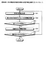
まず、本実施例2に係る認識装置100の機能的構成について説明する。図10は、実施例2に係る認識装置100の機能的構成を示す機能ブロック図である。ここで、図3に示した認識装置12aと同等の機能を有する機能部については、詳細な説明を省略する。図10に示すように、この認識装置100は、インターフェース部101、入力部102、表示部103、記憶部104および制御部105を有する。 First, a functional configuration of the
インターフェース部101は、カメラ10aとの間でNTSC信号線11aを介してデータの授受をおこない、また、回線集約装置14との間で専用回線13aを介してデータの授受をおこなうネットワークインターフェースである。入力部102は、キーボードやマウスなどの入力デバイスであり、表示部103は、ディスプレイなどの表示デバイスである。 The
記憶部104は、ハードディスク装置やメモリなどの記憶デバイスであり、制御部105との間でデータの授受をおこなう。この記憶部104は、画像データ104a、変更スケジュールデータ104bおよび撮影条件データ104cを記憶している。 The
画像データ104aは、カメラ10aにより時系列で撮影された画像のデータである。変更スケジュールデータ104bは、車線ごとの進行方向の変更スケジュールを記憶したデータである。 The
図11は、図10に示した変更スケジュールデータ104bの一例を示す図である。図11に示すように、この変更スケジュールデータ104bは、車線番号、時間帯および進行方向のデータを記憶している。 FIG. 11 is a diagram illustrating an example of the
車線番号は、各車線に割り当てられた車線の識別番号である。時間帯は、各車線に進行方向が設定される時間帯である。進行方向は、車線ごと、時間帯ごとに設定される車線の進行方向である。たとえば、進行方向「0」は、車両の進行方向が道路の上り方向である場合を意味し、進行方向「1」は、車両の進行方向が道路の下り方向である場合を意味する。図11の例では、車線「2」の進行方向が、10時に「1」から「0」に変更になる。 The lane number is a lane identification number assigned to each lane. The time zone is a time zone in which the traveling direction is set for each lane. The traveling direction is the traveling direction of the lane set for each lane and each time zone. For example, the traveling direction “0” means the case where the traveling direction of the vehicle is the upward direction of the road, and the traveling direction “1” means the case where the traveling direction of the vehicle is the downward direction of the road. In the example of FIG. 11, the traveling direction of the lane “2” is changed from “1” to “0” at 10:00.
図10の説明に戻ると、撮影条件データ104cは、カメラ10aが車両のナンバープレートの画像を撮影する条件を設定したデータであり、図5に示した撮影条件データ124cと同様のデータである。 Returning to the description of FIG. 10, the
制御部105は、認識装置100を全体制御する制御部であり、撮影処理実行部105a、変更スケジュール受付部105b、文字認識処理実行部105cおよび撮影条件設定部105dを有する。 The
撮影処理実行部105aは、カメラ10aにより撮影された時系列の画像を取得して、画像データ104aとして記憶する処理をおこなう。また、撮影処理実行部105aは、撮影条件データ104cを参照し、車両の進行方向に応じて所定のタイミングで車両のナンバープレートを撮影するようカメラ10aを制御する。 The imaging process execution unit 105a performs processing for acquiring time-series images captured by the
変更スケジュール受付部105bは、入力部102に入力された各車線を進行する車両の進行方向の変更スケジュールに係る情報を受け付けて、変更スケジュールデータ104bとして記憶する受付部である。あるいは、変更スケジュール受付部105bは、変更スケジュールを管理する装置(図示せず)から、ネットワークを介して送信された変更スケジュールの情報を受け付けることとしてもよい。 The change
文字認識処理実行部105cは、画像データ104aに含まれる車両の時系列の画像を解析することにより、図6の画像領域65a,65bに示したような、各車線に対応する画像領域を検出する。 The character recognition
具体的には、文字認識処理実行部105cは、時系列画像の差分画像(時刻tに撮影された画像と時刻t−1に撮影された画像との差分画像)を生成する。そして、文字認識処理実行部105cは、生成された差分画像を重畳した重畳画像を作成し、作成した重畳画像に基づいて各車線の画像領域を車線数分設定する。 Specifically, the character recognition
文字認識実行時には、文字認識処理実行部105cは、設定された画像領域ごとに車両のナンバープレートの画像を検出し、ナンバープレートに記された登録情報に対する文字認識処理を実行する。その後、文字認識処理実行部105cは、文字認識処理の結果得られた車両の登録情報を、撮影場所や撮影時刻などの情報とともに回線集約装置14に送信する。 When executing character recognition, the character recognition
撮影条件設定部105dは、変更スケジュールデータ104bに記憶された各車線の進行方向の変更スケジュールの情報に基づいて、カメラ10aによる車両の撮影条件を設定する処理をおこなう。 The shooting
具体的には、撮影条件設定部105dは、現在時刻の情報を時計(図示せず)から取得して、現在時刻が変更スケジュールデータ104bに記憶された時間帯のいずれに含まれるのかを判定する。そして、撮影条件設定部105dは、現在時刻が含まれる時間帯に対応する進行方向のデータを取得し、取得した進行方向のデータが撮影条件データ104cに登録されている認識方向のデータと一致するか否かを調べる。 Specifically, the imaging
その後、撮影条件設定部105dは、取得した進行方向のデータと撮影条件データ104cに登録されている認識方向のデータとが一致しない場合に、取得した進行方向の情報で撮影条件データ104cに登録されている認識方向の情報を更新する処理をおこなう。 Thereafter, when the acquired traveling direction data and the recognition direction data registered in the
つぎに、本実施例2に係る撮影条件設定処理の処理手順について説明する。図12は、実施例2に係る撮影条件設定処理の処理手順を説明するフローチャートである。ここでは、あらかじめ変更スケジュールデータ104bが記憶部104に記憶されているものとする。 Next, a processing procedure of imaging condition setting processing according to the second embodiment will be described. FIG. 12 is a flowchart for describing the processing procedure of the imaging condition setting processing according to the second embodiment. Here, it is assumed that the
図12に示すように、まず、認識装置100の撮影条件設定部105dは、時計から時刻の情報を取得する(ステップSB1)。続いて、撮影条件設定部105dは、変更スケジュールデータ104bから、各車線の進行方向の変更スケジュールの情報を取得する(ステップSB2)。 As shown in FIG. 12, first, the imaging
そして、撮影条件設定部105dは、変更スケジュールの情報と時刻の情報とを基にして進行方向の変更があったか否かを調べ(ステップSB3)、進行方向の変更がなかった場合には(ステップSB3,No)、ステップSB5に移行する。 Then, the imaging
進行方向の変更があった場合には(ステップSB3,Yes)、撮影条件設定部105dは、撮影条件データ104cの認識方向の情報を更新する処理をおこなう(ステップSB4)。 When there is a change in the traveling direction (step SB3, Yes), the imaging
その後、撮影条件設定部105dは、撮影条件設定処理の停止指示を受け付けたか否かを調べ(ステップSB5)、停止指示を受け付けていない場合には(ステップSB5,No)、ステップSB1に移行して、撮影条件設定処理を継続する。停止指示を受け付けた場合には(ステップSB5,Yes)、この撮影条件設定処理を終了する。 Thereafter, the shooting
上述してきたように、本実施例2では、認識装置100の記憶部104が、車両の進行方向の変更スケジュールに係る情報を受け付けて、受け付けた車両の進行方向の変更スケジュールに係る情報を変更スケジュールデータ104bに記憶し、撮影条件設定部105dが、変更スケジュールデータ104bに記憶された車両の進行方向の変更スケジュールに係る情報に基づいて、車両のナンバープレートの画像の撮影条件を設定することとしたので、変更スケジュールに基づいて車両の進行方向を効率的に検出し、車両のナンバープレートの撮影条件を適切に設定することができる。 As described above, in the second embodiment, the
以上本発明にかかる実施例について図面を参照して詳述してきたが、具体的な構成例はこれらの実施例に限られるものではなく、本発明の要旨を逸脱しない範囲の設計変更等があっても本発明に含まれる。 Although the embodiments according to the present invention have been described in detail with reference to the drawings, specific configuration examples are not limited to these embodiments, and there are design changes and the like within a scope not departing from the gist of the present invention. Is included in the present invention.
例えば、本実施例においては、文字情報認識システムの各機能を実現するためのプログラムをコンピュータ読み取り可能な記録媒体に記録して、この記録媒体に記録されたプログラムをコンピュータに読み込ませ、実行することにより各機能を実現してもよい。 For example, in this embodiment, a program for realizing each function of the character information recognition system is recorded on a computer-readable recording medium, and the program recorded on the recording medium is read by the computer and executed. Each function may be realized by the above.
図13は、文字情報認識システムの各機能を実現するコンピュータ200のハードウェア構成を示すブロック図である。図13に示すように、このコンピュータ200は、上記プログラムを実行するCPU210と、キーボード、マウス等の入力装置220と、各種データを記憶するROM230と、演算パラメータ等を記憶するRAM240と、文字情報認識システムの機能を実現するためのプログラムを記録した記録媒体300からプログラムを読み取る読取装置250と、ディスプレイ、プリンタ等の出力装置260と、ネットワーク400を介して他のコンピュータとの間でデータの授受をおこなうネットワークインターフェース270とが、バス280で接続された構成となっている。 FIG. 13 is a block diagram showing a hardware configuration of a
CPU210は、読取装置250を経由して記録媒体300に記録されているプログラムを読み込んだ後、プログラムを実行することにより、前述した機能を実現する。なお、記録媒体300としては、光ディスク、フレキシブルディスク、CD−ROM、ハードディスク等が挙げられる。また、このプログラムは、ネットワーク400を介してコンピュータ200に導入することとしてもよい。 The
また、本実施例においては、車両の進行方向が変更される2車線の道路にカメラを一台設置して、各車線を走行する車両の登録番号を読み取ることとしたが、本発明はこれに限定されるものではなく、車線の数は、1車線でもよいし、3車線以上でもよい。 Further, in this embodiment, one camera is installed on a two-lane road where the traveling direction of the vehicle is changed, and the registration number of the vehicle traveling in each lane is read. It is not limited, and the number of lanes may be one lane or three or more lanes.
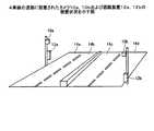
図14は、4車線の道路に設置されたカメラ10a,10bおよび認識装置12a,12bの設置状況を示す図である。図14に示すように、この例では、2車線14a,14b分の車両の登録番号の読み取り処理をカメラ10aおよび認識装置12aが実行し、2車線14c,14d分の車両の登録番号の読み取り処理をカメラ10bおよび認識装置12bが実行する。 FIG. 14 is a diagram illustrating the installation status of the
また、本実施例においては、文字情報認識システムが、自動車などの車両のナンバープレートに記された登録情報の読み取り処理をおこなうこととしたが、本発明はこれに限定されるものではなく、列車の車体に記された列車番号など、自動車以外の移動体の情報を読み取る処理を実行することとしてもよい。 In the present embodiment, the character information recognition system performs the reading process of the registered information written on the license plate of the vehicle such as an automobile. However, the present invention is not limited to this, and the train is not limited to this. It is good also as performing the process which reads the information of moving bodies other than a motor vehicle, such as the train number described on the vehicle body.
また、本実施例において説明した各処理のうち、自動的におこなわれるものとして説明した処理の全部または一部を手動的におこなうこともでき、あるいは、手動的におこなわれるものとして説明した処理の全部または一部を公知の方法で自動的におこなうこともできる。この他、上記データ中や図面中で示した処理手順、制御手順、具体的名称、各種のデータやパラメータを含む情報については、特記する場合を除いて任意に変更することができる。 In addition, among the processes described in this embodiment, all or part of the processes described as being performed automatically can be performed manually, or the processes described as being performed manually can be performed. All or a part can be automatically performed by a known method. In addition, the processing procedures, control procedures, specific names, and information including various data and parameters shown in the data and drawings can be arbitrarily changed unless otherwise specified.
また、図示した各装置の各構成要素は機能概念的なものであり、必ずしも物理的に図示の如く構成されていることを要しない。すなわち、各装置の分散・統合の具体的形態は図示のものに限られず、その全部または一部を、各種の負荷や使用状況などに応じて、任意の単位で機能的または物理的に分散・統合して構成することができる。 Further, each component of each illustrated apparatus is functionally conceptual, and does not necessarily need to be physically configured as illustrated. In other words, the specific form of distribution / integration of each device is not limited to that shown in the figure, and all or a part thereof may be functionally or physically distributed or arbitrarily distributed in arbitrary units according to various loads or usage conditions. Can be integrated and configured.
さらに、各装置にて行なわれる各処理機能は、その全部または任意の一部が、CPUおよび当該CPUにて解析実行されるプログラムにて実現され、あるいは、ワイヤードロジックによるハードウェアとして実現され得る。 Further, all or any part of each processing function performed in each device may be realized by a CPU and a program analyzed and executed by the CPU, or may be realized as hardware by wired logic.
(付記1)移動体を識別する識別情報に係る画像の撮影条件を設定する撮影条件設定プログラムであって、
前記移動体の進行方向に係る情報を受け付けて、受け付けた前記移動体の進行方向に係る情報を記憶する進行方向記憶手順と、
前記進行方向記憶手順により記憶された移動体の進行方向に係る情報に基づいて前記移動体を識別する識別情報に係る画像の撮影条件を設定する撮影条件設定手順と、
をコンピュータに実行させることを特徴とする撮影条件設定プログラム。(Supplementary Note 1) A shooting condition setting program for setting shooting conditions of an image related to identification information for identifying a moving body,
A traveling direction storage procedure for receiving information related to the traveling direction of the moving body and storing the received information regarding the traveling direction of the moving body;
A shooting condition setting procedure for setting a shooting condition of an image related to identification information for identifying the moving object based on information related to the moving direction of the moving object stored by the moving direction storing procedure;
An imaging condition setting program for causing a computer to execute.
(付記2)前記移動体の進行方向を検出する進行方向検出手順をさらに含み、前記進行方向記憶手順は、前記進行方向検出手順により検出された前記移動体の進行方向に係る情報を受け付けて記憶することを特徴とする付記1に記載の撮影条件設定プログラム。(Additional remark 2) It further includes the advancing direction detection procedure which detects the advancing direction of the said mobile body, The said advancing direction storage procedure receives and memorize | stores the information regarding the advancing direction of the said mobile body detected by the said advancing direction detection procedure. The imaging condition setting program according to
(付記3)前記進行方向記憶手順は、移動体の進行方向の変更スケジュールに係る情報を受け付けて、受け付けた前記移動体の進行方向の変更スケジュールに係る情報を記憶することを特徴とする付記1に記載の撮影条件設定プログラム。(Additional remark 3) The said advancing direction memory | storage procedure receives the information which concerns on the change schedule of the advancing direction of a moving body, and memorize | stores the information which concerns on the received advancing direction change schedule of the said moving body. Shooting condition setting program described in 1.
(付記4)移動体を識別する識別情報に係る画像の撮影条件を設定する撮影条件設定方法であって、
前記移動体の進行方向に係る情報を受け付けて、受け付けた前記移動体の進行方向に係る情報を記憶する進行方向記憶工程と、
前記進行方向記憶工程により記憶された移動体の進行方向に係る情報に基づいて前記移動体を識別する識別情報に係る画像の撮影条件を設定する撮影条件設定工程と、
を含んだことを特徴とする撮影条件設定方法。(Appendix 4) A shooting condition setting method for setting shooting conditions of an image related to identification information for identifying a moving body,
A traveling direction storing step of receiving information related to the traveling direction of the moving body and storing the received information related to the traveling direction of the moving body;
A shooting condition setting step of setting a shooting condition of an image related to identification information for identifying the moving body based on information related to the moving direction of the moving body stored by the moving direction storage step;
A shooting condition setting method characterized by comprising:
(付記5)前記移動体の進行方向を検出する進行方向検出工程をさらに含み、前記進行方向記憶工程は、前記進行方向検出工程により検出された前記移動体の進行方向に係る情報を受け付けて記憶することを特徴とする付記4に記載の撮影条件設定方法。(Additional remark 5) It further includes the advancing direction detection process which detects the advancing direction of the said mobile body, and the said advancing direction storage process receives and memorize | stores the information regarding the advancing direction of the said mobile body detected by the said advancing direction detection process. The imaging condition setting method according to appendix 4, wherein:
(付記6)前記進行方向記憶工程は、移動体の進行方向の変更スケジュールに係る情報を受け付けて、受け付けた前記移動体の進行方向の変更スケジュールに係る情報を記憶することを特徴とする付記4に記載の撮影条件設定方法。(Additional remark 6) The said advancing direction memory | storage process receives the information which concerns on the change schedule of the advancing direction of a moving body, and memorize | stores the information which concerns on the received advancing direction change schedule of the said moving body. The shooting condition setting method described in 1.
(付記7)移動体を識別する識別情報に係る画像の撮影条件を設定する撮影条件設定装置であって、
前記移動体の進行方向に係る情報を受け付けて、受け付けた前記移動体の進行方向に係る情報を記憶する進行方向記憶手段と、
前記進行方向記憶手段により記憶された移動体の進行方向に係る情報に基づいて前記移動体を識別する識別情報に係る画像の撮影条件を設定する撮影条件設定手段と、
を備えたことを特徴とする撮影条件設定装置。(Supplementary note 7) A photographing condition setting device for setting photographing conditions of an image related to identification information for identifying a moving body,
A traveling direction storage means for receiving information related to the traveling direction of the moving body and storing the received information regarding the traveling direction of the moving body;
Shooting condition setting means for setting shooting conditions of an image related to identification information for identifying the moving body based on information related to the traveling direction of the moving body stored by the traveling direction storage means;
An imaging condition setting device comprising:
(付記8)前記移動体の進行方向を検出する進行方向検出手段をさらに含み、前記進行方向記憶手段は、前記進行方向検出手段により検出された前記移動体の進行方向に係る情報を受け付けて記憶することを特徴とする付記7に記載の撮影条件設定装置。(Additional remark 8) It further includes the advancing direction detection means which detects the advancing direction of the said mobile body, The said advancing direction storage means receives and memorize | stores the information regarding the advancing direction of the said mobile body detected by the said advancing direction detection means. The imaging condition setting device according to appendix 7, wherein:
(付記9)前記進行方向記憶手段は、移動体の進行方向の変更スケジュールに係る情報を受け付けて、受け付けた前記移動体の進行方向の変更スケジュールに係る情報を記憶することを特徴とする付記7に記載の撮影条件設定装置。(Additional remark 9) The said advancing direction memory | storage means receives the information which concerns on the change schedule of the advancing direction of a moving body, and memorize | stores the information which concerns on the received advancing direction change schedule of the said moving body. The photographing condition setting device described in 1.
以上のように、本発明にかかる撮影条件設定プログラム、撮影条件設定方法および撮影条件設定装置は、車両などの移動体の進行方向が変化する場合に移動体を識別する識別情報の撮影条件を適切に設定することが必要とされる撮影条件設定システムや文字情報認識システムに有用である。 As described above, the imaging condition setting program, the imaging condition setting method, and the imaging condition setting device according to the present invention appropriately set the imaging condition of identification information for identifying a moving body when the traveling direction of the moving body such as a vehicle changes. This is useful for an imaging condition setting system and a character information recognition system that are required to be set to.
10a〜10c カメラ
11a〜11c NTSC信号線
12a〜12c,100 認識装置
101,120 インターフェース部
102,121 入力部
103,122 表示部
104,123 記憶部
104a,123a 画像データ
104b 変更スケジュールデータ
123b 進行方向データ
104c,123c 撮影条件データ
105,124 制御部
105a,124a 撮影処理実行部
105b 変更スケジュール受付部
105c,124c 文字認識処理実行部
105d,124d 撮影条件設定部
124b 進行方向検出部
13a〜13c 専用回線
14 回線集約装置
15 ルータ
16 ローカルエリアネットワーク
17 サーバ装置
18a〜18c 端末装置
60,61 時系列画像
62a〜62d 差分画像
63a,63b 車両移動範囲
64 重畳画像
65a,65b 車両認識領域10a to
Claims (7)
Translated fromJapanese前記移動体の車線ごとの進行方向に係る情報を受け付けて、受け付けた前記移動体の進行方向に係る情報を記憶する進行方向記憶手順と、
前記進行方向記憶手順により記憶された移動体の車線ごとの進行方向に係る情報に基づいて前記移動体を識別する識別情報に係る画像の撮影条件を車線ごとに設定する撮影条件設定手順と、
をコンピュータに実行させ、
前記コンピュータに接続されているカメラに対して、前記移動体の車線ごとの進行方向が第1の方向である場合には、前記移動体の進行方向前部が該カメラの撮影領域の第1の位置に達した際に該移動体の撮影を行う指示を行い、前記移動体の車線ごとの進行方向が第2の方向である場合には、前記移動体の進行方向後部が該カメラの前記撮影領域の第2の位置に達した際に該移動体の撮影を行う指示を行う文字認識手順をさらにコンピュータに実行させることを特徴とする撮影条件設定プログラム。A shooting condition setting program for setting shooting conditions of an image related to identification information for identifying a moving body,
A traveling direction storage procedure for receiving information related to the traveling direction of each lane of the moving body and storing the information related to the traveling direction of the received moving body;
A shooting condition setting procedure for setting, for each lane, a shooting condition of an image related to identification information for identifying the moving body based on information related to a traveling direction of each moving lane of the moving body stored by the traveling direction storage procedure;
To the computer,
When the moving direction of the moving body for each lane is the first direction with respect to the camera connected to the computer, the front of the moving direction of the moving body is the first shooting area of the camera. When the moving body is instructed to shoot the moving body and the moving direction of the moving body for each lane is the second direction, the moving direction rear part of the moving body is the shooting direction of the camera. An imaging condition setting programfor causing a computer to further execute a character recognition procedure for giving an instruction to perform imaging of the moving object when the second position of the area is reached .
前記コンピュータが、前記移動体の車線ごとの進行方向に係る情報を受け付けて、受け付けた前記移動体の進行方向に係る情報を記憶手段に記憶する進行方向記憶工程と、
前記コンピュータが、前記進行方向記憶工程により前記記憶手段に記憶された移動体の車線ごとの進行方向に係る情報に基づいて前記移動体を識別する識別情報に係る画像の撮影条件を、前記移動体の車線ごとの進行方向が第1の方向である場合には、前記移動体の進行方向前部が該カメラの撮影領域の第1の位置に達した際に該移動体の撮影が行われ、前記移動体の車線ごとの進行方向が第2の方向である場合には、前記移動体の進行方向後部が該カメラの前記撮影領域の第2の位置に達した際に該移動体の撮影が行われるように設定する撮影条件設定工程と、
を含んだことを特徴とする撮影条件設定方法。A shooting condition setting method in which a computer sets shooting conditions of an image related to identification information for identifying a moving body,
A traveling direction storage step in which the computer receives information related to the traveling direction of each lane of the moving body and stores the received information related to the traveling direction of the moving body in a storage unit;
The computer is configured to capture an imaging condition ofan image related to identification information for identifying the moving body based on information related to a traveling direction of each moving lane of the moving body stored in the storage unit by the traveling direction storing step.When the traveling direction of each lane is the first direction, the moving body is photographed when the front of the traveling direction of the moving body reaches the first position in the photographing region of the camera, When the traveling direction of the moving body for each lane is the second direction, the moving body is photographed when the rear part of the traveling direction of the moving body reaches the second position of the photographing region of the camera. A shooting condition setting stepfor setting tobe performed ;
A shooting condition setting method characterized by comprising:
前記移動体の車線ごとの進行方向に係る情報を受け付けて、受け付けた前記移動体の進行方向に係る情報を記憶する進行方向記憶手段と、
前記進行方向記憶手段により記憶された移動体の車線ごとの進行方向に係る情報に基づいて前記移動体を識別する識別情報に係る画像の撮影条件を、該画像を撮影するカメラに対して、前記移動体の車線ごとの進行方向が第1の方向である場合には、前記移動体の進行方向前部が該カメラの撮影領域の第1の位置に達した際に該移動体の撮影が行われ、前記移動体の車線ごとの進行方向が第2の方向である場合には、前記移動体の進行方向後部が該カメラの前記撮影領域の第2の位置に達した際に該移動体の撮影が行われるように設定する撮影条件設定手段と、
を備えたことを特徴とする撮影条件設定装置。A shooting condition setting device for setting shooting conditions of an image related to identification information for identifying a moving body,
A traveling direction storage means for receiving information related to the traveling direction of each lane of the moving body and storing the received information regarding the traveling direction of the moving body;
The imaging conditions for the image related to the identification information for identifying the moving body based on the information related to the traveling direction for each lane of the moving body stored by the traveling direction storage means, withrespect to the camera that captures the image, When the moving direction of the moving body for each lane is the first direction, shooting of the moving body is performed when the front portion of the moving body reaches the first position in the shooting area of the camera. In the case where the traveling direction of the moving body for each lane is the second direction, when the rear portion of the traveling direction of the moving body reaches the second position of the imaging region of the camera, Shooting condition setting meansfor setting to perform shooting,
An imaging condition setting device comprising:
Priority Applications (2)
| Application Number | Priority Date | Filing Date | Title |
|---|---|---|---|
| JP2004023164AJP4391839B2 (en) | 2004-01-30 | 2004-01-30 | Shooting condition setting program, shooting condition setting method, and shooting condition setting apparatus |
| US10/851,160US7630515B2 (en) | 2004-01-30 | 2004-05-24 | Method of and apparatus for setting image-capturing conditions, and computer program |
Applications Claiming Priority (1)
| Application Number | Priority Date | Filing Date | Title |
|---|---|---|---|
| JP2004023164AJP4391839B2 (en) | 2004-01-30 | 2004-01-30 | Shooting condition setting program, shooting condition setting method, and shooting condition setting apparatus |
Publications (2)
| Publication Number | Publication Date |
|---|---|
| JP2005216070A JP2005216070A (en) | 2005-08-11 |
| JP4391839B2true JP4391839B2 (en) | 2009-12-24 |
Family
ID=34805701
Family Applications (1)
| Application Number | Title | Priority Date | Filing Date |
|---|---|---|---|
| JP2004023164AExpired - Fee RelatedJP4391839B2 (en) | 2004-01-30 | 2004-01-30 | Shooting condition setting program, shooting condition setting method, and shooting condition setting apparatus |
Country Status (2)
| Country | Link |
|---|---|
| US (1) | US7630515B2 (en) |
| JP (1) | JP4391839B2 (en) |
Families Citing this family (44)
| Publication number | Priority date | Publication date | Assignee | Title |
|---|---|---|---|---|
| JP4739699B2 (en)* | 2004-06-30 | 2011-08-03 | 株式会社日立製作所 | License plate recognition apparatus and method |
| US8306272B2 (en)* | 2007-05-31 | 2012-11-06 | Microsemi Corporation | Method and system for dynamically altering the analysis methodology of millimeter wave imagery in response to the range and direction of motion of a subject |
| JP5258601B2 (en)* | 2009-01-29 | 2013-08-07 | 三菱電機株式会社 | License plate reader and license plate reading system |
| MX2010005149A (en)* | 2009-05-08 | 2012-10-11 | Security systems. | |
| CA2794728A1 (en) | 2010-06-16 | 2011-12-22 | Ndi Technologies, Inc. | Usb video interface for alpr cameras and associated method |
| JP2012038089A (en)* | 2010-08-06 | 2012-02-23 | Nikon Corp | Information management device, data analysis device, signal, server, information management system, and program |
| US20120033123A1 (en) | 2010-08-06 | 2012-02-09 | Nikon Corporation | Information control apparatus, data analyzing apparatus, signal, server, information control system, signal control apparatus, and program |
| US8908007B2 (en)* | 2011-07-15 | 2014-12-09 | Panasonic Corporation | Transmission device and transmission method |
| JP5924054B2 (en)* | 2012-03-19 | 2016-05-25 | 富士通株式会社 | Program, information processing apparatus and information processing method |
| JP2014016706A (en)* | 2012-07-06 | 2014-01-30 | Nissan Motor Co Ltd | Information acquisition system and information acquisition method |
| CN103679164A (en)* | 2012-09-21 | 2014-03-26 | 阿里巴巴集团控股有限公司 | A method and a system for identifying and processing a mark based on a mobile terminal |
| CN103021184B (en)* | 2012-12-26 | 2015-08-26 | 江苏大学 | Block auxiliary discriminating conduct and the system of car plate vehicle |
| CN103198315B (en)* | 2013-04-17 | 2015-12-02 | 南京理工大学 | Based on the Character Segmentation of License Plate of character outline and template matches |
| WO2015026834A1 (en) | 2013-08-19 | 2015-02-26 | Nant Holdings Ip, Llc | Camera-to-camera interactions, systems and methods |
| CN103646548A (en)* | 2013-12-06 | 2014-03-19 | 镇江市星禾物联科技有限公司 | Image identification technology-based license plate identification method |
| US10515285B2 (en) | 2014-06-27 | 2019-12-24 | Blinker, Inc. | Method and apparatus for blocking information from an image |
| US9818154B1 (en) | 2014-06-27 | 2017-11-14 | Blinker, Inc. | System and method for electronic processing of vehicle transactions based on image detection of vehicle license plate |
| US9594971B1 (en) | 2014-06-27 | 2017-03-14 | Blinker, Inc. | Method and apparatus for receiving listings of similar vehicles from an image |
| US10733471B1 (en) | 2014-06-27 | 2020-08-04 | Blinker, Inc. | Method and apparatus for receiving recall information from an image |
| US9779318B1 (en) | 2014-06-27 | 2017-10-03 | Blinker, Inc. | Method and apparatus for verifying vehicle ownership from an image |
| US9558419B1 (en) | 2014-06-27 | 2017-01-31 | Blinker, Inc. | Method and apparatus for receiving a location of a vehicle service center from an image |
| US10867327B1 (en) | 2014-06-27 | 2020-12-15 | Blinker, Inc. | System and method for electronic processing of vehicle transactions based on image detection of vehicle license plate |
| US9589202B1 (en) | 2014-06-27 | 2017-03-07 | Blinker, Inc. | Method and apparatus for receiving an insurance quote from an image |
| US9773184B1 (en) | 2014-06-27 | 2017-09-26 | Blinker, Inc. | Method and apparatus for receiving a broadcast radio service offer from an image |
| US10540564B2 (en) | 2014-06-27 | 2020-01-21 | Blinker, Inc. | Method and apparatus for identifying vehicle information from an image |
| US9589201B1 (en) | 2014-06-27 | 2017-03-07 | Blinker, Inc. | Method and apparatus for recovering a vehicle value from an image |
| US9754171B1 (en) | 2014-06-27 | 2017-09-05 | Blinker, Inc. | Method and apparatus for receiving vehicle information from an image and posting the vehicle information to a website |
| US9607236B1 (en) | 2014-06-27 | 2017-03-28 | Blinker, Inc. | Method and apparatus for providing loan verification from an image |
| US9760776B1 (en) | 2014-06-27 | 2017-09-12 | Blinker, Inc. | Method and apparatus for obtaining a vehicle history report from an image |
| US10572758B1 (en) | 2014-06-27 | 2020-02-25 | Blinker, Inc. | Method and apparatus for receiving a financing offer from an image |
| US9563814B1 (en) | 2014-06-27 | 2017-02-07 | Blinker, Inc. | Method and apparatus for recovering a vehicle identification number from an image |
| US9600733B1 (en) | 2014-06-27 | 2017-03-21 | Blinker, Inc. | Method and apparatus for receiving car parts data from an image |
| US9892337B1 (en) | 2014-06-27 | 2018-02-13 | Blinker, Inc. | Method and apparatus for receiving a refinancing offer from an image |
| US10579892B1 (en) | 2014-06-27 | 2020-03-03 | Blinker, Inc. | Method and apparatus for recovering license plate information from an image |
| US9990376B2 (en)* | 2015-06-23 | 2018-06-05 | Hunter Engineering Company | Methods for identifying a vehicle from captured image data |
| US10423839B2 (en)* | 2015-11-25 | 2019-09-24 | Laser Technology, Inc. | System for monitoring vehicular traffic |
| CN105447528B (en)* | 2015-12-29 | 2018-11-27 | 同方威视技术股份有限公司 | Train license number and model recognizing method and system and safety detection method and system |
| CN105702049A (en)* | 2016-03-29 | 2016-06-22 | 成都理工大学 | DSP-based emergency lane monitoring system and realizing method thereof |
| US11094191B2 (en)* | 2018-04-27 | 2021-08-17 | Iurii V. Iuzifovich | Distributed safety infrastructure for autonomous vehicles and methods of use |
| US11126863B2 (en)* | 2018-06-08 | 2021-09-21 | Southwest Airlines Co. | Detection system |
| JP7006527B2 (en)* | 2018-07-09 | 2022-01-24 | トヨタ自動車株式会社 | In-vehicle equipment and vehicle search system |
| CN109344829B (en)* | 2018-07-23 | 2021-05-18 | 广州科易光电技术有限公司 | Train number identification method and device for high-speed railway train |
| WO2020065973A1 (en)* | 2018-09-28 | 2020-04-02 | 日本電気株式会社 | Detection system, detection method and program |
| KR102763116B1 (en)* | 2019-07-05 | 2025-02-10 | 현대자동차주식회사 | Advanced Driver Assistance System, Vehicle having the same and method for controlling the vehicle |
Family Cites Families (19)
| Publication number | Priority date | Publication date | Assignee | Title |
|---|---|---|---|---|
| DE3532527A1 (en)* | 1985-09-12 | 1987-03-19 | Robot Foto Electr Kg | DEVICE FOR PHOTOGRAPHIC MONITORING OF CROSSINGS |
| JPH06187591A (en)* | 1992-12-15 | 1994-07-08 | Omron Corp | System for detecting vehicle travel violation |
| US5764786A (en)* | 1993-06-10 | 1998-06-09 | Kuwashima; Shigesumi | Moving object measurement device employing a three-dimensional analysis to obtain characteristics of the moving object |
| JP3388833B2 (en)* | 1993-10-19 | 2003-03-24 | 株式会社応用計測研究所 | Measuring device for moving objects |
| US5699056A (en)* | 1994-12-28 | 1997-12-16 | Omron Corporation | Traffic information system |
| US6079862A (en)* | 1996-02-22 | 2000-06-27 | Matsushita Electric Works, Ltd. | Automatic tracking lighting equipment, lighting controller and tracking apparatus |
| US6760061B1 (en)* | 1997-04-14 | 2004-07-06 | Nestor Traffic Systems, Inc. | Traffic sensor |
| AU761072C (en)* | 1998-11-23 | 2003-07-10 | Nestor, Inc. | Traffic light violation prediction and recording system |
| US6223125B1 (en) | 1999-02-05 | 2001-04-24 | Brett O. Hall | Collision avoidance system |
| JP3920535B2 (en)* | 2000-06-12 | 2007-05-30 | 株式会社日立製作所 | Vehicle detection method and vehicle detection device |
| JP3806293B2 (en)* | 2000-08-15 | 2006-08-09 | 三菱重工業株式会社 | Vehicle monitoring device |
| JP2003022494A (en) | 2001-07-10 | 2003-01-24 | Fujitsu Ltd | Mobile character recognition system |
| US6690294B1 (en)* | 2001-07-10 | 2004-02-10 | William E. Zierden | System and method for detecting and identifying traffic law violators and issuing citations |
| JP2003281689A (en)* | 2002-03-20 | 2003-10-03 | Mitsubishi Heavy Ind Ltd | Vehicle tracking sensor |
| JP3790817B2 (en)* | 2002-03-27 | 2006-06-28 | 国土交通省国土技術政策総合研究所長 | Chuo line shift processing equipment |
| US6958709B2 (en)* | 2002-08-08 | 2005-10-25 | General Electric Company | Method, system, and storage medium for integrating vehicle management, transportation and communications functions |
| JP3730208B2 (en)* | 2002-10-21 | 2005-12-21 | 株式会社リコー | Shutter control device for photographing apparatus |
| US20050033505A1 (en)* | 2002-12-05 | 2005-02-10 | Premier Wireless, Inc. | Traffic surveillance and report system |
| US6970102B2 (en)* | 2003-05-05 | 2005-11-29 | Transol Pty Ltd | Traffic violation detection, recording and evidence processing system |
- 2004
- 2004-01-30JPJP2004023164Apatent/JP4391839B2/ennot_activeExpired - Fee Related
- 2004-05-24USUS10/851,160patent/US7630515B2/ennot_activeExpired - Fee Related
Also Published As
| Publication number | Publication date |
|---|---|
| US7630515B2 (en) | 2009-12-08 |
| US20050169500A1 (en) | 2005-08-04 |
| JP2005216070A (en) | 2005-08-11 |
Similar Documents
| Publication | Publication Date | Title |
|---|---|---|
| JP4391839B2 (en) | Shooting condition setting program, shooting condition setting method, and shooting condition setting apparatus | |
| JP6109593B2 (en) | Risk information processing method, apparatus and system, and program | |
| CN101542554B (en) | Vehicle Obstacle Detection System and Method | |
| KR102491091B1 (en) | Method for producing collection video clip and, integrated unmanned traffic control system for two/four wheeled vehicle therewith | |
| KR101748552B1 (en) | Multidirection Photographing System for Roadway Monitor | |
| KR100906203B1 (en) | System for tracking the vehicles using GIS | |
| KR101804471B1 (en) | Method And Apparatus for Analyzing Video | |
| JP2006260483A (en) | Face matching system and face matching method | |
| JP2023134733A (en) | Information processing device | |
| KR101256873B1 (en) | A method for tracking object, an object tracking apparatus and a traffic watching system | |
| JP2009048225A (en) | Vehicle recognition apparatus and vehicle recognition method | |
| JP2010262527A (en) | Passer counting device, passer counting method, and passer counting program | |
| JPWO2020003764A1 (en) | Image processors, mobile devices, and methods, and programs | |
| KR101653385B1 (en) | System for cracking down on parking violation of automatic movable using tablet pc and method therefor | |
| JP7102383B2 (en) | Road surface image management system and its road surface image management method | |
| KR100869139B1 (en) | Vehicle license plate recognition system using image input signal to portable terminal and its recognition method | |
| JP2004258981A (en) | Vehicle monitoring method and device | |
| JP2021071780A (en) | Information processing device, information processing method, and program | |
| JP6665521B2 (en) | Information processing apparatus, information processing system, and information processing program | |
| KR20220107679A (en) | Edge computing device for tracking object, method for controlling the same, and server | |
| KR100485419B1 (en) | System For Acquiring Information On A Vehicle | |
| JP2005140754A (en) | Method of detecting person, monitoring system, and computer program | |
| KR101758291B1 (en) | Apparatus for recongniting object of vehicle of image recording system using vehicle and method thereof | |
| JP2020160728A (en) | Vehicle platoon support method, vehicle control device, and vehicle platoon support system | |
| JP7284867B2 (en) | Person tracking management server |
Legal Events
| Date | Code | Title | Description |
|---|---|---|---|
| A621 | Written request for application examination | Free format text:JAPANESE INTERMEDIATE CODE: A621 Effective date:20060509 | |
| A977 | Report on retrieval | Free format text:JAPANESE INTERMEDIATE CODE: A971007 Effective date:20090417 | |
| A131 | Notification of reasons for refusal | Free format text:JAPANESE INTERMEDIATE CODE: A131 Effective date:20090421 | |
| A521 | Request for written amendment filed | Free format text:JAPANESE INTERMEDIATE CODE: A523 Effective date:20090622 | |
| A131 | Notification of reasons for refusal | Free format text:JAPANESE INTERMEDIATE CODE: A131 Effective date:20090714 | |
| A521 | Request for written amendment filed | Free format text:JAPANESE INTERMEDIATE CODE: A523 Effective date:20090908 | |
| TRDD | Decision of grant or rejection written | ||
| A01 | Written decision to grant a patent or to grant a registration (utility model) | Free format text:JAPANESE INTERMEDIATE CODE: A01 Effective date:20091006 | |
| A01 | Written decision to grant a patent or to grant a registration (utility model) | Free format text:JAPANESE INTERMEDIATE CODE: A01 | |
| A61 | First payment of annual fees (during grant procedure) | Free format text:JAPANESE INTERMEDIATE CODE: A61 Effective date:20091008 | |
| FPAY | Renewal fee payment (event date is renewal date of database) | Free format text:PAYMENT UNTIL: 20121016 Year of fee payment:3 | |
| R150 | Certificate of patent or registration of utility model | Ref document number:4391839 Country of ref document:JP Free format text:JAPANESE INTERMEDIATE CODE: R150 Free format text:JAPANESE INTERMEDIATE CODE: R150 | |
| FPAY | Renewal fee payment (event date is renewal date of database) | Free format text:PAYMENT UNTIL: 20121016 Year of fee payment:3 | |
| FPAY | Renewal fee payment (event date is renewal date of database) | Free format text:PAYMENT UNTIL: 20131016 Year of fee payment:4 | |
| LAPS | Cancellation because of no payment of annual fees |