JP4391762B2 - Surgical instrument - Google Patents
Surgical instrumentDownload PDFInfo
- Publication number
- JP4391762B2 JP4391762B2JP2003130726AJP2003130726AJP4391762B2JP 4391762 B2JP4391762 B2JP 4391762B2JP 2003130726 AJP2003130726 AJP 2003130726AJP 2003130726 AJP2003130726 AJP 2003130726AJP 4391762 B2JP4391762 B2JP 4391762B2
- Authority
- JP
- Japan
- Prior art keywords
- treatment
- rotation
- knob
- base
- unit
- Prior art date
- Legal status (The legal status is an assumption and is not a legal conclusion. Google has not performed a legal analysis and makes no representation as to the accuracy of the status listed.)
- Expired - Fee Related
Links
- 238000011282treatmentMethods0.000claimsdescription337
- 238000001356surgical procedureMethods0.000claimsdescription87
- 238000003780insertionMethods0.000claimsdescription77
- 230000037431insertionEffects0.000claimsdescription77
- 230000033001locomotionEffects0.000claimsdescription27
- 206010048669Terminal stateDiseases0.000claimsdescription14
- 238000010977unit operationMethods0.000claimsdescription9
- 230000004044responseEffects0.000claimsdescription4
- 230000008878couplingEffects0.000claims3
- 238000010168coupling processMethods0.000claims3
- 238000005859coupling reactionMethods0.000claims3
- 238000010586diagramMethods0.000description40
- 230000007246mechanismEffects0.000description38
- 230000002093peripheral effectEffects0.000description20
- 210000000078clawAnatomy0.000description10
- 210000003811fingerAnatomy0.000description10
- 230000008859changeEffects0.000description7
- 238000005452bendingMethods0.000description6
- 230000009471actionEffects0.000description5
- 230000005540biological transmissionEffects0.000description4
- 239000011248coating agentSubstances0.000description2
- 238000000576coating methodMethods0.000description2
- 230000003247decreasing effectEffects0.000description2
- 238000002674endoscopic surgeryMethods0.000description2
- 238000012545processingMethods0.000description2
- 238000001467acupunctureMethods0.000description1
- 238000004140cleaningMethods0.000description1
- 238000004891communicationMethods0.000description1
- 230000009977dual effectEffects0.000description1
- 230000000694effectsEffects0.000description1
- 230000001771impaired effectEffects0.000description1
- 230000009545invasionEffects0.000description1
- 238000002350laparotomyMethods0.000description1
- 238000000034methodMethods0.000description1
- 238000012986modificationMethods0.000description1
- 230000004048modificationEffects0.000description1
- 229910001220stainless steelInorganic materials0.000description1
- 239000010935stainless steelSubstances0.000description1
- 210000003813thumbAnatomy0.000description1
- 210000000707wristAnatomy0.000description1
Images


Classifications
- A—HUMAN NECESSITIES
- A61—MEDICAL OR VETERINARY SCIENCE; HYGIENE
- A61B—DIAGNOSIS; SURGERY; IDENTIFICATION
- A61B17/00—Surgical instruments, devices or methods
- A61B17/28—Surgical forceps
- A61B17/29—Forceps for use in minimally invasive surgery
- A—HUMAN NECESSITIES
- A61—MEDICAL OR VETERINARY SCIENCE; HYGIENE
- A61B—DIAGNOSIS; SURGERY; IDENTIFICATION
- A61B17/00—Surgical instruments, devices or methods
- A61B17/34—Trocars; Puncturing needles
- A61B17/3462—Trocars; Puncturing needles with means for changing the diameter or the orientation of the entrance port of the cannula, e.g. for use with different-sized instruments, reduction ports, adapter seals
- A—HUMAN NECESSITIES
- A61—MEDICAL OR VETERINARY SCIENCE; HYGIENE
- A61B—DIAGNOSIS; SURGERY; IDENTIFICATION
- A61B17/00—Surgical instruments, devices or methods
- A61B17/34—Trocars; Puncturing needles
- A61B17/3498—Valves therefor, e.g. flapper valves, slide valves
- A—HUMAN NECESSITIES
- A61—MEDICAL OR VETERINARY SCIENCE; HYGIENE
- A61B—DIAGNOSIS; SURGERY; IDENTIFICATION
- A61B17/00—Surgical instruments, devices or methods
- A61B2017/0046—Surgical instruments, devices or methods with a releasable handle; with handle and operating part separable
- A—HUMAN NECESSITIES
- A61—MEDICAL OR VETERINARY SCIENCE; HYGIENE
- A61B—DIAGNOSIS; SURGERY; IDENTIFICATION
- A61B17/00—Surgical instruments, devices or methods
- A61B17/28—Surgical forceps
- A61B17/29—Forceps for use in minimally invasive surgery
- A61B2017/2901—Details of shaft
- A61B2017/2902—Details of shaft characterized by features of the actuating rod
- A—HUMAN NECESSITIES
- A61—MEDICAL OR VETERINARY SCIENCE; HYGIENE
- A61B—DIAGNOSIS; SURGERY; IDENTIFICATION
- A61B17/00—Surgical instruments, devices or methods
- A61B17/28—Surgical forceps
- A61B17/29—Forceps for use in minimally invasive surgery
- A61B2017/2926—Details of heads or jaws
- A61B2017/2927—Details of heads or jaws the angular position of the head being adjustable with respect to the shaft
- A61B2017/2929—Details of heads or jaws the angular position of the head being adjustable with respect to the shaft with a head rotatable about the longitudinal axis of the shaft
- A—HUMAN NECESSITIES
- A61—MEDICAL OR VETERINARY SCIENCE; HYGIENE
- A61B—DIAGNOSIS; SURGERY; IDENTIFICATION
- A61B17/00—Surgical instruments, devices or methods
- A61B17/28—Surgical forceps
- A61B17/29—Forceps for use in minimally invasive surgery
- A61B2017/2926—Details of heads or jaws
- A61B2017/2932—Transmission of forces to jaw members
- A61B2017/2939—Details of linkages or pivot points
Landscapes
- Health & Medical Sciences (AREA)
- Surgery (AREA)
- Life Sciences & Earth Sciences (AREA)
- Biomedical Technology (AREA)
- Nuclear Medicine, Radiotherapy & Molecular Imaging (AREA)
- Engineering & Computer Science (AREA)
- Ophthalmology & Optometry (AREA)
- Heart & Thoracic Surgery (AREA)
- Medical Informatics (AREA)
- Molecular Biology (AREA)
- Animal Behavior & Ethology (AREA)
- General Health & Medical Sciences (AREA)
- Public Health (AREA)
- Veterinary Medicine (AREA)
- Surgical Instruments (AREA)
Description
Translated fromJapanese【0001】
【発明の属する技術分野】
本発明は、術者が挿入部の基端部に設けられた操作部を把持した状態で、挿入部の先端部に設けられている外科的処置部を適宜操作して外科手術、特に内視鏡下外科手術を行う際に使用する外科用処置具に関する。
【0002】
【従来の技術】
従来より体腔内等へ細長に形成した挿入部を有する内視鏡を挿入して得られる被写体像を観察しながら、処置部位に対する観察や各種処置を行うことのできる内視鏡が広く用いられている。また、近年、患者への侵襲を小さくするために開腹することなく、観察用の内視鏡を体腔内に導くトラカールと外科用処置具を処置部位に導くトラカールとを穿刺して、内視鏡で外科用処置具と処置部位とを観察しながら治療、処置を行う内視鏡下外科手術等が行われている。
【0003】
内視鏡下外科手術等で使用される外科用処置具は、細長で、挿入部の先端部に配置されている外科的処置部(以下、処置部材ともいう)を挿入部の手元側に設けた操作部を操作して動作させるようになっている。
【0004】
そして、米国出願(以下、USPと略記する)5,374,277、USP5,549,637、USP5,350,391には先端側に配置されている処置部材を、外科用処置具の主軸に対して回動自在とし、かつ回動した状態では処置部材をその軸まわりに回転可能にしたもの等が示されている。
【0005】
具体的に、前記USP5,374,277の外科用処置具では、先端部を外科用処置具の主軸に対して回動可能にする回動関節を備え、この回動関節の先端側に処置部材のマウントを備えている。このマウントは手首手段によって、先端側の第1マウントと基端側の第2マウントとに分割された構成である。このことによって、第1マウントの先端部に備えられた処置部材が、回動関節より先端側の前記軸廻りに対して回転可能になっている。
【0006】
前記USP5,549,637の関節部を有する医療機器では、先端部が処置具の主軸に対して回動可能で、かつ回動関節の先端側の軸廻りに回転可能である。先端部の回動機構にはワイヤー又はケーブル等の柔軟な駆動手段が備えられている。そして、回動関節の先端側を軸廻りに回転させる機構として、操作部及び回動関節部等の各部に平歯車や傘歯車を使用する一方、先端に装着される処置部材を操作する機構にはリンク部品を介してプッシュロッド状の部材が備えられている。
【0007】
前記USP5,350,391の腹腔鏡機器は、先端に備えられた処置部材の回動操作を、一対の操作ハンドルの一方のハンドルで行い、また処置部材の開閉運動の操作を他方のハンドルにより行う形式である。
【0008】
【特許文献1】
USP5,374,277号
【0009】
【特許文献2】
USP5,549,637号
【0010】
【特許文献3】
USP5,350,391号
【0011】
【発明が解決しようとする課題】
しかしながら、前記USP5,374,277の外科用処置具では、回転操作自体を外科用処置具の基端側に設けられている操作部で遠隔操作し得る構成でなかった。このため、実使用状況において操作性に不具合が生じる。また、回転操作可能な角度も、予め決められた起点となる位置から45度若しくは90度といった離散的な回転角度を選択し得るにすぎず、操作性に乏しかった。さらに、処置部材の開閉機構にケーブル部材を採用していたため、実際の処置部材の開閉操作時に、ハンドル開閉操作との一体感(ダイレクト感)が欠け、特に、処置部材を開く操作が重要である生体組織の剥離操作において不都合が生じるおそれがあった。
【0012】
また、前記USP5,549,637の関節部を有する医療機器では、先端部の回動機構、先端部の軸まわり回転機構、処置部材の操作機構が各々固有の構造を必要としているため、全体の構成が非常に複雑である。また、歯車のバックラッシュ等により無感応域が発生することによって実際の操作性が損なわれるおそれがあった。さらに、回動操作をワイヤ、ケーブル等の柔軟性を有する部材によって行っていたため、回動状態のときその姿勢を保持することが難しかった。
【0013】
さらに、USP5,350,391の腹腔鏡機器では、一平面内ではあるものの、一対の操作ハンドル自体を処置具の主軸に対して回動運動させるため、実際の内視鏡下外科手技において、操作習熟に相当の時間がかかることが考えられる。加えて、処置部材の回動を制御するハンドルにはロック機構が備えられているが、所望の姿勢を決める都度にロック機構を稼動/解除する作業が必要になって操作性が煩わしい。そして、処置部材の開閉駆動機構に関節部を通過させる必要からケーブルを採用しているので、処置部材の開閉操作において力覚フィードバックのダイレクト感を得難くなる。
【0014】
本発明は上記事情に鑑みてなされたものであり、挿入部の先端部に備えられた外科的処置部を、外科用処置具長手軸に直交する軸に対して回動可能であるとともに、その外科的処置部が任意の回動状態においてもその軸まわりに回転操作可能かつ開閉操作可能である。また、その外科的処置部の回動状態或いは回転状態の姿勢保持が確実に行え、さらにその開閉操作が確実に行える、操作性に優れた簡便な構成の外科用処置具を提供することを目的にしている。
【0015】
【課題を解決するための手段】
本発明の外科用処置具は、把持部を兼ね、固定ハンドル及び回動ハンドルを備えた処置部開閉操作部と、この処置部開閉操作部の回動ハンドルに連結され、前記回動ハンドルの操作に応じて進退移動し、回転可能に配置された細長で剛性を有する処置部操作棒と、この処置部操作棒が挿通配置される挿入部と、この挿入部の先端部に、前記挿入部の長手軸に直交する向きに配置される回動軸を介して、回動自在に軸支される回動ベースと、この回動ベースに先端部が連結され、進退移動によって前記回動ベースを回動軸に対して回動させる細長で剛性を有する回動ベース操作棒と、前記回動ベースに対して軸廻りに回転可能に保持され、前記処置部操作棒の進退動作に対応して開閉動作を行う外科的処置部を配置した、処置部ベースと、この処置部ベースに配置された前記外科的処置部の一端部に前記回動軸に平行な位置関係である連結ピンによって回動自在に軸支された連結部材と前記処置部操作棒とを連結する、ユニバーサルジョイントを二連にして構成され当該処置部操作棒の回転運動を前記連結部材に伝達する、剛性を有する連結部を構成するジョイント部材とを具備する。
【0016】
また、前記挿入部の基端部に前記処置部操作棒を回動させて、前記外科的処置部を旋回動作させる第1操作ノブを設けている。
【0017】
これらの構成によれば、回動ベース操作棒を進退操作することによって回動ベースが回動軸を中心に回動し、それに連動して外科的処置部が回動する。また、任意の回動状態において更に処置部操作棒を進退操作或いは軸まわりに回転操作することによって外科的処置部を任意に開閉操作或いは軸まわりに回転操作させることができる。そして、処置部操作棒及び回動ベース操作棒を剛性を有する部材で構成するとともに、この処置部操作棒と外科的処置部とを剛性を有する連結部を介して連結したことによって、手元操作を確実に伝達して所望の動作を確実に行える。
【0018】
さらに、前記回動ハンドルの操作によって、前記処置部操作棒を進退移動させて、前記外科的処置部を第1終端状態又は第2終端状態に変化させるとき、
前記ジョイント部材は、前記外科的処置部が第1終端状態であるとき、前記ジョイント部材の先端側に位置するユニバーサルジョイントの中心が前記回動軸の軸中心に一致し、前記外科的処置部が第2終端状態であるとき、前記ジョイント部材の基端側に位置するユニバーサルジョイントの中心が前記回動軸の軸中心に一致する配置構成である。
【0019】
この構成によれば、処置部操作棒を進退操作したとき、ジョイント部材の先端側に位置するユニバーサルジョイントの中心又はジョイント部材の基端側に位置するユニバーサルジョイントの中心が回動軸の軸中心に一致する位置関係の間で移動する。このため、外科的処置部がその可動範囲において安定した状態で動作することが可能となる。
【0020】
又、前記処置部操作棒は、前記処置部開閉操作部の回動ハンドルに着脱自在に連結され、前記処置部ベースは前記回動ベースに着脱自在に連結されている。
【0021】
この構成によれば、処置部操作棒及び処置部ベース(処置部ユニット)がそれぞれ回動ハンドル(把持操作ユニット)及び回動ベース(挿入管ユニット)に対して着脱自在となるため、外科的処置部のメンテナンス性を向上させることが可能となる。
【0022】
【発明の実施の形態】
以下、図面を参照しながら、本発明の実施形態について説明する。
(第1の実施の形態)◎
図1ないし図27は本発明の第1実施形態にかかり、図1ないし図10は外科用処置具の構成を説明する図であり、図11ないし図27は外科用処置具の作用を説明する図である。
【0023】
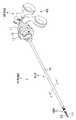
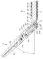
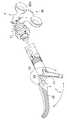
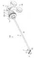
図1は外科用処置具を説明する図、図2は外科用処置具の分解状態を説明する図、図3は処置部ユニットの先端部の構成を説明する図、図4は挿入管ユニットの先端部の構成を説明する図、図5は図1のA−A線断面図、図6は連結固定状態の処置部ユニット及び挿入管ユニットの先端部を示す図、図7は図6のB−B線断面図、図8は連結状態の処置部ユニット及び挿入管ユニットからユニット着脱部材、回動ベース、先端カバー及び挿入管を取り外した状態の構成を説明する図、図9は挿入管ユニットの基端部の構成及びこの挿入管ユニットの基端部に配置された処置部回転ユニット及びこの処置部回転ユニットに配置された把持操作ユニットの構成を説明する図、図10は図9の主要部の構成を具体的に説明する拡大図である。
【0024】
図11は回動ハンドルの操作と処置部を構成する第1処置片及び第2処置片の開閉動作との関係を説明する図、図12は回動ハンドルの動作とボール部の移動変化状態の関係を説明する図、図13は連結ピンの移動と第1処置片及び第2処置片の開閉動作との関係を説明する図、図14は処置部操作棒の先端部の移動と第1処置片及び第2処置片の開閉動作との関係を説明する図、図15は第3ノブの回動操作と処置部の回動状態との関係を説明する図、図16は第3ノブの回動操作と連結固定ネジの移動変化状態の関係を説明する図、図17は回動ベース操作棒の先端部の移動と処置部の回動状態との関係を説明する図、図18は回動ベース操作棒の移動状態とジョイント部材の屈曲状態の関係を説明する図、図19は第1ノブの回動操作と処置部の旋回状態の関係を説明する図、図20は第1ノブの回動操作と駆動棒受けの回動状態との関係を説明する図、図21は処置部操作棒の回動状態と処置部の旋回状態との関係を説明する図、図22は回動ハンドル及び第3ノブを操作したときの処置部の作用を説明する図、図23は処置部操作棒及び回動ベース操作棒の移動状態と処置部の回動動作及びジョイント部材の屈曲状態、第1処置片及び第2処置片の開閉動作とを説明する断面図、図24は処置部操作棒及び回動ベース操作棒の移動状態と処置部の回動動作及びジョイント部材の屈曲状態、第1処置片及び第2処置片の開閉動作とを説明する斜視図、図25は回動ハンドル及び第1ノブを操作したときの処置部の作用を説明する図、図26は第1ノブ及び第3ノブを操作したときの処置部の作用を説明する図、図27は回動ハンドル及び第1ノブ及び第3ノブを操作したときの処置部の作用を説明する図である。
【0025】
図1に示すように本実施形態の外科用処置具1は、剛性を有する一対の処置片である第1処置片21及び第2処置片22を開閉自在に構成した例えば剥離鉗子である外科的処置部(以下、処置部と略記する)2と、細長な挿入管30を有する挿入部3と、前記処置部2の第1処置片21及び第2処置片22を開閉操作する処置部開閉操作部80を備えた、把持部を兼ねる把持操作部4とで主に構成されている。
【0026】
前記挿入部3の基端側で、かつ前記把持操作部4近傍には、この把持操作部4側から順に後述する略円形の回動操作部となる第1ノブ11、第2ノブ12、第3ノブ13が配設されている。このことによって、術者が固定ハンドル81及び回動ハンドル82を例えば薬指と親指で保持した状態で、残りの中指、人指し指を利用し各ノブ11、12、13の操作を行えるようになっている。つまり、外科用処置具1の全ての操作を、術者の片手で実行可能な構成にしている。
【0027】
図2に示すように前記外科用処置具1は、前記処置部2等を備えた処置部ユニット5と、前記第2ノブ12、前記第3ノブ13及び前記挿入管30等を備えた挿入管ユニット6と、第1ノブ11を備えた処置部回転ユニット7と、前記処置部開閉操作部80を構成する把持操作ユニット8とに着脱自在に分離される構成になっている。
【0028】
図2及び図3に示すように前記処置部ユニット5は、前記処置片21、22と、これら処置片21、22の基端部に連結される管状の処置部ベース23と、この処置部ベース23の基端部に遊嵌配置される環状で後述するように内周面に雌ネジ部(図7の符号24a参照)を形成した処置部ユニット着脱部材(以下、ユニット着脱部材と略記する)24と、前記処置部2を開閉操作する剛体部材で所定長さ寸法に形成した処置部操作棒9とで主に構成されている。この処置部操作棒9の基端部にはボール部9aを有する回転駆動棒9bが一体的に配置される。この回転駆動棒9bの側面部所定位置には後述する平面部(図10の符号9c、9d参照)が形成してある。
【0029】
なお、前記処置部操作棒9と前記処置部2とは後述する連結部である連結部材(図7の符号28参照)及び二連のユニバーサルジョイント25A、25Bを備えた所定形状のジョイント部材25等を介して連結される構成である。このため、前記処置部操作棒9の先端部及び前記連結部材28の基端部には前記ジョイント部材25との連結部となる断面形状を略凹字形状に形成した突起部9e、28aが設けられている。
【0030】
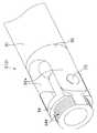
図2及び図4に示すように前記挿入管ユニット6は、前記挿入部3を構成する挿入管30及び先端カバー32と、この挿入管30の基端部に配設された第2ノブ12及び第3ノブ13とで主に構成されている。
前記挿入管30の先端側開口部には断面形状が略凹字形状の突起部32aを先端側に形成した先端カバー32が固設されている。この先端カバー32の突起部32a内には回動軸である一対の回動ベース回動ピン33を介して、先端部に前記雌ネジ部24aに螺合する雄ネジ部34aを形成した、管状の回動ベース34が回動自在に連結されている。
【0031】
なお、前記挿入管30内には前記回動ベース34を回動操作する剛体部材で所定長さ寸法に形成した後述する回動ベース操作棒が進退自在に挿通配置されており、この回動ベース操作棒の先端部は前記回動ベース34の所定部位に後述するように回動自在に連結されている。
【0032】
図5に示すように前記挿入部3を構成する挿入管30は、例えばステンレス部材等、剛性を有する細長で管状の本体管部37と、この本体管部37の内孔を複数の領域に分割する、断面形状を所定形状に形成した、前記本体管部37と同様に剛性を有する領域形成部材である細長な領域形成管38と、前記本体管部37を被覆する絶縁被覆39とで構成されている。
【0033】
本実施形態の領域形成管38は、前記本体管部37の内周面に密着配置されるように曲面で構成した外周曲面部38aと、直線で構成した直線部38bとを有している。そして、前記領域形成管38の内部空間である第1空間3aに前記第1処置片21と第2処置片22とで構成された処置部2を開閉させる開閉リンク機構を構成する前記処置部操作棒9が軸方向に進退自在に配置される。
【0034】
一方、前記領域形成管38の直線部38bの外面と前記本体管部37の内周面とが形成する内部空間である第2空間3bには挿入部の長手軸方向に対する前記処置部2の回動角度を後述する角度θの範囲で変化させる回動リンク機構を構成する断面形状を長方形に形成した回動ベース操作棒10が配置される。
つまり、前記処置部操作棒9と前記回動ベース操作棒10とは挿入部3内の所定空間内に軸方向に対して平行で進退自在に配置されている。そして、図に示すように前記処置部操作棒9を前記挿入部3の略中心に配置し、前記回動ベース操作棒10を前記挿入部3の中心より図中の下側に偏った位置に配置している。
【0035】
なお、前記第2空間3bの断面形状(開口寸法)は、この第2空間3bに配置される比較的厚み寸法が薄く、かつ長手方向に細長な回動ベース操作棒10が軸方向に進退して力を伝達するとき、座屈を防止して軸方向への力の伝達を確実に行えるように、この回動ベース操作棒10の断面形状(厚み寸法)を考慮して形成してある。また、本実施形態においては領域形成部材を管状部材としているがこの領域形成部材は管状部材に限定されものではなく、板部材等であってもよく、前記本体管部37の内孔に所定寸法の板部材を配置して形成されるそれぞれの空間に、所定の断面形状に形成した処置部操作棒9や回動ベース操作棒10を挿通配置させる構成であってもよい。
【0036】
図6及び図7に示すように前記処置部ユニット5の先端部と挿入管ユニット6の先端部とは前記処置部操作棒9を前記挿入管30の第1空間3a内に挿通配置させた状態で一体的に連結固定されるようになっている。
【0037】
前記ユニット着脱部材24は、このユニット着脱部材24に形成してある突起部24bを、前記処置部ベース23の基端部側に形成されている凹部23aに係入配置させて回動自在に構成される。したがって、前記ユニット着脱部材24を所定方向に回転させて、前記雌ネジ部24aと前記雄ネジ部34aとを螺合させていくことによって、ユニット着脱部材24は回動ベース34に螺合固定され、この状態において前記処置部ベース23は前記回動ベース34に対して軸まわりに回転可能な状態に保持されることになる。一方、この螺合固定状態で、前記ユニット着脱部材24を逆方向に回転させていくことによって、前記雌ネジ部24aと前記雄ネジ部34aとの螺合状態が解除されて、前記処置部ユニット5と前記挿入管ユニット6との分離を行える。
【0038】
なお、前記処置部ユニット5と挿入管ユニット6とを螺合固定状態にしたとき、前記挿入管ユニット6の基端面側から図示は省略するが前記処置部操作棒9の基端部及び回転駆動棒9bが所定量、突出した状態になる。
【0039】
図7に示すように前記回動ベース34の所定位置には前記回動ベース操作棒10の先端部が、回動ベース操作棒先端保持ピン(以下、回動保持ピンと略記する)35を介して回動自在に連結されている。この回動保持ピン35は、前記回動ベース回動ピン33と平行な位置関係で配置されている。
【0040】
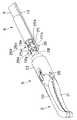
一方、前記処置部ベース23の先端側には第1処置片開閉ピン26を介して前記第1処置片21の中途部が回動自在に軸支されている。また、前記第1処置片21の基端部と前記第2処置片22の中途部とは処置部回動ピン27を介して回動自在に軸支されている。この処置部回動ピン27は、前記第1処置片開閉ピン26と平行な位置関係で配設されている。このことによって、前記第1処置片21と前記第2処置片22とは、処置部回動ピン27を支点にして相互に回動自在な構成になっている。
【0041】
前記処置部2を構成する第2処置片22と前記処置部操作棒9とは略円柱形状に形成した剛性を有する連結部材28及び前記ジョイント部材25を介して連結されている。具体的に、この連結部材28の先端部と前記第2処置片22の基端部とは連結ピン29によって回動自在に連結され、この連結部材28の突起部28aと前記処置部操作棒9の突起部9eとはジョイント部材25によって後述するように回動自在に連結されている。なお、前記連結ピン29も前記第1処置片開閉ピン26と平行な位置関係である。
【0042】
図7及び図8に示すように前記連結部材28の突起部28aと、前記ジョイント部材25の先端側とは第1ジョイントピン25a及び第2ジョイントピン25bによってそれぞれ回動自在に連結されている。また、前記ジョイント部材25の基端側と前記処置部操作棒9の突起部9eとは前記第1ジョイントピン25aと平行な位置関係である第3ジョイントピン25c及び前記第2ジョイントピン25bと平行な位置関係である第4ジョイントピン25dによってそれぞれ回動自在に連結されている。つまり、前記ジョイント部材25は、所謂、カルダン継ぎ手、十字継ぎ手と呼ばれるユニバーサルジョイントを二連にした構成である。
【0043】
そして、前記処置部操作棒9の外周面は、前記先端カバー32の内周面に当接して挿入部3の主軸である長手軸方向に沿って進退するようになっている。また、前記連結部材28の外周面も前記処置部ベース23の内周面に当接するように構成されている。このことによって、前記連結部材28は前記処置部ベース23の軸方向に沿って進退する。さらに、前記処置部操作棒9を回動させることによって、前記ジョイント部材25及び連結部材28が先端カバー32及び回動ベース34の内部で回動する。又、前記連結部材28に連結された連結ピン29、第2処置片22、処置部回動ピン27、第1処置片21、第1処置片開閉ピン26及び処置部ベース23が前記先端カバー32及び回動ベース34に対して軸まわりに回転(回動)することになる。
【0044】
なお、前記第1ジョイントピン25a及び第2ジョイントピン25b等で構成されたジョイント部材25の先端側に位置する第1ユニバーサルジョイント25Aと、前記第3ジョイントピン25c及び第4ジョイントピン25d等で構成されたジョイント部材25の基端側に位置する第2ユニバーサルジョイント25Bとは各ユニバーサルジョイント25A、25Bの前後の回転軸が45度の角度を成す範囲で回転運動を伝達することが可能なように構成されている。
【0045】
そして、本実施形態においては、前記処置部操作棒9の先端部を最も基端側に配置させた状態のとき、前記図1、図6ないし図8に示すように前記第1処置片21と前記第2処置片22とで構成される処置部2が第1終端状態である閉状態になっている。このとき、前記第1ユニバーサルジョイント25Aの中心点と前記回動ベース回動ピン33の中心軸とが一致するように構成されている。
【0046】
一方、後述する図13に示すように前記処置部操作棒9の先端部を最も先端側に移動配置させた状態にしたとき、前記ジョイント部材25、連結部材28及び前記第2処置片22の基端部が最先端側に移動されて、前記処置部2を構成する第1処置片21と第2処置片22とが第2終端状態である最大開状態になる。このとき、前記第2ユニバーサルジョイント25Bの中心点と前記回動ベース回動ピン33の中心軸とが一致するように構成されている。
【0047】
つまり、前記ジョイント部材25の第1ユニバーサルジョイント25Aの中心点と、第2ユニバーサルジョイント25Bの中心点との間隔を、上述の関係が成立するように設定している。
【0048】
なお、前記ユニット着脱部材24の外周表面には回動操作を容易、且つ確実に行えるように、例えば滑り止めとなるローレット等の加工が施してある。また、前記第1処置片21及び前記第2処置片22にはそれぞれ図13に示すような把持面21a及び把持面22aが相対して設けられている。これら把持面21a、22aには必要に応じた凹凸加工等を施して把持対象物である生体組織等を確実に把持することができるようにしている。さらに、前記第1処置片21及び第2処置片22は、図示された形状の剥離鉗子に限定されるものではなく、所望の形状に形成して構成した剥離鉗子、或いは鋏鉗子、把持鉗子等であってもよい。
【0049】
図2及び図9に示すように前記挿入管ユニット6の基端部に配設されている第2ノブ12にはリリース機構である第1着脱機構部91が設けられており、この第1着脱機構部91を介して前記第1ノブ11を備える処置部回転ユニット7が着脱自在な構成になっている。また、この第1ノブ11にはリリース機構である第2着脱機構部92が設けられており、この第2着脱機構部92を介して前記把持操作ユニット8との着脱を行える構成になっている。
【0050】
まず、前記着脱機構部91、92の構成を説明する。
図10に示すように前記第1着脱機構部91及び前記第2着脱機構部92は、弾性部材で形成したボタン部93と、このボタン部93が配置される剛性を有するボタン軸94と、このボタン軸94の先端部に螺合によって一体固定される所定形状の爪部材95とで構成されている。前記爪部材95は、前記第1着脱機構部91と前記第2着脱機構部92とでは形状が異なっており、本図においては第1着脱機構部91の爪部材を符号95aで表し、第2着脱機構部92の爪部材を符号95bで表している。
【0051】
前記着脱機構部91、92の爪部材95a、95bは無負荷状態においては、つまり、術者が手指で押圧していない状態のときには、前記ボタン部93の有する弾性力によって図に示すように上方向に移動した状態になっている。
【0052】
そして、この状態で、術者が前記ボタン部93を弾性力に抗して押し込み操作することによって、前記ボタン軸94が図中の下方向に移動される。このことにより、このボタン軸94に一体な爪部材95a、95bが下方向に移動するようになっている。
【0053】
前記押し込み操作状態から術者が再び前記ボタン部93から手指を離すことによって、前記ボタン軸94が前記ボタン部93の弾性力によって図中の上方向に移動されて、前記爪部材95a、95bも上方向に移動するようになっている。
【0054】
次に、図9及び図10を参照して前記把持操作ユニット8の構成を説明する。
前記把持操作ユニット8は、処置部開閉操作部80を構成する固定ハンドル81及び回動ハンドル82とで主に構成されている。この固定ハンドル81及び回動ハンドル82の所定部位には使用者の指が挿通配置される貫通孔が形成されており、この貫通孔には操作時の指への負担を軽減するリンゲ81a,82bがそれぞれ配設されている。
【0055】
前記固定ハンドル81と前記回動ハンドル82とはハンドルピン83を介して回動自在に軸支されている。したがって、前記回動ハンドル82は前記ハンドルピン83を中心にして図の矢印a方向及び矢印b方向に回動するようになっている。
【0056】
前記回動ハンドル82の先端側所定部には前記回転駆動棒9bのボール部9aが着脱自在に遊嵌配置される駆動棒受け84が形成されている。この駆動棒受け84に前記ボール部9aを係入配置させることによって、前記回転駆動棒9bは回動可能な状態で保持される。
【0057】
一方、前記固定ハンドル81の先端部には前記処置部回転ユニット7に設けた第2着脱機構部92との着脱部を構成するハンドルベース85が設けられている。このハンドルベース85の先端部には前記第2着脱機構部92を構成する爪部材95bの爪部96bと係合する係合部85aが設けられている。
【0058】
前記ハンドルベース85の内孔には略管状の駆動棒受け86が軸まわりに回動可能に挿入配置されている。この駆動棒受け86の先端部には軸方向に細長なガイド部86aが形成されている。このガイド部86aには後述する第1ノブベース(符号44参照)の基端部に配設された、例えば一対の回動伝達ガイドピン44bの先端部がそれぞれ係入配置されるようになっている。
【0059】
前記駆動棒受け86の内孔には前記回転駆動棒9bの側面部に形成された平面部9c、9dが当接配置される当接平面86c、86dが形成されている。このため、前記駆動棒受け86内に回転駆動棒9bが挿通配置されている状態で、前記駆動棒受け86を回転させることによって、この駆動棒受け86の回転に追従して前記処置部操作棒9が回転するようになっている。つまり、前記処置部操作棒9は、前記駆動棒受け86の回動に追従して360度回転する構成になっている。
【0060】
前記固定ハンドル81には、前記駆動棒受け84に向けて突出する回転駆動棒9bの側周面に密着して、術中に第1空間3a及び第2空間3bと外部とが連通状態になって腹腔内圧が低下することを抑止する、気密キャップ87が設けられている。なお、符号88は前記固定ハンドル81に配設された高周波入力ピンである。
【0061】
次いで、図10を参照して処置部回転ユニット7の構成を説明する。
前記処置部回転ユニット7は、第1ノブ11を形成した管状の第1ノブ本体41と、第1ノブベース44とで主に構成されている。前記第1ノブベース44は、前記第1ノブ本体41の孔部に挿通配置された状態で、第1ノブ締結部材45aによって、この第1ノブ本体41に一体的に固定されている。この第1ノブベース44の基端部には前記駆動棒受け86と一体に回転するように前記ガイド部86aに係入配置されて規制を行う回動伝達ガイドピン44bが設けられている。
【0062】
前記回動伝達ガイドピン44bを前記ガイド部86aに係入配置させた状態で、前記第1ノブ本体41を回動させることによって、この第1ノブ本体41の回動動作に、前記第1ノブベース44、駆動棒受け86、回転駆動棒9bが連動して、前記処置部操作棒9が回動動作するようになっている。
【0063】
なお、前記処置部回転ユニット7を構成する第1ノブ本体41の所定位置には前記第2着脱機構部92が配置されている。また、前記第1ノブベース44の基端部所定位置には、この第1ノブベース44と前記ハンドルベース85との間の気密を保持するための第1気密シール52aが配設される周溝44aが形成されている。
【0064】
次に、図10を参照して前記挿入管ユニット6の基端部の構成を説明する。
前記挿入管30に一体的に配置される第2ノブ12は、この第2ノブ12を形成した管状の第2ノブ本体42と、第2ノブベース46と、ノブ先端カバー部材47とで主に構成されている。また、前記第2ノブ本体42には前記第3ノブ13を形成した管状の第3ノブ本体43と、この第3ノブ本体43に螺合状態で一体配置される進退部材48とが配置されている。
【0065】
前記挿入管30の基端部所定位置にはベース締結部材45bを介して前記第2ノブベース46が固定されている。そして、この第2ノブベース46には第2ノブ締結部材45cを介して前記第2ノブ本体42が一体的に固設されている。このことによって、前記挿入管30の基端部所定位置に第2ノブ12が配置される。
【0066】
したがって、前記第2ノブ本体42を回動させることによって、この第2ノブ本体42の回動動作に、前記第2ノブベース46が連動して、前記挿入管30が回動動作するようになっている。
【0067】
前記第2ノブ本体42には、前記第3ノブ本体43が回動自在に配置されるフランジ部42aと、前記進退部材48が軸方向に進退自在に配置されるとともに、前記第1着脱機構部91が配置される胴部42bとが設けられている。
【0068】
前記第2ノブ本体42の胴部42b及び前記第2ノブベース46の所定位置には前記第2空間3bに挿通配置される回動ベース操作棒10の基端部へのアクセスを可能にする所定径寸法の貫通孔49が形成されている。この貫通孔49には前記進退部材48と回動ベース操作棒10の基端部とを一体的に連結固定する連結固定ネジ50が配置されるようになっている。
【0069】
前記第3ノブ本体43は、前記第2ノブ本体42のフランジ部42aに対して第3ノブオサエ43a及び固定ネジ43bによって回動可能に設置される。この第3ノブ本体43の先端側内周面には雌ネジ部43cが形成されている。一方、前記進退部材48の基端部には前記雌ネジ部43cと螺合する雄ネジ部48aが形成されている。そして、この進退部材48の雄ネジ部48aと前記第3ノブ本体43の雌ネジ部43cとを螺合させた状態で前記第2ノブ本体42の胴部42bの所定位置に配置されている。
【0070】
したがって、前記第2ノブ本体42に回動自在に配置されている第3ノブ本体43を回動操作することによって、前記雌ネジ部43cと雄ネジ部48aとの螺合状態が変化していく。すると、前記進退部材48が胴部42b上を軸方向に進退移動する。そして、この進退部材48が軸方向の進退移動に連動して、この進退部材48に前記連結固定ネジ50を介して一体に連結固定されている回動ベース操作棒10が進退移動するようになっている。
【0071】
前記第2ノブ本体42の先端部には先端凹部42cが形成されており、この先端凹部には前記ノブ先端カバー部材47の先端部47aが配置されるようになっている。この先端凹部42c内には所定の弾性力を有するOリング51が配置されている。
【0072】
前記Oリング51は、前記ノブ先端カバー部材47の先端面で押圧されるように構成されており、このOリング51を前記ノブ先端カバー部材47の先端面で押圧して径方向に拡径するように変形させることによって、前記挿入管30を構成する絶縁被覆39にOリング51が密着状態となって、固定を確実なものとしている。
【0073】
前記進退部材48が配置される胴部42bの外周表面であって前記貫通孔49の対向する外周側には一対の周状凹部42dが形成されており、この周状凹部内には胴部42bの外周面と進退部材48の内周面との間の気密を保持して、前記貫通孔49を介して第2空間3bと外部とが連通状態になって腹腔内圧が低下することを抑止する第2気密シール52bが配設されている。
【0074】
前記処置部回転ユニット7を挿入管ユニット6に一体的に連結配置させる際、この挿入管ユニット6を構成する第2ノブベース46の基端部の外周面に前記処置部回転ユニット7を構成する第1ノブベース44の内周面が配置される。そして、前記第2ノブベース46の基端部には、この第2ノブベース46の外周面と前記第1ノブベース44の内周面との間の気密を保持する第3気密シール52cを配設するための周溝46aが形成されている。
【0075】
なお、前記第1ノブ11、第2ノブ12、第3ノブ13の径寸法は、前記処置部開閉操作部80側から先端側に向かうにしたがって径寸法が大径になるように形成して操作性の向上を図った構成になっている。
【0076】
また、前記第1ノブベース44の先端部には、前記挿入管ユニット6に配置された第1着脱機構部91を構成する爪部材95aの爪部96aが着脱自在に係合される係合凹部44cが形成されている。
【0077】
さらに、前記第1ノブ本体41、第2ノブ本体42及び第3ノブ本体43の回動操作部となる外周面には術者の手指で回動操作を容易、且つ確実に行えるように、例えば滑り止めとなる凹凸加工が施してある。
【0078】
そして、例えば処置部ユニット5、挿入管ユニット6及び処置部回転ユニット7を組み付けた状態にして、この処置部回転ユニット7に把持操作ユニット8を組み付けることによって前記図1で示した外科用処置具1が構成される。このとき、挿入管ユニット6の基端部に配置された処置部回転ユニット7を前記把持操作ユニット8のハンドルベース85に係合配置させるとともに、前記処置部ユニット5を構成する処置部操作棒9に一体な回転駆動棒9bのボール部9aを前記駆動棒受け84に係入配置させる。
【0079】
上述のように構成した外科用処置具1の作用を説明する。
前記外科用処置具1は、前記処置部開閉操作部80、第1ノブ11、第2ノブ12、第3ノブ13をそれぞれ適宜手元操作することによって、前記処置部2が所定の動作をするように構成されている。
以下、図面を参照して処置部開閉操作部80、第1ノブ11、第2ノブ12、第3ノブ13の手元操作と処置部2の動作との関係を説明する。
【0080】
処置部開閉操作部80を単独に操作したときの作用を説明する。
前記図1に示した状態の前記外科用処置具1の処置部開閉操作部80の回動ハンドル82を、図11の矢印a方向に移動操作していくことによって、前記外科用処置具1の処置部2を構成する第1処置片21と第2処置片22とが、閉状態から開状態に変化する。そして、この開状態で前記回動ハンドル82を矢印b方向に移動操作することによって、開状態であった前記第1処置片21と第2処置片22とが閉状態に変化していく。
【0081】
具体的には、図12に示すように前記回動ハンドル82を、一点鎖線に示す位置から実線に示す位置まで回動操作することによって、前記ボール部9aが距離L1だけ外科用処置具1の長手軸方向に対して平行に移動する。このことによって、図13及び図14に示すように前記処置部操作棒9も距離L1だけ平行移動して、この処置部操作棒9の移動に連動して、前記ジョイント部材25及び連結部材28に配置されている連結ピン29が距離L1だけ平行移動して、前記処置部2を構成する第1処置片21と第2処置片22とが相互に移動して矢印に示すように開閉動作する。
【0082】
第3ノブ13を単独に操作したときの作用を説明する。
前記図1に示した状態の前記外科用処置具1の第3ノブ13を、図15に示すように矢印c方向に回転操作させることによって、前記外科用処置具1の長手軸に対して水平な位置に配置されていた処置部2がこの長手軸に対して角度θだけ傾いた状態に変化する。そして、この処置部2が角度θで傾いた状態で、前記第3ノブ13を矢印d方向に回転操作することによって、前記処置部2は長手軸に向かって、つまり、前記角度θを小さくするように傾き角度が変化していく。なお、前記第3ノブ13を矢印d方向に操作させることによって処置部2が角度θ傾き、矢印c方向に回転操作することによって前記角度θが小さくなるように構成してもよい。
【0083】
具体的には、前記第3ノブ13を矢印c又は矢印d方向に回動操作することによって、図16に示すように前記第3ノブ13が形成されている第3ノブ本体43の雌ネジ部43cと雄ネジ部48aが螺合状態になっている進退部材48が、前記第2ノブ本体42の胴部42b上を一点鎖線に示す位置から実線に示す位置まで、距離L2だけ移動する。
【0084】
このことによって、前記進退部材48に連結固定ネジ50によって一体に連結固定されている回動ベース操作棒10も距離L2だけ外科用処置具1の長手軸方向に対して平行に移動する。
【0085】
すると、図17及び図18に示すように前記回動ベース操作棒10の先端部に位置する回動保持ピン35が距離L2だけ平行移動する。すると、前記回動ベース34が前記回動ベース回動ピン33を中心に回動する動作が引き起こされる。このことによって、前記処置部2が前記外科用処置具1の長手軸方向に対して水平な位置から図中上方を向いた所定角度の範囲を回動する。
【0086】
このとき、前記ジョイント部材25の第2ジョイントピン25bを中心にして前記連結部材28が0度から45度の範囲を回動するので、前記処置部2が前記外科用処置具1の長手軸方向に対して水平な状態から45度傾いた範囲を回動動作する。
【0087】
第2ノブ12を単独に操作したときの作用について説明する。
前記図1に示した状態の前記外科用処置具1の第2ノブ12を回動操作することによって、この第2ノブ12に一体に配置されている挿入管30が回動操作方向に回転する。このとき、前記挿入管30の先端部に固定されている先端カバー32も前記挿入管30と同様に回転することによって、この先端カバー32に回動ベース回動ピン33を介して取り付けられている回動ベース34も同様に回転する。
【0088】
つまり、前記第2ノブ12を回動操作することによって、前記挿入管30とともに先端カバー32、回動ベース34を回動移動させて、この先端カバー32に回動ベース回動ピン33を介して回動自在に配置されている回動ベース34の回動方向を所望の向きに設定することができるようになっている。
【0089】
第1ノブ11を単独に操作したときの作用を説明する。
前記図1に示した状態の前記外科用処置具1の第1ノブ11を、図19に示すように矢印e方向に例えば90度だけ回転操作していくことによって、前記外科用処置具1の長手軸を中心にして前記処置部2が回転して、前記処置部ベース23に配置されている第1処置片開閉ピン26が例えば図6の正面を向いていた状態から図19中の上方を向いた状態に変化する。そして、この状態で、前記第1ノブ11を矢印f方向に回転操作することによって、前記処置部2は前記外科用処置具1の長手軸を中心に逆方向に回転する。つまり、前記第1ノブ11の回動操作に対応して、前記処置部ベース23が矢印に示すように回動動作されて、前記処置部2が外科用処置具1の長手軸を中心に旋回動作する。
【0090】
具体的には、前記第1ノブ11を回動操作することによって、図20に示すようにこの第1ノブ11を形成する第1ノブ本体41に一体な第1ノブベース44が回動する。このとき、前記図10で示したように第1ノブベース44の基端部に設けられている回動伝達ガイドピン44bの先端部が前記固定ハンドル81のハンドルベース85の内部に配置されている駆動棒受け86のガイド部86aに係入配置された構成であるため、この第1ノブベース44の回動に連動して駆動棒受け86が回動される。すると、この駆動棒受け86の当接平面86c、86dに対して前記回転駆動棒9bの平面部9c、9dが当接配置されていることによって、前記駆動棒受け86の回転に連動して回転駆動棒9bが回動されて処置部操作棒9も回動動作する。
【0091】
このとき、図21に示すように前記処置部操作棒9の矢印に示す回動に伴って、前記ジョイント部材25及び連結部材28を介して連結されている処置部2が回動する。ここで、前記ジョイント部材25は、上述したようにユニバーサルジョイントとして構成されているので、前記処置部操作棒9の回動運動に伴ってこのジョイント部材25も回動して前記連結部材28が回動を開始する。
【0092】
そして、前記連結部材28が回動動作することによって、この連結部材28に前記連結ピン29を介して連結された第2処置片22が回動される。すると、前記処置部回動ピン27を介して第2処置片22に連結されている第1処置片21が回動する。ここで、この第1処置片21が処置部ベース23に第1処置片開閉ピン26を介して回動自在に軸支されていることによって、処置部ベース23が回動されて処置部2が外科用処置具1の長手軸を中心に旋回する。
【0093】
したがって、第1ノブ11を回動操作することによって、処置部操作棒9の先端部に連結されている処置部2を外科用処置具1の長手軸を中心に旋回させて、処置部2の向きは任意の方向に設定される。
【0094】
ここで、図面を参照して処置部開閉操作部80、第1ノブ11、第2ノブ12、第3ノブ13の少なくとも2つを組み合わせて手元操作したときの処置部2の動作を説明する。
【0095】
まず、第3ノブ13を操作して処置部2を角度θの範囲で回動させた状態で、回動ハンドル82を操作したときの作用を説明する。
図22に示すように前記第3ノブ13を回動操作した状態で、前記処置部開閉操作部80の回動ハンドル82を回動操作すると、前記処置部2が角度θの範囲で傾いた状態で、前記処置部操作棒9が進退動作されて、前記処置部2を構成する第1処置片21と第2処置片22とが矢印に示すように開閉動作する。
【0096】
具体的に、前記処置部2が角度θの範囲で傾いた状態で、前記処置部操作棒9が進退されることによって、図23及び図24に示すようにジョイント部材25及び連結部材28も進退されて、第1処置片21及び第2処置片22の相互開閉動作が行われる。
【0097】
このとき、前記処置部操作棒9の進退に伴って、前記連結部材28とジョイント部材25とが第2ジョイントピン25bを中心に相対的に回動するとともに、このジョイント部材25と処置部操作棒9とが第4ジョイントピン25dを中心にして相対的に回動して前記第1処置片21及び第2処置片22が開閉動作される。
【0098】
なお、この逆に、前記回動ハンドル82を操作して処置部2を開状態にして、前記第3ノブ13を回動操作すると、前記第1処置片21と第2処置片22とが開状態のままで処置部2の角度θを変化させられる。また、前記回動ハンドル82及び前記第3ノブ13を操作した状態で、前記第2ノブ12を回動操作することは可能であり、このことによって前記処置部2の回動方向が任意に設定される。
【0099】
次に、第1ノブ11を操作して処置部2を所定量旋回させた状態で、回動ハンドル82を操作したときの作用を説明する。
図25に示すように第1ノブ11を操作して前記処置部2を旋回させた状態で、回動ハンドル82を操作することによって、処置部2を旋回させた状態で、この処置部2を構成する第1処置片21と第2処置片22との開閉動作を行える。この逆に、前記回動ハンドル82を操作して処置部2を開状態にして、前記第1ノブ11を回動操作することによって、開状態の処置部2を外科用処置具1の長手軸を中心に旋回させて、処置部2の向きは任意の方向に設定される。
【0100】
なお、前記回動ハンドル82及び前記第1ノブ11を操作した状態で、前記第2ノブ12を回動操作することは可能であり、このことによって前記処置部2の回動方向が任意に設定される。
【0101】
次いで、第1ノブ11を操作して処置部2を所定量旋回させた状態で、第3ノブ13を操作したときの作用を説明する。
図26に示すように第1ノブ11を操作して前記処置部2を旋回させた状態で、第3ノブ13を操作することによって、旋回した状態で外科用処置具1の長手軸に対して水平な位置に配置されていた処置部2が、この長手軸に対して角度θだけ傾いた状態に変化する。この逆に、前記第3ノブ13を操作して処置部2を傾けた状態で、前記第1ノブ11を回動操作すると、前記ジョイント部材25の先端側に位置する第1ユニバーサルジョイント25Aと、基端側に位置する第2ユニバーサルジョイント25Bとを、これらユニバーサルジョイント25A、25Bの前後の回転軸が45度傾いた状態で回転運動を伝達可能に構成してあるので、傾いた状態の処置部2がその軸まわりに旋回動作する。
【0102】
なお、前記第1ノブ11及び第3ノブ13を操作した状態で、前記第2ノブ12を回動操作することは可能であり、このことによって前記処置部2の回動方向が任意に設定される。また、図27に示すように前記第1ノブ11及び第3ノブ13を操作した状態で、前記回動ハンドル82を回動操作することによって、旋回した状態で、前記長手軸に対して角度θで傾いた状態の処置部2を構成する第1処置片21と第2処置片22との開閉動作を行える。
【0103】
本実施形態においては、上述したように前記処置部2を回動させる操作と、処置部2を旋回させる操作と、処置部2の回動方向を任意に設定する操作と、処置部2を構成する第1処置片21及び第2処置片22を開閉させる操作を、任意に組み合わせて行えるようになっている。
【0104】
これらのことによって、処置部開閉操作部、第1ノブ、第2ノブ、第3ノブを適宜操作することによって、処置部を構成する第1処置片及び第2処置片を開閉操作するだけでなく、挿入管を回動させたり、処置部を回動或いは旋回させて、処置部と把持対象物との位置関係を所望の位置関係に容易に変化させられることができるとともに、処置部等が意図しない外力によって回動姿勢が変化してしまうことが確実に防止することができる。
【0105】
また、処置部を動作させるとき、力覚フィードバックのダイレクト感を得ながらの操作を行えるので、実使用における操作性及び実用性の向上を図ることができる。
【0106】
さらに、第1処置片及び第2処置片を開閉させる機構部及び処置部を回動させる機構部、処置部を旋回させる機構部、挿入管を回動させる機構部等、各機構部をピンによる連結、或いはネジによる締結等を構成の簡便化を図ることができる。
【0107】
又、外科用処置具を複数のユニットに分解可能に構成したことによって、使用後の洗浄を容易かつ短時間で行うことができる。
【0108】
なお、各ノブ11、12、13を操作する際、例えば人差し指で第2ノブ12を保持しながら中指で第3ノブ13を操作するといった使用方法を採用することによって、各ノブの回転を防止するロック機構を設けることなく、さらに簡便な外科用処置具が構成される。
【0109】
(第2の実施形態)
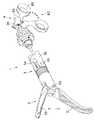
図28及び図29は本発明の第2の実施形態に係り、図28は第3ノブの構成が異なる外科用処置具を説明する図、図29の外科用処置具の作用を説明する図である。なお、本実施形態において前記第1実施形態と共通する構成部分については同符号を付して説明を省略する。
【0110】
図28に示すように本実施形態の外科用処置具100は、第3ノブ103が進退部材101に直接固定されて構成されている。この進退部材101は第2本体102に進退自在に配置されている。なお、進退部材101と回動ベース操作棒(不図示)とが連結固定ネジ50によって一体的に連結固定されている。
【0111】
したがって、前記第1実施形態では第3ノブ13を回動操作して回動ベース操作棒10を進退移動させる構成であったのに対し、本実施形態では第3ノブ103を矢印g方向又は矢印h方向に進退操作することによって、前記進退部材101を第2ノブ本体102に対して進退させて、前記回動ベース操作棒10を進退移動させるようになっている。
【0112】
つまり、図29に示すように前記第3ノブ103を進退操作することによって、この第3ノブ103に一体な進退部材101が進退移動されて、図の矢印に示すように前記回動ベース34が角度θの範囲を回動動作する。
【0113】
このように、第3ノブを第2ノブ本体に対して進退自在に配置された進退部材に一体に固定したことによって、処置部の回動操作をより素早く実行することができる。
【0114】
尚、本発明は、以上述べた実施形態のみに限定されるものではなく、発明の要旨を逸脱しない範囲で種々変形実施可能である。
【0115】
[付記]
以上詳述したような本発明の上記実施形態によれば、以下の如き構成を得ることができる。
【0116】
(1)把持部を兼ね、固定ハンドル及び回動ハンドルを備えた処置部開閉操作部と、
この処置部開閉操作部の回動ハンドルに連結され、前記回動ハンドルの操作に応じて進退移動する細長で剛性を有する処置部操作棒と、
この処置部操作棒が挿通配置される挿入部と、
この挿入部の先端部に、前記挿入部の長手軸に直交する向きに配置される回動軸を介して、回動自在に軸支される回動ベースと、
この回動ベースに先端部が連結され、進退移動によって前記回動ベースを回動軸に対して回動させる細長で剛性を有する回動ベース操作棒と、
前記回動ベースに連結され、前記処置部操作棒の進退動作に対応して開閉動作を行う外科的処置部を配置した、処置部ベースと、
この処置部ベースに配置された前記外科的処置部と前記処置部操作棒とを連結する剛性を有する連結部を構成する、複数のユニバーサルジョイントを有するジョイント部材と、
を具備する外科用処置具。
【0117】
(2)前記挿入部の基端部に前記処置部操作棒を回動させて、前記外科的処置部を旋回動作させる第1操作ノブを設けた付記1に記載の外科用処置具。
【0118】
(3)前記回動ハンドルの操作によって、前記処置部操作棒を進退移動させて、前記外科的処置部を第1終端状態又は第2終端状態に変化させるとき、
前記ジョイント部材は、前記外科的処置部が第1終端状態であるとき、前記ジョイント部材の先端側に位置するユニバーサルジョイントの中心が前記回動軸の軸中心に一致し、前記外科的処置部が第2終端状態であるとき、前記ジョイント部材の基端側に位置するユニバーサルジョイントの中心が前記回動軸の軸中心に一致する配置構成である付記1に記載の外科用処置具。
【0119】
(4)前記処置部操作棒は、前記処置部開閉操作部の回動ハンドルに着脱自在に連結され、前記処置部ベースは前記回動ベースに着脱自在に連結される付記1に記載の外科用処置具。
【0120】
(5)前記挿入部の基端部に前記挿入部を回動させて、回動自在構成された前記回動ベースの回動方向を変化させる第2操作ノブを設けた付記1に記載の外科用処置具。
【0121】
(6)前記挿入部の基端部に前記回動ベース操作棒を進退移動させて、前記回動ベースを前記回動軸に対して回動動作させる第3操作ノブを設けた付記1に記載の外科用処置具。
【0122】
(7)前記挿入部の基端部に複数のノブを配置するとき、前記処置部開閉操作部から離れた位置に配置されるノブの径寸法を大径に形成した付記1ないし付記6のいずれかに記載の外科用処置具。
【0123】
【発明の効果】
以上説明したように本発明によれば、挿入部の先端部に備えられた外科的処置部を、外科用処置具長手軸に直交する軸に対して回動可能であるとともに、その外科的処置部が任意の回動状態においてもその軸まわりに回転操作可能かつ開閉操作可能である。また、その外科的処置部の回動状態或いは回転状態の姿勢保持が確実に行え、さらにその開閉操作が確実に行える、操作性に優れた簡便な構成の外科用処置具を提供することができる。
【図面の簡単な説明】
【図1】図1ないし図27は本発明の第1実施形態にかかり、図1は外科用処置具を説明する図
【図2】外科用処置具の分解状態を説明する図
【図3】、図3は処置部ユニットの先端部の構成を説明する図
【図4】挿入管ユニットの先端部の構成を説明する図
【図5】図1のA−A線断面図
【図6】連結固定状態の処置部ユニット及び挿入管ユニットの先端部を示す図
【図7】図6のB−B線断面図
【図8】連結状態の処置部ユニット及び挿入管ユニットからユニット着脱部材、回動ベース、先端カバー及び挿入管を取り外した状態の構成を説明する図
【図9】挿入管ユニットの基端部の構成及びこの挿入管ユニットの基端部に配置された処置部回転ユニット及びこの処置部回転ユニットに配置された把持操作ユニットの構成を説明する図
【図10】図9の主要部の構成を具体的に説明する拡大図
【図11】図11ないし図27は外科用処置具の作用を説明する図であり、図11は回動ハンドルの操作と処置部を構成する第1処置片及び第2処置片の開閉動作との関係を説明する図
【図12】回動ハンドルの動作とボール部の移動変化状態の関係を説明する図
【図13】連結ピンの移動と第1処置片及び第2処置片の開閉動作との関係を説明する図
【図14】処置部操作棒の先端部の移動と第1処置片及び第2処置片の開閉動作との関係を説明する図
【図15】第3ノブの回動操作と処置部の回動状態との関係を説明する図
【図16】第3ノブの回動操作と連結固定ネジの移動変化状態の関係を説明する図
【図17】回動ベース操作棒の先端部の移動と処置部の回動状態との関係を説明する図
【図18】回動ベース操作棒の移動状態とジョイント部材の屈曲状態の関係を説明する図
【図19】第1ノブの回動操作と処置部の旋回状態の関係を説明する図
【図20】第1ノブの回動操作と駆動棒受けの回動状態との関係を説明する図
【図21】処置部操作棒の回動状態と処置部の旋回状態との関係を説明する図
【図22】回動ハンドル及び第3ノブを操作したときの処置部の作用を説明する図
【図23】処置部操作棒及び回動ベース操作棒の移動状態と処置部の回動動作及びジョイント部材の屈曲状態、第1処置片及び第2処置片の開閉動作とを説明する断面図
【図24】処置部操作棒及び回動ベース操作棒の移動状態と処置部の回動動作及びジョイント部材の屈曲状態、第1処置片及び第2処置片の開閉動作とを説明する斜視図
【図25】回動ハンドル及び第1ノブを操作したときの処置部の作用を説明する図
【図26】第1ノブ及び第3ノブを操作したときの処置部の作用を説明する図
【図27】回動ハンドル及び第1ノブ及び第3ノブを操作したときの処置部の作用を説明する図
【図28】図28及び図29は本発明の第2の実施形態に係り、図28は第3ノブの構成が異なる外科用処置具を説明する図
【図29】外科用処置具の作用を説明する図
【符号の説明】
1…外科用処置具
2…処置部
3…挿入部
4…把持操作部
9…処置部操作棒
10…回動ベース操作棒
11…第1ノブ
12…第2ノブ
13…第3ノブ
23…処置部ベース
25…ジョイント部材
28…連結部材
80…処置部開閉操作部[0001]
BACKGROUND OF THE INVENTION
The present invention relates to a surgical operation, particularly an endoscopic operation, by appropriately operating a surgical treatment section provided at a distal end portion of an insertion portion while an operator grasps an operation portion provided at a proximal end portion of the insertion portion. The present invention relates to a surgical treatment instrument used when performing a surgical operation under a mirror.
[0002]
[Prior art]
2. Description of the Related Art Conventionally, endoscopes that can perform observations and various treatments on a treatment site while observing a subject image obtained by inserting an endoscope having an elongated insertion portion into a body cavity or the like have been widely used. Yes. Also, in recent years, a trocar that guides an endoscope for observation into a body cavity and a trocar that guides a surgical treatment tool to a treatment site without laparotomy in order to reduce the invasion to a patient is inserted into the endoscope. Thus, endoscopic surgery or the like for performing treatment and treatment while observing a surgical treatment tool and a treatment site is performed.
[0003]
Surgical treatment tools used in endoscopic surgery and the like are elongated, and a surgical treatment portion (hereinafter also referred to as a treatment member) disposed at the distal end of the insertion portion is provided on the proximal side of the insertion portion. The operation unit is operated to operate.
[0004]
In US applications (hereinafter abbreviated as USP) 5,374,277, USP 5,549,637, USP 5,350,391, a treatment member disposed on the distal end side is attached to the main axis of the surgical instrument. In the rotated state, the treatment member can be rotated around its axis.
[0005]
Specifically, the surgical treatment instrument of USP 5,374,277 includes a rotation joint that allows the distal end portion to rotate with respect to the main axis of the surgical treatment instrument, and a treatment member is provided at the distal end side of the rotation joint. Has a mount. This mount is divided into a first mount on the distal end side and a second mount on the proximal end side by wrist means. As a result, the treatment member provided at the distal end portion of the first mount can be rotated around the axis on the distal end side with respect to the rotating joint.
[0006]
In the medical device having the joint portion of USP 5,549,637, the distal end portion can be rotated with respect to the main axis of the treatment instrument, and can be rotated around the distal end side axis of the rotational joint. A flexible mechanism such as a wire or cable is provided in the turning mechanism of the tip. As a mechanism for rotating the distal end side of the rotating joint around the axis, a spur gear or a bevel gear is used for each part such as the operating portion and the rotating joint portion, while a mechanism for operating the treatment member attached to the distal end. Is provided with a push rod-like member via a link part.
[0007]
In the laparoscopic apparatus of the USP 5,350,391, the turning operation of the treatment member provided at the tip is performed by one handle of the pair of operation handles, and the opening / closing movement operation of the treatment member is performed by the other handle. Format.
[0008]
[Patent Document 1]
USP 5,374,277
[0009]
[Patent Document 2]
USP 5,549,637
[0010]
[Patent Document 3]
USP 5,350,391
[0011]
[Problems to be solved by the invention]
However, in the surgical treatment instrument of the USP 5,374,277, the rotation operation itself is not configured to be remotely operated by an operation unit provided on the proximal end side of the surgical treatment instrument. For this reason, a problem arises in operability in the actual use situation. In addition, the angle at which the rotation operation can be performed can only select a discrete rotation angle such as 45 degrees or 90 degrees from a predetermined starting position, and the operability is poor. Further, since the cable member is employed in the opening / closing mechanism of the treatment member, there is no sense of unity (direct feeling) with the handle opening / closing operation during the actual opening / closing operation of the treatment member, and in particular, the operation of opening the treatment member is important. There is a possibility that inconvenience may occur in the peeling operation of the living tissue.
[0012]
Further, in the medical device having the joint part of USP 5,549,637, the rotation mechanism of the distal end part, the rotation mechanism around the axis of the distal end part, and the operation mechanism of the treatment member each require a unique structure. The configuration is very complex. In addition, there is a risk that actual operability may be impaired due to the generation of the insensitive region due to gear backlash or the like. Furthermore, since the turning operation is performed by a flexible member such as a wire or a cable, it is difficult to maintain the posture in the turning state.
[0013]
Further, in the laparoscopic instrument of USP 5,350,391, although it is in one plane, the pair of operation handles themselves are rotated with respect to the main axis of the treatment instrument. It may take a considerable amount of time to learn. In addition, the handle for controlling the rotation of the treatment member is provided with a lock mechanism. However, each time a desired posture is determined, an operation for operating / releasing the lock mechanism is required, which is cumbersome. Since the cable is used because the joint portion needs to pass through the opening / closing drive mechanism of the treatment member, it is difficult to obtain a direct feeling of force feedback in the opening / closing operation of the treatment member.
[0014]
The present invention has been made in view of the above circumstances, and is capable of rotating a surgical treatment portion provided at a distal end portion of an insertion portion with respect to an axis perpendicular to the longitudinal axis of a surgical treatment instrument. The surgical treatment section can be rotated around its axis and can be opened and closed even in any rotation state. It is another object of the present invention to provide a surgical treatment instrument with a simple configuration excellent in operability, which can reliably hold the rotated or rotated posture of the surgical treatment section and can reliably perform the opening / closing operation thereof. I have to.
[0015]
[Means for Solving the Problems]
The surgical treatment instrument of the present invention is connected to a treatment section opening / closing operation section that also serves as a gripping section and includes a fixed handle and a rotation handle, and a rotation handle of the treatment section opening / closing operation section. Move forward and backward according toAnd arranged rotatably A long and rigid treatment part operation rod, an insertion part through which the treatment part operation bar is inserted and arranged, and a rotation shaft arranged at the distal end of the insertion part in a direction perpendicular to the longitudinal axis of the insertion part A pivot base that is pivotally supported via the pivot base, and a distal end portion connected to the pivot base, and having an elongated and rigid shape that pivots the pivot base with respect to the pivot shaft by advancing and retreating. Rotating base operating rod and the rotating baseIn contrast, it is held rotatably around the axis. A surgical treatment base that arranges a surgical treatment section that opens and closes in response to the advancing / retreating operation of the treatment section operation rod, and the surgical treatment section that is disposed on the treatment section baseof One endBy a connecting pin that is in a positional relationship parallel to the rotation axis Freely rotatablePivoted A joint member configured to connect a connecting member and the treatment portion operation rod, configured as a dual universal joint, and transmitting a rotational motion of the treatment portion operation rod to the connection member; It has.
[0016]
In addition, a first operation knob for turning the surgical treatment portion by turning the treatment portion operation rod at the proximal end portion of the insertion portion is provided.
[0017]
According to these configurations, the rotation base is rotated around the rotation axis by advancing and retracting the rotation base operation rod, and the surgical treatment section is rotated in conjunction with the rotation base. Further, the surgical treatment section can be arbitrarily opened / closed or rotated about the axis by further moving the treatment section operating rod forward / backward or rotating about the axis in any rotation state. Then, the treatment portion operation rod and the rotation base operation rod are constituted by members having rigidity, and the treatment portion operation rod and the surgical treatment portion are connected through a connection portion having rigidity, so that the hand operation can be performed. It is possible to reliably transmit the desired operation.
[0018]
Furthermore, when the surgical treatment unit is changed to the first terminal state or the second terminal state by moving the treatment unit operation rod forward and backward by operation of the rotating handle,
In the joint member, when the surgical treatment portion is in the first terminal state, the center of the universal joint located on the distal end side of the joint member coincides with the axial center of the rotation shaft, and the surgical treatment portion is In the second terminal state, the universal joint located on the base end side of the joint member has an arrangement configuration in which the center of the universal shaft coincides with the axis of the rotation shaft.
[0019]
According to this configuration, when the treatment unit operation rod is advanced or retracted, the center of the universal joint positioned on the distal end side of the joint member or the center of the universal joint positioned on the proximal end side of the joint member is the axis center of the rotation shaft. Move between matching positions. For this reason, it becomes possible to operate | move the surgical treatment part in the stable state in the movable range.
[0020]
The treatment section operation rod is detachably connected to a rotation handle of the treatment section opening / closing operation section, and the treatment section base is detachably connected to the rotation base.
[0021]
According to this configuration, the treatment section operation rod and the treatment section base (treatment section unit) can be attached to and detached from the rotation handle (gripping operation unit) and the rotation base (insertion tube unit), respectively. It is possible to improve the maintainability of the part.
[0022]
DETAILED DESCRIPTION OF THE INVENTION
Hereinafter, embodiments of the present invention will be described with reference to the drawings.
(First embodiment)
FIGS. 1 to 27 relate to a first embodiment of the present invention, FIGS. 1 to 10 are diagrams for explaining the configuration of a surgical treatment instrument, and FIGS. 11 to 27 are diagrams for explaining the operation of the surgical treatment instrument. FIG.
[0023]
FIG. 1 is a diagram for explaining a surgical treatment instrument, FIG. 2 is a diagram for explaining a disassembled state of the surgical treatment instrument, FIG. 3 is a diagram for explaining a configuration of a distal end portion of the treatment section unit, and FIG. FIG. 5 is a cross-sectional view taken along the line AA of FIG. 1, FIG. 6 is a view showing the distal end portion of the treatment unit unit and the insertion tube unit in a connected and fixed state, and FIG. FIG. 8 is a cross-sectional view taken along line B, FIG. 8 is a diagram illustrating a configuration in which the unit attaching / detaching member, the rotation base, the tip cover, and the insertion tube are removed from the connected treatment unit and insertion tube unit, and FIG. FIG. 10 is a diagram for explaining the configuration of the proximal end of the insertion tube unit, the configuration of the treatment unit rotating unit disposed at the proximal end of the insertion tube unit, and the configuration of the gripping operation unit disposed at the treatment unit rotating unit. It is an enlarged view explaining the structure of a part concretely.
[0024]
FIG. 11 is a diagram for explaining the relationship between the operation of the rotating handle and the opening and closing operations of the first treatment piece and the second treatment piece constituting the treatment section, and FIG. 12 is a diagram illustrating the movement of the rotation handle and the movement change state of the ball section. FIG. 13 is a diagram for explaining the relationship, FIG. 13 is a diagram for explaining the relationship between the movement of the connecting pin and the opening / closing operation of the first treatment piece and the second treatment piece, and FIG. 14 is the movement of the distal end portion of the treatment portion operation rod and the first treatment. FIG. 15 is a diagram for explaining the relationship between the opening and closing operations of the piece and the second treatment piece, FIG. 15 is a diagram for explaining the relationship between the turning operation of the third knob and the turning state of the treatment portion, and FIG. FIG. 17 is a diagram for explaining the relationship between the movement operation and the movement change state of the connection fixing screw, FIG. 17 is a diagram for explaining the relationship between the movement of the distal end portion of the rotation base operation rod and the rotation state of the treatment portion, and FIG. FIG. 19 is a diagram for explaining the relationship between the movement state of the base operation rod and the bending state of the joint member. FIG. FIG. 20 is a diagram for explaining the relationship between the turning states of the treatment portion, FIG. 20 is a view for explaining the relationship between the turning operation of the first knob and the turning state of the drive rod receiver, and FIG. The figure explaining the relationship with the turning state of the treatment part, FIG. 22 is the figure explaining the action of the treatment part when the rotating handle and the third knob are operated, and FIG. 23 is the treatment part operation bar and the rotation base operation bar. FIG. 24 is a sectional view for explaining the movement state of the treatment portion, the turning operation of the treatment portion, the bending state of the joint member, and the opening and closing operations of the first treatment piece and the second treatment piece. FIG. 25 is a perspective view for explaining the movement state, the turning operation of the treatment portion, the bending state of the joint member, and the opening and closing operations of the first treatment piece and the second treatment piece. FIG. 25 is a diagram when the turning handle and the first knob are operated. FIG. 26 is a diagram for explaining the operation of the treatment section. FIG. 26 is a diagram for operating the first knob and the third knob. View for explaining the operation of the treatment portion of the case, FIG. 27 is a view for explaining the operation of the treatment portion when operating the turning handle and the first knob and third knobs.
[0025]
As shown in FIG. 1, the surgical treatment instrument 1 according to the present embodiment is a surgical instrument that is, for example, a peeling forceps in which a
[0026]
On the proximal end side of the
[0027]
As shown in FIG. 2, the surgical treatment instrument 1 includes a
[0028]
As shown in FIGS. 2 and 3, the
[0029]
The treatment
[0030]
As shown in FIGS. 2 and 4, the
A
[0031]
In addition, a rotation base operating rod (to be described later) formed in a predetermined length with a rigid member that rotates the
[0032]
As shown in FIG. 5, the
[0033]
The
[0034]
On the other hand, in the
In other words, the treatment
[0035]
Note that the sectional shape (opening dimension) of the
[0036]
As shown in FIGS. 6 and 7, the distal end portion of the
[0037]
The unit attaching / detaching
[0038]
When the
[0039]
As shown in FIG. 7, at the predetermined position of the
[0040]
On the other hand, a midway portion of the
[0041]
The
[0042]
As shown in FIGS. 7 and 8, the
[0043]
The outer peripheral surface of the treatment
[0044]
The first
[0045]
In the present embodiment, when the distal end portion of the treatment
[0046]
On the other hand, as shown in FIG. 13 to be described later, when the distal end portion of the treatment
[0047]
That is, the distance between the center point of the first universal joint 25A of the
[0048]
In addition, the outer peripheral surface of the unit attaching / detaching
[0049]
As shown in FIGS. 2 and 9, the
[0050]
First, the configuration of the attachment /
As shown in FIG. 10, the first attaching /
[0051]
When the
[0052]
In this state, when the operator pushes the
[0053]
When the operator again releases the finger from the
[0054]
Next, the configuration of the
The
[0055]
The fixed
[0056]
A
[0057]
On the other hand, a
[0058]
A substantially tubular
[0059]
In the inner hole of the
[0060]
The fixed
[0061]
Next, the configuration of the treatment unit rotating unit 7 will be described with reference to FIG.
The treatment section rotating unit 7 is mainly composed of a tubular
[0062]
When the
[0063]
The second attaching /
[0064]
Next, the configuration of the proximal end portion of the
The
[0065]
The second knob base 46 is fixed to a predetermined position of the proximal end portion of the
[0066]
Therefore, by rotating the
[0067]
The second knob
[0068]
A predetermined diameter for allowing access to a base end portion of the rotation
[0069]
The
[0070]
Therefore, the screwing state of the
[0071]
A
[0072]
The O-ring 51 is configured to be pressed by the distal end surface of the knob distal
[0073]
A pair of circumferential recesses 42d are formed on the outer peripheral surface of the
[0074]
When the treatment portion rotating unit 7 is integrally connected to the
[0075]
The diameters of the
[0076]
In addition, an
[0077]
Further, on the outer peripheral surface that is the rotation operation portion of the
[0078]
Then, for example, the surgical treatment instrument shown in FIG. 1 is obtained by assembling the
[0079]
The operation of the surgical treatment tool 1 configured as described above will be described.
In the surgical treatment instrument 1, the
Hereinafter, the relationship between the hand operation of the treatment section opening /
[0080]
The operation when the treatment section opening /
The
[0081]
Specifically, as shown in FIG. 12, by rotating the rotation handle 82 from the position indicated by the alternate long and short dash line to the position indicated by the solid line, the
[0082]
The operation when the
By rotating the
[0083]
Specifically, by turning the
[0084]
As a result, the rotation
[0085]
Then, as shown in FIGS. 17 and 18, the
[0086]
At this time, since the connecting
[0087]
The operation when the
When the
[0088]
That is, by rotating the
[0089]
The operation when the
The
[0090]
Specifically, when the
[0091]
At this time, as shown in FIG. 21, the
[0092]
When the connecting
[0093]
Therefore, by rotating the
[0094]
Here, the operation of the
[0095]
First, an operation when the rotation handle 82 is operated in a state where the
As shown in FIG. 22, when the rotation handle 82 of the treatment section opening /
[0096]
Specifically, when the treatment
[0097]
At this time, the
[0098]
On the other hand, when the
[0099]
Next, an operation when the rotation handle 82 is operated in a state where the
As shown in FIG. 25, in the state where the
[0100]
The
[0101]
Next, an operation when the
As shown in FIG. 26, the
[0102]
Note that the
[0103]
In the present embodiment, as described above, the
[0104]
As a result, the treatment section opening / closing operation section, the first knob, the second knob, and the third knob are appropriately operated to not only open / close the first treatment piece and the second treatment piece constituting the treatment section. The positional relationship between the treatment unit and the object to be grasped can be easily changed to a desired positional relationship by rotating the insertion tube or rotating or turning the treatment unit. It is possible to reliably prevent the rotation posture from being changed by an external force that is not applied.
[0105]
In addition, when the treatment unit is operated, an operation can be performed while obtaining a direct feeling of force feedback, so that operability and practicality in actual use can be improved.
[0106]
Further, each mechanism unit is configured by a pin, such as a mechanism unit that opens and closes the first treatment piece and the second treatment piece, a mechanism unit that rotates the treatment unit, a mechanism unit that rotates the treatment unit, and a mechanism unit that rotates the insertion tube. Connection or fastening with screws can be simplified.
[0107]
Further, since the surgical treatment instrument is configured to be disassembled into a plurality of units, cleaning after use can be performed easily and in a short time.
[0108]
When operating the
[0109]
(Second Embodiment)
FIGS. 28 and 29 relate to the second embodiment of the present invention, FIG. 28 is a diagram for explaining a surgical treatment instrument having a different configuration of the third knob, and a diagram for explaining the operation of the surgical treatment instrument of FIG. is there. In the present embodiment, the same components as those in the first embodiment are denoted by the same reference numerals and description thereof is omitted.
[0110]
As shown in FIG. 28, the
[0111]
Therefore, in the first embodiment, the
[0112]
That is, when the
[0113]
As described above, the third knob is integrally fixed to the advancing / retracting member disposed so as to be capable of advancing / retreating with respect to the second knob main body, whereby the turning operation of the treatment section can be executed more quickly.
[0114]
The present invention is not limited to the above-described embodiments, and various modifications can be made without departing from the spirit of the invention.
[0115]
[Appendix]
According to the embodiment of the present invention as described above in detail, the following configuration can be obtained.
[0116]
(1) a treatment section opening / closing operation section that also serves as a gripping section and includes a fixed handle and a rotation handle;
An elongated and rigid treatment unit operation rod that is connected to the rotation handle of the treatment unit opening / closing operation unit and moves forward and backward in accordance with the operation of the rotation handle,
An insertion portion through which the treatment portion operation rod is inserted,
A rotation base that is pivotally supported at a distal end portion of the insertion portion via a rotation shaft that is disposed in a direction orthogonal to the longitudinal axis of the insertion portion;
An elongated and rigid rotation base operating rod having a distal end connected to the rotation base and rotating the rotation base with respect to the rotation axis by advancing and retreating;
A treatment unit base that is connected to the rotation base and that has a surgical treatment unit that opens and closes in response to the advancement and retraction operation of the treatment unit operation rod.
A joint member having a plurality of universal joints, which constitutes a connecting portion having rigidity for connecting the surgical treatment portion disposed on the treatment portion base and the treatment portion operation rod;
A surgical treatment instrument comprising:
[0117]
(2) The surgical treatment instrument according to appendix 1, wherein a first operation knob is provided to rotate the surgical treatment unit at a proximal end portion of the insertion unit to rotate the surgical treatment unit.
[0118]
(3) When the surgical treatment unit is changed to the first terminal state or the second terminal state by moving the treatment unit operation rod forward and backward by operation of the rotating handle,
In the joint member, when the surgical treatment portion is in the first terminal state, the center of the universal joint located on the distal end side of the joint member coincides with the axial center of the rotation shaft, and the surgical treatment portion is The surgical treatment tool according to appendix 1, wherein when the second terminal state is reached, the universal joint located on the proximal end side of the joint member has an arrangement configuration in which the center of the universal joint coincides with the center of the rotation shaft.
[0119]
(4) The surgical instrument according to appendix 1, wherein the treatment portion operation rod is detachably connected to a rotation handle of the treatment portion opening / closing operation portion, and the treatment portion base is detachably connected to the rotation base. Treatment tool.
[0120]
(5) The surgical operation according to appendix 1, wherein a second operation knob is provided that rotates the insertion portion at a proximal end portion of the insertion portion to change a rotation direction of the rotation base configured to be rotatable. Treatment tool.
[0121]
(6) The supplementary note 1 is provided with a third operation knob that moves the rotation base operation rod forward and backward to the proximal end portion of the insertion portion to rotate the rotation base with respect to the rotation shaft. Surgical treatment tool.
[0122]
(7) When the plurality of knobs are disposed at the proximal end portion of the insertion portion, any one of the supplementary notes 1 to 6 in which the diameter of the knob disposed at a position away from the treatment portion opening / closing operation portion is formed to have a large diameter. A surgical treatment instrument according to any one of the above.
[0123]
【The invention's effect】
As described above, according to the present invention, the surgical treatment portion provided at the distal end portion of the insertion portion can be rotated with respect to an axis orthogonal to the longitudinal axis of the surgical treatment instrument, and the surgical treatment thereof is performed. The part can be rotated around its axis and can be opened and closed even in an arbitrary rotating state. In addition, it is possible to provide a surgical treatment instrument having a simple configuration excellent in operability, in which the surgical treatment section can be reliably held in a rotated state or a rotated state, and can be reliably opened and closed. .
[Brief description of the drawings]
FIG. 1 to FIG. 27 relate to a first embodiment of the present invention, and FIG. 1 is a view for explaining a surgical treatment instrument.
FIG. 2 is a diagram for explaining an exploded state of the surgical treatment instrument.
FIG. 3 is a diagram for explaining a configuration of a distal end portion of a treatment unit.
FIG. 4 is a diagram illustrating the configuration of the distal end portion of the insertion tube unit
FIG. 5 is a cross-sectional view taken along line AA in FIG.
FIG. 6 is a view showing the distal end portion of the treatment section unit and the insertion tube unit in a connected and fixed state.
7 is a cross-sectional view taken along line BB in FIG.
FIG. 8 is a diagram illustrating a configuration in a state where a unit attaching / detaching member, a rotation base, a tip cover, and an insertion tube are removed from the treatment unit and the insertion tube unit in a connected state.
FIG. 9 is a diagram for explaining the configuration of the proximal end portion of the insertion tube unit, the treatment portion rotating unit disposed at the proximal end portion of the insertion tube unit, and the configuration of the gripping operation unit disposed at the treatment portion rotating unit.
10 is an enlarged view for specifically explaining the configuration of the main part of FIG. 9;
FIGS. 11 to 27 are views for explaining the operation of the surgical treatment tool, and FIG. 11 is an operation of the rotary handle and an opening / closing operation of the first treatment piece and the second treatment piece constituting the treatment portion. Diagram explaining the relationship
FIG. 12 is a diagram for explaining the relationship between the operation of the rotating handle and the movement change state of the ball unit;
FIG. 13 is a diagram for explaining the relationship between the movement of the connecting pin and the opening / closing operation of the first treatment piece and the second treatment piece;
FIG. 14 is a diagram for explaining the relationship between the movement of the distal end portion of the treatment section operation rod and the opening / closing operation of the first treatment piece and the second treatment piece;
FIG. 15 is a diagram for explaining the relationship between the turning operation of the third knob and the turning state of the treatment section;
FIG. 16 is a diagram for explaining the relationship between the turning operation of the third knob and the movement change state of the connection fixing screw;
FIG. 17 is a diagram for explaining the relationship between the movement of the distal end portion of the rotation base operation rod and the rotation state of the treatment portion.
FIG. 18 is a diagram for explaining the relationship between the movement state of the rotation base operation rod and the bending state of the joint member;
FIG. 19 is a diagram for explaining the relationship between the turning operation of the first knob and the turning state of the treatment section;
FIG. 20 is a diagram for explaining the relationship between the turning operation of the first knob and the turning state of the drive rod receiver;
FIG. 21 is a diagram for explaining the relationship between the turning state of the treatment unit operation bar and the turning state of the treatment unit;
FIG. 22 is a view for explaining the action of the treatment section when the rotating handle and the third knob are operated.
FIG. 23 is a cross-sectional view illustrating the movement state of the treatment portion operation bar and the rotation base operation rod, the rotation operation of the treatment portion, the bending state of the joint member, and the opening and closing operations of the first treatment piece and the second treatment piece.
FIG. 24 is a perspective view for explaining the movement state of the treatment portion operation bar and the rotation base operation rod, the rotation operation of the treatment portion, the bending state of the joint member, and the opening and closing operations of the first treatment piece and the second treatment piece.
FIG. 25 is a view for explaining the action of the treatment section when the rotating handle and the first knob are operated.
FIG. 26 is a diagram for explaining the action of the treatment section when the first knob and the third knob are operated.
FIG. 27 is a view for explaining the action of the treatment section when the rotating handle, the first knob, and the third knob are operated.
FIG. 28 and FIG. 29 relate to a second embodiment of the present invention, and FIG. 28 is a view for explaining a surgical treatment instrument having a different configuration of the third knob.
FIG. 29 is a diagram for explaining the operation of the surgical treatment tool.
[Explanation of symbols]
1 ... Surgical instrument
2 ... treatment section
3 ... Insertion section
4. Gripping operation unit
9. Treatment unit operation stick
10 ... Rotation base operation rod
11 ... First knob
12 ... Second knob
13 ... 3rd knob
23 ... Treatment unit base
25. Joint member
28. Connecting member
80. Treatment section opening / closing operation section
Claims (4)
Translated fromJapaneseこの処置部開閉操作部の回動ハンドルに連結され、前記回動ハンドルの操作に応じて進退移動し、回転可能に配置された細長で剛性を有する処置部操作棒と、
この処置部操作棒が挿通配置される挿入部と、
この挿入部の先端部に、前記挿入部の長手軸に直交する向きに配置される回動軸を介して、回動自在に軸支される回動ベースと、
この回動ベースに先端部が連結され、進退移動によって前記回動ベースを回動軸に対して回動させる細長で剛性を有する回動ベース操作棒と、
前記回動ベースに対して軸廻りに回転可能に保持され、前記処置部操作棒の進退動作に対応して開閉動作を行う外科的処置部を配置した、処置部ベースと、
この処置部ベースに配置された前記外科的処置部の一端部に前記回動軸に平行な位置関係である連結ピンによって回動自在に軸支された連結部材と前記処置部操作棒とを連結する、ユニバーサルジョイントを二連にして構成され当該処置部操作棒の回転運動を前記連結部材に伝達する、剛性を有する連結部を構成するジョイント部材と、
を具備することを特徴とする外科用処置具。A treatment section opening / closing operation section that also serves as a gripping section and includes a fixed handle and a rotation handle,
An elongated and rigid treatment unit operation rod that is connected to the rotation handle of the treatment unit opening / closing operation unit, movesforward and backward according to the operation of the rotation handle, and is rotatably arranged .
An insertion portion through which the treatment portion operation rod is inserted,
A rotation base that is pivotally supported at a distal end portion of the insertion portion via a rotation shaft that is disposed in a direction orthogonal to the longitudinal axis of the insertion portion;
An elongated and rigid rotation base operating rod having a distal end connected to the rotation base and rotating the rotation base with respect to the rotation axis by advancing and retreating;
Whereinfor the rotation baseis rotatably held about the axis and disposed surgical treatment portion for opening and closing operation in response to forward and backward movement of the treatment section operating rod, and a treatment portion base,
Connecting the treatment portion operating rod and the coupling memberwhich is rotatably supportedby the connecting pin is a parallel positional relation to the pivot shaft at one endof the surgical treatment portion arranged in the treatment portion base A joint member that constitutes a rigid coupling portion that is configured with two universal joints and transmits the rotational motion of the treatment portion operation rod to the coupling member;
A surgical treatment instrument comprising:
前記ジョイント部材は、前記外科的処置部が第1終端状態であるとき、前記ジョイント部材の先端側に位置するユニバーサルジョイントの中心が前記回動軸の軸中心に一致し、前記外科的処置部が第2終端状態であるとき、前記ジョイント部材の基端側に位置するユニバーサルジョイントの中心が前記回動軸の軸中心に一致する配置構成であることを特徴とする請求項1に記載の外科用処置具。When the surgical treatment unit is changed to the first terminal state or the second terminal state by moving the treatment part operation rod forward and backward by operation of the rotating handle,
In the joint member, when the surgical treatment portion is in the first terminal state, the center of the universal joint located on the distal end side of the joint member coincides with the axial center of the rotation shaft, and the surgical treatment portion is 2. The surgical instrument according to claim 1, wherein when in the second terminal state, the surgical apparatus according to claim 1, wherein the center of the universal joint positioned on the proximal end side of the joint member is arranged to coincide with the axis center of the rotation shaft. Treatment tool.
Priority Applications (2)
| Application Number | Priority Date | Filing Date | Title |
|---|---|---|---|
| JP2003130726AJP4391762B2 (en) | 2003-05-08 | 2003-05-08 | Surgical instrument |
| US10/841,909US8632563B2 (en) | 2003-05-08 | 2004-05-07 | Surgical instrument |
Applications Claiming Priority (1)
| Application Number | Priority Date | Filing Date | Title |
|---|---|---|---|
| JP2003130726AJP4391762B2 (en) | 2003-05-08 | 2003-05-08 | Surgical instrument |
Publications (2)
| Publication Number | Publication Date |
|---|---|
| JP2004329624A JP2004329624A (en) | 2004-11-25 |
| JP4391762B2true JP4391762B2 (en) | 2009-12-24 |
Family
ID=33410560
Family Applications (1)
| Application Number | Title | Priority Date | Filing Date |
|---|---|---|---|
| JP2003130726AExpired - Fee RelatedJP4391762B2 (en) | 2003-05-08 | 2003-05-08 | Surgical instrument |
Country Status (2)
| Country | Link |
|---|---|
| US (1) | US8632563B2 (en) |
| JP (1) | JP4391762B2 (en) |
Cited By (10)
| Publication number | Priority date | Publication date | Assignee | Title |
|---|---|---|---|---|
| WO2013002063A1 (en) | 2011-06-30 | 2013-01-03 | テルモ株式会社 | Medical manipulator |
| WO2013154157A1 (en) | 2012-04-12 | 2013-10-17 | テルモ株式会社 | Medical manipulator |
| WO2013154158A1 (en) | 2012-04-12 | 2013-10-17 | テルモ株式会社 | Medical manipulator |
| WO2014050784A1 (en) | 2012-09-26 | 2014-04-03 | カール シュトルツ ゲゼルシャフト ミット ベシュレンクテル ハフツング ウント コンパニー コマンディートゲゼルシャフト | Brake mechanism and medical manipulator provided with same |
| WO2014050783A1 (en) | 2012-09-26 | 2014-04-03 | カール シュトルツ ゲゼルシャフト ミット ベシュレンクテル ハフツング ウント コンパニー コマンディートゲゼルシャフト | Brake release mechanism and medical manipulator provided with same |
| EP2777561A1 (en) | 2013-03-14 | 2014-09-17 | Karl Storz GmbH & Co. KG | Medical manipulator |
| WO2014162523A1 (en) | 2013-04-02 | 2014-10-09 | カール シュトルツ ゲゼルシャフト ミット ベシュレンクテル ハフツング ウント コンパニー コマンディートゲゼルシャフト | Medical manipulator |
| WO2014162479A1 (en) | 2013-04-01 | 2014-10-09 | カール シュトルツ ゲゼルシャフト ミット ベシュレンクテル ハフツング ウント コンパニー コマンディートゲゼルシャフト | Medical manipulator |
| WO2014162494A1 (en) | 2013-04-01 | 2014-10-09 | カール シュトルツ ゲゼルシャフト ミット ベシュレンクテル ハフツング ウント コンパニー コマンディートゲゼルシャフト | Medical manipulator |
| WO2014162495A1 (en) | 2013-04-01 | 2014-10-09 | カール シュトルツ ゲゼルシャフト ミット ベシュレンクテル ハフツング ウント コンパニー コマンディートゲゼルシャフト | Medical manipulator |
Families Citing this family (645)
| Publication number | Priority date | Publication date | Assignee | Title |
|---|---|---|---|---|
| US8241322B2 (en)* | 2005-07-27 | 2012-08-14 | Tyco Healthcare Group Lp | Surgical device |
| US20070084897A1 (en) | 2003-05-20 | 2007-04-19 | Shelton Frederick E Iv | Articulating surgical stapling instrument incorporating a two-piece e-beam firing mechanism |
| US9060770B2 (en) | 2003-05-20 | 2015-06-23 | Ethicon Endo-Surgery, Inc. | Robotically-driven surgical instrument with E-beam driver |
| US8764765B2 (en)* | 2003-09-23 | 2014-07-01 | Covidien Lp | Laparoscopic instrument and related surgical method |
| US7955357B2 (en) | 2004-07-02 | 2011-06-07 | Ellipse Technologies, Inc. | Expandable rod system to treat scoliosis and method of using the same |
| US20060004406A1 (en)* | 2004-07-05 | 2006-01-05 | Helmut Wehrstein | Surgical instrument |
| US8215531B2 (en) | 2004-07-28 | 2012-07-10 | Ethicon Endo-Surgery, Inc. | Surgical stapling instrument having a medical substance dispenser |
| US11998198B2 (en) | 2004-07-28 | 2024-06-04 | Cilag Gmbh International | Surgical stapling instrument incorporating a two-piece E-beam firing mechanism |
| US9072535B2 (en) | 2011-05-27 | 2015-07-07 | Ethicon Endo-Surgery, Inc. | Surgical stapling instruments with rotatable staple deployment arrangements |
| US11890012B2 (en) | 2004-07-28 | 2024-02-06 | Cilag Gmbh International | Staple cartridge comprising cartridge body and attached support |
| WO2006078661A1 (en)* | 2005-01-19 | 2006-07-27 | Applied Medical Resources Corporation | Disposable laparoscopic instrument |
| JP2006326148A (en)* | 2005-05-30 | 2006-12-07 | Kanazawa Inst Of Technology | Surgical instrument |
| US9237891B2 (en) | 2005-08-31 | 2016-01-19 | Ethicon Endo-Surgery, Inc. | Robotically-controlled surgical stapling devices that produce formed staples having different lengths |
| US8800838B2 (en) | 2005-08-31 | 2014-08-12 | Ethicon Endo-Surgery, Inc. | Robotically-controlled cable-based surgical end effectors |
| US7934630B2 (en) | 2005-08-31 | 2011-05-03 | Ethicon Endo-Surgery, Inc. | Staple cartridges for forming staples having differing formed staple heights |
| US7673781B2 (en) | 2005-08-31 | 2010-03-09 | Ethicon Endo-Surgery, Inc. | Surgical stapling device with staple driver that supports multiple wire diameter staples |
| US7669746B2 (en) | 2005-08-31 | 2010-03-02 | Ethicon Endo-Surgery, Inc. | Staple cartridges for forming staples having differing formed staple heights |
| US11484312B2 (en) | 2005-08-31 | 2022-11-01 | Cilag Gmbh International | Staple cartridge comprising a staple driver arrangement |
| US10159482B2 (en) | 2005-08-31 | 2018-12-25 | Ethicon Llc | Fastener cartridge assembly comprising a fixed anvil and different staple heights |
| US11246590B2 (en) | 2005-08-31 | 2022-02-15 | Cilag Gmbh International | Staple cartridge including staple drivers having different unfired heights |
| US20070106317A1 (en) | 2005-11-09 | 2007-05-10 | Shelton Frederick E Iv | Hydraulically and electrically actuated articulation joints for surgical instruments |
| US8186555B2 (en) | 2006-01-31 | 2012-05-29 | Ethicon Endo-Surgery, Inc. | Motor-driven surgical cutting and fastening instrument with mechanical closure system |
| US20120292367A1 (en) | 2006-01-31 | 2012-11-22 | Ethicon Endo-Surgery, Inc. | Robotically-controlled end effector |
| US20110024477A1 (en) | 2009-02-06 | 2011-02-03 | Hall Steven G | Driven Surgical Stapler Improvements |
| US8708213B2 (en) | 2006-01-31 | 2014-04-29 | Ethicon Endo-Surgery, Inc. | Surgical instrument having a feedback system |
| US9861359B2 (en) | 2006-01-31 | 2018-01-09 | Ethicon Llc | Powered surgical instruments with firing system lockout arrangements |
| US8820603B2 (en) | 2006-01-31 | 2014-09-02 | Ethicon Endo-Surgery, Inc. | Accessing data stored in a memory of a surgical instrument |
| US20110295295A1 (en) | 2006-01-31 | 2011-12-01 | Ethicon Endo-Surgery, Inc. | Robotically-controlled surgical instrument having recording capabilities |
| US11278279B2 (en) | 2006-01-31 | 2022-03-22 | Cilag Gmbh International | Surgical instrument assembly |
| US7753904B2 (en) | 2006-01-31 | 2010-07-13 | Ethicon Endo-Surgery, Inc. | Endoscopic surgical instrument with a handle that can articulate with respect to the shaft |
| US8763879B2 (en) | 2006-01-31 | 2014-07-01 | Ethicon Endo-Surgery, Inc. | Accessing data stored in a memory of surgical instrument |
| US8161977B2 (en) | 2006-01-31 | 2012-04-24 | Ethicon Endo-Surgery, Inc. | Accessing data stored in a memory of a surgical instrument |
| US11793518B2 (en) | 2006-01-31 | 2023-10-24 | Cilag Gmbh International | Powered surgical instruments with firing system lockout arrangements |
| US11224427B2 (en) | 2006-01-31 | 2022-01-18 | Cilag Gmbh International | Surgical stapling system including a console and retraction assembly |
| US7845537B2 (en) | 2006-01-31 | 2010-12-07 | Ethicon Endo-Surgery, Inc. | Surgical instrument having recording capabilities |
| AU2007201207B2 (en)* | 2006-03-23 | 2012-07-26 | Ethicon Endo-Surgery, Inc. | Surgical fastener and cutter with mimicking end effector |
| US8992422B2 (en) | 2006-03-23 | 2015-03-31 | Ethicon Endo-Surgery, Inc. | Robotically-controlled endoscopic accessory channel |
| US8236010B2 (en) | 2006-03-23 | 2012-08-07 | Ethicon Endo-Surgery, Inc. | Surgical fastener and cutter with mimicking end effector |
| US8721630B2 (en) | 2006-03-23 | 2014-05-13 | Ethicon Endo-Surgery, Inc. | Methods and devices for controlling articulation |
| US7846177B2 (en) | 2006-06-26 | 2010-12-07 | Carefusion 2200, Inc. | Surgical device |
| US8322455B2 (en) | 2006-06-27 | 2012-12-04 | Ethicon Endo-Surgery, Inc. | Manually driven surgical cutting and fastening instrument |
| EP1872729B1 (en)* | 2006-06-29 | 2009-10-21 | The University of Dundee | Medical instrument for grasping on object, in particular needle holder |
| USD583941S1 (en)* | 2006-09-13 | 2008-12-30 | Karl Storz Gmbh & Co. Kg | Medical instrument |
| USD580548S1 (en)* | 2006-09-13 | 2008-11-11 | Karl Storz Gmbh & Co. Kg | Medical instrument |
| US10568652B2 (en) | 2006-09-29 | 2020-02-25 | Ethicon Llc | Surgical staples having attached drivers of different heights and stapling instruments for deploying the same |
| US10130359B2 (en) | 2006-09-29 | 2018-11-20 | Ethicon Llc | Method for forming a staple |
| US7506791B2 (en) | 2006-09-29 | 2009-03-24 | Ethicon Endo-Surgery, Inc. | Surgical stapling instrument with mechanical mechanism for limiting maximum tissue compression |
| US11980366B2 (en) | 2006-10-03 | 2024-05-14 | Cilag Gmbh International | Surgical instrument |
| US7862502B2 (en) | 2006-10-20 | 2011-01-04 | Ellipse Technologies, Inc. | Method and apparatus for adjusting a gastrointestinal restriction device |
| US8062306B2 (en)* | 2006-12-14 | 2011-11-22 | Ethicon Endo-Surgery, Inc. | Manually articulating devices |
| US8652120B2 (en) | 2007-01-10 | 2014-02-18 | Ethicon Endo-Surgery, Inc. | Surgical instrument with wireless communication between control unit and sensor transponders |
| US8632535B2 (en) | 2007-01-10 | 2014-01-21 | Ethicon Endo-Surgery, Inc. | Interlock and surgical instrument including same |
| US8459520B2 (en) | 2007-01-10 | 2013-06-11 | Ethicon Endo-Surgery, Inc. | Surgical instrument with wireless communication between control unit and remote sensor |
| US8684253B2 (en) | 2007-01-10 | 2014-04-01 | Ethicon Endo-Surgery, Inc. | Surgical instrument with wireless communication between a control unit of a robotic system and remote sensor |
| US11291441B2 (en) | 2007-01-10 | 2022-04-05 | Cilag Gmbh International | Surgical instrument with wireless communication between control unit and remote sensor |
| US11039836B2 (en) | 2007-01-11 | 2021-06-22 | Cilag Gmbh International | Staple cartridge for use with a surgical stapling instrument |
| US20080169333A1 (en) | 2007-01-11 | 2008-07-17 | Shelton Frederick E | Surgical stapler end effector with tapered distal end |
| US7655004B2 (en) | 2007-02-15 | 2010-02-02 | Ethicon Endo-Surgery, Inc. | Electroporation ablation apparatus, system, and method |
| US7673782B2 (en) | 2007-03-15 | 2010-03-09 | Ethicon Endo-Surgery, Inc. | Surgical stapling instrument having a releasable buttress material |
| US8893946B2 (en) | 2007-03-28 | 2014-11-25 | Ethicon Endo-Surgery, Inc. | Laparoscopic tissue thickness and clamp load measuring devices |
| US8931682B2 (en) | 2007-06-04 | 2015-01-13 | Ethicon Endo-Surgery, Inc. | Robotically-controlled shaft based rotary drive systems for surgical instruments |
| US11564682B2 (en) | 2007-06-04 | 2023-01-31 | Cilag Gmbh International | Surgical stapler device |
| US7753245B2 (en) | 2007-06-22 | 2010-07-13 | Ethicon Endo-Surgery, Inc. | Surgical stapling instruments |
| US8408439B2 (en) | 2007-06-22 | 2013-04-02 | Ethicon Endo-Surgery, Inc. | Surgical stapling instrument with an articulatable end effector |
| US11849941B2 (en) | 2007-06-29 | 2023-12-26 | Cilag Gmbh International | Staple cartridge having staple cavities extending at a transverse angle relative to a longitudinal cartridge axis |
| US8465505B2 (en) | 2011-05-06 | 2013-06-18 | Ceterix Orthopaedics, Inc. | Suture passer devices and methods |
| US10441273B2 (en) | 2007-07-03 | 2019-10-15 | Ceterix Orthopaedics, Inc. | Pre-tied surgical knots for use with suture passers |
| US9861354B2 (en) | 2011-05-06 | 2018-01-09 | Ceterix Orthopaedics, Inc. | Meniscus repair |
| US8579897B2 (en) | 2007-11-21 | 2013-11-12 | Ethicon Endo-Surgery, Inc. | Bipolar forceps |
| US20090112262A1 (en) | 2007-10-30 | 2009-04-30 | Scott Pool | Skeletal manipulation system |
| US20090112059A1 (en) | 2007-10-31 | 2009-04-30 | Nobis Rudolph H | Apparatus and methods for closing a gastrotomy |
| US8561870B2 (en) | 2008-02-13 | 2013-10-22 | Ethicon Endo-Surgery, Inc. | Surgical stapling instrument |
| US8540133B2 (en) | 2008-09-19 | 2013-09-24 | Ethicon Endo-Surgery, Inc. | Staple cartridge |
| US7766209B2 (en) | 2008-02-13 | 2010-08-03 | Ethicon Endo-Surgery, Inc. | Surgical stapling instrument with improved firing trigger arrangement |
| US7819298B2 (en) | 2008-02-14 | 2010-10-26 | Ethicon Endo-Surgery, Inc. | Surgical stapling apparatus with control features operable with one hand |
| US8752749B2 (en) | 2008-02-14 | 2014-06-17 | Ethicon Endo-Surgery, Inc. | Robotically-controlled disposable motor-driven loading unit |
| US9179912B2 (en) | 2008-02-14 | 2015-11-10 | Ethicon Endo-Surgery, Inc. | Robotically-controlled motorized surgical cutting and fastening instrument |
| US11986183B2 (en) | 2008-02-14 | 2024-05-21 | Cilag Gmbh International | Surgical cutting and fastening instrument comprising a plurality of sensors to measure an electrical parameter |
| US8758391B2 (en) | 2008-02-14 | 2014-06-24 | Ethicon Endo-Surgery, Inc. | Interchangeable tools for surgical instruments |
| US8622274B2 (en) | 2008-02-14 | 2014-01-07 | Ethicon Endo-Surgery, Inc. | Motorized cutting and fastening instrument having control circuit for optimizing battery usage |
| US8573465B2 (en) | 2008-02-14 | 2013-11-05 | Ethicon Endo-Surgery, Inc. | Robotically-controlled surgical end effector system with rotary actuated closure systems |
| US7866527B2 (en) | 2008-02-14 | 2011-01-11 | Ethicon Endo-Surgery, Inc. | Surgical stapling apparatus with interlockable firing system |
| US8584919B2 (en) | 2008-02-14 | 2013-11-19 | Ethicon Endo-Sugery, Inc. | Surgical stapling apparatus with load-sensitive firing mechanism |
| US8657174B2 (en) | 2008-02-14 | 2014-02-25 | Ethicon Endo-Surgery, Inc. | Motorized surgical cutting and fastening instrument having handle based power source |
| US7793812B2 (en) | 2008-02-14 | 2010-09-14 | Ethicon Endo-Surgery, Inc. | Disposable motor-driven loading unit for use with a surgical cutting and stapling apparatus |
| JP5410110B2 (en) | 2008-02-14 | 2014-02-05 | エシコン・エンド−サージェリィ・インコーポレイテッド | Surgical cutting / fixing instrument with RF electrode |
| US8636736B2 (en) | 2008-02-14 | 2014-01-28 | Ethicon Endo-Surgery, Inc. | Motorized surgical cutting and fastening instrument |
| US9585657B2 (en) | 2008-02-15 | 2017-03-07 | Ethicon Endo-Surgery, Llc | Actuator for releasing a layer of material from a surgical end effector |
| US8608044B2 (en) | 2008-02-15 | 2013-12-17 | Ethicon Endo-Surgery, Inc. | Feedback and lockout mechanism for surgical instrument |
| US20090206131A1 (en) | 2008-02-15 | 2009-08-20 | Ethicon Endo-Surgery, Inc. | End effector coupling arrangements for a surgical cutting and stapling instrument |
| US11272927B2 (en) | 2008-02-15 | 2022-03-15 | Cilag Gmbh International | Layer arrangements for surgical staple cartridges |
| US11202707B2 (en) | 2008-03-25 | 2021-12-21 | Nuvasive Specialized Orthopedics, Inc. | Adjustable implant system |
| US8277475B2 (en) | 2008-05-09 | 2012-10-02 | Applied Medical Resources Corporation | Laparoscopic scissors |
| US8771260B2 (en) | 2008-05-30 | 2014-07-08 | Ethicon Endo-Surgery, Inc. | Actuating and articulating surgical device |
| EP2127604A1 (en)* | 2008-05-30 | 2009-12-02 | Nederlandse Organisatie voor toegepast- natuurwetenschappelijk onderzoek TNO | An instrument for minimally invasive surgery |
| US8906035B2 (en) | 2008-06-04 | 2014-12-09 | Ethicon Endo-Surgery, Inc. | Endoscopic drop off bag |
| US8403926B2 (en) | 2008-06-05 | 2013-03-26 | Ethicon Endo-Surgery, Inc. | Manually articulating devices |
| US8888792B2 (en) | 2008-07-14 | 2014-11-18 | Ethicon Endo-Surgery, Inc. | Tissue apposition clip application devices and methods |
| US7954686B2 (en) | 2008-09-19 | 2011-06-07 | Ethicon Endo-Surgery, Inc. | Surgical stapler with apparatus for adjusting staple height |
| PL3476312T3 (en) | 2008-09-19 | 2024-03-11 | Ethicon Llc | Surgical stapler with apparatus for adjusting staple height |
| US8210411B2 (en) | 2008-09-23 | 2012-07-03 | Ethicon Endo-Surgery, Inc. | Motor-driven surgical cutting instrument |
| US9005230B2 (en) | 2008-09-23 | 2015-04-14 | Ethicon Endo-Surgery, Inc. | Motorized surgical instrument |
| US11648005B2 (en) | 2008-09-23 | 2023-05-16 | Cilag Gmbh International | Robotically-controlled motorized surgical instrument with an end effector |
| US9386983B2 (en) | 2008-09-23 | 2016-07-12 | Ethicon Endo-Surgery, Llc | Robotically-controlled motorized surgical instrument |
| US9050083B2 (en) | 2008-09-23 | 2015-06-09 | Ethicon Endo-Surgery, Inc. | Motorized surgical instrument |
| US8608045B2 (en) | 2008-10-10 | 2013-12-17 | Ethicon Endo-Sugery, Inc. | Powered surgical cutting and stapling apparatus with manually retractable firing system |
| US11241257B2 (en) | 2008-10-13 | 2022-02-08 | Nuvasive Specialized Orthopedics, Inc. | Spinal distraction system |
| US8382756B2 (en) | 2008-11-10 | 2013-02-26 | Ellipse Technologies, Inc. | External adjustment device for distraction device |
| US8157834B2 (en) | 2008-11-25 | 2012-04-17 | Ethicon Endo-Surgery, Inc. | Rotational coupling device for surgical instrument with flexible actuators |
| US8361066B2 (en) | 2009-01-12 | 2013-01-29 | Ethicon Endo-Surgery, Inc. | Electrical ablation devices |
| US8517239B2 (en) | 2009-02-05 | 2013-08-27 | Ethicon Endo-Surgery, Inc. | Surgical stapling instrument comprising a magnetic element driver |
| RU2525225C2 (en) | 2009-02-06 | 2014-08-10 | Этикон Эндо-Серджери, Инк. | Improvement of drive surgical suturing instrument |
| US8444036B2 (en) | 2009-02-06 | 2013-05-21 | Ethicon Endo-Surgery, Inc. | Motor driven surgical fastener device with mechanisms for adjusting a tissue gap within the end effector |
| US8453907B2 (en) | 2009-02-06 | 2013-06-04 | Ethicon Endo-Surgery, Inc. | Motor driven surgical fastener device with cutting member reversing mechanism |
| US8197490B2 (en) | 2009-02-23 | 2012-06-12 | Ellipse Technologies, Inc. | Non-invasive adjustable distraction system |
| USD621040S1 (en)* | 2009-02-25 | 2010-08-03 | Olympus Winter & Ibe Gmbh | Handle |
| US9737334B2 (en) | 2009-03-06 | 2017-08-22 | Ethicon Llc | Methods and devices for accessing a body cavity |
| FR2943907B1 (en) | 2009-04-03 | 2012-08-03 | Univ Pierre Et Marie Curie Paris 6 | SURGICAL INSTRUMENT. |
| FR2943906B1 (en) | 2009-04-03 | 2013-03-22 | Univ Pierre Et Marie Curie Paris 6 | SURGICAL INSTRUMENT. |
| US9622792B2 (en) | 2009-04-29 | 2017-04-18 | Nuvasive Specialized Orthopedics, Inc. | Interspinous process device and method |
| JP5751642B2 (en) | 2009-09-04 | 2015-07-22 | エリプス テクノロジーズ, インク.Ellipse Technologies, Inc. | Bone growth apparatus and method |
| WO2011032712A1 (en)* | 2009-09-21 | 2011-03-24 | Alexandrina Magierka | Medical device |
| US9474540B2 (en) | 2009-10-08 | 2016-10-25 | Ethicon-Endo-Surgery, Inc. | Laparoscopic device with compound angulation |
| US20110098704A1 (en) | 2009-10-28 | 2011-04-28 | Ethicon Endo-Surgery, Inc. | Electrical ablation devices |
| US8608652B2 (en) | 2009-11-05 | 2013-12-17 | Ethicon Endo-Surgery, Inc. | Vaginal entry surgical devices, kit, system, and method |
| US9848868B2 (en) | 2011-01-10 | 2017-12-26 | Ceterix Orthopaedics, Inc. | Suture methods for forming locking loops stitches |
| US11744575B2 (en) | 2009-11-09 | 2023-09-05 | Ceterix Orthopaedics, Inc. | Suture passer devices and methods |
| US9011454B2 (en)* | 2009-11-09 | 2015-04-21 | Ceterix Orthopaedics, Inc. | Suture passer with radiused upper jaw |
| US20110114697A1 (en) | 2009-11-19 | 2011-05-19 | Ethicon Endo-Surgery, Inc. | Circular stapler introducer with multi-lumen sheath |
| US8496574B2 (en) | 2009-12-17 | 2013-07-30 | Ethicon Endo-Surgery, Inc. | Selectively positionable camera for surgical guide tube assembly |
| US8506564B2 (en) | 2009-12-18 | 2013-08-13 | Ethicon Endo-Surgery, Inc. | Surgical instrument comprising an electrode |
| US9028483B2 (en) | 2009-12-18 | 2015-05-12 | Ethicon Endo-Surgery, Inc. | Surgical instrument comprising an electrode |
| US8851354B2 (en) | 2009-12-24 | 2014-10-07 | Ethicon Endo-Surgery, Inc. | Surgical cutting instrument that analyzes tissue thickness |
| US8220688B2 (en) | 2009-12-24 | 2012-07-17 | Ethicon Endo-Surgery, Inc. | Motor-driven surgical cutting instrument with electric actuator directional control assembly |
| US8608046B2 (en) | 2010-01-07 | 2013-12-17 | Ethicon Endo-Surgery, Inc. | Test device for a surgical tool |
| US9005198B2 (en) | 2010-01-29 | 2015-04-14 | Ethicon Endo-Surgery, Inc. | Surgical instrument comprising an electrode |
| US9226760B2 (en) | 2010-05-07 | 2016-01-05 | Ethicon Endo-Surgery, Inc. | Laparoscopic devices with flexible actuation mechanisms |
| US8562592B2 (en) | 2010-05-07 | 2013-10-22 | Ethicon Endo-Surgery, Inc. | Compound angle laparoscopic methods and devices |
| JP5200055B2 (en)* | 2010-05-19 | 2013-05-15 | 足立工業株式会社 | Endoscopic surgical forceps |
| US8460337B2 (en) | 2010-06-09 | 2013-06-11 | Ethicon Endo-Surgery, Inc. | Selectable handle biasing |
| US9248043B2 (en) | 2010-06-30 | 2016-02-02 | Ellipse Technologies, Inc. | External adjustment device for distraction device |
| US8783543B2 (en) | 2010-07-30 | 2014-07-22 | Ethicon Endo-Surgery, Inc. | Tissue acquisition arrangements and methods for surgical stapling devices |
| US8801734B2 (en) | 2010-07-30 | 2014-08-12 | Ethicon Endo-Surgery, Inc. | Circular stapling instruments with secondary cutting arrangements and methods of using same |
| WO2012021378A2 (en) | 2010-08-09 | 2012-02-16 | Ellipse Technologies, Inc. | Maintenance feature in magnetic implant |
| US8360296B2 (en) | 2010-09-09 | 2013-01-29 | Ethicon Endo-Surgery, Inc. | Surgical stapling head assembly with firing lockout for a surgical stapler |
| US9289212B2 (en) | 2010-09-17 | 2016-03-22 | Ethicon Endo-Surgery, Inc. | Surgical instruments and batteries for surgical instruments |
| US8632525B2 (en) | 2010-09-17 | 2014-01-21 | Ethicon Endo-Surgery, Inc. | Power control arrangements for surgical instruments and batteries |
| US20120078244A1 (en) | 2010-09-24 | 2012-03-29 | Worrell Barry C | Control features for articulating surgical device |
| US8733613B2 (en) | 2010-09-29 | 2014-05-27 | Ethicon Endo-Surgery, Inc. | Staple cartridge |
| US9220501B2 (en) | 2010-09-30 | 2015-12-29 | Ethicon Endo-Surgery, Inc. | Tissue thickness compensators |
| US9351730B2 (en) | 2011-04-29 | 2016-05-31 | Ethicon Endo-Surgery, Llc | Tissue thickness compensator comprising channels |
| JP2012075604A (en)* | 2010-09-30 | 2012-04-19 | Olympus Corp | Therapeutic instrument |
| US11925354B2 (en) | 2010-09-30 | 2024-03-12 | Cilag Gmbh International | Staple cartridge comprising staples positioned within a compressible portion thereof |
| US8523893B2 (en) | 2010-09-30 | 2013-09-03 | Applied Medical Resources Corporation | Laparoscopic scissors |
| US9232941B2 (en) | 2010-09-30 | 2016-01-12 | Ethicon Endo-Surgery, Inc. | Tissue thickness compensator comprising a reservoir |
| US9016542B2 (en) | 2010-09-30 | 2015-04-28 | Ethicon Endo-Surgery, Inc. | Staple cartridge comprising compressible distortion resistant components |
| US9314246B2 (en) | 2010-09-30 | 2016-04-19 | Ethicon Endo-Surgery, Llc | Tissue stapler having a thickness compensator incorporating an anti-inflammatory agent |
| US9386988B2 (en) | 2010-09-30 | 2016-07-12 | Ethicon End-Surgery, LLC | Retainer assembly including a tissue thickness compensator |
| US9301752B2 (en) | 2010-09-30 | 2016-04-05 | Ethicon Endo-Surgery, Llc | Tissue thickness compensator comprising a plurality of capsules |
| US12213666B2 (en) | 2010-09-30 | 2025-02-04 | Cilag Gmbh International | Tissue thickness compensator comprising layers |
| US9332974B2 (en) | 2010-09-30 | 2016-05-10 | Ethicon Endo-Surgery, Llc | Layered tissue thickness compensator |
| US10945731B2 (en) | 2010-09-30 | 2021-03-16 | Ethicon Llc | Tissue thickness compensator comprising controlled release and expansion |
| US11298125B2 (en) | 2010-09-30 | 2022-04-12 | Cilag Gmbh International | Tissue stapler having a thickness compensator |
| US9277919B2 (en) | 2010-09-30 | 2016-03-08 | Ethicon Endo-Surgery, Llc | Tissue thickness compensator comprising fibers to produce a resilient load |
| US8893949B2 (en) | 2010-09-30 | 2014-11-25 | Ethicon Endo-Surgery, Inc. | Surgical stapler with floating anvil |
| US9629814B2 (en) | 2010-09-30 | 2017-04-25 | Ethicon Endo-Surgery, Llc | Tissue thickness compensator configured to redistribute compressive forces |
| US9301753B2 (en) | 2010-09-30 | 2016-04-05 | Ethicon Endo-Surgery, Llc | Expandable tissue thickness compensator |
| RU2013119928A (en) | 2010-09-30 | 2014-11-10 | Этикон Эндо-Серджери, Инк. | A STAPLING SYSTEM CONTAINING A RETAINING MATRIX AND A LEVELING MATRIX |
| US9788834B2 (en) | 2010-09-30 | 2017-10-17 | Ethicon Llc | Layer comprising deployable attachment members |
| US9113862B2 (en) | 2010-09-30 | 2015-08-25 | Ethicon Endo-Surgery, Inc. | Surgical stapling instrument with a variable staple forming system |
| US9307989B2 (en) | 2012-03-28 | 2016-04-12 | Ethicon Endo-Surgery, Llc | Tissue stapler having a thickness compensator incorportating a hydrophobic agent |
| US9055941B2 (en) | 2011-09-23 | 2015-06-16 | Ethicon Endo-Surgery, Inc. | Staple cartridge including collapsible deck |
| US9364233B2 (en) | 2010-09-30 | 2016-06-14 | Ethicon Endo-Surgery, Llc | Tissue thickness compensators for circular surgical staplers |
| US11812965B2 (en) | 2010-09-30 | 2023-11-14 | Cilag Gmbh International | Layer of material for a surgical end effector |
| US8695866B2 (en) | 2010-10-01 | 2014-04-15 | Ethicon Endo-Surgery, Inc. | Surgical instrument having a power control circuit |
| US8480703B2 (en)* | 2010-11-19 | 2013-07-09 | Covidien Lp | Surgical device |
| WO2012074564A1 (en) | 2010-12-02 | 2012-06-07 | Freehand Endoscopic Devices, Inc. | Surgical tool |
| DE102010055807A1 (en)* | 2010-12-23 | 2012-06-28 | Karl Storz Gmbh & Co. Kg | Medical needle holder |
| US9913638B2 (en) | 2011-01-10 | 2018-03-13 | Ceterix Orthopaedics, Inc. | Transosteal anchoring methods for tissue repair |
| US10092291B2 (en) | 2011-01-25 | 2018-10-09 | Ethicon Endo-Surgery, Inc. | Surgical instrument with selectively rigidizable features |
| WO2012112396A2 (en) | 2011-02-14 | 2012-08-23 | Ellipse Technologies, Inc. | Device and method for treating fractured bones |
| US9254169B2 (en) | 2011-02-28 | 2016-02-09 | Ethicon Endo-Surgery, Inc. | Electrical ablation devices and methods |
| US9233241B2 (en) | 2011-02-28 | 2016-01-12 | Ethicon Endo-Surgery, Inc. | Electrical ablation devices and methods |
| US9314620B2 (en) | 2011-02-28 | 2016-04-19 | Ethicon Endo-Surgery, Inc. | Electrical ablation devices and methods |
| US9211122B2 (en) | 2011-03-14 | 2015-12-15 | Ethicon Endo-Surgery, Inc. | Surgical access devices with anvil introduction and specimen retrieval structures |
| US9044229B2 (en) | 2011-03-15 | 2015-06-02 | Ethicon Endo-Surgery, Inc. | Surgical fastener instruments |
| US8926598B2 (en) | 2011-03-15 | 2015-01-06 | Ethicon Endo-Surgery, Inc. | Surgical instruments with articulatable and rotatable end effector |
| US8800841B2 (en) | 2011-03-15 | 2014-08-12 | Ethicon Endo-Surgery, Inc. | Surgical staple cartridges |
| US9049987B2 (en) | 2011-03-17 | 2015-06-09 | Ethicon Endo-Surgery, Inc. | Hand held surgical device for manipulating an internal magnet assembly within a patient |
| GB2490151B (en)* | 2011-04-20 | 2018-03-28 | Surgical Innovations Ltd | Surgical instrument insert and surgical instrument system |
| AU2012250197B2 (en) | 2011-04-29 | 2017-08-10 | Ethicon Endo-Surgery, Inc. | Staple cartridge comprising staples positioned within a compressible portion thereof |
| US11207064B2 (en) | 2011-05-27 | 2021-12-28 | Cilag Gmbh International | Automated end effector component reloading system for use with a robotic system |
| US8833632B2 (en) | 2011-09-06 | 2014-09-16 | Ethicon Endo-Surgery, Inc. | Firing member displacement system for a stapling instrument |
| US9050084B2 (en) | 2011-09-23 | 2015-06-09 | Ethicon Endo-Surgery, Inc. | Staple cartridge including collapsible deck arrangement |
| US9492162B2 (en) | 2013-12-16 | 2016-11-15 | Ceterix Orthopaedics, Inc. | Automatically reloading suture passer devices and methods |
| US10524778B2 (en) | 2011-09-28 | 2020-01-07 | Ceterix Orthopaedics | Suture passers adapted for use in constrained regions |
| US10743794B2 (en) | 2011-10-04 | 2020-08-18 | Nuvasive Specialized Orthopedics, Inc. | Devices and methods for non-invasive implant length sensing |
| US10016220B2 (en) | 2011-11-01 | 2018-07-10 | Nuvasive Specialized Orthopedics, Inc. | Adjustable magnetic devices and methods of using same |
| US9044230B2 (en) | 2012-02-13 | 2015-06-02 | Ethicon Endo-Surgery, Inc. | Surgical cutting and fastening instrument with apparatus for determining cartridge and firing motion status |
| US9078653B2 (en) | 2012-03-26 | 2015-07-14 | Ethicon Endo-Surgery, Inc. | Surgical stapling device with lockout system for preventing actuation in the absence of an installed staple cartridge |
| BR112014024098B1 (en) | 2012-03-28 | 2021-05-25 | Ethicon Endo-Surgery, Inc. | staple cartridge |
| MX358135B (en) | 2012-03-28 | 2018-08-06 | Ethicon Endo Surgery Inc | Tissue thickness compensator comprising a plurality of layers. |
| JP6224070B2 (en) | 2012-03-28 | 2017-11-01 | エシコン・エンド−サージェリィ・インコーポレイテッドEthicon Endo−Surgery,Inc. | Retainer assembly including tissue thickness compensator |
| US9198662B2 (en) | 2012-03-28 | 2015-12-01 | Ethicon Endo-Surgery, Inc. | Tissue thickness compensator having improved visibility |
| US9427255B2 (en) | 2012-05-14 | 2016-08-30 | Ethicon Endo-Surgery, Inc. | Apparatus for introducing a steerable camera assembly into a patient |
| US9101358B2 (en) | 2012-06-15 | 2015-08-11 | Ethicon Endo-Surgery, Inc. | Articulatable surgical instrument comprising a firing drive |
| US20130338714A1 (en) | 2012-06-15 | 2013-12-19 | Arvin Chang | Magnetic implants with improved anatomical compatibility |
| US8747238B2 (en) | 2012-06-28 | 2014-06-10 | Ethicon Endo-Surgery, Inc. | Rotary drive shaft assemblies for surgical instruments with articulatable end effectors |
| US9119657B2 (en) | 2012-06-28 | 2015-09-01 | Ethicon Endo-Surgery, Inc. | Rotary actuatable closure arrangement for surgical end effector |
| US20140001231A1 (en) | 2012-06-28 | 2014-01-02 | Ethicon Endo-Surgery, Inc. | Firing system lockout arrangements for surgical instruments |
| US9125662B2 (en) | 2012-06-28 | 2015-09-08 | Ethicon Endo-Surgery, Inc. | Multi-axis articulating and rotating surgical tools |
| US20140005718A1 (en) | 2012-06-28 | 2014-01-02 | Ethicon Endo-Surgery, Inc. | Multi-functional powered surgical device with external dissection features |
| US9028494B2 (en) | 2012-06-28 | 2015-05-12 | Ethicon Endo-Surgery, Inc. | Interchangeable end effector coupling arrangement |
| US9289256B2 (en) | 2012-06-28 | 2016-03-22 | Ethicon Endo-Surgery, Llc | Surgical end effectors having angled tissue-contacting surfaces |
| JP6290201B2 (en) | 2012-06-28 | 2018-03-07 | エシコン・エンド−サージェリィ・インコーポレイテッドEthicon Endo−Surgery,Inc. | Lockout for empty clip cartridge |
| US9408606B2 (en) | 2012-06-28 | 2016-08-09 | Ethicon Endo-Surgery, Llc | Robotically powered surgical device with manually-actuatable reversing system |
| BR112014032776B1 (en) | 2012-06-28 | 2021-09-08 | Ethicon Endo-Surgery, Inc | SURGICAL INSTRUMENT SYSTEM AND SURGICAL KIT FOR USE WITH A SURGICAL INSTRUMENT SYSTEM |
| US9072536B2 (en) | 2012-06-28 | 2015-07-07 | Ethicon Endo-Surgery, Inc. | Differential locking arrangements for rotary powered surgical instruments |
| US9101385B2 (en) | 2012-06-28 | 2015-08-11 | Ethicon Endo-Surgery, Inc. | Electrode connections for rotary driven surgical tools |
| US9282974B2 (en) | 2012-06-28 | 2016-03-15 | Ethicon Endo-Surgery, Llc | Empty clip cartridge lockout |
| US11278284B2 (en) | 2012-06-28 | 2022-03-22 | Cilag Gmbh International | Rotary drive arrangements for surgical instruments |
| US9561038B2 (en) | 2012-06-28 | 2017-02-07 | Ethicon Endo-Surgery, Llc | Interchangeable clip applier |
| US12383267B2 (en) | 2012-06-28 | 2025-08-12 | Cilag Gmbh International | Robotically powered surgical device with manually-actuatable reversing system |
| US9078662B2 (en) | 2012-07-03 | 2015-07-14 | Ethicon Endo-Surgery, Inc. | Endoscopic cap electrode and method for using the same |
| US9545290B2 (en) | 2012-07-30 | 2017-01-17 | Ethicon Endo-Surgery, Inc. | Needle probe guide |
| US10314649B2 (en) | 2012-08-02 | 2019-06-11 | Ethicon Endo-Surgery, Inc. | Flexible expandable electrode and method of intraluminal delivery of pulsed power |
| US9572623B2 (en) | 2012-08-02 | 2017-02-21 | Ethicon Endo-Surgery, Inc. | Reusable electrode and disposable sheath |
| US9277957B2 (en) | 2012-08-15 | 2016-03-08 | Ethicon Endo-Surgery, Inc. | Electrosurgical devices and methods |
| US9386985B2 (en) | 2012-10-15 | 2016-07-12 | Ethicon Endo-Surgery, Llc | Surgical cutting instrument |
| US9044281B2 (en) | 2012-10-18 | 2015-06-02 | Ellipse Technologies, Inc. | Intramedullary implants for replacing lost bone |
| EP2911616B1 (en) | 2012-10-29 | 2020-10-07 | NuVasive Specialized Orthopedics, Inc. | Adjustable devices for treating arthritis of the knee |
| US9386984B2 (en) | 2013-02-08 | 2016-07-12 | Ethicon Endo-Surgery, Llc | Staple cartridge comprising a releasable cover |
| US10098527B2 (en) | 2013-02-27 | 2018-10-16 | Ethidcon Endo-Surgery, Inc. | System for performing a minimally invasive surgical procedure |
| US9468438B2 (en) | 2013-03-01 | 2016-10-18 | Eticon Endo-Surgery, LLC | Sensor straightened end effector during removal through trocar |
| RU2672520C2 (en) | 2013-03-01 | 2018-11-15 | Этикон Эндо-Серджери, Инк. | Hingedly turnable surgical instruments with conducting ways for signal transfer |
| BR112015021082B1 (en) | 2013-03-01 | 2022-05-10 | Ethicon Endo-Surgery, Inc | surgical instrument |
| US9179938B2 (en) | 2013-03-08 | 2015-11-10 | Ellipse Technologies, Inc. | Distraction devices and method of assembling the same |
| US9345481B2 (en) | 2013-03-13 | 2016-05-24 | Ethicon Endo-Surgery, Llc | Staple cartridge tissue thickness sensor system |
| US9808244B2 (en) | 2013-03-14 | 2017-11-07 | Ethicon Llc | Sensor arrangements for absolute positioning system for surgical instruments |
| US9629629B2 (en) | 2013-03-14 | 2017-04-25 | Ethicon Endo-Surgey, LLC | Control systems for surgical instruments |
| US9332984B2 (en) | 2013-03-27 | 2016-05-10 | Ethicon Endo-Surgery, Llc | Fastener cartridge assemblies |
| US9572577B2 (en) | 2013-03-27 | 2017-02-21 | Ethicon Endo-Surgery, Llc | Fastener cartridge comprising a tissue thickness compensator including openings therein |
| US9795384B2 (en) | 2013-03-27 | 2017-10-24 | Ethicon Llc | Fastener cartridge comprising a tissue thickness compensator and a gap setting element |
| US9826976B2 (en) | 2013-04-16 | 2017-11-28 | Ethicon Llc | Motor driven surgical instruments with lockable dual drive shafts |
| BR112015026109B1 (en) | 2013-04-16 | 2022-02-22 | Ethicon Endo-Surgery, Inc | surgical instrument |
| US9574644B2 (en) | 2013-05-30 | 2017-02-21 | Ethicon Endo-Surgery, Llc | Power module for use with a surgical instrument |
| US10226242B2 (en) | 2013-07-31 | 2019-03-12 | Nuvasive Specialized Orthopedics, Inc. | Noninvasively adjustable suture anchors |
| US9801734B1 (en) | 2013-08-09 | 2017-10-31 | Nuvasive, Inc. | Lordotic expandable interbody implant |
| MX369362B (en) | 2013-08-23 | 2019-11-06 | Ethicon Endo Surgery Llc | Firing member retraction devices for powered surgical instruments. |
| US9775609B2 (en) | 2013-08-23 | 2017-10-03 | Ethicon Llc | Tamper proof circuit for surgical instrument battery pack |
| US9247935B2 (en) | 2013-09-23 | 2016-02-02 | Ceterix Orthopaedics, Inc. | Arthroscopic knot pusher and suture cutter |
| US10751094B2 (en) | 2013-10-10 | 2020-08-25 | Nuvasive Specialized Orthopedics, Inc. | Adjustable spinal implant |
| US20150173756A1 (en) | 2013-12-23 | 2015-06-25 | Ethicon Endo-Surgery, Inc. | Surgical cutting and stapling methods |
| US9681870B2 (en) | 2013-12-23 | 2017-06-20 | Ethicon Llc | Articulatable surgical instruments with separate and distinct closing and firing systems |
| US9642620B2 (en) | 2013-12-23 | 2017-05-09 | Ethicon Endo-Surgery, Llc | Surgical cutting and stapling instruments with articulatable end effectors |
| US20150173749A1 (en) | 2013-12-23 | 2015-06-25 | Ethicon Endo-Surgery, Inc. | Surgical staples and staple cartridges |
| US9724092B2 (en) | 2013-12-23 | 2017-08-08 | Ethicon Llc | Modular surgical instruments |
| US9839428B2 (en) | 2013-12-23 | 2017-12-12 | Ethicon Llc | Surgical cutting and stapling instruments with independent jaw control features |
| US9962161B2 (en) | 2014-02-12 | 2018-05-08 | Ethicon Llc | Deliverable surgical instrument |
| US20140166724A1 (en) | 2014-02-24 | 2014-06-19 | Ethicon Endo-Surgery, Inc. | Staple cartridge including a barbed staple |
| JP6462004B2 (en) | 2014-02-24 | 2019-01-30 | エシコン エルエルシー | Fastening system with launcher lockout |
| US12232723B2 (en) | 2014-03-26 | 2025-02-25 | Cilag Gmbh International | Systems and methods for controlling a segmented circuit |
| US20150272580A1 (en) | 2014-03-26 | 2015-10-01 | Ethicon Endo-Surgery, Inc. | Verification of number of battery exchanges/procedure count |
| US10004497B2 (en) | 2014-03-26 | 2018-06-26 | Ethicon Llc | Interface systems for use with surgical instruments |
| US9913642B2 (en) | 2014-03-26 | 2018-03-13 | Ethicon Llc | Surgical instrument comprising a sensor system |
| BR112016021943B1 (en) | 2014-03-26 | 2022-06-14 | Ethicon Endo-Surgery, Llc | SURGICAL INSTRUMENT FOR USE BY AN OPERATOR IN A SURGICAL PROCEDURE |
| US10013049B2 (en) | 2014-03-26 | 2018-07-03 | Ethicon Llc | Power management through sleep options of segmented circuit and wake up control |
| CN204951031U (en) | 2014-04-08 | 2016-01-13 | 赛特里克斯整形公司 | Ware device is worn to draw by suture |
| US20150297225A1 (en) | 2014-04-16 | 2015-10-22 | Ethicon Endo-Surgery, Inc. | Fastener cartridges including extensions having different configurations |
| US10327764B2 (en) | 2014-09-26 | 2019-06-25 | Ethicon Llc | Method for creating a flexible staple line |
| CN106456176B (en) | 2014-04-16 | 2019-06-28 | 伊西康内外科有限责任公司 | Fastener Cartridge Including Extensions With Different Configurations |
| US10470768B2 (en) | 2014-04-16 | 2019-11-12 | Ethicon Llc | Fastener cartridge including a layer attached thereto |
| BR112016023825B1 (en) | 2014-04-16 | 2022-08-02 | Ethicon Endo-Surgery, Llc | STAPLE CARTRIDGE FOR USE WITH A SURGICAL STAPLER AND STAPLE CARTRIDGE FOR USE WITH A SURGICAL INSTRUMENT |
| CN106456159B (en) | 2014-04-16 | 2019-03-08 | 伊西康内外科有限责任公司 | Fastener Cartridge Assembly and Nail Retainer Cover Arrangement |
| CN106456215B (en) | 2014-04-28 | 2020-04-10 | 诺威适骨科专科公司 | External adjustment device for adjusting a medical implant |
| US10045781B2 (en) | 2014-06-13 | 2018-08-14 | Ethicon Llc | Closure lockout systems for surgical instruments |
| US11311294B2 (en) | 2014-09-05 | 2022-04-26 | Cilag Gmbh International | Powered medical device including measurement of closure state of jaws |
| BR112017004361B1 (en) | 2014-09-05 | 2023-04-11 | Ethicon Llc | ELECTRONIC SYSTEM FOR A SURGICAL INSTRUMENT |
| US10135242B2 (en) | 2014-09-05 | 2018-11-20 | Ethicon Llc | Smart cartridge wake up operation and data retention |
| US10105142B2 (en) | 2014-09-18 | 2018-10-23 | Ethicon Llc | Surgical stapler with plurality of cutting elements |
| US11523821B2 (en) | 2014-09-26 | 2022-12-13 | Cilag Gmbh International | Method for creating a flexible staple line |
| CN107427300B (en) | 2014-09-26 | 2020-12-04 | 伊西康有限责任公司 | Surgical suture buttresses and auxiliary materials |
| US10076325B2 (en) | 2014-10-13 | 2018-09-18 | Ethicon Llc | Surgical stapling apparatus comprising a tissue stop |
| US9924944B2 (en) | 2014-10-16 | 2018-03-27 | Ethicon Llc | Staple cartridge comprising an adjunct material |
| KR102588501B1 (en) | 2014-10-23 | 2023-10-11 | 누베이시브 스페셜라이즈드 오소페딕스, 인크. | Remotely adjustable interactive bone reshaping implant |
| US10517594B2 (en) | 2014-10-29 | 2019-12-31 | Ethicon Llc | Cartridge assemblies for surgical staplers |
| US11141153B2 (en) | 2014-10-29 | 2021-10-12 | Cilag Gmbh International | Staple cartridges comprising driver arrangements |
| US9844376B2 (en) | 2014-11-06 | 2017-12-19 | Ethicon Llc | Staple cartridge comprising a releasable adjunct material |
| US10736636B2 (en) | 2014-12-10 | 2020-08-11 | Ethicon Llc | Articulatable surgical instrument system |
| US9844374B2 (en) | 2014-12-18 | 2017-12-19 | Ethicon Llc | Surgical instrument systems comprising an articulatable end effector and means for adjusting the firing stroke of a firing member |
| US10085748B2 (en) | 2014-12-18 | 2018-10-02 | Ethicon Llc | Locking arrangements for detachable shaft assemblies with articulatable surgical end effectors |
| US10188385B2 (en) | 2014-12-18 | 2019-01-29 | Ethicon Llc | Surgical instrument system comprising lockable systems |
| MX389118B (en) | 2014-12-18 | 2025-03-20 | Ethicon Llc | SURGICAL INSTRUMENT WITH AN ANVIL THAT CAN BE SELECTIVELY MOVED ON A DISCRETE, NON-MOBILE AXIS RELATIVE TO A STAPLE CARTRIDGE. |
| US9844375B2 (en) | 2014-12-18 | 2017-12-19 | Ethicon Llc | Drive arrangements for articulatable surgical instruments |
| US9987000B2 (en) | 2014-12-18 | 2018-06-05 | Ethicon Llc | Surgical instrument assembly comprising a flexible articulation system |
| US9943309B2 (en) | 2014-12-18 | 2018-04-17 | Ethicon Llc | Surgical instruments with articulatable end effectors and movable firing beam support arrangements |
| US10117649B2 (en) | 2014-12-18 | 2018-11-06 | Ethicon Llc | Surgical instrument assembly comprising a lockable articulation system |
| ES2908064T3 (en) | 2014-12-26 | 2022-04-27 | Nuvasive Specialized Orthopedics Inc | distraction systems |
| US10238427B2 (en) | 2015-02-19 | 2019-03-26 | Nuvasive Specialized Orthopedics, Inc. | Systems and methods for vertebral adjustment |
| US10180463B2 (en) | 2015-02-27 | 2019-01-15 | Ethicon Llc | Surgical apparatus configured to assess whether a performance parameter of the surgical apparatus is within an acceptable performance band |
| US11154301B2 (en) | 2015-02-27 | 2021-10-26 | Cilag Gmbh International | Modular stapling assembly |
| US10159483B2 (en) | 2015-02-27 | 2018-12-25 | Ethicon Llc | Surgical apparatus configured to track an end-of-life parameter |
| US9993258B2 (en) | 2015-02-27 | 2018-06-12 | Ethicon Llc | Adaptable surgical instrument handle |
| US9895148B2 (en) | 2015-03-06 | 2018-02-20 | Ethicon Endo-Surgery, Llc | Monitoring speed control and precision incrementing of motor for powered surgical instruments |
| US10245033B2 (en) | 2015-03-06 | 2019-04-02 | Ethicon Llc | Surgical instrument comprising a lockable battery housing |
| US10617412B2 (en) | 2015-03-06 | 2020-04-14 | Ethicon Llc | System for detecting the mis-insertion of a staple cartridge into a surgical stapler |
| JP2020121162A (en) | 2015-03-06 | 2020-08-13 | エシコン エルエルシーEthicon LLC | Time dependent evaluation of sensor data to determine stability element, creep element and viscoelastic element of measurement |
| US10045776B2 (en) | 2015-03-06 | 2018-08-14 | Ethicon Llc | Control techniques and sub-processor contained within modular shaft with select control processing from handle |
| US9901342B2 (en) | 2015-03-06 | 2018-02-27 | Ethicon Endo-Surgery, Llc | Signal and power communication system positioned on a rotatable shaft |
| US10687806B2 (en) | 2015-03-06 | 2020-06-23 | Ethicon Llc | Adaptive tissue compression techniques to adjust closure rates for multiple tissue types |
| US9993248B2 (en) | 2015-03-06 | 2018-06-12 | Ethicon Endo-Surgery, Llc | Smart sensors with local signal processing |
| US9808246B2 (en) | 2015-03-06 | 2017-11-07 | Ethicon Endo-Surgery, Llc | Method of operating a powered surgical instrument |
| US9924961B2 (en) | 2015-03-06 | 2018-03-27 | Ethicon Endo-Surgery, Llc | Interactive feedback system for powered surgical instruments |
| US10441279B2 (en) | 2015-03-06 | 2019-10-15 | Ethicon Llc | Multiple level thresholds to modify operation of powered surgical instruments |
| US10548504B2 (en) | 2015-03-06 | 2020-02-04 | Ethicon Llc | Overlaid multi sensor radio frequency (RF) electrode system to measure tissue compression |
| US10433844B2 (en) | 2015-03-31 | 2019-10-08 | Ethicon Llc | Surgical instrument with selectively disengageable threaded drive systems |
| US20160287279A1 (en)* | 2015-04-01 | 2016-10-06 | Auris Surgical Robotics, Inc. | Microsurgical tool for robotic applications |
| US10154841B2 (en) | 2015-06-18 | 2018-12-18 | Ethicon Llc | Surgical stapling instruments with lockout arrangements for preventing firing system actuation when a cartridge is spent or missing |
| USD773044S1 (en)* | 2015-07-07 | 2016-11-29 | Karl Storz Endovision, Inc. | Needle holder for surgical application |
| JP6602076B2 (en)* | 2015-07-14 | 2019-11-06 | 国立大学法人 東京医科歯科大学 | Forceps system |
| US10226245B2 (en) | 2015-07-21 | 2019-03-12 | Ceterix Orthopaedics, Inc. | Automatically reloading suture passer devices that prevent entanglement |
| US10835249B2 (en) | 2015-08-17 | 2020-11-17 | Ethicon Llc | Implantable layers for a surgical instrument |
| RU2725081C2 (en) | 2015-08-26 | 2020-06-29 | ЭТИКОН ЭлЭлСи | Strips with surgical staples allowing the presence of staples with variable properties and providing simple loading of the cartridge |
| US10980538B2 (en) | 2015-08-26 | 2021-04-20 | Ethicon Llc | Surgical stapling configurations for curved and circular stapling instruments |
| MX2022009705A (en) | 2015-08-26 | 2022-11-07 | Ethicon Llc | Surgical staples comprising hardness variations for improved fastening of tissue. |
| MX2018002392A (en) | 2015-08-26 | 2018-08-01 | Ethicon Llc | Staple cartridge assembly comprising various tissue compression gaps and staple forming gaps. |
| MX2022006189A (en) | 2015-09-02 | 2022-06-16 | Ethicon Llc | Surgical staple configurations with camming surfaces located between portions supporting surgical staples. |
| US10238390B2 (en) | 2015-09-02 | 2019-03-26 | Ethicon Llc | Surgical staple cartridges with driver arrangements for establishing herringbone staple patterns |
| TW201709866A (en)* | 2015-09-11 | 2017-03-16 | 合新生物科技股份有限公司 | Steerable endoscopic instrument |
| US10085751B2 (en) | 2015-09-23 | 2018-10-02 | Ethicon Llc | Surgical stapler having temperature-based motor control |
| US10238386B2 (en) | 2015-09-23 | 2019-03-26 | Ethicon Llc | Surgical stapler having motor control based on an electrical parameter related to a motor current |
| US10076326B2 (en) | 2015-09-23 | 2018-09-18 | Ethicon Llc | Surgical stapler having current mirror-based motor control |
| US10105139B2 (en) | 2015-09-23 | 2018-10-23 | Ethicon Llc | Surgical stapler having downstream current-based motor control |
| US10327769B2 (en) | 2015-09-23 | 2019-06-25 | Ethicon Llc | Surgical stapler having motor control based on a drive system component |
| US10363036B2 (en) | 2015-09-23 | 2019-07-30 | Ethicon Llc | Surgical stapler having force-based motor control |
| US10299878B2 (en) | 2015-09-25 | 2019-05-28 | Ethicon Llc | Implantable adjunct systems for determining adjunct skew |
| US10433846B2 (en) | 2015-09-30 | 2019-10-08 | Ethicon Llc | Compressible adjunct with crossing spacer fibers |
| US10478188B2 (en) | 2015-09-30 | 2019-11-19 | Ethicon Llc | Implantable layer comprising a constricted configuration |
| US11890015B2 (en) | 2015-09-30 | 2024-02-06 | Cilag Gmbh International | Compressible adjunct with crossing spacer fibers |
| US10980539B2 (en) | 2015-09-30 | 2021-04-20 | Ethicon Llc | Implantable adjunct comprising bonded layers |
| US10405853B2 (en) | 2015-10-02 | 2019-09-10 | Ceterix Orthpaedics, Inc. | Knot tying accessory |
| BR112018007347A2 (en) | 2015-10-16 | 2018-10-23 | Nuvasive Specialized Orthopedics, Inc. | adjustable devices for the treatment of knee arthritis |
| CN108601611B (en) | 2015-12-10 | 2021-11-02 | 诺威适骨科专科公司 | External adjustment device for stretcher |
| US10292704B2 (en) | 2015-12-30 | 2019-05-21 | Ethicon Llc | Mechanisms for compensating for battery pack failure in powered surgical instruments |
| US10368865B2 (en) | 2015-12-30 | 2019-08-06 | Ethicon Llc | Mechanisms for compensating for drivetrain failure in powered surgical instruments |
| US10265068B2 (en) | 2015-12-30 | 2019-04-23 | Ethicon Llc | Surgical instruments with separable motors and motor control circuits |
| BR112018015504A2 (en) | 2016-01-28 | 2018-12-18 | Nuvasive Specialized Orthopedics, Inc. | bone transport systems |
| US10413291B2 (en) | 2016-02-09 | 2019-09-17 | Ethicon Llc | Surgical instrument articulation mechanism with slotted secondary constraint |
| US11213293B2 (en) | 2016-02-09 | 2022-01-04 | Cilag Gmbh International | Articulatable surgical instruments with single articulation link arrangements |
| BR112018016098B1 (en) | 2016-02-09 | 2023-02-23 | Ethicon Llc | SURGICAL INSTRUMENT |
| WO2017139548A1 (en) | 2016-02-10 | 2017-08-17 | Nuvasive Specialized Orthopedics, Inc. | Systems and methods for controlling multiple surgical variables |
| US10258331B2 (en) | 2016-02-12 | 2019-04-16 | Ethicon Llc | Mechanisms for compensating for drivetrain failure in powered surgical instruments |
| US11224426B2 (en) | 2016-02-12 | 2022-01-18 | Cilag Gmbh International | Mechanisms for compensating for drivetrain failure in powered surgical instruments |
| US10448948B2 (en) | 2016-02-12 | 2019-10-22 | Ethicon Llc | Mechanisms for compensating for drivetrain failure in powered surgical instruments |
| JP7010838B2 (en) | 2016-04-01 | 2022-01-26 | エシコン エルエルシー | Surgical staple fasteners |
| US10531874B2 (en) | 2016-04-01 | 2020-01-14 | Ethicon Llc | Surgical cutting and stapling end effector with anvil concentric drive member |
| US11284890B2 (en) | 2016-04-01 | 2022-03-29 | Cilag Gmbh International | Circular stapling system comprising an incisable tissue support |
| US10413297B2 (en) | 2016-04-01 | 2019-09-17 | Ethicon Llc | Surgical stapling system configured to apply annular rows of staples having different heights |
| US10617413B2 (en) | 2016-04-01 | 2020-04-14 | Ethicon Llc | Closure system arrangements for surgical cutting and stapling devices with separate and distinct firing shafts |
| US10420552B2 (en) | 2016-04-01 | 2019-09-24 | Ethicon Llc | Surgical stapling system configured to provide selective cutting of tissue |
| US10492783B2 (en) | 2016-04-15 | 2019-12-03 | Ethicon, Llc | Surgical instrument with improved stop/start control during a firing motion |
| US10828028B2 (en) | 2016-04-15 | 2020-11-10 | Ethicon Llc | Surgical instrument with multiple program responses during a firing motion |
| US10405859B2 (en) | 2016-04-15 | 2019-09-10 | Ethicon Llc | Surgical instrument with adjustable stop/start control during a firing motion |
| US10357247B2 (en) | 2016-04-15 | 2019-07-23 | Ethicon Llc | Surgical instrument with multiple program responses during a firing motion |
| US10426467B2 (en) | 2016-04-15 | 2019-10-01 | Ethicon Llc | Surgical instrument with detection sensors |
| US10335145B2 (en) | 2016-04-15 | 2019-07-02 | Ethicon Llc | Modular surgical instrument with configurable operating mode |
| US11607239B2 (en) | 2016-04-15 | 2023-03-21 | Cilag Gmbh International | Systems and methods for controlling a surgical stapling and cutting instrument |
| US10456137B2 (en) | 2016-04-15 | 2019-10-29 | Ethicon Llc | Staple formation detection mechanisms |
| US11179150B2 (en) | 2016-04-15 | 2021-11-23 | Cilag Gmbh International | Systems and methods for controlling a surgical stapling and cutting instrument |
| US10363037B2 (en) | 2016-04-18 | 2019-07-30 | Ethicon Llc | Surgical instrument system comprising a magnetic lockout |
| US20170296173A1 (en) | 2016-04-18 | 2017-10-19 | Ethicon Endo-Surgery, Llc | Method for operating a surgical instrument |
| US11317917B2 (en) | 2016-04-18 | 2022-05-03 | Cilag Gmbh International | Surgical stapling system comprising a lockable firing assembly |
| JP6957532B2 (en) | 2016-06-24 | 2021-11-02 | エシコン エルエルシーEthicon LLC | Staple cartridges including wire staples and punched staples |
| JP6980705B2 (en) | 2016-06-24 | 2021-12-15 | エシコン エルエルシーEthicon LLC | Stapling system for use with wire staples and punched staples |
| USD826405S1 (en) | 2016-06-24 | 2018-08-21 | Ethicon Llc | Surgical fastener |
| USD847989S1 (en) | 2016-06-24 | 2019-05-07 | Ethicon Llc | Surgical fastener cartridge |
| USD850617S1 (en) | 2016-06-24 | 2019-06-04 | Ethicon Llc | Surgical fastener cartridge |
| US10893863B2 (en) | 2016-06-24 | 2021-01-19 | Ethicon Llc | Staple cartridge comprising offset longitudinal staple rows |
| US10500000B2 (en) | 2016-08-16 | 2019-12-10 | Ethicon Llc | Surgical tool with manual control of end effector jaws |
| US10813638B2 (en) | 2016-12-21 | 2020-10-27 | Ethicon Llc | Surgical end effectors with expandable tissue stop arrangements |
| US20180168625A1 (en) | 2016-12-21 | 2018-06-21 | Ethicon Endo-Surgery, Llc | Surgical stapling instruments with smart staple cartridges |
| US10945727B2 (en) | 2016-12-21 | 2021-03-16 | Ethicon Llc | Staple cartridge with deformable driver retention features |
| US20180168648A1 (en) | 2016-12-21 | 2018-06-21 | Ethicon Endo-Surgery, Llc | Durability features for end effectors and firing assemblies of surgical stapling instruments |
| US11134942B2 (en) | 2016-12-21 | 2021-10-05 | Cilag Gmbh International | Surgical stapling instruments and staple-forming anvils |
| US10568625B2 (en) | 2016-12-21 | 2020-02-25 | Ethicon Llc | Staple cartridges and arrangements of staples and staple cavities therein |
| US10898186B2 (en) | 2016-12-21 | 2021-01-26 | Ethicon Llc | Staple forming pocket arrangements comprising primary sidewalls and pocket sidewalls |
| JP7010956B2 (en) | 2016-12-21 | 2022-01-26 | エシコン エルエルシー | How to staple tissue |
| JP7010957B2 (en) | 2016-12-21 | 2022-01-26 | エシコン エルエルシー | Shaft assembly with lockout |
| US10973516B2 (en) | 2016-12-21 | 2021-04-13 | Ethicon Llc | Surgical end effectors and adaptable firing members therefor |
| US10426471B2 (en) | 2016-12-21 | 2019-10-01 | Ethicon Llc | Surgical instrument with multiple failure response modes |
| US20180168615A1 (en) | 2016-12-21 | 2018-06-21 | Ethicon Endo-Surgery, Llc | Method of deforming staples from two different types of staple cartridges with the same surgical stapling instrument |
| US10582928B2 (en) | 2016-12-21 | 2020-03-10 | Ethicon Llc | Articulation lock arrangements for locking an end effector in an articulated position in response to actuation of a jaw closure system |
| US10993715B2 (en) | 2016-12-21 | 2021-05-04 | Ethicon Llc | Staple cartridge comprising staples with different clamping breadths |
| MX2019007295A (en) | 2016-12-21 | 2019-10-15 | Ethicon Llc | Surgical instrument system comprising an end effector lockout and a firing assembly lockout. |
| US10542982B2 (en) | 2016-12-21 | 2020-01-28 | Ethicon Llc | Shaft assembly comprising first and second articulation lockouts |
| US11684367B2 (en) | 2016-12-21 | 2023-06-27 | Cilag Gmbh International | Stepped assembly having and end-of-life indicator |
| US10485543B2 (en) | 2016-12-21 | 2019-11-26 | Ethicon Llc | Anvil having a knife slot width |
| JP2020501815A (en) | 2016-12-21 | 2020-01-23 | エシコン エルエルシーEthicon LLC | Surgical stapling system |
| US10758229B2 (en) | 2016-12-21 | 2020-09-01 | Ethicon Llc | Surgical instrument comprising improved jaw control |
| JP6983893B2 (en) | 2016-12-21 | 2021-12-17 | エシコン エルエルシーEthicon LLC | Lockout configuration for surgical end effectors and replaceable tool assemblies |
| US10980536B2 (en) | 2016-12-21 | 2021-04-20 | Ethicon Llc | No-cartridge and spent cartridge lockout arrangements for surgical staplers |
| US10695055B2 (en) | 2016-12-21 | 2020-06-30 | Ethicon Llc | Firing assembly comprising a lockout |
| US11090048B2 (en) | 2016-12-21 | 2021-08-17 | Cilag Gmbh International | Method for resetting a fuse of a surgical instrument shaft |
| US11419606B2 (en) | 2016-12-21 | 2022-08-23 | Cilag Gmbh International | Shaft assembly comprising a clutch configured to adapt the output of a rotary firing member to two different systems |
| US10687810B2 (en) | 2016-12-21 | 2020-06-23 | Ethicon Llc | Stepped staple cartridge with tissue retention and gap setting features |
| CN110087565A (en) | 2016-12-21 | 2019-08-02 | 爱惜康有限责任公司 | Surgical stapling system |
| US10327767B2 (en) | 2017-06-20 | 2019-06-25 | Ethicon Llc | Control of motor velocity of a surgical stapling and cutting instrument based on angle of articulation |
| US10888321B2 (en) | 2017-06-20 | 2021-01-12 | Ethicon Llc | Systems and methods for controlling velocity of a displacement member of a surgical stapling and cutting instrument |
| US10646220B2 (en) | 2017-06-20 | 2020-05-12 | Ethicon Llc | Systems and methods for controlling displacement member velocity for a surgical instrument |
| US10624633B2 (en) | 2017-06-20 | 2020-04-21 | Ethicon Llc | Systems and methods for controlling motor velocity of a surgical stapling and cutting instrument |
| US10881399B2 (en) | 2017-06-20 | 2021-01-05 | Ethicon Llc | Techniques for adaptive control of motor velocity of a surgical stapling and cutting instrument |
| USD879809S1 (en) | 2017-06-20 | 2020-03-31 | Ethicon Llc | Display panel with changeable graphical user interface |
| US11517325B2 (en) | 2017-06-20 | 2022-12-06 | Cilag Gmbh International | Closed loop feedback control of motor velocity of a surgical stapling and cutting instrument based on measured displacement distance traveled over a specified time interval |
| USD890784S1 (en) | 2017-06-20 | 2020-07-21 | Ethicon Llc | Display panel with changeable graphical user interface |
| US10307170B2 (en) | 2017-06-20 | 2019-06-04 | Ethicon Llc | Method for closed loop control of motor velocity of a surgical stapling and cutting instrument |
| US10779820B2 (en) | 2017-06-20 | 2020-09-22 | Ethicon Llc | Systems and methods for controlling motor speed according to user input for a surgical instrument |
| US11382638B2 (en) | 2017-06-20 | 2022-07-12 | Cilag Gmbh International | Closed loop feedback control of motor velocity of a surgical stapling and cutting instrument based on measured time over a specified displacement distance |
| US11071554B2 (en) | 2017-06-20 | 2021-07-27 | Cilag Gmbh International | Closed loop feedback control of motor velocity of a surgical stapling and cutting instrument based on magnitude of velocity error measurements |
| US10813639B2 (en) | 2017-06-20 | 2020-10-27 | Ethicon Llc | Closed loop feedback control of motor velocity of a surgical stapling and cutting instrument based on system conditions |
| USD879808S1 (en) | 2017-06-20 | 2020-03-31 | Ethicon Llc | Display panel with graphical user interface |
| US11653914B2 (en) | 2017-06-20 | 2023-05-23 | Cilag Gmbh International | Systems and methods for controlling motor velocity of a surgical stapling and cutting instrument according to articulation angle of end effector |
| US10881396B2 (en) | 2017-06-20 | 2021-01-05 | Ethicon Llc | Surgical instrument with variable duration trigger arrangement |
| US10368864B2 (en) | 2017-06-20 | 2019-08-06 | Ethicon Llc | Systems and methods for controlling displaying motor velocity for a surgical instrument |
| US10980537B2 (en) | 2017-06-20 | 2021-04-20 | Ethicon Llc | Closed loop feedback control of motor velocity of a surgical stapling and cutting instrument based on measured time over a specified number of shaft rotations |
| US10390841B2 (en) | 2017-06-20 | 2019-08-27 | Ethicon Llc | Control of motor velocity of a surgical stapling and cutting instrument based on angle of articulation |
| US11090046B2 (en) | 2017-06-20 | 2021-08-17 | Cilag Gmbh International | Systems and methods for controlling displacement member motion of a surgical stapling and cutting instrument |
| US10856869B2 (en) | 2017-06-27 | 2020-12-08 | Ethicon Llc | Surgical anvil arrangements |
| US10772629B2 (en) | 2017-06-27 | 2020-09-15 | Ethicon Llc | Surgical anvil arrangements |
| US11324503B2 (en) | 2017-06-27 | 2022-05-10 | Cilag Gmbh International | Surgical firing member arrangements |
| US10993716B2 (en) | 2017-06-27 | 2021-05-04 | Ethicon Llc | Surgical anvil arrangements |
| US11266405B2 (en) | 2017-06-27 | 2022-03-08 | Cilag Gmbh International | Surgical anvil manufacturing methods |
| US11090049B2 (en) | 2017-06-27 | 2021-08-17 | Cilag Gmbh International | Staple forming pocket arrangements |
| USD851762S1 (en) | 2017-06-28 | 2019-06-18 | Ethicon Llc | Anvil |
| US10903685B2 (en) | 2017-06-28 | 2021-01-26 | Ethicon Llc | Surgical shaft assemblies with slip ring assemblies forming capacitive channels |
| USD906355S1 (en) | 2017-06-28 | 2020-12-29 | Ethicon Llc | Display screen or portion thereof with a graphical user interface for a surgical instrument |
| USD869655S1 (en) | 2017-06-28 | 2019-12-10 | Ethicon Llc | Surgical fastener cartridge |
| US11564686B2 (en) | 2017-06-28 | 2023-01-31 | Cilag Gmbh International | Surgical shaft assemblies with flexible interfaces |
| EP3420947B1 (en) | 2017-06-28 | 2022-05-25 | Cilag GmbH International | Surgical instrument comprising selectively actuatable rotatable couplers |
| USD854151S1 (en) | 2017-06-28 | 2019-07-16 | Ethicon Llc | Surgical instrument shaft |
| US10758232B2 (en) | 2017-06-28 | 2020-09-01 | Ethicon Llc | Surgical instrument with positive jaw opening features |
| US11246592B2 (en) | 2017-06-28 | 2022-02-15 | Cilag Gmbh International | Surgical instrument comprising an articulation system lockable to a frame |
| US10211586B2 (en) | 2017-06-28 | 2019-02-19 | Ethicon Llc | Surgical shaft assemblies with watertight housings |
| US10716614B2 (en) | 2017-06-28 | 2020-07-21 | Ethicon Llc | Surgical shaft assemblies with slip ring assemblies with increased contact pressure |
| US11259805B2 (en) | 2017-06-28 | 2022-03-01 | Cilag Gmbh International | Surgical instrument comprising firing member supports |
| US10765427B2 (en) | 2017-06-28 | 2020-09-08 | Ethicon Llc | Method for articulating a surgical instrument |
| US11484310B2 (en)* | 2017-06-28 | 2022-11-01 | Cilag Gmbh International | Surgical instrument comprising a shaft including a closure tube profile |
| US10898183B2 (en) | 2017-06-29 | 2021-01-26 | Ethicon Llc | Robotic surgical instrument with closed loop feedback techniques for advancement of closure member during firing |
| US10398434B2 (en) | 2017-06-29 | 2019-09-03 | Ethicon Llc | Closed loop velocity control of closure member for robotic surgical instrument |
| US10258418B2 (en) | 2017-06-29 | 2019-04-16 | Ethicon Llc | System for controlling articulation forces |
| US10932772B2 (en) | 2017-06-29 | 2021-03-02 | Ethicon Llc | Methods for closed loop velocity control for robotic surgical instrument |
| US11007022B2 (en) | 2017-06-29 | 2021-05-18 | Ethicon Llc | Closed loop velocity control techniques based on sensed tissue parameters for robotic surgical instrument |
| US11974742B2 (en) | 2017-08-03 | 2024-05-07 | Cilag Gmbh International | Surgical system comprising an articulation bailout |
| US11944300B2 (en) | 2017-08-03 | 2024-04-02 | Cilag Gmbh International | Method for operating a surgical system bailout |
| US11304695B2 (en) | 2017-08-03 | 2022-04-19 | Cilag Gmbh International | Surgical system shaft interconnection |
| US11471155B2 (en) | 2017-08-03 | 2022-10-18 | Cilag Gmbh International | Surgical system bailout |
| US10743872B2 (en) | 2017-09-29 | 2020-08-18 | Ethicon Llc | System and methods for controlling a display of a surgical instrument |
| USD907648S1 (en) | 2017-09-29 | 2021-01-12 | Ethicon Llc | Display screen or portion thereof with animated graphical user interface |
| USD907647S1 (en) | 2017-09-29 | 2021-01-12 | Ethicon Llc | Display screen or portion thereof with animated graphical user interface |
| US11399829B2 (en) | 2017-09-29 | 2022-08-02 | Cilag Gmbh International | Systems and methods of initiating a power shutdown mode for a surgical instrument |
| US10765429B2 (en) | 2017-09-29 | 2020-09-08 | Ethicon Llc | Systems and methods for providing alerts according to the operational state of a surgical instrument |
| US10729501B2 (en) | 2017-09-29 | 2020-08-04 | Ethicon Llc | Systems and methods for language selection of a surgical instrument |
| USD917500S1 (en) | 2017-09-29 | 2021-04-27 | Ethicon Llc | Display screen or portion thereof with graphical user interface |
| US10796471B2 (en) | 2017-09-29 | 2020-10-06 | Ethicon Llc | Systems and methods of displaying a knife position for a surgical instrument |
| US11134944B2 (en) | 2017-10-30 | 2021-10-05 | Cilag Gmbh International | Surgical stapler knife motion controls |
| US11090075B2 (en) | 2017-10-30 | 2021-08-17 | Cilag Gmbh International | Articulation features for surgical end effector |
| US10842490B2 (en) | 2017-10-31 | 2020-11-24 | Ethicon Llc | Cartridge body design with force reduction based on firing completion |
| US10779903B2 (en) | 2017-10-31 | 2020-09-22 | Ethicon Llc | Positive shaft rotation lock activated by jaw closure |
| US10966718B2 (en) | 2017-12-15 | 2021-04-06 | Ethicon Llc | Dynamic clamping assemblies with improved wear characteristics for use in connection with electromechanical surgical instruments |
| US10687813B2 (en) | 2017-12-15 | 2020-06-23 | Ethicon Llc | Adapters with firing stroke sensing arrangements for use in connection with electromechanical surgical instruments |
| US10743875B2 (en) | 2017-12-15 | 2020-08-18 | Ethicon Llc | Surgical end effectors with jaw stiffener arrangements configured to permit monitoring of firing member |
| US11033267B2 (en) | 2017-12-15 | 2021-06-15 | Ethicon Llc | Systems and methods of controlling a clamping member firing rate of a surgical instrument |
| US10779826B2 (en) | 2017-12-15 | 2020-09-22 | Ethicon Llc | Methods of operating surgical end effectors |
| US11197670B2 (en) | 2017-12-15 | 2021-12-14 | Cilag Gmbh International | Surgical end effectors with pivotal jaws configured to touch at their respective distal ends when fully closed |
| US11071543B2 (en) | 2017-12-15 | 2021-07-27 | Cilag Gmbh International | Surgical end effectors with clamping assemblies configured to increase jaw aperture ranges |
| US10779825B2 (en) | 2017-12-15 | 2020-09-22 | Ethicon Llc | Adapters with end effector position sensing and control arrangements for use in connection with electromechanical surgical instruments |
| US10828033B2 (en) | 2017-12-15 | 2020-11-10 | Ethicon Llc | Handheld electromechanical surgical instruments with improved motor control arrangements for positioning components of an adapter coupled thereto |
| US11006955B2 (en) | 2017-12-15 | 2021-05-18 | Ethicon Llc | End effectors with positive jaw opening features for use with adapters for electromechanical surgical instruments |
| US10869666B2 (en) | 2017-12-15 | 2020-12-22 | Ethicon Llc | Adapters with control systems for controlling multiple motors of an electromechanical surgical instrument |
| US10743874B2 (en) | 2017-12-15 | 2020-08-18 | Ethicon Llc | Sealed adapters for use with electromechanical surgical instruments |
| US10716565B2 (en) | 2017-12-19 | 2020-07-21 | Ethicon Llc | Surgical instruments with dual articulation drivers |
| USD910847S1 (en) | 2017-12-19 | 2021-02-16 | Ethicon Llc | Surgical instrument assembly |
| US11045270B2 (en) | 2017-12-19 | 2021-06-29 | Cilag Gmbh International | Robotic attachment comprising exterior drive actuator |
| US11020112B2 (en) | 2017-12-19 | 2021-06-01 | Ethicon Llc | Surgical tools configured for interchangeable use with different controller interfaces |
| US10835330B2 (en) | 2017-12-19 | 2020-11-17 | Ethicon Llc | Method for determining the position of a rotatable jaw of a surgical instrument attachment assembly |
| US10729509B2 (en) | 2017-12-19 | 2020-08-04 | Ethicon Llc | Surgical instrument comprising closure and firing locking mechanism |
| US11076853B2 (en) | 2017-12-21 | 2021-08-03 | Cilag Gmbh International | Systems and methods of displaying a knife position during transection for a surgical instrument |
| US11129680B2 (en) | 2017-12-21 | 2021-09-28 | Cilag Gmbh International | Surgical instrument comprising a projector |
| US12336705B2 (en) | 2017-12-21 | 2025-06-24 | Cilag Gmbh International | Continuous use self-propelled stapling instrument |
| US11179151B2 (en) | 2017-12-21 | 2021-11-23 | Cilag Gmbh International | Surgical instrument comprising a display |
| US11311290B2 (en) | 2017-12-21 | 2022-04-26 | Cilag Gmbh International | Surgical instrument comprising an end effector dampener |
| WO2019239599A1 (en)* | 2018-06-15 | 2019-12-19 | オリンパス株式会社 | Medical treatment tool |
| US10912559B2 (en) | 2018-08-20 | 2021-02-09 | Ethicon Llc | Reinforced deformable anvil tip for surgical stapler anvil |
| US10842492B2 (en) | 2018-08-20 | 2020-11-24 | Ethicon Llc | Powered articulatable surgical instruments with clutching and locking arrangements for linking an articulation drive system to a firing drive system |
| USD914878S1 (en) | 2018-08-20 | 2021-03-30 | Ethicon Llc | Surgical instrument anvil |
| US10779821B2 (en) | 2018-08-20 | 2020-09-22 | Ethicon Llc | Surgical stapler anvils with tissue stop features configured to avoid tissue pinch |
| US11083458B2 (en) | 2018-08-20 | 2021-08-10 | Cilag Gmbh International | Powered surgical instruments with clutching arrangements to convert linear drive motions to rotary drive motions |
| US10856870B2 (en) | 2018-08-20 | 2020-12-08 | Ethicon Llc | Switching arrangements for motor powered articulatable surgical instruments |
| US20200054321A1 (en) | 2018-08-20 | 2020-02-20 | Ethicon Llc | Surgical instruments with progressive jaw closure arrangements |
| US11253256B2 (en) | 2018-08-20 | 2022-02-22 | Cilag Gmbh International | Articulatable motor powered surgical instruments with dedicated articulation motor arrangements |
| US11324501B2 (en) | 2018-08-20 | 2022-05-10 | Cilag Gmbh International | Surgical stapling devices with improved closure members |
| US11039834B2 (en) | 2018-08-20 | 2021-06-22 | Cilag Gmbh International | Surgical stapler anvils with staple directing protrusions and tissue stability features |
| US11045192B2 (en) | 2018-08-20 | 2021-06-29 | Cilag Gmbh International | Fabricating techniques for surgical stapler anvils |
| US11291440B2 (en) | 2018-08-20 | 2022-04-05 | Cilag Gmbh International | Method for operating a powered articulatable surgical instrument |
| US11207065B2 (en) | 2018-08-20 | 2021-12-28 | Cilag Gmbh International | Method for fabricating surgical stapler anvils |
| JPWO2020080414A1 (en)* | 2018-10-18 | 2021-09-24 | ソニーグループ株式会社 | Surgical systems, surgical systems, surgical instruments, medical devices, and external force detection systems |
| JP2022519380A (en) | 2019-02-07 | 2022-03-23 | ニューベイシブ スペシャライズド オーソペディックス,インコーポレイテッド | Ultrasonic communication in medical devices |
| US11589901B2 (en) | 2019-02-08 | 2023-02-28 | Nuvasive Specialized Orthopedics, Inc. | External adjustment device |
| DE102019103493A1 (en) | 2019-02-12 | 2020-08-13 | Karl Storz Se & Co. Kg | Medical instrument |
| US11696761B2 (en) | 2019-03-25 | 2023-07-11 | Cilag Gmbh International | Firing drive arrangements for surgical systems |
| US11172929B2 (en) | 2019-03-25 | 2021-11-16 | Cilag Gmbh International | Articulation drive arrangements for surgical systems |
| US11147553B2 (en) | 2019-03-25 | 2021-10-19 | Cilag Gmbh International | Firing drive arrangements for surgical systems |
| US11147551B2 (en) | 2019-03-25 | 2021-10-19 | Cilag Gmbh International | Firing drive arrangements for surgical systems |
| US11426251B2 (en) | 2019-04-30 | 2022-08-30 | Cilag Gmbh International | Articulation directional lights on a surgical instrument |
| US11471157B2 (en) | 2019-04-30 | 2022-10-18 | Cilag Gmbh International | Articulation control mapping for a surgical instrument |
| US11253254B2 (en) | 2019-04-30 | 2022-02-22 | Cilag Gmbh International | Shaft rotation actuator on a surgical instrument |
| US11432816B2 (en) | 2019-04-30 | 2022-09-06 | Cilag Gmbh International | Articulation pin for a surgical instrument |
| US11648009B2 (en) | 2019-04-30 | 2023-05-16 | Cilag Gmbh International | Rotatable jaw tip for a surgical instrument |
| US11452528B2 (en) | 2019-04-30 | 2022-09-27 | Cilag Gmbh International | Articulation actuators for a surgical instrument |
| US11903581B2 (en) | 2019-04-30 | 2024-02-20 | Cilag Gmbh International | Methods for stapling tissue using a surgical instrument |
| US11553971B2 (en) | 2019-06-28 | 2023-01-17 | Cilag Gmbh International | Surgical RFID assemblies for display and communication |
| US11627959B2 (en) | 2019-06-28 | 2023-04-18 | Cilag Gmbh International | Surgical instruments including manual and powered system lockouts |
| US11241235B2 (en) | 2019-06-28 | 2022-02-08 | Cilag Gmbh International | Method of using multiple RFID chips with a surgical assembly |
| US11464601B2 (en) | 2019-06-28 | 2022-10-11 | Cilag Gmbh International | Surgical instrument comprising an RFID system for tracking a movable component |
| US11298132B2 (en) | 2019-06-28 | 2022-04-12 | Cilag GmbH Inlernational | Staple cartridge including a honeycomb extension |
| US11684434B2 (en) | 2019-06-28 | 2023-06-27 | Cilag Gmbh International | Surgical RFID assemblies for instrument operational setting control |
| US11376098B2 (en) | 2019-06-28 | 2022-07-05 | Cilag Gmbh International | Surgical instrument system comprising an RFID system |
| US11224497B2 (en) | 2019-06-28 | 2022-01-18 | Cilag Gmbh International | Surgical systems with multiple RFID tags |
| US11660163B2 (en) | 2019-06-28 | 2023-05-30 | Cilag Gmbh International | Surgical system with RFID tags for updating motor assembly parameters |
| US11298127B2 (en) | 2019-06-28 | 2022-04-12 | Cilag GmbH Interational | Surgical stapling system having a lockout mechanism for an incompatible cartridge |
| US11219455B2 (en) | 2019-06-28 | 2022-01-11 | Cilag Gmbh International | Surgical instrument including a lockout key |
| US11426167B2 (en) | 2019-06-28 | 2022-08-30 | Cilag Gmbh International | Mechanisms for proper anvil attachment surgical stapling head assembly |
| US11478241B2 (en) | 2019-06-28 | 2022-10-25 | Cilag Gmbh International | Staple cartridge including projections |
| US11259803B2 (en) | 2019-06-28 | 2022-03-01 | Cilag Gmbh International | Surgical stapling system having an information encryption protocol |
| US11638587B2 (en) | 2019-06-28 | 2023-05-02 | Cilag Gmbh International | RFID identification systems for surgical instruments |
| US11497492B2 (en) | 2019-06-28 | 2022-11-15 | Cilag Gmbh International | Surgical instrument including an articulation lock |
| US11051807B2 (en) | 2019-06-28 | 2021-07-06 | Cilag Gmbh International | Packaging assembly including a particulate trap |
| US11523822B2 (en) | 2019-06-28 | 2022-12-13 | Cilag Gmbh International | Battery pack including a circuit interrupter |
| US11246678B2 (en) | 2019-06-28 | 2022-02-15 | Cilag Gmbh International | Surgical stapling system having a frangible RFID tag |
| US11291451B2 (en) | 2019-06-28 | 2022-04-05 | Cilag Gmbh International | Surgical instrument with battery compatibility verification functionality |
| US12004740B2 (en) | 2019-06-28 | 2024-06-11 | Cilag Gmbh International | Surgical stapling system having an information decryption protocol |
| US11399837B2 (en) | 2019-06-28 | 2022-08-02 | Cilag Gmbh International | Mechanisms for motor control adjustments of a motorized surgical instrument |
| US11771419B2 (en) | 2019-06-28 | 2023-10-03 | Cilag Gmbh International | Packaging for a replaceable component of a surgical stapling system |
| CN110613509B (en)* | 2019-10-18 | 2020-05-08 | 西安交通大学医学院第一附属医院 | Surgical operation robot clamp execution unit |
| CN110680501B (en)* | 2019-10-18 | 2020-06-19 | 山东省肿瘤防治研究院 | A surgical robot clamp drive unit |
| CN110623729B (en)* | 2019-10-18 | 2020-05-08 | 青岛大学附属医院 | Replaceable surgical robot extension part |
| US11504122B2 (en) | 2019-12-19 | 2022-11-22 | Cilag Gmbh International | Surgical instrument comprising a nested firing member |
| US11701111B2 (en) | 2019-12-19 | 2023-07-18 | Cilag Gmbh International | Method for operating a surgical stapling instrument |
| US11576672B2 (en) | 2019-12-19 | 2023-02-14 | Cilag Gmbh International | Surgical instrument comprising a closure system including a closure member and an opening member driven by a drive screw |
| US11464512B2 (en) | 2019-12-19 | 2022-10-11 | Cilag Gmbh International | Staple cartridge comprising a curved deck surface |
| US11911032B2 (en) | 2019-12-19 | 2024-02-27 | Cilag Gmbh International | Staple cartridge comprising a seating cam |
| US11844520B2 (en) | 2019-12-19 | 2023-12-19 | Cilag Gmbh International | Staple cartridge comprising driver retention members |
| US11559304B2 (en) | 2019-12-19 | 2023-01-24 | Cilag Gmbh International | Surgical instrument comprising a rapid closure mechanism |
| US11234698B2 (en) | 2019-12-19 | 2022-02-01 | Cilag Gmbh International | Stapling system comprising a clamp lockout and a firing lockout |
| US11931033B2 (en) | 2019-12-19 | 2024-03-19 | Cilag Gmbh International | Staple cartridge comprising a latch lockout |
| US11304696B2 (en) | 2019-12-19 | 2022-04-19 | Cilag Gmbh International | Surgical instrument comprising a powered articulation system |
| US11607219B2 (en) | 2019-12-19 | 2023-03-21 | Cilag Gmbh International | Staple cartridge comprising a detachable tissue cutting knife |
| US11529137B2 (en) | 2019-12-19 | 2022-12-20 | Cilag Gmbh International | Staple cartridge comprising driver retention members |
| US11446029B2 (en) | 2019-12-19 | 2022-09-20 | Cilag Gmbh International | Staple cartridge comprising projections extending from a curved deck surface |
| US11291447B2 (en) | 2019-12-19 | 2022-04-05 | Cilag Gmbh International | Stapling instrument comprising independent jaw closing and staple firing systems |
| US11529139B2 (en) | 2019-12-19 | 2022-12-20 | Cilag Gmbh International | Motor driven surgical instrument |
| US12035913B2 (en) | 2019-12-19 | 2024-07-16 | Cilag Gmbh International | Staple cartridge comprising a deployable knife |
| JP1684172S (en)* | 2020-01-31 | 2021-04-26 | ||
| USD952844S1 (en)* | 2020-01-31 | 2022-05-24 | Karl Storz Se & Co. Kg | Handle for medical instruments |
| USD966512S1 (en) | 2020-06-02 | 2022-10-11 | Cilag Gmbh International | Staple cartridge |
| USD975851S1 (en) | 2020-06-02 | 2023-01-17 | Cilag Gmbh International | Staple cartridge |
| USD975850S1 (en) | 2020-06-02 | 2023-01-17 | Cilag Gmbh International | Staple cartridge |
| USD975278S1 (en) | 2020-06-02 | 2023-01-10 | Cilag Gmbh International | Staple cartridge |
| USD976401S1 (en) | 2020-06-02 | 2023-01-24 | Cilag Gmbh International | Staple cartridge |
| USD974560S1 (en) | 2020-06-02 | 2023-01-03 | Cilag Gmbh International | Staple cartridge |
| USD967421S1 (en) | 2020-06-02 | 2022-10-18 | Cilag Gmbh International | Staple cartridge |
| US11871925B2 (en) | 2020-07-28 | 2024-01-16 | Cilag Gmbh International | Surgical instruments with dual spherical articulation joint arrangements |
| USD953529S1 (en)* | 2020-07-30 | 2022-05-31 | Karl Storz Se & Co. Kg | Handle for medical instruments |
| US12213708B2 (en) | 2020-09-08 | 2025-02-04 | Nuvasive Specialized Orthopedics, Inc. | Remote control module for adjustable implants |
| US11452526B2 (en) | 2020-10-29 | 2022-09-27 | Cilag Gmbh International | Surgical instrument comprising a staged voltage regulation start-up system |
| US11896217B2 (en) | 2020-10-29 | 2024-02-13 | Cilag Gmbh International | Surgical instrument comprising an articulation lock |
| US12053175B2 (en) | 2020-10-29 | 2024-08-06 | Cilag Gmbh International | Surgical instrument comprising a stowed closure actuator stop |
| US11534259B2 (en) | 2020-10-29 | 2022-12-27 | Cilag Gmbh International | Surgical instrument comprising an articulation indicator |
| USD1013170S1 (en) | 2020-10-29 | 2024-01-30 | Cilag Gmbh International | Surgical instrument assembly |
| US11931025B2 (en) | 2020-10-29 | 2024-03-19 | Cilag Gmbh International | Surgical instrument comprising a releasable closure drive lock |
| USD980425S1 (en) | 2020-10-29 | 2023-03-07 | Cilag Gmbh International | Surgical instrument assembly |
| US11779330B2 (en) | 2020-10-29 | 2023-10-10 | Cilag Gmbh International | Surgical instrument comprising a jaw alignment system |
| US11617577B2 (en) | 2020-10-29 | 2023-04-04 | Cilag Gmbh International | Surgical instrument comprising a sensor configured to sense whether an articulation drive of the surgical instrument is actuatable |
| US11717289B2 (en) | 2020-10-29 | 2023-08-08 | Cilag Gmbh International | Surgical instrument comprising an indicator which indicates that an articulation drive is actuatable |
| US11517390B2 (en) | 2020-10-29 | 2022-12-06 | Cilag Gmbh International | Surgical instrument comprising a limited travel switch |
| US11844518B2 (en) | 2020-10-29 | 2023-12-19 | Cilag Gmbh International | Method for operating a surgical instrument |
| US11678882B2 (en) | 2020-12-02 | 2023-06-20 | Cilag Gmbh International | Surgical instruments with interactive features to remedy incidental sled movements |
| US11744581B2 (en) | 2020-12-02 | 2023-09-05 | Cilag Gmbh International | Powered surgical instruments with multi-phase tissue treatment |
| US11737751B2 (en) | 2020-12-02 | 2023-08-29 | Cilag Gmbh International | Devices and methods of managing energy dissipated within sterile barriers of surgical instrument housings |
| US11627960B2 (en) | 2020-12-02 | 2023-04-18 | Cilag Gmbh International | Powered surgical instruments with smart reload with separately attachable exteriorly mounted wiring connections |
| US11653920B2 (en) | 2020-12-02 | 2023-05-23 | Cilag Gmbh International | Powered surgical instruments with communication interfaces through sterile barrier |
| US11944296B2 (en) | 2020-12-02 | 2024-04-02 | Cilag Gmbh International | Powered surgical instruments with external connectors |
| US11890010B2 (en) | 2020-12-02 | 2024-02-06 | Cllag GmbH International | Dual-sided reinforced reload for surgical instruments |
| US11653915B2 (en) | 2020-12-02 | 2023-05-23 | Cilag Gmbh International | Surgical instruments with sled location detection and adjustment features |
| US11849943B2 (en) | 2020-12-02 | 2023-12-26 | Cilag Gmbh International | Surgical instrument with cartridge release mechanisms |
| US20220265326A1 (en) | 2021-02-23 | 2022-08-25 | Nuvasive Specialized Orthopedics, Inc. | Adjustable implant, system and methods |
| US12324580B2 (en) | 2021-02-26 | 2025-06-10 | Cilag Gmbh International | Method of powering and communicating with a staple cartridge |
| US11701113B2 (en) | 2021-02-26 | 2023-07-18 | Cilag Gmbh International | Stapling instrument comprising a separate power antenna and a data transfer antenna |
| US11749877B2 (en) | 2021-02-26 | 2023-09-05 | Cilag Gmbh International | Stapling instrument comprising a signal antenna |
| US11950777B2 (en) | 2021-02-26 | 2024-04-09 | Cilag Gmbh International | Staple cartridge comprising an information access control system |
| US11980362B2 (en) | 2021-02-26 | 2024-05-14 | Cilag Gmbh International | Surgical instrument system comprising a power transfer coil |
| US12108951B2 (en) | 2021-02-26 | 2024-10-08 | Cilag Gmbh International | Staple cartridge comprising a sensing array and a temperature control system |
| US11812964B2 (en) | 2021-02-26 | 2023-11-14 | Cilag Gmbh International | Staple cartridge comprising a power management circuit |
| US11950779B2 (en) | 2021-02-26 | 2024-04-09 | Cilag Gmbh International | Method of powering and communicating with a staple cartridge |
| US11723657B2 (en) | 2021-02-26 | 2023-08-15 | Cilag Gmbh International | Adjustable communication based on available bandwidth and power capacity |
| US11925349B2 (en) | 2021-02-26 | 2024-03-12 | Cilag Gmbh International | Adjustment to transfer parameters to improve available power |
| US11793514B2 (en) | 2021-02-26 | 2023-10-24 | Cilag Gmbh International | Staple cartridge comprising sensor array which may be embedded in cartridge body |
| US11744583B2 (en) | 2021-02-26 | 2023-09-05 | Cilag Gmbh International | Distal communication array to tune frequency of RF systems |
| US11751869B2 (en) | 2021-02-26 | 2023-09-12 | Cilag Gmbh International | Monitoring of multiple sensors over time to detect moving characteristics of tissue |
| US11696757B2 (en) | 2021-02-26 | 2023-07-11 | Cilag Gmbh International | Monitoring of internal systems to detect and track cartridge motion status |
| US11730473B2 (en) | 2021-02-26 | 2023-08-22 | Cilag Gmbh International | Monitoring of manufacturing life-cycle |
| CN113081271B (en)* | 2021-03-17 | 2022-07-15 | 北京铸正机器人有限公司 | Minimally invasive surgery robot |
| CN115105141A (en)* | 2021-03-18 | 2022-09-27 | 常广股份有限公司 | surgical device |
| US11717291B2 (en) | 2021-03-22 | 2023-08-08 | Cilag Gmbh International | Staple cartridge comprising staples configured to apply different tissue compression |
| US11737749B2 (en) | 2021-03-22 | 2023-08-29 | Cilag Gmbh International | Surgical stapling instrument comprising a retraction system |
| US11723658B2 (en) | 2021-03-22 | 2023-08-15 | Cilag Gmbh International | Staple cartridge comprising a firing lockout |
| US11826012B2 (en) | 2021-03-22 | 2023-11-28 | Cilag Gmbh International | Stapling instrument comprising a pulsed motor-driven firing rack |
| US11806011B2 (en) | 2021-03-22 | 2023-11-07 | Cilag Gmbh International | Stapling instrument comprising tissue compression systems |
| US11826042B2 (en) | 2021-03-22 | 2023-11-28 | Cilag Gmbh International | Surgical instrument comprising a firing drive including a selectable leverage mechanism |
| US11759202B2 (en) | 2021-03-22 | 2023-09-19 | Cilag Gmbh International | Staple cartridge comprising an implantable layer |
| US11903582B2 (en) | 2021-03-24 | 2024-02-20 | Cilag Gmbh International | Leveraging surfaces for cartridge installation |
| US12102323B2 (en) | 2021-03-24 | 2024-10-01 | Cilag Gmbh International | Rotary-driven surgical stapling assembly comprising a floatable component |
| US11857183B2 (en) | 2021-03-24 | 2024-01-02 | Cilag Gmbh International | Stapling assembly components having metal substrates and plastic bodies |
| US11793516B2 (en) | 2021-03-24 | 2023-10-24 | Cilag Gmbh International | Surgical staple cartridge comprising longitudinal support beam |
| US11849944B2 (en) | 2021-03-24 | 2023-12-26 | Cilag Gmbh International | Drivers for fastener cartridge assemblies having rotary drive screws |
| US11786239B2 (en) | 2021-03-24 | 2023-10-17 | Cilag Gmbh International | Surgical instrument articulation joint arrangements comprising multiple moving linkage features |
| US11786243B2 (en) | 2021-03-24 | 2023-10-17 | Cilag Gmbh International | Firing members having flexible portions for adapting to a load during a surgical firing stroke |
| US11832816B2 (en) | 2021-03-24 | 2023-12-05 | Cilag Gmbh International | Surgical stapling assembly comprising nonplanar staples and planar staples |
| US11944336B2 (en) | 2021-03-24 | 2024-04-02 | Cilag Gmbh International | Joint arrangements for multi-planar alignment and support of operational drive shafts in articulatable surgical instruments |
| US11896219B2 (en) | 2021-03-24 | 2024-02-13 | Cilag Gmbh International | Mating features between drivers and underside of a cartridge deck |
| US11744603B2 (en) | 2021-03-24 | 2023-09-05 | Cilag Gmbh International | Multi-axis pivot joints for surgical instruments and methods for manufacturing same |
| US11896218B2 (en) | 2021-03-24 | 2024-02-13 | Cilag Gmbh International | Method of using a powered stapling device |
| US11849945B2 (en) | 2021-03-24 | 2023-12-26 | Cilag Gmbh International | Rotary-driven surgical stapling assembly comprising eccentrically driven firing member |
| US11737787B1 (en) | 2021-05-27 | 2023-08-29 | Nuvasive, Inc. | Bone elongating devices and methods of use |
| US11826047B2 (en) | 2021-05-28 | 2023-11-28 | Cilag Gmbh International | Stapling instrument comprising jaw mounts |
| CN113413195B (en)* | 2021-07-16 | 2022-09-02 | 新乡市中心医院 | Multi-degree-of-freedom laparoscopic surgical instrument based on single-port laparoscopic technology |
| EP4380480A1 (en) | 2021-08-03 | 2024-06-12 | NuVasive Specialized Orthopedics, Inc. | Adjustable implant |
| US11877745B2 (en) | 2021-10-18 | 2024-01-23 | Cilag Gmbh International | Surgical stapling assembly having longitudinally-repeating staple leg clusters |
| US12239317B2 (en) | 2021-10-18 | 2025-03-04 | Cilag Gmbh International | Anvil comprising an arrangement of forming pockets proximal to tissue stop |
| US11957337B2 (en) | 2021-10-18 | 2024-04-16 | Cilag Gmbh International | Surgical stapling assembly with offset ramped drive surfaces |
| US12279845B2 (en) | 2021-10-18 | 2025-04-22 | Cilag Gmbh International | Cable-driven actuation system for robotic surgical tool attachment |
| US11980363B2 (en) | 2021-10-18 | 2024-05-14 | Cilag Gmbh International | Row-to-row staple array variations |
| US12251105B2 (en) | 2021-10-20 | 2025-03-18 | Cilag Gmbh International | Lockout arrangements for surgical instruments |
| US12089841B2 (en) | 2021-10-28 | 2024-09-17 | Cilag CmbH International | Staple cartridge identification systems |
| US12432790B2 (en) | 2021-10-28 | 2025-09-30 | Cilag Gmbh International | Method and device for transmitting UART communications over a security short range wireless communication |
| US11937816B2 (en) | 2021-10-28 | 2024-03-26 | Cilag Gmbh International | Electrical lead arrangements for surgical instruments |
Family Cites Families (14)
| Publication number | Priority date | Publication date | Assignee | Title |
|---|---|---|---|---|
| US4950273A (en)* | 1987-10-26 | 1990-08-21 | Briggs Jeffrey M | Cable action instrument |
| US5383888A (en)* | 1992-02-12 | 1995-01-24 | United States Surgical Corporation | Articulating endoscopic surgical apparatus |
| US5374277A (en)* | 1992-10-09 | 1994-12-20 | Ethicon, Inc. | Surgical instrument |
| US5330502A (en)* | 1992-10-09 | 1994-07-19 | Ethicon, Inc. | Rotational endoscopic mechanism with jointed drive mechanism |
| US5350391A (en)* | 1992-10-19 | 1994-09-27 | Benedetto Iacovelli | Laparoscopic instruments |
| US5643294A (en)* | 1993-03-01 | 1997-07-01 | United States Surgical Corporation | Surgical apparatus having an increased range of operability |
| JP3421117B2 (en) | 1994-03-17 | 2003-06-30 | テルモ株式会社 | Surgical instruments |
| US5609601A (en)* | 1994-09-23 | 1997-03-11 | United States Surgical Corporation | Endoscopic surgical apparatus with rotation lock |
| US5549637A (en)* | 1994-11-10 | 1996-08-27 | Crainich; Lawrence | Articulated medical instrument |
| JPH08164141A (en) | 1994-12-13 | 1996-06-25 | Olympus Optical Co Ltd | Treating tool |
| US5649957A (en)* | 1995-06-22 | 1997-07-22 | Levin; John M. | Articulated dissector |
| US5797959A (en)* | 1995-09-21 | 1998-08-25 | United States Surgical Corporation | Surgical apparatus with articulating jaw structure |
| JP2003010196A (en) | 2001-06-27 | 2003-01-14 | Olympus Optical Co Ltd | Surgical treatment tool |
| US7476237B2 (en)* | 2003-02-27 | 2009-01-13 | Olympus Corporation | Surgical instrument |
- 2003
- 2003-05-08JPJP2003130726Apatent/JP4391762B2/ennot_activeExpired - Fee Related
- 2004
- 2004-05-07USUS10/841,909patent/US8632563B2/enactiveActive
Cited By (16)
| Publication number | Priority date | Publication date | Assignee | Title |
|---|---|---|---|---|
| US9474513B2 (en) | 2011-06-30 | 2016-10-25 | Karl Storz Gmbh & Co. Kg | Medical manipulator |
| WO2013002063A1 (en) | 2011-06-30 | 2013-01-03 | テルモ株式会社 | Medical manipulator |
| WO2013154157A1 (en) | 2012-04-12 | 2013-10-17 | テルモ株式会社 | Medical manipulator |
| WO2013154158A1 (en) | 2012-04-12 | 2013-10-17 | テルモ株式会社 | Medical manipulator |
| US10383647B2 (en) | 2012-04-12 | 2019-08-20 | Karl Storz Se & Co. Kg | Medical manipulator |
| US10016207B2 (en) | 2012-04-12 | 2018-07-10 | Karl Storz Se & Co. Kg | Medical manipulator |
| US9999434B2 (en) | 2012-09-26 | 2018-06-19 | Karl Storz Se & Co. Kg | Brake mechanism and medical manipulator provided with same |
| WO2014050783A1 (en) | 2012-09-26 | 2014-04-03 | カール シュトルツ ゲゼルシャフト ミット ベシュレンクテル ハフツング ウント コンパニー コマンディートゲゼルシャフト | Brake release mechanism and medical manipulator provided with same |
| US10064639B2 (en) | 2012-09-26 | 2018-09-04 | Karl Storz Se & Co. Kg | Brake release mechanism and medical manipulator provided with same |
| WO2014050784A1 (en) | 2012-09-26 | 2014-04-03 | カール シュトルツ ゲゼルシャフト ミット ベシュレンクテル ハフツング ウント コンパニー コマンディートゲゼルシャフト | Brake mechanism and medical manipulator provided with same |
| US9345503B2 (en) | 2013-03-14 | 2016-05-24 | Karl Storz Gmbh & Co. Kg | Medical manipulator |
| EP2777561A1 (en) | 2013-03-14 | 2014-09-17 | Karl Storz GmbH & Co. KG | Medical manipulator |
| WO2014162479A1 (en) | 2013-04-01 | 2014-10-09 | カール シュトルツ ゲゼルシャフト ミット ベシュレンクテル ハフツング ウント コンパニー コマンディートゲゼルシャフト | Medical manipulator |
| WO2014162494A1 (en) | 2013-04-01 | 2014-10-09 | カール シュトルツ ゲゼルシャフト ミット ベシュレンクテル ハフツング ウント コンパニー コマンディートゲゼルシャフト | Medical manipulator |
| WO2014162495A1 (en) | 2013-04-01 | 2014-10-09 | カール シュトルツ ゲゼルシャフト ミット ベシュレンクテル ハフツング ウント コンパニー コマンディートゲゼルシャフト | Medical manipulator |
| WO2014162523A1 (en) | 2013-04-02 | 2014-10-09 | カール シュトルツ ゲゼルシャフト ミット ベシュレンクテル ハフツング ウント コンパニー コマンディートゲゼルシャフト | Medical manipulator |
Also Published As
| Publication number | Publication date |
|---|---|
| US8632563B2 (en) | 2014-01-21 |
| JP2004329624A (en) | 2004-11-25 |
| US20040225323A1 (en) | 2004-11-11 |
Similar Documents
| Publication | Publication Date | Title |
|---|---|---|
| JP4391762B2 (en) | Surgical instrument | |
| US7476237B2 (en) | Surgical instrument | |
| EP2471472B1 (en) | Intra-abdominal cavity operation supporting forceps and medical procedure using intra-abdominal cavity operation supporting forceps | |
| JP5330627B2 (en) | Multi-DOF forceps | |
| JP5089699B2 (en) | Surgical equipment | |
| US5643294A (en) | Surgical apparatus having an increased range of operability | |
| US20130150833A1 (en) | Surgical instrument | |
| JP5009251B2 (en) | Arthroscopic instruments | |
| JP5203002B2 (en) | Endoscope operation assistance device | |
| US20080255420A1 (en) | Surgical instrument | |
| US20040073210A1 (en) | Surgical instrument | |
| KR20100110801A (en) | Surgical instrument | |
| JP2013176651A (en) | Tool with rotation lock part | |
| JP6858954B2 (en) | Endoscope system | |
| US20110238108A1 (en) | Surgical instrument | |
| CN100413474C (en) | Surgical Instruments | |
| JPH08224247A (en) | Medical manipulator | |
| JP3980926B2 (en) | Surgical tools | |
| US20190269306A1 (en) | Fixing device for endoscope | |
| JP4331490B2 (en) | Surgical instrument | |
| JP4806750B2 (en) | Remote control device used in a closed space | |
| JP2013128667A (en) | Angle fixing implement | |
| JP2004255080A (en) | Surgical treatment appliance | |
| JP2004255082A (en) | Surgical treatment appliance | |
| JP3722732B2 (en) | Endoscope |
Legal Events
| Date | Code | Title | Description |
|---|---|---|---|
| A621 | Written request for application examination | Free format text:JAPANESE INTERMEDIATE CODE: A621 Effective date:20060307 | |
| A131 | Notification of reasons for refusal | Free format text:JAPANESE INTERMEDIATE CODE: A131 Effective date:20090224 | |
| A521 | Request for written amendment filed | Free format text:JAPANESE INTERMEDIATE CODE: A523 Effective date:20090413 | |
| A131 | Notification of reasons for refusal | Free format text:JAPANESE INTERMEDIATE CODE: A131 Effective date:20090519 | |
| A521 | Request for written amendment filed | Free format text:JAPANESE INTERMEDIATE CODE: A523 Effective date:20090715 | |
| TRDD | Decision of grant or rejection written | ||
| A01 | Written decision to grant a patent or to grant a registration (utility model) | Free format text:JAPANESE INTERMEDIATE CODE: A01 Effective date:20090915 | |
| A01 | Written decision to grant a patent or to grant a registration (utility model) | Free format text:JAPANESE INTERMEDIATE CODE: A01 | |
| A61 | First payment of annual fees (during grant procedure) | Free format text:JAPANESE INTERMEDIATE CODE: A61 Effective date:20091008 | |
| FPAY | Renewal fee payment (event date is renewal date of database) | Free format text:PAYMENT UNTIL: 20121016 Year of fee payment:3 | |
| R151 | Written notification of patent or utility model registration | Ref document number:4391762 Country of ref document:JP Free format text:JAPANESE INTERMEDIATE CODE: R151 | |
| FPAY | Renewal fee payment (event date is renewal date of database) | Free format text:PAYMENT UNTIL: 20121016 Year of fee payment:3 | |
| FPAY | Renewal fee payment (event date is renewal date of database) | Free format text:PAYMENT UNTIL: 20131016 Year of fee payment:4 | |
| S531 | Written request for registration of change of domicile | Free format text:JAPANESE INTERMEDIATE CODE: R313531 | |
| R350 | Written notification of registration of transfer | Free format text:JAPANESE INTERMEDIATE CODE: R350 | |
| R250 | Receipt of annual fees | Free format text:JAPANESE INTERMEDIATE CODE: R250 | |
| R250 | Receipt of annual fees | Free format text:JAPANESE INTERMEDIATE CODE: R250 | |
| LAPS | Cancellation because of no payment of annual fees |