JP4391268B2 - Waterproof pressure welding connector and manufacturing method thereof - Google Patents
Waterproof pressure welding connector and manufacturing method thereofDownload PDFInfo
- Publication number
- JP4391268B2 JP4391268B2JP2004054825AJP2004054825AJP4391268B2JP 4391268 B2JP4391268 B2JP 4391268B2JP 2004054825 AJP2004054825 AJP 2004054825AJP 2004054825 AJP2004054825 AJP 2004054825AJP 4391268 B2JP4391268 B2JP 4391268B2
- Authority
- JP
- Japan
- Prior art keywords
- press
- cover body
- housing
- connector
- waterproof
- Prior art date
- Legal status (The legal status is an assumption and is not a legal conclusion. Google has not performed a legal analysis and makes no representation as to the accuracy of the status listed.)
- Expired - Fee Related
Links
Images


Landscapes
- Connector Housings Or Holding Contact Members (AREA)
- Connections By Means Of Piercing Elements, Nuts, Or Screws (AREA)
- Manufacturing Of Electrical Connectors (AREA)
Description
Translated fromJapanese本発明は、車両等の配線に用いられるワイヤーハーネス用の電線間を導通接続する防水圧接コネクタに関するものである。 The present invention relates to a waterproof press-connecting connector that conducts and connects between electric wires for a wire harness used for wiring of a vehicle or the like.
従来、車両等の配線に用いられるワイヤーハーネスの電線間を導通接続する防水圧接コネクタとしては、図12(a)(b)に示す構成のものが知られている。この防水圧接コネクタは、複数の電線Wが圧入挟持されて被覆W2が破断され、導体W1と圧接接続される複数の電線Wの圧接スロット2を有する圧接端子1と、圧接端子1を内部に収容するハウジング3A及び圧接端子1を保持する端子保持部3Bが設けられたコネクタ本体3と、コネクタ本体3のハウジング3Aとの間に内部空間5が形成されるように圧接端子1を被ってコネクタ本体3のハウジング3Aに装着されるカバー4とを備え、圧接端子1の圧接スロット2に電線Wが圧接接続され、コネクタ本体3、カバー4の少なく一方に形成された防水剤充填穴6を通して防水剤充填ノズル7から内部空間5にシリコンやグリス等の適度の粘性を有する防水剤8が充填され、圧接端子1の電線Wとの接続点である圧接ポイント12が常時防水剤8中に浸漬され、コネクタ本体3のハウジング3A内が水密状態に密封される構成になっている(特許文献1参照)。 2. Description of the Related Art Conventionally, as a waterproof press-connecting connector for conducting electrical connection between wires of a wire harness used for wiring of a vehicle or the like, one having a configuration shown in FIGS. 12 (a) and 12 (b) is known. In this waterproof pressure welding connector, a plurality of wires W are press-fitted and the covering W2 is broken, and a
また、図13に示す構成のものも知られている。この防水圧接コネクタは、電線Wが圧接接続される電線Wの圧接スロット2を有する圧接端子1と、その圧接端子1を内部に収容するハウジング3A及び圧接端子1を保持する端子保持部9が設けられたコネクタ本体3と、圧接端子1を被うようにコネクタ本体3のハウジング3Aに装着されるカバー4とを備えた防水圧接コネクタにおいて、コネクタ本体3のハウジング3Aの周縁部に、圧接端子1及び端子保持部9を取り囲むように防水剤8の充填される防水剤堀溝10が形成され、前記カバー4の下側に、上方と側方を閉鎖して下方を開口した防水突起枠11が突設され、コネクタ本体3の周縁部の上面が圧接端子1の圧接ポイント12より低く形成され、防水突起枠11がカバー4の装着時に防水剤堀溝10に充填された防水剤8中に突入して電線WをU字状に屈曲させて沈め込める構成になっている(特許文献2参照)。 Moreover, the thing of the structure shown in FIG. 13 is also known. This waterproof press-connecting connector is provided with a press-
一般に車両等の配線に使用される電線Wは、配索の柔軟性が求められることから銅線等の良導電性線材を撚り合わせた導体W1にプラスチック材等の電気絶縁性の被覆W2を施した絶縁被覆電線が多く用いられている。従って、この電線Wの導体W1内には通常多数の隙間(空隙)が形成されている。 In general, electric wires W used for wiring of vehicles and the like are required to be flexible in wiring. Therefore, an electrically insulating coating W2 such as a plastic material is applied to a conductor W1 obtained by twisting a good conductive wire such as a copper wire. Insulated coated wires are often used. Accordingly, a large number of gaps (voids) are usually formed in the conductor W1 of the electric wire W.
そこで、このような電線Wを導通接続する防水圧接コネクタとして、図12に示す構成
の防水圧接コネクタを使用した場合には、コネクタ本体3のハウジング3Aとカバー4に
より形成された内部空間5に防水剤8が充填され、圧接端子1の圧接ポイント12が常時
防水剤8中に浸漬される構成になっているため、高い防水性能が得られる利点がある反面
、圧接端子1の圧接ポイント12に流動性を有する防水剤8が被覆W2の破断で露出した
導体W1内の多数の隙間を通して侵入して付着し易い。圧接ポイント12に防水剤8が付
着すると、防水剤8が一般的に電気絶縁材料であることから、圧接ポイント12における
圧接端子1と電線Wとの接触抵抗が増大する。
Therefore, when a waterproof pressure welding connector having the structure shown in FIG. 12 is used as a waterproof pressure welding connector for conducting and connecting such an electric wire W, the internal space 5 formed by the
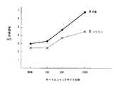
因みに、本発明の発明者が圧接端子1の圧接スロット2に粘度450cpsのシリコンからなる防水剤8を予め付着させたものと、圧接スロット2にポリオールとトリレンジイソシアネートの2液ポリウレタ系RIM(Reaction Injection Molding)樹脂の防水剤8を予め付着させたものを2種類準備し、それぞれの圧接スロット2に電線(0.5sq)Wを圧接接続させた後、−40℃〜+80℃のサーマルショック試験を行い、各圧接ポイント12の接触抵抗を測定してその変化を調べたところ、図14に示すように、防水剤8の種類により差があるが、サーマルショックサイクル数の増加に伴って接触抵抗が増大し、防水圧接コネクタの電気特性に悪影響を及ぼしていることが判明した。 Incidentally, the inventor of the present invention previously attached a
このようなわけで、図12に示す前者の防水圧接コネクタは、圧接端子1の圧接ポイント12に防水剤8が付着し易く、防水圧接コネクタの電気的特性を悪化させる問題がある。 For this reason, the former waterproof pressure contact connector shown in FIG. 12 has a problem that the
一方、図13に示す後者の防水圧接コネクタは、コネクタ本体3におけるハウジング3Aの周縁部の上面が圧接ポイント12より低く形成され、防水突起枠11がカバー4の装着時に防水剤堀溝10に充填された防水剤8中に突入して電線WをU字状に屈曲させて沈め込める構成になっているため、圧接端子1の圧接ポイント12が常時防水剤8中に浸漬されることがなくなる。従って、前者の防水圧接コネクタの問題点がかなり改善される。 On the other hand, in the latter waterproof press contact connector shown in FIG. 13, the upper surface of the peripheral portion of the
しかしながら、防水剤堀溝10に防水剤8を充填させる防水剤充填作業時や圧接端子1の圧接スロット2に電線Wを圧接接続する際必要となる電線位置決め作業時等のコネクタ製造時には、カバー4をコネクタ本体3のハウジング3Aから上方等に退避させるため、防水剤堀溝10と圧接端子1間を遮るものがなく、圧接端子1がコネクタ本体3上で四方に露出状態になる。このため、防水剤充填作業時に防水剤充填治具が圧接端子1に触れたり、電線位置決め作業時に作業手袋が防水剤で汚されたりして、防水剤が圧接ポイントに付着する恐れがある。このため、後者の防水圧接コネクタも電気的特性を悪化させる問題がある。 However, the cover 4 is not used when the connector is manufactured at the time of filling the
本発明の目的は、防水剤充填作業時や電線位置決め作業時等のコネクタ製造時に、防水剤が圧接端子の圧接ポイントに容易に付着することがなく、コネクタの電気的特性を向上させることができる防水圧接コネクタ及びその製造方法を提供することにある。 The object of the present invention is to prevent the waterproofing agent from easily adhering to the press contact point of the press contact terminal during the manufacture of the connector during the waterproofing agent filling operation or the wire positioning operation, and to improve the electrical characteristics of the connector. It is an object of the present invention to provide a waterproof pressure contact connector and a manufacturing method thereof.
上記の目的を達成するために、本発明の請求項1に記載された防水圧接コネクタは、電
線の圧接スロットを有する圧接端子と、圧接端子を収容するハウジング及び圧接端子を保
持する端子保持部が設けられたコネクタ本体と、圧接端子を被うようにコネクタ本体のハ
ウジングに装着されるカバーと、ハウジング内を水密状態に密封する防水剤とを備えた防
水圧接コネクタにおいて、前記カバーが内カバー体と外カバー体とからなり、内カバー体
がハウジングの内部に圧接端子を被うように装着され、外カバー体がハウジングの開口部
側に装着され、内カバー体の装着に伴う押付力で圧接端子の圧接スロットに電線が圧接接
続され、内カバー体と外カバー体との間に防水剤が充填されてなることを特徴とするもの
である。
In order to achieve the above object, a waterproof pressure welding connector according to
本発明の請求項2に記載された防水圧接コネクタは、請求項1記載のものにおいて、前記ハウジングの開口部側に端子保持部側よりも拡径された拡径筒部が設けられ、端子保持部側から拡径筒部に至る境界部分におけるハウジングの内壁面に外側に出っ張る環状の段差部が形成され、前記内カバー体がハウジングの拡径されていない端子保持部側の内部に装着され、前記外カバー体がハウジングの拡径筒部に装着されてなることを特徴とするものである。 According to a second aspect of the present invention, there is provided the waterproof press-connecting connector according to the first aspect, wherein the housing is provided with a diameter-expanding cylindrical portion having a diameter larger than that of the terminal holding portion on the opening side of the housing. An annular stepped portion projecting outward is formed on the inner wall surface of the housing at the boundary portion extending from the portion side to the enlarged diameter cylindrical portion, and the inner cover body is mounted inside the terminal holding portion side where the diameter of the housing is not expanded, The outer cover body is mounted on a diameter-expanded cylindrical portion of the housing.
本発明の請求項3に記載された防水圧接コネクタは、請求項1又は2記載のものにおいて、前記端子保持部に圧接端子を取り囲むように防水剤の侵入を抑制する防水剤侵入抑制枠が設けられてなることを特徴とするものである。 The waterproof press-connecting connector according to
本発明の請求項4に記載された防水圧接コネクタの製造方法は、ベース体の上に請求項1記載のカバーの内カバー体を載置し、内カバー体の上にベース体にまたがるように電線を位置決め配置した後、内カバー体、ベース体及び電線の上に電線屈曲治具を被せて、電線を上に凸になるようにコ字状に屈曲させ、電線屈曲治具を取り外した後、請求項1記載のコネクタ本体を、ハウジングの開口部側が下向きで、圧接端子の圧接スロットが電線に対向するようにして内カバー体、ベース体及び電線の上に被せて押し付け、圧接スロットに電線を圧接接続し、その後、コネクタ本体を上下反転させて内カバー体からベース体を取り外し、又は、内カバー体からベース体を取り外した後、コネクタ本体を上下反転させ、コネクタ本体のハウジングの内部に装着された内カバー体の上に防水剤を充填した後、ハウジングの開口部に外カバー体を装着し、ハウジング内を水密状態に密封することを特徴とするものである。 According to a fourth aspect of the present invention, there is provided a waterproof pressure welding connector manufacturing method comprising: placing the inner cover body of the cover according to the first aspect on a base body, and straddling the base body on the inner cover body. After positioning and arranging the wires, put the wire bending jig on the inner cover body, base body, and wires, bend the wires in a U shape so that they protrude upward, and remove the wire bending jig The connector main body according to
本発明の請求項5に記載された防水圧接コネクタの製造方法は、請求項4記載の製造方法において、前記ベース体が請求項1記載のカバーの外カバー体で構成されることを特徴とするものである。 According to a fifth aspect of the present invention, there is provided a waterproof pressure welding connector manufacturing method according to the fourth aspect of the invention, wherein the base body is constituted by the outer cover body of the cover according to the first aspect. Is.
本発明の請求項1に記載された防水圧接コネクタによると、内カバー体の装着に伴う押付力で圧接端子の圧接スロットに電線が圧接接続された後、内カバー体がハウジングに装着された状態で、内カバー体と外カバー体との間に防水剤が充填されるので、圧接端子の圧接スロットに電線を圧接接続するとき必要な内カバー体に電線を位置決め配置する電線位置決め作業が防水剤充填作業前に行われ、電線位置決め作業時に作業手袋が防水剤で汚されることがなくなる。また、防水剤充填作業時に、内カバー体が仕切り壁の役目をして、防水剤充填治具が圧接端子に触れたり、防水剤が圧接端子側に侵入したりするようなことがなくなる。その結果、防水剤充填作業時や電線位置決め作業時等のコネクタ製造時に、防水剤が圧接端子の電線との接続点である圧接ポイントに付着することがなくなり、防水圧接コネクタの電気的特性を向上させることができる。 According to the waterproof press-connecting connector described in
本発明の請求項2に記載された防水圧接コネクタによると、ハウジングの開口部側に拡
径筒部が設けられて、ハウジングの内壁面に環状の段差部が形成され、内カバー体がハウ
ジングの拡径されていない端子保持部側の内部に装着され、前記外カバー体が拡径筒部に
装着されているので、内カバー体の上面及び外周縁ばかりでなく、ハウジングに環状の段
差部にわたる範囲まで、且つ、内カバー体で電線を保持した状態で防水剤を充填すること
が可能になり、コネクタの防水性をより向上させることができる。更に、防水性能が向上
するので、防水剤の使用量が少なくて済み経済的であり、コネクタを小型にすることがで
きる。
According to the waterproof press-connecting connector described in
本発明の請求項3に記載された防水圧接コネクタによると、前記端子保持部に圧接端子を取り囲むように防水剤の侵入を抑制する防水剤侵入抑制枠が設けられているので、防水剤侵入抑制枠により防水剤が圧接端子側に侵入しにくくなり、圧接端子の圧接ポイントに付着するのが抑制されるので、防水圧接コネクタの電気的特性を更に向上させることができる。 According to the waterproof pressure contact connector according to
本発明の請求項4に記載された防水圧接コネクタの製造方法によると、ベース体の上に内カバー体を載置し、内カバー体の上にベース体にまたがるように電線を位置決め配置し、電線を上に凸になるようにコ字状に屈曲させてから、コネクタ本体をハウジングの開口部側が下向きになるようにして内カバー体、ベース体及び電線の上に被せて押し付けるので、電線を圧接端子の圧接スロットに均等な力で確実に圧入挟持することができる。従って、圧接スロットで電線の被覆が確実に破断されて、圧接スロットに電線を精度よく圧接接続することができ、防水圧接コネクタを容易に能率よく製造することができる。 According to the waterproof pressure welding connector manufacturing method described in claim 4 of the present invention, the inner cover body is placed on the base body, and the electric wires are positioned on the inner cover body so as to straddle the base body. Bend the wire in a U shape so that it protrudes upward, and then press the connector body over the inner cover body, base body, and wire so that the opening side of the housing faces downward. The press-fit terminal can be securely press-fitted into the press-fit slot with an equal force. Therefore, the coating of the electric wire is surely broken at the press-contact slot, and the electric wire can be press-connected to the press-contact slot with high accuracy, and the waterproof press-connect connector can be easily and efficiently manufactured.
本発明の請求項5に記載された防水圧接コネクタの製造方法によると、前記ベース体が外カバー体で構成されるので、ベース体を別に準備しておく必要がなくなり、コネクタの製造コストを低減させることができる。 According to the waterproof pressure welding connector manufacturing method described in claim 5 of the present invention, since the base body is constituted by the outer cover body, it is not necessary to prepare the base body separately, and the manufacturing cost of the connector is reduced. Can be made.
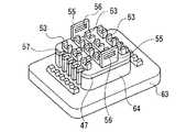
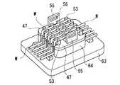
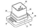
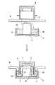
次に、本発明を実施するための最良の形態を図面により詳細に説明する。図1は本発明の防水圧接コネクタの一実施形態を示す断面図、図2はその分解斜視図、図3はそのコネクタにおけるコネクタ本体の端子保持部に圧接端子が保持された状態を示す拡大斜視図、図4はその圧接端子の圧接スロットに電線が圧接接続されている状態を示す拡大部分断面図である。 Next, the best mode for carrying out the present invention will be described in detail with reference to the drawings. 1 is a cross-sectional view showing an embodiment of a waterproof pressure contact connector of the present invention, FIG. 2 is an exploded perspective view thereof, and FIG. 3 is an enlarged perspective view showing a state in which a pressure contact terminal is held by a terminal holding portion of a connector body in the connector. FIG. 4 and FIG. 4 are enlarged partial sectional views showing a state in which the electric wire is press-connected to the press-contact slot of the press-contact terminal.
本実施形態の防水圧接コネクタは、図1乃至4に示すように、例えば、断面円形の電線(絶縁被覆電線)Wが圧入挟持されて被覆W2(図4参照)が破断され、導体W1(図4参照)と圧接接続される電線Wの圧接スロット23を有する良導電性金属材料、例えば、銅材料からなる複数の圧接端子21と、一方側(上方側)にこれら複数の圧接端子21を収容する角筒状の上方に開口するハウジング27及び長手方向のほぼ中央部に圧接端子21を保持する隔壁からなる端子保持部29が設けられたプラスチック成形体からなるコネクタ本体25と、圧接端子21を被うようにコネクタ本体25のハウジング27に装着されるプラスチック製のカバー31と、圧接端子21とカバー31との間に充填されてハウジング27内を水密状態に密封する防水剤33とを備えている。 As shown in FIGS. 1 to 4, the waterproof pressure-welded connector according to the present embodiment has, for example, a press-clamped electric wire (insulation-coated electric wire) W having a circular cross section to break the covering W2 (see FIG. 4), and the conductor W1 (FIG. 4) and a plurality of
複数個の圧接端子21は、例えば、千鳥状に配列され、図3に示すように、各々に上部の電線挿入口が末広がり状に開口する略U、V字状をした1個の圧接スロット23が設けられている。圧接端子21はその各々に1個の圧接スロット23を設ける代わりに、共通1個の圧接端子21に複数の圧接スロット23を形成するようにしてもよく、圧接端子21の構成は本実施形態のものに限定されない。また、端子保持部29に圧接端子21を取り囲むように防水剤33が圧接端子21側に侵入するのを抑制する、例えば、四角形状の防水剤侵入抑制枠35が端子保持部29の上面から起立するように設けられている。この防水剤侵入抑制枠35が設けられていると、これにより防水剤33が圧接端子21側に侵入しにくくなり、圧接端子21の電線Wとの接続点である圧接ポイント37(図4参照)に付着するのが抑制されるので、防水圧接コネクタの電気的特性を更に向上させることができる。 The plurality of
コネクタ本体25のハウジング27の開口部側には、図1、2に示すように、端子保持
部29側よりも拡径された角筒状の拡径筒部39が設けられ、端子保持部29側から拡径
筒部39に至る境界部分におけるハウジング27の内壁面に外側に出っ張る角環状の段差
部41が形成される。
As shown in FIGS. 1 and 2, a rectangular tube-shaped enlarged
また、コネクタ本体25の他方側(下方側)には、図1に示すように、前記ハウジング27と同形状(角筒状)の下方に開口するハウジング43が設けられ、端子保持部29に圧接端子21と一体成形された平型棒状の雄端子45がハウジング43の内部に突出するようにして設けられ、ハウジング43内に挿入される雌コネクタ(図示せず)と接続可能になっている。 Further, as shown in FIG. 1, a
カバー31は、図1、2に示すように、それぞれプラスチック成形に四角形板状に形成
された内カバー体47と外カバー体49とからなる。内カバー体47は上面の両側部付近
に係止用突起51が突設され、下面に複数本の電線Wを案内するための下方に開口する、
例えば、コ字状片からなる複数個の案内部材53が電線Wの配設方向及びこれに垂直な方
向(内カバー体47の幅方向)に所定間隔をおいて突設され、また、下面の両側部付近に
係止用穴56を有する係止用腕55が突設される。更に、電線Wが配設される方向の前後
部に、内カバー体47の装着に伴う押付力でコ字状に屈曲した電線Wを案内する第一の電
線案内溝57aが内カバー体47の幅方向(電線Wの配設方向に垂直な方向)に所定間隔
をおいて複数個設けられる。
As shown in FIGS. 1 and 2, the
For example, a plurality of
A plurality of
なお、コネクタ本体のハウジング27の拡径されていない端子保持部29側の内壁面には、内カバー体47がハウジング27内に装着されたとき、前記内カバー体47の係止用腕55の係止用穴56に係入する2個の係止用爪59が対向するように内方に向けて突設されている。 Note that when the
外カバー体49は下面の両側部付近の前記係止用突起51に対応する部位に、内カバー
体47の係止用突起51が上方に向けて係入する係止用溝61が設けられる。また、電線
Wが配設される方向の前後部にあって、前記内カバー体47の第一の電線案内溝57aに
対応する部位に、同様に電線Wを案内する第二の電線案内溝57bが外カバー体49の幅
方向に所定間隔をおいて複数個設けられる。
The
内カバー体47はハウジング27の拡径されていない端子保持部29側の内部に圧接端子21を被うように装着され、ハウジング27側の係止用爪59が内カバー体47の係止用穴56に係入してハウジング27に係止される。そして、内カバー体47の装着に伴う押付力で圧接端子21の圧接スロット23に電線Wが圧入挟持されて被覆W2が破断され、導体W1と圧接接続される。 The
外カバー体49は、内カバー体47の上に防水剤33を介して、ハウジング27の開口部側の拡径筒部39にその開口部を塞ぐように装着されると共に、その係止用溝61に内カバー体47の係止用突起51が係入して、内カバー体47に係止、固定される。 The
防水剤33は、内カバー体47と外カバー体49との間におけるハウジング27の少な
くとも拡径筒部39内に、防水剤充填治具(図示せず)や手作業により、注入、塗布、貼
付け等することにより所定厚さに充填される。防水剤33は、適度の粘性を有するシリコ
ンやグリス、ホットメルト接着剤、2液混合型硬化弾性樹脂等、内カバー体と外カバー体
との間に充填される前に少なくとも流動性を有するものを使用するのが望ましい。更に、
防水剤33は、外カバー体49を装着した後に充填してもよいが、後記の防水圧接コネク
タの製造方法で説明するように、内カバー体47を装着した後、外カバー体49を装着す
る前に充填する方が充填作業を容易、且つ、能率よく行うことができるので望ましい。本
実施形態の防水圧接コネクタは以上のような構成になっている。
The
The
本発明の防水圧接コネクタによると、内カバー体47の装着に伴う押付力で圧接端子21の圧接スロット23に電線Wが圧接接続された後、内カバー体47がハウジング27に装着された状態で、内カバー体47と外カバー体49との間に防水剤33が充填されるので、圧接端子21の圧接スロット23に電線Wを圧接接続するとき必要な内カバー体47に電線Wを位置決め配置する電線位置決め作業が防水剤充填作業前に行われ、電線位置決め作業時に作業手袋が防水剤33で汚されることがなくなる。また、防水剤充填作業時に、内カバー体47が仕切り壁の役目をして、防水剤充填治具が圧接端子21に触れたり、防水剤33が圧接端子21側に侵入したりするようなことがなくなる。その結果、防水剤充填作業時や電線位置決め作業時等のコネクタ製造時に、防水剤33が圧接端子21の電線Wとの接続点である圧接ポイント37に付着することがなくなり、防水圧接コネクタの電気的特性を向上させることができる。 According to the waterproof press-connecting connector of the present invention, after the electric wire W is press-connected to the press-
また、上記実施形態のように、ハウジング27の開口部側に拡径筒部39が設けられて、ハウジング27の内壁面に環状の段差部41が形成され、内カバー体47がハウジング27の拡径されていない端子保持部29側の内部に装着され、前記外カバー体49が拡径筒部39に装着されていると、内カバー体47の上面及び外周縁ばかりでなく、ハウジング27に環状の段差部41にわたる範囲まで、且つ、内カバー体47で電線Wを保持した状態で防水剤33を充填することが可能になり、コネクタの防水性をより向上させることができる。更に、防水性能が向上するので、防水剤33の使用量が少なくて済み経済的であり、コネクタを小型にすることができる。 Further, as in the above-described embodiment, the enlarged diameter
次に本発明に係る防水圧接コネクタの製造方法(組立方法)の一実施形態を上記防水圧接コネクタを製造する場合について、図5〜11に基づいて説明する。 Next, an embodiment of a method for manufacturing a waterproof pressure welding connector (assembly method) according to the present invention will be described with reference to FIGS.
先ず、図5に示すように、プラスチック成形体で出来た矩形板状のベース体63の中央に形成された台座64に、内カバー体47を載置して着脱自在に固定する。次に、図6に示すように、内カバー体47の上に複数本(図示例は5本)の断面円形の電線Wを案内部材53で案内しながらベース体63にまたがるように位置決め配置した後、図7に示すように、内カバー体47、ベース体63及び電線Wの上に、内側に内カバー体47を挿入し得る角形穴66を有する角形環状の電線屈曲治具65を、その角形穴66に内カバー体47を挿入して嵌合しながら被せて、電線Wを上に凸になるようにコ字状に屈曲させる。 First, as shown in FIG. 5, an
次に、図8に示すように、内カバー体47から電線屈曲治具65を取り外した後、図9に示すように、コネクタ本体25を、ハウジング27の開口部が下向きで、圧接端子21の圧接スロット23が電線Wに対向するようにして、内カバー体47、ベース体63及び電線Wの上に被せて押し付け、圧接スロット23に電線Wを圧入挟持して被覆W2を破断し、導体W1と圧接接続する。 Next, as shown in FIG. 8, after removing the
次に、図10に示すように、コネクタ本体25を上下180度反転させて、内カバー体47をコネクタ本体25のハウジング27内に残した状態で、該内カバー体47からベース体63を取り外した後、図示省略するが、ハウジング27の内部に装着された内カバー体47の上に、防水剤33を注入、塗布、貼付け等により所定厚さに充填する。その後、図11に示すように、ハウジング27の開口部に外カバー体49を装着し、ハウジング27内を水密に密封することにより、防水圧接コネクタの製造を終了する。 Next, as shown in FIG. 10, the
なお、上記製造方法の実施形態では、先にコネクタ本体25を上下反転させてから内カバー体47からベース体63を取り外すようにしたが、先に内カバー体47からベース体63を取り外してからコネクタ本体25を上下反転させるようにしてもよい。 In the embodiment of the manufacturing method, the
本発明に係る防水圧接コネクタの製造方法によると、ベース体63の上に内カバー体47を載置し、内カバー体47の上にベース体63にまたがるように電線Wを位置決め配置し、電線Wを上に凸になるようにコ字状に屈曲させてから、コネクタ本体25をハウジング27の開口部側が下向きになるようにして内カバー体47、ベース体63及び電線Wの上に被せて押し付けるので、電線Wを圧接端子21の圧接スロット23に均等な力で確実に圧入挟持することができる。従って、圧接スロット23で電線Wの被覆W2が確実に破断されて、圧接スロット23に電線Wを精度よく圧接接続することができ、防水圧接コネクタを容易に能率よく製造することができる。 According to the method for manufacturing a waterproof pressure contact connector according to the present invention, the
また、上記製造方法の実施形態では、ベース体63を別に準備したが、外カバー体49をベース体63として使用するようにしてもよい。このようにして防水圧接コネクタを製造すると、ベース体63を予め別個に製作して準備しておく必要がなくなるので、コネクタの製造コストを低減させることができ経済的である。 In the embodiment of the manufacturing method, the
21 圧接端子
23 圧接スロット
25 コネクタ本体
27 ハウジング
29 端子保持部
31 カバー
33 防水剤
35 防水剤侵入抑制枠
37 圧接ポイント
39 拡径筒部
41 段差部
43 ハウジング
45 雄端子
47 内カバー体
49 外カバー体
51 係止用突起
53 案内部材
55 係止用腕
56 係止用穴
57a 第一の電線案内溝
57b 第二の電線案内溝
59 係止用爪
61 係止用溝
63 ベース体
64 台座
65 電線屈曲治具
66 角形穴
W 電線
W1 導体
W2 被覆
21
53 Guide members
55 Locking arm
56 Locking hole
57a First wire guide groove
57b Second
Claims (5)
Translated fromJapaneseを保持する端子保持部が設けられたコネクタ本体と、圧接端子を被うようにコネクタ本体
のハウジングに装着されるカバーと、ハウジング内を水密状態に密封する防水剤とを備え
た防水圧接コネクタにおいて、前記カバーが内カバー体と外カバー体とからなり、内カバ
ー体がハウジングの内部に圧接端子を被うように装着され、外カバー体がハウジングの開
口部側に装着され、内カバー体の装着に伴う押付力で圧接端子の圧接スロットに電線が圧
接接続され、内カバー体と外カバー体との間に防水剤が充填されてなることを特徴とする
防水圧接コネクタ。
A pressure contact terminal having a pressure contact slot for an electric wire, a housing for housing the pressure contact terminal, a connector body provided with a terminal holding portion for holding the pressure contact terminal, and a cover attached to the housing of the connector body so as to cover the pressure contact terminal;, c within Ujingu in waterproof press-connecting connector and a waterproofing agent to seal in a watertight state, the cover consists can the inner cover member and the outer cover member, as the inner cover body to cover the press-connecting terminal in the housing Mounted, the outer cover body is mounted on the opening side of the housing, and the wire is press-connected to the press contact slot of the press contact terminal by the pressing force accompanying the mounting of the inner cover body, and waterproof between the inner cover body and the outer cover body A waterproof pressure-welded connector filled with an agent.
Priority Applications (1)
| Application Number | Priority Date | Filing Date | Title |
|---|---|---|---|
| JP2004054825AJP4391268B2 (en) | 2004-02-27 | 2004-02-27 | Waterproof pressure welding connector and manufacturing method thereof |
Applications Claiming Priority (1)
| Application Number | Priority Date | Filing Date | Title |
|---|---|---|---|
| JP2004054825AJP4391268B2 (en) | 2004-02-27 | 2004-02-27 | Waterproof pressure welding connector and manufacturing method thereof |
Publications (2)
| Publication Number | Publication Date |
|---|---|
| JP2005243563A JP2005243563A (en) | 2005-09-08 |
| JP4391268B2true JP4391268B2 (en) | 2009-12-24 |
Family
ID=35025053
Family Applications (1)
| Application Number | Title | Priority Date | Filing Date |
|---|---|---|---|
| JP2004054825AExpired - Fee RelatedJP4391268B2 (en) | 2004-02-27 | 2004-02-27 | Waterproof pressure welding connector and manufacturing method thereof |
Country Status (1)
| Country | Link |
|---|---|
| JP (1) | JP4391268B2 (en) |
Cited By (15)
| Publication number | Priority date | Publication date | Assignee | Title |
|---|---|---|---|---|
| US9407016B2 (en) | 2012-02-22 | 2016-08-02 | Corning Optical Communications Rf Llc | Coaxial cable connector with integral continuity contacting portion |
| US9484645B2 (en) | 2012-01-05 | 2016-11-01 | Corning Optical Communications Rf Llc | Quick mount connector for a coaxial cable |
| US9525220B1 (en) | 2015-11-25 | 2016-12-20 | Corning Optical Communications LLC | Coaxial cable connector |
| US9548572B2 (en) | 2014-11-03 | 2017-01-17 | Corning Optical Communications LLC | Coaxial cable connector having a coupler and a post with a contacting portion and a shoulder |
| US9548557B2 (en) | 2013-06-26 | 2017-01-17 | Corning Optical Communications LLC | Connector assemblies and methods of manufacture |
| US9590287B2 (en) | 2015-02-20 | 2017-03-07 | Corning Optical Communications Rf Llc | Surge protected coaxial termination |
| US9722363B2 (en) | 2012-10-16 | 2017-08-01 | Corning Optical Communications Rf Llc | Coaxial cable connector with integral RFI protection |
| US9762008B2 (en) | 2013-05-20 | 2017-09-12 | Corning Optical Communications Rf Llc | Coaxial cable connector with integral RFI protection |
| US9859631B2 (en) | 2011-09-15 | 2018-01-02 | Corning Optical Communications Rf Llc | Coaxial cable connector with integral radio frequency interference and grounding shield |
| US9905959B2 (en) | 2010-04-13 | 2018-02-27 | Corning Optical Communication RF LLC | Coaxial connector with inhibited ingress and improved grounding |
| US10033122B2 (en) | 2015-02-20 | 2018-07-24 | Corning Optical Communications Rf Llc | Cable or conduit connector with jacket retention feature |
| US10211547B2 (en) | 2015-09-03 | 2019-02-19 | Corning Optical Communications Rf Llc | Coaxial cable connector |
| US10290958B2 (en) | 2013-04-29 | 2019-05-14 | Corning Optical Communications Rf Llc | Coaxial cable connector with integral RFI protection and biasing ring |
| US10756455B2 (en) | 2005-01-25 | 2020-08-25 | Corning Optical Communications Rf Llc | Electrical connector with grounding member |
| US12034264B2 (en) | 2021-03-31 | 2024-07-09 | Corning Optical Communications Rf Llc | Coaxial cable connector assemblies with outer conductor engagement features and methods for using the same |
Families Citing this family (2)
| Publication number | Priority date | Publication date | Assignee | Title |
|---|---|---|---|---|
| JP6783057B2 (en)* | 2016-02-05 | 2020-11-11 | スリーエム イノベイティブ プロパティズ カンパニー | Connector kit, connector assembly, and connector assembly manufacturing method |
| KR102502611B1 (en)* | 2018-12-28 | 2023-02-23 | 포산 웰링 워셔 모터 매뉴팩처링 컴퍼니 리미티드 | A device having a bushing module and a lead wire |
- 2004
- 2004-02-27JPJP2004054825Apatent/JP4391268B2/ennot_activeExpired - Fee Related
Cited By (22)
| Publication number | Priority date | Publication date | Assignee | Title |
|---|---|---|---|---|
| US10756455B2 (en) | 2005-01-25 | 2020-08-25 | Corning Optical Communications Rf Llc | Electrical connector with grounding member |
| US10312629B2 (en) | 2010-04-13 | 2019-06-04 | Corning Optical Communications Rf Llc | Coaxial connector with inhibited ingress and improved grounding |
| US9905959B2 (en) | 2010-04-13 | 2018-02-27 | Corning Optical Communication RF LLC | Coaxial connector with inhibited ingress and improved grounding |
| US9859631B2 (en) | 2011-09-15 | 2018-01-02 | Corning Optical Communications Rf Llc | Coaxial cable connector with integral radio frequency interference and grounding shield |
| US9768565B2 (en) | 2012-01-05 | 2017-09-19 | Corning Optical Communications Rf Llc | Quick mount connector for a coaxial cable |
| US9484645B2 (en) | 2012-01-05 | 2016-11-01 | Corning Optical Communications Rf Llc | Quick mount connector for a coaxial cable |
| US9407016B2 (en) | 2012-02-22 | 2016-08-02 | Corning Optical Communications Rf Llc | Coaxial cable connector with integral continuity contacting portion |
| US9912105B2 (en) | 2012-10-16 | 2018-03-06 | Corning Optical Communications Rf Llc | Coaxial cable connector with integral RFI protection |
| US9722363B2 (en) | 2012-10-16 | 2017-08-01 | Corning Optical Communications Rf Llc | Coaxial cable connector with integral RFI protection |
| US10236636B2 (en) | 2012-10-16 | 2019-03-19 | Corning Optical Communications Rf Llc | Coaxial cable connector with integral RFI protection |
| US10290958B2 (en) | 2013-04-29 | 2019-05-14 | Corning Optical Communications Rf Llc | Coaxial cable connector with integral RFI protection and biasing ring |
| US9762008B2 (en) | 2013-05-20 | 2017-09-12 | Corning Optical Communications Rf Llc | Coaxial cable connector with integral RFI protection |
| US10396508B2 (en) | 2013-05-20 | 2019-08-27 | Corning Optical Communications Rf Llc | Coaxial cable connector with integral RFI protection |
| US9548557B2 (en) | 2013-06-26 | 2017-01-17 | Corning Optical Communications LLC | Connector assemblies and methods of manufacture |
| US9991651B2 (en) | 2014-11-03 | 2018-06-05 | Corning Optical Communications Rf Llc | Coaxial cable connector with post including radially expanding tabs |
| US9548572B2 (en) | 2014-11-03 | 2017-01-17 | Corning Optical Communications LLC | Coaxial cable connector having a coupler and a post with a contacting portion and a shoulder |
| US9590287B2 (en) | 2015-02-20 | 2017-03-07 | Corning Optical Communications Rf Llc | Surge protected coaxial termination |
| US10033122B2 (en) | 2015-02-20 | 2018-07-24 | Corning Optical Communications Rf Llc | Cable or conduit connector with jacket retention feature |
| US10211547B2 (en) | 2015-09-03 | 2019-02-19 | Corning Optical Communications Rf Llc | Coaxial cable connector |
| US9882320B2 (en) | 2015-11-25 | 2018-01-30 | Corning Optical Communications Rf Llc | Coaxial cable connector |
| US9525220B1 (en) | 2015-11-25 | 2016-12-20 | Corning Optical Communications LLC | Coaxial cable connector |
| US12034264B2 (en) | 2021-03-31 | 2024-07-09 | Corning Optical Communications Rf Llc | Coaxial cable connector assemblies with outer conductor engagement features and methods for using the same |
Also Published As
| Publication number | Publication date |
|---|---|
| JP2005243563A (en) | 2005-09-08 |
Similar Documents
| Publication | Publication Date | Title |
|---|---|---|
| JP4391268B2 (en) | Waterproof pressure welding connector and manufacturing method thereof | |
| KR101352706B1 (en) | Connection member and harness connector | |
| CN106170891B (en) | For connecting the structure of crimp type terminal and electric wire | |
| US8569623B2 (en) | Waterproof joint section forming method and wire harness provided with waterproof joint section formed by the method | |
| JP2006156052A (en) | High voltage electric wire connection structure and high voltage electric wire connection method | |
| JP2013004347A (en) | Shield connector | |
| KR101584453B1 (en) | Waterproof structure of wire harness with connector | |
| JP5995799B2 (en) | Connection structure, connector, and connection method | |
| JPH11312568A (en) | Wire and flat cable connector for electrical connection device for steering | |
| JP4833826B2 (en) | Connection member and harness connection body using the member | |
| JP4219778B2 (en) | Waterproof pressure welding connector | |
| JP2003109702A (en) | Terminal oil-proof water structure | |
| WO2007049724A1 (en) | Connection member and harness connection body using the connection member | |
| JP6182355B2 (en) | Crimp connection structure, connector, and method of manufacturing crimp connection structure | |
| JP2002170627A (en) | Waterproof connector and manufacturing method thereof | |
| JP2018085228A (en) | connector | |
| JPH11329531A (en) | Connector for flat cable | |
| JP2011060426A (en) | Connector | |
| JP4885704B2 (en) | Harness connector | |
| JP2013182759A (en) | Protective cap with crimp terminal and forming method for terminal splice part using protective cap | |
| JP5058876B2 (en) | Connecting parts | |
| JP4153366B2 (en) | IDC connector | |
| JP4381959B2 (en) | Wire harness joint connector and manufacturing method thereof | |
| JP2008166136A (en) | Connection member and harness connection body using the member | |
| JP2025140537A (en) | connector |
Legal Events
| Date | Code | Title | Description |
|---|---|---|---|
| A621 | Written request for application examination | Free format text:JAPANESE INTERMEDIATE CODE: A621 Effective date:20070201 | |
| A977 | Report on retrieval | Free format text:JAPANESE INTERMEDIATE CODE: A971007 Effective date:20090309 | |
| A131 | Notification of reasons for refusal | Free format text:JAPANESE INTERMEDIATE CODE: A131 Effective date:20090324 | |
| A521 | Written amendment | Free format text:JAPANESE INTERMEDIATE CODE: A523 Effective date:20090521 | |
| TRDD | Decision of grant or rejection written | ||
| A01 | Written decision to grant a patent or to grant a registration (utility model) | Free format text:JAPANESE INTERMEDIATE CODE: A01 Effective date:20090908 | |
| A01 | Written decision to grant a patent or to grant a registration (utility model) | Free format text:JAPANESE INTERMEDIATE CODE: A01 | |
| A61 | First payment of annual fees (during grant procedure) | Free format text:JAPANESE INTERMEDIATE CODE: A61 Effective date:20091007 | |
| FPAY | Renewal fee payment (event date is renewal date of database) | Free format text:PAYMENT UNTIL: 20121016 Year of fee payment:3 | |
| R151 | Written notification of patent or utility model registration | Ref document number:4391268 Country of ref document:JP Free format text:JAPANESE INTERMEDIATE CODE: R151 | |
| FPAY | Renewal fee payment (event date is renewal date of database) | Free format text:PAYMENT UNTIL: 20121016 Year of fee payment:3 | |
| FPAY | Renewal fee payment (event date is renewal date of database) | Free format text:PAYMENT UNTIL: 20131016 Year of fee payment:4 | |
| R250 | Receipt of annual fees | Free format text:JAPANESE INTERMEDIATE CODE: R250 | |
| LAPS | Cancellation because of no payment of annual fees |