JP4391141B2 - Separation module and method for producing and using the same - Google Patents
Separation module and method for producing and using the sameDownload PDFInfo
- Publication number
- JP4391141B2 JP4391141B2JP2003178316AJP2003178316AJP4391141B2JP 4391141 B2JP4391141 B2JP 4391141B2JP 2003178316 AJP2003178316 AJP 2003178316AJP 2003178316 AJP2003178316 AJP 2003178316AJP 4391141 B2JP4391141 B2JP 4391141B2
- Authority
- JP
- Japan
- Prior art keywords
- capillary
- ceramic
- separation module
- bundle
- capillaries
- Prior art date
- Legal status (The legal status is an assumption and is not a legal conclusion. Google has not performed a legal analysis and makes no representation as to the accuracy of the status listed.)
- Expired - Fee Related
Links
- 238000000926separation methodMethods0.000titleclaimsdescription39
- 238000004519manufacturing processMethods0.000titleclaimsdescription13
- 239000000919ceramicSubstances0.000claimsdescription56
- 238000000034methodMethods0.000claimsdescription26
- 239000000463materialSubstances0.000claimsdescription24
- 239000012528membraneSubstances0.000claimsdescription24
- 239000010408filmSubstances0.000claimsdescription20
- 239000012466permeateSubstances0.000claimsdescription19
- 238000005266castingMethods0.000claimsdescription18
- 239000011521glassSubstances0.000claimsdescription16
- 229920000642polymerPolymers0.000claimsdescription10
- 238000007789sealingMethods0.000claimsdescription10
- 239000011248coating agentSubstances0.000claimsdescription6
- 238000000576coating methodMethods0.000claimsdescription6
- 239000000853adhesiveSubstances0.000claimsdescription5
- 230000001070adhesive effectEffects0.000claimsdescription5
- 239000000047productSubstances0.000claimsdescription4
- 238000010344co-firingMethods0.000claimsdescription3
- 239000010409thin filmSubstances0.000claimsdescription3
- OKTJSMMVPCPJKN-UHFFFAOYSA-NCarbonChemical compound[C]OKTJSMMVPCPJKN-UHFFFAOYSA-N0.000claimsdescription2
- 230000005540biological transmissionEffects0.000claimsdescription2
- 239000003566sealing materialSubstances0.000claimsdescription2
- 229910001220stainless steelInorganic materials0.000claimsdescription2
- 239000010935stainless steelSubstances0.000claimsdescription2
- 239000000126substanceSubstances0.000claimsdescription2
- 230000000694effectsEffects0.000claims4
- 239000003054catalystSubstances0.000claims2
- 229920001971elastomerPolymers0.000claims1
- 239000000806elastomerSubstances0.000claims1
- 229910002804graphiteInorganic materials0.000claims1
- 239000010439graphiteSubstances0.000claims1
- 239000012510hollow fiberSubstances0.000description17
- PNEYBMLMFCGWSK-UHFFFAOYSA-Naluminium oxideInorganic materials[O-2].[O-2].[O-2].[Al+3].[Al+3]PNEYBMLMFCGWSK-UHFFFAOYSA-N0.000description8
- 238000001035dryingMethods0.000description7
- 239000004033plasticSubstances0.000description7
- 238000001125extrusionMethods0.000description6
- 239000007788liquidSubstances0.000description6
- XLYOFNOQVPJJNP-UHFFFAOYSA-NwaterChemical compoundOXLYOFNOQVPJJNP-UHFFFAOYSA-N0.000description6
- 238000010304firingMethods0.000description5
- 238000010438heat treatmentMethods0.000description5
- 239000000843powderSubstances0.000description5
- 238000004804windingMethods0.000description5
- 229910052602gypsumInorganic materials0.000description4
- 239000010440gypsumSubstances0.000description4
- 238000005304joiningMethods0.000description4
- 239000002184metalSubstances0.000description4
- 229910052751metalInorganic materials0.000description4
- 229920005989resinPolymers0.000description4
- 239000011347resinSubstances0.000description4
- 238000005245sinteringMethods0.000description4
- 239000007787solidSubstances0.000description4
- 125000006850spacer groupChemical group0.000description4
- 239000012141concentrateSubstances0.000description3
- 238000005520cutting processMethods0.000description3
- 238000000465mouldingMethods0.000description3
- 230000001590oxidative effectEffects0.000description3
- CDBYLPFSWZWCQE-UHFFFAOYSA-LSodium CarbonateChemical compound[Na+].[Na+].[O-]C([O-])=OCDBYLPFSWZWCQE-UHFFFAOYSA-L0.000description2
- 239000003795chemical substances by applicationSubstances0.000description2
- 239000003822epoxy resinSubstances0.000description2
- 238000001914filtrationMethods0.000description2
- 238000011010flushing procedureMethods0.000description2
- 239000007789gasSubstances0.000description2
- LNEPOXFFQSENCJ-UHFFFAOYSA-NhaloperidolChemical compoundC1CC(O)(C=2C=CC(Cl)=CC=2)CCN1CCCC(=O)C1=CC=C(F)C=C1LNEPOXFFQSENCJ-UHFFFAOYSA-N0.000description2
- 238000005373pervaporationMethods0.000description2
- 238000005498polishingMethods0.000description2
- 229920000647polyepoxidePolymers0.000description2
- 230000002829reductive effectEffects0.000description2
- 239000012298atmosphereSubstances0.000description1
- 239000011230binding agentSubstances0.000description1
- 230000015572biosynthetic processEffects0.000description1
- 229910052799carbonInorganic materials0.000description1
- 239000001913celluloseSubstances0.000description1
- 229920002678cellulosePolymers0.000description1
- 239000004568cementSubstances0.000description1
- 239000004927claySubstances0.000description1
- 238000004140cleaningMethods0.000description1
- 230000001143conditioned effectEffects0.000description1
- 238000001816coolingMethods0.000description1
- 230000008878couplingEffects0.000description1
- 238000010168coupling processMethods0.000description1
- 238000005859coupling reactionMethods0.000description1
- 238000002425crystallisationMethods0.000description1
- 230000008025crystallizationEffects0.000description1
- 210000003298dental enamelAnatomy0.000description1
- 238000010586diagramMethods0.000description1
- 239000010432diamondSubstances0.000description1
- 229910003460diamondInorganic materials0.000description1
- 239000010433feldsparSubstances0.000description1
- 239000000706filtrateSubstances0.000description1
- 230000004907fluxEffects0.000description1
- 229910021397glassy carbonInorganic materials0.000description1
- 239000001307heliumSubstances0.000description1
- 229910052734heliumInorganic materials0.000description1
- SWQJXJOGLNCZEY-UHFFFAOYSA-Nhelium atomChemical compound[He]SWQJXJOGLNCZEY-UHFFFAOYSA-N0.000description1
- 230000003100immobilizing effectEffects0.000description1
- 238000004898kneadingMethods0.000description1
- 238000003475laminationMethods0.000description1
- 239000010985leatherSubstances0.000description1
- 238000003754machiningMethods0.000description1
- 239000000203mixtureSubstances0.000description1
- 238000001728nano-filtrationMethods0.000description1
- 239000002736nonionic surfactantSubstances0.000description1
- 239000011368organic materialSubstances0.000description1
- 239000002245particleSubstances0.000description1
- 238000005192partitionMethods0.000description1
- 239000011505plasterSubstances0.000description1
- 229920006254polymer filmPolymers0.000description1
- 229910052573porcelainInorganic materials0.000description1
- 239000005373porous glassSubstances0.000description1
- 235000019353potassium silicateNutrition0.000description1
- 238000001556precipitationMethods0.000description1
- 238000003825pressingMethods0.000description1
- 239000010453quartzSubstances0.000description1
- VYPSYNLAJGMNEJ-UHFFFAOYSA-Nsilicon dioxideInorganic materialsO=[Si]=OVYPSYNLAJGMNEJ-UHFFFAOYSA-N0.000description1
- 229910000029sodium carbonateInorganic materials0.000description1
- NTHWMYGWWRZVTN-UHFFFAOYSA-Nsodium silicateChemical compound[Na+].[Na+].[O-][Si]([O-])=ONTHWMYGWWRZVTN-UHFFFAOYSA-N0.000description1
- 239000002904solventSubstances0.000description1
- 238000009987spinningMethods0.000description1
- 230000006641stabilisationEffects0.000description1
- 238000011105stabilizationMethods0.000description1
- 238000009210therapy by ultrasoundMethods0.000description1
- 229920001169thermoplasticPolymers0.000description1
- 239000004416thermosoftening plasticSubstances0.000description1
- 238000003466weldingMethods0.000description1
Images


Classifications
- B—PERFORMING OPERATIONS; TRANSPORTING
- B01—PHYSICAL OR CHEMICAL PROCESSES OR APPARATUS IN GENERAL
- B01D—SEPARATION
- B01D69/00—Semi-permeable membranes for separation processes or apparatus characterised by their form, structure or properties; Manufacturing processes specially adapted therefor
- B01D69/14—Dynamic membranes
- B01D69/141—Heterogeneous membranes, e.g. containing dispersed material; Mixed matrix membranes
- B—PERFORMING OPERATIONS; TRANSPORTING
- B01—PHYSICAL OR CHEMICAL PROCESSES OR APPARATUS IN GENERAL
- B01D—SEPARATION
- B01D61/00—Processes of separation using semi-permeable membranes, e.g. dialysis, osmosis or ultrafiltration; Apparatus, accessories or auxiliary operations specially adapted therefor
- B01D61/36—Pervaporation; Membrane distillation; Liquid permeation
- B01D61/362—Pervaporation
- B—PERFORMING OPERATIONS; TRANSPORTING
- B01—PHYSICAL OR CHEMICAL PROCESSES OR APPARATUS IN GENERAL
- B01D—SEPARATION
- B01D63/00—Apparatus in general for separation processes using semi-permeable membranes
- B01D63/02—Hollow fibre modules
- B01D63/021—Manufacturing thereof
- B01D63/022—Encapsulating hollow fibres
- B01D63/0221—Encapsulating hollow fibres using a mould
- B—PERFORMING OPERATIONS; TRANSPORTING
- B01—PHYSICAL OR CHEMICAL PROCESSES OR APPARATUS IN GENERAL
- B01D—SEPARATION
- B01D63/00—Apparatus in general for separation processes using semi-permeable membranes
- B01D63/02—Hollow fibre modules
- B01D63/021—Manufacturing thereof
- B01D63/0233—Manufacturing thereof forming the bundle
- B—PERFORMING OPERATIONS; TRANSPORTING
- B01—PHYSICAL OR CHEMICAL PROCESSES OR APPARATUS IN GENERAL
- B01D—SEPARATION
- B01D63/00—Apparatus in general for separation processes using semi-permeable membranes
- B01D63/02—Hollow fibre modules
- B01D63/031—Two or more types of hollow fibres within one bundle or within one potting or tube-sheet
- B—PERFORMING OPERATIONS; TRANSPORTING
- B01—PHYSICAL OR CHEMICAL PROCESSES OR APPARATUS IN GENERAL
- B01D—SEPARATION
- B01D63/00—Apparatus in general for separation processes using semi-permeable membranes
- B01D63/06—Tubular membrane modules
- B—PERFORMING OPERATIONS; TRANSPORTING
- B01—PHYSICAL OR CHEMICAL PROCESSES OR APPARATUS IN GENERAL
- B01D—SEPARATION
- B01D63/00—Apparatus in general for separation processes using semi-permeable membranes
- B01D63/06—Tubular membrane modules
- B01D63/061—Manufacturing thereof
- B—PERFORMING OPERATIONS; TRANSPORTING
- B01—PHYSICAL OR CHEMICAL PROCESSES OR APPARATUS IN GENERAL
- B01D—SEPARATION
- B01D63/00—Apparatus in general for separation processes using semi-permeable membranes
- B01D63/06—Tubular membrane modules
- B01D63/062—Tubular membrane modules with membranes on a surface of a support tube
Landscapes
- Chemical & Material Sciences (AREA)
- Chemical Kinetics & Catalysis (AREA)
- Engineering & Computer Science (AREA)
- Manufacturing & Machinery (AREA)
- Water Supply & Treatment (AREA)
- Dispersion Chemistry (AREA)
- Separation Using Semi-Permeable Membranes (AREA)
Description
Translated fromJapanese【0001】
【発明の属する技術分野】
本発明は、キャピラリー状のセラミックフィルタエレメントの束を有している分離モジュール並びにその製造方法及びその使用に関する。
【0002】
【従来の技術】
セラミックフィルタエレメントは非対称構造を有し、その際、薄膜層が、1つ又はそれ以上の中間層で多孔質セラミック支持層に施与されている。多孔質セラミック支持層は外形及び機械的安定度を決定する。常用の実施態様は次のとおりである:
管
管は押出しにより製造される。最も広く使用される寸法は次のとおりである:
1−チャネル管 外径(ED)/内径(ID)=10mm/7mm、
7−チャネル管 ED/チャネル直径(CD)=25mm/7mm、
19−チャネル管 ED/CD=25mm/3.5mm又はそれ以上。
【0003】
工業的に使用されるフィルタエレメントの長さは、1.00mまで、多少の場合に1.20mまでである。
【0004】
ハニカム
薄い壁厚を有する極めて多数のチャネル(丸い又は多角形の)からなっている押し出された物体は、ハニカムと呼ばれる。そのような物体中には、大きな膜面積が、極めて小さな空間中に収容されることができる。しかしながら、チャネルの壁厚は、透過液を外へ除去するには薄すぎる。故に、個々のチャネルは、相互的方法で閉塞され、かつ透過液除去に使用される(EP 0 306 350、EP 0 433 582、EP 0 923 983並びにWO 00/50156)。
【0005】
プレート
プレートは、プレス、注型又は押出しにより製造される。プレートの厚さは数mmである。プレートは、溝をつけて製造されることができる。供給液、濃縮液及び透過液のチャネルは、プレートのスタッキングにより形成される。
【0006】
円板
円板は、フィルムキャスティングにより製造される。フィルムの厚さは0.5mm〜3mmの範囲内である。フィルムポケットは、円板のラミネーションにより、製造されることができる(DE 4 330 163)。
【0007】
キャピラリー
10mm〜約1mmの外径を有するキャピラリーは、押出しにより製造されることができる。比ID/ED=7/10をおおよそ維持することにより、単チャネル管のそれに匹敵しうる高い内圧耐性が、焼成後のキャピラリーの場合に得られる。キャピラリーは堅く、かつ個々に取り扱うことができる。
【0008】
特別な方法は、熱可塑性有機結合剤が使用され、かつ成形が高められた温度で行われる溶融押出である(DE 694 00 874)。
【0009】
中空糸
中空糸という用語は、1mm未満の外径の場合に使用される。これは、軟質プラスチック材料のつぶれを回避するために、押出しの間に、ガスをキャピラリーに流す必要がある(WO 99/22852)。極めて小さな直径は、紡糸により製造されることができる(JP 05/221752、JP 02/091221)。このためには、ポリマーはセラミック粉末で充填され、かつこれは中空糸として紡糸されるか、又はポリマーは溶剤中に溶解され、かつセラミック粉末は懸濁され、かつ沈殿浴中で紡糸される。焼成後に、中空糸は一定の弾性を保持する。これらは、もはや個々のエレメントとして加工されることができない。
【0010】
セラミックフィルタエレメントは、ハウジング中で平行に配置される。結果は、供給液及び排出液(濃縮液)のための結合部及びろ液(透過液)のための結合部及び場合によりフラッシング液(スイープ;sweep)のためのさらなる結合部を有しているモジュールである。多重チャネル管の場合に、膜は、チャネルの内面に施与され、かつろ過は内から外へ達成される。単チャネル管の場合に、キャピラリー及び中空糸は、膜が内側又は外側に施与されている例がある。キャピラリーもしくは中空糸の直径が小さすぎる場合には、内部コーティングはもはや不可能である。
【0011】
モジュール形、特に膜エレメントを固定する方法、流れ条件及び大きさは、支持層の種類及び特別な分離法に依存する。
【0012】
管モジュール中で、管は、個々に組み込まれ、かつシーリングリング又は特別なシーリングキャップ(EP 0 270 051、DE 198 46 041、EP 0 270 051)により、末端部でハウジングにシールされる。管の末端部で金属コネクタが接着結合されるか又ははんだ付けされる方法も記載されている(DE 4 131 407)。キャピラリー及び中空糸の場合に、これは、容認できない複雑な組立をまねくか、又は中空糸の場合のたわみ性のために、少しも可能ではない。相対的に多数のキャピラリー又は中空糸が加工されて束が得られる方法が、ここでは必要とされる。
【0013】
ハニカムを使用しながら、ホール又はスロットが側部に組み込まれているモジュールが記載されており、そのホール又はスロットは、透過液チャネルを開き、かつ透過液の側部排出を可能にする(US 5,855,781、EP 1 060 784)。
【0014】
フィルタポケットは、好ましくは中心ホールを備え、かつ透過液捕集管に通される。これにより、組み合わされてモジュールを形成するスタックが得られる(DE 4 330 163)。
【0015】
これらのモジュールとは異なり、本発明には、セラミックキャピラリーを使用してモジュールが記載されている。次の技術的な解決法はこの分野において公知である:
EP 0 938 921においては、ガラス状炭素膜からなっているキャピラリーの束が、型中に配置され、かつ固体で充填されている樹脂で注型され、その際、樹脂が超音波処理にかけられる。
【0016】
EP 0 841 086には、機械的安定度の達成のために、0.06mm〜3mmの直径を有するフィラメント(ロッド)を中空糸の数に対して0.5倍〜5倍の比で有している中空糸を有するモジュールが記載され、その際、中空糸及びロッドは末端部で多孔板により保持される。US 01/0035374においては、中空糸束は、フィラメントを束の周囲にスパイラルで巻くことによって安定化される。匹敵しうる機械的安定化は、本発明によるセラミックキャピラリーの場合に、必要不可欠ではない。
【0017】
EP 0 941 759には、交換体の製造方法が記載されており、その際には、交換体管の束は、型中に配置され、かつ引き続いてセラミックスリップで充填され、乾燥され、かつ引き続いて焼結されてプレートが得られる。別の段階において、端部プレートは同じようにして形成される。供給及び排出のための捕集管は、第一のプレート及び端部プレート中へ、管に平行に組み込まれる。そのような配置が膜モジュールに使用されることができ、その際、キャピラリーが使用されず、かつ管の間の応用に特別な距離が確立されないことが挙げられる。
【0018】
DE 4 133 250には、膜管束の製造方法の特許の保護が請求されており、その際には、膜管の間の均一距離が、末端部を広げて正多角形を形成し、かつ接着結合もしくは溶接による物質を不透過にして結合させることにより確立される。それとは異なって、本発明におけるキャピラリーは、末端部で広げられていない。
【0019】
EP 0 092 839においては、無孔性端部プレートが使用され、そのプレートを貫いてホールが孔あけされており、その中で多孔質管が特別な接合部を用いて固定されている。固定は、ほうろう、ガラス、セラミック、炭素、セメント又は金属により達成される。WO 01/87469においては、完全セラミックモジュールは、セラミック支持層を多孔端板と円筒形外部ケーシングとからなるハウジングに接合することにより組み立てられている。これら全ての場合に、多孔板は、管もしくはキャピラリーの機械的固定に利用される。管は固定距離を有するが、しかしこれは、分離法と、特に透過液量と関係していない。
【0020】
JP 61/004509においては、多孔質ガラス膜管の末端部をシールするために適合された膨張係数を有する、ガラス粉末及びセラミック粉末の混合物の水性スリップが使用される。JP 57166244には、小さな管をシーリング材料、例えばガラスでシーリングすることが記載され、その結果、気密な端板が形成する。双方の場合に、キャピラリーの末端部のシーリング及び機械的固定が達成される。しかしながら、応用に関連した、定義された距離が確立されない。
【0021】
US 4,296,052、US 4,224,386及びUS 4,219,613には、中空糸バッテリー用の多孔板の製造が記載され、前記多孔板は上部のヘリウム密な領域及びその下にある多孔質領域からなり、かつそこを多数の無機の中空糸が通る。中空糸壁は、隔壁として利用され、そこを通って物質輸送は行われず、かつそれゆえ、さらに中空糸間の定義された距離も不必要である。
【0022】
【特許文献1】
EP 0 306 350
【特許文献2】
EP 0 433 582
【特許文献3】
EP 0 923 983
【特許文献4】
WO 00/50156
【特許文献5】
DE 4 330 163
【特許文献6】
DE 694 00 874
【特許文献7】
WO 99/22852
【特許文献8】
JP 05/221752
【特許文献9】
JP 02/091221
【特許文献10】
EP 0 270 051
【特許文献11】
DE 198 46 041
【特許文献12】
DE 4 131 407
【特許文献13】
US 5,855,781
【特許文献14】
EP 1 060 784
【特許文献15】
EP 0 938 921
【特許文献16】
EP 0 841 086
【特許文献17】
US 01/0035374
【特許文献18】
EP 0 941 759
【特許文献19】
DE 4 133 250
【特許文献20】
EP 0 092 839
【特許文献21】
WO 01/87469
【特許文献22】
JP 61/004509
【特許文献23】
JP 57166244
【特許文献24】
US 4,296,052
【特許文献25】
US 4,224,386
【特許文献26】
US 4,219,613
【0023】
【発明が解決しようとする課題】
本発明の課題は、特別な応用のパラメーターに基づく最適な空間利用を有する分離モジュールの場合に、先行技術の記載された欠点を排除することである。
【0024】
【課題を解決するための手段】
この課題は、特許請求の範囲に記載された本発明により解決される。
【0025】
本発明は、実施態様に基づいてより詳細に説明される。
【0026】
本発明は、セラミックキャピラリーの少なくとも1つの束を有している分離モジュールを記載するものであり、その際には、距離はキャピラリー管の間で接合により確立され、このことは、本発明に本質的である。距離の選択は、妨害なしに流出すべきである透過液体積に依存する。透過液体積は次には、本発明による生成物についての次の例1及び2に関連して説明されているように、膜の種類及びそれと結びついた使用方法により決定される。
【0027】
【実施例】
例1
長さ1m、外径1mm及び内径0.7mmを有するキャピラリーを使用する場合には、キャピラリー100本の束は0.2m2の膜面積を有する。ナノろ過膜の流量は、20barで約400 l/(m2・h)である。毎時80 lが記載された束から発生する。束の外部ケーシングは、透過液の流出のために長さ1mを有するスロット約40個を含んでいた。透過液の全量が束の内部から発生したと仮定した場合に、スロット当たり2 l/hが発生する。0.01mmのスロット幅は、問題なく支配されることができる0.05m/sの透過液流速となった。
【0028】
例2
同じキャピラリー束が、透過気化(pervaporation)において考慮される場合には、25kg H2O/m2までの流量を膜の場合に予期しなければならない。100℃及び1barで、水蒸気は1.694m3/kgの密度を有する。0.2m2の面積を有する前記のキャピラリー束は、8.47m3/hの透過液体積となり、これは、透過液側で約20mbarの低下した圧力の結果として335m3/hに増大した。スロット当たり蒸気8.38m3/hが除去される。例1と同じスロット幅で、蒸気は232.5m/sで流れた。常用の流速及び管は、20mbarで25m/s〜50m/sである。これは0.1mmのスロット幅に相当した。透過液側の圧力損失をできるだけ小さく保持するために、2m/s〜5m/sのより低い流速が予期されるべきであり、このことは、1mmのスリット幅に相当した。
【0029】
次に、本発明による製造方法の3つの変法は、まず最初に原則として、かつついで例3〜5に基づいて、詳細に説明される:
キャピラリーは、押出しにより製造され、かつ0.3mm〜10mm、好ましくは1mm〜2.5mmの外径及び0.3mm〜8mm、好ましくは0.7mm〜1.5mmの内径を有する。
【0030】
キャピラリー束の製造は、第一の変法において、ポリマー含有、セラミック含有及び/又はガラス含有の注型材料で末端部をシールすることにより達成される。このためには、キャピラリーは、キャピラリーを底部で固定するために定義されたホール距離を有するホールを有しているビーカー状の型中に末端部で配置される。ビーカーは注型材料で充填される。注型材料は、キャピラリーを完全に囲み、かつ空気中及び室温で、ビーカーが除去できるようなほどに乾燥する。ポリマー注型材料の場合に、硬化は、例えば、エポキシ樹脂の場合には、室温で硬化剤を添加しながらか、又は一成分樹脂の場合にはいくらか高められた温度で達成されることができる。セラミック含有及び/又はガラス含有の注型材料を使用しながら、硬化は150℃〜1600℃の温度で熱的に行われる。手順は、キャピラリー束の両末端部で同時にか又は連続して実施される。同時に実施される場合には、空気中での短い乾燥後に寸法安定である注型材料が使用される。束の末端部の切り離し又は研磨により、シーリングの際に部分的に閉じたチャネルが、再び開く。
【0031】
この変法において、本発明による定義された距離は、型の底板中のホールパターン及び成形品の全収縮により確立され、かつ0.05mm〜10mmの範囲内で変動することができ、かつ膜の予期された流量値に相応して選択されることができる。
【0032】
第二の変法において、距離は、多孔板を使用しながら定義された方法で確立される。多孔板は、異なる材料、例えばプラスチック、金属又はセラミックからなっていてよい。多孔板のホールは、キャピラリーの直径よりも直径が僅かに大きい。キャピラリーは、多孔板のホール中へ挿入される。
【0033】
プラスチック、金属又は焼結されたセラミックからなる多孔板の場合に、接合は、ポリマー含有、セラミック含有又はガラス含有のスリップ、ペースト又は接着剤を使用しながら達成される。このためには、多孔板は、接合材料中へ完全にか又は部分的に浸漬されるか、又は接合材料は、ホール壁とキャピラリーの外側との間のキャビティ中へ導入される。まず最初に、乾燥は室温で空気中で実施される。ポリマー注型材料の場合に、硬化は、例えば、エポキシ樹脂の場合に室温で硬化剤を添加しながらか、又は一成分樹脂の場合にいくらか高められた温度で達成される。セラミック含有及び/又はガラス含有の注型材料を使用しながら、硬化は150℃〜1600℃の温度で熱的に行われる。手順は、キャピラリー束の両末端部で同時にか又は連続して実施される。同時に実施される場合には、空気中の短い乾燥後に寸法安定であるペースト状接合材料が使用される。
【0034】
キャピラリー束の製造のためには、未焼結のセラミック多孔板も使用されることができる。このためには、セラミックキャピラリーは多孔板中へ挿入される。引き続いて、多孔板の焼結温度での熱処理が達成され、その際、前記多孔板は、その収縮の結果、キャピラリー上で収縮するので、機械的に安定でかつ緊密な結合が形成する。
【0035】
未焼結のセラミックキャピラリーを未焼結のセラミック多孔板中へ挿入し、かつ引き続いて双方とも一緒に焼成する(同時焼成)ことも可能である。
【0036】
接合がキャピラリーのチャネルの閉塞をまねく場合には、これらは、束の末端部の切り離し又は研磨により再び開かれる。定義された距離は、この場合に、多孔板中のホールパターンにより確立され、かつ0.1mm〜10mmの範囲内で変動されることができ、かつ膜の予期された流量値に相応して選択されることができる。
【0037】
第三の変法において、定義された距離は、セラミックキャピラリー間で、キャピラリーを硬化性材料のストリップ状フィルムで巻くことにより確立される。
【0038】
ポリマーフィルムの場合に、硬化は、いくらか高められた温度で達成される。セラミック含有及び/又はガラス含有のフィルムを使用しながら、硬化は、150℃〜1600℃で熱的に達成される。手順は、キャピラリー束の両末端部で同時に実施される。キャピラリー束の末端部に加えて、ストリップは、束の長さに亘り一定の間隔で同時に巻かれてよく、そのストリップは、硬化後に、固定された緊密なスペーサーとして作用する。巻きのアルゴリズムの変化により、じゃま板に類似して強制流れとなる円形のスペーサー中で狭いセカント状の切り抜きを確立することができる。
【0039】
巻きは、未焼結のセラミックキャピラリー及び未焼結のセラミックフィルムを用いても達成されることができる。この場合に、固定されかつ緊密な結合は1700℃までの温度での同時焼成により達成される。
【0040】
定義された距離は、この場合に、接合フィルムの厚さ及び巻きアルゴリズムにより決定され、かつ0.1mm〜1mmの範囲内で変動されることができ、かつ膜の予期された流量値に相応して選択されることができる。
【0041】
これらの接合プロセスは、典型的には、10mm〜250mm、好ましくは20mm〜50mmの直径を有するキャピラリー束をもたらす。束中のキャピラリーの距離は≦3mmである。モジュール中には、こうして製造されたこれらの複数のキャピラリー束が好ましくは平行に配置される。ハウジングは、ステンレス鋼からなっていてよく、かつ供給空間及び透過空間のシーリングは、エラストマーO−リングにより達成されることができる。
【0042】
化学的及び熱的な耐性への最も高い要求に適合するために、ハウジングはセラミックから製造される。ハウジング部材の成形は、ついで、注型を用いるか及び/又はレザーハード状態(leather-hard state)でのセラミックブランクの機械的加工により達成される。供給空間及び透過空間の同時の分離を伴うハウジング及びキャピラリー束の結合は、焼結されたハウジング部材の場合に、セラミック含有又はガラス含有のスリップ、ペースト又は接着剤で接合し、引き続いて500℃〜1400℃の温度で熱処理することにより達成される。
【0043】
液体ろ過、ガス分離又は透過気化における分離モジュールの応用のためには、多孔質セラミックキャピラリー上に膜層が必要不可欠である。膜層は、原則的に、キャピラリーの内面並びにその外面の双方に存在していてよい。膜層は、スリップコーティング、ゾル−ゲル技術又は溶液からの結晶化の多様な方法により製造される。全ての場合に、>300℃の温度での膜層の熱処理(焼成)が続く。プラスチック含有の注型材料、プラスチックからなる多孔板又は接合フィルムを使用しながら、そのように高い温度でのキャピラリー束の熱処理は不可能である。この場合に、膜は、接合する前にキャピラリー束に施与される。しかしながら、完全セラミックキャピラリー束もしくはモジュールである場合には、コーティングは、キャピラリー束もしくはモジュールの完成後に少なくとも部分的に達成される。
【0044】
例3
注型材料でのキャピラリー束の接合(図3)
外径3.6mm及び内径2.0mmを有し、アルミナ99.8%を有している焼結された多孔質キャピラリー9を、長さ350mmに切断する。注型材料のためには、高アルミナ含有磁器スリップが製造され、その主成分は粘土52%、石英11%、長石13%、アルミナ26%、水31%(固体に基づく)、水ガラス0.5%(固体に基づく)及び炭酸ナトリウム0.2%(固体に基づく)である。注型に使用された型8は成形用プラスターからなる。直径3.6mm及び深さ8mmを有するホール19個が型の底部に存在する(図3a)。型の内径は27mmである。キャピラリー9は、型の底部でホール中へ挿入され(図3b)、かつドラムミル中でバッチ仕様書に相応して製造されたスリップ10は、手動でかつ連続的に型中に導入される(図3c)。未焼成の端板11の成形品の取り出しは、レザーハード状態で12〜15%の残留含水量で可能である(図3d)。2%の残留含水量までの白乾燥(white drying)が続く。キャピラリー束の第二の側の接合は同じようにして達成される。引き続いて、乾燥させたキャピラリー束ブランク上の端面で突き出たキャピラリーを、ダイヤモンドカッティングホイールを用いて切り離し、かつ端面を清浄にする(図3e)。引き続く焼成サイクルは次の段階からなる:1)加熱段階、2)酸化的清浄化段階、3)還元的硬焼成段階、4)酸化的冷却段階。束の焼結は、1470℃の焼結温度及び45minの保持時間で横方向で達成される。焼結された端板12を有する束のその後の加工は不必要である(図3f)。
【0045】
例4
多孔板を有するキャピラリー束(図4〜6)
外径2.9mm及び内径2.0mmを有し、アルミナ99.8%を有している焼結された多孔質キャピラリーを、長さ320mmに切断する。キャピラリー束の末端部での多孔板(図4)は緻密なアルミナからなる。これらは、32mmの外径を有し、かつホール55個は、セグメント中に均一に配置され、かつ直径2.9mmを有する。双方の材料は、(7.6〜7.8)・10-6K-1の線形熱膨張係数を有する。多孔板の製造には、0.8μmの平均粒度を有し、MgOがドープされたアルミナ粉末を、難可塑性の(stiff-plastic)形で押し出す。アルミナの可塑化のために、後者を、水溶性セルロース5%、非イオン界面活性剤3%、ろう2%及び水10%と一緒に二軸スクリュー混練機中で導入する。約2hの混練時間後、難可塑性材料を、真空−スクリュー押出機中で、750mmの長さを有する多孔押出物として押し出す。多孔押出物用の金型は、その内径が35.5mmであるスリーブ及びその直径が3.2mmであるピン55個からなる。成形品の乾燥は、状態調節した戸棚中で達成され、その際、28℃及び湿度100%で開始する。この時点で、成形品の含水量はまだ10%である。72時間後、乾燥は完了する。ブランクの含水量は2%である。乾燥させたブランクを、10mmの長さに切断し、かつキャピラリー55本を、キャピラリーの末端部がその都度多孔板の端面と共にフラッシングされる多孔板2枚中へ挿入する(図5)。この位置で末端部は有機接着剤を用いて固定される。80℃で2時間乾燥後に、キャピラリー束ブランクは、1580℃で酸化的雰囲気下に横方向で焼結させる。焼結過程の間に、全有機材料は燃え尽き、かつ多孔板はキャピラリー上で収縮する。強い結合が形成する。最終的には、多孔板の端面を、ガラスを用いて気密にシールする。図6は、キャピラリー間の流れを制御するためのスペーサーを有する実施態様を示す。
【0046】
例5
フィルムストリップで巻かれたキャピラリー束(図7及び8)
外径1.4mm及び内径1.0mmを有し、アルミナ99.8を有している焼結された多孔質キャピラリー9を、長さ350mmに切断する。これらの切断した部分を、図7に表されているように、平行に軟質セラミックフィルムストリップ13中へプレスする。これらのセラミックフィルムストリップ13は2mmの厚さを有する。引き続いて、キャピラリー9及びストリップ13の組合せを、図8に表されているように、束中へ巻く。フィルムストリップ13の食い違った取り付けの結果として、じゃま板6により分離され、かつ正確に定義された大きさを有する室がキャピラリー9間に形成するので、蛇行した流れは、引き続きモジュールを通り行われる。例3に類似に実施される末端部のシーリングは、別の加工段階として続き、その際、型の底部を不要にすることを可能にする、それというのも、束のキャピラリーは、ストリップにより正しい距離に保持されるからである。
【図面の簡単な説明】
【図1】a)内部コーティング及びb)外部コーティングに関する支持層(T)、中間層(ZS)及び膜(M)を有している管形のフィルタエレメントの基本的な非対称構造を示す略示図。
【図2】供給液(1)、濃縮液(2)、透過液(3)及びスイープ(4)のための結合部並びにフィルタエレメント(5)、強制流れを生じさせるためのじゃま板(6)及びハウジング(7)を有している分離モジュールの略示図。
【図3】注型材料を用いて接合する原理(請求項14):a)セッコウ型(8)、b)キャピラリー(9)を有するセッコウ型(8)、c)キャピラリー(9)及び導入された注型用スリップ(10)を有するセッコウ型(8)、d)未焼結の端板(11)を有するキャピラリー束、e)未焼結の端板(11)を有するトリミングされたキャピラリー束、f)焼結された端板(12)を有するキャピラリー束を示す略示図。
【図4】多孔円板(請求項15〜17)を示す略示図。
【図5】請求項15から17までのいずれか1項に従って製造された分離モジュールを示す略示図。
【図6】請求項8記載のスペーサーを有している請求項15から17までのいずれか1項に従って製造された分離モジュールを示す略示図。
【図7】フィルムストリップ中へプレスされたキャピラリー(請求項19)を示す略示図:a)平面図、b)側面図。
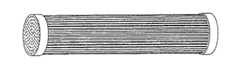
【図8】巻いた後のキャピラリー束の断面の略示図(請求項8、18及び19)。
【符号の説明】
1 供給液、 2 濃縮液、 3 透過液、 4 スイープ(フラッシング液)、 5 フィルタエレメント、 6 じゃま板、 7 ハウジング、 8 セッコウ型、 9 キャピラリー、 10 注型用スリップ、 11 未焼結の端板、 12 焼結された端板、 13 フィルムストリップ[0001]
BACKGROUND OF THE INVENTION
The present invention relates to a separation module having a bundle of capillary ceramic filter elements, a method for producing the same, and a use thereof.
[0002]
[Prior art]
The ceramic filter element has an asymmetric structure, in which a thin film layer is applied to the porous ceramic support layer with one or more intermediate layers. The porous ceramic support layer determines the profile and mechanical stability. Common embodiments are as follows:
Tubes are manufactured by extrusion. The most widely used dimensions are:
1-channel tube outer diameter (ED) / inner diameter (ID) = 10 mm / 7 mm,
7-channel tube ED / channel diameter (CD) = 25 mm / 7 mm,
19-channel tube ED / CD = 25 mm / 3.5 mm or more.
[0003]
The length of industrially used filter elements is up to 1.00 m and in some cases up to 1.20 m.
[0004]
An extruded object consisting of a very large number of channels (round or polygonal) with a honeycomb thin wall thickness is called a honeycomb. In such an object, a large membrane area can be accommodated in a very small space. However, the channel wall thickness is too thin to remove permeate out. Thus, the individual channels are closed in a reciprocal manner and used for permeate removal (EP 0 306 350, EP 0 433 582, EP 0 923 983 and WO 00/50156).
[0005]
The plate plate is manufactured by pressing, casting or extrusion. The thickness of the plate is a few mm. The plate can be manufactured with grooves. Feed, concentrate and permeate channels are formed by stacking the plates.
[0006]
Discs Discs are manufactured by film casting. The thickness of the film is in the range of 0.5 mm to 3 mm. Film pockets can be manufactured by disc lamination (DE 4 330 163).
[0007]
Capillaries having an outer diameter of 10 mm to about 1 mm can be produced by extrusion. By roughly maintaining the ratio ID / ED = 7/10, high internal pressure resistance comparable to that of a single channel tube is obtained in the case of capillaries after firing. Capillaries are stiff and can be handled individually.
[0008]
A special method is melt extrusion in which a thermoplastic organic binder is used and the molding takes place at an elevated temperature (DE 694 00 874).
[0009]
The term hollow fiber hollow fiber is used when the outer diameter is less than 1 mm. This requires gas to flow through the capillary during extrusion to avoid collapse of the soft plastic material (WO 99/22852). Very small diameters can be produced by spinning (JP 05/221752, JP 02/091221). For this purpose, the polymer is filled with ceramic powder and this is spun as a hollow fiber, or the polymer is dissolved in a solvent and the ceramic powder is suspended and spun in a precipitation bath. After firing, the hollow fiber retains a certain elasticity. They can no longer be processed as individual elements.
[0010]
The ceramic filter elements are arranged in parallel in the housing. The result has a joint for the feed and drain (concentrate) and a joint for the filtrate (permeate) and possibly a further joint for the flushing liquid (sweep). It is a module. In the case of a multichannel tube, the membrane is applied to the inner surface of the channel and filtration is accomplished from inside to outside. In the case of a single channel tube, there are examples in which the capillaries and hollow fibers have membranes applied inside or outside. If the capillary or hollow fiber diameter is too small, inner coating is no longer possible.
[0011]
The modular form, in particular the method of fixing the membrane element, the flow conditions and the size, depends on the type of support layer and the specific separation method.
[0012]
In the tube module, the tubes are individually assembled and sealed to the housing at the end by means of sealing rings or special sealing caps (EP 0 270 051, DE 198 46 041, EP 0 270 051). A method is also described in which a metal connector is adhesively bonded or soldered at the end of the tube (DE 4 131 407). In the case of capillaries and hollow fibers, this leads to unacceptably complex assembly, or is not possible at all due to the flexibility in the case of hollow fibers. What is needed here is a method in which a relatively large number of capillaries or hollow fibers are processed to obtain a bundle.
[0013]
While using a honeycomb, a module is described in which holes or slots are incorporated in the sides, which holes or slots open the permeate channel and allow the permeate to be discharged side-by-side (US 5,855,781). , EP 1 060 784).
[0014]
The filter pocket preferably comprises a central hole and is passed through the permeate collection tube. This gives a stack that is combined to form a module (DE 4 330 163).
[0015]
Unlike these modules, the present invention describes modules using ceramic capillaries. The following technical solutions are known in the art:
In EP 0 938 921, a bundle of capillaries made of a glassy carbon film is cast with a resin placed in a mold and filled with a solid, and the resin is then subjected to ultrasonic treatment.
[0016]
EP 0 841 086 has filaments (rods) having a diameter of 0.06 mm to 3 mm in a ratio of 0.5 to 5 times the number of hollow fibers in order to achieve mechanical stability. A module having a hollow fiber is described, wherein the hollow fiber and the rod are held at the end by a perforated plate. In US 01/0035374, a hollow fiber bundle is stabilized by spirally winding a filament around the bundle. Comparable mechanical stabilization is not essential in the case of the ceramic capillaries according to the invention.
[0017]
EP 0 941 759 describes a method of manufacturing an exchanger, in which a bundle of exchanger tubes is placed in a mold and subsequently filled with ceramic slip, dried and subsequently And sintered to obtain a plate. In another stage, the end plate is formed in the same way. Collection tubes for supply and discharge are incorporated into the first plate and end plate in parallel with the tube. Such an arrangement can be used for the membrane module, in which no capillaries are used and no special distance is established for the application between the tubes.
[0018]
DE 4 133 250 claims a patent protection method for the production of membrane tube bundles, in which case the uniform distance between the membrane tubes widens the end to form a regular polygon and adheres to it. Established by immobilizing and bonding materials by bonding or welding. In contrast, the capillaries in the present invention are not widened at the ends.
[0019]
In EP 0 092 839, a non-porous end plate is used, holes are drilled through the plate, in which a porous tube is fixed with a special joint. Fixing is achieved with enamel, glass, ceramic, carbon, cement or metal. In WO 01/87469, a complete ceramic module is assembled by joining a ceramic support layer to a housing consisting of a porous end plate and a cylindrical outer casing. In all these cases, perforated plates are used for mechanical fixation of tubes or capillaries. The tube has a fixed distance, but this is not related to the separation method and in particular to the permeate volume.
[0020]
In JP 61/004509, an aqueous slip of a mixture of glass powder and ceramic powder with an expansion coefficient adapted to seal the end of a porous glass membrane tube is used. JP 57166244 describes sealing small tubes with a sealing material, such as glass, resulting in the formation of an airtight end plate. In both cases, sealing and mechanical fixing of the end of the capillary is achieved. However, no defined distance associated with the application is established.
[0021]
US 4,296,052, US 4,224,386 and US 4,219,613 describe the manufacture of perforated plates for hollow fiber batteries, said perforated plate comprising an upper helium dense region and a porous region below it, and a number of them. An inorganic hollow fiber passes. The hollow fiber wall is used as a partition, through which no mass transport takes place, and therefore a defined distance between the hollow fibers is also unnecessary.
[0022]
[Patent Document 1]
EP 0 306 350
[Patent Document 2]
EP 0 433 582
[Patent Document 3]
EP 0 923 983
[Patent Document 4]
WO 00/50156
[Patent Document 5]
DE 4 330 163
[Patent Document 6]
DE 694 00 874
[Patent Document 7]
WO 99/22852
[Patent Document 8]
JP 05/221752
[Patent Document 9]
JP 02/091221
[Patent Document 10]
EP 0 270 051
[Patent Document 11]
DE 198 46 041
[Patent Document 12]
DE 4 131 407
[Patent Document 13]
US 5,855,781
[Patent Document 14]
EP 1 060 784
[Patent Document 15]
EP 0 938 921
[Patent Document 16]
EP 0 841 086
[Patent Document 17]
US 01/0035374
[Patent Document 18]
EP 0 941 759
[Patent Document 19]
DE 4 133 250
[Patent Document 20]
EP 0 092 839
[Patent Document 21]
WO 01/87469
[Patent Document 22]
JP 61/004509
[Patent Document 23]
JP 57166244
[Patent Document 24]
US 4,296,052
[Patent Document 25]
US 4,224,386
[Patent Document 26]
US 4,219,613
[0023]
[Problems to be solved by the invention]
The object of the present invention is to eliminate the described drawbacks of the prior art in the case of separation modules with optimal space utilization based on the parameters of the particular application.
[0024]
[Means for Solving the Problems]
This problem is solved by the present invention described in the claims.
[0025]
The invention is explained in more detail on the basis of embodiments.
[0026]
The present invention describes a separation module having at least one bundle of ceramic capillaries, wherein the distance is established by bonding between the capillary tubes, which is essential to the present invention. Is. The choice of distance depends on the permeate volume that should flow out without interference. The permeate volume is then determined by the type of membrane and the associated method of use, as described in connection with the following examples 1 and 2 for the products according to the invention.
[0027]
【Example】
Example 1
When a capillary having a length of 1 m, an outer diameter of 1 mm and an inner diameter of 0.7 mm is used, a bundle of 100 capillaries has a membrane area of 0.2 m2 . The flow rate of the nanofiltration membrane is about 400 l / (m2 · h) at20 bar. 80 l per hour is generated from the bundle described. The outer casing of the bundle contained about 40 slots having a length of 1 m for the permeate outflow. Assuming that the total amount of permeate is generated from inside the bundle, 2 l / h is generated per slot. A slot width of 0.01 mm resulted in a permeate flow rate of 0.05 m / s that could be controlled without problems.
[0028]
Example 2
If the same capillary bundle is considered in pervaporation, flow rates up to 25 kg H2 O / m2 must be expected for the membrane. At 100 ° C. and 1 bar, the water vapor has a density of 1.694 m3 / kg. Capillary flux with having an area of 0.2 m2 becomes a permeate volume of 8.47m3 / h, which was increased to 335m3 / h as a result of reduced pressure of about 20mbar at the permeate side. Steam 8.38 m3 / h per slot is removed. With the same slot width as in Example 1, the steam flowed at 232.5 m / s. Conventional flow rates and tubes are 25 m / s to 50 m / s at 20 mbar. This corresponded to a slot width of 0.1 mm. In order to keep the pressure loss on the permeate side as small as possible, a lower flow rate of 2 m / s to 5 m / s should be expected, which corresponded to a slit width of 1 mm.
[0029]
Next, the three variants of the production process according to the invention are explained in detail first, in principle, and then on the basis of Examples 3-5:
The capillaries are manufactured by extrusion and have an outer diameter of 0.3 mm to 10 mm, preferably 1 mm to 2.5 mm and an inner diameter of 0.3 mm to 8 mm, preferably 0.7 mm to 1.5 mm.
[0030]
The manufacture of capillary bundles is achieved in a first variant by sealing the end with a polymer-containing, ceramic-containing and / or glass-containing casting material. For this purpose, the capillaries are arranged at the end in a beaker-shaped mold having holes with a defined hole distance for fixing the capillaries at the bottom. The beaker is filled with casting material. The casting material completely dries the capillary so that the beaker can be removed in air and at room temperature. In the case of polymer casting materials, curing can be achieved, for example, in the case of epoxy resins, with the addition of a curing agent at room temperature, or in the case of monocomponent resins at somewhat elevated temperatures. . Curing is done thermally at temperatures between 150 ° C. and 1600 ° C. while using ceramic and / or glass containing casting materials. The procedure is performed simultaneously or sequentially at both ends of the capillary bundle. When carried out simultaneously, a casting material is used that is dimensionally stable after short drying in air. Cutting or polishing the end of the bundle reopens the partially closed channel during sealing.
[0031]
In this variant, the defined distance according to the invention is established by the hole pattern in the mold bottom plate and the total shrinkage of the molded part and can vary within the range of 0.05 mm to 10 mm and It can be selected according to the expected flow value.
[0032]
In the second variant, the distance is established in a defined way using a perforated plate. The perforated plate may be made of different materials, such as plastic, metal or ceramic. The hole in the perforated plate is slightly larger in diameter than the capillary. The capillary is inserted into the hole in the perforated plate.
[0033]
In the case of perforated plates made of plastic, metal or sintered ceramic, bonding is achieved using polymer-containing, ceramic-containing or glass-containing slips, pastes or adhesives. For this purpose, the perforated plate is completely or partially immersed in the bonding material, or the bonding material is introduced into the cavity between the hole wall and the outside of the capillary. First, drying is performed in air at room temperature. In the case of polymer casting materials, curing is achieved, for example, with the addition of a curing agent at room temperature in the case of epoxy resins or at a somewhat elevated temperature in the case of monocomponent resins. Curing is done thermally at temperatures between 150 ° C. and 1600 ° C. while using ceramic and / or glass containing casting materials. The procedure is performed simultaneously or sequentially at both ends of the capillary bundle. When carried out simultaneously, a paste-like bonding material is used that is dimensionally stable after a short drying in air.
[0034]
For the production of capillary bundles, unsintered ceramic perforated plates can also be used. For this purpose, the ceramic capillaries are inserted into the perforated plate. Subsequently, a heat treatment at the sintering temperature of the perforated plate is achieved, wherein the perforated plate shrinks on the capillary as a result of the shrinkage, thus forming a mechanically stable and tight bond.
[0035]
It is also possible to insert an unsintered ceramic capillary into the unsintered ceramic perforated plate and subsequently fire both together (co-firing).
[0036]
If the joints result in blockage of the capillary channels, they are reopened by cutting or polishing the end of the bundle. The defined distance is in this case established by the hole pattern in the perforated plate and can be varied within the range of 0.1 mm to 10 mm and is selected according to the expected flow value of the membrane Can be done.
[0037]
In a third variant, the defined distance is established between the ceramic capillaries by wrapping the capillaries with a strip of curable material.
[0038]
In the case of polymer films, curing is achieved at a somewhat elevated temperature. Curing is accomplished thermally at 150 ° C. to 1600 ° C. while using ceramic-containing and / or glass-containing films. The procedure is performed simultaneously on both ends of the capillary bundle. In addition to the end of the capillary bundle, the strips may be wound simultaneously at regular intervals over the length of the bundle, and the strip acts as a fixed tight spacer after curing. By changing the winding algorithm, a narrow secant cutout can be established in a circular spacer that is forced to resemble a baffle.
[0039]
Winding can also be achieved using a green ceramic capillary and a green ceramic film. In this case, a fixed and tight bond is achieved by co-firing at temperatures up to 1700 ° C.
[0040]
The defined distance is in this case determined by the thickness of the bonding film and the winding algorithm and can be varied within the range of 0.1 mm to 1 mm and corresponds to the expected flow value of the membrane. Can be selected.
[0041]
These joining processes typically result in capillary bundles having a diameter of 10 mm to 250 mm, preferably 20 mm to 50 mm. The distance of the capillaries in the bundle is ≦ 3 mm. The plurality of capillary bundles thus produced are preferably arranged in parallel in the module. The housing may be made of stainless steel and the sealing of the supply space and the transmission space can be achieved by an elastomeric O-ring.
[0042]
In order to meet the highest demands for chemical and thermal resistance, the housing is manufactured from ceramic. Molding of the housing member is then accomplished using casting and / or mechanical machining of the ceramic blank in a leather-hard state. Bonding of the housing and capillary bundle with simultaneous separation of the feed and permeation spaces is joined with a ceramic-containing or glass-containing slip, paste or adhesive in the case of a sintered housing member, followed by This is achieved by heat treatment at a temperature of 1400 ° C.
[0043]
For the application of separation modules in liquid filtration, gas separation or pervaporation, a membrane layer on the porous ceramic capillary is essential. The membrane layer can in principle be present both on the inner surface of the capillary as well as on its outer surface. The membrane layer is produced by various methods of slip coating, sol-gel techniques or crystallization from solution. In all cases, the heat treatment (firing) of the film layer at a temperature> 300 ° C. follows. While using a plastic-containing casting material, a perforated plate made of plastic or a bonding film, heat treatment of the capillary bundle at such a high temperature is not possible. In this case, the membrane is applied to the capillary bundle before joining. However, in the case of a full ceramic capillary bundle or module, the coating is achieved at least in part after completion of the capillary bundle or module.
[0044]
Example 3
Capillary bundle bonding with casting material (Figure 3)
A sintered
[0045]
Example 4
Capillary bundle having a perforated plate (FIGS. 4 to 6)
A sintered porous capillary having an outer diameter of 2.9 mm and an inner diameter of 2.0 mm and having 99.8% alumina is cut to a length of 320 mm. The perforated plate (FIG. 4) at the end of the capillary bundle is made of dense alumina. They have an outer diameter of 32 mm and 55 holes are evenly arranged in the segment and have a diameter of 2.9 mm. Both materials (7.6 to 7.8), 10- withone of the linear
[0046]
Example 5
Capillary bundle wound with filmstrip (Figures 7 and 8)
A sintered
[Brief description of the drawings]
FIG. 1 is a schematic showing the basic asymmetric structure of a tubular filter element having a support layer (T), an intermediate layer (ZS) and a membrane (M) for a) inner coating and b) outer coating. Figure.
FIG. 2 shows a coupling part for a feed liquid (1), a concentrate (2), a permeate (3) and a sweep (4) and a filter element (5), a baffle plate (6) for generating a forced flow. And a schematic illustration of a separation module having a housing (7).
FIG. 3 shows the principle of joining using a casting material (Claim 14): a) gypsum mold (8), b) gypsum mold (8) with capillary (9), c) capillary (9) and introduced Gypsum mold (8) with slipping slip (10), d) capillary bundle with unsintered end plate (11), e) trimmed capillary bundle with unsintered end plate (11) , F) Schematic diagram showing a capillary bundle having a sintered end plate (12).
FIG. 4 is a schematic view showing a porous disk (claims 15 to 17).
FIG. 5 is a schematic view showing a separation module manufactured according to any one of claims 15 to 17;
6 is a schematic view showing a separation module manufactured according to any one of claims 15 to 17 having a spacer according to
7 is a schematic view showing a capillary pressed into a film strip (claim 19): a) a plan view, and b) a side view. FIG.
FIG. 8 is a schematic view of a cross section of a capillary bundle after winding (
[Explanation of symbols]
DESCRIPTION OF SYMBOLS 1 Supply liquid, 2 Concentrated liquid, 3 Permeate, 4 Sweep (flushing liquid), 5 Filter element, 6 Baffle plate, 7 Housing, 8 Gypsum type, 9 Capillary, 10 Slip for casting, 11 Unsintered end plate , 12 Sintered end plate, 13 Film strip
Claims (21)
Translated fromJapanese予め成形されたキャピラリー(9)を互いに平行にかつポリマー含有、セラミック含有及び/又はガラス含有のフィルムのフィルムストリップ(13)中へ互いに離してプレスしかつ巻き付け、かつさらに、前記キャピラリーを、少なくとも2つの端面の平面で、物質を不透過にして接続する
ことを特徴とする、分離モジュールの製造方法。In the manufacturing method of the separation module of any one of Claim 1-11,
Preformed capillary (9) parallel to one another and the polymer containing only One wound pressed away from each other to the ceramic-containing and / or glass-containing fillbeam filmstrip (13) in, and further, the capillary, at least A method for manufacturing a separation module, characterized in that a substance is imperviously connected between two end surfaces.
セラミック成分のみからなる分離モジュール中のキャピラリー束の場合に、分離活性を有する膜(M)でのコーティングを、前記分離モジュール中のキャピラリー束の完成後に一段階で達成できることを特徴とする、分離モジュールの製造方法。A method according to any one of claims 12 to 18 for producing a separation module according to claim 5 or 6.
Separation module characterized in that in the case of a capillary bundle in a separation module consisting only of ceramic components, coating with a membrane (M) having separation activity can be achieved in one step after completion of the capillary bundle in the separation module Manufacturing method.
Applications Claiming Priority (1)
| Application Number | Priority Date | Filing Date | Title |
|---|---|---|---|
| DE10227721ADE10227721B4 (en) | 2002-06-21 | 2002-06-21 | Process for producing a bundle of ceramic capillaries for a separation module |
Publications (2)
| Publication Number | Publication Date |
|---|---|
| JP2004034025A JP2004034025A (en) | 2004-02-05 |
| JP4391141B2true JP4391141B2 (en) | 2009-12-24 |
Family
ID=29716577
Family Applications (1)
| Application Number | Title | Priority Date | Filing Date |
|---|---|---|---|
| JP2003178316AExpired - Fee RelatedJP4391141B2 (en) | 2002-06-21 | 2003-06-23 | Separation module and method for producing and using the same |
Country Status (6)
| Country | Link |
|---|---|
| US (1) | US8021619B2 (en) |
| EP (1) | EP1374979A3 (en) |
| JP (1) | JP4391141B2 (en) |
| DE (1) | DE10227721B4 (en) |
| PL (1) | PL206788B1 (en) |
| RU (1) | RU2338583C2 (en) |
Families Citing this family (31)
| Publication number | Priority date | Publication date | Assignee | Title |
|---|---|---|---|---|
| FI117179B (en)* | 2004-01-23 | 2006-07-14 | Environics Oy | Gas chromatograph |
| DE102004004212B4 (en)* | 2004-01-27 | 2007-02-08 | Koch Membrane Systems Gmbh | Membrane filter unit and method of making the membrane filter unit |
| JP5023430B2 (en)* | 2004-03-17 | 2012-09-12 | 東レ株式会社 | Hollow fiber membrane module and manufacturing method thereof |
| CN100594327C (en) | 2004-06-15 | 2010-03-17 | 汉高公司 | High power LED electro-optic assembly |
| DE102005008900B4 (en)* | 2005-02-26 | 2008-02-14 | Fraunhofer-Gesellschaft zur Förderung der angewandten Forschung e.V. | Process for producing gastight and temperature-resistant modules with ceramic hollow fiber or capillary membranes |
| US7648566B2 (en)* | 2006-11-09 | 2010-01-19 | General Electric Company | Methods and apparatus for carbon dioxide removal from a fluid stream |
| US7966829B2 (en)* | 2006-12-11 | 2011-06-28 | General Electric Company | Method and system for reducing CO2 emissions in a combustion stream |
| JP5148578B2 (en)* | 2007-03-15 | 2013-02-20 | 三菱重工業株式会社 | Dehydration system |
| JP2011519310A (en)* | 2008-04-28 | 2011-07-07 | コーニング インコーポレイテッド | Monolith diaphragm module for filtering liquids |
| DE102009038673A1 (en)* | 2009-08-24 | 2011-03-03 | Dritte Patentportfolio Beteiligungsgesellschaft Mbh & Co.Kg | Lathing of the hollow fiber during fabric (energy) transport operations in exchanger (hollow fiber) modules |
| DE102009038814A1 (en)* | 2009-08-31 | 2011-03-10 | Uhde Gmbh | Process for potting ceramic capillary membranes |
| ES2519046T3 (en) | 2009-11-12 | 2014-11-06 | Novomatic Ag | Air cleaner to remove air pollutants from an air stream |
| KR101175986B1 (en) | 2009-12-31 | 2012-08-22 | 한국에너지기술연구원 | Inorganic hollow fiber bundle and method for fabricating the same |
| DE202011110920U1 (en) | 2010-02-22 | 2017-03-31 | Nanostone Water Gmbh | membrane module |
| EP2481474B1 (en)* | 2011-01-27 | 2015-06-24 | Filtrox Engineering AG | Sealing assembly for rod-shaped ceramic filter elements |
| WO2013066842A1 (en) | 2011-10-31 | 2013-05-10 | Ut-Battelle Llc | Flow-through pretreatment of lignocellulosic biomass with inorganic nanoporous membranes |
| WO2013066841A1 (en)* | 2011-10-31 | 2013-05-10 | Ut-Battelle Llc | Inorganic nanoporous membranes for high temperature pretreatment of lignocellulosic biomass |
| CN107081070A (en)* | 2011-12-22 | 2017-08-22 | 瑞繁技术有限责任公司 | Hollow fiber cartridge and part and their building method |
| RU2488089C1 (en)* | 2012-03-14 | 2013-07-20 | Общество С Ограниченной Ответственностью Научно-Техническая Фирма "Бакс" | Sampling device for collecting hydrogen sulphide from molten sulphur |
| RU2496560C1 (en)* | 2012-04-10 | 2013-10-27 | Федеральное государственное бюджетное образовательное учреждение высшего профессионального образования "Тамбовский государственный технический университет" ФГБОУ ВПО ТГТУ | Combined membrane apparatus |
| CN104703674B (en) | 2012-08-10 | 2017-08-15 | 宇部兴产株式会社 | Gas Separation Membrane Module |
| JP6069944B2 (en)* | 2012-08-10 | 2017-02-01 | 宇部興産株式会社 | Gas separation membrane module |
| EP3007807B1 (en)* | 2013-06-12 | 2022-04-27 | Evonik Fibres GmbH | Membrane cartridge system |
| KR20150104465A (en)* | 2014-03-05 | 2015-09-15 | 두산중공업 주식회사 | Saturator and water treating apparatus with the same |
| US9675929B2 (en) | 2014-11-17 | 2017-06-13 | Hamilton Sundstrand Corporation | Air separation module with increased permeate area |
| KR101766011B1 (en)* | 2015-04-30 | 2017-08-07 | 현대자동차주식회사 | Humidification device for fuel cell |
| FR3036626B1 (en)* | 2015-05-29 | 2019-12-20 | Technologies Avancees Et Membranes Industrielles | SEPARATION ELEMENT WITH A THREE-DIMENSIONAL CIRCULATION NETWORK FOR THE FLUID MEDIUM TO BE TREATED |
| FR3036628B1 (en) | 2015-05-29 | 2019-12-20 | Technologies Avancees Et Membranes Industrielles | MONOBLOCK COLUMN STRUCTURE FOR SEPARATING A FLUID MEDIUM |
| DE102016211903A1 (en) | 2016-06-30 | 2018-01-04 | membion Gmbh | Process for producing a membrane filter |
| KR102447831B1 (en)* | 2018-12-27 | 2022-09-27 | 코오롱인더스트리 주식회사 | Membrane humidifier for fuel cell including multi-channel hollow fiber membrane |
| CN112495190A (en)* | 2020-12-14 | 2021-03-16 | 华电水务装备(天津)有限公司 | Ultrafiltration membrane demoulding method and device |
Family Cites Families (41)
| Publication number | Priority date | Publication date | Assignee | Title |
|---|---|---|---|---|
| US2049748A (en)* | 1934-07-07 | 1936-08-04 | Westinghouse Electric & Mfg Co | Heat exchanger |
| US3019853A (en)* | 1958-06-30 | 1962-02-06 | Bell Telephone Labor Inc | Separation of gases by diffusion |
| US2961062A (en)* | 1958-10-06 | 1960-11-22 | Atlantic Refining Co | Large surface area hydrogen permeation cell |
| US3277959A (en)* | 1964-08-12 | 1966-10-11 | Du Pont | Plastic tube heat exchanger and process of making |
| US3536611A (en)* | 1967-02-06 | 1970-10-27 | Abcor Inc | Membrane device and method |
| CH489259A (en)* | 1968-06-08 | 1970-04-30 | Dietzsch Gmbh Hans Joachim | Process for the production of capillary exchangers |
| US3690465A (en)* | 1970-10-15 | 1972-09-12 | Du Pont | Permeation separation element |
| US4268278A (en)* | 1978-05-16 | 1981-05-19 | Monsanto Company | Inorganic anisotropic hollow fibers |
| US4220535A (en)* | 1978-08-04 | 1980-09-02 | Monsanto Company | Multi-zoned hollow fiber permeator |
| US4293418A (en)* | 1979-03-28 | 1981-10-06 | Toray Industries, Inc. | Fluid separation apparatus |
| US4310607A (en)* | 1980-07-11 | 1982-01-12 | Corning Glass Works | Battery cell construction |
| DE3048559C2 (en)* | 1980-12-22 | 1985-08-01 | Akzo Gmbh, 5600 Wuppertal | Cross counterflow module |
| FR2525913B1 (en)* | 1982-04-28 | 1987-02-27 | Ceraver | |
| US4671809A (en)* | 1984-06-05 | 1987-06-09 | Nippon Steel Corporation | Gas separation module |
| FR2566282B1 (en)* | 1984-06-20 | 1989-07-28 | Ceraver | DEVICE FOR ASSEMBLING A TUBULAR FILTERING ELEMENT IN AN ENCLOSURE |
| US4990412A (en)* | 1987-12-04 | 1991-02-05 | The Boeing Company | Cryogenic cooling system with precooling stage |
| US4897191A (en)* | 1988-05-27 | 1990-01-30 | Zenon Environmental Inc. | Tubular membrane module with fluid shear protection |
| JPH034295U (en)* | 1989-06-05 | 1991-01-17 | ||
| US5182019A (en)* | 1990-08-17 | 1993-01-26 | Zenon Environmental Inc. | Cartridge of hybrid frameless arrays of hollow fiber membranes and module containing an assembly of cartridges |
| US5264171A (en)* | 1991-12-31 | 1993-11-23 | Hoechst Celanese Corporation | Method of making spiral-wound hollow fiber membrane fabric cartridges and modules having flow-directing baffles |
| US5366625A (en)* | 1992-03-04 | 1994-11-22 | Pedersen Steven K | Cartridge of hybrid unitary wafers of hollow fiber membranes and module containing a stack of post-potted cartridges |
| DE4322278A1 (en)* | 1993-07-05 | 1995-01-19 | Alfred Steinforth | Process for producing capillary membrane bundles |
| PL175546B1 (en)* | 1994-06-02 | 1999-01-29 | Union Engineering As | Method of obtaining hollow fibre sections for hollow fibre modules and hollow fibre section obtained thereby |
| US5695702A (en)* | 1994-07-01 | 1997-12-09 | Millipore Corporation | Thermoplastic hollow fiber membrane module and method of manufacture |
| GB9504908D0 (en)* | 1995-03-10 | 1995-04-26 | Bellhouse Brian John | Filter |
| US5599383A (en)* | 1995-03-13 | 1997-02-04 | Air Products And Chemicals, Inc. | Tubular solid-state membrane module |
| US5525144A (en)* | 1995-04-20 | 1996-06-11 | A/G Technology Corporation | Tangential flow filtering and separating |
| WO1997017125A1 (en)* | 1995-11-06 | 1997-05-15 | Buxbaum Robert E | Apparatus and methods for gas extraction |
| US5779897A (en)* | 1996-11-08 | 1998-07-14 | Permea, Inc. | Hollow fiber membrane device with inert filaments randomly distributed in the inter-fiber voids |
| EP0941759A1 (en)* | 1998-03-12 | 1999-09-15 | Nederlandse Organisatie Voor Toegepast-Natuurwetenschappelijk Onderzoek Tno | Method for producing an exchanger and exchanger |
| DE19811945A1 (en)* | 1998-03-13 | 1999-09-16 | Rochem Ro Wasserbehandlung Gmbh | Cross-flow membrane filter for municipal water treatment plant |
| JPH11290656A (en)* | 1998-04-10 | 1999-10-26 | Matsushita Electric Ind Co Ltd | Hollow tube and purification device |
| US6350618B1 (en)* | 1998-04-27 | 2002-02-26 | Corning Incorporated | Redrawn capillary imaging reservoir |
| JP3659469B2 (en)* | 1999-02-26 | 2005-06-15 | 京セラ株式会社 | Organic gas separation filter and manufacturing method thereof |
| JP2000312811A (en)* | 1999-04-28 | 2000-11-14 | Kyocera Corp | Gas separation module |
| RU2156645C1 (en)* | 1999-08-04 | 2000-09-27 | ЗАО НТЦ "Владипор" | Tubular membrane module for filtration of liquid and method of its manufacture |
| US6171378B1 (en)* | 1999-08-05 | 2001-01-09 | Sandia Corporation | Chemical preconcentrator |
| JP3617942B2 (en)* | 1999-10-21 | 2005-02-09 | 株式会社荏原製作所 | Method for assembling porous ceramic pipe membrane, assembly thereof and microfiltration device |
| JP4599656B2 (en)* | 2000-04-26 | 2010-12-15 | 宇部興産株式会社 | Hollow fiber separation membrane element, hollow fiber separation membrane module, and manufacturing method thereof |
| DE10112863C1 (en)* | 2001-03-16 | 2002-11-28 | Fraunhofer Ges Forschung | Process for producing a hollow fiber or capillary membrane module |
| JP2003144862A (en)* | 2001-11-16 | 2003-05-20 | Kubota Corp | Method of manufacturing element aggregate and element aggregate |
- 2002
- 2002-06-21DEDE10227721Apatent/DE10227721B4/ennot_activeExpired - Fee Related
- 2003
- 2003-06-16EPEP03013600Apatent/EP1374979A3/ennot_activeWithdrawn
- 2003-06-18PLPL360772Apatent/PL206788B1/ennot_activeIP Right Cessation
- 2003-06-20RURU2003118287/15Apatent/RU2338583C2/ennot_activeIP Right Cessation
- 2003-06-20USUS10/600,391patent/US8021619B2/ennot_activeExpired - Fee Related
- 2003-06-23JPJP2003178316Apatent/JP4391141B2/ennot_activeExpired - Fee Related
Also Published As
| Publication number | Publication date |
|---|---|
| EP1374979A3 (en) | 2005-03-30 |
| PL360772A1 (en) | 2003-12-29 |
| JP2004034025A (en) | 2004-02-05 |
| PL206788B1 (en) | 2010-09-30 |
| RU2338583C2 (en) | 2008-11-20 |
| US8021619B2 (en) | 2011-09-20 |
| DE10227721B4 (en) | 2008-03-13 |
| EP1374979A2 (en) | 2004-01-02 |
| DE10227721A1 (en) | 2004-01-15 |
| US20040076874A1 (en) | 2004-04-22 |
Similar Documents
| Publication | Publication Date | Title |
|---|---|---|
| JP4391141B2 (en) | Separation module and method for producing and using the same | |
| JP2004525759A (en) | Method for producing hollow fiber membrane module or capillary membrane module | |
| US5066397A (en) | Hollow fiber membranes with fusion-bonded end portions | |
| KR100324884B1 (en) | Thermoplastic hollow fiber membrane module and its manufacturing method | |
| RU2003118287A (en) | DIVISION MODULE, METHOD OF ITS MANUFACTURE, AND ALSO ITS APPLICATION | |
| US20080152893A1 (en) | Process for Producing Gas-Tight and Temperature-Stable Modules with Ceramic Hollow-Fibre or Capillary Membranes | |
| CN104159654B (en) | Hollow fiber cassettes and components and methods of their construction | |
| EP2116347B1 (en) | Method for manufacturing a sealed honeycomb structure | |
| WO2000050156A1 (en) | Cross-flow filtration device with filtrate conduit network and method of making same | |
| JP2000288842A (en) | Manufacture of exchanger and exchanger | |
| EP0745423A2 (en) | Improved process for making cellulose acetate semipermeable membranes and medical products therefrom | |
| WO2015072513A1 (en) | Filtration element, module, component, and treatment unit | |
| WO1993011087A1 (en) | Structure for a filter or a heat exchanger and a method for making the structure | |
| JP2002143655A (en) | Ceramic filter and producing method of ceramic filter | |
| JP3077260B2 (en) | Hollow fiber-like porous separation membrane element and method for producing the same | |
| JP4040427B2 (en) | Manufacturing method of filter element | |
| JP2002219340A (en) | Filter module | |
| JPH01293105A (en) | Manufacturing method of filtration element | |
| JP2001219037A (en) | Gas separation module | |
| JPH01281104A (en) | Filter element utilized with hollow yarn-like porous membrane | |
| JP2012091119A (en) | Ceramic filter membrane module, filtration system, and method for manufacturing ceramic filter membrane module | |
| JP2001353426A (en) | Method for manufacturing hollow fiber membrane module | |
| JPH0471566B2 (en) | ||
| JPH0557153A (en) | Production of hollow fiber-like porous separation membrane element |
Legal Events
| Date | Code | Title | Description |
|---|---|---|---|
| A621 | Written request for application examination | Free format text:JAPANESE INTERMEDIATE CODE: A621 Effective date:20060221 | |
| A977 | Report on retrieval | Free format text:JAPANESE INTERMEDIATE CODE: A971007 Effective date:20070809 | |
| A131 | Notification of reasons for refusal | Free format text:JAPANESE INTERMEDIATE CODE: A131 Effective date:20071018 | |
| A601 | Written request for extension of time | Free format text:JAPANESE INTERMEDIATE CODE: A601 Effective date:20071227 | |
| A602 | Written permission of extension of time | Free format text:JAPANESE INTERMEDIATE CODE: A602 Effective date:20080107 | |
| A521 | Request for written amendment filed | Free format text:JAPANESE INTERMEDIATE CODE: A523 Effective date:20080218 | |
| A131 | Notification of reasons for refusal | Free format text:JAPANESE INTERMEDIATE CODE: A131 Effective date:20080326 | |
| A521 | Request for written amendment filed | Free format text:JAPANESE INTERMEDIATE CODE: A523 Effective date:20080625 | |
| TRDD | Decision of grant or rejection written | ||
| A01 | Written decision to grant a patent or to grant a registration (utility model) | Free format text:JAPANESE INTERMEDIATE CODE: A01 Effective date:20090918 | |
| A01 | Written decision to grant a patent or to grant a registration (utility model) | Free format text:JAPANESE INTERMEDIATE CODE: A01 | |
| A61 | First payment of annual fees (during grant procedure) | Free format text:JAPANESE INTERMEDIATE CODE: A61 Effective date:20091007 | |
| FPAY | Renewal fee payment (event date is renewal date of database) | Free format text:PAYMENT UNTIL: 20121016 Year of fee payment:3 | |
| R150 | Certificate of patent or registration of utility model | Free format text:JAPANESE INTERMEDIATE CODE: R150 | |
| LAPS | Cancellation because of no payment of annual fees |