JP4389631B2 - Near eye display device - Google Patents
Near eye display deviceDownload PDFInfo
- Publication number
- JP4389631B2 JP4389631B2JP2004103724AJP2004103724AJP4389631B2JP 4389631 B2JP4389631 B2JP 4389631B2JP 2004103724 AJP2004103724 AJP 2004103724AJP 2004103724 AJP2004103724 AJP 2004103724AJP 4389631 B2JP4389631 B2JP 4389631B2
- Authority
- JP
- Japan
- Prior art keywords
- display device
- eye display
- unit
- support portion
- pressing
- Prior art date
- Legal status (The legal status is an assumption and is not a legal conclusion. Google has not performed a legal analysis and makes no representation as to the accuracy of the status listed.)
- Expired - Fee Related
Links
Images


Description
Translated fromJapanese本発明は、ユーザの眼前で画像表示を行なうニアアイディスプレイ装置に関する。 The present invention relates to a near-eye display device that displays an image in front of a user's eyes.
ニアアイディスプレイ(以下、NEDと略称する場合がある)装置は、ユーザの頭部に装着された状態で、ユーザが画像を見ることができるように画像出力を行なう。この種のNED装置としては、片眼の眼前に画像表示部が配置される片眼タイプのものがある。 A near-eye display (hereinafter, sometimes abbreviated as NED) device outputs an image so that the user can see the image while being worn on the user's head. As this type of NED device, there is a one-eye type device in which an image display unit is arranged in front of one eye.
片眼タイプのNED装置は、アーム部とアーム部に保持された画像表示部とを備えている。そして、アーム部を頭部装着部に結合することで、ユーザの片方の眼前で画像表示を行っている。 The single-eye type NED device includes an arm unit and an image display unit held by the arm unit. And an image is displayed in front of one eye of a user by couple | bonding an arm part with a head mounting part.
片眼タイプのNED装置では、画像表示部からの画像と、外部の景色とが同時に視野に入る。したがって、片眼タイプのNED装置は、画像から特定の情報を得つつ、外部の景色を見ながら作業ができるなどの利点がある。 In a single-eye type NED device, an image from the image display unit and an external scenery enter the visual field at the same time. Therefore, the one-eye type NED device has an advantage that the user can work while looking at the external scenery while obtaining specific information from the image.
しかし、この種の片眼タイプのNED装置においては、ユーザの動作等により画像表示部が振動し、表示された映像が見にくくなる可能性がある。 However, in this type of one-eye type NED device, there is a possibility that the image display unit vibrates due to the user's operation or the like, and the displayed video becomes difficult to see.
そこで、画像表示部のブレなどの振動による影響を避けるために、例えば、特許文献1では、画像表示部に、ユーザの鼻部に接触可能な振れ止めを設けている。そして、振れ止めをユーザの鼻部に接触させ、ユーザの顔面部と画像表示部との相対運動を減少させることが提案されている。 Therefore, in order to avoid the influence of vibration such as blurring of the image display unit, for example, in
しかし、特許文献1に記載の技術では、ユーザが一方の眼により画像表示部の画像を観察する際に、振れ止めが使用者の眼の視野の中心部の一部を遮り、周囲の環境の視認性が悪くなることがある。 However, in the technique described in
本発明は、上記事情を鑑みてなされたものであり、本発明の目的は、画像表示部のブレを抑えつつ、周囲の視認性を損なわないニアアイディスプレイ装置を提供することである。 The present invention has been made in view of the above circumstances, and an object of the present invention is to provide a near-eye display device that suppresses blurring of an image display unit and does not impair surrounding visibility.
上記問題点を解決するための請求項1に係る発明のニアアイディスプレイ装置は、
画像を表示する画像表示部と、
一方の端部に前記画像表示部が取付けられ、該画像表示部をユーザの眼前の位置に支持する支持部と、前記ユーザの頭部に装着される頭部装着部中で、該ユーザの耳に対応する位置又は該耳より後方の該ユーザの頭部に対応する位置に、前記支持部の他方の端部を結合する結合部と、前記支持部の前記一方の端部と前記他方の端部との間であって、前記ユーザの耳より前方の側頭部に対応する位置に設けられ、該側頭部を押圧する予備支持部と、を備えていることを特徴とする。The near-eye display device of the invention according to
An image display unit for displaying an image;
At one end the image display unit is attached, and a supporting portion whichsupportsthe image display unitin front of theposition of the user,in the head-mounted unit to be mounted on the head of theuser, of the user A coupling portion that couplesthe other end of the support portion to a position corresponding to the ear or a position corresponding to the user's head behind the ear, and the one end portion andthe other end of thesupport portion. be between parts, provided at a position corresponding to the Essential reading front side head of the user, characterized in that itand a spare supporting portion for pressing thesaid side head.
請求項2に係る発明のニアアイディスプレイ装置は、
請求項1に記載のニアアイディスプレイ装置において、
弾性力及び/又は電磁力により、前記予備支持部に前記側頭部を押圧する押圧力を発生させる押圧力発生手段を備えていることを特徴とする。The near-eye display device of the invention according to
The near eye display device according to
A pressing force generating means for generating a pressing force for pressing the temporal region on the preliminary support portion by an elastic force and / or electromagnetic force is provided.
請求項3に係る発明のニアアイディスプレイ装置は、
請求項2に記載のニアアイディスプレイ装置において、
前記予備支持部は、該予備支持部が前記側頭部に対し押圧可能な押圧位置と、該予備支持部が前記頭部に対し押圧不能な退避位置との間で、変位可能に設けられていることを特徴とする。The near-eye display device of the invention according to
The near eye display device accordingto
The preliminary support portion includes a pressing position capable pressing the pre support part with respect to thetemporal portion, between the pre support portion of the pressing non retracted position relative to the head, it is provided displaceably It is characterized by being.
請求項4に係る発明のニアアイディスプレイ装置は、
請求項3に記載のニアアイディスプレイ装置において、
前記押圧位置の前記予備支持部が前記頭部に対して加える押圧力の値を検出する押圧力検知手段を備え、
前記押圧力発生手段は、前記押圧力検知手段で検知された前記値が予め定めた一定の範囲内の値を保つように前記押圧力を制御することを特徴とする。The near-eye display device of the invention according toclaim 4 is:
In the near eye display device according to
A pressing force detecting means for detecting a value of the pressing force applied to the head by the preliminary support portion at the pressing position;
The pressing force generation unit controls the pressing force so that the value detected by the pressing force detection unit maintains a value within a predetermined range.
請求項5に係る発明のニアアイディスプレイ装置は、
請求項3及び4のいずれか一項に記載のニアアイディスプレイ装置において、
前記支持部は、前記画像表示部が取り付けられたアーム部、及び前記アーム部を収納する収納部を有し、前記収納部は、前記画像表示部がユーザの眼前に支持される突出位置と、前記画像表示部がユーザの眼前から退避して前記アーム部の少なくとも一部が前記収納部に収納される収納位置と、の間で、前記アーム部をスライド可能に支持し、前記アーム部が前記収納位置に存在するとき、前記予備支持部が前記退避位置にある、ことを特徴とする。The near-eye display device of the invention according toclaim 5 is:
In the near eye display device according to any one of
The support unit includes an arm unit to which the image display unit is attached, and a storage unit that stores the arm unit, and the storage unit includes a protruding position where the image display unit is supported in front of the user's eyes, The image display unit is slidably supported in front of a user's eyes and at least a part of the arm unit is stored in the storage unit, and the arm unit is slidably supported. When in the retracted position, the preliminary support portion is in the retracted position.
請求項6に係る発明のニアアイディスプレイ装置は、
請求項5に記載のニアアイディスプレイ装置において、
前記アーム部が前記突出位置に存在しているときに、前記予備支持部が前記押圧位置にあることを特徴とする。The near-eye display device of the invention according toclaim 6 is:
The near eye display device according toclaim 5 ,
When the arm portion is in the protruding position, the preliminary support portion is in the pressing position.
請求項7に係る発明のニアアイディスプレイ装置は、
請求項2から6のいずれか一項に記載のニアアイディスプレイ装置において、
前記押圧力の作用方向と前記結合部とを含む面内で、前記結合部を基準とする前記支持部の傾きを調節する傾き調節手段を備えていることを特徴とする。The near-eye display device of the invention according toclaim 7 is,
In the near eye display device according to any one of
An inclination adjusting means is provided for adjusting the inclination of the support portion with respect to the coupling portion in a plane including the direction of action of the pressing force and the coupling portion.
請求項8に係る発明のニアアイディスプレイ装置は、
請求項7に記載のニアアイディスプレイ装置において、
前記傾き調節手段は、前記支持部に対する前記予備支持部の突出量を調節する突出量調節手段を有していることを特徴とする。The near-eye display device of the invention according toclaim 8 is,
The near-eye display device according toclaim 7 ,
The inclination adjusting means includes a protrusion amount adjusting means for adjusting a protrusion amount of the preliminary support portion with respect to the support portion.
請求項9に係る発明のニアアイディスプレイ装置は、
請求項7及び8のいずれか一項に記載のニアアイディスプレイ装置において、
前記傾き調節手段は、前記結合部と前記支持部との接続部分における、該結合部から該支持部までの距離を変える距離調節手段を有していることを特徴とする。The near-eye display device of the invention according toclaim 9 is,
The near eye display device according to any one ofclaims 7 and 8 ,
The inclination adjusting means includes distance adjusting means for changing a distance from the coupling portion to the support portion at a connection portion between the coupling portion and the support portion.
請求項10に係る発明のニアアイディスプレイ装置は、
請求項7から9のいずれか一項に記載のニアアイディスプレイ装置において、
前記押圧力発生手段は、前記結合部又は該結合部近傍に配置され、前記支持部の前記画像表示部側を該押圧力の作用方向に傾ける力を発生させることを特徴とする。The near-eye display device of the invention according to
The near eye display device according to any one ofclaims 7 to 9 ,
The pressing force generating means is arranged in the coupling portion or in the vicinity of the coupling portion, and generates a force for tilting the image display unit side of the support portion in the direction of the pressing force.
請求項11に係る発明のニアアイディスプレイ装置は、
請求項2から10のいずれか一項に記載のニアアイディスプレイ装置において、
前記押圧力の作用方向と前記結合部とを含む面内で、前記結合部に対して前記支持部を揺動可能に取り付ける関節を有することを特徴とする。The near-eye display device of the invention according toclaim 11 is
In the near eye display device according to any one of
In the plane including the direction of action of the pressing force and the coupling portion, the joint has a joint for swingably attaching the support portion to the coupling portion.
本発明によれば、画像表示部のブレを抑えつつ、周囲の視認性を損なわないニアアイディスプレイ装置を提供できる。 ADVANTAGE OF THE INVENTION According to this invention, the near-eye display apparatus which does not impair surrounding visibility can be provided, suppressing the blurring of an image display part.
本発明の実施形態について説明する。 An embodiment of the present invention will be described.
まず、本発明の第1実施形態に係るニアアイディスプレイ(以下、NEDとする)システムについて、図1〜2を用いて説明する。 First, a near-eye display (hereinafter referred to as NED) system according to a first embodiment of the present invention will be described with reference to FIGS.
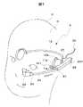
図1は、NEDシステム1をユーザUの頭部Hに装着した場合の外観の斜視図である。なお、本願では、頭部Hとは、NEDシステム1を利用するユーザUの頸部を含み、頸部から上の部分をさしている。 FIG. 1 is a perspective view of the appearance when the NED
NEDシステム1は、音声、音楽、効果音等の音響を発生させる機能を有すると共に、頭部Hに装着されるヘッドホン10と、ユーザUに対して画像を表示する機能を有するNED装置20と、を有する。また、NED装置20にはケーブル30が接続されている。ケーブル30は、不図示の電源供給ユニット、及び音響・画像信号生成ユニットから、電力と音響・画像信号を、NEDシステム1へ供給する。 The NED
ヘッドホン10は、右側スピーカ11aと、左側スピーカ11bと、右側耳架け部12aと、左側耳架け部12bと、右側スピーカ11a及び左側スピーカ11bを連結するヘッドホンアーム13と、を備えて構成される。 The
右側スピーカ11a、及び左側スピーカ11bは、音響出力機能を有し、ケーブル30からの音響信号が供給される。 The
右側耳架け部12aは、右側スピーカ11aに接続され、右側スピーカ11aが頭部Hに密着した状態で装着されるのを補助する。また、左側耳架け部12bは、左側スピーカ11bに接続され、左側スピーカ11bが頭部Hに密着した状態で装着されるのを補助する。 The right
ヘッドホンアーム13は、弾力によりユーザUの頭部Hを挟むと共に、右側スピーカ11aと左側スピーカ11bとを連結している。 The
NED装置20は、画像表示部22と、画像表示部22をユーザUの眼前の位置で支持可能とする支持部21と、支持部21とヘッドホンアーム13とを結合する結合部27と、支持部21に設けられた予備支持部40と、予備支持部40に設けられた頭部押圧検出センサ50と、を有している。 The NED
予備支持部40は、ユーザUの視野の中心と画像表示部22の画像の中心とが一致する場合のユーザUの視野に入らない支持部21の位置に、設けられている。 The
画像表示部22は、ケーブル30を介して送信された画像信号を再生して表示する。画像信号の再生・表示には、公知の技術を利用できる。 The
支持部21は、連結部23と、アーム部24と、収納部25と、を備えている。 The
連結部23は、画像表示部22とアーム部24とを連結している。連結部23は、ボールジョイントを用いて、連結部23を中心に画像表示部22の画像表示方向を連続的に変更可能としてもよい。 The connecting
アーム部24は、その一端が連結部23を介して画像表示部22に連結され、その他端側が収納部25にスライド可能に支持されている。また、アーム部24は、図2に示すように、頭部Hに対向する面に、保持部241と、ピン242と、バネ取り付け部243と、が取り付けられている。 One end of the
アーム部24は、管状のアームであり、頭部Hの側頭部から顔面部への曲線に沿ったカーブを成し、画像表示部22および連結部23の重量に耐える強度を有している。 The
収納部25は、アーム部24の少なくとも一部と共に、予備支持部40の少なくとも一部を、その内部に収納できる。 The
なお、本願では、図2に示す様に画像表示部22がユーザの眼前から退避しアーム部24の少なくとも一部が収納部25に収納される場合、アーム部24は収納位置にある、という。また、アーム部24により画像表示部22がユーザの眼前に支持される場合(図1)、アーム部24は突出位置にある、という。 In the present application, as shown in FIG. 2, when the
収納部25は、収納ケース251と、ディスプレイアーム位置検出センサ253と、支持部駆動ユニット254と、制御ユニット256と、モード切替スイッチ257と、を有している。 The
収納ケース251内の収納空間252は、アーム部24、及びアーム部24に沿った状態の予備支持部40を収納できる充分な大きさを有している。また、アーム部24の少なくとも一部を収納できる奥行きを有している。 The
ディスプレイアーム位置検出センサ253は、押圧センサである。ディスプレイアーム位置検出センサ253の取り付け位置は、収納空間252の最奥部である。本実施形態では、アーム部24が収納位置にある場合、アーム部24の画像表示部22が取り付けられていない一端246が、収納空間252の最奥部を押圧する。したがって、ディスプレイアーム位置検出センサ253は、アーム部24からの押圧を検知し、アーム部24が収納位置であることを検出する。 The display arm
支持部駆動ユニット254は、電動モータ(不図示)と、電動モータへの電力線及び制御信号線(不図示)と、モータ軸2541と、モータ軸2541に固定された駆動ローラ2542と、を備えている。駆動ローラ2542の外縁部は、湾曲したアーム部24の内周側面に接している。駆動ローラ2542は、電動モータからモータ軸2541に与えられた回転力によって、アーム部24をスライド移動させることができる。モータ軸2541の回転方向を変えることで、アーム部24のスライド移動方向も変えることができる。また、支持部駆動ユニット254には、電動モータが駆動されない場合に駆動ローラ2542の回転を止める、ストッパーが付いている。 The support
モード切替スイッチ257は、図2に示すように、その一部が収納ケース251の外側に突出しており、収納ケース251をつけたまま操作可能である。このモード切替スイッチ257によって、アーム部24のスライド操作を手動で行なう手動モードと電動により支持部駆動ユニット254を起動して行なう電動モードと、スイッチオフのオフモードとの、3つのモードを切り替える。なお、電動モード、及び手動モードの場合は、駆動ローラ2542の回転を止める前述のストッパーは、解放される。 As shown in FIG. 2, a part of the
図3は、アーム部24の一部、予備支持部40、及び頭部押圧検出センサ50の断面図である。 FIG. 3 is a cross-sectional view of a part of the
予備支持部40は、頭部Hを一定以上の圧力で押圧する押圧部401と、軸部402と、バネ取り付け部403と、軸部402をアーム部24に取り付ける取り付け部405と、を有している。また、押圧部401には、頭部Hに対する押圧を検出する頭部押圧検出センサ50が設けられている。更に、この押圧部401内には、頭部Hの動きの変化を検出する動きセンサ407が設けられている。 The
押圧部401は、球形であり、軸部402と連結している。また、押圧部401は、頭部Hを押圧する。 The
軸部402は、取り付け部405を介して、保持部241とピン242とによって、アーム部24に揺動可能に取り付けられている。 The
予備支持部40に押圧力を発生させる押圧力発生ユニット404は、電磁石4041、4042と、バネ4043と、を有している。電磁石4042は、軸部402に取り付けられ、電磁石4041は、電磁石4042と対向するように、アーム部24に取り付けられている。電磁石4041、4042には、収納部25から不図示の電力線を介して電力が供給されている。また、収納部25の制御ユニット256(図4:後述)によって、電磁石4041、4042への電流の方向・強さを制御できる。したがって、電磁石4041、4042が引き合うようにも、反発しあうようにも、電磁力を調整できる。 A pressing
バネ4043は、アーム部24上のバネ取り付け部243にその一端が取り付けられている。バネ4043の他端は、軸部402上のバネ取り付け部403に取り付けられている。バネ4043は、押圧部401がピン242を回転軸として、アーム部24に近づく方向に揺動運動した場合(矢印B方向)、その揺動運動を打ち消す方向(矢印A方向)にバネ4043の弾性力を働かせる。 One end of the
押圧部401の内部に設けられている動きセンサ407は、ジャイロセンサで構成されている。この動きセンサ407は、押圧部401が頭部Hに押圧した状態での、頭部Hの動きの変化を検出する。 The
頭部押圧検出センサ50は、押圧部401の表面で頭部Hに押圧する部分に装着され、その押圧力の値を検出する。 The head pressing
動きセンサ407の出力、及び頭部押圧検出センサ50の出力は、各々信号線を介して収納部25に設けられた制御ユニット256に送られる(図4)。 The output of the
なお、本願では、予備支持部40の押圧部401が頭部Hに押圧可能な位置にある場合、その位置を予備支持部40の押圧位置という。また、予備支持部40の押圧部401が頭部Hに押圧不能な位置にある場合、その位置を予備支持部40の退避位置という。この予備支持部40は、押圧位置と退避位置との間で、変位可能に設けられている。 In addition, in this application, when the
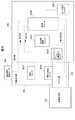
図4は、NEDシステム1の駆動・制御に関する機能ブロック図である。 FIG. 4 is a functional block diagram relating to driving and control of the
制御ユニット256は、収納部25に設けられたディスプレイアーム位置検出センサ253、支持部駆動ユニット254、及びモード切替スイッチ257と、予備支持部40に配置された動きセンサ407及び押圧力発生ユニット404と、頭部押圧検出センサ50と、画像表示部22と、にそれぞれ信号線を介して接続されている。制御ユニット256は、それらの信号線を介して信号の送受信を行なう。また、制御ユニット256は、頭部押圧検出センサ50の出力5000から、押圧値が予め定めた一定の範囲に留まるように、押圧力発生ユニット404を制御する。また、制御ユニット256は、ディスプレイアーム位置検出センサ253の出力2530から、アーム部24が突出位置あるいは収納位置にあるように、支持部駆動ユニット254を制御する。 The
NEDシステム1の使用開始から使用終了までの制御、及び動作を、順に説明する。なお、以下の説明では、ブロック間の制御信号は記載せず、各センサからのデータのみを記載する。 Control and operation from the start of use to the end of use of the
(1)ユーザUは、本実施形態のNEDシステム1を頭部Hに装着する。(2)ユーザUは、モード切替スイッチ257により電動モードと手動モードとのいずれかを選択する。 (1) The user U wears the
電動モードを選択した場合、(3)制御ユニット256は、支持部駆動ユニット254を制御し、アーム部24を収納位置から突出位置へと繰り出させる。その結果、画像表示部22は片目眼前で支持される。 When the electric mode is selected, (3) the
手動モードを選択した場合は、(4)制御ユニット256は、支持部駆動ユニット254に備わる、アーム部24に対するストッパーをオフとする。(5)ユーザUが手動でアーム部24を収納位置から突出位置へと繰り出す。 When the manual mode is selected, (4) the
以上の(3)あるいは(4)、(5)が行われている過程で、以下の(6)〜(7)が平行して行なわれる。 In the process in which the above (3), (4), and (5) are performed, the following (6) to (7) are performed in parallel.
(6)ディスプレイアーム位置検出センサ253は、アーム部24の端部246が収納部25の最奥部から離れたことを検出し、制御ユニット256に支持部位置検出信号2530を送信する。(7)制御ユニット256は支持部位置検出信号2530を受信し、押圧力発生ユニット404を制御し、予備支持部40を退避位置から押圧位置へと変位させる。 (6) The display arm
さらに、以下の制御・動作が行なわれる。 Further, the following control / operation is performed.
(8)制御ユニット256は、頭部押圧検出センサ50を起動する。(9)制御ユニット256は、動きセンサ407を起動する。(10)予備支持部40の押圧部401は、頭部Hの側頭部に対し押圧を行なう。(11)頭部押圧検出センサ50は、押圧値を検出し、制御ユニット256に、頭部押圧検出信号5000を送る。(12)制御ユニット256は頭部押圧検出信号5000を受け、押圧値が予め定めた一定の範囲に入った場合、画像表示部22に画像を表示させる。(13)制御ユニット256は、更に、押圧力の値が予め定めた一定の範囲に維持されるように、押圧力発生ユニット404を制御する。具体的には、押圧力発生ユニット404への電流を制御し、電磁石4041,4042の電磁力を調整する。 (8) The
ユーザUが、画像の観察の終了を意図した場合、NEDシステム1の動作・制御は以下のようになる。 When the user U intends to end the image observation, the operation / control of the
(14)ユーザUがモード切替スイッチ257をオフモードの位置に戻すと、制御ユニット256は、画像表示部22に画像表示を中止させる。(15)制御ユニット256は、押圧力発生ユニット404を駆動し、予備支持部40を押圧位置から退避位置へと移行させる。(16)ユーザUが電動モードを利用していた場合、制御ユニット256は、支持部駆動ユニット254を駆動し、アーム部24を突出位置から収納位置へと移行させる。ユーザUが手動モードを利用していた場合、ユーザUは手動によりアーム部24を収納部25に収納する。その際、予備支持部40も、収納部25に収納される。 (14) When the user U returns the
なお、制御ユニット256が、動きセンサ407の動き検出信号4070を利用し、押圧力発生ユニット404を制御することも考えられる。例えば、制御ユニット256が、動きセンサ407からの動き検出信号4070を基に、頭部Hの動きの変化を算出する。その変化にあわせて制御ユニット256が、押圧部401の押圧の値が予め定めた一定の範囲に留まるように、押圧力発生ユニット404をコントロールしてもよい。また、予備支持部40の退避位置および押圧位置の切り替えを手動で行ってもよい。その場合、モード切替スイッチ257の手動モードの下で行なえばよい。また、押圧力発生ユニット404では、電磁石4041、4042のいずれか一方を鉄などの磁性体としてもよい。予備支持部40を押圧位置にする場合は、電磁力をオフとし、バネ4043の弾性力のみを用いてもよい。予備支持部40を退避位置にする場合は、電磁石の電磁力を制御し、弾性力より大きい電磁力で磁性体を引き付ければよい。更に、退避位置を維持するロック機構を設けてもよい。 It is also conceivable that the
本実施形態のNED20では、図1に示すようにユーザUが画像表示部22の画像を観察する際の視野の外側になる、アーム部24上の収納部25側の位置に、予備支持部40を設けている。したがって、予備支持部40は、ユーザUの視野をユーザUに不快感を与える程度に遮ることが少ない。よって、第1実施形態のNEDシステム1は、周囲の視認性を損なわずに済む。 In the
本発明の第2実施形態に係るNEDシステム2について、図5〜6を用いて説明する。 The
本実施形態では、図5に示すように、第1実施形態と同様の予備支持部40を、アーム部24ではなく、収納部25に設けている。したがって、アーム部24に設けられていた保持部241と、ピン242と、バネ取り付け部243は、新たに収納部25に設けられる。また、押圧力発生ユニット404の電磁石4041は、収納部25上に配置される。また、バネ4043の一端も収納部25に固定される。その他の構成は、第1実施例と共通である。よって、共通の構成要素には同じ番号を振ってある。また、共通の構成要素、及びその動作・制御について、重複する説明は省略する。なお、図5では、アーム部24が突出位置にあり、収納部25に揺動可能に設けられた予備支持部40が、側頭部を押圧する押圧位置にある状態を示している。 In the present embodiment, as shown in FIG. 5, a
NEDシステム2の装着時の動作は、(1)ユーザUのモード切替スイッチ257の選択により、アーム部24は、手動あるいは支持部駆動ユニット254で突出位置に繰り出される(矢印A)。(2)その過程で、第1実施形態と同様の制御により押圧力発生ユニット404が駆動し、(3)予備支持部40は、押圧部401が頭部Hの側頭部を押圧する押圧位置をとる(矢印B)。 The operation when the
図6は、本実施形態のNEDシステム2において、アーム部24が収納位置にある場合の外観の斜視図である。収納部25に設けられた予備支持部40は退避位置にある。 FIG. 6 is a perspective view of the appearance of the
NEDシステム2の脱着時の動作は、(1)ユーザUのモード切替スイッチ257の選択により、アーム部24は、手動あるいは支持部駆動ユニット254により収納位置に収納される(矢印C)。(2)アーム部24が収納される過程で、第1実施形態と同様の制御により押圧力発生ユニット404が駆動し、(3)予備支持部40は、退避位置をとる(矢印D)。 The operation when the
なお、本実施形態では、予備支持部40は頭部Hの側頭部を押圧する。しかし、頭部Hの側頭部ではなく、左スピーカ11bを押圧するようにしてもよい。また、第1実施形態と同様に、頭部センサ407により頭部Hの動き変化を検出してもよい。そして、頭部Hの動き変化に対応した予備支持部40の押圧制御を行ってもよい。また、第1実施形態と同様に、予備支持部40の退避位置および押圧位置の切り替えを手動で行ってもよい。その場合、モード切替スイッチ257の手動モードの下で行なってもよい。 In the present embodiment, the
第2実施形態では、収納部25に設けられた予備支持部40により、側頭部を押圧している。したがって、予備支持部40がユーザUの視野の外側に位置しており、予備支持部40は、画像を観察中のユーザUの視野に入りにくくなる。したがって、本実施形態のNED20では、画像表示部22のブレを抑えつつ、周囲の視認性が良好となる。 In the second embodiment, the temporal portion is pressed by the
本発明の第3実施形態に係るNEDシステム3について、図7〜10を用いて説明する。 A
本実施形態では、図7に示すように、新たな機構の予備支持部41を、収納部25に設けている。また、予備支持部41が、NEDシステム3の装着前から押圧可能な押圧位置になっている。その他は、第2実施形態と共通である。よって、共通の構成要素には同じ番号を振ってある。また、共通の構成要素、及びその動作について、重複する説明は省略する。なお、図7では、アーム部24が突出位置にあり、収納部25に設けられた予備支持部41が、押圧位置にある状態を示している。 In the present embodiment, as shown in FIG. 7, a
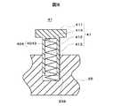
図8は、押圧位置にある予備支持部41、及び収納部25の一部の断面図である。 FIG. 8 is a cross-sectional view of a part of the
予備支持部41は、円盤状の押圧部411、押圧部411と一端で連結し内部に円筒状の中空部413を有する円筒412、を備えている。また、円筒412の開放端部は、収納部25に設けられた円筒412と略同径の穴部にスライド可能に挿入されている。また、予備支持部41は、押圧力発生ユニット404を有している。 The
押圧力発生ユニット404は、バネ4043を有している。バネ4043は、中空部413と略同径である。バネ4043の一端は、バネ取り付け部414に取り付けられている。バネ4043の他端は、収納部25の穴部底部に設けられたバネ取り付け部258に取り付けられている。 The pressing
バネ取り付け位置414にかかるバネ4043の弾性力は、NEDシステム3の姿勢にかかわらず、予備支持部41が押圧位置を維持することができるように調整されている。 The elastic force of the
NEDシステム3(図7)の動作・制御は、第2実施形態とほぼ同様である。しかし、予備支持部41が、装着前から押圧可能な押圧位置になっていることが異なっている。つまり、ユーザUは押圧位置にある予備支持部41を頭部Hで押し戻すようにして、NEDシステム3を、その頭部Hに装着する。その後の装着動作は、予備支持部41が常に押圧可能な押圧位置になっていることを除いて、第2の実施形態と同様である。 The operation and control of the NED system 3 (FIG. 7) is almost the same as in the second embodiment. However, the difference is that the
なお、収納部25の穴部底部(図8)に電磁石を設け、押圧部411の一部に鉄などの磁性体を設ける構成も考えられる。この構成では、予備支持部41を退避位置にする際に、バネ4043の弾性力に逆らい、電磁力により押圧部411を穴部底部の電磁石に引き寄せればよい。更に、予備支持部41の少なくとも一部を、収納部25の穴部に収納してもよい。また、予備支持部41を押圧位置にするには、電磁石による電磁力をオフにして、バネ4043の弾性力だけで予備支持部41を突出させればよい。 In addition, the structure which provides an electromagnet in the hole bottom part (FIG. 8) of the
第3実施形態では、第2実施形態と同様に、収納部25に設けられた予備支持部41により、側頭部を押圧している。したがって、予備支持部41がユーザUの視野の外側に位置しており、予備支持部41は、画像を観察中のユーザUの視野に入りにくくなる。したがって、本実施形態のNED装置では、画像表示部22のブレを抑えつつ、周囲の視認性が良好となる。 In the third embodiment, similarly to the second embodiment, the temporal region is pressed by the
図9は、第3実施形態の第1変形例を示している。第1変形例では、結合部27は、収納部25を、ヘッドホンアーム13ではなく、左スピーカ11bに結合している。その他の構成及び動作は第3実施形態と同様である。 FIG. 9 shows a first modification of the third embodiment. In the first modification, the
第1変形例では、収納部25を左スピーカ11bに結合することで、予備支持部41が画像を観察中のユーザUの視野に入りにくくなる。したがって、本変形例のNED装置では、画像表示部22のブレを抑えつつ、周囲の視認性が良好となる。 In the first modification, the
図10は、第3実施形態の第2変形例を示している。第2変形例では、予備支持部41が、頭部Hではなく、左スピーカ11bを押圧している。その他の構成及び動作は第3実施形態と同様である。 FIG. 10 shows a second modification of the third embodiment. In the second modification, the
第2変形例では、予備支持部41が左スピーカ11bを介して、頭Hに押圧をかけるので、予備支持部41が画像を観察中のユーザUの視野に入りにくくなる。したがって、本変形例のNED20では、画像表示部22のブレを抑えつつ、周囲の環境の視認性が良好となる。 In the second modification, the
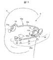
次に、本発明の第4実施形態に係るNEDシステム4について、図11〜14を用いて説明する。なお、図11は、本実施形態に係るNEDシステム4の斜視図で、図12は、NEDシステム4の要部切欠き平面図で、図13は、図12におけるA−A線断面図である。 Next, an NED system 4 according to a fourth embodiment of the present invention will be described with reference to FIGS. 11 is a perspective view of the NED system 4 according to the present embodiment, FIG. 12 is a cutaway plan view of the main part of the NED system 4, and FIG. 13 is a cross-sectional view taken along line AA in FIG. .
本実施形態のNEDシステム4も、図11に示すように、以上の実施形態と同様、ヘッドホン10aとNED装置20aとを備えている。 As shown in FIG. 11, the NED system 4 of this embodiment also includes a
ヘッドホン10aは、右側スピーカ11aと、左側スピーカ11bと、右側スピーカ11aと左側スピーカ11bとを連結するヘッドホンアーム13aと、を有している。ヘッドホンアーム13aは、以上の実施形態と異なり、各スピーカ11a,11bの傍で湾曲しており、この湾曲部分が耳掛け部14を形成している。 The
また、NED装置20aは、以上の実施形態と同様、画像表示部22、支持部21、結合部27と、予備支持部40aを備えている。さらに、本実施形態のNED装置20aは、図12に示すように、予備支持部40aの突出量を調節する突出量調節部60と、結合部27から支持部21までの距離を変える距離調節具65、結合部27に対して支持部21を揺動可能に取り付ける関節70と、予備支持部40aに押圧力Fを発生させる押圧力発生手段としてのスプリングコイル75と、を備えている。 The
支持部21の収納部25の画像表示部22側には、予備支持部40aを取り付けるための取り付け部分が形成されている。本実施形態の予備支持部40aの軸部には、雄ネジ61が形成されており、収納部25の取り付け部分には、予備支持部40aの雄ネジ61が螺合する雌ネジ62が形成されている。突出量調節部60は、これら予備支持部40aの軸部に形成された雄ネジ61と収納部25の取り付け部分に形成された雌ネジ62と、を有して構成されている。従って、予備支持部40aは、軸部を回転させることにより、収納部25に対しての突出量を変えることができる。 An attachment portion for attaching the
結合部27には、図12及び図13に示すように、支持部21側に突出した凸部27aが形成されている。距離調節具65は、この結合部27の凸部27aに嵌まり込む嵌合凹部65bと、結合部27の凸部27aと同形状の凸部65aとを有している。この距離調節具65は、これを設けるか、又はこれを1以上設けるか、つまりこれを重ね合わせる個数により、結合部27と支持部21との接続部分における、結合部27から支持部21までの距離を調節することができる。 As shown in FIGS. 12 and 13, the
関節70は、結合部27の凸部27a又は距離調節具65の凸部65aに嵌まり込む軸受部材71と、この軸受部材71に対して回転可能な軸部材72とを有している。この軸部材72は、一方の端部側が軸受部材71に回転可能に受けられ、他方の端部が収納部25に固定されている。また、この軸部材72は、本実施形態のニアアイディスプレイシステム4を頭部Hに装着した際、ほぼ鉛直方向と平行になるように設けられている。従って、支持部21は、この関節70により、本実施形態のニアアイディスプレイシステム4を頭部Hに装着した際の水平面内、言い換えると予備支持部40aの押圧力Fの作用方向と結合部27とを含む面内で、結合部27に対して揺動Vθすることができる。 The joint 70 includes a bearing
スプリングコイル75は、図12に示すように、関節70の軸部材72を基準にして画像表示部側に配置され、その一方の端部が関節70の軸受部材71に取り付けられ、その他方の端部が収納部25の外周側の内壁面に取り付けられている。このコイルスプリング75は、引っ張られた状態で設置されているため、支持部21と共に、この支持部21に設けられている予備支持部40aを頭部Hに近づく方向に付勢している。したがって、予備支持部40aは、このコイルスプリング75により、頭部Hに対する一定の押圧力Fを確保している。 As shown in FIG. 12, the
以上のように、本実施形態では、距離調節具65の数量を変えることにより、及び/又は予備支持部40aを回転させることにより、予備支持部40aの押圧力Fの作用方向を含む面内、つまり装置使用時における水平面内で、支持部21を傾けることができる。このため、頭部Hに対する画像表示部22の左右方向の位置を調節することができる。特に、突出量調節部60を設けたことで、装置を頭部Hに装着し、予備支持部40aによる押圧力Fが作用している状態であっても、頭部Hに対する画像表示部22の左右方向の位置を微調節することができる。 As described above, in the present embodiment, by changing the quantity of the
なお、本実施形態では、予備支持部40aの押圧力Fの作用方向を含む面内で支持部21を傾けるために、距離調節具65と突出量調節部60とを設けたが、いずれか一方のみであってもよい。但し、距離調節具65は、装置の使用前に予め設けておく必要がある一方で、突出量調節部60は、装置の使用前であろうが使用中であろうが支持部21の傾きを変えることができるので、いずれか一方のみを設ける場合には、装置の使用中であっても支持部21の傾きを変えることができる方、つまり、本実施形態では突出量調節部60のみを設けることが好ましい。 In the present embodiment, the
また、本実施形態の突出量調節部60は、ネジ構造により予備支持部40aの突出量を調節するものであるが、予備支持部40aの突出量を調節できれば、例えば、カム構造を採用しても、電磁石を用いた構造等を採用してもよい。さらに、本実施形態では、押圧力発生手段として、コイルスプリング75を用いたが、このコイルスプリング75の替わりに、他の弾性部材や、電磁石等を用いてもよいことは言うまでもない。また、本実施形態では、距離調節手段として距離調節具65を用いたが、この替わりに、突出量調節部と同様にネジ構造等を採用してもよい。 Further, the protrusion
以上のように、本発明に係る各実施形態によれば、周囲の環境の視認性のよいNED装置を提供することができる。特に、予備支持部を支持部に設けることで、予備支持部が画像観察中のユーザの視野に入ることが少なくなり、NED装置の周囲の視認性が良好となる。 As described above, according to each embodiment of the present invention, it is possible to provide an NED device with good visibility of the surrounding environment. In particular, by providing the preliminary support portion in the support portion, the preliminary support portion is less likely to enter the field of view of the user during image observation, and the visibility around the NED device is improved.
なお、本発明は上記の実施形態に限定されるものではなく、その要旨の範囲内で数々の変形が可能である。例えば、NED装置は頭部の左右のどちら側にも装着できるようにしてもよく、そのために制御ユニットで表示画像を適宜切り替えられるようにしてもよい。 In addition, this invention is not limited to said embodiment, Many deformation | transformation are possible within the range of the summary. For example, the NED device may be mounted on either the left or right side of the head, and for that purpose, the display image may be switched appropriately by the control unit.
また、電源を外部に設けず、例えば収納部にバッテリを設けてもよい。また、音響・映像信号を無線で受信するようにしてもよい。 Further, for example, a battery may be provided in the storage unit without providing the power source outside. Also, audio / video signals may be received wirelessly.
1…ニアアイディスプレイ装置システム、10,10a…ヘッドホン、11a、b…左・右スピーカ、12a、b…左・右耳かけ部、13,13a…ヘッドホンアーム、20,20a…ニアアイディスプレイ装置、21…支持部、22…画像表示部、23…連結部、24…アーム部、25…収納部、27…結合部、256…制御ユニット、257…モード切替スイッチ、27…結合部、30…ケーブル、40,40a…予備支持部、60…突出量調節部、65…距離調節具、70…関節、404…押圧力発生ユニット、
U…ユーザ、H…頭部
DESCRIPTION OF
U ... user, H ... head
Claims (11)
Translated fromJapanese画像を表示する画像表示部と、
一方の端部に前記画像表示部が取付けられ、該画像表示部を前記ユーザの眼前の位置に支持する支持部と、
前記ユーザの頭部に装着される頭部装着部中で、該ユーザの耳に対応する位置又は該耳より後方の該ユーザの頭部に対応する位置に、前記支持部の他方の端部を結合する結合部と、
前記支持部の前記一方の端部と前記他方の端部との間であって、前記ユーザの耳より前方の側頭部に対応する位置に設けられ、該側頭部を押圧する予備支持部と、
を備えていることを特徴とするニアアイディスプレイ装置。In a near-eye display device that displays an image in front of the user's eyes,
An image display unit for displaying an image;
The image display unit is attached to one end, and a support portion whichsupportsthe image display unitin front of theposition of the user,
The other end of the support unit is coupledto a position corresponding to the user's ear or to a position corresponding to the user's head behind the ear in the head mounting part to be mounted on theuser's head. A connecting portion to
A preliminary support portion providedbetween the one end portion and the other end portion of the support portion and provided ata position corresponding to the temporal region infront of the user's ear and pressing the temporal portion; ,
A near-eye display device comprising:
弾性力及び/又は電磁力により、前記予備支持部に前記側頭部を押圧する押圧力を発生させる押圧力発生手段を備えている、
ことを特徴とするニアアイディスプレイ装置。The near eye display device accordingto claim 1 ,
A pressing force generating means for generating a pressing force for pressing the temporal portion on the preliminary support portion by elastic force and / or electromagnetic force;
A near-eye display device.
前記予備支持部は、該予備支持部が前記側頭部に対し押圧可能な押圧位置と、該予備支持部が前記頭部に対し押圧不能な退避位置との間で、変位可能に設けられている、
ことを特徴とするニアアイディスプレイ装置。The near eye display device accordingto claim 2 ,
The preliminary support portion includes a pressing position capable pressing the pre support part with respect to thetemporal portion, between the pre support portion of the pressing non retracted position relative to the head, it is provided displaceably Yes,
A near-eye display device.
前記押圧位置の前記予備支持部が前記頭部に対して加える押圧力の値を検出する押圧力検知手段を備え、
前記押圧力発生手段は、前記押圧力検知手段で検知された前記値が予め定めた一定の範囲内の値を保つように前記押圧力を制御する、
ことを特徴とするニアアイディスプレイ装置。In the near eye display device according toclaim 3 ,
A pressing force detecting means for detecting a value of the pressing force applied to the head by the preliminary support portion at the pressing position;
The pressure generation means controls the pressure so that the value detected by the pressure detection means maintains a value within a predetermined range;
A near-eye display device.
前記支持部は、前記画像表示部が取り付けられたアーム部、及び前記アーム部を収納する収納部を有し、
前記収納部は、前記画像表示部がユーザの眼前に支持される突出位置と、前記画像表示部がユーザの眼前から退避して前記アーム部の少なくとも一部が前記収納部に収納される収納位置と、の間で、前記アーム部をスライド可能に支持し、
前記アーム部が前記収納位置に存在するとき、前記予備支持部が前記退避位置にある、
ことを特徴とするニアアイディスプレイ装置。In the near eye display device according to any one ofclaims 3 and 4 ,
The support unit includes an arm unit to which the image display unit is attached, and a storage unit that stores the arm unit,
The storage unit includes a protruding position where the image display unit is supported in front of the user's eyes, and a storage position where the image display unit is retracted from the user's eyes and at least a part of the arm unit is stored in the storage unit. And slidably support the arm portion,
When the arm portion is in the storage position, the preliminary support portion is in the retracted position;
A near-eye display device.
前記アーム部が前記突出位置に存在しているときに、前記予備支持部が前記押圧位置にある、
ことを特徴とするニアアイディスプレイ装置。The near eye display device according toclaim 5 ,
When the arm portion is in the protruding position, the preliminary support portion is in the pressing position;
A near-eye display device.
前記押圧力の作用方向と前記結合部とを含む面内で、前記結合部を基準とする前記支持部の傾きを調節する傾き調節手段を備えている、
ことを特徴とするニアアイディスプレイ装置。In the near eye display device according to any one ofclaims 2 to 6 ,
In a plane including the action direction of the pressing force and the coupling portion, an inclination adjusting means for adjusting the inclination of the support portion with respect to the coupling portion is provided.
A near-eye display device.
前記傾き調節手段は、前記支持部に対する前記予備支持部の突出量を調節する突出量調節手段を有している、
ことを特徴とするニアアイディスプレイ装置。The near-eye display device according toclaim 7 ,
The inclination adjusting means includes a protrusion amount adjusting means for adjusting a protrusion amount of the preliminary support portion with respect to the support portion.
A near-eye display device.
前記傾き調節手段は、前記結合部と前記支持部との接続部分における、該結合部から該支持部までの距離を変える距離調節手段を有している、
ことを特徴とするニアアイディスプレイ装置。The near eye display device according to any one ofclaims 7 and 8 ,
The inclination adjusting means includes distance adjusting means for changing a distance from the coupling portion to the support portion at a connection portion between the coupling portion and the support portion.
A near-eye display device.
前記押圧力発生手段は、前記結合部又は該結合部近傍に配置され、前記支持部の前記画像表示部側を該押圧力の作用方向に傾ける力を発生させる、
ことを特徴とするニアアイディスプレイ装置。The near eye display device according to any one ofclaims 7 to 9 ,
The pressing force generating means is disposed in the coupling portion or in the vicinity of the coupling portion, and generates a force for inclining the image display unit side of the support portion in the direction of the pressing force.
A near-eye display device.
前記押圧力の作用方向と前記結合部とを含む面内で、前記結合部に対して前記支持部を揺動可能に取り付ける関節を有する、
ことを特徴とするニアアイディスプレイ装置。In the near eye display device according to any one ofclaims 2 to 10 ,
In a plane including the direction of action of the pressing force and the coupling portion, the joint has a joint for swingably attaching the support portion to the coupling portion.
A near-eye display device.
Priority Applications (6)
| Application Number | Priority Date | Filing Date | Title |
|---|---|---|---|
| JP2004103724AJP4389631B2 (en) | 2004-01-19 | 2004-03-31 | Near eye display device |
| PCT/JP2004/019352WO2005064930A1 (en) | 2003-12-26 | 2004-12-24 | Near-eye display device, headphone, and system provided with these |
| KR1020067012813AKR101196275B1 (en) | 2003-12-26 | 2004-12-24 | Near eye display device, headphone, and system provided with these |
| EP04807709AEP1699237B1 (en) | 2003-12-26 | 2004-12-24 | Near-eye display device, headphone, and system provided with these |
| US11/473,559US20060238878A1 (en) | 2003-12-26 | 2006-06-23 | Wearable display unit, headphones and system provided with these |
| US12/753,797US8362974B2 (en) | 2003-12-26 | 2010-04-02 | Wearable display unit, headphones and system provided with these |
Applications Claiming Priority (2)
| Application Number | Priority Date | Filing Date | Title |
|---|---|---|---|
| JP2004010781 | 2004-01-19 | ||
| JP2004103724AJP4389631B2 (en) | 2004-01-19 | 2004-03-31 | Near eye display device |
Publications (2)
| Publication Number | Publication Date |
|---|---|
| JP2005236941A JP2005236941A (en) | 2005-09-02 |
| JP4389631B2true JP4389631B2 (en) | 2009-12-24 |
Family
ID=35019398
Family Applications (1)
| Application Number | Title | Priority Date | Filing Date |
|---|---|---|---|
| JP2004103724AExpired - Fee RelatedJP4389631B2 (en) | 2003-12-26 | 2004-03-31 | Near eye display device |
Country Status (1)
| Country | Link |
|---|---|
| JP (1) | JP4389631B2 (en) |
Families Citing this family (2)
| Publication number | Priority date | Publication date | Assignee | Title |
|---|---|---|---|---|
| JP6647036B2 (en)* | 2015-12-24 | 2020-02-14 | オリンパス株式会社 | Wearable device |
| KR101865117B1 (en)* | 2016-09-29 | 2018-06-07 | 주식회사 이랜텍 | Head mount display device |
- 2004
- 2004-03-31JPJP2004103724Apatent/JP4389631B2/ennot_activeExpired - Fee Related
Also Published As
| Publication number | Publication date |
|---|---|
| JP2005236941A (en) | 2005-09-02 |
Similar Documents
| Publication | Publication Date | Title |
|---|---|---|
| KR20060103939A (en) | Near eye display device, headphones, and system with them | |
| KR100280860B1 (en) | Image display | |
| JP5195426B2 (en) | Output device and video display device | |
| JP4426918B2 (en) | Information display system | |
| JP5023755B2 (en) | Image display device | |
| EP1207690A1 (en) | Head-mounted display | |
| JP2009171505A (en) | Head mounted display | |
| US20090115687A1 (en) | Video display device | |
| JP4389631B2 (en) | Near eye display device | |
| JP4366943B2 (en) | Head mounted display | |
| JPH0795498A (en) | Glasses type display | |
| JP5055585B2 (en) | Head mounted display | |
| US20240288658A1 (en) | Display apparatus | |
| JP2008070551A (en) | Head-mounted display | |
| JP5055584B2 (en) | Head mounted display device | |
| JP2005192083A (en) | Information display device | |
| WO2021070656A1 (en) | Head-mounted image display device | |
| JP2008028552A (en) | Display device | |
| JP2004236241A (en) | Display device | |
| JP2007325105A (en) | Portable display device | |
| JP2005300730A (en) | Head mounted display | |
| JP2008147744A (en) | Output device | |
| JP2004233899A (en) | Head mounted display device | |
| JP2008271054A (en) | Body-mounted display | |
| JP2007219116A (en) | Head mounted display |
Legal Events
| Date | Code | Title | Description |
|---|---|---|---|
| A621 | Written request for application examination | Free format text:JAPANESE INTERMEDIATE CODE: A621 Effective date:20070220 | |
| A131 | Notification of reasons for refusal | Free format text:JAPANESE INTERMEDIATE CODE: A131 Effective date:20090623 | |
| A521 | Written amendment | Free format text:JAPANESE INTERMEDIATE CODE: A523 Effective date:20090812 | |
| TRDD | Decision of grant or rejection written | ||
| A01 | Written decision to grant a patent or to grant a registration (utility model) | Free format text:JAPANESE INTERMEDIATE CODE: A01 Effective date:20090915 | |
| A01 | Written decision to grant a patent or to grant a registration (utility model) | Free format text:JAPANESE INTERMEDIATE CODE: A01 | |
| A61 | First payment of annual fees (during grant procedure) | Free format text:JAPANESE INTERMEDIATE CODE: A61 Effective date:20090928 | |
| FPAY | Renewal fee payment (event date is renewal date of database) | Free format text:PAYMENT UNTIL: 20121016 Year of fee payment:3 | |
| R150 | Certificate of patent or registration of utility model | Ref document number:4389631 Country of ref document:JP Free format text:JAPANESE INTERMEDIATE CODE: R150 Free format text:JAPANESE INTERMEDIATE CODE: R150 | |
| FPAY | Renewal fee payment (event date is renewal date of database) | Free format text:PAYMENT UNTIL: 20121016 Year of fee payment:3 | |
| FPAY | Renewal fee payment (event date is renewal date of database) | Free format text:PAYMENT UNTIL: 20151016 Year of fee payment:6 | |
| S531 | Written request for registration of change of domicile | Free format text:JAPANESE INTERMEDIATE CODE: R313531 | |
| R350 | Written notification of registration of transfer | Free format text:JAPANESE INTERMEDIATE CODE: R350 | |
| R250 | Receipt of annual fees | Free format text:JAPANESE INTERMEDIATE CODE: R250 | |
| R250 | Receipt of annual fees | Free format text:JAPANESE INTERMEDIATE CODE: R250 | |
| R250 | Receipt of annual fees | Free format text:JAPANESE INTERMEDIATE CODE: R250 | |
| R250 | Receipt of annual fees | Free format text:JAPANESE INTERMEDIATE CODE: R250 | |
| R250 | Receipt of annual fees | Free format text:JAPANESE INTERMEDIATE CODE: R250 | |
| LAPS | Cancellation because of no payment of annual fees |