JP4389276B2 - Vehicle obstacle warning device - Google Patents
Vehicle obstacle warning deviceDownload PDFInfo
- Publication number
- JP4389276B2 JP4389276B2JP30798197AJP30798197AJP4389276B2JP 4389276 B2JP4389276 B2JP 4389276B2JP 30798197 AJP30798197 AJP 30798197AJP 30798197 AJP30798197 AJP 30798197AJP 4389276 B2JP4389276 B2JP 4389276B2
- Authority
- JP
- Japan
- Prior art keywords
- obstacle
- vehicle
- movement direction
- distance
- detected
- Prior art date
- Legal status (The legal status is an assumption and is not a legal conclusion. Google has not performed a legal analysis and makes no representation as to the accuracy of the status listed.)
- Expired - Lifetime
Links
- 238000001514detection methodMethods0.000claimsdescription37
- 230000008859changeEffects0.000claimsdescription8
- 238000013459approachMethods0.000claimsdescription7
- 238000000034methodMethods0.000description20
- 238000010586diagramMethods0.000description16
- 230000008569processEffects0.000description14
- 230000004397blinkingEffects0.000description3
- 230000007423decreaseEffects0.000description3
- 230000003449preventive effectEffects0.000description3
- 230000004069differentiationEffects0.000description2
- 230000000007visual effectEffects0.000description2
- 230000003247decreasing effectEffects0.000description1
- 230000000694effectsEffects0.000description1
- 238000000605extractionMethods0.000description1
- 230000006870functionEffects0.000description1
- 238000003384imaging methodMethods0.000description1
- 239000004973liquid crystal related substanceSubstances0.000description1
- 238000003672processing methodMethods0.000description1
- 230000004044responseEffects0.000description1
Images


Classifications
- G—PHYSICS
- G08—SIGNALLING
- G08G—TRAFFIC CONTROL SYSTEMS
- G08G1/00—Traffic control systems for road vehicles
- G08G1/16—Anti-collision systems
- G08G1/166—Anti-collision systems for active traffic, e.g. moving vehicles, pedestrians, bikes
Landscapes
- Physics & Mathematics (AREA)
- General Physics & Mathematics (AREA)
- Traffic Control Systems (AREA)
- Radar Systems Or Details Thereof (AREA)
- Optical Radar Systems And Details Thereof (AREA)
- Control Of Driving Devices And Active Controlling Of Vehicle (AREA)
Description
Translated fromJapanese【0001】
【発明の属する技術分野】
本発明は、ドライバーが車両を安全に運転することができるように支援するシステムの技術分野に属し、特に、車両前方を横切る障害物に関する情報をドライバーに提供することによってドライバーの安全運転を支援する障害物警報装置の技術分野に属する。
【0002】
【従来の技術】
車両のドライバーは、フロントガラスや左右のドアウインドを通して、あるいはルームミラーや左右のドアミラーを介して、運転席の位置から周囲の状況を主に視覚により認知し、これにより自車の走行進路の判断やスピードコントロール等を行なって、前後車両との間の適切な車間距離の保持や、円滑な車線変更もしくは高速道路等での合流、あるいは横断歩道のある交差点の通過、右折、左折等に努める。したがって、ドライバーが車両を安全に運転するためには、自車の周囲に存在する他の走行車両や歩行者等の障害物の様子を知ることが重要なことであり、そのために、ドライバーが自己の視覚により認識する情報以外に、自車の周囲に存在するそのような障害物を機器により検出してドライバーに報知するように構成された運転支援システムが知られている。
【0003】
この種の運転支援システムとして、例えば、特開平7−63846号公報には、車体側部に設けた複数の超音波センサにより車両周囲の障害物を検出し、これにより車庫入れや縦列駐車における障害物との接触等を回避しようとする技術が開示されている。
【0004】
【発明が解決しようとする課題】
ところで、従来より、この種の運転支援システムは、車両の周囲の障害物を検出するも、それは一般に、上記公報にも開示されているように、自車の周囲で同方向に走行中の車両や、近接位置にある静止物体を対象とし、もって車線変更時の後続他車両との接触や、車庫入れ時のこすり等を回避しようとするもので、そのために、障害物との距離や相対速度等を自車の走行方向において検出したり、自車の近くに障害物があるかないかを検出するものであった。
【0005】
しかしながら、車両の周囲の障害物のなかには、自車の走行方向に沿って移動するものや静止物体ばかりではなく、例えば横断歩行者のように車両の進行方向を横切るような動きをするものもあり、現在のところ、このような横方向の動きをする移動物体の存在を的確に把握して、ドライバーに明確なかたちで知らせるという技術の提案は見当たらない。もちろん、車両の周囲の障害物を検出することにより、自車の前方に存在する障害物を検出することはできるが、それが横断歩行者等に特有の自車の進行方向を横切るような動きをするものであるかどうかについての判断を特に行なう技術の提案は見出されないのである。
【0006】
そこで、本発明は、車両前方を横切るような横断歩行者等の動きを的確に検出して、ドライバーに適切な運転操作を促すことを目的とする障害物警報装置の提供を課題とする。
【0007】
【課題を解決するための手段】
上記課題を解決するため、本発明では次のような手段を用いる。
【0008】
まず、本願の特許請求の範囲の請求項1に記載の発明(以下「第1発明」という。)は、ドライバーの安全運転を支援する障害物警報装置であって、車両前方に存在する障害物を検出する障害物検出手段と、該障害物検出手段で検出された障害物の移動方向を検出する移動方向検出手段と、該移動方向検出手段で検出された障害物の移動方向に関する情報をドライバーに提供する移動情報提供手段とを備え、上記移動情報提供手段は、視覚を通じて情報を提供する表示部を有し、該表示部に、自車の進行方向の前方を横切る動きをする障害物の移動方向に関する情報としては横移動方向に関する情報のみを表示すると共に、上記障害物検出手段の検出結果から得られたデータに基づいて横移動方向の移動速度を表示し、ドライバーに提供することを特徴とする。
【0009】
次に、請求項2に記載の発明(以下「第2発明」という。)は、上記第1発明において、移動情報提供手段は、横移動方向に関する情報を提供するときは、自車の進行方向の前方を横切る動きをする障害物であって横移動速度が0.6〜1.0m/秒である障害物の横移動方向に関する情報のみをドライバーに提供することを特徴とする。
【0010】
また、請求項3に記載の発明(以下「第3発明」という。)は、上記第1発明又は第2発明において、移動情報提供手段は、表示部に障害物を表わすイメージを移動方向検出手段で検出された横移動方向に移動させて表示することにより、表示部に移動方向検出手段で検出された障害物の横移動方向を表示するように構成されていることを特徴とする。
【0011】
また、請求項4に記載の発明(以下「第4発明」という。)は、上記第1発明又は第2発明において、移動情報提供手段は、表示部に移動方向検出手段で検出された横移動方向を表わす矢印を表示するように構成されていることを特徴とする。
【0012】
また、請求項5に記載の発明(以下「第5発明」という。)は、上記第4発明において、障害物検出手段で検出された障害物と車両との間の距離を検出する距離検出手段及び該障害物の車両に対する位置を検出する位置検出手段が備えられ、移動情報提供手段は、表示部に横移動方向を表わす矢印を表示すると共に、表示部に障害物を表わすイメージを表示し、上記距離検出手段で検出された距離に応じて障害物を表わすイメージの大きさを変更し、位置検出手段で検出された位置に応じて障害物を表わすイメージの位置を変更するように構成されていることを特徴とする。
【0013】
また、請求項6に記載の発明(以下「第6発明」という。)は、上記第4発明において、移動情報提供手段は、表示部に横移動方向を表わす矢印を表示すると共に、障害物の横移動速度に応じて上記矢印の長さを変更するように構成されていることを特徴とする。
【0014】
また、請求項7に記載の発明(以下「第7発明」という。)は、上記第4発明において、障害物検出手段で検出された障害物と車両との間の距離を検出する距離検出手段及び該障害物の車両に対する位置を検出する位置検出手段が備えられていると共に、移動情報提供手段は、聴覚を通じて情報を提供する警報音発出部を有し、表示部に横移動方向を表わす矢印を表示すると共に、上記距離検出手段で検出された距離に応じて発出部から発出する警報音の音量を変更し、位置検出手段で検出された位置に応じて発出部からの警報音の発出位置を変更するように構成されていることを特徴とする。
【0015】
さらに、請求項8に記載の発明(以下「第8発明」という。)は、上記第1発明又は第2発明において、障害物検出手段で検出された障害物に対して車両の接近を報知する対障害物報知手段が備えられていることを特徴とする。
【0016】
上記の手段を用いることにより、本願各発明はそれぞれ次のように作用する。
【0017】
まず、第1発明によれば、車両前方に存在する障害物を障害物検出手段で検出したうえで、さらに該障害物の移動方向を移動方向検出手段で検出し、そして、その障害物の移動方向に関する情報を移動情報提供手段でドライバーに提供する場合に、上記移動情報提供手段は、自車の進行方向の前方を横切る動きをする障害物の移動方向に関する情報としては横移動方向に関する情報のみをドライバーに提供するので、車両前方を横切るような動きをする横断歩行者等の存在がドライバーに知らされるのみならず、さらにその移動方向、つまり自車の進行方向に向かって右から左方向へ移動しているのか、あるいは左から右方向へ移動しているのかといったような情報までもが、的確にドライバーに提供される。また、移動方向に関する情報としての上記横移動方向に加えて、その横移動方向の移動速度も提供され、しかも、これらの情報が視覚を通じて情報を提供する表示部に表示されるので、ドライバーは、該表示部に表示される情報により、障害物の動きを視覚を通じて的確に認知することができる。
【0018】
また、第2発明によれば、横移動速度がほぼ平均的歩行速度である障害物について横移動方向に関する情報がドライバーに提供される。
【0019】
さらに、第3発明によれば、特に、障害物を表わすイメージが表示部に表示されたうえで、該イメージが移動方向検出手段で検出された横移動方向に移動するので、ドライバーは、そのイメージの移動により障害物の移動方向を一層容易に認知できることになる。
【0020】
これに対して、第4発明によれば、特に、障害物の横移動方向を表わす矢印が表示部に表示されるので、ドライバーは、これによっても、その矢印の向きにより障害物の移動方向を一層容易に認知できることになる。
【0021】
一方、第5発明によれば、障害物を表わすイメージが表示部に表示される場合において、障害物と車両との間の距離が距離検出手段で検出され、また該障害物の車両に対する位置が位置検出手段で検出されたうえで、上記イメージの大きさ及び位置がこれらの検出手段の検出結果に応じてそれぞれ変更されるので、ドライバーは、横移動障害物の横移動方向の他に、該障害物に自車が接近しているのかどうか、該障害物が自車に対してどの方位にいるのかという情報までも、表示部に表示されるイメージから視覚を通じて容易且つ的確に認知できることになる。
【0022】
これに対して、第6発明によれば、障害物の横移動方向を表わす矢印が表示部に表示される場合において、上記矢印の長さが障害物の横移動速度に応じて変更されるので、ドライバーは、横移動障害物の横移動方向の他に、該障害物がどれほどの速度で横移動しているのかという情報までも、表示部に表示される矢印から視覚を通じて容易且つ的確に認知できることになる。
【0023】
また、第7発明によれば、上記第5発明と同じく、障害物と車両との間の距離が距離検出手段で検出され、また該障害物の車両に対する位置が位置検出手段で検出されたうえで、警報音の音量及び発出位置が上記検出手段の検出結果に応じてそれぞれ変更されるので、ドライバーは、横移動障害物に自車が接近しているのかどうか、該障害物が自車に対してどの方位にいるのかという情報を、発出部から発出される警報音に基づいて聴覚を通じて容易且つ的確に認知できることになる。
【0024】
さらに、第8発明によれば、以上のようなドライバーに対する運転支援のための情報提供だけでなく、障害物検出手段で検出された障害物に対しても自車両が接近していることが報知されるので、横移動障害物及びその移動方向等を認知したドライバーの適切な運転操作が促されると共に、該障害物の側においても、自車両との接触を未然に回避する適切な予防処置が促されることになる。
【0025】
【発明の実施の形態】
以下、本発明の実施の形態を図面に基づいて説明する。
【0026】
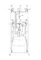
図1に示すように、この実施の形態に係る車両には、車体前端部にスキャン式レーザレーダ11が備えられていると共に、このレーザレーダ11からの検出信号を受けて、当該車両前方に存在する障害物の自車(当該車両)に対する距離や、方位ないし位置、及び移動速度、移動方向等の物体データを算出し、その算出結果から自車の安全運転上最も注意を払うべき対象物の抽出ないし特定、及び車速センサ12で検出される自車速等に基づいて該対象物と自車との間の余裕度の判定等を行なう電子制御ユニット(ECU)10が備えられている。
【0027】
そして、この電子制御ユニット10は、上記対象物に関する物体データをドライバーに対して提供する情報として、運転席前方に配置された例えば液晶画面等でなるナビゲーションシステムと兼用の又は専用のヘッドアップディスプレイ13に余裕度等に応じて変化させて表示し、また、キャビン内前方左右に配置されたスピーカ14a,14bから同じく余裕度等に応じてドライバーに対して警報音を発出し、さらには、該対象物ないし後続車両等に対しても同じく余裕度等に応じて自車の存在をクラクション15やヘッドライト16,16、あるいはハザードランプ17…17等の報知手段を用いて知らしめるようになっている。
【0028】
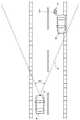
ここで、上記レーザレーダ11は、図2に示すように、レーダ波Hを自車Aの前方に向けて、全スキャン領域が46°、垂直方向視野が2°、水平方向瞬時視野が0.06°等の設定条件で走査、発信し、その反射波を感知するもので、例えば同図に示すように、自車Aの進行方向の前方右側の駐車車両Bや、そのすぐ後ろを横断する歩行者C等の各物体は、電子制御ユニット10の画像処理において、図3に示すように、それぞれ多数の反射波の一群としてとらえられ、その一群の反射波の一塊が個々の各物体として認識、検出される。
【0029】
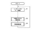
次に、この電子制御ユニット10が行なう具体的制御動作の一例を図4に示すメインフローに従って説明する。
【0030】
すなわち、まずステップS1で上記レーザレーダ11から獲得した撮像データは画像処理されて個々の物体が検出されたうえで、各物体が障害物となり得べき車両なのか人なのか、あるいは道路沿いのリフレクタやガードレール、街路灯なのかといったような物体の識別処理が行なわれる(ステップS2)。この実施の形態においては、道路沿いの固定静止物等が除かれ、車両や人等の可動交通物だけが障害物として識別される。なお、このような物体識別処理の手法は一般に周知なものである。
【0031】
ステップS3では、識別された各障害物の物体データが算出される。この物体データ算出処理は図5に示すフローに従って行なわれ、まず、ステップS31で物体番号nを1とする。つまり、上記ステップS2で障害物と識別された物体は所定の規則に従って番号付けされており、その第1番目の物体を指定するのである。そして、以下のステップS32〜S37で、障害物と識別された各物体について、それぞれ、縦方向の距離(自車の進行方向においての自車と物体との間の距離)Dy、横方向の距離(自車の進行方向と垂直な方向においての自車と物体との間の距離)Dx、縦方向の速度(縦方向距離Dyを時間微分して得られる自車の進行方向においての移動速度)Vy、横方向の速度(横方向距離Dxを時間微分して得られる自車の進行方向と垂直な方向においての移動速度)Vxを算出する。
【0032】
なお、このような物体データの算出の手法も一般に周知なものであり、例えば、図3に示したように、自車位置を原点(0,0)とする各障害物n1,n2,…,のX−Y座標(Xn1,Yn1),(Xn2,Yn2),…,に基づいて行なわれる。ここで、図3では、横断歩行者Cが物体番号1(n1)と、駐車車両Bが物体番号2(n2)とされている。また、この場合、駐車車両B(n2)は停止しているから縦横の速度Vy、Vxは0となり、一方、歩行者C(n1)は、自車の進行方向に対して略垂直に向って右側から左方向に矢印aのように横断しているものとすると、横移動速度Vxだけが求められ、縦移動速度Vyは小さな値となる。さらに、この横移動速度Vx(X座標の値の変化)からその横移動方向が求められる。
【0033】
ステップS4では、上記物体データに基づいて、今後自車が走行していくうえで運転上最も注意すべき対象物が抽出される。この実施の形態においては、横移動速度Vxのみが有意な値に算出され、縦移動速度Vyが小さな値に算出された障害物、つまり自車の進行方向の前方を横切る動きをする障害物を対象物として特定し、特に、そのなかでも横移動速度Vxがおよそ0.6〜1.0m/秒のもの、つまり横移動速度Vxが平均的歩行速度に近いものを対象物として特定し、さらに、そのなかでも縦方向の距離Dyが最も小さい値のもの、つまり自車の進行方向の前方で最も接近しているものを対象物として特定する。図2、図3における上記設例では、駐車車両Bの後ろの横断歩行者Cが対象物として抽出、特定されることになる。
【0034】
ステップS5では、その対象物と自車との間の余裕度が判定される。この余裕度判定処理は図6に示すフローに従って行なわれ、まず、ステップS51で対象物までの距離I、つまり縦方向距離Dyあるいは(Dy2+Dx2)1/2と、自車と対象物との間の相対速度Sと、自車速Vとを入力する。なお、ここで相対速度Sも一般に周知な手法で求められるが、上記設例のように、横断歩行者が自車の進行方向に対して略垂直に横断していて、その縦移動速度Vyが略0であれば、その相対速度Sは略自車速Vに等しくなる。
【0035】
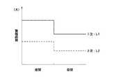
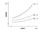
次いで、ステップS52で、1次警報距離L1及び2次警報距離L2を設定する。ここで、電子制御ユニット10のメモリには、図7〜図10に示すように、それぞれ自車速V、相対速度S、路面摩擦係数、時間帯をパラメータとする1次警報距離L1及び2次警報距離L2の特性が格納されており、該特性に各パラメータの実測値や算出値あるいは走行時間帯をあてはめることにより上記警報距離L1,L2を割り出すのである。
【0036】
その場合に、1次警報距離L1及び2次警報距離L2共に、自車速Vが大きくなるほど長くなり、相対速度Sが大きくなるほど長くなり、路面摩擦係数が小さくなるほど長くなり、夜間は昼間より長くなるように設定される。また、いかなる場合においても、1次警報距離L1は2次警報距離L2よりも大きい値に設定され、且つ、いかなる場合においても、1次警報距離L1及び2次警報距離L2共に、上記各条件の組合せの下における制動距離よりも長くなるように設定される。
【0037】
なお、走行時間帯、つまり夜間か昼間かは例えばヘッドライトがONされているかどうかにより判定できる。また、路面摩擦係数の大小を例えばワイパーがONされているかどうかにより判定するようにし、その場合に、路面摩擦係数をパラメータとする警報距離L1,L2の特性をワイパーがONのときに大きく、OFFのときに小さく二段階に変化するように(図10の時間帯による特性のように)設定してもよい。さらには、ワイパーの動作速度が速くなるほど警報距離L1,L2が多段階に大きくなるように設定してもよい。
【0038】
次いで、ステップS53で、対象物までの距離Iが1次警報距離L1よりも短いか否かを判定する。つまり、対象物が自車の1次警報距離L1以内にあるかどうかを判定するのである。そして、YESの場合はステップS54で1次警報フラグF1を1にセットし、NOの場合はステップS55で0にリセットする。
【0039】
1次警報フラグF1を1にセットしたときは、次いで、ステップS56で、対象物までの距離Iが2次警報距離L2よりも短いか否かを判定する。つまり、対象物が1次警報距離L1よりも短い2次警報距離L2以内にあるかどうかを判定するのである。そして、YESの場合はステップS57で2次警報フラグF2を1にセットし、NOの場合はステップS58で0にリセットする。
【0040】
その結果、自車速Vが大きくなるほど、相対速度Sが大きくなるほど、路面摩擦係数が小さくなるほど、また、夜間は昼間に比べて、対象物が自車から離れていてもこれらの警報フラグF1,F2が1にセットされ易くなり、これにより、早めに警報態勢に入ることになる。
【0041】
そして、以下のステップS6,S7,S8で、以上の結果を総合して、ドライバーに対してはディスプレイ13を用いて上記対象物に関する情報が表示され、またスピーカ14a,14bを用いて警報音が発出され、並びに対象物に対してはクラクション15等の報知手段を用いて自車の接近が報知される。
【0042】
まず、ステップS6の表示処理は図11に示すフローに従って行なわれ、まず、ステップS61で1次警報フラグF1が1か否かをみて、YESのときはステップS62に進んで、ここで描画パラメータを対象物の物体データに基づいて設定する。この描画パラメータの設定は、図12に示すように上記ディスプレイ13に表示する描画中における人型をした物体画像の縦横の大きさWgy,Wgx、同じく物体画像の中心Ogのディスプレイ画面中心Oに対する縦横の位置Yg,Xg、対象物の横移動方向を表わす画面中央部の矢印の長さLgを決定するもので、その場合に、物体画像の縦横の大きさWgy,Wgxは対象物の縦方向の距離Dyに応じて変更され、物体画像の縦位置Ygは対象物の縦方向の距離Dyに応じて変更され、物体画像の横位置Xgは対象物の横方向の距離Dxに応じて変更され、矢印の長さLgは対象物の横移動速度Vxに応じて変更される。
【0043】
したがって、対象物が自車に接近しているほど描画中の物体画像が大きく表示され、また、対象物が移動するに伴って描画中の物体画像がその位置を変えて移動方向に移動していくことになり、さらに、対象物の横移動速度が早いほど長い矢印が表示されることになる。
【0044】
これにより、車両前方において進行方向を横切る方向に移動する横断歩行者等が1次警報距離L1以内にいる場合は、上記のような描画がディスプレイ13に表示され、これにより、ドライバーにそのような横断歩行者等が前方に存在するするという情報が提供されて、ドライバーとしては該横断歩行者等の存在を視覚を通じて的確に認知できることになる。
【0045】
そして、その場合に、単に、車両の進行路を横切るような動きをする横断歩行者等が前方に存在するという情報のみがドライバーに提供されるのではなく、併せて、その移動方向、つまり自車の進行方向に向かって右から左方向へ横移動しているのか、あるいは左から右方向へ横移動しているのかといったような情報までもが、画面中の人型をした物体画像の移動や併せて表示される矢印の向き等を通してドライバーに提供されるので、そのような横移動障害物の動き方等も含めてドライバーの安全運転操作が適切に支援されることになる。
【0046】
さらに、併せて、実際の対象物と自車との間の距離及び実際の対象物の自車に対する位置が、それぞれ上記の人型をした物体画像の大きさ及び位置によって画面中に表現され、また実際の対象物の横移動速度が、上記の横移動方向を表わす矢印の長さによって画面中に表現されるので、ドライバーは、横移動障害物の横移動方向の他に、自車が該障害物にどれほど接近しているのか、自車から該障害物がどの方位にあるのか、該障害物がどれほどの速度で横移動しているのかといった種類の情報までも知ることができ、より一層ドライバーの安全運転操作が的確に支援されることになる。
【0047】
次いで、ステップS63では、2次警報フラグF2が1か否かをみて、NOのときはステップS64に進んで、上記のディスプレイ13に表示する描画パターンを1次警報の描画パターンとし、YESのときはステップS65に進んで、2次警報の描画パターンとする。
【0048】
この場合、2次警報の描画パターンとは、描画中の物体画像や矢印等の表示色を最も注意を喚起する赤色に設定したり、それらと背景との表示色を反転させたり、反転を繰り返すことにより物体画像や矢印等と背景とを点滅させたり等することであり、これらを単独で又は組み合わせてディスプレイ表示を行なう。一方、1次警報の描画パターンとは、このような表示方法を採用しない通常表示のことであり、これによって、障害物が自車により近い位置にいる2次警報時は1次警報時に比べてディスプレイ表示が目立ち、ドライバーの注意がより強く喚起されることになる。
【0049】
なお、横移動障害物が1次警報距離L1よりもまだ遠くに存在し、ステップS61で1次警報フラグF1が0のときは、そのままリターンするので、上記のような描画がディスプレイ13に表示されず、したがって、ディスプレイ13には、例えば、他のナビゲーション情報や、エアコン、ステレオ等の作動情報等がそのまま表示される。
【0050】
また、図12は、横断歩行者が右側から左方向に移動する場合の描画を例示するものであり、例えば、横断歩行者が左側から右方向に移動する場合は、人型をした物体画像の向き及び矢印の向きは、逆に右方向を差すように表示される。
【0051】
次に、ステップS7の警報音処理は図13に示すフローに従って行なわれ、まず、ステップS71で1次警報フラグF1が1か否かをみて、YESのときはステップS72に進んで、さらに2次警報フラグF2が1か否かをみる。そして、2次警報フラグF2が1の場合はステップS73でキャビン内の前スピーカ14a,14bから発出する警報音の音量を大とし、2次警報フラグF2が0の場合はステップS74で小とする。
【0052】
次いで、ステップS75で自車に対する対象物の位置を判定して、該対象物が自車の進行方向に向って左側にある場合は、ステップS76で左スピーカ14aのみから、右側にある場合は、ステップS77で右スピーカ14bのみから、それぞれ上記ステップS73又はS74で設定した音量の全音量を出力し、一方、対象物が自車の進行方向の略中央にある場合は、ステップS78で左右の両スピーカ14a,14bから上記ステップS73又はS74で設定した音量の半分の音量づつを出力する。
【0053】
これにより、車両前方において進行方向を横切る方向に移動する横断歩行者等が1次警報距離L1以内にいる場合は、警報音が前スピーカ14a,14bから発出され、これにより、ドライバーにそのような横断歩行者等が前方に存在するするという情報が提供されて、ドライバーとしては該横断歩行者等の存在を聴覚を通じて的確に認知できることになる。
【0054】
そして、その場合に、単に、車両の進行路を横切るような動きをする横断歩行者等が前方に存在するという情報のみがドライバーに提供されるのではなく、併せて、その方位ないし移動方向、つまり自車の進行方向に向かっていずれの方位にいるのか、又は右から左方向へ横移動しているのか、あるいは左から右方向へ横移動しているのかといったような情報までもが、左右の前スピーカ14a,14bを使い分けることによってドライバーに提供されるので、そのような横移動障害物の動き方等も含めてドライバーの安全運転操作が適切に支援されることになる。さらに、横移動障害物が自車に対してより近い位置にいる2次警報時は1次警報時に比べて警報音の音量が強まるので、横移動障害物が自車により接近した場合にはドライバーの注意が一層強く喚起されることになる。
【0055】
次に、ステップS8の対象物に対する報知処理は図14に示すフローに従って行なわれ、ステップS81で2次警報フラグF2が1のときにステップS82において報知手段が作動される。すなわち、前述したように、クラクション15を作動させてホーン音を断続的に出したり、ヘッドライト16,16をパッシングさせたり、ハザードランプ17…17を点灯させたりすることを単独又は組み合わせて行なうのである。これにより、横移動障害物が2次警報距離L2以内にまで自車に接近した場合には、ドライバーに対する運転支援のための障害物情報の提供だけでなく、その対象物である横移動障害物に対しても自車両の接近が知らされるので、ドライバーと障害物との双方において未然に接触を回避する適切な予防処置が促されることになる。また、ハザードランプ17…17が点灯されることによって、対象物への報知と同時に後続車両への注意も促されることになる。
【0056】
次に、上記電子制御ユニット10が行なう具体的制御動作の別の一例を図15に示すメインフローに従って説明する。
【0057】
この制御は、当該車両に自動制動装置が搭載されている場合のもので、上記ステップS8の対象物に対する報知処理に続いて、ステップS9で自動制動処理が追加して行なわれる。
【0058】
その場合に、ステップS5の余裕度判定処理においては、図16に示すように、前述のステップS52に代えて、ステップS52aとして、上記1次警報距離L1及び2次警報距離L2に加えてさらに3次警報距離L3が設定される。
【0059】
この3次警報距離L3は、例えば図17に自車速Vをパラメータとする特性のみを示したが、上記1次警報距離L1及び2次警報距離L2と同様に、自車速Vが大きくなるほど長くなり、相対速度Sが大きくなるほど長くなり、路面摩擦係数が小さくなるほど長くなり、夜間は昼間より長くなるように設定される。また、いかなる場合においても、この3次警報距離L3は2次警報距離L2よりもさらに小さい値に設定され、且つ、いかなる場合においても、この3次警報距離L3も、上記各条件の組合せの下における制動距離よりも長くなるように設定される。
【0060】
そして、さらにステップS5の余裕度判定処理においては、図16に示すように、前述のステップS57,S58に続いて、ステップS59aで、対象物までの距離Iが上記3次警報距離L3よりも短いか否かを判定する。つまり、対象物が2次警報距離L2よりもさらに短い3次警報距離L3以内にあるかどうかを判定するのである。そして、YESの場合はステップS59bで3次警報フラグF3を1にセットし、NOの場合はステップS59cで0にリセットする。
【0061】
そして、ステップS9の自動制動処理は図18に示すフローに従って行なわれ、ステップS91で3次警報フラグF3が1のときにステップS92において自動制動装置(オートブレーキ)が作動される。これにより、横移動障害物が3次警報距離L3以内にまで自車に接近した場合には、自動的にブレーキがかかって該横移動障害物との接触が未然に回避されることになる。
【0062】
なお、自動制動装置が作動したときにはブレーキランプも点灯されるが、この3次警報時の前の2次警報時の段階においてハザードランプ17…17がステップS8の報知処理において点灯されているから、自動制動が働いてブレーキランプが点灯する前から後続車両への注意が喚起されていることになる。
【0063】
次に、ディスプレイ表示の他の形態を例示する。
【0064】
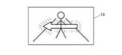
図19は、人物イメージを中央に立たせて、該イメージで表わされる前方障害物の横移動方向を矢印で表示すると共に、該矢印を点滅させて目立たせるものである。そして、距離が詰まってきて警報レベルが1次から2次、3次となるに従い、矢印の表示色を青から黄、赤と変化させたり、点滅速度を上げる等してより緊迫感を出し、警報レベルに応じたかたちでドライバーに情報提供をするようにする。同図は、進行方向に向って右から左に横移動する前方障害物がある場合を例示するが、左から右に横移動する前方障害物がある場合には矢印の向きが逆になる。
【0065】
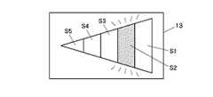
図20は、個々に点灯消灯可能な複数のセグメントS1〜S5を全体形状が三角形となるように並設配置し、該三角形の先細りとなった先端部の向きにより前方障害物の横移動方向を表示すると共に、上記セグメントS1〜S5をその移動方向に順に点灯させていって該移動方向がよりよく分かるようにするものである。そして、距離が詰まってきて警報レベルが1次から2次、3次となるに従い、点灯色を青から黄、赤と変化させたり、点灯の移動速度を上げる等してより緊迫感を出し、警報レベルに応じたかたちでドライバーに情報提供をするようにする。また、画面全体を点滅させるようにし、警報レベルが上がるに従って、その点滅速度を上げるようにしてもよい。同図は、進行方向に向って右から左に横移動する前方障害物があり、セグメントS1〜S5の点灯移動方向も右から左である場合を例示するが、左から右に横移動する前方障害物がある場合には三角形の向きが逆になり、セグメントの点灯移動方向も逆になる。なお、セグメント個数は例示したような5個に限られる必要はない。
【0066】
図21は、移動しようとする方向性が表わされた人物イメージを、前方障害物の横移動方向に図中鎖線で示すように順次移動させて表示するものである。そして、距離が詰まってきて警報レベルが1次から2次、3次となるに従い、人物イメージの表示色を青から黄、赤と変化させたり、人物イメージの移動速度を上げる等してより緊迫感を出し、警報レベルに応じたかたちでドライバーに情報提供をするようにする。また、画面全体を点滅させるようにし、警報レベルが上がるに従って、その点滅速度を上げるようにしてもよい。同図は、進行方向に向って左から右に横移動する前方障害物があり、左から右へ移動しようとする方向性が表わされた人物イメージを左から右に移動させる場合を例示するが、右から左に横移動する前方障害物がある場合には右から左へ移動しようとする方向性が表わされた人物イメージを右から左に移動させる。
【0067】
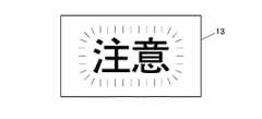
図22は、「注意」という文字表示を、上記図12、又は図19、図20もしくは図21に示したような描画と交互に表示するものである。そして、距離が詰まってきて警報レベルが1次から2次、3次となるに従い、「注意」という文字を「危険」、「警告」等という文字に変化させたり、文字の表示色を青から黄、赤と変化させる等してより緊迫感を出し、警報レベルに応じたかたちでドライバーに情報提供をするようにする。また、画面全体を点滅させるようにし、警報レベルが上がるに従って、その点滅速度を上げるようにしてもよい。
【0068】
なお、車両前方の横移動障害物の該横移動方向が車両の進行方向に向って右から左方向の場合に専用のディスプレイと、左から右方向の場合に専用のディスプレイとを個別に備えるようにしてもよい。
【0069】
【発明の効果】
以上のように本願の第1発明によれば、車両前方に存在する障害物を障害物検出手段で検出したうえで、さらに該障害物の移動方向を移動方向検出手段で検出し、そして、その障害物の移動方向に関する情報を移動情報提供手段でドライバーに提供する場合に、上記移動情報提供手段は、自車の進行方向の前方を横切る動きをする障害物の移動方向に関する情報としては横移動方向に関する情報のみをドライバーに提供するので、車両前方を横切るような動きをする横断歩行者等の存在がドライバーに知らされるのみならず、さらにその移動方向、つまり自車の進行方向に向かって右から左方向へ移動しているのか、あるいは左から右方向へ移動しているのかといったような情報までもが的確にドライバーに提供され、もってそのような横移動障害物の動きも含めて横断歩行者等の存在を明確に認知した適切な運転操作がドライバーに促されることになる。また、移動方向に関する情報としての上記横移動方向に加えて、その横移動方向の移動速度も提供され、しかも、これらの情報が視覚を通じて情報を提供する表示部に表示されるので、ドライバーは、該表示部に表示される情報により、障害物の動きを視覚を通じて的確に認知することができる。
【0070】
また、第2発明によれば、横移動速度がほぼ平均的歩行速度である障害物について横移動方向に関する情報がドライバーに提供される。
【0071】
さらに、第3発明によれば、特に、障害物を表わすイメージが表示部に表示されたうえで、該イメージが移動方向検出手段で検出された横移動方向に移動するので、ドライバーは、そのイメージの移動により障害物の移動方向を一層容易に認知できることになる。
【0072】
これに対して、第4発明によれば、特に、障害物の横移動方向を表わす矢印が表示部に表示されるので、ドライバーは、これによっても、その矢印の向きにより障害物の移動方向を一層容易に認知できることになる。
【0073】
一方、第5発明によれば、障害物を表わすイメージが表示部に表示される場合において、障害物と車両との間の距離が距離検出手段で検出され、また該障害物の車両に対する位置が位置検出手段で検出されたうえで、上記イメージの大きさ及び位置がこれらの検出手段の検出結果に応じてそれぞれ変更されるので、ドライバーは、横移動障害物の横移動方向の他に、該障害物に自車が接近しているのかどうか、該障害物が自車に対してどの方位にいるのかという情報までも、表示部に表示されるイメージから視覚を通じて容易且つ的確に認知できることになる。
【0074】
これに対して、第6発明によれば、障害物の横移動方向を表わす矢印が表示部に表示される場合において、上記矢印の長さが障害物の横移動速度に応じて変更されるので、ドライバーは、横移動障害物の横移動方向の他に、該障害物がどれほどの速度で横移動しているのかという情報までも、表示部に表示される矢印から視覚を通じて容易且つ的確に認知できることになる。
【0075】
また、第7発明によれば、上記第5発明と同じく、障害物と車両との間の距離が距離検出手段で検出され、また該障害物の車両に対する位置が位置検出手段で検出されたうえで、警報音の音量及び発出位置が上記検出手段の検出結果に応じてそれぞれ変更されるので、ドライバーは、横移動障害物に自車が接近しているのかどうか、該障害物が自車に対してどの方位にいるのかという情報を、発出部から発出される警報音に基づいて聴覚を通じて容易且つ的確に認知できることになる。
【0076】
さらに、第8発明によれば、以上のようなドライバーに対する運転支援のための情報提供だけでなく、障害物検出手段で検出された障害物に対しても自車両が接近していることが報知されるので、横移動障害物及びその移動方向等を認知したドライバーの適切な運転操作が促されると共に、該障害物の側においても、自車両との接触を未然に回避する適切な予防処置が促されることになる。
【図面の簡単な説明】
【図1】 本発明の実施の形態に係る車両の障害物警報装置の制御システム図である。
【図2】 同障害物警報装置が機能する交通状況を示す説明図である。
【図3】 同交通状況におけるレーザレーダの画像処理の説明図である。
【図4】 同障害物警報装置の電子制御ユニットが行なう具体的制御動作の一例を示すメインフロー図である。
【図5】 同メインフローの物体データ算出処理動作のフロー図である。
【図6】 同メインフローの余裕度判定処理動作のフロー図である。
【図7】 同余裕度判定処理動作で用いる特性図である。
【図8】 同余裕度判定処理動作で用いる特性図である。
【図9】 同余裕度判定処理動作で用いる特性図である。
【図10】 同余裕度判定処理動作で用いる特性図である。
【図11】 同メインフローの表示処理動作のフロー図である。
【図12】 同表示処理動作の結果ディスプレイに表示される描画の一例を示す説明図である。
【図13】 同メインフローの警報音処理動作のフロー図である。
【図14】 同メインフローの対象物に対する報知処理動作のフロー図である。
【図15】 同障害物警報装置の電子制御ユニットが行なう具体的制御動作の別の一例の特徴部のみを示すメインフロー図である。
【図16】 同メインフローの余裕度判定処理動作の特徴部のみを示すフロー図である。
【図17】 同余裕度判定処理動作で用いる特性図である。
【図18】 同メインフローの自動制動処理動作のフロー図である。
【図19】 ディスプレイ表示の別の一例を示す説明図である。
【図20】 ディスプレイ表示の別の一例を示す説明図である。
【図21】 ディスプレイ表示の別の一例を示す説明図である。
【図22】 ディスプレイ表示の別の一例を示す説明図である。
【符号の説明】
10 電子制御ユニット
11 レーザレーダ
12 車速センサ
13 ディスプレイ
14a,14b スピーカ
15 クラクション
16 ヘッドライト
17 ハザードランプ[0001]
BACKGROUND OF THE INVENTION
The present invention belongs to the technical field of a system for assisting a driver to drive a vehicle safely, and in particular, assists the driver in safe driving by providing the driver with information on obstacles crossing the front of the vehicle. It belongs to the technical field of obstacle alarm devices.
[0002]
[Prior art]
The driver of the vehicle recognizes the surrounding situation mainly visually from the position of the driver's seat through the windshield, the left and right door windows, or through the rear view mirror and the left and right door mirrors, thereby judging the driving course of the vehicle. And speed control, etc., to maintain an appropriate inter-vehicle distance between the front and rear vehicles, smoothly change lanes or merge on highways, or pass through intersections with pedestrian crossings, turn right, turn left, etc. Therefore, in order for the driver to drive the vehicle safely, it is important to know the state of obstacles such as other traveling vehicles and pedestrians around the vehicle. In addition to the information recognized visually, there is known a driving support system configured to detect such an obstacle existing around the vehicle by a device and notify the driver.
[0003]
As this type of driving support system, for example, in Japanese Patent Application Laid-Open No. 7-63846, obstacles in the vicinity of a vehicle are detected by a plurality of ultrasonic sensors provided on the side of the vehicle body. A technique for trying to avoid contact with an object is disclosed.
[0004]
[Problems to be solved by the invention]
By the way, conventionally, this type of driving support system detects an obstacle around the vehicle, but generally, as disclosed in the above publication, the vehicle running in the same direction around the own vehicle. It is intended for stationary objects in close proximity, and tries to avoid contact with subsequent vehicles when changing lanes, rubbing when entering the garage, etc. Are detected in the traveling direction of the own vehicle, or whether there is an obstacle near the own vehicle.
[0005]
However, some obstacles around the vehicle move along the traveling direction of the host vehicle, and not only stationary objects but also move across the traveling direction of the vehicle, such as a crossing pedestrian. At present, there is no proposal for a technique that accurately grasps the existence of such a moving object that moves in the horizontal direction and informs the driver in a clear manner. Of course, it is possible to detect obstacles in front of the vehicle by detecting obstacles around the vehicle, but movement that crosses the traveling direction of the vehicle, which is unique to crossing pedestrians, etc. There is no suggestion of a technique that makes a particular decision as to whether or not to make a decision.
[0006]
Accordingly, an object of the present invention is to provide an obstacle alarm device for accurately detecting the movement of a crossing pedestrian or the like that crosses the front of the vehicle and prompting the driver to perform an appropriate driving operation.
[0007]
[Means for Solving the Problems]
In order to solve the above problems, the present invention uses the following means.
[0008]
First, the invention described in
[0009]
next,Claim 2Described in the following (hereinafter “Second invention" ) Above1st inventionIn the movement information providing means,When providing information on the direction of lateral movement, it is related to the direction of lateral movement of an obstacle that moves across the front in the traveling direction of the vehicle and has a lateral movement speed of 0.6 to 1.0 m / sec. Provide information only to driversIt is characterized by that.
[0010]
Also,Claim 3Described in the following (hereinafter “Third invention" ) Above1st invention or 2nd inventionThe movement information providing means moves the obstacle image detected by the movement direction detecting means on the display section by displaying the image representing the obstacle on the display section in the lateral movement direction detected by the movement direction detecting means. It is characterized by being configured to display the horizontal movement direction.
[0011]
Claim 4Described in the following (hereinafter “Fourth invention" )The first invention or the second inventionThe movement information providing means is configured to display an arrow indicating the lateral movement direction detected by the movement direction detection means on the display unit.
[0012]
Claim 5Described in the following (hereinafter “5th invention" ) AboveFourth inventionA distance detecting means for detecting the distance between the obstacle detected by the obstacle detecting means and the vehicle, and a position detecting means for detecting the position of the obstacle with respect to the vehicle. An arrow indicating the lateral movement direction is displayed on the part, an image representing the obstacle is displayed on the display part, the size of the image representing the obstacle is changed according to the distance detected by the distance detecting means, The position of the image representing the obstacle is changed according to the position detected by the detecting means.
[0013]
Claim 6Described in the following (hereinafter “6th invention" ) AboveFourth inventionThe movement information providing means displays an arrow indicating the horizontal movement direction on the display unit, and according to the horizontal movement speed of the obstacle.the aboveIt is configured to change the length of the arrow.
[0014]
Also,Claim 7Described in the following (hereinafter “7th invention" ) AboveFourth inventionIn the above, there are provided distance detection means for detecting the distance between the obstacle detected by the obstacle detection means and the vehicle, position detection means for detecting the position of the obstacle with respect to the vehicle, and movement information providing means. Has an alarm sound emitting unit that provides information through hearing, displays an arrow indicating the direction of lateral movement on the display unit, and displays an alarm sound emitted from the emitting unit according to the distance detected by the distance detecting means. The sound volume is changed, and the issuing position of the alarm sound from the emitting unit is changed according to the position detected by the position detecting means.
[0015]
further,Claim 8Described in the following (hereinafter “Eighth invention" )the above1st invention or 2nd invention WHEREIN: The obstacle notification means to alert | report the approach of a vehicle with respect to the obstacle detected by the obstacle detection means is provided, It is characterized by the above-mentioned.
[0016]
By using the above-mentioned means, each invention of the present application operates as follows.
[0017]
First, according to the first invention, an obstacle present in front of the vehicle is detected by the obstacle detecting means, and further, the moving direction of the obstacle is detected by the moving direction detecting means, and the movement of the obstacle is detected. When providing information related to the direction to the driver using the movement information providing means, the movement information providing means only provides information related to the lateral movement direction as information relating to the movement direction of the obstacle that moves across the front of the traveling direction of the host vehicle. To the driver, not only the driver is informed of the presence of crossing pedestrians that move across the front of the vehicle, but also from the right to the left in the direction of movement, that is, the direction of travel of the vehicle. Even if it is moving to the right or left, the information such as whether moving from left to right is accurately provided to the driver.The Further, in addition to the lateral movement direction as information relating to the movement direction, the movement speed in the horizontal movement direction is also provided, and since these pieces of information are displayed on a display unit that provides information through vision, the driver can By the information displayed on the display unit, the movement of the obstacle can be accurately recognized through vision.
[0018]
According to the second aspect of the invention, the driver is provided with information on the direction of lateral movement for an obstacle whose lateral movement speed is approximately the average walking speed.
[0019]
further,Third inventionIn particular, since an image representing an obstacle is displayed on the display unit, and the image moves in the lateral movement direction detected by the movement direction detecting means, the driver moves the obstacle by moving the image. It is possible to more easily recognize the moving direction.
[0020]
On the contrary,Fourth inventionIn particular, since the arrow indicating the lateral movement direction of the obstacle is displayed on the display unit, the driver can more easily recognize the movement direction of the obstacle based on the direction of the arrow.
[0021]
on the other hand,5th inventionWhen the image representing the obstacle is displayed on the display unit, the distance between the obstacle and the vehicle is detected by the distance detection means, and the position of the obstacle with respect to the vehicle is detected by the position detection means. In addition, since the size and position of the image are changed according to the detection results of these detection means, the driver can move the vehicle to the obstacle in addition to the lateral movement direction of the lateral movement obstacle. It is possible to easily and accurately recognize through the image from the image displayed on the display section whether or not the vehicle is approaching and information on which direction the obstacle is with respect to the host vehicle.
[0022]
On the contrary,6th inventionAccording to the present invention, when an arrow indicating the lateral movement direction of the obstacle is displayed on the display unit, the length of the arrow is changed according to the lateral movement speed of the obstacle. In addition to the horizontal movement direction, information on how fast the obstacle is moving can be easily and accurately recognized through an arrow displayed on the display unit.
[0023]
Also,7th inventionAccording to the above5th inventionSimilarly, the distance between the obstacle and the vehicle is detected by the distance detecting means, and the position of the obstacle with respect to the vehicle is detected by the position detecting means, and the volume and the emission position of the alarm sound are detected by the detecting means. Therefore, the driver provides information on whether the vehicle is approaching a laterally moving obstacle and in which direction the obstacle is with respect to the own vehicle. Can be recognized easily and accurately through hearing based on the warning sound emitted from the.
[0024]
further,Eighth inventionAccording to the above, in addition to providing information for driving support to the driver as described above, it is notified that the host vehicle is approaching the obstacle detected by the obstacle detection means. Appropriate driving operation of the driver who recognizes the moving obstacle and its moving direction is promoted, and appropriate preventive measures for avoiding contact with the own vehicle are also promoted on the obstacle side. .
[0025]
DETAILED DESCRIPTION OF THE INVENTION
Hereinafter, embodiments of the present invention will be described with reference to the drawings.
[0026]
As shown in FIG. 1, the vehicle according to the present embodiment is provided with a
[0027]
The
[0028]
Here, as shown in FIG. 2, the
[0029]
Next, an example of a specific control operation performed by the
[0030]
That is, first, the imaging data acquired from the
[0031]
In step S3, the object data of each identified obstacle is calculated. This object data calculation processing is performed according to the flow shown in FIG. 5, and first, the object number n is set to 1 in step S31. That is, the object identified as an obstacle in step S2 is numbered according to a predetermined rule, and the first object is designated. Then, in each of the objects identified as obstacles in the following steps S32 to S37, the distance in the vertical direction (the distance between the vehicle and the object in the traveling direction of the vehicle) Dy, the distance in the horizontal direction, respectively. (Distance between own vehicle and object in direction perpendicular to own vehicle traveling direction) Dx, vertical speed (moving speed in own vehicle traveling direction obtained by time differentiation of longitudinal distance Dy) Vy, lateral speed (moving speed in a direction perpendicular to the traveling direction of the vehicle obtained by time differentiation of the lateral distance Dx) Vx is calculated.
[0032]
Such a method for calculating object data is also generally known. For example, as shown in FIG. 3, each of the obstacles n1, n2,. , X-Y coordinates (Xn1, Yn1), (Xn2, Yn2),. Here, in FIG. 3, the crossing pedestrian C is set to object number 1 (n1), and the parked vehicle B is set to object number 2 (n2). In this case, since the parked vehicle B (n2) is stopped, the vertical and horizontal velocities Vy and Vx are 0, while the pedestrian C (n1) is substantially perpendicular to the traveling direction of the own vehicle. Assuming that the vehicle crosses from the right side to the left as indicated by an arrow a, only the lateral movement speed Vx is obtained, and the vertical movement speed Vy becomes a small value. Further, the lateral movement direction is obtained from the lateral movement speed Vx (change in the value of the X coordinate).
[0033]
In step S4, based on the object data, an object that should be most noticed in driving is extracted when the vehicle travels in the future. In this embodiment, an obstacle in which only the lateral movement speed Vx is calculated to a significant value and the longitudinal movement speed Vy is calculated to a small value, that is, an obstacle that moves across the front in the traveling direction of the own vehicle. In particular, the object is specified as an object, in particular, the one having a lateral movement speed Vx of about 0.6 to 1.0 m / sec, that is, the one having a lateral movement speed Vx close to the average walking speed, Among them, the object having the smallest distance Dy in the vertical direction, that is, the object closest to the front in the traveling direction of the own vehicle is specified as the object. 2 and 3, the crossing pedestrian C behind the parked vehicle B is extracted and specified as an object.
[0034]
In step S5, a margin between the object and the own vehicle is determined. This margin determination process is performed according to the flow shown in FIG. 6. First, in step S51, the distance I to the object, that is, the longitudinal distance Dy or (Dy2+ Dx2)1/2And the relative speed S between the host vehicle and the object and the host vehicle speed V are input. Here, the relative speed S is also generally obtained by a well-known method. However, as in the above example, the crossing pedestrian crosses substantially perpendicularly to the traveling direction of the own vehicle, and the vertical movement speed Vy is substantially equal. If it is 0, the relative speed S is substantially equal to the host vehicle speed V.
[0035]
Next, in step S52, the primary alarm distance L1 and the secondary alarm distance L2 are set. Here, in the memory of the
[0036]
In that case, both the primary warning distance L1 and the secondary warning distance L2 become longer as the vehicle speed V becomes larger, become longer as the relative speed S becomes larger, become longer as the road surface friction coefficient becomes smaller, and become longer at daytime than at daytime. Is set as follows. In any case, the primary alarm distance L1 is set to a value larger than the secondary alarm distance L2, and in any case, both the primary alarm distance L1 and the secondary alarm distance L2 It is set to be longer than the braking distance under the combination.
[0037]
Note that the traveling time zone, that is, whether it is nighttime or daytime, can be determined by, for example, whether the headlight is turned on. Further, the magnitude of the road surface friction coefficient is determined by, for example, whether or not the wiper is ON. In this case, the characteristics of the alarm distances L1 and L2 having the road surface friction coefficient as a parameter are large when the wiper is ON and OFF. At this time, it may be set so as to be small and change in two stages (as in the characteristics according to the time zone in FIG. 10). Further, the alarm distances L1 and L2 may be set to increase in multiple stages as the wiper operating speed increases.
[0038]
Next, in step S53, it is determined whether or not the distance I to the object is shorter than the primary warning distance L1. That is, it is determined whether or not the object is within the primary warning distance L1 of the own vehicle. If YES, the primary alarm flag F1 is set to 1 in step S54, and if NO, it is reset to 0 in step S55.
[0039]
When the primary warning flag F1 is set to 1, it is then determined in step S56 whether or not the distance I to the object is shorter than the secondary warning distance L2. That is, it is determined whether or not the object is within the secondary alarm distance L2 shorter than the primary alarm distance L1. If YES, the secondary alarm flag F2 is set to 1 in step S57, and if NO, it is reset to 0 in step S58.
[0040]
As a result, the warning flags F1 and F2 are increased even when the object is further away from the vehicle at night compared to daytime as the vehicle speed V increases, the relative speed S increases, the road surface friction coefficient decreases. Is easily set to 1, so that the alarm state is entered early.
[0041]
Then, in the following steps S6, S7, and S8, the above results are integrated, and the driver is provided with information on the object using the
[0042]
First, the display process in step S6 is performed according to the flow shown in FIG. 11. First, in step S61, it is checked whether or not the primary alarm flag F1 is 1. If YES, the process proceeds to step S62, where the drawing parameters are set. Set based on the object data of the object. As shown in FIG. 12, the drawing parameters are set in the vertical and horizontal sizes Wgy and Wgx of the humanoid object image during drawing displayed on the
[0043]
Therefore, the closer the object is to the vehicle, the larger the object image being drawn, and the object image being drawn changes its position and moves in the moving direction as the object moves. Furthermore, a longer arrow is displayed as the lateral movement speed of the object is faster.
[0044]
As a result, when a crossing pedestrian or the like moving in the direction crossing the traveling direction in front of the vehicle is within the primary warning distance L1, the drawing as described above is displayed on the
[0045]
In this case, the driver is not only provided with information that there is a crossing pedestrian or the like that moves across the path of the vehicle. The movement of a humanoid object image on the screen, such as whether the vehicle is moving laterally from right to left or moving from left to right in the direction of travel In addition, since it is provided to the driver through the direction of the arrow that is displayed together, the safe driving operation of the driver is appropriately supported, including how the laterally moving obstacle moves.
[0046]
In addition, the distance between the actual object and the own vehicle and the position of the actual object with respect to the own vehicle are represented on the screen by the size and position of the humanoid object image, respectively. In addition, since the actual lateral movement speed of the object is represented on the screen by the length of the arrow indicating the lateral movement direction, the driver can move the vehicle in addition to the lateral movement direction of the lateral movement obstacle. You can also know the type of information such as how close you are to the obstacle, where the obstacle is in the direction of the vehicle, and how fast the obstacle is moving laterally. The driver's safe driving operation will be accurately supported.
[0047]
Next, in step S63, it is checked whether or not the secondary alarm flag F2 is 1. If NO, the process proceeds to step S64, and the drawing pattern displayed on the
[0048]
In this case, the secondary alarm drawing pattern is set to the color that draws the most attention, such as the object image being drawn, the arrow, etc., or the display color between them and the background is reversed or repeated. In other words, the object image, the arrow, etc. and the background are blinked, and these are displayed alone or in combination. On the other hand, the primary alarm drawing pattern is a normal display that does not employ such a display method, and as a result, the secondary alarm when the obstacle is closer to the vehicle is compared with the primary alarm. The display will be conspicuous and the driver's attention will be drawn more strongly.
[0049]
If the laterally moving obstacle is still far from the primary alarm distance L1 and the primary alarm flag F1 is 0 in step S61, the process returns as it is, so that the drawing as described above is displayed on the
[0050]
FIG. 12 illustrates the drawing when the crossing pedestrian moves from the right side to the left direction. For example, when the crossing pedestrian moves from the left side to the right direction, the humanoid object image is displayed. The direction and the direction of the arrow are displayed so that the right direction is reversed.
[0051]
Next, the alarm sound processing in step S7 is performed according to the flow shown in FIG. 13. First, in step S71, it is checked whether or not the primary alarm flag F1 is 1. If YES, the process proceeds to step S72 and further secondary. Check whether the alarm flag F2 is 1 or not. If the secondary alarm flag F2 is 1, the volume of the alarm sound emitted from the
[0052]
Next, in step S75, the position of the object with respect to the host vehicle is determined. When the object is on the left side in the traveling direction of the host vehicle, only the
[0053]
As a result, when a crossing pedestrian or the like moving in a direction crossing the traveling direction in front of the vehicle is within the primary warning distance L1, a warning sound is emitted from the
[0054]
And in that case, not only the information that there is a crossing pedestrian etc. that moves in a way that crosses the traveling path of the vehicle is provided to the driver, but also the direction or moving direction, In other words, information such as whether the vehicle is moving in the direction of travel, whether it is laterally moving from right to left, or laterally moving from left to right, Since the
[0055]
Next, the notification process for the object in step S8 is performed according to the flow shown in FIG. 14, and when the secondary alarm flag F2 is 1 in step S81, the notification means is activated in step S82. That is, as described above, the
[0056]
Next, another example of the specific control operation performed by the
[0057]
This control is performed when an automatic braking device is mounted on the vehicle, and the automatic braking process is additionally performed in step S9 following the notification process for the object in step S8.
[0058]
In that case, in the margin determination process of step S5, as shown in FIG. 16, in place of the above-described step S52, step S52a is further replaced with 3 in addition to the primary alarm distance L1 and the secondary alarm distance L2. The next alarm distance L3 is set.
[0059]
For example, FIG. 17 shows only the characteristic using the own vehicle speed V as a parameter, but the third warning distance L3 becomes longer as the own vehicle speed V becomes larger, like the first warning distance L1 and the second warning distance L2. The relative speed S increases as the relative speed S increases, the road friction coefficient decreases as the relative speed S decreases, and is set longer at night than at daytime. In any case, the tertiary alarm distance L3 is set to a value smaller than the secondary alarm distance L2, and in any case, the tertiary alarm distance L3 is also a combination of the above conditions. Is set to be longer than the braking distance at.
[0060]
Further, in the margin determination process of step S5, as shown in FIG. 16, the distance I to the object is shorter than the tertiary alarm distance L3 in step S59a following the above-described steps S57 and S58. It is determined whether or not. That is, it is determined whether or not the object is within the tertiary alarm distance L3 that is shorter than the secondary alarm distance L2. If YES, the tertiary alarm flag F3 is set to 1 in step S59b, and if NO, it is reset to 0 in step S59c.
[0061]
Then, the automatic braking process in step S9 is performed according to the flow shown in FIG. 18. When the tertiary alarm flag F3 is 1 in step S91, the automatic braking device (auto brake) is activated in step S92. As a result, when the laterally moving obstacle approaches the host vehicle within the third warning distance L3, the brake is automatically applied to avoid contact with the laterally moving obstacle.
[0062]
The brake lamp is also turned on when the automatic braking device is activated, but the
[0063]
Next, another form of display display is illustrated.
[0064]
FIG. 19 shows a person image standing in the center, and the lateral movement direction of the front obstacle represented by the image is displayed with an arrow, and the arrow blinks to make it stand out. And as the distance gets tight and the alarm level goes from primary to secondary and tertiary, the display color of the arrow is changed from blue to yellow, red, and the flashing speed is increased, giving a more tense feeling, Provide information to the driver according to the warning level. This figure illustrates the case where there is a forward obstacle that moves laterally from right to left in the direction of travel, but the direction of the arrow is reversed when there is a forward obstacle that laterally moves from left to right.
[0065]
In FIG. 20, a plurality of segments S1 to S5 that can be turned on and off individually are arranged side by side so that the overall shape is a triangle, and the lateral movement direction of the front obstacle is determined by the direction of the tapered tip of the triangle. In addition to displaying, the segments S1 to S5 are sequentially lit in the moving direction so that the moving direction can be better understood. And as the distance gets tight and the alarm level goes from primary to secondary and tertiary, the lighting color is changed from blue to yellow and red, and the moving speed of lighting is increased, etc. Provide information to the driver according to the warning level. Further, the entire screen may be blinked, and the blinking speed may be increased as the alarm level increases. The figure illustrates a case where there is a front obstacle that laterally moves from right to left in the traveling direction, and the lighting movement direction of the segments S1 to S5 is also from right to left, but the front that laterally moves from left to right. When there is an obstacle, the direction of the triangle is reversed, and the lighting movement direction of the segment is also reversed. Note that the number of segments need not be limited to five as illustrated.
[0066]
FIG. 21 is a diagram in which a person image showing the directionality to be moved is sequentially moved and displayed in the lateral movement direction of the front obstacle as indicated by a chain line in the figure. And as the distance gets tighter and the alarm level goes from primary to secondary and tertiary, the person image display color is changed from blue to yellow and red, and the movement speed of the person image is increased. Provide information to the driver in response to the warning level. Further, the entire screen may be blinked, and the blinking speed may be increased as the alarm level increases. This figure exemplifies a case where there is a front obstacle that moves laterally from left to right in the direction of travel, and a person image showing a directionality to move from left to right is moved from left to right. However, when there is a front obstacle that moves laterally from right to left, the person image showing the directionality to move from right to left is moved from right to left.
[0067]
FIG. 22 displays the character display “CAUTION” alternately with the drawing shown in FIG. 12, FIG. 19, FIG. 20, or FIG. Then, as the distance gets tight and the alarm level changes from primary to secondary and tertiary, the word “caution” is changed to characters “danger”, “warning”, etc. Change the color of yellow and red to give the driver a sense of urgency and provide information to the driver according to the warning level. Further, the entire screen may be blinked, and the blinking speed may be increased as the alarm level increases.
[0068]
It should be noted that a dedicated display is separately provided when the lateral movement direction of the laterally moving obstacle in front of the vehicle is right to left from the direction of travel of the vehicle, and a dedicated display is separately provided when the direction is left to right. It may be.
[0069]
【The invention's effect】
As described above, according to the first invention of the present application, after the obstacle present in front of the vehicle is detected by the obstacle detection means, the movement direction of the obstacle is further detected by the movement direction detection means, When the information on the moving direction of the obstacle is provided to the driver by the moving information providing means, the moving information providing means moves laterally as information on the moving direction of the obstacle moving across the front in the traveling direction of the own vehicle. Since only information about the direction is provided to the driver, not only the driver is informed of the presence of crossing pedestrians that move across the front of the vehicle, but also in the direction of movement, that is, the direction of travel of the vehicle. Information such as whether the vehicle is moving from right to left or from left to right is accurately provided to the driver, so that Clearly recognized the proper driving operation of the presence of such cross pedestrian, including the movement of the obstacle is to be prompted to the driver.Further, in addition to the lateral movement direction as information relating to the movement direction, the movement speed in the horizontal movement direction is also provided, and since these pieces of information are displayed on a display unit that provides information through vision, the driver can By the information displayed on the display unit, the movement of the obstacle can be accurately recognized through vision.
[0070]
According to the second aspect of the invention, the driver is provided with information on the direction of lateral movement for an obstacle whose lateral movement speed is approximately the average walking speed.
[0071]
further,Third inventionIn particular, since an image representing an obstacle is displayed on the display unit, and the image moves in the lateral movement direction detected by the movement direction detecting means, the driver moves the obstacle by moving the image. It is possible to more easily recognize the moving direction.
[0072]
On the contrary,Fourth inventionIn particular, since the arrow indicating the lateral movement direction of the obstacle is displayed on the display unit, the driver can more easily recognize the movement direction of the obstacle based on the direction of the arrow.
[0073]
on the other hand,5th inventionWhen the image representing the obstacle is displayed on the display unit, the distance between the obstacle and the vehicle is detected by the distance detection means, and the position of the obstacle with respect to the vehicle is detected by the position detection means. In addition, since the size and position of the image are changed according to the detection results of these detection means, the driver can move the vehicle to the obstacle in addition to the lateral movement direction of the lateral movement obstacle. It is possible to easily and accurately recognize through the image from the image displayed on the display section whether or not the vehicle is approaching and information on which direction the obstacle is with respect to the host vehicle.
[0074]
On the contrary,6th inventionAccording to the present invention, when an arrow indicating the lateral movement direction of the obstacle is displayed on the display unit, the length of the arrow is changed according to the lateral movement speed of the obstacle. In addition to the horizontal movement direction, information on how fast the obstacle is moving can be easily and accurately recognized through an arrow displayed on the display unit.
[0075]
Also,7th inventionAccording to the above5th inventionSimilarly, the distance between the obstacle and the vehicle is detected by the distance detecting means, and the position of the obstacle with respect to the vehicle is detected by the position detecting means, and the volume and the emission position of the alarm sound are detected by the detecting means. Therefore, the driver provides information on whether the vehicle is approaching a laterally moving obstacle and in which direction the obstacle is with respect to the own vehicle. Can be recognized easily and accurately through hearing based on the warning sound emitted from the.
[0076]
further,Eighth inventionAccording to the above, in addition to providing information for driving support to the driver as described above, it is notified that the host vehicle is approaching the obstacle detected by the obstacle detection means. Appropriate driving operation of the driver who recognizes the moving obstacle and its moving direction is promoted, and appropriate preventive measures for avoiding contact with the own vehicle are also promoted on the obstacle side. .
[Brief description of the drawings]
FIG. 1 is a control system diagram of an obstacle alarm device for a vehicle according to an embodiment of the present invention.
FIG. 2 is an explanatory diagram showing a traffic situation in which the obstacle alarm device functions.
FIG. 3 is an explanatory diagram of image processing of a laser radar in the same traffic situation.
FIG. 4 is a main flow diagram showing an example of a specific control operation performed by the electronic control unit of the obstacle alarm device.
FIG. 5 is a flowchart of object data calculation processing operation in the main flow.
FIG. 6 is a flowchart of a margin determination processing operation in the main flow.
FIG. 7 is a characteristic diagram used in the margin determination processing operation.
FIG. 8 is a characteristic diagram used in the margin determination processing operation.
FIG. 9 is a characteristic diagram used in the margin determination processing operation.
FIG. 10 is a characteristic diagram used in the margin determination processing operation.
FIG. 11 is a flowchart of the display processing operation of the main flow.
FIG. 12 is an explanatory diagram showing an example of a drawing displayed on the display as a result of the display processing operation;
FIG. 13 is a flowchart of the alarm sound processing operation of the main flow.
FIG. 14 is a flowchart of a notification processing operation for an object in the main flow.
FIG. 15 is a main flow diagram showing only a characteristic part of another example of a specific control operation performed by the electronic control unit of the obstacle alarm device.
FIG. 16 is a flowchart showing only the characteristic part of the margin determination processing operation of the main flow.
FIG. 17 is a characteristic diagram used in the margin determination processing operation.
FIG. 18 is a flowchart of the automatic braking processing operation of the main flow.
FIG. 19 is an explanatory diagram showing another example of display display.
FIG. 20 is an explanatory diagram showing another example of display display.
FIG. 21 is an explanatory diagram showing another example of display display.
FIG. 22 is an explanatory diagram showing another example of display display.
[Explanation of symbols]
10 Electronic control unit
11 Laser radar
12 Vehicle speed sensor
13 Display
14a, 14b Speaker
15 horn
16 Headlight
17 Hazard lamp
Claims (8)
Translated fromJapanesePriority Applications (1)
| Application Number | Priority Date | Filing Date | Title |
|---|---|---|---|
| JP30798197AJP4389276B2 (en) | 1997-10-21 | 1997-10-21 | Vehicle obstacle warning device |
Applications Claiming Priority (1)
| Application Number | Priority Date | Filing Date | Title |
|---|---|---|---|
| JP30798197AJP4389276B2 (en) | 1997-10-21 | 1997-10-21 | Vehicle obstacle warning device |
Related Child Applications (1)
| Application Number | Title | Priority Date | Filing Date |
|---|---|---|---|
| JP2009158880ADivisionJP2010009607A (en) | 2009-07-03 | 2009-07-03 | Obstacle alarm device for vehicle |
Publications (2)
| Publication Number | Publication Date |
|---|---|
| JPH11115660A JPH11115660A (en) | 1999-04-27 |
| JP4389276B2true JP4389276B2 (en) | 2009-12-24 |
Family
ID=17975474
Family Applications (1)
| Application Number | Title | Priority Date | Filing Date |
|---|---|---|---|
| JP30798197AExpired - LifetimeJP4389276B2 (en) | 1997-10-21 | 1997-10-21 | Vehicle obstacle warning device |
Country Status (1)
| Country | Link |
|---|---|
| JP (1) | JP4389276B2 (en) |
Families Citing this family (52)
| Publication number | Priority date | Publication date | Assignee | Title |
|---|---|---|---|---|
| JP3450189B2 (en)* | 1998-06-16 | 2003-09-22 | ダイハツ工業株式会社 | Pedestrian detection system and control method thereof |
| JP4334686B2 (en)* | 1999-07-07 | 2009-09-30 | 本田技研工業株式会社 | Vehicle image display device |
| JP2001101596A (en)* | 1999-09-27 | 2001-04-13 | Mazda Motor Corp | Display device for vehicle |
| JP4560855B2 (en)* | 1999-09-29 | 2010-10-13 | マツダ株式会社 | Vehicle display device |
| DE10025678B4 (en)* | 2000-05-24 | 2006-10-19 | Daimlerchrysler Ag | Camera-based precrash detection system |
| JP2001341598A (en)* | 2000-06-02 | 2001-12-11 | Auto Network Gijutsu Kenkyusho:Kk | Perimeter monitoring device for vehicles |
| JP3838005B2 (en)* | 2000-08-18 | 2006-10-25 | 日産自動車株式会社 | Vehicle collision prevention device |
| JP2002174526A (en)* | 2000-09-27 | 2002-06-21 | Honda Motor Co Ltd | In-vehicle display device |
| JP4618522B2 (en)* | 2000-11-22 | 2011-01-26 | マツダ株式会社 | Vehicle failure display device |
| JP4639564B2 (en)* | 2001-09-20 | 2011-02-23 | 日産自動車株式会社 | Vehicle crossing fault warning device |
| JP2003291688A (en)* | 2002-04-03 | 2003-10-15 | Denso Corp | Display method, driving support device, program |
| JP3986907B2 (en)* | 2002-07-08 | 2007-10-03 | 本田技研工業株式会社 | Warning device for vehicle |
| JP3948450B2 (en)* | 2003-10-20 | 2007-07-25 | 日産自動車株式会社 | Object detection apparatus and object detection method |
| JP2005212609A (en)* | 2004-01-29 | 2005-08-11 | Denso Corp | Drive supporting device |
| JP4347743B2 (en)* | 2004-05-11 | 2009-10-21 | パイオニア株式会社 | Sound generator, method thereof, program thereof, and recording medium recording the program |
| JP2006031443A (en)* | 2004-07-16 | 2006-02-02 | Denso Corp | Collision avoidance notification system |
| JP4255906B2 (en)* | 2004-12-03 | 2009-04-22 | 富士通テン株式会社 | Driving assistance device |
| JP2006284454A (en)* | 2005-04-01 | 2006-10-19 | Fujitsu Ten Ltd | In-car agent system |
| JP2006327527A (en)* | 2005-05-30 | 2006-12-07 | Honda Motor Co Ltd | Vehicle travel safety device |
| JP4823753B2 (en)* | 2006-04-24 | 2011-11-24 | 本田技研工業株式会社 | Vehicle periphery monitoring device |
| JP5262057B2 (en)* | 2006-11-17 | 2013-08-14 | 株式会社豊田中央研究所 | Irradiation device |
| JP4937844B2 (en)* | 2007-06-12 | 2012-05-23 | 富士重工業株式会社 | Pedestrian detection device |
| JP5041983B2 (en)* | 2007-11-21 | 2012-10-03 | アイシン・エィ・ダブリュ株式会社 | Obstacle warning device, obstacle warning method, and computer program |
| US8009024B2 (en)* | 2008-01-25 | 2011-08-30 | Denso Corporation | Automotive display device showing virtual image spot encircling front obstacle |
| JP5217471B2 (en)* | 2008-02-04 | 2013-06-19 | トヨタ自動車株式会社 | Vehicle object recognition device |
| JP4819919B2 (en) | 2009-04-16 | 2011-11-24 | 本田技研工業株式会社 | Vehicle object detection device |
| JP2010249690A (en)* | 2009-04-16 | 2010-11-04 | Honda Motor Co Ltd | Vehicle object detection device |
| JP2010257298A (en)* | 2009-04-27 | 2010-11-11 | Honda Motor Co Ltd | Vehicle travel safety device |
| WO2011086661A1 (en)* | 2010-01-12 | 2011-07-21 | トヨタ自動車株式会社 | Collision position predicting device |
| US20120176525A1 (en)* | 2011-01-12 | 2012-07-12 | Qualcomm Incorporated | Non-map-based mobile interface |
| US8994823B2 (en) | 2011-07-05 | 2015-03-31 | Toyota Jidosha Kabushiki Kaisha | Object detection apparatus and storage medium storing object detection program |
| WO2013065120A1 (en) | 2011-11-01 | 2013-05-10 | アイシン精機株式会社 | Obstacle alert device |
| CN103733239B (en)* | 2011-11-01 | 2016-05-18 | 爱信精机株式会社 | Obstacle warning device |
| US9082021B2 (en) | 2011-11-01 | 2015-07-14 | Aisin Seiki Kabushiki Kaisha | Obstacle alert device |
| US9396401B2 (en) | 2011-11-01 | 2016-07-19 | Aisin Seiki Kabushiki Kaisha | Obstacle alarm device |
| WO2013065121A1 (en) | 2011-11-01 | 2013-05-10 | アイシン精機株式会社 | Obstacle alert device |
| US9393908B2 (en) | 2011-11-01 | 2016-07-19 | Aisin Seiki Kabushiki Kaisha | Obstacle alarm device |
| JP5861449B2 (en)* | 2011-12-26 | 2016-02-16 | アイシン精機株式会社 | Obstacle alarm device |
| WO2014024294A1 (en)* | 2012-08-09 | 2014-02-13 | トヨタ自動車 株式会社 | Warning device for vehicle |
| WO2014174637A1 (en)* | 2013-04-25 | 2014-10-30 | トヨタ自動車株式会社 | Drive assist device, and drive assist method |
| JP5740717B2 (en)* | 2013-07-05 | 2015-06-24 | 株式会社ユピテル | Electronic device and program |
| KR101470189B1 (en)* | 2013-07-09 | 2014-12-05 | 현대자동차주식회사 | Apparatus and Method for Driving Control of Vehicle |
| KR102209794B1 (en)* | 2014-07-16 | 2021-01-29 | 주식회사 만도 | Emergency braking system for preventing pedestrain and emergency braking conrol method of thereof |
| JP6372402B2 (en) | 2015-03-16 | 2018-08-15 | 株式会社デンソー | Image generation device |
| JP6867638B2 (en)* | 2016-07-04 | 2021-04-28 | 株式会社明電舎 | Sewerage monitoring system and sewerage monitoring program |
| JP6815840B2 (en)* | 2016-11-16 | 2021-01-20 | 株式会社デンソーテン | Radar device and target detection method |
| KR102322854B1 (en)* | 2017-03-13 | 2021-11-08 | 현대자동차주식회사 | Apparatus and method for detecting moving object using ultrasonic sensor, and alarming system thereof |
| CN108303711A (en)* | 2017-12-19 | 2018-07-20 | 深圳市海梁科技有限公司 | A kind of reflecting strips and intelligent automobile laser radar detecting system |
| JP2018167834A (en)* | 2018-07-16 | 2018-11-01 | 株式会社デンソー | Image forming apparatus |
| WO2021064938A1 (en)* | 2019-10-03 | 2021-04-08 | 三菱電機株式会社 | Display control device, display system, and display control method |
| US11772555B2 (en)* | 2019-10-07 | 2023-10-03 | Hyundai Motor Company | Vehicle and method of providing surrounding information thereof |
| JP7308465B2 (en)* | 2020-04-10 | 2023-07-14 | エイディシーテクノロジー株式会社 | In-vehicle image display device and vehicle |
- 1997
- 1997-10-21JPJP30798197Apatent/JP4389276B2/ennot_activeExpired - Lifetime
Also Published As
| Publication number | Publication date |
|---|---|
| JPH11115660A (en) | 1999-04-27 |
Similar Documents
| Publication | Publication Date | Title |
|---|---|---|
| JP4389276B2 (en) | Vehicle obstacle warning device | |
| JP2010009607A (en) | Obstacle alarm device for vehicle | |
| CN102264569B (en) | Integrated visual display system | |
| JP2020093766A (en) | Vehicle control device, control system, and control program | |
| JP5751423B2 (en) | Driving assistance device | |
| JP2003118523A (en) | Vehicle approach notification device | |
| JP2019511066A (en) | Method for controlling the automatic display of a pictogram indicating the presence of an obstacle in front of a vehicle | |
| JP2008269580A (en) | Information providing device for vehicle | |
| CN114572232B (en) | Attention assistance for dynamic blind spots that follow the driver's state while driving | |
| JP3915200B2 (en) | Vehicle obstacle warning device | |
| KR20230074481A (en) | Information processing device, information processing method, program and projection device | |
| JP2009282564A (en) | Warning device for vehicle | |
| CN113602276A (en) | Automobile intelligent auxiliary driving method and system based on LiFi signal interaction | |
| CN115723663A (en) | Danger notification method, danger notification device, and non-transitory storage medium | |
| JP4462895B2 (en) | On-vehicle object recognition system and driving support system using the same | |
| KR102338221B1 (en) | Auxiliary Traffic Light for Preventing Accident in Blind Spot | |
| JP2013032082A (en) | Vehicle display device | |
| JP2005011252A (en) | Information providing device for vehicle | |
| CN104641404A (en) | alarm system | |
| KR102353084B1 (en) | A Safety signage for traffic lights at crosswalks | |
| KR101491177B1 (en) | Night view system and control method thereof | |
| JP2003104148A (en) | Control device of vehicle | |
| JP2019204402A (en) | Obstacle display device and lightning fixture system for vehicle | |
| CN109887334A (en) | Vehicle drive assist system and method | |
| JPH08273098A (en) | Collision prevention device |
Legal Events
| Date | Code | Title | Description |
|---|---|---|---|
| A621 | Written request for application examination | Free format text:JAPANESE INTERMEDIATE CODE: A621 Effective date:20040816 | |
| A977 | Report on retrieval | Free format text:JAPANESE INTERMEDIATE CODE: A971007 Effective date:20070316 | |
| A131 | Notification of reasons for refusal | Free format text:JAPANESE INTERMEDIATE CODE: A131 Effective date:20070403 | |
| A521 | Written amendment | Free format text:JAPANESE INTERMEDIATE CODE: A523 Effective date:20070601 | |
| A131 | Notification of reasons for refusal | Free format text:JAPANESE INTERMEDIATE CODE: A131 Effective date:20080115 | |
| A521 | Written amendment | Free format text:JAPANESE INTERMEDIATE CODE: A523 Effective date:20080313 | |
| A131 | Notification of reasons for refusal | Free format text:JAPANESE INTERMEDIATE CODE: A131 Effective date:20090507 | |
| RD03 | Notification of appointment of power of attorney | Free format text:JAPANESE INTERMEDIATE CODE: A7423 Effective date:20090618 | |
| A521 | Written amendment | Free format text:JAPANESE INTERMEDIATE CODE: A523 Effective date:20090703 | |
| TRDD | Decision of grant or rejection written | ||
| A01 | Written decision to grant a patent or to grant a registration (utility model) | Free format text:JAPANESE INTERMEDIATE CODE: A01 Effective date:20090915 | |
| A01 | Written decision to grant a patent or to grant a registration (utility model) | Free format text:JAPANESE INTERMEDIATE CODE: A01 | |
| A61 | First payment of annual fees (during grant procedure) | Free format text:JAPANESE INTERMEDIATE CODE: A61 Effective date:20090928 | |
| FPAY | Renewal fee payment (event date is renewal date of database) | Free format text:PAYMENT UNTIL: 20121016 Year of fee payment:3 | |
| R150 | Certificate of patent or registration of utility model | Free format text:JAPANESE INTERMEDIATE CODE: R150 | |
| FPAY | Renewal fee payment (event date is renewal date of database) | Free format text:PAYMENT UNTIL: 20131016 Year of fee payment:4 | |
| EXPY | Cancellation because of completion of term |