JP4388203B2 - Combined electromagnetic actuator device - Google Patents
Combined electromagnetic actuator deviceDownload PDFInfo
- Publication number
- JP4388203B2 JP4388203B2JP2000152065AJP2000152065AJP4388203B2JP 4388203 B2JP4388203 B2JP 4388203B2JP 2000152065 AJP2000152065 AJP 2000152065AJP 2000152065 AJP2000152065 AJP 2000152065AJP 4388203 B2JP4388203 B2JP 4388203B2
- Authority
- JP
- Japan
- Prior art keywords
- movable
- electromagnetic actuator
- actuator device
- magnet
- yoke
- Prior art date
- Legal status (The legal status is an assumption and is not a legal conclusion. Google has not performed a legal analysis and makes no representation as to the accuracy of the status listed.)
- Expired - Fee Related
Links
- 239000002131composite materialSubstances0.000claimsdescription25
- 230000007246mechanismEffects0.000claimsdescription13
- 125000006850spacer groupChemical group0.000claimsdescription10
- 230000002093peripheral effectEffects0.000claimsdescription8
- 238000006243chemical reactionMethods0.000claimsdescription7
- 210000000078clawAnatomy0.000claimsdescription7
- 239000000696magnetic materialSubstances0.000claimsdescription7
- 229920003002synthetic resinPolymers0.000claimsdescription3
- 239000000057synthetic resinSubstances0.000claimsdescription3
- 230000009471actionEffects0.000claimsdescription2
- 230000003993interactionEffects0.000claimsdescription2
- 230000004907fluxEffects0.000description12
- 230000004044responseEffects0.000description5
- 238000000429assemblyMethods0.000description3
- 230000000712assemblyEffects0.000description3
- 230000008859changeEffects0.000description3
- XEEYBQQBJWHFJM-UHFFFAOYSA-NIronChemical compound[Fe]XEEYBQQBJWHFJM-UHFFFAOYSA-N0.000description2
- 238000010586diagramMethods0.000description2
- 230000000694effectsEffects0.000description2
- 230000006870functionEffects0.000description2
- 239000006247magnetic powderSubstances0.000description2
- 230000000149penetrating effectEffects0.000description2
- 238000005070samplingMethods0.000description2
- 229910001335Galvanized steelInorganic materials0.000description1
- 230000008878couplingEffects0.000description1
- 238000010168coupling processMethods0.000description1
- 238000005859coupling reactionMethods0.000description1
- 238000002474experimental methodMethods0.000description1
- 239000008397galvanized steelSubstances0.000description1
- 230000006872improvementEffects0.000description1
- 239000011810insulating materialSubstances0.000description1
- 229910052742ironInorganic materials0.000description1
- 239000000463materialSubstances0.000description1
- 238000000034methodMethods0.000description1
- 230000009467reductionEffects0.000description1
- 229920005989resinPolymers0.000description1
- 239000011347resinSubstances0.000description1
- 239000013585weight reducing agentSubstances0.000description1
- 238000004804windingMethods0.000description1
Images


Classifications
- H—ELECTRICITY
- H01—ELECTRIC ELEMENTS
- H01F—MAGNETS; INDUCTANCES; TRANSFORMERS; SELECTION OF MATERIALS FOR THEIR MAGNETIC PROPERTIES
- H01F7/00—Magnets
- H01F7/06—Electromagnets; Actuators including electromagnets
- H01F7/08—Electromagnets; Actuators including electromagnets with armatures
- H01F7/16—Rectilinearly-movable armatures
- H01F7/1607—Armatures entering the winding
- H01F7/1615—Armatures or stationary parts of magnetic circuit having permanent magnet
- H—ELECTRICITY
- H01—ELECTRIC ELEMENTS
- H01F—MAGNETS; INDUCTANCES; TRANSFORMERS; SELECTION OF MATERIALS FOR THEIR MAGNETIC PROPERTIES
- H01F7/00—Magnets
- H01F7/06—Electromagnets; Actuators including electromagnets
- H01F7/08—Electromagnets; Actuators including electromagnets with armatures
- H01F7/121—Guiding or setting position of armatures, e.g. retaining armatures in their end position
- H01F7/122—Guiding or setting position of armatures, e.g. retaining armatures in their end position by permanent magnets
Landscapes
- Physics & Mathematics (AREA)
- Electromagnetism (AREA)
- Engineering & Computer Science (AREA)
- Power Engineering (AREA)
- Reciprocating, Oscillating Or Vibrating Motors (AREA)
- Moving Of Heads (AREA)
- Moving Of The Head To Find And Align With The Track (AREA)
- Connection Of Motors, Electrical Generators, Mechanical Devices, And The Like (AREA)
Description
Translated fromJapanese【0001】
【発明の属する技術分野】
本発明は軸方向にリニア動作する電磁アクチュエ−タ、特に、外周部にステータヨークを有し、その内部に励磁用コイルと永久磁石とヨークからなる可動部を有する可動磁石型の電磁アクチュエータおよび複合型アクチュエータ装置に関する。
【0002】
【従来の技術】
従来知られている電磁アクチュエータとして、たとえば、情報記憶装置の情報読み/書き用ヘッドの駆動に用いられ、ヘッドを直接的に直線駆動または回転駆動させて記録媒体上の適切なトラック上に位置決めさせながら記録媒体から情報を読み/書きする可動コイル型のアクチュエータがある。このアクチュエータはVCM(Voice Coil Motor)と呼ばれ、磁界と直角方向成分のコイルに電流を流すことによって生ずるフレミング左手の法則による電磁力によりコイル部に取り付けたヘッドを駆動するアクチュエータであり、直線領域(移動距離は10mm程度)または回転領域(回転角度は90度程度)内でフィードバック制御技術を用いて高精度の位置決め制御ができる。
【0003】
もう1つの電磁アクチュエータは、安価な2相クローポール型ステッピングモータを用いたもので、モータ軸にリードスクリューを切り、モータの回転に伴ってこのスクリューを介して取り付けられたヘッドが直線運動する方式のアクチュエータである。
【0004】
【発明が解決しようとする課題】
ところが上述した可動コイル型(VCM型)アクチュエータには次のような欠点がある。
(1)移動範囲が広いので、磁石とコイルのエアギャップ長を狭く設定できない。従って、エアギャップの磁束密度を高く設定できない。
(2)高性能磁石を使用しないと必要な推力(電磁力)が出せない。
(3)可動部がコイルであるので巻数を稼ぐことが難しい。従って形状が大きくならざるを得ない。
(4)可動部のコイルに給電しなければならないので、高価な給電ハーネスが必要となる。
(5)移動範囲が広いので、可動部の質量を同じとすると、大きな推力を発生させないと同等の周波数応答性が確保できない。
(6)VCMは、磁気回路を密閉構造にできないので、外部への漏洩磁束が大きい。
(7)漏洩磁束が低減できないので、磁気記憶装置に用いた場合、装置の読み出し/書き込みの信頼性に問題を残す。
等の問題があり、磁気記録装置への流用には大きな制約条件となっていた。また、上記の理由から何と言ってもコストが下がらない欠点もある。
【0005】
一方、2相クローポール型ステッピングモータを用いたアクチュエータには次のような問題がある。
(1)回転運動を直線運動に変換するスクリュー等の機械的な変換機構が必要である。
(2)直結式ではないので性能(高速性かつ高分解能)に限界がある。
(3)駆動源が開ループ制御を前提としたステッピングモータであるので、連続的な位置決めは不可能であり、位置決めの分解能にも限界がある。特に、分解能は現状では精々100μm程度までである。
(4)一般的には開ループ制御であり、閉ループ制御には向いていない。
【0006】
本発明は、VCM型アクチュエータの欠点である可動コイル型構造に係る給電に伴う問題や、漏洩磁束に纏わる問題を解決し、安価で高性能(高速且つ高分解能)な電磁アクチュエータおよびその応用装置である複合型電磁アクチュエータ装置を提供することを目的とする。
【0007】
【課題を解決するための手段】
本発明は上記の目的を達成するために、電磁アクチュエータとステッピングモータとが回転軸を共有して配置され、前記ステッピングモータによる回転軸の回転運動を直線運動に変換する変換機構を有し、前記電磁アクチュエータにより前記回転軸が直線運動する複合型電磁アクチュエータ装置において、前記ステッピングモータの背後に同軸に前記電磁アクチュエータを配置し、前記ステッピングモータは2相クローポール型ステッピングモータからなり、前記電磁アクチュエータは軟磁性材からなる中空のステータヨークの内周側に2組のコイルを軸心を合わせて軸方向に配置してなる固定部と、前記コイルの内部に微小エアギャップを介して軸方向に可動自在に配置された可動磁石と可動ヨークとから成る可動部とを備え、前記可動磁石が発生する磁界と前記コイルに流れる電流との相互作用によって前記可動部が軸方向に移動する構成であって、前記電磁アクチュエータのステータヨークは非磁性のスペーサを介して前記クローポール型ステッピングモータの背後に組み付けられ、前記ステッピングモータによる粗調はオープンループで行われ、前記電磁アクチュエータによる微調はクローズドループで行われることを特徴とする。
【0008】
本発明においては、2組のコイルの一方に流す電流の向きを他方に流す電流の向きと逆にした。
【0009】
本発明においては、2組のコイルの各々がほぼ同一形状の別々の合成樹脂製ボビンに巻回され、コイルを巻回した2組のボビンがステ−タヨークの内部に軸方向に所定の距離離間して配置されるようにした。
【0010】
本発明においては、固定部のステータヨークは中空円筒でありかつ2組のコイルの各々は共に円筒状ボビンに巻回されたリング状コイルであり、可動部は中心に支持軸を有しかつ可動ヨークは固定部の2組のコイルと相互に電磁作用を及ぼし合う位置にあり、前記ステ−タヨークの軸方向両端面には各々軸受機構を有する一対のフランジが配設され、該軸受機構により前記支持軸を軸方向に移動自在に保持するようにした。
【0011】
本発明においては、可動部の可動磁石は、軸方向にN、S2極に着磁された少なくとも1個以上の柱状または中空状の磁石から成り、可動ヨークを前記可動磁石のN、S磁極面に各々当設させたほぼ同形状の一対の軟磁性体ヨークで構成した。
【0012】
本発明においては、可動部の可動ヨークを1個以上の柱状または中空状の軟磁性体で構成し、可動磁石を前記可動ヨークの軸方向両端面に各々当設したぼぼ同形状の一対の磁石で構成し、該一対の磁石は中心部と外周部で極性が異なる2極に着磁しかつ一方の磁石の外周部と他方の磁石の外周部は互いに逆極性に着磁するようにした。
【0013】
本発明においては、可動部の可動磁石の外径寸法を可動ヨークの外径寸法より小さくした。また逆に可動部の可動ヨークの外径寸法を可動磁石の外径寸法より小さくした。
【0014】
本発明においては、可動部の軸方向の移動量を1.0mm以下とした。
【0015】
本発明においては、前記ボビンはつば部を備え、該つば部には端子台が一体に形成され、該端子台には前記コイルの端末が絡げられるコイル絡げ用端子が植設されており、前記電磁アクチュエータのステータヨークの両端縁には前記ボビンの端子台を受け入れる切欠きが形成されていることを特徴とする。
【0016】
本発明においては、前記非磁性のスペーサの厚さが前記電磁アクチュエータのステータヨークの厚さの1.0倍以上であることを特徴とする。
【0018】
本発明による複合型電磁アクチュエータ装置は、情報記憶装置の記録メディアのトラック位置決め用アクチュエータとして用いるのが好ましい。
【0020】
【発明の実施の形態】
以下に、本発明を図面を参照して説明する。
【0021】
図1は本発明による電磁アクチュエータの第1の実施の形態を軸方向に分解して示す斜視図である。電磁アクチュエータ100は、大きく分けて、固定部1と、可動部2と、前フランジ3および後フランジ4から構成されている。
【0022】
固定部1は、軟磁性体(たとえば、亜鉛メッキ鋼板、純鉄、または軟磁性粉末を含有した樹脂あるいは軟磁性体粉末を焼き固めた焼成物)で作られた円筒状のステータヨーク11の内部に2つの同じ円筒状のコイル組立体12と13を軸方向に重ねて配設して構成されている。コイル組立体12および13は同じ構成であり、合成樹脂のような絶縁性材料で作られた円筒状ボビン12aおよび13aにそれぞれコイル12bおよび13bを巻回したものである。ボビン12aおよび13aのつば部には端子台12cおよび13cがそれぞれ一体的に形成され、その端子台12cおよび13cにはそれぞれコイル絡げ用端子12dおよび13dが埋め込まれている。このコイル絡げ用端子12dおよび13dにコイル12bおよび13bの端末が絡げられる。ステ−タヨーク11の上縁および下縁には、ボビン12aおよび13aをこのステ−タヨーク11内に収納したときその端子台12cおよび13cを受入れる切欠き11aおよび11bが形成されている。なお、ボビン12a、13aは後述するように一体型でもよい。
【0023】
可動部2は、中央にあって小径で軸方向にN、S2極に着磁された1個の中空円柱状可動磁石21と、その両側にあって可動磁石21の磁極端面に固定された一対の軟磁性材からなる中空円柱状の可動ヨーク22、23と、これら部材の中心を貫く支持軸24の3つの部分で構成され、全体が固定部1に収納されたコイル組立体12と13の内部に微小空隙を介して軸方向に移動可能に配置される。可動磁石21の外径を可動ヨーク22、23の外径より小さくしたのは、可動磁石21の磁束が直接固定部1のステータヨーク4に漏洩しないようにするためであり、このことにより、漏洩磁束の発生を防ぎ、磁気効率を向上させることができるとともに、可動部2に占める磁石重量の軽量化を図ることができる。結果として、コスト低減および可動部の軽量化による周波数応答の向上にも寄与している。
【0024】
前フランジ3および後フランジ4のそれぞれ中心には支持軸24を支持するための中心穴3aおよび4aが設けられるとともに、前フランジ3には電磁アクチュエータ100を外部に取り付けるための取付け穴3b、3cが設けられている。軸受5と6がフランジ3と4の外側から支持軸24を軸方向に移動可能に支持している。
【0025】
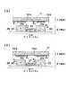
次に電磁アクチュエータの動作および力(推力)発生原理について、図2を用いて説明する。
【0026】
図2は、図1に示した電磁アクチュエータ100の固定部1と可動部2を組立状態で中心軸に関し半断面で示しており、(a)は可動部2が右方向(図中矢印Fで示す方向)に力を受ける場合の動作原理を、また(b)は可動部21が左方向(図中矢印Fで示す方向)に力を受ける場合の動作原理を説明するための図である。説明に直接関係のない軸受、フランジ、ボビンは省略した。なお、図中の参照番号は図1と同一部品については同一符号を用いている。
【0027】
まず図2(a)において、コイル組立体12のコイル12bには紙面下から上に、コイル組立体13のコイル13bには紙面上から下に電流が流れているものとする。可動部2の可動磁石21の磁界については、磁石21のN極→可動ヨーク22→空隙(磁界H1)→コイル12b→ステータヨーク11→コイル13b→空隙(磁界H2)→可動ヨーク23→磁石21のS極で示す磁気回路が形成される。
【0028】
この磁気回路で注目したいのは空隙の磁界H1、H2である。空隙の磁界H1とH2の向きは逆方向であり、磁界の大きさは均一である。つまり、磁界H1は可動ヨーク22からステータヨーク11の向きに、また磁界H2はステータヨーク11から可動ヨーク23の向きであり、これら磁界H1とH2は空隙において大きさが等しく、可動部2が軸方向に移動してもこの空隙中の磁界の強さが不変であることが好ましい。その理由は、電磁力により可動部2が軸方向に移動しても、空隙中での磁界の大きさが変わらなければ、同一のコイル電流値に対して発生する推力は可動部2の位置によらず一定となるからである。このことは本発明による電磁アクチュエータを位置決め機構として用いた場合の制御性(後述)を向上させることになるからである。
【0029】
さて、ここで、リング状のコイル12b、13bに図2(a)に示す方向に電流を流せば、フレミング左手の法則によりコイル12bは矢印F1(図では6個のリング状コイルに働く力の合力として)の方向に力を受けるが、コイル12bはステ−タヨーク112固定されているので、その反作用として可動ヨーク22が逆向きに力F1を受ける。同様にコイル13bは、矢印F2(図では6個のリングコイルに働く力の合力として)の方向に力を受けるが、その反作用として可動ヨーク23が逆向きに力F2を受ける。支持軸24の摩擦力を無視すれば、結果的に可動部2全体は力F=F1+F2の推力を発生し、この力で可動部2は軸方向右方向に移動することになる。
【0030】
一方、コイル12b、13bに図2(b)の方向に電流を流せば、フレミング左手の法則によりコイル12bは矢印F3(図では6個のリングコイルに働く力の合力として)の方向に力を受け、その反作用として可動ヨーク22は逆向きに力F3を受ける。同様にコイル13bは矢印F4(図では6個のリングコイルに働く力の合力として)の方向に力を受け、その反作用として可動ヨーク23は逆向きに力F4を受け、結果的に可動部2全体は軸方向(紙面左向き)の推力F=F3+F4を発生することになる。
【0031】
このように、本発明の電磁アクチュエータは、リング状コイル12b、13bに流す電流の向きとその大きさによって可動部の移動方向並びに発生推力を任意に変えることができる。この電磁アクチュエータをたとえば位置決め閉ループ制御に組み込めば、可動部2を直線運動させながら任意の位置に位置決めすることができる。すなわち、可動部2の現在位置が目標位置に対して図2(a)の左側にあれば、コイル12b、13bに流す電流の向きを逆(図2(b)に示した電流の方向)にして大電流を流して高速で目標位置に近づけ、目標位置に近づいたらコイル電流値を下げて目標位置に停止させるように動作させればよい。万一、目標位置近傍で目標位置を通り過ぎてしまえば、電流の向きを変えて可動部2を引き戻せばよい。
【0032】
このように可動部2の現在位置と目標位置を比較しながら、連続的に電流の向きと値を変えていくことにより可動部2を絶えず目標位置に合致させることができる。
【0033】
図3は図1に示した実施の形態の可動部2の分解斜視図である。
【0034】
中空円柱状可動磁石21は軸方向(矢印Mで示す方向)に上下2極(N極およびS極)に着磁されており、可動磁石21のN極側の磁極面には中空円柱状可動ヨーク22が、またS極側の磁極面には同形状、同寸法の可動ヨーク23が固定されている。支持軸24が可動磁石21と可動ヨーク22、23の中心穴を貫通して可動部全体を保持している。
【0035】
可動磁石21の外径D1は可動ヨーク22、23の外径D2より小さくしてあるが、これは漏洩磁束を低減させる効果がある。その理由は、図2の磁気回路からわかるように、可動磁石21は磁束を軸方向に出来るだけ多く通す必要があり、そのためにはこの部分から固定部1のステ−タヨーク11に飛ぶ、いわゆる漏洩磁束を減らす必要があるからである。そのためには可動磁石21の外径D1を可動ヨーク22、23の外径D2より小さくすることは極めて有効である。それに加えて、可動部2の軽量化により周波数応答性を向上させることができ、高価な磁石材料の使用量も削減できるので、アクチュエータのコストダウンにも効果がある。
【0036】
図4はアクチュエータの可動部の他の実施の形態を示す。
【0037】
この実施の形態においては、中央に軟磁性体から成る小径の可動ヨーク31があって、その両側に2個の可動磁石32、33が配設され、全体の中心に支持軸24が貫通している。上側の可動磁石32は中心穴の周囲をS極に、その外周部をN極に着磁し、下側の可動磁石23は中心穴の周囲をN極に、その外周部をS極に着磁している。可動ヨーク31の外径D1を可動磁石32、33の外径D2より小さくする技術的意味は第1の実施の形態の場合と同じである。
【0038】
このような可動部に対する磁気回路を図5に示した。図中固定部1の構成部分については図2(a)、(b)におけると同じ参照番号で示した。
【0039】
図2(a)および(b)の場合と同様に、可動磁石32、33による磁気回路が矢印で示すように形成されるので、コイル12b、13bに電流を流せば、図2の場合と同様に電磁力を発生し、この電磁力により可動部2は軸方向に動かされる。
【0040】
図6はアクチュエータの可動部のさらに他の実施の形態である。
【0041】
この実施の形態においては、中央に複数個(図示した例では4個)の円柱状磁石体40a、40b、40c、40dから構成された可動磁石40があり、その軸方向両側にそれぞれ軟磁性体から成る可動ヨーク41、42が配設され、全体の中心に支持軸24が貫通している。円柱状磁石体40a、40b、40c、40dは軸方向上下2極(N極およびS極)に着磁されている。この可動部に形成される磁気回路および基本動作は図2を参照して説明したと同じであるので説明は省略する。
【0042】
この実施の形態の特徴は、可動部の重量を低減させることにより応答周波数を上げることができ、磁石の使用量を減らしてコストを低減させることができる点である。
【0043】
なお、可動磁石40を構成する円柱状磁石体の数は4個に限らないし、形状についても円柱形状に限らない。可動磁石40の外径D1が可動ヨーク41、42の外径D2の1/2程度になるように、複数個の円柱状磁石体を均等に配置することが漏洩磁束の点から好ましい。
【0044】
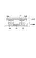
図7は、図1に示した電磁アクチュエータの固定部1と可動部2で構成されるアクチュエータユニットを5個分1本の共通軸上に連結し、全体を1個のステータヨーク内に収納して構成した多段式電磁アクチュエータの半断面を示す。図中、図1と同じ構成部分には同じ参照番号を付し、5個のアクチュエータユニットの同磁構成部分に対しては−1、―2、… ―5を付して示した。
【0045】
可動部の支持軸24には各アクチュエータユニット間に適切な長さのスペーサ50が挿入され、可動部とコイルとの適切な位置関係を確保するようにしている。アクチュエータユニット100−1、100−2、 … 100−5の各々について軸方向の推力が発生する動作は図2および図5を参照して説明したので省略する。このように複数個のアクチュエータユニットを軸方向に連結することにより、各アクチュエータユニットにより発生する推力が合成され、簡単に推力の増大化が図れる。なお、アクチュエータユニットの連結数は5個に限るものではない。
【0046】
図8は本発明による電磁アクチュエータの第2の実施の形態を示し、軸方向に分解した斜視図で示している。図1に示した第1の実施の形態の構成部分に対応する構成部分には図1における参照番号に100を加えて用い、敢えて説明の必要のないものについては説明を省略した。
【0047】
第2の実施の形態による電磁アクチュエータ200は、コイル組立体112とステータヨーク111から成る固定部101と、円柱状の可動磁石121とその両側に配された四角柱状の可動ヨーク122、123の中心に支持軸124を貫通させて構成した可動部102と、前フランジ103および後フランジ104とから構成されている。105、106は軸受、107,108はワッシャである。
【0048】
本実施の形態の特徴は固定部101の構造にある。すなわち固定部101の形状が第1の実施の形態のように円柱状ではなく四角柱状であることと、コイル組立体112のボビン112aが2個ではなく1個で構成されている点である。それにともないコイル組立体の内部に配置される可動部102の形状も四角柱状である。
【0049】
以下に特徴的なコイル組立体112について説明する。
【0050】
コイル組立体112は、樹脂製の2つの巻線部を有する1個のボビン112aと、2組のコイル112b−1、112b−2で構成されている。ボビン112aの中央部にはどて112cが形成されており、このどて112cにより2組のコイル112b−1と112b−2が重ならないように隔離される。ボビン112aの形状はステータヨーク111の形状と整合する四角形であり、ボビン112aの中央にある可動部102を収納する穴も四角形状である。この穴はもちろん第1の実施の形態と同様に円柱形状でもよい。ボビン112aのどて112cの一部には端子台112dが形成され、その端子台112dにはコイル絡げ用端子が埋め込まれている。
【0051】
ステ−タヨーク111は平面展開した軟磁性板を角柱状に仕上げ、その端縁どうしを接合させたものであり、その接合面の中央には、ボビン112のどて112cに形成された端子台112dを受けて絶縁ブッシング(図示せず)を介してコイルを引き出すための角穴111aが形成されている。またステ−タヨーク111の接合面にはロック機構111bが形成されている。
【0052】
この第2の実施の形態は、コイル組立体112を1個のボビン112aで構成できる簡便さがあり、これらの同軸度も精度良く確保できる特徴がある。
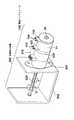
図9は本発明による電磁アクチュエータを利用した複合型アクチュエータ装置を示す。
【0053】
具体的には、開ループで制御される2相クローポール型ステッピングモータをフレームに組み込んだ従来型の位置決め装置300のステッピングモータ310の背後にそれと同軸的に本発明の電磁アクチュエータ100を複合させた複合型アクチュエータ装置である。
【0054】
ステッピングモータ310の回転軸にリードスクリュー320が形成され、電磁アクチュエータ100の支持(可動)軸24はこのリードスクリュー320と同一の軸となっている。電磁アクチュエータ100のステータヨーク11はスッテッピングモータ310との磁気遮蔽の目的で、非磁性のスペーサ330を介してステッピングモータ310の背部に組み付けられている。電磁アクチュエータ100には、ボビン(図示せず)の端子台101、102に設けられた端子103、104から給電される。なお、フレーム340への組付けは、電磁アクチュエータ100に対してスペーサ330を介してステッピングモータ310を組み付けてもよい。
【0055】
電磁アクチュエータ100をステッピングモータ310に組み込むときの注意点は、軸方向に移動する電磁アクチュエータ100の軸方向パーミアンスのバランスを崩さないことである。つまり、電磁アクチュエータ100の一端面側のみに軟磁性体を取り付けないことである。このために電磁アクチュエータ100をステッピングモータ310の背面に取り付ける際、磁気的な結合を切るために非磁性のスペーサ330は充分に厚いものが必要となる。このスペーサ330により安定した電磁アクチュエータ100の動作を確保することができる。なお、実験では、スペーサ330の厚さは電磁アクチュエータ100のステータヨーク11の厚さの1.0倍以上が好ましいことが解った。
【0056】
この複合型電磁アクチュエータ装置はたとえば情報書込み/読取り機構のヘッドの駆動に用いられる。リードスクリュー320の溝を介した移動ピン(図示せず)に保持されたヘッド部(図示せず)はリードスクリュー320の回転に伴って軸方向に移動する。
【0057】
いまヘッド部の位置が目標位置から大きく離れているときは、まずステッピングモータ310で調整し(これを「粗調」といい、高速で且つ離散的な位置制御を行う)し、目標位置の近傍では電磁アクチュエータ100による調整(これを「微調」といい、高精度で且つ連続的な閉ループの位置決め制御を行う)を行う。電磁アクチュエータ100を用いた微調動作は、閉ループで時間に対して連続的またはサンプリングタイムが極めて短い高サンプリングレートで制御を行うことが望ましい。図において、リードスクリュー320の矢印X、Yはリードスクリューの移動方向を示している。矢印Xはステッピングモータ310の動作(粗調)時の回転動作を示し、矢印Yは電磁アクチュエータ100の動作(微調)時の軸方向動作を示し、いずれの動作においてもヘッド部は軸方向に移動するようになっている。
【0058】
上記の実施の形態においては、リードスクリュー320の先端と電磁アクチュエータ100またはステッピングモータ310の端部の2点に軸受を設けた。このことにより軸受スパンを最大長とすることが可能となり、安定した軸受け機構が実現できる。なお、フレーム340に取り付けられるステッピングモータのフランジ350には軸受け機構は設けない。
【0059】
システムの構成にもよるが、電磁アクチュエータ100による微調の範囲は軸方向可動距離にして1.0mm以下が好ましい。その理由は、可動距離が大きくなると、一定の応答周波数まで対応させるためには大きな推力が必要になり、コスト並びに大きさが増大するからである。このような複合型電磁アクチュエータ装置を用いれば、祖調/微調の機能を完全に分離できるので、位置決め装置をトータル的に見て、漏洩磁束が極めて少ない、高速/高精度で且つ安価な位置決め機構が構成できる特徴がある。
【0060】
【発明の効果】
本発明によれば、可動コイル型のアクチュエータの欠点のない簡潔な構成で安価な電磁アクチュエータを提供することができる。また、本発明による電磁アクチュエータを用いた複合型アクチュエータ装置では粗調/微調の機能を完全に分離することができるので、漏洩磁束が少なく、安価で且つ高速/高精度の情報記憶装置のトラック位置決め機構が実現できる。
【図面の簡単な説明】
【図1】本発明による電磁アクチュエータの一実施の形態の分解斜視図である。
【図2】(a)および(b)は本発明による電磁アクチュエータの動作原理を説明する図である。
【図3】図1に示した電磁アクチュエータの可動部の分解斜視図である。
【図4】本発明による電磁アクチュエータの可動部の他の実施例の分解斜視図である。
【図5】図4に示した可動部を用いた電磁アクチュエータの動作原理を説明する図2と同様な図である。
【図6】本発明による電磁アクチュエータの可動部のさらに他の実施例の分解斜視図である。
【図7】本発明による多段式電磁アクチュエータの半断面図である。
【図8】本発明による電磁アクチュエータの第2の実施の形態の分解斜視図である。
【図9】本発明による複合型電磁アクチュエータ装置の一実施の形態の斜視図である。
【符号の説明】
1 固定部
11 ステ−タヨーク
12、13 コイル組立体
12a、13a ボビン
12b、13b コイル
2 可動部
21、40 可動磁石
22、23、41、42 可動ヨーク
24 支持軸
3 前フランジ、4 後フランジ
100 電磁アクチュエータ[0001]
BACKGROUND OF THE INVENTION
The present invention relates to an electromagnetic actuator that linearly operates in an axial direction, and in particular, a movable magnet type electromagnetic actuator having a stator yoke at the outer peripheral portion and a movable portion including an exciting coil, a permanent magnet, and a yoke, and a composite The present invention relates to a mold actuator device.
[0002]
[Prior art]
As a conventionally known electromagnetic actuator, for example, it is used for driving an information reading / writing head of an information storage device, and the head is directly driven linearly or rotationally to be positioned on an appropriate track on a recording medium. However, there is a moving coil type actuator that reads / writes information from a recording medium. This actuator is called VCM (Voice Coil Motor) and is an actuator that drives a head attached to a coil portion by electromagnetic force according to Fleming's left-hand rule that is caused by passing a current through a coil having a component perpendicular to a magnetic field. High-accuracy positioning control can be performed using a feedback control technique within a movement range (about 10 mm) or a rotation region (a rotation angle is about 90 degrees).
[0003]
The other electromagnetic actuator uses an inexpensive two-phase claw pole type stepping motor. The lead screw is cut on the motor shaft, and the head attached via this screw moves linearly as the motor rotates. Actuator.
[0004]
[Problems to be solved by the invention]
However, the moving coil type (VCM type) actuator described above has the following drawbacks.
(1) Since the moving range is wide, the air gap length between the magnet and the coil cannot be set narrow. Therefore, the magnetic flux density of the air gap cannot be set high.
(2) Necessary thrust (electromagnetic force) cannot be produced unless a high-performance magnet is used.
(3) Since the movable part is a coil, it is difficult to earn the number of turns. Therefore, the shape must be large.
(4) Since power must be supplied to the coil of the movable part, an expensive power supply harness is required.
(5) Since the moving range is wide, if the mass of the movable part is the same, an equivalent frequency response cannot be secured unless a large thrust is generated.
(6) Since VCM cannot make a magnetic circuit into a sealed structure, the leakage magnetic flux to the outside is large.
(7) Since the leakage magnetic flux cannot be reduced, there is a problem in the read / write reliability of the device when used in a magnetic storage device.
Therefore, the diversion to the magnetic recording apparatus has been a great constraint. Moreover, there is also a drawback that the cost does not decrease for the above reasons.
[0005]
On the other hand, an actuator using a two-phase claw pole type stepping motor has the following problems.
(1) A mechanical conversion mechanism such as a screw that converts rotational motion into linear motion is required.
(2) The performance (high speed and high resolution) is limited because it is not a direct connection type.
(3) Since the driving source is a stepping motor based on open-loop control, continuous positioning is impossible, and positioning resolution is limited. In particular, the resolution is at most about 100 μm at present.
(4) Generally, it is open loop control and is not suitable for closed loop control.
[0006]
The present invention solves the problems associated with power feeding related to the moving coil structure, which is a drawback of VCM actuators, and the problems associated with leakage magnetic flux, and is an inexpensive and high-performance (high-speed and high-resolution) electromagnetic actuator and its application device. An object of the present invention is to provide a composite electromagnetic actuator device.
[0007]
[Means for Solving the Problems]
In order to achieve the above object, the present inventionA composite type in which an electromagnetic actuator and a stepping motor are arranged so as to share a rotation axis, and has a conversion mechanism for converting the rotation motion of the rotation shaft by the stepping motor into a linear motion, and the rotation shaft linearly moves by the electromagnetic actuator. In the electromagnetic actuator device, the electromagnetic actuator is arranged coaxially behind the stepping motor, the stepping motor is a two-phase claw pole type stepping motor, and the electromagnetic actuator is an inner periphery of a hollow stator yoke made of a soft magnetic material. A fixed portion formed by axially arranging two sets of coils on the side, and a movable magnet and a movable yoke disposed in the coil so as to be movable in the axial direction via a minute air gap. And a magnetic field generated by the movable magnet and flowing in the coil The movable portion moves in the axial direction by interaction with the flow, and the stator yoke of the electromagnetic actuator is assembled behind the claw pole type stepping motor via a non-magnetic spacer, and the stepping motor The coarse adjustment is performed in an open loop, and the fine adjustment by the electromagnetic actuator is performed in a closed loop.
[0008]
In the present invention, the direction of the current flowing through one of the two sets of coils is reversed from the direction of the current flowing through the other.
[0009]
In the present invention, each of the two sets of coils is wound on separate synthetic resin bobbins having substantially the same shape, and the two sets of bobbins wound with the coils are separated from each other by a predetermined distance in the axial direction inside the stator yoke. To be arranged.
[0010]
In the present invention, the stator yoke of the fixed part is a hollow cylinder, and each of the two sets of coils is a ring-shaped coil wound around a cylindrical bobbin, and the movable part has a support shaft at the center and is movable. The yoke is in a position where it exerts an electromagnetic action with the two sets of coils of the fixed portion, and a pair of flanges each having a bearing mechanism are disposed on both end surfaces in the axial direction of the stator yoke. The support shaft is held movably in the axial direction.
[0011]
In the present invention, the movable magnet of the movable part is composed of at least one columnar or hollow magnet magnetized in the N and S2 poles in the axial direction, and the movable yoke is used as the N and S magnetic pole surfaces of the movable magnet. And a pair of soft magnetic yokes having substantially the same shape.
[0012]
In the present invention, the movable yoke of the movable portion is composed of one or more columnar or hollow soft magnetic bodies, and the pair of magnets having substantially the same shape are provided in which the movable magnets are respectively disposed at both axial end surfaces of the movable yoke. The pair of magnets are magnetized to two poles having different polarities in the central part and the outer peripheral part, and the outer peripheral part of one magnet and the outer peripheral part of the other magnet are magnetized to opposite polarities.
[0013]
In the present invention, the outer diameter of the movable magnet of the movable portion is made smaller than the outer diameter of the movable yoke. Conversely, the outer diameter of the movable yoke of the movable part is made smaller than the outer diameter of the movable magnet.
[0014]
In the present invention, the moving amount of the movable portion in the axial direction is set to 1.0 mm or less.
[0015]
In the present invention,The bobbin includes a flange portion, and a terminal block is integrally formed on the flange portion, and a terminal for coil binding, in which the terminal of the coil is wound, is implanted in the terminal block. A notch for receiving the terminal block of the bobbin is formed at both ends of the stator yoke.
[0016]
In the present invention,The thickness of the nonmagnetic spacer is 1.0 times or more the thickness of the stator yoke of the electromagnetic actuator.
[0018]
The composite electromagnetic actuator device according to the present invention is preferably used as a track positioning actuator for a recording medium of an information storage device.
[0020]
DETAILED DESCRIPTION OF THE INVENTION
The present invention will be described below with reference to the drawings.
[0021]
FIG. 1 is a perspective view showing a first embodiment of an electromagnetic actuator according to the present invention exploded in the axial direction. The
[0022]
The
[0023]
The
[0024]
Center holes 3a and 4a for supporting the
[0025]
Next, the operation of the electromagnetic actuator and the principle of generating force (thrust) will be described with reference to FIG.
[0026]
FIG. 2 shows the fixed
[0027]
First, in FIG. 2A, it is assumed that a current flows through the
[0028]
What we want to pay attention to in this magnetic circuit is the magnetic field H of the air gap1, H2It is. Air gap magnetic field H1And H2The direction of is the reverse direction, and the magnitude of the magnetic field is uniform. That is, the magnetic field H1Indicates the direction from the
[0029]
Now, if a current is passed through the ring-shaped
[0030]
On the other hand, if a current is supplied to the
[0031]
Thus, the electromagnetic actuator of the present invention can arbitrarily change the moving direction of the movable part and the generated thrust depending on the direction and magnitude of the current flowing through the ring coils 12b and 13b. If this electromagnetic actuator is incorporated in, for example, positioning closed loop control, the
[0032]
In this way, by continuously changing the direction and value of the current while comparing the current position of the
[0033]
FIG. 3 is an exploded perspective view of the
[0034]
The hollow cylindrical
[0035]
The outer diameter D of the
[0036]
FIG. 4 shows another embodiment of the movable part of the actuator.
[0037]
In this embodiment, there is a small-diameter
[0038]
A magnetic circuit for such a movable part is shown in FIG. In the figure, the components of the fixing
[0039]
As in the case of FIGS. 2A and 2B, the magnetic circuit by the
[0040]
FIG. 6 shows still another embodiment of the movable part of the actuator.
[0041]
In this embodiment, there are a plurality of (four in the illustrated example) cylindrical magnet bodies 40a, 40b, 40c, and 40d in the center, and a
[0042]
The feature of this embodiment is that the response frequency can be increased by reducing the weight of the movable part, and the amount of magnet used can be reduced to reduce the cost.
[0043]
Note that the number of columnar magnet bodies constituting the
[0044]
FIG. 7 shows that the actuator unit composed of the fixed
[0045]
A
[0046]
FIG. 8 shows a second embodiment of the electromagnetic actuator according to the present invention, and is shown in a perspective view exploded in the axial direction. Components corresponding to those in the first embodiment shown in FIG. 1 are used by adding 100 to the reference numerals in FIG. 1, and those that do not need to be described are omitted.
[0047]
The
[0048]
The feature of this embodiment is the structure of the fixing
[0049]
The
[0050]
The
[0051]
The
[0052]
The second embodiment has a feature that the
FIG. 9 shows a composite actuator device using an electromagnetic actuator according to the present invention.
[0053]
Specifically, the
[0054]
A
[0055]
A point to note when incorporating the
[0056]
This composite electromagnetic actuator device is used for driving a head of an information writing / reading mechanism, for example. A head portion (not shown) held by a moving pin (not shown) through the groove of the
[0057]
If the position of the head is far away from the target position, first, the stepping
[0058]
In the above embodiment, bearings are provided at two points, that is, the tip of the
[0059]
Although depending on the system configuration, the range of fine adjustment by the
[0060]
【The invention's effect】
According to the present invention, an inexpensive electromagnetic actuator can be provided with a simple configuration without the disadvantages of a moving coil actuator. Further, in the composite actuator device using the electromagnetic actuator according to the present invention, the coarse / fine adjustment functions can be completely separated, so that the track positioning of the low-speed and high-speed / high-accuracy information storage device with less leakage magnetic flux is possible. The mechanism can be realized.
[Brief description of the drawings]
FIG. 1 is an exploded perspective view of an embodiment of an electromagnetic actuator according to the present invention.
FIGS. 2A and 2B are diagrams illustrating the operating principle of an electromagnetic actuator according to the present invention.
FIG. 3 is an exploded perspective view of a movable portion of the electromagnetic actuator shown in FIG.
FIG. 4 is an exploded perspective view of another embodiment of the movable part of the electromagnetic actuator according to the present invention.
5 is a view similar to FIG. 2 for explaining the operation principle of the electromagnetic actuator using the movable part shown in FIG. 4;
FIG. 6 is an exploded perspective view of still another embodiment of the movable part of the electromagnetic actuator according to the present invention.
FIG. 7 is a half sectional view of a multistage electromagnetic actuator according to the present invention.
FIG. 8 is an exploded perspective view of a second embodiment of an electromagnetic actuator according to the present invention.
FIG. 9 is a perspective view of an embodiment of a composite electromagnetic actuator device according to the present invention.
[Explanation of symbols]
1 fixed part
11 Stator yoke
12, 13 Coil assembly
12a, 13a bobbin
12b, 13b coil
2 Moving parts
21, 40 Movable magnet
22, 23, 41, 42 Movable yoke
24 Support shaft
3 Front flange, 4 Rear flange
100 Electromagnetic actuator
Claims (12)
Translated fromJapanese前記ステッピングモータの背後に同軸に前記電磁アクチュエータを配置し、The electromagnetic actuator is arranged coaxially behind the stepping motor,
前記ステッピングモータは2相クローポール型ステッピングモータからなり、The stepping motor is a two-phase claw pole type stepping motor,
前記電磁アクチュエータは軟磁性材からなる中空のステータヨークの内周側に2組のコイルを軸心を合わせて軸方向に配置してなる固定部と、前記コイルの内部に微小エアギャップを介して軸方向に可動自在に配置された可動磁石と可動ヨークとから成る可動部とを備え、前記可動磁石が発生する磁界と前記コイルに流れる電流との相互作用によって前記可動部が軸方向に移動する構成であって、The electromagnetic actuator includes a fixed portion in which two sets of coils are aligned in the axial direction on the inner peripheral side of a hollow stator yoke made of a soft magnetic material, and a small air gap inside the coil. A movable portion including a movable magnet and a movable yoke arranged to be movable in the axial direction, and the movable portion moves in the axial direction by an interaction between a magnetic field generated by the movable magnet and a current flowing through the coil. Configuration,
前記電磁アクチュエータのステータヨークは非磁性のスペーサを介して前記クローポール型ステッピングモータの背後に組み付けられ、The stator yoke of the electromagnetic actuator is assembled behind the claw pole type stepping motor through a nonmagnetic spacer,
前記ステッピングモータによる粗調はオープンループで行われ、前記電磁アクチュエータによる微調はクローズドループで行われることを特徴とする複合型電磁アクチュエータ装置。The composite electromagnetic actuator device, wherein the coarse adjustment by the stepping motor is performed in an open loop and the fine adjustment by the electromagnetic actuator is performed in a closed loop.
前記可動部は中心に支持軸を有しかつ可動ヨークは前記2組のコイルと相互に電磁作用を及ぼし合う位置にあり、
前記ステ−タヨークの軸方向両端面には各々軸受機構を有する一対のフランジが配設され、該軸受機構により前記支持軸を軸方向に移動自在に保持するようにしたことを特徴とする請求項1または3に記載の複合型電磁アクチュエータ装置。The stator yoke of the fixed part is a hollow cylinder, and each of the two sets of coils is a ring coil wound around a cylindrical bobbin,
The movable part has a support shaft in the center, and the movable yoke is in a position where the two sets of coils interact with each other in electromagnetic action;
A pair of flanges each having a bearing mechanism are disposed on both axial end surfaces of the stator yoke, and the support shaft is movably held in the axial direction by the bearing mechanism. 4. Thecomposite electromagnetic actuatordevice according to 1 or 3.
Priority Applications (5)
| Application Number | Priority Date | Filing Date | Title |
|---|---|---|---|
| JP2000152065AJP4388203B2 (en) | 2000-05-23 | 2000-05-23 | Combined electromagnetic actuator device |
| US09/862,374US6960847B2 (en) | 2000-05-23 | 2001-05-22 | Electromagnetic actuator and composite electromagnetic actuator apparatus |
| DE60135181TDE60135181D1 (en) | 2000-05-23 | 2001-05-23 | Electromagnetic actuator |
| EP01304515AEP1158547B1 (en) | 2000-05-23 | 2001-05-23 | Electromagnetic actuator |
| US11/211,904US7145423B2 (en) | 2000-05-23 | 2005-08-25 | Electromagnetic actuator and composite electromagnetic actuator apparatus |
Applications Claiming Priority (1)
| Application Number | Priority Date | Filing Date | Title |
|---|---|---|---|
| JP2000152065AJP4388203B2 (en) | 2000-05-23 | 2000-05-23 | Combined electromagnetic actuator device |
Publications (2)
| Publication Number | Publication Date |
|---|---|
| JP2001339931A JP2001339931A (en) | 2001-12-07 |
| JP4388203B2true JP4388203B2 (en) | 2009-12-24 |
Family
ID=18657536
Family Applications (1)
| Application Number | Title | Priority Date | Filing Date |
|---|---|---|---|
| JP2000152065AExpired - Fee RelatedJP4388203B2 (en) | 2000-05-23 | 2000-05-23 | Combined electromagnetic actuator device |
Country Status (4)
| Country | Link |
|---|---|
| US (2) | US6960847B2 (en) |
| EP (1) | EP1158547B1 (en) |
| JP (1) | JP4388203B2 (en) |
| DE (1) | DE60135181D1 (en) |
Families Citing this family (52)
| Publication number | Priority date | Publication date | Assignee | Title |
|---|---|---|---|---|
| JP4388203B2 (en)* | 2000-05-23 | 2009-12-24 | ミネベア株式会社 | Combined electromagnetic actuator device |
| JP3978332B2 (en)* | 2001-12-06 | 2007-09-19 | 日本電産サンキョー株式会社 | Stepping motor |
| US7769427B2 (en) | 2002-07-16 | 2010-08-03 | Magnetics, Inc. | Apparatus and method for catheter guidance control and imaging |
| JP4296902B2 (en) | 2003-02-28 | 2009-07-15 | 株式会社デンソー | Fluid drive device and heat transport system |
| EP1457826A1 (en)* | 2003-03-11 | 2004-09-15 | ASML Netherlands B.V. | Lithographic apparatus and device manufacturing method |
| US6914351B2 (en)* | 2003-07-02 | 2005-07-05 | Tiax Llc | Linear electrical machine for electric power generation or motive drive |
| US7280863B2 (en) | 2003-10-20 | 2007-10-09 | Magnetecs, Inc. | System and method for radar-assisted catheter guidance and control |
| US7280020B2 (en)* | 2004-02-25 | 2007-10-09 | General Motors Corporation | Magnetic inertial force generator |
| TWI246245B (en)* | 2004-09-14 | 2005-12-21 | Asia Optical Co Inc | Stator-split stepping motor |
| US7537437B2 (en)* | 2004-11-30 | 2009-05-26 | Nidec Sankyo Corporation | Linear actuator, and valve device and pump device using the same |
| DE102005058376B4 (en)* | 2004-12-06 | 2014-03-06 | Kendrion (Villingen) Gmbh | Noise-optimized lifting actuator |
| JP4748649B2 (en)* | 2005-04-15 | 2011-08-17 | キヤノン株式会社 | Drive device |
| US8027714B2 (en)* | 2005-05-27 | 2011-09-27 | Magnetecs, Inc. | Apparatus and method for shaped magnetic field control for catheter, guidance, control, and imaging |
| WO2007067704A2 (en)* | 2005-12-07 | 2007-06-14 | Bei Sensors And Systems Company, Inc. | Linear voice coil actuator as a bi-directional electromagnetic spring |
| US7869854B2 (en) | 2006-02-23 | 2011-01-11 | Magnetecs, Inc. | Apparatus for magnetically deployable catheter with MOSFET sensor and method for mapping and ablation |
| US20080150374A1 (en)* | 2006-12-24 | 2008-06-26 | Chia-Ming Chang | Coil arrangement for shaft-type linear motor |
| GB2448191B (en)* | 2007-04-05 | 2009-11-04 | Imra Europe Sas | Linear actuator |
| US20080297287A1 (en)* | 2007-05-30 | 2008-12-04 | Magnetecs, Inc. | Magnetic linear actuator for deployable catheter tools |
| JP2008301660A (en)* | 2007-06-01 | 2008-12-11 | Fps:Kk | Actuator |
| GB0809542D0 (en)* | 2007-10-30 | 2008-07-02 | Sheppard & Charnley Ltd | A solenoid |
| TWI343164B (en)* | 2007-12-04 | 2011-06-01 | Ind Tech Res Inst | Voice coil motor |
| JP2009189092A (en)* | 2008-02-04 | 2009-08-20 | Hoya Corp | Linear swing actuator |
| KR100977466B1 (en)* | 2008-07-04 | 2010-08-23 | 한국전기연구원 | Cylindrical Maglev Stage |
| DE102008061205A1 (en) | 2008-11-18 | 2010-05-20 | Institut für Luft- und Kältetechnik gemeinnützige Gesellschaft mbH | Electrodynamic linear vibration motor |
| US8457714B2 (en) | 2008-11-25 | 2013-06-04 | Magnetecs, Inc. | System and method for a catheter impedance seeking device |
| JP2010136551A (en)* | 2008-12-05 | 2010-06-17 | Toshiba Mach Co Ltd | Voice coil motor |
| EP2374430B1 (en) | 2008-12-08 | 2016-10-12 | Sunstar Inc. | Linear actuator |
| GB2467363A (en)* | 2009-01-30 | 2010-08-04 | Imra Europ S A S Uk Res Ct | A linear actuator |
| US8106544B2 (en)* | 2009-02-23 | 2012-01-31 | Seth Andrew Kane | Electro-magnet based telescoping artificial muscle actuator |
| JP5578352B2 (en) | 2009-09-01 | 2014-08-27 | Smc株式会社 | Electromagnetic actuator |
| US20110112396A1 (en) | 2009-11-09 | 2011-05-12 | Magnetecs, Inc. | System and method for targeting catheter electrodes |
| TWI457213B (en)* | 2009-12-21 | 2014-10-21 | Kun Ta Lee | Impact generator and impact testing platform |
| KR101095108B1 (en)* | 2010-03-23 | 2011-12-16 | 삼성전기주식회사 | Camera module |
| US8893547B2 (en) | 2010-09-02 | 2014-11-25 | Baker Hughes Incorporated | Acoustic transducers using quantum tunneling composite active elements |
| JP5926017B2 (en)* | 2010-09-29 | 2016-05-25 | 日亜化学工業株式会社 | Cylindrical bonded magnet |
| CN102562880B (en)* | 2010-12-30 | 2014-08-06 | 财团法人车辆研究测试中心 | Automotive Linear Actuators |
| US8604647B2 (en)* | 2011-03-21 | 2013-12-10 | Automotive Research & Testing Center | Linear actuating device for vehicle use |
| JP2012237895A (en)* | 2011-05-12 | 2012-12-06 | Micro Uintekku Kk | Lens driving device |
| DE102012104840B4 (en)* | 2012-06-04 | 2020-11-26 | Technische Universität Dresden | Electrodynamic linear drive module |
| WO2014194140A2 (en)* | 2013-05-29 | 2014-12-04 | Active Signal Technologies, Inc. | Electromagnetic opposing field actuators |
| KR101563320B1 (en)* | 2013-10-10 | 2015-10-26 | 현대중공업 주식회사 | High speed solenoid |
| KR101653636B1 (en)* | 2014-12-26 | 2016-09-02 | 에스엘 주식회사 | Automotive transmission |
| US9869371B2 (en)* | 2015-06-03 | 2018-01-16 | Zf Friedrichshafen Ag | Automatic transmission and a dog clutch for an automatic transmission |
| KR101783734B1 (en)* | 2015-12-30 | 2017-10-11 | 주식회사 효성 | Actuator for fast-switch |
| CN107896020B (en)* | 2017-12-20 | 2024-04-12 | 浙江宝龙机电有限公司 | Driving motor |
| CN108173404B (en)* | 2018-02-10 | 2023-08-11 | 安徽万至达电机科技有限公司 | Ultrasonic vibration motor |
| NL2020418B1 (en)* | 2018-02-12 | 2019-08-19 | Magnetic Innovations B V | Coil assembly for magnetic actuator, magnetic actuator and manufacturing method |
| ES2696226B2 (en)* | 2018-06-14 | 2019-07-10 | Univ Madrid Politecnica | ELECTROMECHANICAL ACTUATOR AND ASSEMBLY OF ELECTROMECHANICAL ACTUATORS |
| CN112072890A (en)* | 2020-10-04 | 2020-12-11 | 西安航天动力测控技术研究所 | An ultra-small volume voice coil motor structure |
| CN113572335B (en)* | 2021-07-02 | 2022-10-28 | 哈尔滨工业大学 | Single-layer magnetic pole electromagnetic actuator with double windings |
| CN113572334B (en)* | 2021-07-02 | 2022-10-28 | 哈尔滨工业大学 | Double-magnetic-circuit electromagnetic actuator with compensation magnetic steel |
| CN113595356A (en)* | 2021-07-30 | 2021-11-02 | 福一开集团有限公司 | Coreless linear motor |
Family Cites Families (25)
| Publication number | Priority date | Publication date | Assignee | Title |
|---|---|---|---|---|
| DE1489088A1 (en) | 1964-10-30 | 1969-05-29 | List Dipl Ing Heinrich | Polarized electromagnetic propulsion system |
| US3777196A (en)* | 1972-10-20 | 1973-12-04 | Sigma Instruments Inc | Low-inertia synchronous inductor motor |
| DE2503206C3 (en)* | 1975-01-27 | 1978-03-30 | Vdo Adolf Schindling Ag, 6000 Frankfurt | Single phase stepper motor |
| US4127802A (en)* | 1977-04-06 | 1978-11-28 | Johnson Milton H | High torque stepping motor |
| JPS5484207A (en)* | 1977-12-19 | 1979-07-05 | Oki Electric Ind Co Ltd | Pulse motor |
| CH624522A5 (en)* | 1978-05-03 | 1981-07-31 | Mefina Sa | Electromechanical transducer |
| CA1122638A (en) | 1979-03-13 | 1982-04-27 | Cts Corporation | Linear electromagnetic actuator with permanent magnet armature |
| CA1132646A (en)* | 1979-06-05 | 1982-09-28 | Christian C. Petersen | Linear motor |
| US4868432A (en)* | 1979-12-26 | 1989-09-19 | Unisys Corporation (Formerly Burroughs Corp) | Multi-coil actuator with end cap flux carrier |
| GB2089132B (en) | 1980-11-05 | 1984-07-18 | Hitachi Metals Ltd | Electromagnetic actuator |
| JPS5829754U (en)* | 1981-08-21 | 1983-02-26 | 日立金属株式会社 | Actuator for door lock |
| JPS59204461A (en)* | 1983-05-09 | 1984-11-19 | Japan Servo Co Ltd | Permanent magnet type stepping motor |
| NL8402543A (en)* | 1984-08-20 | 1986-03-17 | Philips Nv | SYNCHRONOUS MOTOR. |
| US5187398A (en) | 1988-08-31 | 1993-02-16 | Aura Systems, Inc. | Electromagnetic actuator |
| US4928028A (en)* | 1989-02-23 | 1990-05-22 | Hydraulic Units, Inc. | Proportional permanent magnet force actuator |
| DE4012832C2 (en) | 1990-04-23 | 1995-03-09 | Festo Kg | magnetic valve |
| JPH04117157A (en)* | 1990-05-25 | 1992-04-17 | Sony Corp | Voice coil type actuator |
| JPH09247919A (en)* | 1996-03-08 | 1997-09-19 | Minebea Co Ltd | Structure of motor |
| DE19730998C2 (en)* | 1996-07-19 | 2001-10-31 | Hitachi Ltd | Engine operated flow control valve and exhaust gas recirculation control valve for internal combustion engines |
| JP3633166B2 (en) | 1996-12-28 | 2005-03-30 | アイシン・エィ・ダブリュ株式会社 | Linear solenoid |
| JP3394922B2 (en)* | 1999-01-29 | 2003-04-07 | ミネベア株式会社 | Actuator |
| JP2000224827A (en)* | 1999-02-03 | 2000-08-11 | Denso Corp | Electromagnetic type linear actuator |
| JP4388203B2 (en)* | 2000-05-23 | 2009-12-24 | ミネベア株式会社 | Combined electromagnetic actuator device |
| JP3886097B2 (en)* | 2000-11-13 | 2007-02-28 | 日本電産サンキョー株式会社 | motor |
| JP3723174B2 (en)* | 2002-11-15 | 2005-12-07 | 三菱電機株式会社 | Operating device, manufacturing method of operating device, and switchgear provided with the operating device |
- 2000
- 2000-05-23JPJP2000152065Apatent/JP4388203B2/ennot_activeExpired - Fee Related
- 2001
- 2001-05-22USUS09/862,374patent/US6960847B2/ennot_activeExpired - Fee Related
- 2001-05-23EPEP01304515Apatent/EP1158547B1/ennot_activeExpired - Lifetime
- 2001-05-23DEDE60135181Tpatent/DE60135181D1/ennot_activeExpired - Fee Related
- 2005
- 2005-08-25USUS11/211,904patent/US7145423B2/ennot_activeExpired - Fee Related
Also Published As
| Publication number | Publication date |
|---|---|
| DE60135181D1 (en) | 2008-09-18 |
| EP1158547B1 (en) | 2008-08-06 |
| US20060044096A1 (en) | 2006-03-02 |
| EP1158547A2 (en) | 2001-11-28 |
| EP1158547A3 (en) | 2002-06-12 |
| US6960847B2 (en) | 2005-11-01 |
| US20030205941A1 (en) | 2003-11-06 |
| JP2001339931A (en) | 2001-12-07 |
| US7145423B2 (en) | 2006-12-05 |
Similar Documents
| Publication | Publication Date | Title |
|---|---|---|
| JP4388203B2 (en) | Combined electromagnetic actuator device | |
| US5136194A (en) | Single-phased compact linear electromagnetic actuator | |
| US6798093B2 (en) | Dual coil permanent magnet motor having inner annular member | |
| JP4681874B2 (en) | Drive device | |
| JP4012170B2 (en) | Actuator and light quantity adjusting device | |
| JP3481759B2 (en) | Permanent magnet linear motor | |
| US6713936B2 (en) | Stepping motor | |
| US5557152A (en) | 2-Pole single or dual coil moving magnet motor with moving back iron | |
| US6897579B2 (en) | Motor | |
| JP2014081002A (en) | Magnetic spring device | |
| US6727672B2 (en) | Driving device and light amount controller | |
| US5091710A (en) | Step linear actuator | |
| US7876532B2 (en) | Low-profile rotary motor with fixed back iron | |
| JPH10285898A (en) | Linear actuator | |
| JP2542693B2 (en) | Positioning control mechanism | |
| JP3458922B2 (en) | Voice coil type linear motor | |
| JPH08249689A (en) | Objective lens driving device | |
| JP4012242B2 (en) | Stepping motor | |
| JPS62110469A (en) | X-y linear motor | |
| JP2004328967A (en) | Stepping motor | |
| JPH0493907A (en) | lens drive device | |
| JPH10225084A (en) | Voice coil type linear motor | |
| JPH1028359A (en) | Stepping motor | |
| JP2019030126A (en) | Actuator and manufacturing method of actuator | |
| JPH0287960A (en) | Linear actuator |
Legal Events
| Date | Code | Title | Description |
|---|---|---|---|
| A621 | Written request for application examination | Free format text:JAPANESE INTERMEDIATE CODE: A621 Effective date:20061124 | |
| A977 | Report on retrieval | Free format text:JAPANESE INTERMEDIATE CODE: A971007 Effective date:20090611 | |
| A131 | Notification of reasons for refusal | Free format text:JAPANESE INTERMEDIATE CODE: A131 Effective date:20090616 | |
| A521 | Written amendment | Free format text:JAPANESE INTERMEDIATE CODE: A523 Effective date:20090806 | |
| TRDD | Decision of grant or rejection written | ||
| A01 | Written decision to grant a patent or to grant a registration (utility model) | Free format text:JAPANESE INTERMEDIATE CODE: A01 Effective date:20090929 | |
| A01 | Written decision to grant a patent or to grant a registration (utility model) | Free format text:JAPANESE INTERMEDIATE CODE: A01 | |
| A61 | First payment of annual fees (during grant procedure) | Free format text:JAPANESE INTERMEDIATE CODE: A61 Effective date:20091002 | |
| R150 | Certificate of patent or registration of utility model | Free format text:JAPANESE INTERMEDIATE CODE: R150 | |
| FPAY | Renewal fee payment (event date is renewal date of database) | Free format text:PAYMENT UNTIL: 20121009 Year of fee payment:3 | |
| FPAY | Renewal fee payment (event date is renewal date of database) | Free format text:PAYMENT UNTIL: 20121009 Year of fee payment:3 | |
| FPAY | Renewal fee payment (event date is renewal date of database) | Free format text:PAYMENT UNTIL: 20131009 Year of fee payment:4 | |
| R250 | Receipt of annual fees | Free format text:JAPANESE INTERMEDIATE CODE: R250 | |
| R250 | Receipt of annual fees | Free format text:JAPANESE INTERMEDIATE CODE: R250 | |
| R250 | Receipt of annual fees | Free format text:JAPANESE INTERMEDIATE CODE: R250 | |
| R250 | Receipt of annual fees | Free format text:JAPANESE INTERMEDIATE CODE: R250 | |
| R250 | Receipt of annual fees | Free format text:JAPANESE INTERMEDIATE CODE: R250 | |
| LAPS | Cancellation because of no payment of annual fees |