JP4384498B2 - Improved surgical device and method of use - Google Patents
Improved surgical device and method of useDownload PDFInfo
- Publication number
- JP4384498B2 JP4384498B2JP2003565336AJP2003565336AJP4384498B2JP 4384498 B2JP4384498 B2JP 4384498B2JP 2003565336 AJP2003565336 AJP 2003565336AJP 2003565336 AJP2003565336 AJP 2003565336AJP 4384498 B2JP4384498 B2JP 4384498B2
- Authority
- JP
- Japan
- Prior art keywords
- shaft
- head
- axis
- surgical
- reaming
- Prior art date
- Legal status (The legal status is an assumption and is not a legal conclusion. Google has not performed a legal analysis and makes no representation as to the accuracy of the status listed.)
- Expired - Lifetime
Links
- 238000000034methodMethods0.000titledescription30
- 210000000588acetabulumAnatomy0.000claimsdescription64
- 208000008558OsteophyteDiseases0.000claimsdescription37
- 201000010934exostosisDiseases0.000claimsdescription32
- 238000001356surgical procedureMethods0.000claimsdescription32
- 210000001624hipAnatomy0.000claimsdescription23
- 230000001681protective effectEffects0.000claimsdescription20
- 238000005520cutting processMethods0.000claimsdescription14
- 230000002093peripheral effectEffects0.000claimsdescription14
- 210000000988bone and boneAnatomy0.000claimsdescription10
- 238000004140cleaningMethods0.000claimsdescription7
- 238000003780insertionMethods0.000claimsdescription5
- 230000037431insertionEffects0.000claimsdescription5
- 229910052751metalInorganic materials0.000claimsdescription5
- 239000002184metalSubstances0.000claimsdescription5
- 235000013351cheeseNutrition0.000claimsdescription3
- 239000004570mortar (masonry)Substances0.000claimsdescription2
- 238000005406washingMethods0.000claims2
- 210000003205muscleAnatomy0.000description36
- 210000000689upper legAnatomy0.000description28
- 210000004394hip jointAnatomy0.000description19
- 210000002436femur neckAnatomy0.000description16
- 210000003041ligamentAnatomy0.000description14
- 239000000835fiberSubstances0.000description11
- 238000011540hip replacementMethods0.000description11
- 230000000968intestinal effectEffects0.000description9
- 230000007246mechanismEffects0.000description9
- 210000000527greater trochanterAnatomy0.000description8
- 239000000463materialSubstances0.000description8
- 210000001519tissueAnatomy0.000description8
- 208000027418Wounds and injuryDiseases0.000description6
- 210000004013groinAnatomy0.000description5
- 229910001220stainless steelInorganic materials0.000description5
- 239000010935stainless steelSubstances0.000description5
- 210000001217buttockAnatomy0.000description4
- 238000005304joiningMethods0.000description4
- 238000002360preparation methodMethods0.000description4
- 238000002271resectionMethods0.000description4
- 244000309466calfSpecies0.000description3
- 210000003195fasciaAnatomy0.000description3
- 230000009545invasionEffects0.000description3
- 238000003825pressingMethods0.000description3
- 238000000926separation methodMethods0.000description3
- 229910000831SteelInorganic materials0.000description2
- 210000000577adipose tissueAnatomy0.000description2
- 210000003423ankleAnatomy0.000description2
- 230000005540biological transmissionEffects0.000description2
- 230000015572biosynthetic processEffects0.000description2
- 239000008280bloodSubstances0.000description2
- 210000004369bloodAnatomy0.000description2
- 210000004204blood vesselAnatomy0.000description2
- 239000002775capsuleSubstances0.000description2
- 239000004568cementSubstances0.000description2
- 239000011248coating agentSubstances0.000description2
- 238000000576coating methodMethods0.000description2
- 210000001503jointAnatomy0.000description2
- 230000033001locomotionEffects0.000description2
- 239000003550markerSubstances0.000description2
- 230000007935neutral effectEffects0.000description2
- 206010033675panniculitisDiseases0.000description2
- 230000002980postoperative effectEffects0.000description2
- 238000002278reconstructive surgeryMethods0.000description2
- 239000010959steelSubstances0.000description2
- 210000004304subcutaneous tissueAnatomy0.000description2
- LEBVLXFERQHONN-UHFFFAOYSA-N1-butyl-N-(2,6-dimethylphenyl)piperidine-2-carboxamideChemical compoundCCCCN1CCCCC1C(=O)NC1=C(C)C=CC=C1CLEBVLXFERQHONN-UHFFFAOYSA-N0.000description1
- 206010002091AnaesthesiaDiseases0.000description1
- 206010002329AneurysmDiseases0.000description1
- 229920000742CottonPolymers0.000description1
- 102000001554HemoglobinsHuman genes0.000description1
- 108010054147HemoglobinsProteins0.000description1
- 101000911772Homo sapiens Hsc70-interacting proteinProteins0.000description1
- 208000029549Muscle injuryDiseases0.000description1
- 208000008765SciaticaDiseases0.000description1
- HZEWFHLRYVTOIW-UHFFFAOYSA-N[Ti].[Ni]Chemical compound[Ti].[Ni]HZEWFHLRYVTOIW-UHFFFAOYSA-N0.000description1
- 230000037005anaesthesiaEffects0.000description1
- 230000036592analgesiaEffects0.000description1
- 238000011882arthroplastyMethods0.000description1
- 238000005452bendingMethods0.000description1
- 230000000740bleeding effectEffects0.000description1
- 229960003150bupivacaineDrugs0.000description1
- 230000008878couplingEffects0.000description1
- 238000010168coupling processMethods0.000description1
- 238000005859coupling reactionMethods0.000description1
- 238000001723curingMethods0.000description1
- 238000006073displacement reactionMethods0.000description1
- 210000000109fascia lataAnatomy0.000description1
- 210000003099femoral nerveAnatomy0.000description1
- 238000002695general anesthesiaMethods0.000description1
- 230000035876healingEffects0.000description1
- 230000023597hemostasisEffects0.000description1
- 238000002513implantationMethods0.000description1
- 238000009434installationMethods0.000description1
- 210000003127kneeAnatomy0.000description1
- 210000000528lesser trochanterAnatomy0.000description1
- 230000013011matingEffects0.000description1
- 210000001087myotubuleAnatomy0.000description1
- 229910001000nickel titaniumInorganic materials0.000description1
- 238000000554physical therapyMethods0.000description1
- 210000003497sciatic nerveAnatomy0.000description1
- 210000004872soft tissueAnatomy0.000description1
- 238000002693spinal anesthesiaMethods0.000description1
- 210000001694thigh boneAnatomy0.000description1
Images


Classifications
- A—HUMAN NECESSITIES
- A61—MEDICAL OR VETERINARY SCIENCE; HYGIENE
- A61B—DIAGNOSIS; SURGERY; IDENTIFICATION
- A61B17/00—Surgical instruments, devices or methods
- A61B17/16—Instruments for performing osteoclasis; Drills or chisels for bones; Trepans
- A—HUMAN NECESSITIES
- A61—MEDICAL OR VETERINARY SCIENCE; HYGIENE
- A61B—DIAGNOSIS; SURGERY; IDENTIFICATION
- A61B17/00—Surgical instruments, devices or methods
- A61B17/16—Instruments for performing osteoclasis; Drills or chisels for bones; Trepans
- A61B17/1662—Instruments for performing osteoclasis; Drills or chisels for bones; Trepans for particular parts of the body
- A61B17/1664—Instruments for performing osteoclasis; Drills or chisels for bones; Trepans for particular parts of the body for the hip
- A61B17/1666—Instruments for performing osteoclasis; Drills or chisels for bones; Trepans for particular parts of the body for the hip for the acetabulum
- A—HUMAN NECESSITIES
- A61—MEDICAL OR VETERINARY SCIENCE; HYGIENE
- A61F—FILTERS IMPLANTABLE INTO BLOOD VESSELS; PROSTHESES; DEVICES PROVIDING PATENCY TO, OR PREVENTING COLLAPSING OF, TUBULAR STRUCTURES OF THE BODY, e.g. STENTS; ORTHOPAEDIC, NURSING OR CONTRACEPTIVE DEVICES; FOMENTATION; TREATMENT OR PROTECTION OF EYES OR EARS; BANDAGES, DRESSINGS OR ABSORBENT PADS; FIRST-AID KITS
- A61F2/00—Filters implantable into blood vessels; Prostheses, i.e. artificial substitutes or replacements for parts of the body; Appliances for connecting them with the body; Devices providing patency to, or preventing collapsing of, tubular structures of the body, e.g. stents
- A61F2/02—Prostheses implantable into the body
- A61F2/30—Joints
- A61F2/46—Special tools for implanting artificial joints
- A61F2/4603—Special tools for implanting artificial joints for insertion or extraction of endoprosthetic joints or of accessories thereof
- A61F2/4609—Special tools for implanting artificial joints for insertion or extraction of endoprosthetic joints or of accessories thereof of acetabular cups
- A—HUMAN NECESSITIES
- A61—MEDICAL OR VETERINARY SCIENCE; HYGIENE
- A61B—DIAGNOSIS; SURGERY; IDENTIFICATION
- A61B17/00—Surgical instruments, devices or methods
- A61B17/16—Instruments for performing osteoclasis; Drills or chisels for bones; Trepans
- A61B17/1613—Component parts
- A61B17/1631—Special drive shafts, e.g. flexible shafts
- A—HUMAN NECESSITIES
- A61—MEDICAL OR VETERINARY SCIENCE; HYGIENE
- A61F—FILTERS IMPLANTABLE INTO BLOOD VESSELS; PROSTHESES; DEVICES PROVIDING PATENCY TO, OR PREVENTING COLLAPSING OF, TUBULAR STRUCTURES OF THE BODY, e.g. STENTS; ORTHOPAEDIC, NURSING OR CONTRACEPTIVE DEVICES; FOMENTATION; TREATMENT OR PROTECTION OF EYES OR EARS; BANDAGES, DRESSINGS OR ABSORBENT PADS; FIRST-AID KITS
- A61F2/00—Filters implantable into blood vessels; Prostheses, i.e. artificial substitutes or replacements for parts of the body; Appliances for connecting them with the body; Devices providing patency to, or preventing collapsing of, tubular structures of the body, e.g. stents
- A61F2/02—Prostheses implantable into the body
- A61F2/30—Joints
- A61F2/32—Joints for the hip
- A61F2/34—Acetabular cups
- A—HUMAN NECESSITIES
- A61—MEDICAL OR VETERINARY SCIENCE; HYGIENE
- A61F—FILTERS IMPLANTABLE INTO BLOOD VESSELS; PROSTHESES; DEVICES PROVIDING PATENCY TO, OR PREVENTING COLLAPSING OF, TUBULAR STRUCTURES OF THE BODY, e.g. STENTS; ORTHOPAEDIC, NURSING OR CONTRACEPTIVE DEVICES; FOMENTATION; TREATMENT OR PROTECTION OF EYES OR EARS; BANDAGES, DRESSINGS OR ABSORBENT PADS; FIRST-AID KITS
- A61F2/00—Filters implantable into blood vessels; Prostheses, i.e. artificial substitutes or replacements for parts of the body; Appliances for connecting them with the body; Devices providing patency to, or preventing collapsing of, tubular structures of the body, e.g. stents
- A61F2/02—Prostheses implantable into the body
- A61F2/30—Joints
- A61F2/46—Special tools for implanting artificial joints
- A61F2/4603—Special tools for implanting artificial joints for insertion or extraction of endoprosthetic joints or of accessories thereof
- A—HUMAN NECESSITIES
- A61—MEDICAL OR VETERINARY SCIENCE; HYGIENE
- A61F—FILTERS IMPLANTABLE INTO BLOOD VESSELS; PROSTHESES; DEVICES PROVIDING PATENCY TO, OR PREVENTING COLLAPSING OF, TUBULAR STRUCTURES OF THE BODY, e.g. STENTS; ORTHOPAEDIC, NURSING OR CONTRACEPTIVE DEVICES; FOMENTATION; TREATMENT OR PROTECTION OF EYES OR EARS; BANDAGES, DRESSINGS OR ABSORBENT PADS; FIRST-AID KITS
- A61F2/00—Filters implantable into blood vessels; Prostheses, i.e. artificial substitutes or replacements for parts of the body; Appliances for connecting them with the body; Devices providing patency to, or preventing collapsing of, tubular structures of the body, e.g. stents
- A61F2/02—Prostheses implantable into the body
- A61F2/30—Joints
- A61F2002/30001—Additional features of subject-matter classified in A61F2/28, A61F2/30 and subgroups thereof
- A61F2002/30316—The prosthesis having different structural features at different locations within the same prosthesis; Connections between prosthetic parts; Special structural features of bone or joint prostheses not otherwise provided for
- A61F2002/30535—Special structural features of bone or joint prostheses not otherwise provided for
- A61F2002/30604—Special structural features of bone or joint prostheses not otherwise provided for modular
- A61F2002/30616—Sets comprising a plurality of prosthetic parts of different sizes or orientations
- A—HUMAN NECESSITIES
- A61—MEDICAL OR VETERINARY SCIENCE; HYGIENE
- A61F—FILTERS IMPLANTABLE INTO BLOOD VESSELS; PROSTHESES; DEVICES PROVIDING PATENCY TO, OR PREVENTING COLLAPSING OF, TUBULAR STRUCTURES OF THE BODY, e.g. STENTS; ORTHOPAEDIC, NURSING OR CONTRACEPTIVE DEVICES; FOMENTATION; TREATMENT OR PROTECTION OF EYES OR EARS; BANDAGES, DRESSINGS OR ABSORBENT PADS; FIRST-AID KITS
- A61F2/00—Filters implantable into blood vessels; Prostheses, i.e. artificial substitutes or replacements for parts of the body; Appliances for connecting them with the body; Devices providing patency to, or preventing collapsing of, tubular structures of the body, e.g. stents
- A61F2/02—Prostheses implantable into the body
- A61F2/30—Joints
- A61F2/46—Special tools for implanting artificial joints
- A61F2002/4631—Special tools for implanting artificial joints the prosthesis being specially adapted for being cemented
Landscapes
- Health & Medical Sciences (AREA)
- Life Sciences & Earth Sciences (AREA)
- Orthopedic Medicine & Surgery (AREA)
- Surgery (AREA)
- Veterinary Medicine (AREA)
- General Health & Medical Sciences (AREA)
- Oral & Maxillofacial Surgery (AREA)
- Engineering & Computer Science (AREA)
- Biomedical Technology (AREA)
- Heart & Thoracic Surgery (AREA)
- Public Health (AREA)
- Animal Behavior & Ethology (AREA)
- Transplantation (AREA)
- Molecular Biology (AREA)
- Nuclear Medicine, Radiotherapy & Molecular Imaging (AREA)
- Medical Informatics (AREA)
- Dentistry (AREA)
- Physical Education & Sports Medicine (AREA)
- Cardiology (AREA)
- Vascular Medicine (AREA)
- Surgical Instruments (AREA)
- Prostheses (AREA)
Description
Translated fromJapanese本発明は、改良された外科用装置とその使用に関し、特に骨組織の切除に使用するための外科用リーミング装置及びその装置の使用方法に関する。改良されたリーミング装置は、股関節置換及び股関節表面再建手術を実施する際に、侵襲を低減するのに特に利用される。 The present invention relates to an improved surgical device and its use, and more particularly to a surgical reaming device for use in resection of bone tissue and a method of using the device. The improved reaming device is particularly utilized to reduce invasion when performing hip replacement and hip surface reconstruction surgery.
患者の関節の全部又は一部を置換するための処置は、相当の年月行われてきている。一般的に現在の処置は、手術が行われている間、外科医が関節にアクセスし、関節を見ることができるように、患者の皮膚及び下にある組織を貫いてもたらされる大きな切開を必要とする。 Procedures for replacing all or part of a patient's joint have been performed for considerable years. In general, current procedures require large incisions made through the patient's skin and underlying tissue so that the surgeon can access and view the joint while the surgery is being performed. To do.
例えば股関節置換又は股関節表面再建手術を実施する場合、おおよそ25-30 cmの切開が皮膚及び下にある組織を貫いてもたらされなければならない。このような切り傷によって関節をよく見ることができ、したがって手術は肉眼を利用して実施され得る。さらに股関節置換及び股関節表面再建のような手術において利用されるリーミング装置、インパクター、プッシャーのような現在の外科用装置は、大きな切開によってもたらされる良好な関節へのアクセスを必要とする。 For example, when performing hip replacement or hip surface reconstruction surgery, an approximately 25-30 cm incision must be made through the skin and underlying tissue. Such an incision makes it possible to see the joint well, and thus surgery can be performed with the naked eye. Furthermore, current surgical devices such as reaming devices, impactors, pushers used in surgery such as hip replacement and hip surface reconstruction require access to good joints provided by large incisions.
一般的にリーミング装置は、細長い駆動シャフトの端部に位置し、電源に接続されている回転切削部分を含む。リーミング装置は、股関節置換及び股関節表面再建手術において利用され、人工寛骨臼カップが適合される前に、寛骨臼から骨組織を除去する。プシャー及びインパクターは、寛骨臼に寛骨臼カップのような人工関節要素を適合する際に利用される。 Typically, the reaming device includes a rotating cutting portion located at the end of an elongate drive shaft and connected to a power source. The reaming device is used in hip replacement and hip surface reconstruction surgery to remove bone tissue from the acetabulum before the artificial acetabular cup is fitted. Pushers and impactors are used in fitting an artificial joint element such as an acetabular cup to an acetabulum.
通常、手術の最中、股関節には臀部からアクセスされ、結果として、関節への十分なアクセスを得るために、大量の筋肉組織が分離され、貫いて切断され又はそれを固定する骨から引き離されなければならない。この筋肉の分離又は引き離しによって、大腿骨頭を寛骨臼から移動させ、例えばリーミング装置によって寛骨臼にアクセスすることができ、あるいは大腿骨頭を除去することができる。筋肉の分離又は引き離しは、大腿骨頭を移動させず、したがって関節へのアクセスが低減されている股関節表面を再建する現在の方法では極めて重要である。 Usually, during surgery, the hip joint is accessed from the buttocks, and as a result, in order to gain sufficient access to the joint, a large amount of muscle tissue is separated, cut through, or pulled away from the bone that secures it. There must be. This muscle separation or separation can move the femoral head away from the acetabulum, allowing access to the acetabulum, for example, by a reaming device, or removing the femoral head. Muscle separation or detachment is critical in current methods of reconstructing a hip surface that does not move the femoral head and thus has reduced access to the joint.
大臀筋及び中臀筋のような筋肉は、通常、大腿筋膜張筋及び腸脛靱帯であるような股関節の手術の間、貫いて切断され、それらが結合している骨から分離され、引き離される。筋肉は、術後の治癒期に病院内及び病院外において、それ自体回復するが、必要とされる理学療法の量は相当なものとなる。また筋肉は手術前の筋力を決して取り戻すことができない。その上、筋肉を貫く切断は著しく血液を損失することがあり、患者は輸血を必要とすることがある。 Muscles such as the greater gluteus and mesenteris are usually cut through and separated from the bone to which they are connected during hip surgery, such as the femoral fascia latae and iliac ligament, Torn apart. Muscle itself recovers both in and out of the hospital during the post-operative healing period, but the amount of physical therapy required is substantial. Also, the muscle can never regain the strength before surgery. In addition, cuts through muscles can result in significant blood loss and patients may require blood transfusions.
したがって、必要とされる切開の寸法を低減し、筋肉組織の貫いて切断される量又はそれを結合する骨からの引き離される量を低減し、手術を実施するための関節への必要とされるアクセスを低減する外科用装置及びそれを使用するための関連する方法に対する必要性が依然として存在する。 Therefore, there is a need for joints to perform the surgery, reducing the size of the incision required, reducing the amount of muscle tissue that is cut through or pulled away from the bone that joins it. There remains a need for surgical devices that reduce access and related methods for using the same.
第1の態様によれば、本発明は、股関節の手術において使用されるのに適した外科用装置を提供し、この装置は、第1端部及び第2端部を有するシャフトを含み、シャフトの第1端部はヘッドに接続されるのに適し、シャフトの長さの少なくとも一部が、シャフトの第1端部及び第2端部の間に形成されている軸から逸れている。 According to a first aspect, the present invention provides a surgical device suitable for use in hip surgery, the device comprising a shaft having a first end and a second end, the shaft The first end of the shaft is suitable for being connected to the head, and at least part of the length of the shaft deviates from an axis formed between the first end and the second end of the shaft.
特に、寛骨臼リーミングヘッドを保持、回転させるための外科用装置が提供され、この装置は第1端部から第2端部にわたる長さを有するシャフトを含み、第1端部は寛骨臼リーミングヘッドを保持するのに適し、第1端部及び第2端部は、これら二つの端部の先端を介して延伸する軸を画定し、シャフトの少なくとも部分がその軸から逸れ、シャフトによって周囲の身体部分が侵されることを防止しながら、装置によって保持されているヘッドを、その適正な解剖学的位置にある寛骨臼にアクセスさせることができる。 In particular, a surgical device is provided for holding and rotating an acetabular reaming head, the device including a shaft having a length from a first end to a second end, the first end being an acetabulum. Suitable for holding a reaming head, the first end and the second end define an axis extending through the tips of these two ends, at least a portion of the shaft deviates from that axis and is surrounded by the shaft The head held by the device can access the acetabulum in its proper anatomical position while preventing the body part of the body from being attacked.
シャフトの長さの少なくとも一部が、シャフトの第1端部及び第2端部を介して延伸する軸から恒久的に逸れていることが好ましい。 It is preferred that at least a portion of the length of the shaft is permanently deviated from the axis extending through the first and second ends of the shaft.
シャフトの第1端部及び第2端部を介して延伸する軸から逸れているシャフトの長さの少なくとも一部が、実質上Cの字形であること又は実質上Cの字形部分を含むことが好ましい。したがって好適な態様において、本発明は寛骨臼リーミングヘッドを保持、回転させるための外科用装置を提供し、この装置は、第1端部から第2端部にわたる長さを有するシャフトを含み、第1端部が寛骨臼リーミングヘッドを保持するのに適し、シャフトがその長さに沿って実質上Cの字形部分を含んでいる。 At least a portion of the length of the shaft that deviates from an axis extending through the first and second ends of the shaft is substantially C-shaped or includes a substantially C-shaped portion. preferable. Accordingly, in a preferred aspect, the present invention provides a surgical device for holding and rotating an acetabular reaming head, the device comprising a shaft having a length extending from a first end to a second end; The first end is suitable for holding an acetabular reaming head and the shaft includes a substantially C-shaped portion along its length.
軸から逸れるシャフトの一部がCの字形形状を形成することが好ましい。 It is preferable that a part of the shaft deviating from the axis forms a C-shape.
股関節表面再建手術のような手術において、実質上Cの字形部分又は駆動シャフトの長さに沿った他の逸れた部分をもたらすことによって、大腿骨頭及び大腿骨頸を完全に前方に移動させることなく、リーミングヘッドを寛骨臼にアクセスさせることができる。これにより、股関節表面再建手術において、リーミングを実施可能とする前に、大腿骨頭及び大腿骨頸を寛骨臼からずらすことができるようにするための、大量の筋肉組織を貫く切断の必要性が取り除かれる。 In operations such as hip surface reconstruction surgery, without causing the femoral head and femoral neck to move completely forward by providing a substantially C-shaped portion or other deviating portion along the length of the drive shaft. The reaming head can be accessed to the acetabulum. Thus, in hip surface reconstruction surgery, there is a need to cut through a large amount of muscle tissue to allow the femoral head and femoral neck to be displaced from the acetabulum before reaming can be performed. Removed.
大量の筋肉組織を貫く切断の必要性と、大腿骨頭及び大腿骨頸をずらす必要性とを回避することによって、結果よりわずかな侵襲的な方法が得られ、皮膚及び下にある組織を貫くより小さな切開を実施することが可能となる。患者の筋肉の損傷を著しく低減することができ、したがって患者は、既存の表面再建手術方法よりも大幅に早く、ことによると手術の行われたのと同じ日にさえも関節を動かすことができる。病院内で必要とされるリハビリテーションの総時間が短くなり、コストが低減され、処置する患者の数が増大する。ある場合には、リハビリテーションセンターが患者によって必要とされるが、またそれらの施設において患者によって必要とされる時間と配慮は、既存の手術方法におけるよりもわずかである。 By avoiding the need to cut through large amounts of muscle tissue and the need to displace the femoral head and femoral neck, the result is a slightly less invasive method than through the skin and underlying tissue. A small incision can be performed. Can significantly reduce the patient's muscle damage, thus allowing the patient to move the joint significantly faster than existing surface reconstruction surgery methods, possibly even on the same day that the surgery was performed . The total rehabilitation time required in the hospital is reduced, costs are reduced, and the number of patients treated is increased. In some cases, rehabilitation centers are required by patients, and the time and care required by patients at those facilities is less than in existing surgical methods.
股関節置換手術において、寛骨臼をリーミングする前の、大腿骨頭の大腿骨頸からの移動は、表面再建手術と比較した場合、寛骨臼へのアクセスを高める。しかしながら、外科用装置によって大腿骨骨幹軸が侵されることが回避されるので、本発明の外科用装置の使用はリーミングを容易とする。したがって本発明の外科用装置の使用は、それが股関節表面再建手術においてもたらすのと同様に、股関節置換手術における改善をもたらす。 In hip replacement surgery, movement of the femoral head from the femoral neck prior to reaming the acetabulum increases access to the acetabulum when compared to surface reconstruction surgery. However, the use of the surgical device of the present invention facilitates reaming since the surgical device avoids affecting the femoral shaft. Thus, the use of the surgical device of the present invention provides improvements in hip replacement surgery as it does in hip surface reconstruction surgery.
また本発明の外科用装置の使用は、リーミングが適正な解剖学的位置にある寛骨臼において実施されることを可能とする。 The use of the surgical device of the present invention also allows reaming to be performed in the acetabulum in the proper anatomical position.
外科用装置のシャフトは、トルクの伝達を可能とする何らかの好適な駆動シャフトとすることができる。シャフトは、ニッケルチタニウム製シャフト、可撓性の丸い又は平らなワイヤを巻いたケーブル、一連のギア駆動シャフト、万能継手によって相互接続されている一連のシャフトのような、公知のトルク伝達機構及び装置から選択される。 The shaft of the surgical device can be any suitable drive shaft that allows transmission of torque. Shafts are known torque transmission mechanisms and devices, such as nickel titanium shafts, flexible round or flat wire wound cables, series of gear drive shafts, series of shafts interconnected by universal joints Selected from.
外科用装置のシャフトは、第1端部においてリーミングヘッドに、第2端部において回転駆動要素に接続可能であることが好ましい。外科用装置が、第1端部においてリーミングヘッドと接続可能であり、第2端部において回転駆動要素と接続されている回転駆動シャフトを含むことがより好ましい。 The shaft of the surgical device is preferably connectable to the reaming head at the first end and to the rotational drive element at the second end. More preferably, the surgical device includes a rotational drive shaft connectable to the reaming head at the first end and connected to the rotational drive element at the second end.
代替的に、回転駆動要素をシャフトの第1端部に隣接して配置し、それによってシャフトの第1端部とリーミングヘッドの間に配置させて使用することができる。 Alternatively, the rotary drive element can be placed adjacent to the first end of the shaft, thereby being used between the first end of the shaft and the reaming head.
回転駆動要素を、回転させるためのハンドルのような手動駆動要素とすることができ、代替的に、駆動要素を電気的な出力源とすることができる。回転駆動要素が、空気によって作動される駆動要素又は電池によって作動される駆動要素であることが最も好ましい。駆動要素は、最高効率を得るために、低回転速度で高いトルクをもたらさなければならない。 The rotary drive element can be a manual drive element such as a handle for rotation, or alternatively, the drive element can be an electrical output source. Most preferably, the rotary drive element is an air operated drive element or a battery operated drive element. The drive element must provide high torque at low rotational speed to obtain maximum efficiency.
回転駆動要素に一つ又はそれ以上のギアを設けることができる。 One or more gears can be provided on the rotary drive element.
第1端部に隣接するシャフトの部分が真っ直ぐであり、第2端部に隣接するシャフトの部分が真っ直ぐであり、これらの真っ直ぐな部分が互いに位置合わせされていることが好ましい。 Preferably, the portion of the shaft adjacent to the first end is straight, the portion of the shaft adjacent to the second end is straight, and these straight portions are aligned with each other.
シャフトが実質上Cの字形部分を有し、実質上Cの字形部分と、リーミングヘッドに接続可能な第1端部との間の駆動シャフトの部分は、真っ直ぐであり、かつリーミングヘッドの回転を生じさせる駆動シャフトの偏心運動を防ぐのを確実とするのに十分な長さを有する。しかしながら、またこの部分が、使用される際に、大腿骨又は大腿骨骨幹軸にこの部分が侵入するほど長くないことが好ましい。 The shaft has a substantially C-shaped portion, and the portion of the drive shaft between the substantially C-shaped portion and the first end connectable to the reaming head is straight and allows rotation of the reaming head. It is long enough to ensure that it prevents the eccentric movement of the drive shaft that results. However, it is also preferred that this part is not long enough to enter the femur or femoral shaft when used.
実質上Cの字形部分とリーミングヘッドに接続可能な第1端部の間の駆動シャフトの部分及び、実質上Cの字形部分と第2端部の間の駆動シャフトの部分がともに真っ直ぐであることが好ましい。さらに、これらの二つの部分が互いに一直線であり、それによってリーミングヘッドの正確な案内が可能となる。 The portion of the drive shaft between the substantially C-shaped portion and the first end connectable to the reaming head and the portion of the drive shaft between the substantially C-shaped portion and the second end are both straight. Is preferred. In addition, these two parts are in line with each other, thereby allowing accurate guidance of the reaming head.
好ましくは駆動シャフトは保護スリーブによって取り囲まれている。一実施例において、駆動シャフトは、例えば、駆動シャフトをハウジングの内側に離して支持する一連の軸受を有する保護スリーブに保持される。駆動シャフトは回転可能であり、スリーブ内で回転する。保護スリーブが金属から形成されていることが好ましく、ステンレス鋼から形成されていることが最も好ましい。保護スリーブがカニューレ材料から形成されていることが好ましい。保護スリーブは、使用に際して、身体組織から駆動シャフトを守り、また回転する駆動シャフトによる損傷から身体組織を守る。 Preferably the drive shaft is surrounded by a protective sleeve. In one embodiment, the drive shaft is held in a protective sleeve having, for example, a series of bearings that support the drive shaft away from the inside of the housing. The drive shaft is rotatable and rotates within the sleeve. The protective sleeve is preferably made of metal, most preferably stainless steel. The protective sleeve is preferably formed from a cannula material. In use, the protective sleeve protects the drive shaft from body tissue and protects the body tissue from damage by the rotating drive shaft.
保護スリーブは、例えば洗浄を可能とするように互いに分離可能な2つ又はそれ以上のスリーブ部材を含む。このようなスリーブ部材は適切な手段によって接続される。例えば駆動シャフトは、各ハウジング部材の一方の端部を受容し、それらを正確な位置に位置合わせするように適合されている捕捉機構を一方の端部に含み、さらにハウジング部材の一方の留め金と相互作用するように適合されている環部材をそのもう一方の端部に含み、それによって接続された形成体においてハウジング部材が保持される。 The protective sleeve includes, for example, two or more sleeve members that are separable from each other to allow cleaning. Such sleeve members are connected by suitable means. For example, the drive shaft includes a capture mechanism at one end that is adapted to receive one end of each housing member and align them in precise position, and further includes one catch on the housing member. A ring member adapted to interact with the other end of the ring member, thereby holding the housing member in the connected formation.
外科用装置は、外科医が操作するのに適したハンドルを備えていることが好ましい。ハンドルは、リーミングヘッドから最も離れた端部のシャフトの部分として設けられている。好適に実施例において、ハンドルは、その中で駆動シャフトが回転するスリーブの部分として形成されている。 The surgical device preferably includes a handle suitable for operation by the surgeon. The handle is provided as part of the shaft at the end furthest from the reaming head. In a preferred embodiment, the handle is formed as part of a sleeve in which the drive shaft rotates.
外科用装置は、シャフトの第1端部において、何らかの適切な接続手段を準備することによってリーミングヘッドに接続するように適合されている。外科用装置は、リーミングヘッドが何らかの適切な接続手段により駆動シャフトのスリーブと接続するように適合されている。 The surgical device is adapted to connect to the reaming head by providing any suitable connection means at the first end of the shaft. The surgical device is adapted such that the reaming head is connected to the sleeve of the drive shaft by any suitable connection means.
1つの好適な接続手段には、1つ又はそれ以上のバネにより付勢されているピン及び対応する開口部が準備され、接続手段の1つの部分は、リーミングヘッドの基部から延伸する連結部分及び駆動シャフトのスリーブに設けられている。他の好適な接続手段は、バヨネット機構であり、駆動シャフトの端部に設けられているバヨネット継手を有することが好ましい。代替的な接続手段はボールケージ機構である。 One suitable connecting means is provided with one or more spring biased pins and corresponding openings, one part of the connecting means comprising a connecting part extending from the base of the reaming head and It is provided on the sleeve of the drive shaft. Another suitable connection means is a bayonet mechanism, preferably having a bayonet joint provided at the end of the drive shaft. An alternative connection means is a ball cage mechanism.
単純な接続手段の使用は、例えば洗浄のために、又は異なる寸法のヘッドとヘッドを交換するために、リーミングヘッドを外科用装置から容易に取り外すことを可能とする。 The use of simple connection means allows the reaming head to be easily removed from the surgical device, for example for cleaning or to replace heads with different dimensions.
また本発明は、第2の態様において、先に説明したような第1の態様の外科用装置及び寛骨臼リーミングヘッドを含む寛骨臼リーミング用の外科用器具を提供し、このとき寛骨臼リーミングヘッドは外科用装置の第1端部に取り付けられている。 The present invention also provides, in a second aspect, a surgical instrument for acetabular reaming comprising the surgical device of the first aspect as described above and an acetabular reaming head, wherein the acetabulum The mortar reaming head is attached to the first end of the surgical device.
リーミングヘッドは、用途及び患者により、何らかの適切なリーミングヘッドとすることができ、チーズおろし器形式のリーミングヘッドが最も好ましい。この形式のリーミングヘッドは、リーミングヘッド内に取り除かれた物質を収集する。概して相当数のリーミングヘッドが、小さな寸法で開始され、適合されるべき寛骨臼カップに対して十分な量の物質が取り除かれるまで寸法が連続的に拡大されるのに使用される。 The reaming head can be any suitable reaming head depending on the application and patient, with a cheese grater type reaming head being most preferred. This type of reaming head collects the material removed in the reaming head. In general, a substantial number of reaming heads are used to start with small dimensions and to continuously expand the dimensions until a sufficient amount of material has been removed for the acetabular cup to be fitted.
リーミングヘッドは、先に議論したような何らかの適切な接続手段によって、外科用装置、特に駆動シャフトのスリーブに接続される。 The reaming head is connected to the surgical device, in particular the sleeve of the drive shaft, by any suitable connection means as discussed above.
リーミングヘッドの基部は、リーミングヘッドの切削部分から脱着可能とするのに適し、使用後にリーミングヘッドのない状態とすることができる。リーミングヘッドの基部は、何らかの従来の手段により、切削部分に取り付けられる。 The base of the reaming head is suitable for being detachable from the cutting portion of the reaming head, and can be made free of the reaming head after use. The base of the reaming head is attached to the cutting portion by any conventional means.
単純な接続手段の使用により、例えば洗浄のために、器具を容易に分解することができる。 By using simple connection means, the instrument can be easily disassembled, for example for cleaning.
したがって、一実施例において、寛骨臼リーミングに適する外科用器具は、第1端部及び第2端部を有するシャフトを含み、シャフトが第1端部でヘッドに接続され、第1端部及び第2端部がこれら2つの端部部分を介して延伸する軸を画定し、このときシャフトの少なくとも部分が軸から逸れ、シャフトによって周囲の身体部分が侵されることを防止しながら、ヘッドをその適正な解剖学的位置にある寛骨臼にアクセスさせることができる。 Accordingly, in one embodiment, a surgical instrument suitable for acetabular reaming includes a shaft having a first end and a second end, the shaft being connected to the head at the first end, The second end defines an axis extending through these two end portions, at which time at least a portion of the shaft deviates from the axis, preventing the head from damaging the surrounding body part, Access to the acetabulum in the proper anatomical position.
軸から逸れるシャフトの部分が、実質上Cの字形であり、又は実質上Cの字形部分を含むことが好ましい。 The portion of the shaft that deviates from the axis is preferably substantially C-shaped or includes a substantially C-shaped portion.
提供される外科用器具は、第1端部にリーミングヘッドを接続されているシャフトを含むリーミング器具とすることができ、このとき、シャフトの長さの少なくとも部分は、シャフトの第1端部と第2端部の間に形成されている軸から逸れ、リーミングヘッドは回転駆動要素に接続されている。 The provided surgical instrument can be a reaming instrument including a shaft having a reaming head connected to a first end, wherein at least a portion of the length of the shaft is coupled to the first end of the shaft. Deviating from the axis formed between the second ends, the reaming head is connected to the rotary drive element.
リーミング器具のシャフトがその長さに沿って実質上Cの字形部分を含むことが好ましい。 Preferably, the reaming device shaft includes a substantially C-shaped portion along its length.
リーミング器具が、第1端部でリーミングヘッドに接続され、第2端部で回転駆動要素に接続されている回転駆動シャフトを含むことが好ましい。 The reaming device preferably includes a rotary drive shaft connected to the reaming head at a first end and connected to a rotary drive element at a second end.
第3の態様において、本発明は患者に股関節の手術を施すための用具一式を提供し、この用具一式には、上記第1の態様の外科用装置と、それぞれ患者の寛骨臼凹部の形を整え、外科用装置の第1端部とともに操作可能な、選択された寸法を有する一つ又はそれ以上の寛骨臼リーミングヘッドが含まれている。 In a third aspect, the present invention provides a set of tools for performing hip surgery on a patient, comprising the surgical device of the first aspect and the shape of the patient's acetabular recess, respectively. One or more acetabular reaming heads having selected dimensions operable with the first end of the surgical device are included.
用具一式は股関節表面再建手術を施すように適合されていることが好ましい。 Preferably, the device set is adapted to perform hip surface reconstruction surgery.
好ましくは、さらに用具一式は、準備された凹部に移植するための一つ又はそれ以上の寛骨臼カップ人工器官を含む。 Preferably, the device set further includes one or more acetabular cup prostheses for implantation into the prepared recess.
本発明によれば、また外科用器具には、接合寛骨臼カップを寛骨臼の適所に押し付けるのに適したプッシャーが設けられている。プッシャーは、ある長さを有するシャフトを含み、プッシャーヘッドに第1端部で接続され、このときシャフトの長さの少なくとも部分は、シャフトの第1端部と第2端部の間に形成されている軸から逸れている。好ましくは、実質上Cの字形部分がシャフトの長さに沿って含まれている。 According to the invention, the surgical instrument is also provided with a pusher suitable for pressing the joint acetabular cup into place in the acetabulum. The pusher includes a shaft having a length and is connected to the pusher head at a first end, wherein at least a portion of the length of the shaft is formed between the first end and the second end of the shaft. Is off the axis. Preferably, a substantially C-shaped portion is included along the length of the shaft.
プッシャーは準備された寛骨臼内に接合寛骨臼カップを押し付けるのに使用され、セメントが硬化するまで手動による圧力により保持される。 The pusher is used to press the bonded acetabular cup into the prepared acetabulum and is held by manual pressure until the cement is hardened.
プッシャーヘッド及びシャフトは一体とすることができ、あるいは代替的に先に述べた何らかの接続手段により又は他の適切な手段によりヘッドをシャフトに固定することができる。ヘッドが金属又はプラスチック材料のような適切な材料から形成されていることが好ましい。シャフトが剛直であることが好ましく、またヘッドから最も離れた端部においてハンドルを設けられていることが好ましい。 The pusher head and shaft can be integral, or alternatively the head can be secured to the shaft by any of the connection means described above or by other suitable means. The head is preferably formed from a suitable material such as a metal or plastic material. The shaft is preferably rigid and is preferably provided with a handle at the end furthest from the head.
したがってまた、用具一式は上述のようなプッシャーを含むことが適する。特に、用具一式はさらにある長さを有するシャフトを含むプシャーからなり、シャフトは、選択された人工器官を保持するのに適した第1挿入端部から、第2端部にわたり、第1及び第2端部はこれら二つの端部の先端を介して延伸する軸を画定し、このときシャフトの少なくとも部分が軸から逸れている。 Therefore, it is also suitable that the tool set includes a pusher as described above. In particular, the device set further comprises a pusher including a shaft having a length, the shaft extending from the first insertion end suitable for holding the selected prosthesis to the second end, the first and first The two ends define an axis extending through the tips of these two ends, with at least a portion of the shaft deviating from the axis.
本発明によれば、また外科用器具には、寛骨臼の適所にセメントレス寛骨臼カップを嵌め込むのに使用するに適したインパクターが設けられている。インパクターは、ある長さを有するシャフトを含み、第1端部においてインパクターヘッドと接続され、シャフトの長さの少なくとも部分が、シャフトの第1端部及び第2端部の間に形成されている軸から逸れている。好ましくは、実質上Cの字形部分が軸の長さに沿って含まれている。 According to the present invention, the surgical instrument is also provided with an impactor suitable for use in fitting a cementless acetabular cup in place in the acetabulum. The impactor includes a shaft having a length and is connected to the impactor head at a first end, and at least a portion of the length of the shaft is formed between the first end and the second end of the shaft. Is off the axis. Preferably, a substantially C-shaped portion is included along the length of the shaft.
インパクターは、シャフトの自由端に適用される力を利用して、準備された寛骨臼内にセメントレス寛骨臼カップを嵌め込むのに使用される。 The impactor is used to fit the cementless acetabular cup into the prepared acetabulum using the force applied to the free end of the shaft.
インパクターヘッドは、上述した何らかの接続手段により、例えば自在接続具により、あるいは他の何らかの適切な手段によりシャフトに接続される。代替的には、インパクターヘッド及びシャフトは一体とすることができる。ヘッドは、金属又はプラスチック材料のような適切な材料から形成されていることが好ましく、嵌め込みの最中に、寛骨臼カップにそれを固定するための手段が設けられていることが好ましい。 The impactor head is connected to the shaft by any of the connecting means described above, for example, by a universal connector, or by some other suitable means. Alternatively, the impactor head and shaft can be integral. The head is preferably formed from a suitable material, such as a metal or plastic material, and is preferably provided with means for securing it to the acetabular cup during fitting.
好ましくはシャフトは剛直である。またシャフトに、ヘッドから最も離れた端部にハンドルが設けられていることが好ましい。 Preferably the shaft is rigid. The shaft is preferably provided with a handle at the end farthest from the head.
したがって用具一式はまた、上述のようなインパクターを含むのに適している。特に用具一式は、選択された人工器官を保持するのに適した第1嵌め込み端部から、第2端部に延伸するある長さを有するシャフトを含むインパクターをさらに含み、第1端部及び第2端部は、それら二つの端部の先端を介して延伸する軸を画定し、ここでシャフトの少なくとも部分が軸から逸れている。 Thus, the device set is also suitable for including an impactor as described above. In particular, the device set further includes an impactor including a shaft having a length extending from a first mating end suitable for holding a selected prosthesis to a second end, the first end and The second end defines an axis extending through the tips of the two ends, wherein at least a portion of the shaft is off axis.
使用される何らかのプッシャー又はインパクターに対して、実質上Cの字形部分とシャフトの第1端部の間のシャフトの部分が真っ直ぐであることが明らかに好ましい。またこの部分が比較的短く、それによってこの部分は、使用に際して、大腿骨又は大腿骨骨幹軸を侵すことがない。好ましくは、実質上Cの字形部分とシャフトの第1端部の間のシャフトの部分及び、実質上Cの字形部分とシャフトの第2端部の間のシャフトの部分はともに真っ直ぐである。さらにこれらの二つの部分が互いに一直線であり、これにより正確な案内が可能となることが好ましい。 For any pusher or impactor used, it is clearly preferred that the portion of the shaft between the substantially C-shaped portion and the first end of the shaft is straight. Also, this part is relatively short so that it does not invade the femur or the femoral shaft in use. Preferably, the portion of the shaft between the substantially C-shaped portion and the first end of the shaft and the portion of the shaft between the substantially C-shaped portion and the second end of the shaft are both straight. Furthermore, it is preferred that these two parts are in line with each other, thereby enabling accurate guidance.
また使用される何らかのプッシャー又はインパクター器具のシャフトの長さの少なくとも部分が、シャフトの第1端部及び第2端部を介して延伸する軸から恒久的に逸れていることが好ましい。 It is also preferred that at least part of the length of the shaft of any pusher or impactor instrument used is permanently deviated from the axis extending through the first and second ends of the shaft.
実質上Cの字形部分又は、プッシャーやインパクターのような器具のシャフトの長さに沿った他の逸れた部分を設けることによって、寛骨臼カップの取り付けを補助するために大腿骨頭及び大腿骨頸を完全に前方にずらすことなく、外科用装置のヘッドを寛骨臼にアクセスさせることができる。 The femoral head and femur to assist in the installation of the acetabular cup by providing a substantially C-shaped portion or other deviating portion along the length of the shaft of an instrument such as a pusher or impactor The head of the surgical device can be accessed to the acetabulum without completely shifting the neck forward.
第4の態様において、外科用器具には、周辺の寛骨臼骨棘を除去するのにふさわしく利用される骨棘除去器が設けられている。骨棘除去器には、第1端部において骨棘除去器ヘッドに接続されているシャフトが含まれ、シャフトの長さの少なくとも部分がシャフトの第1端部と第2端部の間に形成されている軸から逸れている。好ましくは、実質上Cの字形部分がシャフトの長さに沿って含まれている。 In a fourth aspect, the surgical instrument is provided with an osteophyte remover that is suitably utilized to remove the surrounding acetabular spine. The osteophyte remover includes a shaft connected to the osteophyte remover head at a first end, wherein at least a portion of the length of the shaft is formed between the first end and the second end of the shaft. Deviated from the axis that has been. Preferably, a substantially C-shaped portion is included along the length of the shaft.
したがって、本発明は、周辺の寛骨臼骨棘を除去するのに利用される骨棘除去器具を提供し、この骨棘除去器具は、第1端部及び第2端部を有するシャフトを含み、シャフトは第1端部において骨棘除去器ヘッドと接続され、第1端部及び第2端部はこれらの二つの端部の先端を介して延伸する軸を画定し、軸の少なくとも部分がこの軸から逸れ、それによって周囲の身体部分をシャフトが侵すことを防ぎながら、ヘッドをその適正な解剖学的位置にある寛骨臼にアクセスさせることが可能となる。好ましくは、軸から逸れるシャフトの部分が、実質上Cの字形である、又は実質上Cの字形部分を含む。より好ましくは、軸から逸れるシャフトの部分はCに字形である。 Accordingly, the present invention provides an osteophyte removal instrument utilized to remove peripheral acetabular osteophytes, the osteophyte removal instrument comprising a shaft having a first end and a second end. The shaft is connected to the osteophyll remover head at a first end, the first end and the second end defining an axis extending through the tips of these two ends, at least a portion of the axis being Deviating from this axis, thereby allowing the head to access the acetabulum in its proper anatomical position while preventing the shaft from attacking surrounding body parts. Preferably, the portion of the shaft that is off axis is substantially C-shaped or includes a substantially C-shaped portion. More preferably, the portion of the shaft that deviates from the axis is C-shaped.
シャフトの長さの少なくとも部分が、シャフトの第1端部及び第2端部を介して延伸する軸から恒久的に逸れていることが好ましい。 It is preferred that at least a portion of the length of the shaft is permanently deviated from an axis extending through the first and second ends of the shaft.
実質上Cの字形部分と、骨棘除去器ヘッドに接続されているシャフトの第1端部との間のシャフトの部分が真っ直ぐであることが好ましい。また、使用に際して、この部分が大腿骨又は大腿骨頭を侵すことがないように、この部分が比較的短いことが好ましい。 Preferably, the portion of the shaft between the substantially C-shaped portion and the first end of the shaft connected to the osteophyte remover head is straight. In use, it is preferred that this part is relatively short so that it does not invade the femur or the femoral head.
骨棘除去器ヘッドは、周辺の骨棘を除去するのに適した何らかのヘッドである。好ましくは、ヘッドは半球形部分及び円盤部分を含み、半球形部分は円盤部分より小さな半径を有する。半球形部分は円盤部分の一方の表面の中心に配置され、それによって表面の部分は半球形部分の周囲に露出する部分を残し、この部分は実質上均一な幅を有する。 An osteophyte remover head is any head suitable for removing the surrounding osteophyte. Preferably, the head includes a hemispherical portion and a disc portion, the hemispherical portion having a smaller radius than the disc portion. The hemispherical portion is located in the center of one surface of the disk portion, whereby the surface portion leaves an exposed portion around the hemispherical portion, which portion has a substantially uniform width.
半球形部分は、円盤部分に対して取り外し可能に固定されていることが好ましい。半球形部分は、ねじによって円盤部分に固定されていることが好ましく、例えば半球形部分にはその基部中心にねじが設けられ、円盤部分には一方の表面の中心に対応するように形作られたねじ孔が設けられ、半球形部分を円盤部分にねじ込むことができる。 The hemispherical part is preferably fixed removably to the disk part. The hemispherical part is preferably fixed to the disk part by means of screws, for example the hemispherical part is provided with a screw at the center of its base and the disk part is shaped to correspond to the center of one surface A screw hole is provided to allow the hemispherical part to be screwed into the disk part.
半球形部分は滑らかであり、リーミングされた凹部と同様の半径を有することが好ましい。円盤部分には、周辺の骨棘を除去するための鋸歯状部分が設けられている。鋸歯状部分は、半球形部分が固定され、半球形部分によって覆われていない表面の少なくとも部分に、好ましくは表面の大部分に設けられていることが好ましい。しかしながら滑らかな部分が、実質上一定の幅でもって、表面の周囲に沿って設けられていることが好ましい。さらに円盤部分が滑らかな縁部を有することが好ましい。 The hemispherical portion is preferably smooth and has a radius similar to the reamed recess. The disc portion is provided with a serrated portion for removing peripheral osteophytes. The serrated portion is preferably provided on at least a portion of the surface to which the hemispherical portion is fixed and not covered by the hemispherical portion, preferably on the majority of the surface. However, it is preferred that smooth portions are provided along the periphery of the surface with a substantially constant width. Furthermore, it is preferable that a disk part has a smooth edge.
一実施例において、円盤部分には、一方の表面の中央に位置している円形の鋸歯状部分が設けられ、環状に形作られた滑らかな部分が円形部分の周囲に設けられ、表面の縁部にまで延伸している。円盤部分の縁部は滑らかである。円形の部分と同様の半径を有する半球形部分は、その周囲を取り囲む円形の鋸歯状表面を残すように、円盤の前記表面に中央に固定され、円形の滑らかな表面は、円形の鋸歯の周囲を取り囲むように設けられ、表面の縁部にまで延伸している。 In one embodiment, the disk portion is provided with a circular sawtooth portion located in the center of one surface, and a circularly shaped smooth portion is provided around the circular portion, the edge of the surface Stretched to The edge of the disk part is smooth. A hemispherical portion having a radius similar to the circular portion is centrally secured to the surface of the disk, leaving a circular serrated surface surrounding the periphery, and a circular smooth surface is the periphery of the circular saw blade. Is extended to the edge of the surface.
周辺の骨棘除去器には、骨棘除去器ヘッドを回転するための回転駆動要素が設けられていることが好ましい。回転駆動要素は、ハンドルを回転するというような手動駆動要素とすることができる。代替的には、駆動要素を電気的な出力源とすることができる。回転駆動要素が、空気によって作動される回転駆動要素又は電池によって作動される回転駆動要素であることが最も好ましい。駆動要素は、最高効率を得るために、低回転速度で高いトルクをもたらさなければならない。回転駆動要素に一つ又はそれ以上のギアを設けることができる。 The surrounding osteophyte remover is preferably provided with a rotational drive element for rotating the osteophyte remover head. The rotational drive element can be a manual drive element such as rotating the handle. Alternatively, the drive element can be an electrical output source. Most preferably, the rotary drive element is an air driven rotary drive element or a battery operated rotary drive element. The drive element must provide high torque at low rotational speed to obtain maximum efficiency. One or more gears can be provided on the rotary drive element.
周辺の骨棘除去器は、凹部がリーミングされた後、寛骨臼から周辺の骨棘を除去するのに利用される。除去器には、リーミングされた凹部とほぼ同様の半径を有する半球形部分と、リーミングされた凹部の半径よりも大きな半径を有する円盤部分とを含む骨棘除去器ヘッドが設けられている。骨棘除去器ヘッドは凹部に配置され、回転され、したがって周辺の骨棘を円盤部分の鋸歯状部分によって除去し、同時に円盤部分の滑らかな周囲部分によって柔らかな組織が損傷を受けること防ぐ。シャフトの形状は適正な解剖学的位置に配置することを可能とし、したがって周辺の骨棘の必要とされる最小量のみを取り除くことができる。 A peripheral osteophyte remover is utilized to remove the peripheral osteophyte from the acetabulum after the recess has been reamed. The remover is provided with an osteophyte remover head that includes a hemispherical portion having a radius substantially similar to the reamed recess, and a disc portion having a radius greater than the radius of the reamed recess. The osteophyte remover head is placed in the recess and rotated so that the surrounding osteophyte is removed by the serrated portion of the disc portion, while at the same time preventing soft tissue from being damaged by the smooth surrounding portion of the disc portion. The shape of the shaft allows it to be placed in the proper anatomical position, thus removing only the required minimum amount of surrounding osteophytes.
骨棘除去器ヘッドは、上述のように何らかの接続手段によって、例えば万能接続器によって、又は何らかの他の適する手段によってシャフトに固定される。代替的には、骨棘除去器ヘッド及びシャフトは一体である。 The osteophyte remover head is secured to the shaft by some connecting means as described above, for example by a universal connector, or by some other suitable means. Alternatively, the osteophyte remover head and shaft are integral.
保護スリーブが回転駆動シャフトを取り囲んでいることが好ましい。一実施例において、駆動シャフトは、例えば駆動シャフトをハウジングの内側に支持する一連の軸受によって、保護スリーブに保持される。駆動シャフトがスリーブ内で回転することが最も好ましい。保護スリーブが金属から形成されていることが好ましく、ステンレス鋼から形成されていることが最も好ましい。保護スリーブが、カニューレ材料から形成されていることが好ましい。保護スリーブは、使用に際して、身体組織から駆動シャフトを守り、また回転する駆動シャフトによる損傷から身体組織を守る。 A protective sleeve preferably surrounds the rotary drive shaft. In one embodiment, the drive shaft is held on the protective sleeve, for example by a series of bearings that support the drive shaft inside the housing. Most preferably, the drive shaft rotates within the sleeve. The protective sleeve is preferably made of metal, most preferably stainless steel. The protective sleeve is preferably formed from a cannula material. In use, the protective sleeve protects the drive shaft from body tissue and protects the body tissue from damage by the rotating drive shaft.
保護スリーブは、例えば洗浄を可能とするように互いに分離可能な2つ又はそれ以上のスリーブ部材を含む。このようなスリーブ部材は何らかの適切な手段によって接続される。例えば駆動シャフトは、各ハウジング部材の一方の端部を受容し、それらを正確な位置に位置合わせするように適合されている捕捉機構を一方の端部に含み、さらにハウジング部材の一方の留め金と相互作用するように適合されている環部材をそのもう一方の端部に含み、それによって接続された形成体においてハウジング部材が保持される。 The protective sleeve includes, for example, two or more sleeve members that are separable from each other to allow cleaning. Such sleeve members are connected by any suitable means. For example, the drive shaft includes a capture mechanism at one end that is adapted to receive one end of each housing member and align them in precise position, and further includes one catch on the housing member. A ring member adapted to interact with the other end of the ring member, thereby holding the housing member in the connected formation.
実質上Cの字形部分又は、骨棘除去器のシャフトの長さに沿って逸れる他の部分を設けることによって、リーミングの後に、周辺の骨棘の除去を補助するために大腿骨頭及び大腿骨頸を完全に前方にずらすことなく、外科用器具のヘッドを寛骨臼にアクセスさせることができる。 By providing a substantially C-shaped portion or other portion that deviates along the length of the shaft of the osteophyte remover, after reaming, the femoral head and femoral neck to assist in the removal of the surrounding osteophyte The surgical instrument head can be accessed into the acetabulum without fully moving the instrument forward.
したがってまた、本発明の用具一式は、上述のように、上述のような骨棘除去器具を含むことが適切である。特に、本発明の用具一式は、周辺の寛骨臼骨棘を除去するのに使用される骨棘除去器具を含み、骨棘除去器具は、第1端部及び第2端部を有するシャフトを含み、シャフトは第1端部において骨棘除去器ヘッドに接続され、第1端部及び第2端部はそれらの端部の先端を介して延伸する軸を画定し、シャフトの少なくとも部分が軸から逸れ、それによってシャフトにより周囲の身体部分が侵されることを防止しながら、ヘッドをその適正な解剖学的位置にある寛骨臼にアクセスさせることができる。 Accordingly, it is also appropriate that the device set of the present invention includes an osteophyte removal instrument as described above, as described above. In particular, the device set of the present invention includes an osteophyte removal instrument used to remove peripheral acetabular spines, the osteophyte removal instrument comprising a shaft having a first end and a second end. The shaft is connected to the osteophyll remover head at a first end, the first end and the second end defining an axis extending through the tip of those ends, at least a portion of the shaft being an axis While allowing the head to access the acetabulum in its proper anatomical position while preventing the shaft from damaging surrounding body parts.
第5の態様において、本発明は患者に股関節の手術を施すための方法を提供し、その方法は、
a)上述のような第1の態様の寛骨臼リーミングヘッドを保持し回転させるための外科用装置をもたらすステップ、
b)寛骨臼リーミングヘッドをもたらし、装置の第1端部にそのヘッドを取り付けるステップ、
c)周囲の身体部分が侵されることを防止しながら、前傾したその解剖学的位置にある患者の寛骨臼に外科用装置をアクセスさせ、リーミングヘッドで寛骨臼をリーミングするステップ、
からなる。In a fifth aspect, the present invention provides a method for performing hip surgery on a patient, the method comprising:
a) providing a surgical device for holding and rotating the acetabular reaming head of the first aspect as described above;
b) providing an acetabular reaming head and attaching the head to the first end of the device;
c) accessing the surgical device to the patient's acetabulum in its anatomical position tilted while preventing the surrounding body parts from being affected, and reaming the acetabulum with a reaming head;
Consists of.
ステップa)-c)が股関節表面再建手術に適用されることが好ましい。 Steps a) -c) are preferably applied to hip surface reconstruction surgery.
ステップa)においてもたらされる装置のシャフトが、Cの字形のスリーブによって取り囲まれ、シャフトが軸から逸れていることが好ましい。また、ステップa)においてもたらされる装置のシャフトが、第2端部に結合されている駆動要素を有することが好ましい。一実施例において、ステップa)でもたらされる装置のシャフトは、第1端部とヘッドの間で駆動要素に結合されている。 It is preferred that the shaft of the device provided in step a) is surrounded by a C-shaped sleeve, the shaft being off axis. It is also preferred that the shaft of the device provided in step a) has a drive element coupled to the second end. In one embodiment, the shaft of the device resulting from step a) is coupled to the drive element between the first end and the head.
第1端部に隣接するシャフトの部分と第2端部に隣接するシャフトの部分が互いに位置合わせされていることが好ましい。方法の一実施例において、大腿骨頭がステップc)でリーミングされる寛骨臼からずらされる。 The portion of the shaft adjacent to the first end and the portion of the shaft adjacent to the second end are preferably aligned with each other. In one embodiment of the method, the femoral head is displaced from the acetabulum that is reamed in step c).
患者に股関節の手術を施すための方法であって、この方法は
a)先に画定されたような本発明の第1の態様の寛骨臼リーミングヘッドを保持し回転させるための外科用装置をもたらすステップ、
b)寛骨臼リーミングヘッドをもたらし、装置の第1端部にそのヘッドを取り付けるステップ、
c)周囲の身体部分が侵されることを防止しながら、前傾したその解剖学的位置にある患者の寛骨臼に外科用装置をアクセスさせ、リーミングヘッドで寛骨臼をリーミングするステップ、
d)寛骨臼人工器官をもたらすステップ、
e)第1固定端部から第2端部に延伸する長さを有するシャフトを含む外科用装置をもたらすステップ、第1端部と第2端部がそれら二つの端部の先端を介して延伸する軸を画定し、シャフトの少なくとも部分が軸から逸れ、
f)人工器官を固定端部に取り付け、周囲の身体部分が侵されることを防止しながら、人工器官を挿入軸に沿って寛骨臼内に供給するステップ、
を含むことが好ましい。A method for performing hip surgery on a patient comprising: a) a surgical device for holding and rotating the acetabular reaming head of the first aspect of the invention as defined above. Steps to bring,
b) providing an acetabular reaming head and attaching the head to the first end of the device;
c) accessing the surgical device to the patient's acetabulum in its anatomical position tilted while preventing the surrounding body parts from being affected, and reaming the acetabulum with a reaming head;
d) providing an acetabular prosthesis;
e) providing a surgical device including a shaft having a length extending from the first fixed end to the second end, wherein the first end and the second end extend through the tips of the two ends; Defining at least a portion of the shaft,
f) attaching the prosthesis to the fixed end and delivering the prosthesis along the insertion axis into the acetabulum while preventing surrounding body parts from being affected;
It is preferable to contain.
この方法において、ステップc)が、腸脛靱帯の付着点前方で、患者の大臀筋繊維を裂く臀部切開を行うステップをさらに含む。 In this method, step c) further comprises the step of making a groin incision to tear the patient's greater calf muscle fiber in front of the attachment point of the iliac ligament.
一実施例において、ステップe)の装置はプッシャーであり、ステップe)及びf)の人工器官は試行の又は最終的な接合構成要素である。代替的な実施例において、ステップe)の装置は、インパクターであり、ステップe)及びf)の人工器官は試行の又は最終的なセメントレス構成要素である。 In one embodiment, the device of step e) is a pusher and the prostheses of steps e) and f) are trial or final joining components. In an alternative embodiment, the device of step e) is an impactor and the prostheses of steps e) and f) are trial or final cementless components.
第6の態様において、また本発明は股関節置換術を施すための方法を提供し、この方法は、
a)臀部切開を施すステップ、
b)大腿骨頸切截骨術を施すステップ、
c)先に画定されたような本発明の第2の態様による寛骨臼リーミング用の外科用器具で、寛骨臼をリーミングすることによって寛骨臼カップを受容するように寛骨臼を準備するステップ、
d)寛骨臼内に寛骨臼カップを固定するステップ、
e)大腿骨幹を受容するように大腿骨を準備するステップ、
f)大腿骨に大腿骨幹を固定するステップ、
を含む。In a sixth aspect, the present invention also provides a method for performing hip replacement, which method comprises:
a) performing a groin incision;
b) performing a femoral neck resection osteotomy;
c) preparing an acetabulum to receive an acetabular cup by reaming the acetabulum with a surgical instrument for acetabular reaming according to the second aspect of the invention as defined above Step to do,
d) fixing the acetabular cup in the acetabulum;
e) preparing the femur to receive the femoral shaft;
f) fixing the femoral shaft to the femur;
including.
股関節置換術において本発明の外科用器具を使用することによって、器具が大腿骨骨幹軸を侵す可能性が排除される。 Use of the surgical instrument of the present invention in hip replacement eliminates the possibility of the instrument affecting the femoral shaft.
ステップd)において使用される装置が、ある長さを有するシャフトを含み、シャフトが寛骨臼カップを保持するのに適合した第1端部から第2端部に延伸し、第1端部及び第2端部がそれら二つの端部の先端を介して延伸する軸を画定し、シャフトの少なくとも部分が軸から逸れていることが好ましい。例えば、先に開示したようなプッシャー又はインパクターのような器具が使用される。 The device used in step d) includes a shaft having a length, the shaft extending from a first end adapted to hold an acetabular cup to a second end, the first end and Preferably, the second end defines an axis extending through the tips of the two ends, and at least a portion of the shaft is offset from the axis. For example, a device such as a pusher or impactor as previously disclosed is used.
第7の態様において、さらに本発明は股関節を表面再建するための方法を提供し、この方法は、
a)臀部切開を施すステップ、
b)大腿骨頭を完全に前方にずらすことなく、先に画定されたような本発明の第2の態様による寛骨臼リーミング用の外科用器具で、寛骨臼をリーミングすることによって寛骨臼カップを受容するように寛骨臼を準備するステップ、
c)寛骨臼に寛骨臼カップを固定するステップ、
を含む。In a seventh aspect, the present invention further provides a method for resurfacing a hip joint, the method comprising:
a) performing a groin incision;
b) An acetabulum by reaming the acetabulum with a surgical instrument for acetabular reaming according to the second aspect of the present invention as defined above without shifting the femoral head completely forward Preparing the acetabulum to receive the cup,
c) fixing the acetabular cup to the acetabulum;
including.
股関節表面再建術において本発明の外科用器具を使用することによって、器具が大腿骨骨幹軸を侵す可能性が排除され、大腿骨を完全に前方にずらすことなく、寛骨臼に器具をアクセスさせることができる。 Use of the surgical instrument of the present invention in hip surface reconstruction eliminates the possibility of the instrument invading the femoral shaft and allows the instrument to be accessed in the acetabulum without shifting the femur completely forward be able to.
ステップc)において使用される装置が、ある長さを有するシャフトを含み、シャフトが寛骨臼カップを保持するのに適合した第1端部から第2端部に延伸し、第1端部及び第2端部がそれら二つの端部の先端を介して延伸する軸を画定し、シャフトの少なくとも部分が軸から逸れていることが好ましい。例えば、先に開示したようなプッシャー又はインパクターのような器具が使用される。 The device used in step c) includes a shaft having a length, the shaft extending from a first end adapted to hold an acetabular cup to a second end, the first end and Preferably, the second end defines an axis extending through the tips of the two ends, and at least a portion of the shaft is offset from the axis. For example, a device such as a pusher or impactor as previously disclosed is used.
本発明による股関節置換手術又は股関節表面再建手術を実施する最適な方法は、本発明の外科用装置及び/又は外科用器具の使用を含むが、本発明の外科技術を利用する従来の用具類を使用する股関節の手術と関連して侵襲を低減する可能性がある。侵襲を最大限低減させるために、本発明の装置及び/又は器具と、本発明の外科手術方法を利用することが好ましい。 The optimal method of performing hip replacement surgery or hip surface reconstruction surgery in accordance with the present invention involves the use of the surgical device and / or surgical instrument of the present invention, but the conventional tools utilizing the surgical technique of the present invention. There is a possibility of reducing invasion in connection with the hip surgery used. In order to minimize invasion, it is preferred to utilize the device and / or instrument of the present invention and the surgical method of the present invention.
また本発明は、股関節置換術を実施するための方法を提供し、この方法は、
腸脛靱帯の付着点前方で、大臀筋繊維を裂くように位置決めされた臀部切開を行うステップ、
大腿骨頸切截骨術を施すステップ、
寛骨臼をリーミングすることによって寛骨臼カップを受容するように寛骨臼を準備するステップ、
寛骨臼内に寛骨臼カップを固定するステップ、
大腿骨幹を受容するように大腿骨を準備するステップ、
大腿骨に大腿骨幹を固定するステップ、
をさらに含む。The present invention also provides a method for performing hip replacement, which method comprises:
Making a groin incision positioned to tear the greater aneurysmal fiber in front of the attachment point of the intestinal shin ligament,
Performing a femoral neck resection osteotomy,
Preparing the acetabulum to receive the acetabular cup by reaming the acetabulum,
Fixing the acetabular cup in the acetabulum,
Preparing the femur to receive the femoral shaft;
Fixing the femoral shaft to the femur;
Further included.
本発明は、股関節を表面再建する方法をさらに提供し、この方法は、
腸脛靱帯の付着点前方で、大臀筋繊維を裂くように位置決めされた臀部切開を行うステップ、
寛骨臼をリーミングすることによって寛骨臼カップを受容するように寛骨臼を準備するステップ、
寛骨臼内に寛骨臼カップを固定するステップ、
をさらに含む。The present invention further provides a method of resurfacing the hip joint, the method comprising:
Making a groin incision positioned to tear the greater aneurysmal fiber in front of the attachment point of the intestinal shin ligament,
Preparing the acetabulum to receive the acetabular cup by reaming the acetabulum,
Fixing the acetabular cup in the acetabulum,
Further included.
臀部切開は、大転子の先端からXcm下がった位置から開始されることが好ましい。Xcmは、大転子の先端から、大腿骨頸の中心を下がる直線によって側部皮質の二分される点までの距離である。切開は、大腿骨骨幹軸に対して40-50度の角度で延伸し、45度で延伸させることが最も好ましい。切開は、大腿骨骨幹軸に近接して、大腿骨骨幹軸に対して後方に延伸することが好ましい。切開は、好ましくは5cm-12cmであることが好ましく、例えば7cm-12cmであり、より好ましくは5cm-10cmの長さであり、例えば8cm-10 cmである。 The buttock incision is preferably started from a position Xcm down from the tip of the greater trochanter. Xcm is the distance from the tip of the greater trochanter to the point bisected in the lateral cortex by a straight line down the center of the femoral neck. The incision is most preferably extended at an angle of 40-50 degrees with respect to the femoral shaft, and extended at 45 degrees. The incision is preferably extended posteriorly relative to the femoral shaft in the vicinity of the femoral shaft. The incision is preferably 5 cm-12 cm, for example 7 cm-12 cm, more preferably 5 cm-10 cm long, for example 8 cm-10 cm.
切開の位置によって、切り込みに沿って大臀筋繊維を裂くことが可能となり、結果として腸脛靱帯の付着点前方で繊維が裂かれ、腸脛靱帯は切開されない。 Depending on the location of the incision, it is possible to tear the greater gastrocnemius fiber along the incision, resulting in the fiber tearing in front of the attachment point of the intestinal shin ligament and the intestinal shin ligament not being incised.
置換手術及び表面再建手術において、寛骨臼カップは先に画定したようなプッシャー及び/又はインパクターを利用して嵌め込まれることが好ましい。 In replacement and reconstructive surgery, the acetabular cup is preferably fitted using a pusher and / or impactor as defined above.
置換手術及び表面再建手術において、寛骨臼から周辺の骨棘を除去するステップが、リーミングするステップの後、かつ寛骨臼カップを嵌め込むステップの前に含まれていることが好ましい。このステップは、本発明の第4の態様による周辺の骨棘除去器を利用して実施されることが好ましい。 In replacement and reconstructive surgery, preferably the step of removing peripheral osteophytes from the acetabulum is included after the reaming step and before the step of fitting the acetabular cup. This step is preferably performed using a peripheral osteophyte remover according to the fourth aspect of the invention.
第8の態様において、また本発明は、当該寛骨臼において凹部がリーミングされた後、寛骨臼から周辺の骨棘を除去する方法を提供し、この方法は、
a)先に画定したような本発明の第4の態様による周辺の寛骨臼骨棘を除去するための骨棘除去器具をもたらすステップ、
b)周囲の身体部分が器具により侵されることを防止しながら、凹部に骨棘除去器ヘッドを配置し、凹部内で骨棘除去器ヘッドを回転させることによって凹部から周辺の骨棘を除去するステップ、
を含む。In an eighth aspect, the invention also provides a method of removing peripheral osteophytes from the acetabulum after the recess has been reamed in the acetabulum, the method comprising:
a) providing an osteophyte removal instrument for removing peripheral acetabular spines according to the fourth aspect of the invention as defined above;
b) placing the osteophyte remover head in the recess and removing the surrounding osteophyte from the recess by rotating the osteophyte remover head in the recess while preventing surrounding body parts from being attacked by the instrument Step,
including.
使用される表現法によって明らかに正反対に示される場合を除いて、本発明の各態様の全ての好ましい特徴及び随意の特徴は、他の好ましい特徴又は随意の特徴の何れか一つ又はそれ以上と組み合わされて利用される。 Except where clearly indicated to the contrary by the terminology used, all preferred and optional features of each aspect of the invention are considered as any one or more of the other preferred features or optional features. Used in combination.
さらに本発明の実施例を添付の図面を参照して詳細に開示する。 Further embodiments of the present invention will be disclosed in detail with reference to the accompanying drawings.
本発明の装置
図1は、本発明で使用されるようなプシャー/インパクター器具を示す。器具1は、剛直で実質上Cの字形のシャフト2を含み、このシャフト2は、シャフト2の第1端部2aに接続されているヘッド3を有する。ヘッド3は、シャフトの第1端部2aのテーパー部分4がヘッド3の基部3aに設けられている対応する開口5内に受容されることによってシャフト2に接続されている。シャフトには、ヘッド3から最も離れたシャフトの端部2bにハンドル6が設けられている。Apparatus of the Invention FIG. 1 shows a pusher / impactor instrument as used in the present invention. The instrument 1 includes a rigid, substantially C-shaped shaft 2 having a
ヘッド3は、股関節の寛骨臼(図示せず)内に寛骨臼カップ(図示せず)を嵌め込み又は押し付けるのに適切な何らかのヘッドである。 The
図2は、本発明による周辺の骨棘除去器具を示す。器具101はシャフト102を含み、このシャフトは、シャフト102の第1端部102aに接続されているヘッド103を有する。駆動シャフト102は、ステンレス鋼製のスリーブ108内に収容され、そのなかで駆動シャフト102は自由に回転する。スリーブ108は、ヘッド103付近に配置されている実質上Cの字形部分と、ヘッド103から離れた側のCの字形部分から延伸する真っ直ぐなハンドル部分とを有する。さらなる真っ直ぐな部分が、ヘッド103の側の実質上Cの字形部分から、ハンドル部分と一直線となるように延伸して設けられている。 FIG. 2 shows a peripheral osteophyte removal instrument according to the present invention. The
ヘッド103は、半球形部分104及び円盤部分105を含む。半球形部分104は、円盤部分105よりも小さな半径を有し、円盤部分105の第1表面の中央に配置され、ねじ107によって固定されている。鋸歯状部分105aが、半球形部分が固定されている円盤部分105の表面に設けられ、その半球形部分104によって覆われていない表面の領域の大部分に広がる。しかしながら実質上一定の幅を有する滑らかな部分105bが、表面の周囲を取り囲むように設けられている。円盤部分105は滑らかな縁部を有する。 The
駆動シャフト102の第1端部102aは、円盤部分105の中心から延伸するアダプタ106に受容されている。シャフト102には、ヘッド103から遠い側のシャフトの端部102bに回転可能駆動要素(図示せず)が設けられている。駆動シャフト102の第1端部102aは、端部102aにおける駆動シャフトの偏心した回転を防止するようにアダプタ106に十分に固定されていなければならない。駆動シャフト102は、アダプタ106を介してヘッド103を正確に回転させなければならない。 A
図3は、本発明によるリーミングヘッドを保持し回転させるための外科用装置111を示す。装置111は、回転し柔軟な回転可能駆動シャフト112を含み、この駆動シャフトは、回転可能な鋼製の出力ケーブルである。駆動シャフト112の第1端部112aは、リーミングヘッドに接続可能であるように適合されている。駆動シャフト112の第2端部112bには、回転出力源に関連づけられるように適合されている駆動継手113が設けられている。 FIG. 3 shows a
第1端部112aは、バヨネット形式の機構によりリーミングヘッドに接続されている。したがって第1端部112aには、バヨネット機構のピン要素116を担持する滑り座115が設けられている。ピン116は、装置111の端部に設けられている留め金117と共働し、リーミングヘッドを捕捉可能なバヨネットを形成する。この機構は、リーミングヘッドをしっかりと取り付けるばかりか、異なる寸法のリーミングヘッドと置換するために、又は洗浄のために、容易に取り外すことを可能とする。 The first end 112a is connected to the reaming head by a bayonet type mechanism. Therefore, the first end 112a is provided with a sliding
駆動シャフト112はステンレス鋼製のスリーブ114に収容され、このなかで駆動シャフト112は自由に回転する。スリーブ114は、第1端部112a付近に配置されている実質上Cの字形部分Xと、第1端部112aから離れた側のCの字形部分から延伸する真っ直ぐなハンドル部分Yとを有する。さらなる真っ直ぐな部分Zが、第1端部112aの側の実質上Cの字形部分Xから、ハンドル部分Yと一直線となるように延伸して設けられている。 The drive shaft 112 is accommodated in a
実質上Cの字形部分Xは、リーミング装置111が皮膚を侵すことなく、皮膚の小規模の切開を介して通過することを可能とし、大腿骨頭を完全に前方にずらす必要がなく、又は大腿骨骨幹軸を侵すことなく、リーミング装置を寛骨臼にアクセスさせることを可能とする。真っ直ぐな部分Yは、装置を操作するためのハンドルをもたらし、真っ直ぐな部分Zは、シャフトの第1端部に接続されているヘッドが回転されるとき、駆動シャフトの偏心する回転を防止する。真っ直ぐな部分Y及びZは一直線であり、それによって取り付けられたリーミングヘッドの正確な案内が可能となる。 The substantially C-shaped portion X allows the
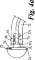
図4は、本発明による外科用リーミング器具11を示す。器具11は、回転し柔軟な回転可能駆動シャフト12を含み、この駆動シャフトは、回転可能な鋼製の出力ケーブルである。また器具11は、駆動シャフト12の第1端部12aに接続されているヘッド13を含む。ヘッド13は、基部部分13a及び切削部分13bを含む。回転可能駆動要素(図示せず)は、駆動シャフト12の第2端部12bに接続されている。 FIG. 4 shows a surgical reaming instrument 11 according to the present invention. The instrument 11 includes a rotatable and flexible
駆動シャフト12はステンレス鋼製のスリーブ14に収容され、このなかで駆動シャフト12は自由に回転する。スリーブ14は、ヘッド13付近に配置されている実質上Cの字形部分Aと、ヘッド13から離れた側のCの字形部分から延伸する真っ直ぐなハンドル部分Bとを有する。さらなる真っ直ぐな部分Cが、ヘッド13の側の実質上Cの字形部分Aから、ハンドル部分Bと一直線となるように延伸して設けられている。 The
実質上Cの字形部分Aは、大腿骨頭を完全に前方にずらす必要がなく、又は大腿骨骨幹軸を侵すことなく、リーミング装置11を寛骨臼に容易にアクセスさせることを可能とする。真っ直ぐな部分Bは、器具を操作するためのハンドルをもたらし、真っ直ぐな部分Cは、ヘッド13が回転されるとき、駆動シャフトの偏心する回転を防止する。真っ直ぐな部分B及びCは一直線であり、それによってヘッドの正確な案内が可能となる。 The substantially C-shaped portion A allows the reaming device 11 to easily access the acetabulum without having to move the femoral head completely forward or without affecting the femoral shaft. Straight portion B provides a handle for manipulating the instrument, and straight portion C prevents eccentric rotation of the drive shaft when head 13 is rotated. The straight portions B and C are straight, thereby allowing accurate head guidance.
駆動シャフト12の第1端部12aは、リーミングヘッド13の基部13aの中心から延伸しているネック部15に受容されている。駆動シャフト12の第1端部12aは、端部12aにおける駆動シャフトの偏心する回転を防止するようにネック部15に十分に固定されていなければならない。駆動シャフト12は、ネック部15を介してヘッド13を正確に回転させなければならない。 The
ネック部15には、自由に回転するカラー16が設けられ、このカラー16は、ネック部15(図4A参照)に固定して取り付けられている二つのさらなるカラー17a及び17bによりネック部15を取り囲む位置に保持されている。軸受表面は、ネック部15とカラー16の間に設けられている。ヘッド13は、スリーブ14を介して設けられている対応する開口19に受容されているとともにカラー16上にバネ付勢されている突起部18によってスリーブ14に固定されている。突起部及び開口は、スリーブ14内の固定された位置にカラー16を固定し、そのなかでネック部15は自由に回転する。突起部18は、ばねの作用に対して突起部に開口を介して圧力を適用することによって、開口19から開放することができる。 The
駆動シャフトの第2端部12bは、コネクタ20の第1端部20aに接続されている。駆動シャフト12は、偏心する回転が防止されるようにコネクタ20に固定されている。コネクタ20には、第2端部20bに雄ねじ部分21が設けられている。コネクタ20は、雄ねじ部分21によって雌ねじコネクタ22に固定され、低回転速度で高いトルクをもたらすのに適した空気によって作動される駆動要素(図示せず)に接続されている。コネクタ22は、スリーブ14内に部分的に合致するように寸法決めされ、スリーブ14内で回転可能なように軸受表面を有する。駆動シャフト12に対して適所にコネクタ22をさらに固定するのにグラブねじ23を利用することができる。 The
切削部分13bは、患者及び要求される結果に基づいて、リーミングヘッドに対して適する何らかの切削部分とすることができ、例えば適する切削部分はリーミングヘッドに対してチーズおろし器形式の切削部分である。切削部分13bは、固定された突出部24及びばね付勢されている突出部25によってヘッド13の基部13aに固定され、二つの突出部24及び25は、基部13aの周縁部の周上で互いに直径方向で対向して位置し、切削部分の周縁部の対応する開口に係合する。ばね付勢されている突出部25は、レバー26によって基部13a内に引っ込めることができる。これは基部に固定されるべきリーミングヘッドの切削部分に対する通常の固定機構である。 The cutting portion 13b can be any cutting portion suitable for the reaming head based on the patient and the desired result, for example, a suitable cutting portion is a cheese grater type cutting portion for the reaming head. The cutting portion 13b is fixed to the
リーミング器具11は、駆動シャフト12をコネクタ20と共にスリーブ14内に送り込み先ず貫通接続することによって組み立てられる。開口をスリーブ14の屈曲部に設け、それによって突き棒の利用によりコネクタ20がスリーブ14の屈曲部を廻って進むのが補助されることを可能とする。ヘッド13のネック部15は、ばね付勢されている突起部18によってスリーブ14の第1端部内に固定される。コネクタ22が、対応するねじ及びグラブねじ23によってコネクタ20に固定される。さらにコネクタ22は回転可能駆動要素に固定され、適切なリーミングヘッドが基部13aに固定される。 The reaming device 11 is assembled by feeding the
動力源を使用して、コネクタ20及び22と駆動シャフト12の回転が保護スリーブ14内で生じる。この動作の結果、ネック部15及び取り付けられているリーミングヘッドの、真っ直ぐな部分C及びBを介して長手方向に延伸する軸の周囲での回転が生じる。ネック部15、コネクタ20、スリーブ21の真っ直ぐな部分C及びBは、正確な回転が動力源からヘッド13へ駆動シャフト12の長さに沿って伝達されることを確実とする。 Using the power source, rotation of the
本発明の装置を使用して股関節の手術を実施する方法
1)手術前の段取り
患者の股関節の簡単な前後方向のレントゲン写真(図5に示す)から、直線は、大腿骨頸19の中心を下がり、通常大転子22直ぐ下方の点23において大腿骨21の側部皮質20を二等分して引かれる。この二等分する点23から大転子までの距離(Xcm)が測定される(通常5-8cm、平均6又は7cm)。Method of performing hip surgery using the device of the present invention 1) Preparation before surgery From a simple anteroposterior radiograph of the patient's hip joint (shown in FIG. 5), the straight line is centered on the
2)処置方法
麻酔
0.25%ブピバカイン30 mlを使用する大腿神経ブロックによる全身麻酔又は脊椎麻酔。
体位
正確な側臥位。
切開
図6は、股関節周囲の一連の主要な筋肉を示し、それらは大臀筋25、腸脛靱帯26、大腿筋膜張筋27、中臀筋28である。無菌マーカーペンを使用して、大転子22の位置に印を付け、ルーラーポイント「X」を利用して、大転子の先端までXcm(通常6又は7cm)離れ、大腿骨頸の中心線の大腿骨上二等分点23に位置する皮膚に印を付ける。皮膚の切り口24は、「X」の点の大腿骨の後縁から開始され、大腿骨骨幹軸21に対して45度の角度で、近位かつ後方へ8-10 cm進む。切り口24は、大臀筋25の繊維と整列している。皮下組織は、この線に沿って切開され、大臀筋25の繊維は切り口24の全長に沿って裂かれる。大臀筋25の繊維は、腸脛靱帯26の付着点前方で裂かれ、腸脛靱帯26は全く切開されない。2) Treatment method Anesthesia
General or spinal anesthesia with femoral nerve block using 30 ml of 0.25% bupivacaine.
Body position Accurate lateral position.
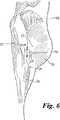
Incision FIG. 6 shows a series of major muscles around the hip joint, which are the
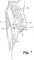
図7は、股関節周囲の一連の主要な筋肉を示し、それらは大臀筋25、腸脛靱帯26、大腿筋膜張筋27、中臀筋28である。図6に関して開示した方法の説明では、無菌マーカーペンを使用して、大転子22の位置に印を付け、ルーラーポイント「X」を利用して、大転子の先端までXcm(通常6又は7cm)離れ、大腿骨頸の中心線の大腿骨上二等分点23に位置する皮膚に印を付ける。皮膚の線24'は、点「X」から、大腿骨骨幹軸21に対して45度の角度で、近位かつ後方へ進んで印を付けられる。皮膚の切開は線24'に沿って行われる。皮膚の切り口は、線24'に沿って大腿骨21の後縁に対して4cm後方から開始され、5cmの最初の切り口を与えるこの線に沿って延伸する。線24'に沿った切り口は、大臀筋25の繊維と整列している。患者の寸法に基づき必要であれば、切り口をどちらかに延伸させることができる。皮下組織は、この線24'に沿って切開され、大臀筋25の繊維は切り口24'の全長に沿って裂かれる。大臀筋25の繊維は、腸脛靱帯26の付着点前方で裂かれ、腸脛靱帯26は全く切開されない。 FIG. 7 shows a series of major muscles around the hip joint, which are the
切り口が上臀血管及び下臀血管の分岐点にあるために、このようなやり方では最小の出血しか発生しない。大臀筋は、その繊維に対して直角に引っ込め、臀部の短外旋筋の上に重なる脂肪組織を露出させる。脂肪組織が臀部の短外旋筋を露出するように取り除かれる。完全な止血が、短外旋筋の付着点を取り囲む血管に実施される。梨状筋、下双子筋、上双子筋がそれらの付着点で分けられ、切断端部にステー縫合が適用される。短外旋筋後方の引き込みは、坐骨神経に対する損傷を防止する。大腿方形筋が、大腿骨付着点から開放される。これにより股関節の後部皮膜が露出する。股関節の全ての下部、後部、上部皮膜の切開が実施され、股関節が外される。股関節の強制的な内部回転によって、関節の前部皮膜の切開が実施可能となる。90度に膝を屈曲させることによって、腸脛靱帯26が弛緩する。内部回転において、裂かれた大臀筋25は「パチンと閉じる」傾向があることに注意しなければならない。 Because the incision is at the bifurcation of the superior and inferior blood vessels, this method produces minimal bleeding. The greater aneurysm is retracted at right angles to its fibers, exposing the adipose tissue that overlies the short external rotator muscle of the buttocks. Adipose tissue is removed to expose the short external rotator muscle of the buttocks. Complete hemostasis is performed on the blood vessel surrounding the attachment point of the short external rotator muscle. The piriformis, the lower twins, and the upper twins are separated at their attachment points, and stay stitches are applied to the cut ends. Retraction behind the short external rotator prevents damage to the sciatic nerve. The thigh square muscle is released from the thighbone attachment point. This exposes the posterior skin of the hip joint. Incisions are made in all lower, rear and upper skin of the hip joint and the hip joint is removed. Forced internal rotation of the hip joint allows incision of the anterior capsule of the joint. By bending the knee at 90 degrees, the
3a)股関節置換関節形成術に関して
大腿骨頸切截骨術が実施される。これにより寛骨臼に容易にアクセス可能となる。さらに完全な周辺の皮膜切開が実施される。さらに被覆の解放が行われる。ホーマン開創器が、寛骨臼に対して上部前方に挿入され、大腿骨が前方にずらされる。スタイルの爪が、寛骨臼周縁部の直ぐ後部の座骨に挿入される。他のホーマン開創器が、組織を下方に引っ込めるように横靭帯に対して下方周辺に挿入される。これにより寛骨臼への良好なアクセスが可能となる。前傾のその解剖学的位置において寛骨臼リーミングが、本発明の実質上Cの字形のリーミング器具により容易になされ、リーミング器具の駆動シャフトは大腿骨を何ら侵すことがない。寛骨臼の準備が完了し、接合要素又はセメントレス要素が通常のやり方で固定される。実質上Cの字形のプッシャーが、接合要素について寛骨臼要素を押し付けるのに利用され、代替的に実質上Cの字形のインパクターが、セメントレス寛骨臼要素を嵌め込むのに利用される。寛骨臼要素が固定されると、周辺の寛骨臼骨棘が除去される。大腿骨は次に準備される。大腿骨骨幹軸に容易にアクセスするために、股関節が45度に曲げられ、90度内部回転され、30-40度内転され、それによって大腿骨頸の切截骨術を施された基部がもたらされる。大腿骨は準備され、試行の大腿骨要素が挿入される。股関節は縮小され、安定性を確認される。最終的な大腿骨要素が接合され/挿入される。3a) Regarding hip replacement arthroplasty A femoral neck resection osteotomy is performed. This allows easy access to the acetabulum. In addition, a complete peripheral skin incision is performed. Furthermore, the coating is released. A Homann retractor is inserted anteriorly forward with respect to the acetabulum and the femur is displaced forward. A style nail is inserted into the sciatic bone just behind the acetabular periphery. Another Homann retractor is inserted in the lower periphery to the transverse ligament to retract the tissue downward. This allows good access to the acetabulum. Acetabular reaming is facilitated by the substantially C-shaped reaming device of the present invention in its anteversion anatomical position, and the drive shaft of the reaming device does not affect the femur at all. The preparation of the acetabulum is complete and the joining element or cementless element is secured in the usual manner. A substantially C-shaped pusher is used to press the acetabular element against the joining element, and alternatively a substantially C-shaped impactor is used to fit the cementless acetabular element. . Once the acetabular element is secured, the surrounding acetabular spines are removed. The femur is then prepared. For easy access to the femoral shaft, the hip joint is bent 45 degrees, rotated 90 degrees internally, and 30-40 degrees added, so that the base of the femoral neck undergoing incision osteotomy Brought about. The femur is prepared and a trial femoral element is inserted. The hip joint is reduced and stability is confirmed. The final femoral element is joined / inserted.
閉鎖
短外旋筋及び大腿方形筋が、大腿骨の後方に縫合される。ドレーンが傷口に挿入され、近位に導かれる。大臀筋膜がドレーン上で閉じられる。必要であれば、第2ドレーンが脂肪層に挿入され、傷口が層内で閉じられる。Closure The short external rotator and thigh quadriformus are sutured behind the femur. A drain is inserted into the wound and guided proximally. The greater gluteus fascia is closed on the drain. If necessary, a second drain is inserted into the fat layer and the wound is closed in the layer.
3a)股関節表面再建術に関して
大臀筋が「パチンと閉じる」傾向があるという事実を考慮して、前方の股関節皮膜切開は、大臀筋を裂く局面で、近位及び遠位の引き込みが交互に実施される。股関節は、内部回転、内転、屈曲の極限におくことができ、それによって傷口内に大腿骨頭を「もたらすこと」が可能となる。通常大腿骨頭は、90度の内部回転、45度の屈曲、可能な限り大きな内転において傷口内にもたらされる。大腿骨への大臀筋の付着点の部分的な解放はより多くの患者に必要とされている。大腿骨頭及び大腿骨頸は、大腿骨頭要素の寸法決めに対して測定される。大腿骨頭のガイドワイヤが、中央に集められた大腿骨頭の治具とともに挿入される。大腿骨頭の切削が、大腿骨要素を埋め込む準備段階までに、通常のやり方で完了する。如何なる大腿骨頭の骨移植又は裂け目接合もこの段階ではなされない。この段階で大腿骨頭の全寸法が縮小されている場合には、大腿骨頭を、中立位置の股関節とともに中臀筋の深部に容易にずらすことができる。またこれにより、さらに全ての前部皮膜の解放が実施され得る。さらに中立位置に大腿骨がある場合、大臀筋が弛緩される。上部前方のホーマン開創器、座骨内のスタイルの爪、下方のホーマン開創器が、寛骨臼を十分に露出する。大腿骨に対する大臀筋の付着点が、大部分の患者で解放されず、大腿骨の前方へのずれが完全に可能ではない。この理由のため、通常の寛骨臼リーミング装置は、それらが寛骨臼の解剖学的な前傾位置においてリーミングすることができないため、利用することができない。したがって実質上Cの字形のリーミング器具が寛骨臼のリーミングに利用される。リーミング器具の実質上Cの字形部分は寛骨臼の正確な解剖学的な位置におけるリーミングを可能とする。また寛骨臼の試行シャフトは実質上Cの字形輪郭を有し、また寛骨臼要素の最終的な挿入器は実質上Cの字形輪郭を有し、それによって寛骨臼要素の嵌め込みを可能とする。試行寛骨臼要素を適用させた後、最終的な寛骨臼要素が適所に嵌め込まれる。全ての周辺の寛骨臼骨棘はこの段階で除去可能である。スタイルの爪が取り除かれ、全てのホーマン開創器が取り除かれる。股関節が、90度の内部回転、45度の屈曲、内転により大腿骨頭をもたらすことが可能となる。3mmの抜け穴穿孔が、小転子に形成され、大腿骨に抜け穴が設けられる。ドレナージカニューレが、小転子の抜け穴内に挿入され、吸入装置に接続される。大腿骨頸は、裂かれた消毒綿又は特別な掛け布で取り囲まれ、大腿骨頭の骨移植又は接合のための大腿骨頭の穿孔穴開けを含む大腿骨頸の最終的な準備が実施される。大腿骨頭は乾燥され、最終的な大腿骨要素が接合される。全ての余分なセメントは取り除かれ、股関節は縮小される。傷口の決まりきった閉鎖が、上述のように実施される。3a) With regard to hip surface reconstruction, taking into account the fact that the greater gluteus muscles tend to “close”, anterior hip capsule incision is a phase in which the greater gluteus muscle is split, with proximal and distal retraction To be implemented. The hip joint can be placed in the limits of internal rotation, adduction, and flexion, thereby allowing the “femoral” head to be brought into the wound. Usually the femoral head is brought into the wound with a 90-degree internal rotation, a 45-degree flexion and the largest possible adduction. Partial release of the attachment points of the greater gluteal muscles to the femur is required by more patients. The femoral head and femoral neck are measured against the dimensioning of the femoral head element. The femoral head guidewire is inserted with the femoral head jig collected in the center. Cutting of the femoral head is completed in the usual manner by the preparation stage for embedding the femoral element. No femoral head bone graft or tear joint is made at this stage. If the total femoral head dimensions are reduced at this stage, the femoral head can be easily shifted to the deep part of the middle gluteal muscle along with the hip joint at the neutral position. This also allows a further release of the front coating. Furthermore, when the femur is in the neutral position, the greater gluteus muscle is relaxed. The upper anterior Homann retractor, styled nails in the ischia, and the lower Homann retractor fully expose the acetabulum. The attachment point of the greater gluteal muscle to the femur is not released in most patients, and a forward displacement of the femur is not entirely possible. For this reason, normal acetabular reaming devices are not available because they cannot ream at the anatomical anteversion position of the acetabulum. Accordingly, a substantially C-shaped reaming device is utilized for acetabular reaming. The substantially C-shaped portion of the reaming device allows reaming at the exact anatomical location of the acetabulum. Also, the acetabular trial shaft has a substantially C-shaped profile, and the final insert of the acetabular element has a substantially C-shaped profile, which allows the acetabular element to be fitted. And After applying the trial acetabular element, the final acetabular element is fitted in place. All surrounding acetabular spines can be removed at this stage. The style nails are removed and all Homann retractors are removed. The hip joint can provide a femoral head with 90-degree internal rotation, 45-degree flexion, and adduction. A 3 mm loophole is formed in the trochanter and a loophole is provided in the femur. A drainage cannula is inserted into the passage of the lesser trochanter and connected to the inhaler. The femoral neck is surrounded by torn sanitary cotton or a special drape and the final preparation of the femoral neck is performed, including perforation of the femoral head for bone grafting or joining of the femoral head. The femoral head is dried and the final femoral elements are joined. All excess cement is removed and the hip joint is reduced. A routine closure of the wound is performed as described above.
4)術後養生法
術後直ぐの時期において、X線による検査が行われる。十分な無痛覚が持続され、6-8時間後、患者は歩行器枠によって立ち上がることができる。翌日、ドレーンが取り除かれ、患者は歩行器枠で移動することができる。患者は、ヘモグロビンの検査が満足のいく水準であるならば、階下/リハビリテーション施設に移動することができる。患者が階下の施設から家庭環境への解放が可能であるときは、社会状況及び患者の機敏さに依存する。4) Postoperative curing method An X-ray examination is performed immediately after the operation. Sufficient analgesia persists and after 6-8 hours the patient can stand up with the walker frame. The next day, the drain is removed and the patient can move in the walker frame. The patient can be moved to a downstairs / rehabilitation facility if the hemoglobin test is satisfactory. When a patient can be released from a downstairs facility to a home environment, it depends on the social situation and the patient's agility.
Claims (35)
Translated fromJapanese前記第1端部が寛骨臼リーミングヘッドを保持するのに適合され、前記第1端部及び第2端部が、それら二つの端部の先端を介して延伸する軸を画定し、
前記シャフトの少なくとも一部が前記軸から恒久的に逸れ、それによって前記シャフトによって周囲の身体部分が侵されることを防止しながら、前記装置によって保持されているヘッドを、その正確な解剖学的な位置にある寛骨臼にアクセスさせることが可能となる外科用装置。A surgical device for holding and rotating an acetabular reaming head comprising a shaft having a length extending from a first end to a second end;
The first end is adapted to hold an acetabular reaming head, the first end and the second end defining an axis extending through the tips of the two ends;
The head held by the device is moved to its exact anatomical position while preventing at least aportion of the shaft frompermanently deviating from the axis, thereby damaging surrounding body parts. Surgical device that allows access to the acetabulum in position.
前記外科用装置の第1端部に取り付けられている寛骨臼リーミングヘッドと
を含む寛骨臼リーミングヘッド用の外科用器具。A surgical device for holding and rotating an acetabular reaming head, comprising a shaft having a length extending from a first end to a second end, wherein the first end is an acetabulum Adapted to hold a mortar reaming head, wherein the first end and the second end define an axis extending through the tips of the two ends, at least aportion of the shaft extending from the axis Allowing the head held by the device to access the acetabulum in its precise anatomical position, while preventing it frompermanently deviating and thereby affecting surrounding body parts by the shaft A surgical device that enables
A surgical instrument for an acetabular reaming head, comprising: an acetabular reaming head attached to a first end of the surgical device.
前記シャフトの少なくとも一部が前記軸から恒久的に逸れ、それによって前記シャフトによって周囲の身体部分が侵されることを防止しながら、前記ヘッドを、その正確な解剖学的な位置にある寛骨臼にアクセスさせることができる外科用器具。A surgical instrument suitable for reaming an acetabulum comprising a shaft having a first end and a second end, the shaft being connected to a head at the first end, wherein the first In which the end and the second end define an axis extending through the tips of the two ends;
The acetabulum in its exact anatomical position while preventing at least aportion of the shaft frompermanently deviating from the axis and thereby invading surrounding body parts by the shaft Surgical instruments that can be accessed.
a)寛骨臼リーミングヘッドを保持し回転させるための外科用装置であって、第1端部から第2端部に延伸するある長さを有するシャフトを含むものにおいて、前記第1端部が寛骨臼リーミングヘッドを保持するのに適合され、前記第1端部及び第2端部が、それら二つの端部の先端を介して延伸する軸を画定し、前記シャフトの少なくとも一部が前記軸から恒久的に逸れ、それによって前記シャフトによって周囲の身体部分が侵されることを防止しながら、前記装置によって保持されているヘッドを、その正確な解剖学的な位置にある寛骨臼にアクセスさせることを可能とする外科用装置と、
b)選択された寸法の1つ又はそれ以上の寛骨臼リーミングヘッドであって、それぞれが前記外科用装置の第1端部とともに操作され、患者の寛骨臼凹部を整形する1つ又はそれ以上の寛骨臼リーミングヘッドと
を含む用具一式。A set of tools for performing hip surgery on a patient,
a) a surgical device for holding and rotating an acetabular reaming head, comprising a shaft having a length extending from a first end to a second end, wherein the first end is Adapted to hold an acetabular reaming head, wherein the first end and the second end define an axis extending through the tips of the two ends, at least aportion of the shaft being Access the head held by the device to the acetabulum in its exact anatomical position while preventing the shaft frompermanently deviating and thereby affecting the surrounding body parts. A surgical device that makes it possible to
b) one or more acetabular reaming heads of selected dimensions, each operated with the first end of the surgical device, to shape the patient's acetabular recess; A set of tools including the above acetabular reaming head.
前記ヘッドを配置するように適合されている第1端部から第2端部に延伸するある長さを有するシャフトであって、前記第1端部及び第2端部がそれら二つの端部の先端を介して延伸する軸を画定するものにおいて、前記シャフトの少なくとも一部が前記軸から恒久的に逸れ、それによって前記シャフトによって周囲の身体部分が侵されることを防止しながら、前記ヘッドを、その正確な解剖学的な位置にある患者の骨空洞にアクセスさせることを可能とするシャフトと、
外科医によって操作されるハンドルを有し、前記シャフトを取り囲む保護スリーブと、
前記シャフトに結合されている動力駆動要素と、
洗浄のために、前記第1端部から前記ヘッドを容易に取り外すための手段と
を含む外科用装置。A surgical device for holding and rotating an acetabular reaming head comprising:
A shaft having a length extending from a first end to a second end adapted to position the head, wherein the first end and the second end are of the two ends; In defining an axis extending through a tip, while preventing at least aportion of the shaft frompermanently deviating from the axis, thereby damaging surrounding body parts by the shaft, A shaft that allows access to the patient's bone cavity in its exact anatomical location;
A protective sleeve having a handle operated by a surgeon and surrounding the shaft;
A power drive element coupled to the shaft;
For cleaning, apparatus forincluding an outer family and means for easy removal of the head from the first end.
前記外科用装置の第1端部に取り付けられた寛骨臼リーミングヘッドと
を含む外科用器具であって、前記外科用装置が、
前記ヘッドを配置するように適合されている第1端部から第2端部に延伸するある長さを有するシャフトであって、前記第1端部及び第2端部がそれら二つの端部の先端を介して延伸する軸を画定するものにおいて、前記シャフトの少なくとも一部が前記軸から恒久的に逸れ、それによって前記シャフトによって周囲の身体部分が侵されることを防止しながら、前記ヘッドを、その正確な解剖学的な位置にある患者の骨空洞にアクセスさせることを可能とするシャフトと、
外科医によって操作されるハンドルを有し、前記シャフトを取り囲む保護スリーブと、
前記シャフトに結合されている動力駆動要素と、
洗浄のために、前記第1端部から前記ヘッドを容易に取り外すための手段と
を含む、外科用器具。A surgical device for holding and rotating theacetabular reaming head,
An acetabular reaming head attached to a first end of the surgical device;
A surgical instrument comprising: the surgical device comprising:
A shaft having a length extending in the second end portion from a first end that is adapted to so thatto place the head, the first and second ends thereof two ends of the shallbe defining an axis which extends through the tip,permanently deviate at leasta portion of said shaft from said axis, whereby while preventing that the body part of the periphery attacked by said shaft, said head A shaft that allows access to the patient's bone cavity in its exact anatomical location;
A protective sleeve having a handle operated by a surgeon and surrounding the shaft;
A power drive element coupled to the shaft;
For washing, and means for removing the head easily from the firstend, the surgical instrument.
前記ヘッドを配置するように適合されている第1端部から第2端部に延伸するある長さを有するシャフトであって、前記第1端部及び第2端部がそれら二つの端部の先端を介して延伸する軸を画定するものにおいて、前記シャフトの少なくとも一部が前記軸から恒久的に逸れ、前記軸から逸れている前記シャフトの部分が実質上Cの字形に形成され、それによって前記シャフトによって周囲の身体部分が侵されることを防止しながら、前記ヘッドを、その正確な解剖学的な位置にある寛骨臼にアクセスさせることを可能とするシャフトと、
外科医によって操作されるハンドルを有し、前記シャフトを取り囲む保護スリーブと、
前記シャフトに結合されている動力駆動要素と、
洗浄のために、前記第1端部から前記ヘッドを容易に取り外すための手段と
を含む外科用装置。A surgical device for holding and rotating an acetabular reaming head comprising:
A shaft having a length extending in the second end portion from a first end that is adapted to so thatto place the head, the first and second ends thereof two ends in shallbe defining an axis which extends through the tip, at leasta portion of said shaft ispermanently deviate from the axis,parts ofthe said shaft deviates from said axis is formed in the shape of a substantially C A shaft that allows the head to access the acetabulum in its exact anatomical position, thereby preventing the shaft from damaging surrounding body parts;
A protective sleeve having a handle operated by a surgeon and surrounding the shaft;
A power drive element coupled to the shaft;
Means for easily removing the head from the first end for cleaning.
前記外科用装置の第1端部に取り付けられた寛骨臼リーミングヘッドと
を含む外科用器具であって、前記外科用装置が、
前記ヘッドを配置するように適合されている第1端部から第2端部に延伸するある長さを有するシャフトであって、前記第1端部及び第2端部がそれら二つの端部の先端を介して延伸する軸を画定するものにおいて、前記シャフトの少なくとも一部が前記軸から恒久的に逸れ、前記軸から逸れている前記シャフトの部分が実質上Cの字形に形成され、それによって前記シャフトによって周囲の身体部分が侵されることを防止しながら、前記ヘッドを、その正確な解剖学的な位置にある寛骨臼にアクセスさせることを可能とするシャフトと、
外科医によって操作されるハンドルを有し、前記シャフトを取り囲む保護スリーブと、
前記シャフトに結合されている動力駆動要素と、
洗浄のために、前記第1端部から前記ヘッドを容易に取り外すための手段と
を含む、外科用器具。A surgical device for holding and rotating the acetabular reaming head;
An acetabular reaming head attached to a first end of the surgical device;
A surgical instrument comprising: the surgical device comprising:
A shaft having a length extending in the second end portion from a first end that is adapted to so thatto place the head, the first and second ends thereof two ends in shallbe defining an axis which extends through the tip, at leasta portion of said shaft ispermanently deviate from the axis,parts ofthe said shaft deviates from said axis is formed in the shape of a substantially C A shaft that allows the head to access the acetabulum in its exact anatomical position, thereby preventing the shaft from damaging surrounding body parts;
A protective sleeve having a handle operated by a surgeon and surrounding the shaft;
A power drive element coupled to the shaft;
For washing, and means for removing the head easily from the firstend, the surgical instrument.
Applications Claiming Priority (4)
| Application Number | Priority Date | Filing Date | Title |
|---|---|---|---|
| GB0202934AGB0202934D0 (en) | 2002-02-08 | 2002-02-08 | Improved surgical devices and methods of use |
| GB0205043AGB0205043D0 (en) | 2002-03-05 | 2002-03-05 | Improved surgical devices and methods of use |
| GB0219696AGB0219696D0 (en) | 2002-08-23 | 2002-08-23 | Improved surgical devices and methods of use |
| PCT/GB2003/000557WO2003065906A2 (en) | 2002-02-08 | 2003-02-07 | Device for holding and rotating an acetabulum reamer |
Publications (2)
| Publication Number | Publication Date |
|---|---|
| JP2005516662A JP2005516662A (en) | 2005-06-09 |
| JP4384498B2true JP4384498B2 (en) | 2009-12-16 |
Family
ID=27738829
Family Applications (1)
| Application Number | Title | Priority Date | Filing Date |
|---|---|---|---|
| JP2003565336AExpired - LifetimeJP4384498B2 (en) | 2002-02-08 | 2003-02-07 | Improved surgical device and method of use |
Country Status (7)
| Country | Link |
|---|---|
| US (3) | US7819875B2 (en) |
| EP (1) | EP1471837B1 (en) |
| JP (1) | JP4384498B2 (en) |
| KR (1) | KR100964762B1 (en) |
| CN (1) | CN100515353C (en) |
| AU (1) | AU2003208401A1 (en) |
| WO (1) | WO2003065906A2 (en) |
Families Citing this family (90)
| Publication number | Priority date | Publication date | Assignee | Title |
|---|---|---|---|---|
| US6991656B2 (en)* | 2000-04-26 | 2006-01-31 | Dana Mears | Method and apparatus for performing a minimally invasive total hip arthroplasty |
| US6676706B1 (en) | 2000-04-26 | 2004-01-13 | Zimmer Technology, Inc. | Method and apparatus for performing a minimally invasive total hip arthroplasty |
| JP4384498B2 (en) | 2002-02-08 | 2009-12-16 | チャナ,ガーシャラン,シン | Improved surgical device and method of use |
| US7559928B2 (en)* | 2002-02-12 | 2009-07-14 | Alexandria Research Technologies, Llc | Apparatus and method for minimally invasive total joint replacement |
| WO2003092513A1 (en) | 2002-04-30 | 2003-11-13 | Precimed S.A. | Reamer spindle for minimally invasive joint surgery |
| US20030229352A1 (en) | 2002-06-10 | 2003-12-11 | Penenberg Brad L. | Apparatus for and method of providing a hip replacement |
| US7651501B2 (en) | 2004-03-05 | 2010-01-26 | Wright Medical Technology, Inc. | Instrument for use in minimally invasive hip surgery |
| US6997928B1 (en) | 2002-06-10 | 2006-02-14 | Wright Medical Technology, Inc. | Apparatus for and method of providing a hip replacement |
| US7326215B2 (en)* | 2002-10-30 | 2008-02-05 | Symmetry Medical, Inc. | Curved surgical tool driver |
| US7247158B2 (en) | 2003-02-04 | 2007-07-24 | Wright Medical Technology, Inc. | Acetabular impactor |
| WO2004071310A1 (en) | 2003-02-10 | 2004-08-26 | Smith & Nephew, Inc. | Acetabular reamer |
| US20040172036A1 (en)* | 2003-02-27 | 2004-09-02 | Donald Dye | Angled acetabular reamer and method of use |
| US7749227B2 (en) | 2003-04-28 | 2010-07-06 | Greatbatch Medical S.A. | Precision assembleable surgical tool handle with limited-play interconnect mechanism |
| US7297166B2 (en) | 2003-06-25 | 2007-11-20 | Depuy Products, Inc. | Assembly tool for modular implants and associated method |
| US7074224B2 (en) | 2003-06-25 | 2006-07-11 | Depuy Products, Inc. | Modular tapered reamer for bone preparation and associated method |
| US7582092B2 (en) | 2003-06-25 | 2009-09-01 | Depuy Products, Inc. | Assembly tool for modular implants and associated method |
| US8998919B2 (en) | 2003-06-25 | 2015-04-07 | DePuy Synthes Products, LLC | Assembly tool for modular implants, kit and associated method |
| US7037310B2 (en) | 2003-10-21 | 2006-05-02 | Wright Medical Technology Inc | Acetabular impactor |
| US7105028B2 (en) | 2003-10-21 | 2006-09-12 | Wright Medical Technology, Inc. | Tissue preserving and minimally invasive hip replacement surgical procedure |
| US20050137603A1 (en)* | 2003-11-12 | 2005-06-23 | Kevin Belew | Acetabular cup positioning instrument |
| US8657824B2 (en) | 2003-11-18 | 2014-02-25 | Smith & Nephew, Inc. | Universal double offset surgical instrument |
| DE602004023422D1 (en) | 2003-11-18 | 2009-11-12 | Smith & Nephew Inc | OPERATIVE TECHNIQUE AND INSTRUMENTS FOR MINIMAL INCISION HIP ARTHOPLASTY SURGERY |
| US7785328B2 (en) | 2003-12-30 | 2010-08-31 | Depuy Products, Inc. | Minimally invasive bone miller apparatus |
| US20050149047A1 (en) | 2004-01-05 | 2005-07-07 | Paramount Medical Instruments, L.L.C. | Method of attaching an implant to an impactor |
| US7488322B2 (en)* | 2004-02-11 | 2009-02-10 | Medtronic, Inc. | High speed surgical cutting instrument |
| US8277457B1 (en) | 2004-12-09 | 2012-10-02 | Greatbatch Medical S.A. | Orthopaedic inserter using a collet mechanism |
| US7682363B2 (en)* | 2004-12-09 | 2010-03-23 | Greatbatch Medical S.A. | Inserter for minimally invasive joint surgery |
| GB0503529D0 (en)* | 2005-02-21 | 2005-03-30 | Smith & Nephew Inc | Medical device |
| WO2006100658A2 (en)* | 2005-03-22 | 2006-09-28 | Atropos Limited | A surgical instrument |
| US7976548B2 (en)* | 2005-08-24 | 2011-07-12 | Greatbatch Medical S.A. | Surgical tool holder for facilitated sterilization |
| US8398639B2 (en)* | 2005-09-29 | 2013-03-19 | Symmetry Medical Manufacturing, Inc. | Minimally invasive surgical driver |
| US7621921B2 (en)* | 2006-01-25 | 2009-11-24 | Symmetry Medical, Inc | Split thread orthopaedic implant impactor |
| DE102007020484A1 (en)* | 2006-05-01 | 2007-12-13 | Precimed S.A. | Insertion instrument for minimally invasive joint surgery with exchangeable thread |
| DE202006010069U1 (en)* | 2006-06-28 | 2007-11-08 | Waldemar Link Gmbh & Co. Kg | Insertion device for joint sockets of prostheses |
| US8597298B2 (en) | 2006-09-29 | 2013-12-03 | DePuy Synthes Products, LLC | Proximal reamer |
| US8556912B2 (en) | 2007-10-30 | 2013-10-15 | DePuy Synthes Products, LLC | Taper disengagement tool |
| US8518050B2 (en) | 2007-10-31 | 2013-08-27 | DePuy Synthes Products, LLC | Modular taper assembly device |
| US8535323B2 (en)* | 2008-01-25 | 2013-09-17 | DePuy Synthes Products, LLC | Constraining ring inserter |
| GB0803625D0 (en)* | 2008-02-28 | 2008-04-02 | Depuy Int Ltd | Acetabular alignment guide |
| US8167882B2 (en) | 2008-09-30 | 2012-05-01 | Depuy Products, Inc. | Minimally invasive bone miller apparatus |
| US8398650B1 (en) | 2009-01-27 | 2013-03-19 | Greatbatch Medical S.A. | Offset cup impactor with an expandable dome for double mobility implants |
| JP5464892B2 (en) | 2009-04-15 | 2014-04-09 | Ntn株式会社 | Remote control type actuator |
| CN102448389B (en) | 2009-05-26 | 2014-10-15 | 捷迈公司 | Handheld tool for driving a bone pin into a fractured bone |
| US8533921B2 (en) | 2010-06-15 | 2013-09-17 | DePuy Synthes Products, LLC | Spiral assembly tool |
| EP2422754B1 (en) | 2010-08-27 | 2014-11-05 | Greatbatch Medical SA | Offset cup impactor with a grasping plate for double mobility implants |
| US9095452B2 (en) | 2010-09-01 | 2015-08-04 | DePuy Synthes Products, Inc. | Disassembly tool |
| FR2967046A1 (en) | 2010-11-10 | 2012-05-11 | Tornier Sa | ORTHOPEDIC BONE PREPARATION MACHINE, ESPECIALLY GLENOIDIAN PREPARATION |
| US9119731B2 (en) | 2011-01-17 | 2015-09-01 | Greatbach Medical S.A. | Straight cup impactor |
| EP2476397B1 (en) | 2011-01-17 | 2015-10-21 | Greatbatch Medical SA | Straight cup impactor with lever arm |
| US9421132B2 (en)* | 2011-02-04 | 2016-08-23 | University Of Massachusetts | Negative pressure wound closure device |
| ES2635496T3 (en) | 2011-04-06 | 2017-10-04 | Depuy Synthes Products Llc | Modular Orthopedic Hip Prosthesis |
| US9119722B1 (en) | 2011-08-18 | 2015-09-01 | Sharat Kusuma | Measurement and placement techniques in hip resurfacing and the like |
| EP2561835B1 (en) | 2011-08-26 | 2016-03-16 | Greatbatch Medical SA | Straight cup impactor |
| US9028502B2 (en) | 2011-09-23 | 2015-05-12 | Greatbatch Medical S.A. | Ceramic implant holder |
| AU2013264937B2 (en) | 2012-05-24 | 2018-04-19 | Smith & Nephew Inc. | Devices and methods for treating and closing wounds with negative pressure |
| CA2878713C (en) | 2012-07-11 | 2020-09-22 | Zimmer, Inc. | Bone fixation tool |
| MX369689B (en) | 2012-07-16 | 2019-11-19 | Smith & Nephew Inc | Negative pressure wound closure device. |
| WO2014063197A1 (en)* | 2012-10-25 | 2014-05-01 | Inertial Orthopaedic Navigation Solutions Pty Ltd | A surgical instrument |
| US20170319348A1 (en) | 2015-08-10 | 2017-11-09 | Catalyst Orthoscience Inc. | Arthroplasty prostheses with multi-axis fixation |
| US10973646B2 (en) | 2013-03-11 | 2021-04-13 | Catalyst Orthoscience Inc. | Stabilized drill guide |
| US9814588B2 (en) | 2015-08-10 | 2017-11-14 | Catalyst Orthoscience Inc. | Glenoid arthroplasty with multi-directional fixation |
| US9814471B2 (en)* | 2013-03-11 | 2017-11-14 | Catalyst Orthoscience Inc. | Glenoid arthroplasty and offset reamers |
| USD730522S1 (en) | 2013-03-11 | 2015-05-26 | Catalyst Orthopaedics Llc | Implant |
| US11007063B2 (en) | 2013-03-11 | 2021-05-18 | Catalyst Orthoscience Inc. | Offset reamers |
| US10124098B2 (en) | 2013-03-13 | 2018-11-13 | Smith & Nephew, Inc. | Negative pressure wound closure device and systems and methods of use in treating wounds with negative pressure |
| CN106170275B (en) | 2013-10-21 | 2021-05-07 | 史密夫和内修有限公司 | Negative pressure wound closure device |
| CA2944654C (en) | 2014-04-03 | 2020-07-14 | Zimmer, Inc. | Orthopedic tool for bone fixation |
| US10568649B2 (en) | 2014-05-06 | 2020-02-25 | Howmedica Osteonics Corp. | Acetabular reamer |
| US11234826B2 (en) | 2014-06-30 | 2022-02-01 | Howmedica Osteonics Corp. | Augmented glenoid components and devices for implanting the same |
| US10028838B2 (en) | 2014-06-30 | 2018-07-24 | Tornier, Inc. | Augmented glenoid components and devices for implanting the same |
| US20160135862A1 (en)* | 2014-11-17 | 2016-05-19 | Spinal Elements, Inc. | Curved surgical tools |
| AU2016254119A1 (en) | 2015-04-29 | 2017-10-05 | Smith & Nephew Inc. | Negative pressure wound closure device |
| WO2017019332A1 (en)* | 2015-07-27 | 2017-02-02 | Hip Innovation Technology, LLC | Acetabular cup extractor |
| WO2017029546A2 (en) | 2015-08-18 | 2017-02-23 | Incipio Devices Sa | Offset reamer driver |
| KR102603509B1 (en) | 2015-08-27 | 2023-11-16 | 힙 이노베이션 테크놀러지 엘엘씨 | Surgical trays, instruments and methods for removing components of a hip replacement prosthesis |
| US11471586B2 (en) | 2015-12-15 | 2022-10-18 | University Of Massachusetts | Negative pressure wound closure devices and methods |
| US11129724B2 (en) | 2016-07-28 | 2021-09-28 | Howmedica Osteonics Corp. | Stemless prosthesis anchor component |
| WO2018033788A1 (en) | 2016-08-18 | 2018-02-22 | Incipio Devices Sa | Offset reamer driver |
| US10966704B2 (en) | 2016-11-09 | 2021-04-06 | Biomet Sports Medicine, Llc | Methods and systems for stitching soft tissue to bone |
| AU2018279732B2 (en) | 2017-06-09 | 2024-03-07 | Mako Surgical Corp. | Systems and tools for positioning workpieces with surgical robots |
| GB201802789D0 (en) | 2018-02-21 | 2018-04-04 | Depuy Ireland Ultd Co | Acetabular reamer handle and method of reaming an acetabulum |
| AU2020204539B2 (en) | 2019-07-12 | 2024-10-31 | Howmedica Osteonics Corp. | Augmented glenoid design |
| US11426285B2 (en) | 2019-09-05 | 2022-08-30 | Howmedica Osteonics Corp. | Truss glenoid augment |
| AU2021200854A1 (en) | 2020-03-03 | 2021-09-16 | Howmedica Osteonics Corp. | Glenoid implant with additively manufactured fixation posts |
| CN111227995B (en)* | 2020-03-19 | 2022-02-15 | 闫新峰 | A femoral head prosthesis component |
| CN112190303B (en)* | 2020-10-29 | 2022-03-11 | 北京市春立正达医疗器械股份有限公司 | Joint mortar nest file |
| WO2022140463A1 (en) | 2020-12-22 | 2022-06-30 | Herzlinger Regina E | Methods, systems, and apparatus for administering a monoclonal and/or polyclonal antibody treatment via rapid infusion |
| US11806507B2 (en) | 2020-12-22 | 2023-11-07 | Regina E. HERZLINGER | Methods, systems, and apparatus for administering an antibody treatment via infusion |
| US12133966B2 (en) | 2020-12-22 | 2024-11-05 | Regina E. HERZLINGER | Methods, systems, and apparatus for administering an antibody treatment via infusion |
| CN113842252A (en)* | 2021-10-21 | 2021-12-28 | 栗磊 | Artificial hip joint prosthesis for preventing dislocation of femur and iliofemoral ligament |
Family Cites Families (28)
| Publication number | Priority date | Publication date | Assignee | Title |
|---|---|---|---|---|
| FR1041311A (en) | 1951-08-24 | 1953-10-22 | Chevalier Et Fils E | Surgical burr |
| DE2914455A1 (en) | 1979-04-10 | 1980-10-23 | Maschf Augsburg Nuernberg Ag | DEVICE FOR PRODUCING A COLLECTION IN A BONE |
| US4528980A (en)* | 1983-10-19 | 1985-07-16 | Howmedica, Inc. | Acetabulum sizer and drill guide |
| US5171312A (en)* | 1990-05-03 | 1992-12-15 | Othy, Inc. | Tool driver |
| US5269785A (en)* | 1990-06-28 | 1993-12-14 | Bonutti Peter M | Apparatus and method for tissue removal |
| US5176711A (en)* | 1991-03-06 | 1993-01-05 | Grimes James B | Acetabular revision system |
| CN2094322U (en)* | 1991-06-15 | 1992-01-29 | 阎德强 | Electric hole drill for man-made full hip joint replacement |
| JPH05123334A (en)* | 1991-11-07 | 1993-05-21 | Aisin Seiki Co Ltd | Surgical apparatus for substitution with artificial joint |
| US5411514A (en) | 1992-09-30 | 1995-05-02 | Linvatec Corporation | Bendable variable angle rotating shaver |
| US5474560A (en)* | 1994-09-26 | 1995-12-12 | Zimmer, Inc. | Prosthetic acetabular cup inserter |
| US6436107B1 (en) | 1996-02-20 | 2002-08-20 | Computer Motion, Inc. | Method and apparatus for performing minimally invasive surgical procedures |
| DE69734845T2 (en) | 1996-09-24 | 2006-09-14 | Xomed Surgical Products, Inc., North Jacksonville | Assembly of surgical blades |
| US5851208A (en) | 1996-10-15 | 1998-12-22 | Linvatec Corporation | Rotatable surgical burr |
| GB2323036B (en)* | 1997-03-14 | 2001-04-11 | Finsbury | Prosthetic implant and surgical tool |
| US5976144A (en)* | 1998-03-18 | 1999-11-02 | Vozeh Equipment Corp. | Hollow dome reamer with removable teeth |
| US5951561A (en) | 1998-06-30 | 1999-09-14 | Smith & Nephew, Inc. | Minimally invasive intramedullary nail insertion instruments and method |
| ES2265929T3 (en)* | 1999-03-30 | 2007-03-01 | Novartis Ag | FTALAZINE DERIVATIVES FOR THE TREATMENT OF INFLAMMATORY DISEASES. |
| US6533749B1 (en) | 1999-09-24 | 2003-03-18 | Medtronic Xomed, Inc. | Angled rotary tissue cutting instrument with flexible inner member |
| US6312438B1 (en)* | 2000-02-01 | 2001-11-06 | Medtronic Xomed, Inc. | Rotary bur instruments having bur tips with aspiration passages |
| US6447514B1 (en)* | 2000-03-07 | 2002-09-10 | Zimmer | Polymer filled hip fracture fixation device |
| US6676706B1 (en)* | 2000-04-26 | 2004-01-13 | Zimmer Technology, Inc. | Method and apparatus for performing a minimally invasive total hip arthroplasty |
| US20030130741A1 (en)* | 2002-01-07 | 2003-07-10 | Mcminn Derek James Wallace | Hip prosthesis |
| JP4384498B2 (en) | 2002-02-08 | 2009-12-16 | チャナ,ガーシャラン,シン | Improved surgical device and method of use |
| WO2003092513A1 (en) | 2002-04-30 | 2003-11-13 | Precimed S.A. | Reamer spindle for minimally invasive joint surgery |
| US20030229352A1 (en)* | 2002-06-10 | 2003-12-11 | Penenberg Brad L. | Apparatus for and method of providing a hip replacement |
| US7004946B2 (en)* | 2002-10-30 | 2006-02-28 | Symmetry Medical, Inc. | Acetabular cup impactor |
| US7326215B2 (en)* | 2002-10-30 | 2008-02-05 | Symmetry Medical, Inc. | Curved surgical tool driver |
| US7008430B2 (en) | 2003-01-31 | 2006-03-07 | Howmedica Osteonics Corp. | Adjustable reamer with tip tracker linkage |
- 2003
- 2003-02-07JPJP2003565336Apatent/JP4384498B2/ennot_activeExpired - Lifetime
- 2003-02-07EPEP03706689.1Apatent/EP1471837B1/ennot_activeExpired - Lifetime
- 2003-02-07KRKR1020047012249Apatent/KR100964762B1/ennot_activeExpired - Lifetime
- 2003-02-07CNCNB038061899Apatent/CN100515353C/ennot_activeExpired - Lifetime
- 2003-02-07USUS10/503,788patent/US7819875B2/enactiveActive
- 2003-02-07WOPCT/GB2003/000557patent/WO2003065906A2/enactiveApplication Filing
- 2003-02-07AUAU2003208401Apatent/AU2003208401A1/ennot_activeAbandoned
- 2005
- 2005-05-05USUS11/122,092patent/US20050222572A1/ennot_activeAbandoned
- 2010
- 2010-01-28USUS12/695,570patent/US8282639B2/ennot_activeExpired - Fee Related
Also Published As
| Publication number | Publication date |
|---|---|
| KR20040103927A (en) | 2004-12-09 |
| EP1471837B1 (en) | 2018-11-07 |
| KR100964762B1 (en) | 2010-06-21 |
| WO2003065906A3 (en) | 2003-11-27 |
| JP2005516662A (en) | 2005-06-09 |
| US20100130979A1 (en) | 2010-05-27 |
| US7819875B2 (en) | 2010-10-26 |
| AU2003208401A1 (en) | 2003-09-02 |
| US20050222572A1 (en) | 2005-10-06 |
| WO2003065906A2 (en) | 2003-08-14 |
| EP1471837A2 (en) | 2004-11-03 |
| CN1642487A (en) | 2005-07-20 |
| CN100515353C (en) | 2009-07-22 |
| US8282639B2 (en) | 2012-10-09 |
| AU2003208401A8 (en) | 2003-09-02 |
| US20050131414A1 (en) | 2005-06-16 |
Similar Documents
| Publication | Publication Date | Title |
|---|---|---|
| JP4384498B2 (en) | Improved surgical device and method of use | |
| US12419655B2 (en) | Flexible ACL instrumentation, kit and method | |
| JP4832522B2 (en) | Apparatus and method for minimally invasive total joint replacement | |
| EP2510886B1 (en) | Flexible ACL instrumentation | |
| US20030229357A1 (en) | Femoral head holder and impaction instrument and method of use | |
| JP2012081293A (en) | Operation apparatus | |
| JP2014054543A (en) | Improved method and apparatus for hip replacement | |
| CN111818880B (en) | Arthroscopic shoulder arthroplasty, components, instruments, and methods of use thereof | |
| CN120076762A (en) | Surgical tool for creating bone tunnels | |
| US20250032132A1 (en) | Medical Device and method for treatment of a hip joint | |
| US11382640B2 (en) | Medical device and method for treatment of hip joint | |
| JP5681181B2 (en) | Hip apparatus, system and method |
Legal Events
| Date | Code | Title | Description |
|---|---|---|---|
| A621 | Written request for application examination | Free format text:JAPANESE INTERMEDIATE CODE: A621 Effective date:20060111 | |
| A131 | Notification of reasons for refusal | Free format text:JAPANESE INTERMEDIATE CODE: A131 Effective date:20090210 | |
| A601 | Written request for extension of time | Free format text:JAPANESE INTERMEDIATE CODE: A601 Effective date:20090430 | |
| A602 | Written permission of extension of time | Free format text:JAPANESE INTERMEDIATE CODE: A602 Effective date:20090512 | |
| A521 | Request for written amendment filed | Free format text:JAPANESE INTERMEDIATE CODE: A523 Effective date:20090807 | |
| TRDD | Decision of grant or rejection written | ||
| A01 | Written decision to grant a patent or to grant a registration (utility model) | Free format text:JAPANESE INTERMEDIATE CODE: A01 Effective date:20090908 | |
| A01 | Written decision to grant a patent or to grant a registration (utility model) | Free format text:JAPANESE INTERMEDIATE CODE: A01 | |
| A61 | First payment of annual fees (during grant procedure) | Free format text:JAPANESE INTERMEDIATE CODE: A61 Effective date:20090925 | |
| FPAY | Renewal fee payment (event date is renewal date of database) | Free format text:PAYMENT UNTIL: 20121002 Year of fee payment:3 | |
| R150 | Certificate of patent or registration of utility model | Ref document number:4384498 Country of ref document:JP Free format text:JAPANESE INTERMEDIATE CODE: R150 Free format text:JAPANESE INTERMEDIATE CODE: R150 | |
| FPAY | Renewal fee payment (event date is renewal date of database) | Free format text:PAYMENT UNTIL: 20131002 Year of fee payment:4 | |
| R250 | Receipt of annual fees | Free format text:JAPANESE INTERMEDIATE CODE: R250 | |
| R250 | Receipt of annual fees | Free format text:JAPANESE INTERMEDIATE CODE: R250 | |
| R250 | Receipt of annual fees | Free format text:JAPANESE INTERMEDIATE CODE: R250 | |
| R250 | Receipt of annual fees | Free format text:JAPANESE INTERMEDIATE CODE: R250 | |
| R250 | Receipt of annual fees | Free format text:JAPANESE INTERMEDIATE CODE: R250 | |
| R250 | Receipt of annual fees | Free format text:JAPANESE INTERMEDIATE CODE: R250 | |
| R250 | Receipt of annual fees | Free format text:JAPANESE INTERMEDIATE CODE: R250 | |
| R250 | Receipt of annual fees | Free format text:JAPANESE INTERMEDIATE CODE: R250 | |
| R250 | Receipt of annual fees | Free format text:JAPANESE INTERMEDIATE CODE: R250 | |
| R250 | Receipt of annual fees | Free format text:JAPANESE INTERMEDIATE CODE: R250 | |
| R250 | Receipt of annual fees | Free format text:JAPANESE INTERMEDIATE CODE: R250 | |
| EXPY | Cancellation because of completion of term |