JP4384033B2 - Method and apparatus for anastomosis - Google Patents
Method and apparatus for anastomosisDownload PDFInfo
- Publication number
- JP4384033B2 JP4384033B2JP2004516032AJP2004516032AJP4384033B2JP 4384033 B2JP4384033 B2JP 4384033B2JP 2004516032 AJP2004516032 AJP 2004516032AJP 2004516032 AJP2004516032 AJP 2004516032AJP 4384033 B2JP4384033 B2JP 4384033B2
- Authority
- JP
- Japan
- Prior art keywords
- fastener
- leg portion
- locking
- fastener portion
- anchoring
- Prior art date
- Legal status (The legal status is an assumption and is not a legal conclusion. Google has not performed a legal analysis and makes no representation as to the accuracy of the status listed.)
- Expired - Fee Related
Links
- 238000000034methodMethods0.000titledescription19
- 230000003872anastomosisEffects0.000titledescription17
- 238000004873anchoringMethods0.000claimsdescription61
- 238000003780insertionMethods0.000claimsdescription23
- 230000037431insertionEffects0.000claimsdescription23
- 229920000954PolyglycolidePolymers0.000claimsdescription4
- 239000000463materialSubstances0.000claimsdescription4
- 239000004633polyglycolic acidSubstances0.000claimsdescription4
- RTAQQCXQSZGOHL-UHFFFAOYSA-NTitaniumChemical compound[Ti]RTAQQCXQSZGOHL-UHFFFAOYSA-N0.000claimsdescription3
- 239000004626polylactic acidSubstances0.000claimsdescription3
- 229910001220stainless steelInorganic materials0.000claimsdescription3
- 239000010935stainless steelSubstances0.000claimsdescription3
- 239000010936titaniumSubstances0.000claimsdescription3
- 229910052719titaniumInorganic materials0.000claimsdescription3
- 229920000747poly(lactic acid)Polymers0.000claimsdescription2
- 210000003932urinary bladderAnatomy0.000description34
- 210000002307prostateAnatomy0.000description15
- 238000013459approachMethods0.000description13
- 210000003708urethraAnatomy0.000description10
- 238000001356surgical procedureMethods0.000description7
- 210000000056organAnatomy0.000description6
- 238000011472radical prostatectomyMethods0.000description5
- 210000001519tissueAnatomy0.000description5
- 238000011471prostatectomyMethods0.000description3
- 210000003689pubic boneAnatomy0.000description3
- 210000001625seminal vesicleAnatomy0.000description3
- 201000010653vesiculitisDiseases0.000description3
- 206010060862Prostate cancerDiseases0.000description2
- 208000000236Prostatic NeoplasmsDiseases0.000description2
- 230000008901benefitEffects0.000description2
- 238000002224dissectionMethods0.000description2
- 210000000981epitheliumAnatomy0.000description2
- 238000012986modificationMethods0.000description2
- 230000004048modificationEffects0.000description2
- 210000000664rectumAnatomy0.000description2
- 0CCC(CCC(*)CCCN)*CChemical compoundCCC(CCC(*)CCCN)*C0.000description1
- 210000001015abdomenAnatomy0.000description1
- 210000000683abdominal cavityAnatomy0.000description1
- 210000003484anatomyAnatomy0.000description1
- 210000000436anusAnatomy0.000description1
- 238000004132cross linkingMethods0.000description1
- 238000011161developmentMethods0.000description1
- 238000005516engineering processMethods0.000description1
- 230000035876healingEffects0.000description1
- 210000001165lymph nodeAnatomy0.000description1
- 210000004877mucosaAnatomy0.000description1
- 210000004197pelvisAnatomy0.000description1
- 210000003899penisAnatomy0.000description1
- 238000011160researchMethods0.000description1
- 238000000926separation methodMethods0.000description1
- 230000036299sexual functionEffects0.000description1
- 210000005070sphincterAnatomy0.000description1
- 230000003874surgical anastomosisEffects0.000description1
- 210000001113umbilicusAnatomy0.000description1
- 230000002792vascularEffects0.000description1
- 210000003462veinAnatomy0.000description1
Images


Classifications
- A—HUMAN NECESSITIES
- A61—MEDICAL OR VETERINARY SCIENCE; HYGIENE
- A61B—DIAGNOSIS; SURGERY; IDENTIFICATION
- A61B17/00—Surgical instruments, devices or methods
- A61B17/064—Surgical staples, i.e. penetrating the tissue
- A61B17/0643—Surgical staples, i.e. penetrating the tissue with separate closing member, e.g. for interlocking with staple
- A—HUMAN NECESSITIES
- A61—MEDICAL OR VETERINARY SCIENCE; HYGIENE
- A61B—DIAGNOSIS; SURGERY; IDENTIFICATION
- A61B17/00—Surgical instruments, devices or methods
- A61B17/064—Surgical staples, i.e. penetrating the tissue
- A—HUMAN NECESSITIES
- A61—MEDICAL OR VETERINARY SCIENCE; HYGIENE
- A61B—DIAGNOSIS; SURGERY; IDENTIFICATION
- A61B17/00—Surgical instruments, devices or methods
- A61B17/11—Surgical instruments, devices or methods for performing anastomosis; Buttons for anastomosis
- A—HUMAN NECESSITIES
- A61—MEDICAL OR VETERINARY SCIENCE; HYGIENE
- A61B—DIAGNOSIS; SURGERY; IDENTIFICATION
- A61B17/00—Surgical instruments, devices or methods
- A61B17/11—Surgical instruments, devices or methods for performing anastomosis; Buttons for anastomosis
- A61B17/115—Staplers for performing anastomosis, e.g. in a single operation
- A—HUMAN NECESSITIES
- A61—MEDICAL OR VETERINARY SCIENCE; HYGIENE
- A61B—DIAGNOSIS; SURGERY; IDENTIFICATION
- A61B17/00—Surgical instruments, devices or methods
- A61B2017/00004—(bio)absorbable, (bio)resorbable or resorptive
- A—HUMAN NECESSITIES
- A61—MEDICAL OR VETERINARY SCIENCE; HYGIENE
- A61B—DIAGNOSIS; SURGERY; IDENTIFICATION
- A61B17/00—Surgical instruments, devices or methods
- A61B17/064—Surgical staples, i.e. penetrating the tissue
- A61B2017/0641—Surgical staples, i.e. penetrating the tissue having at least three legs as part of one single body
- A—HUMAN NECESSITIES
- A61—MEDICAL OR VETERINARY SCIENCE; HYGIENE
- A61B—DIAGNOSIS; SURGERY; IDENTIFICATION
- A61B17/00—Surgical instruments, devices or methods
- A61B17/11—Surgical instruments, devices or methods for performing anastomosis; Buttons for anastomosis
- A61B2017/1103—Approximator
- A—HUMAN NECESSITIES
- A61—MEDICAL OR VETERINARY SCIENCE; HYGIENE
- A61B—DIAGNOSIS; SURGERY; IDENTIFICATION
- A61B17/00—Surgical instruments, devices or methods
- A61B17/11—Surgical instruments, devices or methods for performing anastomosis; Buttons for anastomosis
- A61B2017/1135—End-to-side connections, e.g. T- or Y-connections
Landscapes
- Health & Medical Sciences (AREA)
- Life Sciences & Earth Sciences (AREA)
- Surgery (AREA)
- Heart & Thoracic Surgery (AREA)
- Engineering & Computer Science (AREA)
- Biomedical Technology (AREA)
- Nuclear Medicine, Radiotherapy & Molecular Imaging (AREA)
- Medical Informatics (AREA)
- Molecular Biology (AREA)
- Animal Behavior & Ethology (AREA)
- General Health & Medical Sciences (AREA)
- Public Health (AREA)
- Veterinary Medicine (AREA)
- Surgical Instruments (AREA)
Description
Translated fromJapanese (関連出願の引用)
本願は、米国特許出願番号60/390,106(2002年6月19日出願)(この全内容は本明細書中に参考として援用される)の利益およびこれに対する優先権を主張する。(Citation of related application)
This application claims the benefit and priority over US Patent Application No. 60 / 390,106 (filed Jun. 19, 2002), the entire contents of which are incorporated herein by reference.
(背景)
(1.技術分野)
本開示は、組織部分を連結するために用いられる装置および方法に関し、より具体的には、2つの中空の身体部分を位置づけ、連結するための吻合デバイスおよび方法に関する。(background)
(1. Technical field)
The present disclosure relates to an apparatus and method used to connect tissue parts, and more particularly to an anastomosis device and method for positioning and connecting two hollow body parts.
(2.関連技術の背景)
吻合は、2つの中空構造体もしくは管状構造体の互いの架橋および/または連結である。代表的には、別の身体の導管への取付けのために、身体の導管を縫合することが望ましい場合、その管腔またはチャネルの開存性を維持するために、縫合が導管の周囲に配置される。導管の頂部(すなわち、医師が面している側)でなされる縫合が、導管の下部(すなわち、医師から離れた側)でなされる縫合よりも比較的容易になされることが理解され得る。(2. Background of related technology)
An anastomosis is the cross-linking and / or linking of two hollow or tubular structures to each other. Typically, when it is desirable to suture a body conduit for attachment to another body conduit, a suture is placed around the conduit to maintain the patency of its lumen or channel. Is done. It can be seen that a suture made at the top of the conduit (ie, the side facing the physician) is made relatively easier than a suture made at the bottom of the conduit (ie, the side away from the physician).
2つの身体の脈管の接合の複雑さは、前立腺全摘出術(すなわち、限局性前立腺癌をゆする患者に対する十分に確立された外科手順)として一般に称される外科手順において一目瞭然にされる。一般に、前立腺全摘出術手順は、癌性組織の除去を必要とするが、患者の性的機能および節制を妨げる。前立腺癌の除去のための2つの主な型の根治的な前立腺全摘出術アプローチが存在する(恥骨後アプローチおよび会陰アプローチ)。 The complexity of joining the two body vessels becomes obvious at a surgical procedure commonly referred to as radical prostatectomy (ie, a well-established surgical procedure for patients with localized prostate cancer). In general, radical prostatectomy procedures require the removal of cancerous tissue but interfere with the patient's sexual function and moderation. There are two main types of radical prostatectomy approaches for prostate cancer removal (postpubic approach and perineal approach).
恥骨後アプローチにおいて、長い上下の切開が臍から恥骨までの腹部の中央になされる。病理学者による研究のために、リンパ節が除去され、前立腺の除去に進むという決定がなされた後、恥骨下部の空間が洗浄され、解剖され、そして、一般に、前立腺全体の除去が膀胱から最も遠い端部(すなわち、外部尿道括約筋の隣)で開始される。次に、尿道前立腺部が分けられ、次いで、そこを通って尿道前立腺部および前立腺が膀胱に向かって上方に引っ張られ、一方で、解剖は、前立腺の後に進み、その他の側で直腸に接続される組織の層から分離される。解剖が前立腺と直腸との間を進むので、膀胱の基部の後ろにある精嚢が前立腺に沿って取り除かれる。一旦精嚢が取り除かれると、前立腺全体および精嚢が取り除かれる。次いで、膀胱頚部が十分に小さい直径まで縫い止められ、その結果、膀胱頚部は、前立腺が取り外された尿道の断端とほぼ同じサイズである。次いで、膀胱頚部が骨盤に引き下げられ、尿道断端に対して位置付けられ、それに縫い付けられる。この縫い目は、代表的には、陰茎全てを通って膀胱に挿入されたFoleyカテーテルの周りでなされる。 In the retropubic approach, a long upper and lower incision is made in the middle of the abdomen from the umbilicus to the pubic bone. After a decision to remove the lymph node and proceed to prostate removal for research by a pathologist, the space below the pubis is cleaned and dissected, and generally removal of the entire prostate is furthest away from the bladder Start at the edge (ie next to the external urethral sphincter). The urethral prostate is then divided and then the urethral prostate and prostate are pulled upwards toward the bladder, while the anatomy proceeds behind the prostate and is connected to the rectum on the other side Separated from tissue layers. As the dissection proceeds between the prostate and the rectum, the seminal vesicle behind the base of the bladder is removed along the prostate. Once the seminal vesicles are removed, the entire prostate and seminal vesicles are removed. The bladder neck is then sewn to a sufficiently small diameter so that the bladder neck is approximately the same size as the stump of the urethra from which the prostate is removed. The bladder neck is then pulled down to the pelvis, positioned against the urethral stump and sewn to it. This seam is typically made around a Foley catheter inserted through the penis and into the bladder.
会陰アプローチにおいて、逆「U」型切開が肛門のちょうど上に向かってなされ、「U」の中央は、肛門の縁の約3cm上である。次いで、前立腺が穏やかな解剖によりその周囲の構造から取り外され、膀胱から最も遠い前立腺の端部にある尿道が分離され、そして、分けられる。膀胱頚部が前立腺から取り外され、そして、一旦前立腺が取り除かれ、膀胱頚部が、その開口部のサイズが尿道開口部のサイズに近づくように十分近くされると、尿道と膀胱頚部が一緒に縫い付けられる。再度、Foleyカテーテルが、術後約2週間、適所にそのままにされる。 In the perineal approach, a reverse “U” incision is made just above the anus, and the center of the “U” is about 3 cm above the anal rim. The prostate is then removed from its surrounding structure by gentle dissection and the urethra at the end of the prostate furthest away from the bladder is separated and separated. Once the bladder neck is removed from the prostate and the prostate is removed and the bladder neck is close enough so that the size of the opening approaches the size of the urethral opening, the urethra and bladder neck are sewn together. It is done. Again, the Foley catheter is left in place for about two weeks after surgery.
上記の手順の各々において、特に困難かつ複雑なのは、尿道断端の尿道頚部への取付けである。この困難さは、尿道断端が隣接組織に引っ込められる傾向によって複雑にされる。結果として、尿道断端を再度露出し、再縫合手順を開始するためには、かなりの時間と労力が費やされなければならない。この手順をさらに複雑にするのは、尿道断端が恥骨の下に隠れ、従って、医師が、困難な角度で、そして、厄介かつ制限的な位置で作業することが必要となる、という事実である。 In each of the above procedures, particularly difficult and complex is the attachment of the urethral stump to the urethral neck. This difficulty is complicated by the tendency of the urethral stump to be retracted into adjacent tissue. As a result, considerable time and effort must be spent to re-expose the urethral stump and begin the resuture procedure. Further complicating this procedure is the fact that the urethral stump is hidden under the pubic bone, thus requiring the physician to work at difficult angles and in cumbersome and restrictive positions. is there.
この手順を容易にするための種々のデバイスが提案されている。米国特許第5,591,179号(Edelsteinに対して発行された)において、軸の近位端と遠位端との間に延びる内部チャネルを規定する部分を有する軸を備える縫合デバイスが開示される。このチャネルは、軸の近位端に延びるほぼ軸方向の管腔と、この軸方向の管腔から、軸の外部表面にある脱出孔に、離れて外向きに延びる、ほぼ横軸の管腔を備える。針および縫合糸は、チャネルの横軸の管腔に戻って取り付けられ得るが、一般に非圧縮性の部材が、チャネルの軸方向の管腔に移動可能に取り付けられ得る。軸の近位端には、この部材を管腔を通って遠位に押し出し、針を展開または放出するための操作手段を有するハンドルが備え付けられる。 Various devices have been proposed to facilitate this procedure. U.S. Pat. No. 5,591,179 (issued to Edelstein) discloses a suturing device comprising a shaft having a portion defining an internal channel extending between the proximal and distal ends of the shaft. The The channel has a generally axial lumen extending to the proximal end of the shaft and a generally transverse lumen extending outwardly away from the axial lumen to an escape hole in the outer surface of the shaft. Is provided. Needles and sutures can be attached back to the lateral lumen of the channel, but generally incompressible members can be movably attached to the axial lumen of the channel. The proximal end of the shaft is equipped with a handle having operating means for pushing the member distally through the lumen and deploying or releasing the needle.
米国特許第4,911,164号(Rothに対して発行された)において、曲がった遠位部分を有する縫合糸ガイドが開示される。縫合糸ガイドの遠位部分は、複数の外部の軸方向の溝を有し、この溝は、曲がった針および取り付けられた縫合糸を整列してガイドするのに用いられ得る。尿道断端をアクセス可能な位置に押し出すために、このデバイスは、複数の外部に伸長可能な部材を備え、この部材は、尿道の管腔を係合する。これらの部材は、尿道断端を膀胱頚部の近くに押し出すことを可能にする。 In US Pat. No. 4,911,164 (issued to Roth), a suture guide having a curved distal portion is disclosed. The distal portion of the suture guide has a plurality of external axial grooves that can be used to align and guide the bent needle and attached suture. In order to push the urethral stump to an accessible position, the device includes a plurality of externally extendable members that engage the lumen of the urethra. These members allow the urethral stump to be pushed closer to the bladder neck.
米国特許第5,047,039号(Avantらに対して発行された)において、背側静脈の結紮およびその後の吻合のために外科的デバイスが開示される。このデバイスは、各々取り付けられた縫合糸を有する一対の封入された針を含み、この針は、デバイスの軸から隣接する組織に押し出され得る。 In US Pat. No. 5,047,039 (issued to Avant et al.), A surgical device is disclosed for ligation of the dorsal vein and subsequent anastomosis. The device includes a pair of enclosed needles each having a suture attached thereto, which can be pushed out of the device axis into adjacent tissue.
一般に、上記の先行技術の参考文献に開示されるデバイスのいずれもが、使用が簡単でもなく、尿道断端の膀胱頚部への吻合をより容易にもしない。従って、先行技術のデバイスを用いる外科手順の各々は、時間がかかるままであり、実施するのにかなりの技術を要する。従って、先行技術のデバイスの欠点を克服し、使用が迅速かつ簡単な吻合デバイスに対する必要性が存在する。 In general, none of the devices disclosed in the above prior art references are simple to use and make it easier to anastomos the urethral stump to the bladder neck. Thus, each surgical procedure using prior art devices remains time consuming and requires considerable skill to perform. Accordingly, there is a need for an anastomosis device that overcomes the shortcomings of prior art devices and is quick and simple to use.
(要旨)
外科的吻合手順を実施するための装置および方法が本明細書中に開示される。本開示の1つの局面に従って、身体の脈管を接近させるための装置は、少なくとも1つの留め具を備える。各留め具は、係留脚部分を有する第1の留め具部分と、係留脚部分を有する第2の留め具部分とを備え、この第1の留め具部分および第2の留め具部分は、互いに関して、第1の留め具部分と第2の留め具部分の位置を選択的に固定するために、互いに関して動作可能である。この装置は、さらに、第1の留め具部分を係合するために構成および適合された第1の部材と、第2の留め具部分を係合するために構成および適合された第2の部材とを備え、この第1の部材と第2の部材は、互いに関して移動可能であり、第1の留め具部分と第2の留め具部分を互いに関して移動させる。(Summary)
Devices and methods for performing a surgical anastomosis procedure are disclosed herein. In accordance with one aspect of the present disclosure, an apparatus for approximating a body vessel comprises at least one fastener. Each fastener includes a first fastener portion having an anchoring leg portion and a second fastener portion having an anchoring leg portion, the first fastener portion and the second fastener portion being mutually connected. With respect to each other to selectively fix the position of the first fastener portion and the second fastener portion. The apparatus further includes a first member configured and adapted to engage the first fastener portion and a second member configured and adapted to engage the second fastener portion. And the first member and the second member are movable with respect to each other to move the first fastener portion and the second fastener portion with respect to each other.
第1の留め具部分と第2の留め具部分の各々が、ロッキング脚部分ならびに、係留脚部分がこのロッキング脚部分に隣接している第1の位置、および、係留脚部分がロッキング脚部分から間隔を空けて離れている第2の位置を有することが想定される。 Each of the first and second fastener portions includes a locking leg portion, a first position where the anchoring leg portion is adjacent to the locking leg portion, and the anchoring leg portion from the locking leg portion. It is envisioned to have a second position that is spaced apart.
第1の留め具部分と第2の留め具部分の係留脚部分の各々は、鋭利な先端を備え得、この鋭利な先端は、実質的に互いに向けて方向付けられる。係留脚部分の各々は、それぞれのロッキング脚部分に一体的に接続され得る。 Each of the anchoring leg portions of the first fastener portion and the second fastener portion may comprise a sharp tip, the sharp tips being directed substantially toward each other. Each of the anchoring leg portions can be integrally connected to a respective locking leg portion.
特定の実施形態において、この装置は、さらに、挿入スリーブを備える。従って、係留脚部分の各々は、それぞれのロッキング脚部分から離れた位置に偏らせ得、それぞれのロッキング脚部分に近接する位置に折りたたみ可能であり得ることが想定される。 In certain embodiments, the device further comprises an insertion sleeve. Thus, it is envisioned that each of the anchoring leg portions can be biased away from the respective locking leg portion and can be folded to a position proximate to the respective locking leg portion.
各留め具はステンレス鋼、チタン、ポリグリコール酸およびポリ乳酸から構成され得ることが想定される。 It is envisioned that each fastener may be composed of stainless steel, titanium, polyglycolic acid and polylactic acid.
特定の実施形態において、第1の留め具部分と第2の留め具部分は、相互係合する固定要素を備える。この固定要素は、第1の留め具部分の表面に沿って形成される一連の突出部と、第2の留め具部分の表面に沿って形成されるロッキング路とを備え得、このロッキング路は、その中に第1の留め具部分の端部を受け取るように構成および寸法決めされる。このロッキング路は、その内部表面から延びる少なくとも1つの突出部を備え得、この少なくとも1つの突出部は、第1の留め具部分の表面に沿って形成される一連の突出部を係合するように構成および寸法決めされる。望ましくは、固定要素は、鋸歯状である。従って、この固定要素は、第2の留め具部分に対する第1の留め具部分の、第1の方向の動きは可能にするが、第2の方向の動きは、妨げる。 In certain embodiments, the first fastener portion and the second fastener portion comprise a locking element that interengages. The securing element may comprise a series of protrusions formed along the surface of the first fastener part and a locking path formed along the surface of the second fastener part, the locking path being , Configured and dimensioned to receive the end of the first fastener portion therein. The locking path may comprise at least one protrusion extending from its inner surface, the at least one protrusion engaging a series of protrusions formed along the surface of the first fastener portion. To be configured and dimensioned. Desirably, the securing element is serrated. Thus, this securing element allows movement of the first fastener part relative to the second fastener part in the first direction, but prevents movement in the second direction.
第1の留め具部分と第2の留め具部分の各々が、それぞれの係留脚部分に旋回可能に接続されたロッキング脚部分を有し得ることが想定される。 It is envisioned that each of the first and second fastener portions may have a locking leg portion that is pivotally connected to a respective anchoring leg portion.
各係留脚部分は、そこに固定された縫合糸を備え得る。 Each anchoring leg portion may comprise a suture secured thereto.
特定の実施形態において、この装置はさらに、挿入スリーブを備え得る。複数の留め具が、挿入スリーブの管腹腔の周りで、半径方向に配置され得ることが想定される。 In certain embodiments, the device may further comprise an insertion sleeve. It is envisioned that a plurality of fasteners may be radially disposed around the abdominal cavity of the insertion sleeve.
第1の留め具部分の各々が、第1の留め具部分から延びるリップを備え得、第1の部材が、第1の留め具部分のリップを係合するために、その遠位端に形成されるフックを有する金床を備え得えることが想定される。第2の留め具部分の各々が、第2の止め具部分から延びるリップを備え得、第2の部材が、第2の留め具部分のリップを係合するために、その遠位端に形成される間隙を有するプッシャーを備え得ることがさらに想定される。 Each of the first fastener portions may comprise a lip extending from the first fastener portion, and the first member is formed at a distal end thereof for engaging the lip of the first fastener portion. It is envisioned that an anvil having a hook to be provided may be provided. Each of the second fastener portions may comprise a lip extending from the second fastener portion, and the second member is formed at a distal end thereof for engaging the lip of the second fastener portion. It is further envisaged that a pusher with a gap to be provided may be provided.
特定の実施形態において、この装置は、第1の留め具部分と第2の留め具部分の各々に固定要素をさらに備え得る。この固定要素は、第1の留め具部分の表面に沿って形成される一連の突出部と、第2の留め具部分の表面に沿って形成されるロッキング路とを備え得、このロッキング路は、その中に第1の留め具部分のロッキング脚部分の端部を受け取るように構成および寸法決めされる。ロッキング路は、その内部表面から延びる少なくとも1つの突出部を備え、この少なくとも1つの突出部は、第1の留め具部分の表面に沿って形成される一連の突出部を係合するように構成および寸法決めされる。ロッキング路は、第2の留め具部分のロッキング脚部分から延びる一対の側壁と、この一対の側壁を相互接続し、かつこの間を延びる端壁により規定され、このロッキング路の少なくとも1つの突出部は、側壁の端部表面上に形成される。 In certain embodiments, the device may further comprise a securing element on each of the first fastener portion and the second fastener portion. The securing element may comprise a series of protrusions formed along the surface of the first fastener part and a locking path formed along the surface of the second fastener part, the locking path being And is configured and dimensioned to receive the end of the locking leg portion of the first fastener portion therein. The locking path includes at least one protrusion extending from its inner surface, the at least one protrusion configured to engage a series of protrusions formed along the surface of the first fastener portion. And dimensioned. The locking path is defined by a pair of side walls extending from the locking leg portion of the second fastener portion and an end wall interconnecting and extending between the pair of side walls, wherein at least one protrusion of the locking path is , Formed on the end surface of the sidewall.
本開示の別の局面に従って、第1の身体の脈管と第2の身体の脈管とを接近させる方法が提供される。この方法は、第1の身体の脈管と第2の身体の脈管とを接近させるための装置を提供する工程を包含する。この装置は、係留脚部分を有する第1の留め具部分を持つ少なくとも1つの留め具と、係留脚部分を有する第2の留め具部分(この第1の留め具部分と第2の留め具部分とは、第1の留め具部分と第2の留め具部分の位置を互いに関して選択的に固定するために、互いに関して動作可能)、第1の留め具部分を係合するように構成および適合された第1の部材と、第2の留め具部分を係合するように構成および適合された第2の部材とを備え、第1の部材と第2の部材とは、互いに関して移動可能であり、互いに関して、第1の留め具部分と第2の留め具部分とを動かす。 In accordance with another aspect of the present disclosure, a method is provided for approximating a first body vessel and a second body vessel. The method includes providing an apparatus for approximating a first body vessel and a second body vessel. The apparatus includes at least one fastener having a first fastener portion having an anchoring leg portion and a second fastener portion having an anchoring leg portion (the first fastener portion and the second fastener portion). Configured and adapted to engage the first fastener portion) to selectively lock the position of the first and second fastener portions relative to each other) And a second member configured and adapted to engage the second fastener portion, the first member and the second member being movable relative to each other. Yes, moving the first and second fastener portions relative to each other.
この方法は、第1の身体の脈管を通って、そして、第2の身体の脈管の開口部を通って、この装置を通過させ、その結果、第1の留め具部分の係留脚部分が第2の身体の脈管内に位置付けられる工程、第1の部材を回収して、第1の留め具部分の係留脚部分を第2の身体の脈管の壁へと押し出す工程、第2の部材を進めて、第2の留め具部分の係留脚部分を第1の身体の脈管の壁へと押し出す工程、および、第1の部材と第2の部材を接近させて、第1の留め具部分の係留脚部分と第2の留め具部分の係留脚部分とを互いに接近させ、第1の身体の脈管と第2の身体の脈管を互いに接近させる工程であって、ここで、固定要素が、互いに係合し、第1の身体の脈管と第2の身体の脈管の互いからの分離を阻止する工程、をさらに包含する。 The method passes the device through the first body vessel and through the second body vessel opening so that the anchoring leg portion of the first fastener portion is passed. Positioned in the second body vessel, retrieving the first member and pushing the anchoring leg portion of the first fastener portion into the wall of the second body vessel; Advancing the member to push the anchoring leg portion of the second fastener portion into the vascular wall of the first body, and bringing the first member and the second member closer together to The anchoring leg portion of the implement part and the anchoring leg portion of the second fastener part are brought closer together, and the first body vessel and the second body vessel are brought closer together, wherein The securing element further includes engaging each other to prevent separation of the first body vessel and the second body vessel from each other.
係留脚部分が、展開した位置に偏らせ得、留め具が、留め具を折りたたまれた位置に維持するように、挿入スリーブ内に配置され得ることが想定される。この方法は、係留脚部分が展開することを可能にするように、挿入スリーブを回収する工程をさらに包含し得る。 It is envisioned that the anchoring leg portion can be biased to the deployed position and the fastener can be disposed within the insertion sleeve to maintain the fastener in the folded position. The method can further include the step of retrieving the insertion sleeve to allow the anchoring leg portion to deploy.
本明細書中に開示される装置のこれらおよび他の特徴は、以下の実施形態の説明、添付の図面および特許請求の範囲を参照することにより明らかとなる。 These and other features of the apparatus disclosed herein will become apparent by reference to the following description of embodiments, the accompanying drawings, and the claims.
添付の図面(本明細書中に組み込まれ、本明細書の一部を構成する)は、本開示の実施形態を例示し、以下に示す実施形態の詳細な説明と一緒に、本開示の原則を説明するのに役立つ。 The accompanying drawings, which are incorporated in and constitute a part of this specification, illustrate embodiments of the present disclosure and, together with the detailed description of the embodiments set forth below, provide the principles of the present disclosure. Help explain.
(好ましい実施形態の詳細な説明)
ここで、本発明で開示された吻合装置の好ましい実施形態が、添付の図面を参照して詳細に記載され、ここで、同じ参照番号は、類似または同一の要素を同定する。図面および以下の説明において、用語「近位」は、通常と同じように、本開示の外科的デバイスまたは機器の、操作者に最も近い端部をいい、一方で、用語「遠位」は、操作者から最も遠いデバイスまたは機器の端部をいう。Detailed Description of Preferred Embodiments
Preferred embodiments of the anastomosis device disclosed in the present invention will now be described in detail with reference to the accompanying drawings, wherein like reference numerals identify similar or identical elements. In the drawings and the following description, the term “proximal” refers to the end of the surgical device or instrument of the present disclosure closest to the operator, as usual, while the term “distal” The end of the device or device farthest from the operator.
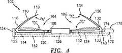
本開示の実施形態に従う、吻合装置100が、図1〜12に示される。吻合装置100は、前立腺全摘出術手順に対する有意な利点をもたらすが、このデバイスは、2つの身体の脈管が、一緒にされ、そして接続される、任意の吻合手順における用途に適用可能であることが理解される。 An anastomosis device 100 according to an embodiment of the present disclosure is shown in FIGS. Although the anastomosis device 100 provides significant advantages over a radical prostatectomy procedure, the device is applicable for use in any anastomosis procedure where two body vessels are brought together and connected. It is understood.
図1〜6に示されるように、吻合装置100は、挿入スリーブ180(図7)の管腔184の周りに、半径方向に取り付けられた、少なくとも1つの留め具102、好ましくは、複数の留め具102を備える。各留め具102は、第1の留め具部分104と第2の留め具部分106とを備える。留め具102の第1の留め具部分104は、ロッキング脚部分108および、ロッキング脚部分108と一体的に形成された係留脚部分110を備える。特に、ロッキング脚部分108は、近位端112および遠位端114を備え、ここから、係留脚部分110が延びる。係留脚部分110は、ロッキング脚部分108の遠位端114に一体的に連結された遠位端116と、鋭利な近位先端部118とを備える。望ましくは、係留脚部分110の鋭利な近位先端部118は、ロッキング脚部分108の近位端112に向かって方向付けられる。係留脚部分110は、鋭利な近位先端ウ118がロッキング脚部分108から間隔を空けられている第1の位置「A」を有し、そして、(図2および図3に想像で示されるように)鋭利な近位先端部118がロッキング脚部分108に近接している第2の位置「C」に折りたたまれ得る。 As shown in FIGS. 1-6, the anastomosis device 100 includes at least one
好ましくは、第1の留め具部分104のロッキング脚部分108は、第2の留め具部分106を係合するための固定要素を備える。特定の実施形態における固定要素は、その側部に沿って形成され、近位端112から遠位端114に向かって延びる一連の突出部120を含む。留め具102の第1の留め具部分104は、好ましくは、ロッキング脚部分108の遠位端110から遠位に突出するリップ122をさらに備える。 Preferably, the locking
留め具102の第2の留め具部分106は、ロッキング脚部分124と、ロッキング脚部分124と一体的に形成される係留脚部分126とを備える。特に、ロッキング脚部分124は、遠位端128と、近位端130とを備え、ここから、係留脚部分126が延びる。係留脚部分126は、ロッキング脚部分124の近位端130に一体的に連結された近位端132と、鋭利な遠位先端部134とを備える。望ましくは、係留脚部分126の鋭利な遠位先端部134は、ロッキング脚部分124の遠位端128に向かって方向付けられる。係留脚部分126は、鋭利な先端部134がロッキング脚部分124の遠位端128から間隔を空けている、第1の位置「A」を有し、そして、(図2および図4に想像で示されるように)鋭利な遠位先端部124がロッキング脚部分124に近接している第2の位置「C」に折りたたまれ得る。 The
好ましくは、第2の留め具部分106のロッキング脚部分124は、その側部表面に沿って形成されるロッキング路136を備える。図6に示されるように、ロッキング路136は、ロッキング脚部分124の上側表面から延びる上側壁138、固定脚124の下側表面から延びる下側壁140、ならびに、上側壁138の終端と下側壁140の終端との間に延びる、相互接続する側壁142により規定される。ロッキング路136は、少なくとも1つ、望ましくは、複数の、第1の留め具部分104の固定要素を係合するための固定要素を備える。示されるロッキング路136は、相互接続する側壁142の内部表面に沿って形成され、ロッキング脚部分124に向かって方向付けられる、複数の突出部144の形態の固定要素を有する。ロッキング路136は、そこを通る第1の留め具部分104の端部をスライド可能に受け取るようなサイズであり、寸法決めされる。特に、第1の留め具部分104のロッキング脚部分108が、第2の留め具部分106のロッキング路136に挿入される場合、ロッキング脚部分108の突出部120は、ロッキング路136の突出部144を係合し、それにより、留め具102の第1の留め具部分104を、留め具102の第2の留め具部分106に関する位置に効果的に固定する。 Preferably, the locking
留め具102の第1の留め具部分104と同様に、留め具102の第2の留め具部分106は、ロッキング脚部分124の近位端130から近位に突出するリップ148を備える。 Similar to the
図5に示されるように、ロッキング脚部分108の突出部120と、ロッキング路136の側壁142の突出部144は、それぞれ、ロッキング脚部分108がロッキング路136内に挿入されることを可能にし、そこからのロッキング脚部分18の引き抜きを妨害するように構成および適合された、歯様(例えば、鋸歯状)突出部146a、146bであることが意図される。特に、突出部146a、146bは、ロッキング脚部分108が方向「D」にスライドすることを可能にするように構成および適合され、一方で、ロッキング路136は、方向「E」のスライドを可能にされる。しかし、いったん突出部146aと突出部146bとが互いに係合すると、突出部146a、146bは、ロッキング脚部分108が方向「D」と逆方向にスライドするのを防ぎ、ロッキング路136が「E」の逆方向にスライドするのを防ぐ。言い換えると、突出部146a、146bは、ロッキング路136に対するロッキング脚部分108の一方向性の動きを可能にし、次いで、第2の留め具部分106に対する第1の留め具部分104の一方向性の動きを可能にするように構成および適合される。 As shown in FIG. 5, the
ロッキング脚部分108の突出部120とロッキング路136が示され、それぞれ、第1の留め具部分104と第2の留め具部分106の側部表面に沿って形成されるように記載されるが、突出部120が第1の留め具部分104のロッキング脚部分108の任意の表面に沿って提供され得、そして、ロッキング路136が第2の留め具部分106のロッキング脚部分124の任意の表面に沿って提供され得ることが想定され、これは本開示の範囲内である。 Although the
留め具102の第1の留め具部分104と第2の留め具部分106は、任意の外科的グレードの材料(例えば、ステンレス鋼またはチタン)から構成され得る。第1の留め具部分104および第2の留め具部分106は、好ましくは、医療グレードの生体吸収性材料(例えば、ポリグリコール酸(PGA)および/またはポリ乳酸(PLA))から構成されることが想定される。好ましくは、留め具102の材料および寸法は、留め具102が、吻合部位の適切な治癒を補償するのに十分な期間、その構造的な一体性を保持しつつ、所定の時間の後に溶解するように選択される。 The
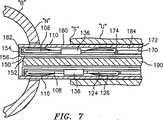
図7に想像で示されるように、吻合装置100は、第1の部材または金床150、第2の部材またはプッシャー170、および、留め具102を挿入スリーブ180内に取り付けるための軸190を備える。金床150およびプッシャー170は、図3および図4に想像で示される。金床150は、細長い本体部分152とその遠位端156に形成されるフック154を備える。金床150のフック154は、留め具102の第1の留め具部分104のリップ120を係合するように構成および適合される。プッシャー170は、細長い本体部分172とその遠位端176に形成される間隙174を備える。プッシャー170の間隙174は、留め具102の第2の留め具部分106のリップ146を係合するように構成および適合される。 As imaginarily shown in FIG. 7, the anastomosis device 100 includes a first member or
図7〜11に示されるように、挿入スリーブ180は、遠位端182、近位端(示さず)を備え、そこを通って延び、中心軸を規定する管腔184を規定する。軸190は、挿入スリーブ180の管腔184にスライド可能に受けられるように構成および適合される。軸190が、その中に形成される、複数の半径方向に方向付けられた、長軸方向に伸びる溝(示さず)を備えることが想定される。従って、軸190の各溝は、それぞれの金床150、プッシャー170および留め具102を受けるように構成および適合され得る。好ましくは、軸190は、軸190がスリーブ180内に挿入される場合に、第1の留め具部分104の係留脚部分108と、第2の留め具部分106の係留脚部分124が第2の位置「C」にあるような大きさにされる(図7を参照のこと)。 As shown in FIGS. 7-11, the
金床150およびプッシャー170は、フック154と間隙174との間に留め具102を受け取るための間隙を形成するように、互いに関して並べられる。留め具102は、この間隙に配置され、その結果、第1の留め具部分104と第2の留め具部分106が、互いに係合し、係留脚部分が互いに向かって進む余地を与える。複数の留め具102が挿入スリーブ180内に配置され、軸190が、留め具102とその対応する金床およびプッシャーとの間に配置される(図7を参照のこと)。
ここで、前立腺全摘出術吻合の実施における、吻合装置100の好ましい使用方法および操作方法は、図1〜12、特に図7を参照して、より詳細に記載される。吻合装置100は、恥骨後前立腺切除アプローチもしくは会陰前立腺切除アプローチ、または、膀胱および尿道が接近されなければならない任意のアプローチのいずれかにおいて使用され得る。前立腺が取り除かれると、公知の外科的技術を用いて、膀胱「B」の内部粘膜上皮をめくり返し、それを膀胱「B」の外側壁に縫合することによって、膀胱「B」の膀胱頚部「N」がまず再構築される。同様に、公知の外科的技術を用いて、尿道断端「S」の内部粘膜上皮をめくり返し、尿道「U」の外側壁に縫合することによって、尿道「U」の尿道断端「S」が再構築される。 Here, a preferred method of use and operation of the anastomosis device 100 in performing a radical prostatectomy anastomosis will be described in more detail with reference to FIGS. The anastomosis device 100 can be used in either a retropubic prostatectomy or perineal prostatectomy approach, or any approach where the bladder and urethra must be accessed. Once the prostate gland is removed, the bladder mucosa of bladder “B” is “turned to the bladder neck” by flipping the internal mucosal epithelium of bladder “B” and stitching it to the outer wall of bladder “B” using known surgical techniques. N "is first reconstructed. Similarly, using known surgical techniques, the internal mucosal epithelium of the urethral stump “S” is flipped over and sutured to the outer wall of the urethra “U” to create a urethral stump “S” of the urethra “U”. Is rebuilt.
好ましくは、膀胱頚部「N」が再構築されると、標準的なテニスラケット型閉鎖(すなわち、膀胱頚部の開口部が、テニスラケットの頭部を構成し、膀胱頚部から延びる半径方向の切開がテニスラケットの柄部分を構成する)を用いて、膀胱頚部「N」が、スリーブ180の遠位端180を膀胱「B」内に適切に収容し、保持するような大きさにされる。膀胱頚部の大きさは、患者によって変化する。代表的には、膀胱頚部「N」は、直径約7〜8mmであるような大きさにされる。 Preferably, when the bladder neck “N” is reconstructed, a standard tennis racket type closure (ie, the opening of the bladder neck constitutes the head of the tennis racket and a radial incision extending from the bladder neck is made). The bladder neck “N” is sized to properly house and hold the
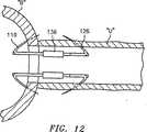
膀胱頚部「N」が再構築されると、装置100は、図7に示されるように、挿入スリーブ180の遠位端182が、尿道断端「S」から外に、そして、膀胱頚部「N」を通って膀胱「B」内まで延びるまで、経尿道的に尿道「U」を通って、通過する。 When the bladder neck “N” is reconstructed, the device 100 is configured so that the
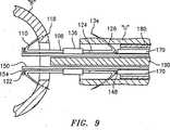
装置100がこのように位置付けられると、挿入スリーブ180が近位の方向に回収され、第1の留め具部分104の鋭利な近位先端部118を露出する。係留脚部分110は、第1の位置「A」まで偏らせられ、その結果、鋭利な近位先端部118が挿入スリーブ180内から露出される場合に、第1の留め具部分104の係留脚部分110が第1の位置「A」に展開される(図8を参照のこと)。係留脚部分110が展開されると、金床150のフック154が近位方向に回収され、第1の留め具部分104のリップ122を係合し、膀胱「B」の壁を通って鋭利な近位先端部118を押し出す。図9を参照のこと。 When the device 100 is so positioned, the
図9に示されるように、挿入スリーブ180は、第2の留め具部分106の鋭利な遠位先端部134と係留脚部分126が露出されるまで、近位方向にさらに回収される。係留脚部分126は、第1の位置「A」まで偏らせられ、その結果、係留脚部分126が挿入スリーブ180内から完全に露出される場合、第2の留め具部分106の係留脚部分126が第1の位置「A」まで展開される(図9を参照のこと)。係留脚部分126が展開されると、プッシャー170が遠位方向に進められてリップ148を係合し、尿道断端「S」の壁を通して鋭利な遠位先端部134を押し出す。 As shown in FIG. 9, the
第1の留め具部分104の鋭利な近位先端部118が膀胱「B」の壁を貫入し、鋭利な遠位先端部134が尿道断端「S」の壁を貫入すると、金床150のフック154がプッシャー170の間隙174に向かって接近し、それによって、第1の留め具部分104の係留脚部分110と、第2の留め具部分106の係留脚部分126とが互いに接近する。同時に、係留脚部分110と126とが互いに向かって接近するので、膀胱頚部「N」は、尿道断端「S」に向かって接近する(図10を参照のこと)。本開示に従って、係留脚110および126の互いに向かう接近は、結果として、突出部120と144とを互いに付加的に係合し、係留脚126に対する係留脚110の位置を維持する。従って、突出部120および144は、膀胱「B」が尿道「U」から離れるのを防ぐ。 When the sharp
膀胱頚部「N」が尿道断端「S」に向かって接近した後、プッシャー170と軸190が挿入スリーブ180から回収され、金床150がリップ122から解放される(図11を参照のこと)。その後、金床150と挿入スリーブ180が尿道「U」から回収される。 After bladder neck “N” approaches toward urethral stump “S”,
本開示に従う、留め具200の代替的な実施形態が図13Aおよび13Bに示される。上記の留め具102とは異なり、留め具200は、第1の留め具部分202および第2の留め具部分204を備える。第1の留め具部分202は、ロッキング脚部分206と、ロッキング脚部分206の近位端に旋回可能に連結された係留脚部分208とを備える。示される実施形態において、係留脚部分208は、旋回ピン210によってロッキング脚部分206に旋回可能に連結されているが、当該分野で公知の他の手段もまた使用され得る。あるいは、ロッキング脚部分206または係留脚部分208は、ロッキング脚部分206または係留脚部分208の他方に形成される開口部に受けられるように外側に延びる、一体的に形成されたピンを備え得る。第1の留め具部分202は、係留脚部分208を引き、係留脚部分208の遠位端をロッキング脚部分206から持ち上げる(例えば、第1の位置「A」から第2の位置「C」まで)ための係留脚部分208に接続される縫合糸212を備える。ロッキング脚部分206の近位端が、係留脚部分208の所定の量を超える持ち上げを停止するための止め(示さず)を備えることが意図される。 An alternative embodiment of a
図13Bに示されるように、第2の留め具部分204は、ロッキング脚部分214と、旋回ピン218によりロッキング脚部分214の遠位端に旋回可能に連結された係留脚部分216とを備える。あるいは、ロッキング脚部分214または係留脚部分216は、一体的に形成されたピンを備え得、このピンは、ロッキング脚部分214または係留脚部分216の他方に形成される開口部に受けられるために、外側に延びる。第2の留め具部分204はさらに、係留脚部分216に接続された縫合糸220を備え、この縫合糸220は、係留脚部分216を引き、ロッキング脚部分214から係留脚部分216の近位端を持ち上げる(例えば、第1の位置「A」から第2の位置「C」まで)ために、ロッキング脚部分214の遠位端の周囲を延びる。ロッキング脚部分214の遠位端が、係留脚部分216の所定の量を超える持ち上げを停止するための止め(示さず)を備えることが意図される。 As shown in FIG. 13B, the
本開示に従う装置が、前立腺全摘出術手順と組み合せて用いられるように記載されているが、同様の構造および操作様式を有する装置が、種々の他の外科手順において使用され得ることが想定される。種々の改変が、本明細書中に開示される、本開示の吻合デバイスおよび方法の実施形態になされ得ることが理解される。例えば、1つ以上の留め具が、挿入スリーブの中に並べられ得る。さらなる実施形態において、挿入スリーブは、位置「C」まで折りたたませるための係留脚部分を必要としない留め具を収容するような大きさである。この留め具は、波型の部分、蝶番のある部分、または折りたたみ可能な部分を有する単一のパーツを含み得る。留め具は、特定の実施形態において、別個のパーツを含む固定要素を含む。 Although a device according to the present disclosure has been described for use in combination with a total prostatectomy procedure, it is envisioned that a device having a similar structure and mode of operation can be used in a variety of other surgical procedures. . It will be understood that various modifications may be made to the embodiments of the disclosed anastomosis devices and methods disclosed herein. For example, one or more fasteners can be arranged in the insertion sleeve. In a further embodiment, the insertion sleeve is sized to accommodate a fastener that does not require a tether leg portion to fold to position “C”. The fastener may include a single part having a corrugated part, a hinged part, or a foldable part. The fastener includes, in certain embodiments, a securing element that includes separate parts.
従って、上記の説明は、限定するものとしてではなく、単なる好ましい実施形態の例示として考えられるべきである。当業者は、本開示の範囲内で他の改変を想定する。 Therefore, the above description should not be construed as limiting, but merely as exemplifications of preferred embodiments. Those skilled in the art will envision other modifications within the scope of this disclosure.
Claims (11)
Translated fromJapanese少なくとも1つの留め具であって、該留め具は、以下;
係留脚部分を備える第1の留め具部分;
係留脚部分を備える第2の留め具部分;
を備え、該第1および該第2の留め具部分は、該第1の止め具部分と該第2の留め具部分の位置を互いに関して選択的に固定するために、互いに関して作動可能である、留め具;
該第1の留め具部分を係合するように構成および適合されている金床(150);および
該第2の留め具部分を係合するように構成および適合されているプッシャー(170)
を備え、該金床および該プッシャーが、互いに関して移動可能であり、該第1の留め具部分と第2の留め具部分が、互いに関して移動し、
ここで、該第1および第2の留め具部分の係留脚部分の各々が、鋭利な先端を備え、ここで、該鋭利な先端は、実質的に互いに向かって方向付けられている、
装置。A device for bringing body vessels closertogether , the device being:
At least one fastener, the fastener comprising:
A first fastener portion comprising a mooring leg portion;
A second fastener portion comprising a mooring leg portion;
The first and second fastener portions are operable relative to each other to selectively secure the position of the first and second fastener portions relative to each other ,Fastener;
Ananvil (150) configured and adapted to engage the first fastener portion; and apusher (170) configured and adapted to engage the second fastener portion
The provided, saidanvil and saidpusher being movable with respect to each other, the fastener portion and a second fastener portion of the first ismoved with respect to each other,
Wherein each of the anchoring leg portions of the first and second fastener portions comprises a sharp tip, wherein the sharp tips are substantially directed toward each other;
apparatus.
前記第1の留め具部分の表面に沿って形成される一連の突出部;および
前記第2の留め具部分の表面に沿って形成されるロッキング路
を備え、該ロッキング路は、その中に該第1の留め具部分の前記ロッキング脚部分の端部を受け取るように構成および寸法決めされ、該ロッキング路は、その内部表面から延びる少なくとも1つの突出部を備え、該少なくとも1つの突出部は、該第1の留め具部分の表面にそって形成される該一連の突出部を係合するように構成および寸法決めされる、装置。6. The device according to claim5 , wherein the fixing element is:
A series of protrusions formed along the surface of the first fastener portion; and a locking path formed along the surface of the second fastener portion, the locking path therein Configured and dimensioned to receive an end of the locking leg portion of the first fastener portion, the locking path comprising at least one protrusion extending from an inner surface thereof, the at least one protrusion being An apparatus configured and dimensioned to engage the series of protrusions formed along the surface of the first fastener portion.
Applications Claiming Priority (2)
| Application Number | Priority Date | Filing Date | Title |
|---|---|---|---|
| US39010602P | 2002-06-19 | 2002-06-19 | |
| PCT/US2003/019516WO2004000138A1 (en) | 2002-06-19 | 2003-06-19 | Method and apparatus for anastomosis |
Publications (2)
| Publication Number | Publication Date |
|---|---|
| JP2005529716A JP2005529716A (en) | 2005-10-06 |
| JP4384033B2true JP4384033B2 (en) | 2009-12-16 |
Family
ID=30000514
Family Applications (1)
| Application Number | Title | Priority Date | Filing Date |
|---|---|---|---|
| JP2004516032AExpired - Fee RelatedJP4384033B2 (en) | 2002-06-19 | 2003-06-19 | Method and apparatus for anastomosis |
Country Status (8)
| Country | Link |
|---|---|
| US (3) | US7666197B2 (en) |
| EP (1) | EP1519687B1 (en) |
| JP (1) | JP4384033B2 (en) |
| AU (1) | AU2003245606B2 (en) |
| CA (1) | CA2489508C (en) |
| DE (1) | DE60331068D1 (en) |
| ES (1) | ES2339544T3 (en) |
| WO (1) | WO2004000138A1 (en) |
Families Citing this family (116)
| Publication number | Priority date | Publication date | Assignee | Title |
|---|---|---|---|---|
| US7510560B2 (en)* | 2002-06-20 | 2009-03-31 | Tyco Healthcare Group Lp | Method and apparatus for anastomosis including an anchoring sleeve |
| AU2003237077A1 (en)* | 2002-06-20 | 2004-01-06 | Tyco Healthcare Group, Lp | Method and apparatus for anastomosis including an anchoring sleeve |
| US9307991B2 (en) | 2002-08-22 | 2016-04-12 | Ams Research, Llc | Anastomosis device and related methods |
| US8551126B2 (en) | 2002-08-22 | 2013-10-08 | Ams Research Corporation | Anastomosis device and related methods |
| US8764775B2 (en)* | 2002-08-22 | 2014-07-01 | Ams Research Corporation | Anastomosis device and related methods |
| JP2007535342A (en) | 2004-03-11 | 2007-12-06 | パーキュテイニアス カルディオバスキュラー ソリューションズ ピー・ティー・ワイ リミテッド | Percutaneous prosthetic heart valve |
| US8636756B2 (en) | 2005-02-18 | 2014-01-28 | Ams Research Corporation | Anastomosis device and surgical tool actuation mechanism configurations |
| US9549739B2 (en) | 2005-05-20 | 2017-01-24 | Neotract, Inc. | Devices, systems and methods for treating benign prostatic hyperplasia and other conditions |
| US7771443B2 (en) | 2005-05-20 | 2010-08-10 | Ams Research Corporation | Anastomosis device approximating structure configurations |
| US8628542B2 (en) | 2005-05-20 | 2014-01-14 | Neotract, Inc. | Median lobe destruction apparatus and method |
| US7717928B2 (en) | 2005-05-20 | 2010-05-18 | Ams Research Corporation | Anastomosis device configurations and methods |
| US8603106B2 (en) | 2005-05-20 | 2013-12-10 | Neotract, Inc. | Integrated handle assembly for anchor delivery system |
| US7758594B2 (en) | 2005-05-20 | 2010-07-20 | Neotract, Inc. | Devices, systems and methods for treating benign prostatic hyperplasia and other conditions |
| US10925587B2 (en) | 2005-05-20 | 2021-02-23 | Neotract, Inc. | Anchor delivery system |
| US8668705B2 (en) | 2005-05-20 | 2014-03-11 | Neotract, Inc. | Latching anchor device |
| US7645286B2 (en) | 2005-05-20 | 2010-01-12 | Neotract, Inc. | Devices, systems and methods for retracting, lifting, compressing, supporting or repositioning tissues or anatomical structures |
| US10195014B2 (en) | 2005-05-20 | 2019-02-05 | Neotract, Inc. | Devices, systems and methods for treating benign prostatic hyperplasia and other conditions |
| US20070102170A1 (en)* | 2005-11-09 | 2007-05-10 | Waldack Larry E | Crimp Hub for Anastomosis Device |
| CA2881760C (en) | 2005-11-10 | 2017-06-13 | Arshad Quadri | Balloon-expandable, self-expanding, vascular prosthesis connecting stent |
| US20070156175A1 (en)* | 2005-12-29 | 2007-07-05 | Weadock Kevin S | Device for attaching, relocating and reinforcing tissue and methods of using same |
| US8066725B2 (en) | 2006-10-17 | 2011-11-29 | Ams Research Corporation | Anastomosis device having improved safety features |
| US7993264B2 (en) | 2006-11-09 | 2011-08-09 | Ams Research Corporation | Orientation adapter for injection tube in flexible endoscope |
| US8277466B2 (en) | 2006-11-14 | 2012-10-02 | Ams Research Corporation | Anastomosis device and method |
| US8491525B2 (en)* | 2006-11-17 | 2013-07-23 | Ams Research Corporation | Systems, apparatus and associated methods for needleless delivery of therapeutic fluids |
| US20080167526A1 (en)* | 2007-01-08 | 2008-07-10 | Crank Justin M | Non-Occlusive, Laterally-Constrained Injection Device |
| ATE514386T1 (en)* | 2007-02-28 | 2011-07-15 | Wilson Cook Medical Inc | INTESTINAL BYPASS USING MAGNETS |
| IL182155A0 (en)* | 2007-03-25 | 2007-07-24 | Nir Lilach | Anastomosis suturing device and methods thereof |
| US9504469B2 (en) | 2007-06-18 | 2016-11-29 | Asfora Ip, Llc | Vascular anastomosis device and method |
| US8361092B1 (en)* | 2007-06-18 | 2013-01-29 | Wilson T. Asfora | Vascular anastomosis device and method |
| US10004507B2 (en) | 2007-06-18 | 2018-06-26 | Asfora Ip, Llc | Vascular anastomosis device and method |
| US20130197546A1 (en) | 2007-08-02 | 2013-08-01 | Bioconnect Systems, Inc. | Implantable flow connector |
| EP2173259A4 (en) | 2007-08-02 | 2015-07-08 | Bio Connect Systems | Implantable flow connector |
| US8382761B2 (en)* | 2007-08-29 | 2013-02-26 | Covidien Lp | Surgical staple with adjustable width backspan |
| US7850649B2 (en) | 2007-11-09 | 2010-12-14 | Ams Research Corporation | Mechanical volume control for injection devices |
| WO2009132111A1 (en)* | 2008-04-23 | 2009-10-29 | Wilson-Cook Medical Inc. | Tacking device |
| US20100030139A1 (en)* | 2008-07-30 | 2010-02-04 | Copa Vincent G | Anastomosis Devices and Methods Utilizing Colored Bands |
| US20110118767A1 (en)* | 2008-07-30 | 2011-05-19 | Ams Research Corporation | Method and Apparatus for Determining Status of Approximation Structures on Anastomosis Device |
| WO2010022060A1 (en)* | 2008-08-19 | 2010-02-25 | Wilson-Cook Medical Inc. | Apparatus for removing lymph nodes or anchoring into tissue during a translumenal procedure |
| EP2328482B1 (en)* | 2008-08-29 | 2012-09-26 | Cook Medical Technologies LLC | Stapling device for closing perforations |
| US8192461B2 (en)* | 2008-09-11 | 2012-06-05 | Cook Medical Technologies Llc | Methods for facilitating closure of a bodily opening using one or more tacking devices |
| CN102292053A (en)* | 2008-09-29 | 2011-12-21 | 卡迪尔克阀门技术公司 | Heart valve |
| AU2009324819B2 (en) | 2008-12-09 | 2014-04-17 | Cook Medical Technologies Llc | Retractable tacking device |
| CA2746213A1 (en)* | 2008-12-09 | 2010-07-08 | Wilson-Cook Medical Inc. | Apparatus and methods for controlled release of tacking devices |
| EP2389122B1 (en)* | 2008-12-19 | 2015-03-04 | Cook Medical Technologies LLC | Clip devices |
| JP2012512715A (en)* | 2008-12-19 | 2012-06-07 | クック メディカル テクノロジーズ エルエルシー | A tacking device of varying thickness and method of delivery and deployment thereof |
| WO2010081029A1 (en) | 2009-01-08 | 2010-07-15 | Rotation Medical, Inc. | Implantable tendon protection systems and related kits and methods |
| US8388349B2 (en)* | 2009-01-14 | 2013-03-05 | Ams Research Corporation | Anastomosis deployment force training tool |
| US9179910B2 (en) | 2009-03-20 | 2015-11-10 | Rotation Medical, Inc. | Medical device delivery system and method |
| CA2961053C (en) | 2009-04-15 | 2019-04-30 | Edwards Lifesciences Cardiaq Llc | Vascular implant and delivery system |
| JP2012527970A (en)* | 2009-05-28 | 2012-11-12 | クック メディカル テクノロジーズ エルエルシー | Hail-fastening device and hail-fastening device deployment method |
| AU2010256472B2 (en) | 2009-06-04 | 2015-07-09 | Rotation Medical, Inc. | Apparatus for fixing sheet-like materials to a target tissue |
| CA2763937C (en) | 2009-06-04 | 2017-05-23 | Rotation Medical, Inc. | Methods and apparatus for deploying sheet-like materials |
| WO2010151382A1 (en) | 2009-06-26 | 2010-12-29 | Wilson-Cook Medical Inc. | Linear clamps for anastomosis |
| DE102009036365A1 (en)* | 2009-08-06 | 2011-02-10 | Norbert Lemke | Surgical clip for sealing intracorporal vessel or tissue opening, has jaw supported in longitudinal movable manner relative to connection element and lockable using clamping force along connection element in self-locking manner |
| US8652203B2 (en) | 2010-09-23 | 2014-02-18 | Cardiaq Valve Technologies, Inc. | Replacement heart valves, delivery devices and methods |
| US9730790B2 (en) | 2009-09-29 | 2017-08-15 | Edwards Lifesciences Cardiaq Llc | Replacement valve and method |
| US8545525B2 (en) | 2009-11-03 | 2013-10-01 | Cook Medical Technologies Llc | Planar clamps for anastomosis |
| US9198750B2 (en) | 2010-03-11 | 2015-12-01 | Rotation Medical, Inc. | Tendon repair implant and method of arthroscopic implantation |
| US8603121B2 (en) | 2010-04-14 | 2013-12-10 | Cook Medical Technologies Llc | Systems and methods for creating anastomoses |
| EP2558004A4 (en)* | 2010-04-16 | 2015-04-29 | Univ Utah Res Found | METHODS, DEVICES, AND APPARATUS FOR REALIZING VASCULAR ANASTOMOSIS |
| US8579964B2 (en) | 2010-05-05 | 2013-11-12 | Neovasc Inc. | Transcatheter mitral valve prosthesis |
| US8747386B2 (en) | 2010-12-16 | 2014-06-10 | Ams Research Corporation | Anastomosis device and related methods |
| US10952783B2 (en) | 2011-12-29 | 2021-03-23 | Rotation Medical, Inc. | Guidewire having a distal fixation member for delivering and positioning sheet-like materials in surgery |
| WO2012145059A1 (en) | 2011-02-15 | 2012-10-26 | Rotation Medical, Inc. | Methods and apparatus for fixing sheet-like materials to a target tissue |
| WO2012112565A2 (en) | 2011-02-15 | 2012-08-23 | Rotation Medical, Inc. | Methods and apparatus for delivering and positioning sheet-like materials |
| WO2012129234A1 (en)* | 2011-03-21 | 2012-09-27 | Endo Pharmaceuticals Inc. | Urethral anastomosis device and method |
| US9554897B2 (en) | 2011-04-28 | 2017-01-31 | Neovasc Tiara Inc. | Methods and apparatus for engaging a valve prosthesis with tissue |
| US9308087B2 (en) | 2011-04-28 | 2016-04-12 | Neovasc Tiara Inc. | Sequentially deployed transcatheter mitral valve prosthesis |
| US9060749B2 (en) | 2011-08-12 | 2015-06-23 | Boston Scientific Scimed, Inc. | Methods, compositions and kits for performing anastomosis procedures in conjunction with a radical prostatectomy procedure |
| US9271726B2 (en) | 2011-12-19 | 2016-03-01 | Rotation Medical, Inc. | Fasteners and fastener delivery devices for affixing sheet-like materials to bone or tissue |
| US9107661B2 (en) | 2011-12-19 | 2015-08-18 | Rotation Medical, Inc. | Fasteners and fastener delivery devices for affixing sheet-like materials to bone or tissue |
| EP2793712B1 (en) | 2011-12-19 | 2018-03-28 | Rotation Medical, Inc. | Fasteners for affixing sheet -like materials to bone or tissue |
| AU2012355433B2 (en) | 2011-12-19 | 2016-10-20 | Rotation Medical, Inc. | Apparatus and method for forming pilot holes in bone and delivering fasteners therein for retaining an implant |
| WO2013101641A2 (en) | 2011-12-29 | 2013-07-04 | Rotation Medical, Inc. | Anatomical location markers and methods of use in positioning sheet-like materials during surgery |
| EP2797532B1 (en) | 2011-12-29 | 2016-04-06 | Rotation Medical, Inc. | Apparatus for delivering and positioning sheet-like materials in surgery |
| US9381335B2 (en) | 2012-03-21 | 2016-07-05 | Ams Research Corporation | Bladder wall drug delivery system |
| US10292801B2 (en) | 2012-03-29 | 2019-05-21 | Neotract, Inc. | System for delivering anchors for treating incontinence |
| US9314600B2 (en) | 2012-04-15 | 2016-04-19 | Bioconnect Systems, Inc. | Delivery system for implantable flow connector |
| EP2838440A1 (en)* | 2012-04-15 | 2015-02-25 | Bioconnect Systems Inc. | Implantable flow connector |
| US10434293B2 (en) | 2012-04-15 | 2019-10-08 | Tva Medical, Inc. | Implantable flow connector |
| AU2013251378A1 (en)* | 2012-04-26 | 2014-11-06 | Conmed Corporation | Tissue fixation system to grasp, retain and release tissue |
| US9089365B2 (en) | 2012-04-26 | 2015-07-28 | Imds Llc | Tissue fixation device |
| US9345573B2 (en) | 2012-05-30 | 2016-05-24 | Neovasc Tiara Inc. | Methods and apparatus for loading a prosthesis onto a delivery system |
| JP2014004016A (en)* | 2012-06-21 | 2014-01-16 | Olympus Corp | Access port |
| US10130353B2 (en) | 2012-06-29 | 2018-11-20 | Neotract, Inc. | Flexible system for delivering an anchor |
| CA2885352A1 (en)* | 2012-09-18 | 2014-03-27 | Endo Pharmaceuticals Inc. | Urethral anastomosis device and method |
| US10583002B2 (en) | 2013-03-11 | 2020-03-10 | Neovasc Tiara Inc. | Prosthetic valve with anti-pivoting mechanism |
| US9730791B2 (en) | 2013-03-14 | 2017-08-15 | Edwards Lifesciences Cardiaq Llc | Prosthesis for atraumatically grasping intralumenal tissue and methods of delivery |
| US9681951B2 (en) | 2013-03-14 | 2017-06-20 | Edwards Lifesciences Cardiaq Llc | Prosthesis with outer skirt and anchors |
| US9572665B2 (en) | 2013-04-04 | 2017-02-21 | Neovasc Tiara Inc. | Methods and apparatus for delivering a prosthetic valve to a beating heart |
| WO2015047132A1 (en)* | 2013-09-24 | 2015-04-02 | Сергей Александрович ГРИШАНКОВ | Method and device for forming surgical anastomoses |
| CA2945821C (en) | 2014-05-09 | 2018-09-04 | Rotation Medical, Inc. | Medical implant delivery system for sheet-like implant |
| WO2015181403A1 (en) | 2014-05-27 | 2015-12-03 | Fundación Tekniker | Apparatus for anastomosis |
| US10123796B2 (en) | 2014-11-04 | 2018-11-13 | Rotation Medical, Inc. | Medical implant delivery system and related methods |
| AU2015343273B2 (en) | 2014-11-04 | 2017-12-14 | Rotation Medical, Inc. | Medical implant delivery system and related methods |
| EP3215025B1 (en) | 2014-11-04 | 2020-12-23 | Rotation Medical, Inc. | Medical implant delivery system |
| JP2018507089A (en)* | 2015-03-04 | 2018-03-15 | エンドギア エルエルシー | Endoscopic clip |
| CA2983341A1 (en) | 2015-05-06 | 2016-11-10 | Rotation Medical, Inc. | Medical implant delivery system and related methods |
| US10265156B2 (en) | 2015-06-15 | 2019-04-23 | Rotation Medical, Inc | Tendon repair implant and method of implantation |
| US10639020B2 (en) | 2015-09-28 | 2020-05-05 | M-V Arterica AB | Vascular closure device |
| CN105640604B (en)* | 2015-12-25 | 2017-12-15 | 有研亿金新材料有限公司 | A kind of art medium vessels rapid abutting joint servicing unit |
| EP3397175B1 (en) | 2015-12-31 | 2021-11-24 | Rotation Medical, Inc. | Fastener delivery system |
| AU2016381936B2 (en) | 2015-12-31 | 2019-02-28 | Rotation Medical, Inc. | Medical implant delivery system and related methods |
| US10350062B2 (en) | 2016-07-21 | 2019-07-16 | Edwards Lifesciences Corporation | Replacement heart valve prosthesis |
| GB2554928A (en)* | 2016-10-14 | 2018-04-18 | Univ College Dublin Nat Univ Ireland Dublin | A tissue anchor and wound closure system |
| US11103239B2 (en)* | 2017-04-21 | 2021-08-31 | Biomet Manufacturing, Llc | Ratchet staple |
| KR101901651B1 (en)* | 2017-04-27 | 2018-10-01 | 울산대학교 산학협력단 | Surgical stent for reconstructing pancreatobiliary |
| US20190142403A1 (en) | 2017-11-16 | 2019-05-16 | M-V Arterica AB | Tissue closure device |
| US11179145B2 (en) | 2017-11-16 | 2021-11-23 | M-V Arterica AB | Collapsible tube for hemostasis |
| WO2019113292A1 (en) | 2017-12-07 | 2019-06-13 | Rotation Medical, Inc. | Medical implant delivery system and related methods |
| ES2953556T3 (en) | 2017-12-23 | 2023-11-14 | Teleflex Life Sciences Ltd | Expandable Tissue Docking Apparatus |
| SG11202006260XA (en)* | 2018-01-04 | 2020-07-29 | Seger Surgical Solutions Ltd | Tissue alignment for surgical closure |
| CN117481869A (en) | 2018-01-25 | 2024-02-02 | 爱德华兹生命科学公司 | Delivery system for assisting in recapture and repositioning of replacement valves after deployment |
| EP3870076A4 (en) | 2018-10-24 | 2022-08-10 | Arterica Inc. | SELF-EXPANDING HEMOSTATIC DEVICES AND METHODS FOR FASCIAL AND VASCULAR PASSAGES |
| EP4061244A4 (en) | 2019-11-19 | 2024-06-19 | Arterica Inc. | VASCULAR CLOSURE DEVICES AND METHODS |
| US20210393291A1 (en)* | 2020-01-21 | 2021-12-23 | Murray Rosenbaum | Transseptal puncture device |
Family Cites Families (61)
| Publication number | Priority date | Publication date | Assignee | Title |
|---|---|---|---|---|
| US2127903A (en)* | 1936-05-05 | 1938-08-23 | Davis & Geck Inc | Tube for surgical purposes and method of preparing and using the same |
| US4553543A (en)* | 1984-03-05 | 1985-11-19 | Amarasinghe Disamodha C | Suturing assembly and method |
| US4848367A (en)* | 1987-02-11 | 1989-07-18 | Odis L. Avant | Method of effecting dorsal vein ligation |
| US5478353A (en)* | 1987-05-14 | 1995-12-26 | Yoon; Inbae | Suture tie device system and method for suturing anatomical tissue proximate an opening |
| US4803984A (en)* | 1987-07-06 | 1989-02-14 | Montefiore Hospital Association Of Western Pennsylvania | Method for performing small vessel anastomosis |
| SU1616624A1 (en)* | 1987-07-14 | 1990-12-30 | Предприятие П/Я А-3697 | Surgical suturing apparatus |
| US4911164A (en)* | 1988-04-26 | 1990-03-27 | Roth Robert A | Surgical tool and method of use |
| US5425739A (en)* | 1989-03-09 | 1995-06-20 | Avatar Design And Development, Inc. | Anastomosis stent and stent selection system |
| US5035702A (en)* | 1990-06-18 | 1991-07-30 | Taheri Syde A | Method and apparatus for providing an anastomosis |
| US5366462A (en)* | 1990-08-28 | 1994-11-22 | Robert L. Kaster | Method of side-to-end vascular anastomotic stapling |
| US5047039A (en)* | 1990-09-14 | 1991-09-10 | Odis Lynn Avant | Method and apparatus for effecting dorsal vein ligation and tubular anastomosis and laparoscopic prostatectomy |
| US5122156A (en)* | 1990-12-14 | 1992-06-16 | United States Surgical Corporation | Apparatus for securement and attachment of body organs |
| US5312456A (en)* | 1991-01-31 | 1994-05-17 | Carnegie Mellon University | Micromechanical barb and method for making the same |
| GB9111972D0 (en)* | 1991-06-04 | 1991-07-24 | Clinical Product Dev Ltd | Medical/surgical devices |
| US5197649A (en)* | 1991-10-29 | 1993-03-30 | The Trustees Of Columbia University In The City Of New York | Gastrointestinal endoscoptic stapler |
| HU211761B (en)* | 1991-11-06 | 1995-12-28 | Cziffer | Approximator for single usual especially for the sawing and the replacement of damaged nerves |
| FR2685208B1 (en)* | 1991-12-23 | 1998-02-27 | Ela Medical Sa | VENTRICULAR CANNULA DEVICE. |
| US5234448A (en)* | 1992-02-28 | 1993-08-10 | Shadyside Hospital | Method and apparatus for connecting and closing severed blood vessels |
| US5540704A (en)* | 1992-09-04 | 1996-07-30 | Laurus Medical Corporation | Endoscopic suture system |
| US5364408A (en)* | 1992-09-04 | 1994-11-15 | Laurus Medical Corporation | Endoscopic suture system |
| US6048351A (en)* | 1992-09-04 | 2000-04-11 | Scimed Life Systems, Inc. | Transvaginal suturing system |
| US5578044A (en)* | 1992-09-04 | 1996-11-26 | Laurus Medical Corporation | Endoscopic suture system |
| US5713889A (en)* | 1992-10-20 | 1998-02-03 | Chang; Hau Hsien | Urethral stump carrier for radical retropubic prostatectomy |
| US5591206A (en)* | 1993-09-30 | 1997-01-07 | Moufarr+E,Gra E+Ee Ge; Richard | Method and device for closing wounds |
| DK145593A (en)* | 1993-12-23 | 1995-06-24 | Joergen A Rygaard | Surgical double instrument for performing connection mlm. arteries (end-to-side anastomosis) |
| US5486187A (en)* | 1994-01-04 | 1996-01-23 | Schenck; Robert R. | Anastomosis device and method |
| US5464415A (en)* | 1994-03-15 | 1995-11-07 | Chen; Te-Chuan | Sutureless intestinal anastomosis gun |
| US5540701A (en)* | 1994-05-20 | 1996-07-30 | Hugh Sharkey | Passive fixation anastomosis method and device |
| US5545171A (en)* | 1994-09-22 | 1996-08-13 | Vidamed, Inc. | Anastomosis catheter |
| US5554162A (en)* | 1994-12-02 | 1996-09-10 | Delange; Gregory S. | Method and device for surgically joining luminal structures |
| US5695504A (en)* | 1995-02-24 | 1997-12-09 | Heartport, Inc. | Devices and methods for performing a vascular anastomosis |
| US5904697A (en)* | 1995-02-24 | 1999-05-18 | Heartport, Inc. | Devices and methods for performing a vascular anastomosis |
| US5591179A (en)* | 1995-04-19 | 1997-01-07 | Applied Medical Resources Corporation | Anastomosis suturing device and method |
| JP3729861B2 (en)* | 1995-06-07 | 2005-12-21 | メッドトロニック・インコーポレイテッド | Wound closure device |
| AU3410095A (en)* | 1995-08-24 | 1997-03-19 | Inbae Yoon | Suture tie device system and method for suturing anatomical tissue proximate an opening |
| US5702412A (en)* | 1995-10-03 | 1997-12-30 | Cedars-Sinai Medical Center | Method and devices for performing vascular anastomosis |
| US5716370A (en)* | 1996-02-23 | 1998-02-10 | Williamson, Iv; Warren | Means for replacing a heart valve in a minimally invasive manner |
| US5980483A (en)* | 1996-05-21 | 1999-11-09 | Dimitri; Mauro | Drainage catheter for continent urinary neo-bladders |
| US6024748A (en)* | 1996-07-23 | 2000-02-15 | United States Surgical Corporation | Singleshot anastomosis instrument with detachable loading unit and method |
| US5833698A (en)* | 1996-07-23 | 1998-11-10 | United States Surgical Corporation | Anastomosis instrument and method |
| US5707380A (en)* | 1996-07-23 | 1998-01-13 | United States Surgical Corporation | Anastomosis instrument and method |
| US5868763A (en)* | 1996-09-16 | 1999-02-09 | Guidant Corporation | Means and methods for performing an anastomosis |
| US6149658A (en)* | 1997-01-09 | 2000-11-21 | Coalescent Surgical, Inc. | Sutured staple surgical fasteners, instruments and methods for minimally invasive vascular and endoscopic surgery |
| US5944730A (en)* | 1997-05-19 | 1999-08-31 | Cardio Medical Solutions, Inc. | Device and method for assisting end-to-side anastomosis |
| US6063114A (en)* | 1997-09-04 | 2000-05-16 | Kensey Nash Corporation | Connector system for vessels, ducts, lumens or hollow organs and methods of use |
| US5868762A (en)* | 1997-09-25 | 1999-02-09 | Sub-Q, Inc. | Percutaneous hemostatic suturing device and method |
| US6280460B1 (en)* | 1998-02-13 | 2001-08-28 | Heartport, Inc. | Devices and methods for performing vascular anastomosis |
| US5951576A (en)* | 1998-03-02 | 1999-09-14 | Wakabayashi; Akio | End-to-side vascular anastomosing stapling device |
| US6051007A (en)* | 1998-03-02 | 2000-04-18 | Corvascular, Inc. | Sternal closure device and instruments therefor |
| US6176864B1 (en)* | 1998-03-09 | 2001-01-23 | Corvascular, Inc. | Anastomosis device and method |
| WO1999047050A2 (en)* | 1998-03-20 | 1999-09-23 | Scimed Life Systems, Inc. | Endoscopic suture systems |
| US6080167A (en)* | 1998-04-28 | 2000-06-27 | Lyell; Mark S. | Anastomotic instrument |
| US6203553B1 (en)* | 1999-09-08 | 2001-03-20 | United States Surgical | Stapling apparatus and method for heart valve replacement |
| US6152937A (en)* | 1998-11-06 | 2000-11-28 | St. Jude Medical Cardiovascular Group, Inc. | Medical graft connector and methods of making and installing same |
| AU2003221976A1 (en) | 2002-04-16 | 2003-11-03 | Tyco Healthcare Group Lp | Method and apparatus for anastomosis including an expandable anchor |
| US20030229364A1 (en)* | 2002-06-11 | 2003-12-11 | Michael Seiba | Device for anastomosis in a radical retropubic prostatectomy |
| US8083804B2 (en) | 2002-06-19 | 2011-12-27 | Tyco Healthcare Group Lp | Method and apparatus for anastomosis including annular joining member |
| ES2356069T3 (en) | 2002-06-19 | 2011-04-04 | Tyco Healthcare Group Lp | APPARATUS FOR ANASTOMOSIS AFTER A RADICAL PROSTATECTOMY. |
| US7510560B2 (en) | 2002-06-20 | 2009-03-31 | Tyco Healthcare Group Lp | Method and apparatus for anastomosis including an anchoring sleeve |
| US7998155B2 (en) | 2002-06-20 | 2011-08-16 | Tyco Healthcare Group Lp | Method and apparatus for anastomosis including annular joining member |
| AU2003237077A1 (en) | 2002-06-20 | 2004-01-06 | Tyco Healthcare Group, Lp | Method and apparatus for anastomosis including an anchoring sleeve |
- 2003
- 2003-06-19JPJP2004516032Apatent/JP4384033B2/ennot_activeExpired - Fee Related
- 2003-06-19DEDE60331068Tpatent/DE60331068D1/ennot_activeExpired - Lifetime
- 2003-06-19WOPCT/US2003/019516patent/WO2004000138A1/enactiveApplication Filing
- 2003-06-19USUS10/516,434patent/US7666197B2/ennot_activeExpired - Fee Related
- 2003-06-19ESES03739235Tpatent/ES2339544T3/ennot_activeExpired - Lifetime
- 2003-06-19EPEP03739235Apatent/EP1519687B1/ennot_activeExpired - Lifetime
- 2003-06-19AUAU2003245606Apatent/AU2003245606B2/ennot_activeCeased
- 2003-06-19CACA2489508Apatent/CA2489508C/ennot_activeExpired - Fee Related
- 2009
- 2009-12-02USUS12/629,185patent/US8177799B2/ennot_activeExpired - Fee Related
- 2012
- 2012-04-09USUS13/442,118patent/US9066718B2/ennot_activeExpired - Fee Related
Also Published As
| Publication number | Publication date |
|---|---|
| US7666197B2 (en) | 2010-02-23 |
| EP1519687B1 (en) | 2010-01-20 |
| US20120197274A1 (en) | 2012-08-02 |
| US8177799B2 (en) | 2012-05-15 |
| AU2003245606B2 (en) | 2008-04-03 |
| JP2005529716A (en) | 2005-10-06 |
| US20050251155A1 (en) | 2005-11-10 |
| US20100082049A1 (en) | 2010-04-01 |
| EP1519687A1 (en) | 2005-04-06 |
| WO2004000138A1 (en) | 2003-12-31 |
| DE60331068D1 (en) | 2010-03-11 |
| CA2489508C (en) | 2011-03-29 |
| CA2489508A1 (en) | 2003-12-31 |
| AU2003245606A1 (en) | 2004-01-06 |
| US9066718B2 (en) | 2015-06-30 |
| ES2339544T3 (en) | 2010-05-21 |
Similar Documents
| Publication | Publication Date | Title |
|---|---|---|
| JP4384033B2 (en) | Method and apparatus for anastomosis | |
| CA2489507C (en) | Method and apparatus for anastomosis including an anchoring sleeve | |
| US7998155B2 (en) | Method and apparatus for anastomosis including annular joining member | |
| EP1524941B1 (en) | Apparatus for anastomosis including an anchoring sleeve | |
| US8328866B2 (en) | Method and apparatus for radical prostatectomy anastomosis including an anchor for engaging a body vessel and deployable sutures | |
| EP1615567B1 (en) | Apparatus for radical prostatectomy anastomosis including an anchor for engaging a body vessel and deployable sutures | |
| US8349019B2 (en) | Method and apparatus for anastomosis including annular joining member | |
| WO2004098417A1 (en) | Method and apparatus for radical prostatectomy anastomosis including an anchor for engaging a body vessel and deployable sutures | |
| AU2003279113B2 (en) | Method and apparatus for anastomosis including an anchoring sleeve |
Legal Events
| Date | Code | Title | Description |
|---|---|---|---|
| A621 | Written request for application examination | Free format text:JAPANESE INTERMEDIATE CODE: A621 Effective date:20060512 | |
| A131 | Notification of reasons for refusal | Free format text:JAPANESE INTERMEDIATE CODE: A131 Effective date:20090428 | |
| A521 | Request for written amendment filed | Free format text:JAPANESE INTERMEDIATE CODE: A523 Effective date:20090727 | |
| TRDD | Decision of grant or rejection written | ||
| A01 | Written decision to grant a patent or to grant a registration (utility model) | Free format text:JAPANESE INTERMEDIATE CODE: A01 Effective date:20090916 | |
| A01 | Written decision to grant a patent or to grant a registration (utility model) | Free format text:JAPANESE INTERMEDIATE CODE: A01 | |
| A61 | First payment of annual fees (during grant procedure) | Free format text:JAPANESE INTERMEDIATE CODE: A61 Effective date:20090924 | |
| FPAY | Renewal fee payment (event date is renewal date of database) | Free format text:PAYMENT UNTIL: 20121002 Year of fee payment:3 | |
| R150 | Certificate of patent or registration of utility model | Free format text:JAPANESE INTERMEDIATE CODE: R150 | |
| FPAY | Renewal fee payment (event date is renewal date of database) | Free format text:PAYMENT UNTIL: 20131002 Year of fee payment:4 | |
| R250 | Receipt of annual fees | Free format text:JAPANESE INTERMEDIATE CODE: R250 | |
| R250 | Receipt of annual fees | Free format text:JAPANESE INTERMEDIATE CODE: R250 | |
| LAPS | Cancellation because of no payment of annual fees |