JP4383878B2 - Communication system and communication method between wireless networks integrating a plurality of points - Google Patents
Communication system and communication method between wireless networks integrating a plurality of pointsDownload PDFInfo
- Publication number
- JP4383878B2 JP4383878B2JP2003548471AJP2003548471AJP4383878B2JP 4383878 B2JP4383878 B2JP 4383878B2JP 2003548471 AJP2003548471 AJP 2003548471AJP 2003548471 AJP2003548471 AJP 2003548471AJP 4383878 B2JP4383878 B2JP 4383878B2
- Authority
- JP
- Japan
- Prior art keywords
- network
- control device
- available physical
- devices
- physical area
- Prior art date
- Legal status (The legal status is an assumption and is not a legal conclusion. Google has not performed a legal analysis and makes no representation as to the accuracy of the status listed.)
- Expired - Fee Related
Links
Images


Classifications
- H—ELECTRICITY
- H04—ELECTRIC COMMUNICATION TECHNIQUE
- H04W—WIRELESS COMMUNICATION NETWORKS
- H04W8/00—Network data management
- H04W8/02—Processing of mobility data, e.g. registration information at HLR [Home Location Register] or VLR [Visitor Location Register]; Transfer of mobility data, e.g. between HLR, VLR or external networks
- H04W8/08—Mobility data transfer
- H—ELECTRICITY
- H04—ELECTRIC COMMUNICATION TECHNIQUE
- H04L—TRANSMISSION OF DIGITAL INFORMATION, e.g. TELEGRAPHIC COMMUNICATION
- H04L12/00—Data switching networks
- H04L12/28—Data switching networks characterised by path configuration, e.g. LAN [Local Area Networks] or WAN [Wide Area Networks]
- H—ELECTRICITY
- H04—ELECTRIC COMMUNICATION TECHNIQUE
- H04W—WIRELESS COMMUNICATION NETWORKS
- H04W52/00—Power management, e.g. Transmission Power Control [TPC] or power classes
- H04W52/04—Transmission power control [TPC]
- H04W52/38—TPC being performed in particular situations
- H04W52/46—TPC being performed in particular situations in multi-hop networks, e.g. wireless relay networks
- H—ELECTRICITY
- H04—ELECTRIC COMMUNICATION TECHNIQUE
- H04W—WIRELESS COMMUNICATION NETWORKS
- H04W92/00—Interfaces specially adapted for wireless communication networks
- H04W92/02—Inter-networking arrangements
- H—ELECTRICITY
- H04—ELECTRIC COMMUNICATION TECHNIQUE
- H04B—TRANSMISSION
- H04B1/00—Details of transmission systems, not covered by a single one of groups H04B3/00 - H04B13/00; Details of transmission systems not characterised by the medium used for transmission
- H04B1/69—Spread spectrum techniques
- H04B1/7163—Spread spectrum techniques using impulse radio
- H04B1/71632—Signal aspects
- H—ELECTRICITY
- H04—ELECTRIC COMMUNICATION TECHNIQUE
- H04W—WIRELESS COMMUNICATION NETWORKS
- H04W84/00—Network topologies
- H04W84/18—Self-organising networks, e.g. ad-hoc networks or sensor networks
- H—ELECTRICITY
- H04—ELECTRIC COMMUNICATION TECHNIQUE
- H04W—WIRELESS COMMUNICATION NETWORKS
- H04W88/00—Devices specially adapted for wireless communication networks, e.g. terminals, base stations or access point devices
- H04W88/02—Terminal devices
- H04W88/04—Terminal devices adapted for relaying to or from another terminal or user
- H—ELECTRICITY
- H04—ELECTRIC COMMUNICATION TECHNIQUE
- H04W—WIRELESS COMMUNICATION NETWORKS
- H04W92/00—Interfaces specially adapted for wireless communication networks
- H04W92/16—Interfaces between hierarchically similar devices
- H04W92/24—Interfaces between hierarchically similar devices between backbone network devices
Landscapes
- Engineering & Computer Science (AREA)
- Computer Networks & Wireless Communication (AREA)
- Signal Processing (AREA)
- Databases & Information Systems (AREA)
- Mobile Radio Communication Systems (AREA)
- Small-Scale Networks (AREA)
- Radio Relay Systems (AREA)
- Near-Field Transmission Systems (AREA)
Abstract
Description
Translated fromJapanese本発明は無線パーソナルエリアネットワーク及び無線ローカルエリアネットワークに関する。特に本発明は、複数の重なる又は隣接する無線パーソナルエリアネットワークまたは無線ローカルエリアネットワークの間の通信を容易にするシステム、方法、デバイス、及びコンピュータプログラム製品に関する。 The present invention relates to a wireless personal area network and a wireless local area network. In particular, the present invention relates to systems, methods, devices, and computer program products that facilitate communication between multiple overlapping or adjacent wireless personal area networks or wireless local area networks.
関連出願の相互参照
本文書は、「スカッタネットまたはマルチホップ・アドホック・ネットワーキング技術」と題する2001年11月28日出願の特許権の保有者が共通で、本願と同時係属中の米国仮出願第60/333,524号の優先日の利益を主張するものであり、この出願の内容は本明細書において参照されることにより本発明の開示に含まれる。Cross-reference to related applications This document is a US provisional application co-pending and co-pending with this patent application, entitled "Scutternet or multi-hop ad hoc networking technology". No. 60 / 333,524, which claims the benefit of the priority date, the contents of which are hereby incorporated by reference into the present disclosure.
国際標準化機構(International Standards Organization’s:ISO)が定める開放型システム間相互接続(Open Systems Interconnection:OSI)標準は、エンドユーザと物理デバイスとの間の7階層を提供し、これらの階層を通して種々のシステムが通信することができる。各層は種々のタスクを遂行する役割を担い、そしてOSI標準は階層間だけでなく、標準に準拠するデバイス間の相互作用を指定する。 The Open Systems Interconnection (OSI) standard defined by the International Standards Organizations (ISO) provides seven layers between end users and physical devices, and various through these layers. Systems can communicate. Each layer is responsible for performing various tasks, and the OSI standard specifies interactions between devices that conform to the standard as well as between layers.
図1は7層構造のOSI標準の階層を示している。図1からわかるように、OSI標準100は物理層110、データリンク層120、ネットワーク層130、トランスポート層140、セッション層150、プレゼンテーション層160、及びアプリケーション層170を含む。 FIG. 1 shows a seven-layer OSI standard hierarchy. As can be seen from FIG. 1, the OSI
物理(PHY)層110は、ビットストリームを電気的、機械的、機能的及び手続的の各レベルでネットワークを通して伝送する。この層はデータをキャリアで送受信するハードウェア手段となる。データリンク層120は、物理媒体におけるビット演算及び媒体におけるメッセージフォーマットを記述し、データブロック(フレームのような)を適切に同期をとって送信する。ネットワーキング層130は、正しい送信先に対するデータのルーティング及び転送を処理し、接続を維持し、そして終了させる。トランスポート層140は、エンドツーエンド制御及びエラーチェック操作を管理して確実にデータ転送を完結させる。セッション層150は、各エンドにおいてアプリケーション間の会話、交換及び対話をセットアップし、調整し、そして終了させる。プレゼンテーション層160は、着信及び発信データを一つのプレゼンテーションフォーマットから別のプレゼンテーションフォーマットに変換する。アプリケーション層170は、通信相手を識別し、サービス品質を確認し、ユーザ認証及びプライバシーを検討し、そしてデータ構文の全ての制約を確認するための層である。 The physical (PHY)
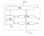
IEEE 802委員会は、ローカルネットワーク用にOSI標準100の物理層110及びデータリンク層120にほぼ対応する3層アーキテクチャを開発した。図2は、IEEE 802標準200を示している。 The IEEE 802 committee has developed a three-layer architecture that roughly corresponds to the
図2に示すように、IEEE 802標準200は、物理(PHY)層210、メディアアクセス制御(MAC)層220、及び論理リンク制御(LLC)層225を含む。PHY層210は、実質的にOSI標準100のPHY層110のように動作する。MAC層220及びLLC層225は、OSI標準100のデータリンク層120の機能を共有する。LLC層225は、データを、PHY層210で送受信することができるフレームに格納し、そしてMAC層220はデータリンクを通して通信を管理して、データフレームを送信し、そしてアクノリッジメント(ACK)フレームを受信する。MAC層220及びLLC層225は、共同してエラーチェックを行なうだけでなく、受信及びアクノリッジされないフレームを再送信する役割を果たす。 As shown in FIG. 2, the IEEE 802
図3は、IEEE 802標準200、特に現在提案されているIEEE 802.15標準を使用する無線ネットワーク305のブロック図である。好適な実施例においては、ネットワーク305は無線パーソナルエリアネットワーク(WPAN)、またはピコネットである。しかしながら、本発明は、帯域幅が幾つかのユーザの間で共有されることになる他の設定、例えば無線ローカルエリアネットワーク(WPAN)、または他の適切な無線ネットワークのような設定にも適用することができることを理解されたい。 FIG. 3 is a block diagram of a
ピコネットという用語を使用する場合、それはアドホックに接続されるデバイスのネットワークを指し、このネットワークは一つのデバイスを制御装置として機能させ(すなわち、このデバイスはマスターとして機能する)ながら、他の装置をこの制御装置からの命令に従わせる(すなわち、これらの装置はスレーブとして機能する)。制御装置は指定デバイス、または単に、制御装置として機能するように選定されるデバイスのうちの一つとすることができる。デバイス及び制御装置との間の一つの主要な相違は、制御装置がネットワークの全てのデバイスと通信する機能を有する必要があるが、種々のデバイスはネットワークの他のデバイスと通信する機能を有する必要が無いことである。 When using the term piconet, it refers to a network of devices that are connected ad hoc, which allows one device to act as a controller (ie, this device acts as a master) while other devices Follow instructions from the controller (ie, these devices function as slaves). The controller can be a designated device or simply one of the devices selected to function as the controller. One major difference between devices and controllers is that the controller needs to have the ability to communicate with all devices in the network, but the various devices need to have the ability to communicate with other devices in the network. There is no.
図3に示すように、ネットワーク305は、制御装置310及び複数のデバイス321〜325を含む。制御装置310は、ネットワーク305の動作を制御するように機能する。上述のように、制御装置310及びデバイス321〜325からなるシステムは、ピコネットと呼ぶことができ、この場合、制御装置310はピコネット制御装置(PNC)と呼ぶことができる。デバイス321〜325の各々は、制御装置310にプライマリー無線リンク330を通して接続する必要があり、そして一つ以上の他のデバイス321〜325にもセカンダリー無線リンク340を通して接続することができる。ネットワーク305の各デバイス321〜325は、異なる無線デバイス、例えばデジタルスチルカメラ、デジタルビデオカメラ、パーソナルデータアシスタント(personal data assistant:PDA)、デジタルミュージックプレイヤー、または他のパーソナル無線デバイスとすることができる。 As illustrated in FIG. 3, the
幾つかの実施例においては、システムを制御する付加機能及び制御装置がネットワーク305のデバイス321〜325の全てと通信するという要件を除いて、制御装置310をデバイス321〜325のいずれかと同じ種類のデバイスとすることができる。他の実施例においては、制御装置310は独立した専用制御デバイスとすることができる。 In some embodiments, the
種々のデバイス321〜325は、利用可能な物理領域350に閉じ込められ、この領域は制御装置310がデバイス321〜325の各々と確実に通信を行なえる度合いを基に設定される。制御装置310と通信する(またはその逆に制御装置が通信する)ことができるデバイス321〜325のいずれもがネットワーク305の利用可能な物理領域350に位置する。しかしながら、上述のように、ネットワーク305の全てのデバイス321〜325が他の全てのデバイス321〜325と通信する必要は無い。 Various devices 321-325 are confined to an available
図4Aは、図3のネットワーク305から抜き出した制御装置310またはデバイス321〜325のブロック図である。図4Aに示すように、制御装置310またはデバイス321〜325はそれぞれ、物理(PHY)層410、メディアアクセス制御(MAC)層420、及び一連の上部層430、及び管理エンティティ440を含む。 4A is a block diagram of the
PHY層410は、ネットワーク305の残りとプライマリー無線リンク330またはセカンダリー無線リンク340を通して通信する。PHY層410はデータを送信可能なデータフォーマットで生成及び受信し、そして、そのデータをMAC層420を通して利用可能なフォーマットに、またはMAC層420を通して利用可能なフォーマットから変換する。MAC層420は、PHY層410が必要とするデータフォーマットと上部層430が必要とするデータフォーマットとの間のインターフェイスとして機能する。上部層205はデバイス321〜325の機能を含む。これらの上部層430はTCP/IP,TCP,UDP,RTP,IP,またはLLCなどを含むことができる。 The
通常、WPANの制御装置310及びデバイス321〜325は同じ帯域幅を共有する。従って、制御装置310はその帯域幅の共有を調整する。種々の標準の検討が進められて、無線パーソナルエリアネットワーク(WPAN)設定の帯域幅を共有するプロトコルが確立された。例えば、IEEE標準802.15.3の検討が進められていてPHY層410及びMAC層420の仕様がそのような設定に盛り込まれるが、この場合、この設定においては、帯域幅は時分割多重アクセス(Time Division Multiple Access:TDMA)を使用して共有される。この標準を使用して、MAC層420はフレーム及びスーパーフレームを定義し、これらのフレームを通してデバイス321〜325による帯域幅の共有を制御装置310及び/又はデバイス321〜325により管理する。 Normally, the WPAN
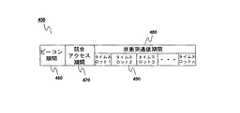
図4Bは、従来の動作方法に従って非衝突通信期間(Contention Free Period)に複数のタイムスロットを有する一連のスーパーフレームの構造例を示している。図4Aに示すように、このデータ送信方法においては、時間的に連続するスーパーフレーム450をネットワーク300を通して送信する。各スーパーフレーム450は、ビーコン460、任意選択の競合アクセス期間(Contention Access Period:CAP)470、及び非衝突通信期間(CFP)480を含む。非衝突通信期間480は一つ以上のタイムスロット490を含む。これらのスロットは、ネットワーク動作の観点から望ましい保証タイムスロット(Guaranteed Time Slots:GTSs)、管理タイムスロット(Management Time Slots:MTSs)または他のタイプのタイムスロットとすることができる。 FIG. 4B shows a structure example of a series of superframes having a plurality of time slots in a contention free period according to a conventional operation method. As shown in FIG. 4A, in this data transmission method, temporally
スーパーフレーム450は、それ自体、時間的に繰り返される固定時間の構成である。スーパーフレーム450の特定期間はビーコン460に記述される。実際、ビーコン460はどの位の頻度でビーコン460が繰り返されるかについての情報を含み、この頻度はスーパーフレーム450の期間に実質的に対応する。ビーコン460は、ネットワーク300に関する情報及び制御装置310の識別情報も含む。
動作状態において、制御装置310は、ビーコン460を使用してタイムスロット490を定義し、そして割り当てる。全てのデバイス321〜325は、ビーコン期間460の間、制御装置310からの電波を受信する。各デバイス321〜325は、ゼロまたは一つ以上のタイムスロット490を受信し、ビーコン期間460の間に制御装置310から各スタート時間及び各期間が通知される。このビーコン情報には、TLVフォーマットとよく呼ばれるもの、すなわちタイプ、長さ、及び値を表すものを使用する。その結果、各デバイスは、送信すべき時間及び受信すべき時間を知ることができる。従って、ビーコン期間460を使用して、デバイス321〜325の送信動作及び受信動作が調整される。 In the operating state, the
制御装置310は、各スーパーフレーム450の始めにビーコン460を全てのデバイス321〜325に送信する。ビーコン460により各デバイス321〜325は、期間またはスーパーフレーム450だけでなく、そのMACアドレスに関する他の情報、例えば競合アクセス期間470があるとすれば、そのサイズ及び期間、及び非衝突通信期間480の期間を知ることができる。 The
各ビーコン460は、正確にはチャネルタイムアロケーション(Channel Time Allocation:CTA)ではない情報を含む。一つの情報によりビーコン期間460が定義され、そしてビーコン期間460のスタート時間及び期間が記述される。別の情報により競合アクセス期間470があるとすればそれを定義し、そして競合アクセス期間470のスタート時間及び期間を記述する。各ビーコンは複数のCTAも含むことができる。タイムスロット490の各々に対応してCTAが在ることになる。動的タイムスロット490を使用して、スロット割当てをスーパーフレーム毎に変更CTAに従って変えることができる。 Each
ネットワークは、制御装置310と種々のデバイス321〜325との間で制御及び管理情報を競合アクセス期間470を通して、または管理タイムスロットの間に授受することができる。例えば、この情報はネットワーク300に参加しようとする新規デバイスについての情報を含むことができる。 The network may pass control and management information between the
新規デバイス321〜325がネットワーク300への参加を希望する場合、新規デバイスは競合アクセス期間470において、または接続管理タイムスロットの間に、制御装置310に対して参加許可をリクエストする。 If the new device 321-325 wants to join the
次に個々のデバイスは、非衝突通信期間480にデータパケットを送信する。デバイス321〜325は、それらに割り当てられたタイムスロット490を使用してデータパケットを他のデバイス(制御装置310がネットワーク300内の一つのデバイス321〜325でもある場合に制御装置310を含む)に送信する。各デバイス321〜325は、一つ以上のデータパケットを送信し、そして受信側デバイス321〜325からパケットが確実に届いたことを示すアクノリッジメント(ACK)フレームが即時に送信されるようにリクエストする、または、遅延(一括してまとめた)アクノリッジメントが送信されるようにリクエストすることができる。即時にACKフレームを送信するようにとのリクエストがある場合、送信側デバイス321〜325は、タイムスロット490に十分な時間を割り当ててACKフレームが届くようにする必要がある。 Each device then transmits a data packet during the
どのデバイス321〜325が送信を行なおうとしており、そして送信データの衝突を回避するためにどのデバイスが受信を行なうのかを調整する必要がある。例えば、デバイス1の321とデバイス4の324がともに同時にデータを送信しようとしているとすると、このデータは衝突するので受信側デバイスは信号を捕獲、受信する動作が行なえない。 It is necessary to adjust which
スーパーフレーム450に個々のタイムスロット490を割り当てるのは、所定のデバイス、例えばデバイス1の321が別のデバイス、例えばデバイス5の325に向けて送信を行なおうとしているときに、デバイス1は実際はその信号を全デバイスにブロードキャストする、すなわちたまたまそこに居合わせて受信を行なっている全デバイスが受信可能な場所でのオープンエア型のブロードキャストを行なうことになる。デバイス1の321が送信を行なっていた間にデバイス5の325が受信可能な唯一のデバイスであった状況が好ましい。これが基本的なTDMA手法である。ブロードキャスト媒体が無線であるので、一つのデバイスが送信を行なっているときにシステムは一体他のどのデバイスがチャネルを使用できるのかについて制限する必要がある。 Assigning
各特定のデバイス321〜325は、その送信開始時間及び送信期間をビーコン期間460の間に受信する情報から知ることができるので、各デバイス321〜325はその送信の順番が来るまで何もしない状態を維持することができる。 Since each
この本実施例に示すタイムスロット490は、異なるサイズとすることができる。タイムスロット490のスタート時間及び期間は、制御装置310により決定され、そしてビーコン460に記述されたデバイス321〜325に送信される。 The
現在のネットワーキング接続形態を使用して、各ネットワークのデバイスは同じネットワーク内の他のデバイスとのみ無線で通信を行なう。一つの無線ネットワークの第1デバイスが別の無線ネットワークの第2デバイスと通信するには、第1デバイスはイーサネット(Ethernet)、HomePNAまたはHomePLUGのような有線基幹回線を使用して接続を行なう必要がある。 Using current networking topologies, each network device communicates wirelessly only with other devices in the same network. In order for a first device in one wireless network to communicate with a second device in another wireless network, the first device needs to connect using a wired trunk line such as Ethernet, HomePNA or HomePLUG. is there.
この種のシステムにおいては、各無線ネットワークは一つのセルを形成し、そして個々のセルは有線基幹回線を通して接続される。IEEE 802.11システム及びHomeRFはこの種の有線インフラストラクチャ接続形態に依存する。 In this type of system, each wireless network forms one cell and the individual cells are connected through a wired backbone. The IEEE 802.11 system and HomeRF depend on this type of wired infrastructure topology.
またこのようなネットワーキング手法においては、アドホック・ネットワーキングはほとんどサポートされていない。そしてアドホック・ネットワーキングがサポートされている場合には、それは通常、他のアドホック・ネットワークに接続できない単一ピコネットに限定される。 In such networking techniques, ad hoc networking is hardly supported. And if ad hoc networking is supported, it is usually limited to a single piconet that cannot connect to other ad hoc networks.
インフラストラクチャをベースとする手法の別の不具合は、その手法が、ネットワークを互いにリンクさせるために有線基幹回線に依存することである。どのような所与の状況においても、この有線基幹回線を利用できるという保証は無い。また、現在ホーム環境に使用される有線基幹回線のほとんどはマルチメディア用途に対応するために必要とされるサービス要件であるスピードまたは品質をサポートしていない。 Another drawback of infrastructure-based approaches is that they rely on wired trunk lines to link networks together. There is no guarantee that this wired backbone can be used in any given situation. Also, most of the wired trunk lines currently used in home environments do not support speed or quality, which is a service requirement required to support multimedia applications.
従って、ネットワークが隣接ネットワークと固定有線基幹回線を使用する必要を生じることなく通信することができる手法を提供できれば、大きな利点となるであろう。 Thus, it would be a great advantage if the network could provide a technique that could communicate with adjacent networks without having to use a fixed wired backbone.
この節のタイトルに一致する形で、本発明から選択した特徴に関して以下に簡単に記載する。本発明をより完全に記載することが本文書全体の主題である。
本発明の特徴は、自己展開及び自律構成機能付きの「スマートな」マルチネットワークシステムを提供することにある。A brief description of features selected from the present invention in a manner consistent with the title of this section is provided below. A more complete description of the invention is the subject of this entire document.
A feature of the present invention is to provide a “smart” multi-network system with self-deployment and autonomous configuration functions.
本発明の別の特徴は、複数のオーバーラップする、または隣接する無線ネットワークの間の無線リンクを見つけ出し、そして更新する方法を提供することにある。
本発明の別の特徴は、異なる無線ネットワークに接続されるデバイスの間の通信を有線接続を必要とすることなく行なう方法を提供することにある。Another feature of the present invention is to provide a method for finding and updating wireless links between multiple overlapping or adjacent wireless networks.
Another feature of the present invention is to provide a method for communicating between devices connected to different wireless networks without requiring a wired connection.
これらの目的のうちの幾つかは、複数の無線ネットワークの間の無線リンクを見つけ出し、更新し、そして通信パスをマルチホップ・アドホック・ネットワークに確立することにより達成することができる。 Some of these objectives can be achieved by finding and updating wireless links between multiple wireless networks and establishing a communication path in a multi-hop ad hoc network.
これらの目的及び他の目的に従って、超高帯域無線スカッタネットが提供される。このスカッタネットは、第1ネットワーク及び第2ネットワークを備え、第1ネットワークは、第1ネットワークの動作を制御する第1制御装置であって、第1制御装置が確実に通信することができる最も遠い距離を表わす第1の利用可能な物理領域を有する第1制御装置と、第1の利用可能な物理領域に位置する一つ以上の第1デバイスとを含み、第2ネットワークは、第2ネットワークの動作を制御する第2制御装置であって、第2制御装置が確実に通信することができる最も遠い距離を表わす第2の利用可能な物理領域を有する第2制御装置と、第2の利用可能な物理領域に位置する一つ以上の第2デバイスとを含む。第1制御装置は第2の利用可能な物理領域内に在り、かつ第2制御装置は第1の利用可能な物理領域内に在る。このシステムにおいては、第1及び第2制御装置はネットワーク情報データを超高帯域信号を通して授受する。 In accordance with these and other objectives, an ultra high bandwidth wireless scatternet is provided. This scatter network includes a first network and a second network, and the first network is a first control device that controls the operation of the first network, and the first control device can communicate reliably. A first controller having a first available physical area representing a far distance and one or more first devices located in the first available physical area, wherein the second network is a second network A second control device for controlling the operation of the second control device, the second control device having a second available physical area representing the farthest distance with which the second control device can reliably communicate; And one or more second devices located in a possible physical area. The first controller is in the second available physical area and the second controller is in the first available physical area. In this system, the first and second control devices transmit and receive network information data through ultra-high bandwidth signals.
ネットワーク情報データは、ルータ/制御装置識別子、ネットワーク情報データのage指示子、ネットワーク情報データが制御装置間またはデバイス間で授受された回数のカウント、シーケンス番号、負荷フィードバック、接続ネットワークデバイスの数、近傍のメディアアクセス制御装置(Media Access Controller)のアドレスのリスト、サポートされるデータレートのリスト、利用可能なネットワークブリッジ接続のリスト、及び利用可能なネットワークサービスのリスト、のうちの少なくとも一つを含むことが好ましい。 Network information data includes router / control device identifier, network information data age indicator, count of the number of times network information data has been exchanged between control devices or devices, sequence number, load feedback, number of connected network devices, proximity Including at least one of: a media access controller address list, a supported data rate list, an available network bridge connection list, and an available network service list. Is preferred.
ネットワーク情報データは、第1及び第2制御装置がそれぞれ送信する第1及び第2超高帯域ビーコンを通して授受することができる。別の構成として、ネットワーク情報データは、第1及び第2制御装置がそれぞれ送信する第1及び第2超高帯域ブロードキャストメッセージを通して授受することができる。 The network information data can be exchanged through first and second ultra-high bandwidth beacons transmitted by the first and second control devices, respectively. Alternatively, the network information data can be exchanged through first and second ultra high bandwidth broadcast messages transmitted by the first and second control devices, respectively.
以下の構成の超高帯域無線スカッタネットも提供される。すなわち、このスカッタネットは、第1ネットワーク及び第2ネットワークを備え、第1ネットワークは、第1ネットワークの動作を制御する第1制御装置であって、第1制御装置が確実に通信することができる最も遠い距離を表わす第1の利用可能な物理領域を有する第1制御装置と、第1の利用可能な物理領域に位置する一つ以上の第1デバイスとを含み、第2ネットワークは、第2ネットワークの動作を制御する第2制御装置であって、第2制御装置が確実に通信することができる最も遠い距離を表わす第2の利用可能な物理領域を有する第2制御装置と、第2の利用可能な物理領域に位置する一つ以上の第2デバイスとを含む。一つ以上の第1制御装置のうちの少なくとも一つが第2の利用可能な物理領域内に在り、かつ中継デバイスとして動作する。このシステムにおいては、第1及び第2制御装置はネットワーク情報データを、中継デバイスを経由する超高帯域信号を通して授受する。 An ultra-high bandwidth wireless scatter network having the following configuration is also provided. That is, the scatter network includes a first network and a second network, and the first network is a first control device that controls the operation of the first network, and the first control device can reliably communicate. A first controller having a first available physical area representing the farthest possible distance and one or more first devices located in the first available physical area, the second network comprising: A second controller for controlling the operation of the two networks, the second controller having a second available physical area representing the farthest distance with which the second controller can reliably communicate; And one or more second devices located in an available physical area. At least one of the one or more first control devices is in the second available physical area and operates as a relay device. In this system, the first and second control devices send and receive network information data through ultra-high bandwidth signals that pass through the relay device.
別の超高帯域無線スカッタネットが提供され、このスカッタネットは、第1ネットワーク及び第2ネットワークを備え、第1ネットワークは、第1ネットワークの動作を制御する第1制御装置であって、第1制御装置が確実に通信することができる最も遠い距離を表わす第1の利用可能な物理領域を有する第1制御装置と、第1の利用可能な物理領域に位置する一つ以上の第1デバイスとを含み、第2ネットワークは、第2ネットワークの動作を制御する第2制御装置であって、第2制御装置が確実に通信することができる最も遠い距離を表わす第2の利用可能な物理領域を有する第2制御装置と、第2の利用可能な物理領域に位置する一つ以上の第2デバイスとを含む。一つ以上の第1デバイスのうちの一つは制御装置と成り得るデバイスであり、この制御装置と成り得るデバイスは子ネットワーク制御装置として動作して子ネットワークの動作を制御し、子ネットワーク制御装置は、子ネットワーク制御装置が確実に通信することができる最も遠い距離を表わす子ネットワーク利用可能な物理領域を有する。一つ以上の第2デバイスのうちの少なくとも一つは子ネットワーク利用可能な物理領域内に在り、かつ子ネットワークの子デバイスとして動作する。このシステムにおいては、第1及び第2制御装置はネットワーク情報データを、子ネットワークの子制御装置及び子デバイスを通して授受する。 Another ultra-high bandwidth wireless scatter network is provided, the scatter network comprising a first network and a second network, the first network being a first controller for controlling the operation of the first network, A first controller having a first available physical area representing the farthest distance with which the first controller can reliably communicate, and one or more first located in the first available physical area And the second network is a second controller that controls the operation of the second network, the second available physical representing the farthest distance that the second controller can reliably communicate with A second controller having a region, and one or more second devices located in a second available physical region. One of the one or more first devices is a device that can be a control device, and the device that can be the control device operates as a child network control device to control the operation of the child network. Has a physical area available to the child network that represents the farthest distance that the child network controller can reliably communicate with. At least one of the one or more second devices is in a physical area available for the child network and operates as a child device of the child network. In this system, the first and second control devices exchange network information data through the child control device and the child device of the child network.
超高帯域スカッタネットの第1及び第2超高帯域ネットワーク間でネットワーク情報データを共有する方法が提供される。この方法においては、第1ネットワークの第1制御装置から第1ネットワーク情報データを含む第1ビーコンを送信し、第1ビーコンを第2ネットワークの第2制御装置で受信し、そして第1ネットワーク情報データを第1ビーコンから第2制御装置で抽出する。 A method is provided for sharing network information data between first and second ultra high bandwidth networks of an ultra high bandwidth scatter network. In this method, a first beacon including first network information data is transmitted from a first control device of a first network, the first beacon is received by a second control device of a second network, and the first network information data Is extracted from the first beacon by the second control device.
またこの方法においては、第1ビーコンを第1制御装置から第2制御装置に第1制御装置及び第2制御装置両方の利用可能な物理領域の内に位置する中継デバイスを通して中継し、第1ビーコンを中継する操作は、第1ビーコンを送信するステップと第1ビーコンを受信するステップとの間に行なわれる。 In this method, the first beacon is relayed from the first control device to the second control device through a relay device located in an available physical area of both the first control device and the second control device. The operation of relaying is performed between the step of transmitting the first beacon and the step of receiving the first beacon.
中継デバイスは第1ネットワークの構成メンバー、または第2ネットワークの構成メンバーのいずれかであることが好ましい。
さらにこの方法においては、第2ネットワーク情報データを含む第2ビーコンを第2制御装置から送信し、第2ビーコンを第1制御装置で受信し、そして第2ネットワーク情報データを第2ビーコンから第1制御装置で抽出する。The relay device is preferably either a member of the first network or a member of the second network.
Further, in this method, a second beacon including second network information data is transmitted from the second control device, the second beacon is received by the first control device, and the second network information data is transmitted from the second beacon to the first. Extract by the control unit.
さらにこの方法においては、第2ビーコンを第2制御装置から第1制御装置に、第1制御装置の利用可能な物理領域及び第2制御装置の利用可能な物理領域の内に位置する中継デバイスを通して中継し、第2ビーコンを中継する操作は、第2ビーコンを送信するステップと第2ビーコンを受信するステップとの間に行なわれる。 Further, in this method, the second beacon is passed from the second control device to the first control device through the physical area available for the first control device and the relay device located within the available physical area for the second control device. The operation of relaying and relaying the second beacon is performed between the step of transmitting the second beacon and the step of receiving the second beacon.
中継デバイスは第1ネットワークの構成メンバー、または第2ネットワークの構成メンバーのいずれかであることが好ましい。
さらにこの方法においては、第1ビーコンを第1制御装置から第2制御装置に、第1制御装置の利用可能な物理領域及び第2制御装置の利用可能な物理領域の内に位置する中継デバイスを通して中継し、第1ビーコンを中継する操作は、第1ビーコンを送信するステップと第1ビーコンを受信するステップとの間に行なわれ、そして第2ビーコンを第2制御装置から第1制御装置に中継デバイスを通して中継し、第2ビーコンを中継する操作は、第2ビーコンを送信するステップと第2ビーコンを受信するステップとの間に行なわれる。The relay device is preferably either a member of the first network or a member of the second network.
Further, in this method, the first beacon is passed from the first control device to the second control device through a relay device located within the physical area available for the first control device and the physical area available for the second control device. The operation of relaying and relaying the first beacon is performed between the step of transmitting the first beacon and the step of receiving the first beacon, and relays the second beacon from the second controller to the first controller. The operation of relaying through the device and relaying the second beacon is performed between the step of transmitting the second beacon and the step of receiving the second beacon.
第2ネットワーク情報データは好ましくは、バージョン識別子、ブロードキャストメッセージタイプ、ルータ/制御装置識別子、ネットワーク情報データのage指示子、ネットワーク情報データが制御装置間またはデバイス間で授受された回数のカウント、シーケンス番号、負荷フィードバック、接続ネットワークデバイスの数、近傍のメディアアクセス制御装置(Media Access Controller)のアドレス、データレート、利用可能なネットワークブリッジ接続のリスト、及び利用可能なネットワークサービスのリスト、のうちの少なくとも一つを含むことが好ましい。 The second network information data is preferably a version identifier, a broadcast message type, a router / control device identifier, an age indicator of network information data, a count of the number of times the network information data has been exchanged between control devices or devices, a sequence number , Load feedback, number of connected network devices, address of neighboring media access controller (Media Access Controller), data rate, list of available network bridge connections, and list of available network services. Preferably including one.
第1ネットワーク情報データは好ましくは、バージョン識別子、ブロードキャストメッセージタイプ、ルータ/制御装置識別子、第1ネットワーク情報データのage指示子、第1ネットワーク情報データが制御装置間またはデバイス間で授受された回数のカウント、シーケンス番号、負荷フィードバック、接続ネットワークデバイスの数、近傍のメディアアクセス制御装置(Media Access Controller)のアドレス、データレート、利用可能なネットワークブリッジ接続のリスト、及び利用可能なネットワークサービスのリスト、のうちの少なくとも一つを含むことが好ましい。 The first network information data is preferably a version identifier, a broadcast message type, a router / control device identifier, an age indicator of the first network information data, and the number of times the first network information data has been exchanged between the control devices or devices. Of count, sequence number, load feedback, number of connected network devices, address of nearby media access controller (Media Access Controller), data rate, list of available network bridge connections, and list of available network services It is preferable to include at least one of them.
本発明の実施形態はスカッタネット接続形態を提供するものであり、この接続形態によりスカッタネット環境における種々のデバイス間の無線通信が可能になる。動作状態において、スカッタネット環境のデバイスは無線で互いにトラフィックを授受する。これに比べて、従来のネットワーキング手法では2つの異なるネットワークのデバイスは有線接続(すなわちブリッジング)を通してしか通信を行なうことができない。 Embodiments of the present invention provide a scatternet topology, which enables wireless communication between various devices in a scatternet environment. In the operational state, devices in a scatternet environment communicate with each other wirelessly. In contrast, conventional networking approaches allow two different network devices to communicate only through a wired connection (ie, bridging).
スカッタネットは、複数の無線ネットワークからなるシステムとして定義され、これらの無線ネットワークは一つ以上の無線リンクにより互いに接続される(ホップと呼ぶ)。ネットワーキングシステムは、各デバイスがスカッタネットを形成するネットワークのうちの一つとのリンクを有する限りにおいて、これらの異なるモバイルデバイスグループ間のリンクを見つけ出し、そして全てのユーザが他のどのようなユーザとも通信できるようにこれらのパスを確立させ、更新するように機能する。複数のモバイルデバイスからなるこの自律システムは他から絶縁された形で動作を行なう、または固定、すなわち有線ネットワークとの接続を行なうゲートウェイを有することができる。 A scatter network is defined as a system composed of a plurality of wireless networks, and these wireless networks are connected to each other by one or more wireless links (called hops). The networking system finds links between these different mobile device groups as long as each device has a link with one of the networks that form the scatternet, and all users are in contact with any other user. It functions to establish and update these paths so that they can communicate. This autonomous system consisting of a plurality of mobile devices can have a gateway that operates in an isolated manner from the other or that is fixed, ie connected to a wired network.
図5は本発明の好適な実施形態によるスカッタネットのブロック図である。スカッタネット500は3つの別個のオーバーラップするネットワーク、すなわちネットワークA 505a,ネットワークB 505b,及びネットワークC 505cを含む。基本的な機能において、これらのネットワーク505a,505b及び505cの構成要素は、図3に示す該当する構成要素と同じように動作する。ネットワーク505a,505b及び505cは図3に関連して上に記載したように、ピコネットまたは他の無線ネットワークとすることができる。 FIG. 5 is a block diagram of a scatternet according to a preferred embodiment of the present invention.
図5に示すように、ネットワークA 505aは制御装置510a及び複数のデバイス521a〜524aを、ネットワークB 505bは制御装置510b及び複数のデバイス521b〜522bを、そしてネットワークC 505cは制御装置510c及び複数のデバイス521c〜523cを含む。各デバイス521a〜524a,521b〜522b,521c〜523cはそのそれぞれの制御装置510a,510b,510cにプライマリー無線リンク530を通して接続される。また図示はしないが、各デバイス521a〜524a,521b〜522b,521c〜523cはそのネットワーク505a,505b,505c内の一つ以上の他のデバイス521a〜524a,521b〜522b,521c〜523cに、図3に関連して上に記載したようにセカンダリー無線リンクを通して接続される。 As shown in FIG. 5, a
所定のネットワークの種々のデバイス521a〜524a,521b〜522b,521c〜523cは、利用可能な物理領域550a,550b,550cに閉じ込められ、これらの物理領域は制御装置510a,510b,510cが、デバイス521a〜524a,521b〜522b,521c〜523cの各々と確実に通信できる度合いに基づいて設定される。所定の制御装置510a,510b,510cと通信可能なデバイス521a〜524a,521b〜522b,521c〜523c(及びその逆の場合も同じ)の全ては、ネットワーク505a,505b,505cの利用可能な領域550a,550b,550cの内に在る。しかしながら上述したように、所定のネットワーク505a,505b,505cのデバイス521a〜524a,521b〜522b,521c〜523cの全てが、そのネットワークの他の全てのデバイス521a〜524a,521b〜522b,521c〜523cと通信する必要はない。
3つのオーバーラップするネットワーク505a,505b及び505cが図5に示されるが、別の実施形態はこれより少ない、または多いネットワークを含むことができる。また図5の実施形態は、ネットワーク505a,505b及び505cの全てが利用可能な領域550a,550b,550cの内でオーバーラップする状態を示しているが、何らかの通信がネットワーク505a,505b,505cの構成要素間で可能であればこれらのネットワークはこの状態である必要はない。 Although three overlapping
またネットワークA 505aが4つのデバイス521a〜524aを、ネットワークB 505bが2つのデバイス521b〜522bを、ネットワークC 505cが3つのデバイス521c〜523cを有するように示されているが、別の実施形態では各ネットワークに含まれるデバイスの数を変えることができる。 Also,
図5を参照して上に記載したようなスカッタネット500においては、3つの異なるネットワーク505a,505b,505cの接続領域内に同時に位置するデバイス521a〜524a,521b〜522b,521c〜523cは、ネットワーク505a,505b,505c間の無線リンク/無線ブリッジの役割を果たすことになる。これらの特定のブリッジングデバイスは、無線ゲートウェイまたは無線プロキシノードと呼ばれる。 In the
図5において、デバイスA−4 524a及びデバイスC−1 521cは無線ゲートウェイとして機能することができる。デバイスA−4 524aはネットワークA 505a及びネットワークC 505cの利用可能な領域550a及び550cにそれぞれ位置する。同様に、デバイスC−1 521cはネットワークB 505b及びネットワークC 505cの利用可能な領域550b及び550cにそれぞれ位置する。 In FIG. 5,
デバイス521a〜524a,521b〜522b,521c〜523cの全てが無線ゲートウェイとして機能することができることが望ましいので、全てのデバイス521a〜524a,521b〜522b,521c〜523cが十分なバッファリング機能及び処理機能を有してワイヤレスブリッジングを処理することが好ましい。そして隣接するネットワーク505a,505b,505cは、送信側ネットワーク505a,505b,505cと同じチャネル周波数を使用することができないので、全てのデバイスは2つの異なるチャネル周波数間で切り替わる機能を備える必要がある。しかしながら別の実施形態では、ブリッジング機能は或る特定のデバイスに限定される。 Since it is desirable that all of the
上述のように、ネットワーク505a,505b,505cの制御装置510a,510b,510cは、システムを制御する追加機能及び制御装置がネットワーク505a,505b,505cのデバイス521a〜524a,521b〜522b,521c〜523cの全てと通信するという要件を除いて、デバイス521a〜524a,521b〜522b,521c〜523cのいずれかと同じ種類のデバイスとすることができる。 As described above, the
次に、制御装置化が可能なデバイス例及び制御装置化が不可能なデバイス例の動作について考察する。
起動時において、制御装置化可能なデバイスは、予め構成した一つ以上のチャネルを使用してランダムな期間に渡って受信することになる。受信期間の最後では、デバイスは、現ネットワークに通常デバイスとして参加する、現ネットワークの制御装置になろうと競合する、現ネットワークの子ネットワークを形成する、または全ての現在の隣接ネットワークとは異なるチャネルにより新規ネットワークを構築する、のいずれかを行なうことになる。Next, the operation of a device example that can be made into a control device and a device example that cannot be made into a control device will be considered.
At start-up, a device that can be made into a controller will receive for a random period using one or more pre-configured channels. At the end of the reception period, the device joins the current network as a normal device, competes to become the controller of the current network, forms a child network of the current network, or by a different channel than all current neighboring networks One of these is to build a new network.
制御装置化可能なデバイスが新規ネットワークを構築する場合、このデバイスは、隣接ネットワークとなり得るネットワークに重大な干渉を全く及ぼさないチャネル周波数を選択することが好ましい。信号干渉は、現在提案されているIEEE 802.15.3標準に示されるダイナミック送信電力制御アルゴリズムを使用することによりさらに減らすことができる。このアルゴリズムによりネットワークの利用可能な物理領域(すなわちセル領域)のサイズを調整して、ネットワーク間の接続を良好に維持しつつ空間の再利用を増やすことができる。 When a controller capable device builds a new network, it preferably selects a channel frequency that does not cause any significant interference to the network that can be a neighboring network. Signal interference can be further reduced by using the dynamic transmit power control algorithm shown in the currently proposed IEEE 802.15.3 standard. This algorithm can adjust the size of the available physical area (ie, cell area) of the network to increase the reuse of space while maintaining good connection between the networks.
初期化時に、制御装置化不可能なデバイスは、予め構成した一つ以上のチャネルを使用してランダムな期間に渡って受信することになる。受信期間の最後では、デバイスは、現ネットワークに通常デバイスとして参加する、またはデバイスが現ネットワークに参加できないことを示すエラーステートに入る(例えば、現ネットワークがない、帯域幅が十分ではない、など)、のいずれかを行なうことになる。 At initialization, a device that cannot be made into a controller will receive for a random period using one or more preconfigured channels. At the end of the reception period, the device joins the current network as a normal device, or enters an error state indicating that the device cannot join the current network (eg, no current network, insufficient bandwidth, etc.) , Either.
動作状態において、スカッタネット500の各制御装置510a,510b,510cは、周期的にビーコンをその利用可能な物理領域550a,550b,550c内のデバイスに送出する。好適には、これらのビーコン、またはそのビーコンの内容に関する他の全てのブロードキャストメッセージは、さらに、その接続ネットワーク505a,505b,505cに関するネットワーク情報を事あるごとに含むことになる。このネットワーク情報は、チャネル負荷、サービスクラス当りの利用可能な帯域幅、ネットワーク505a,505b,505cに接続される全てのデバイス521a〜524a,521b〜522b,521c〜523cのMACアドレステーブル、各デバイス521a〜524a,521b〜522b,521c〜523cの該当するデータレート/リンク品質、各デバイス521a〜524a,521b〜522b,521c〜523cが有する全ての最終的なブリッジ接続、そして各デバイス521a〜524a,521b〜522b,521c〜523cが提供するサービスタイプ(例えば、プリンティング、スキャニング、レコーディング、DVDプレーヤー、TVディスプレイ)、を含むことができる。このネットワーク情報は、関連データ転送仕様(例えば、IEEE 802.15.3仕様)に既に規定されている他の情報フィールドに加えられる。 In the operating state, each
ネットワーク505a,505b,505cに参加する前に、アクティブな送信要求を持たない非接続のデバイスは、まず、制御装置510a,510b,510cを選んで制御装置との接続を行なうことで、そのネットワーク505a,505b,505cを選択する前に複数のチャネル(すなわちビーコン)をスキャンする。このスキャンの判断は、例えば利用可能帯域幅、リンク品質またはバッテリー寿命のような基準に基づいて行なわれる。勿論、他の基準を用いることも可能である。 Before joining the
デバイスがその選択した制御装置510a,510b,510cとの接続を行なうとき、デバイスは、スキャニング段階で収集した隣接ネットワーク505a,505b,505cに関する幾つかの情報を制御装置510a,510b,510cに送信することが好ましい。この情報は、デバイスがネットワーク505a,505b,505cに参加するために制御装置510a,510b,510cが必要とする全ての情報に加えられる。 When a device makes a connection with its selected
隣接ネットワークに関するこの情報は、所定のネットワーク505a,505b,505cに固有の次の情報を含むことができる。すなわち、チャネル番号、チャネル負荷、送信電力、接続デバイス(すなわちノード)のテーブル、各デバイスから入手できるサービスのタイプ、さらにこれらに加えて、デバイスの受信範囲内の参加対象ネットワークと他の全てのネットワークとの間のオーバーラップ領域のタイプ、である。(図6A〜6C及び関連する説明を参照のこと)。 This information about neighboring networks can include the following information specific to a given
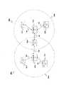
図6A〜6Cは、本発明の好適な実施形態による3つのタイプのネットワークオーバーラップを示している。図6Aは直接オーバーラップ(direct overlap)、図6Bは不可視オーバーラップ(hidden overlap)、6Cは間接オーバーラップ(indirect overlap)をそれぞれ示している。 6A-6C illustrate three types of network overlap according to a preferred embodiment of the present invention. FIG. 6A shows a direct overlap, FIG. 6B shows an invisible overlap, and 6C shows an indirect overlap.
図6Aは本発明の好適な実施形態による直接オーバーラップネットワークを示している。図6Aに示すように2つのネットワーク、ネットワークA 505a及びネットワークB 505bが部分的にオーバーラップする。ネットワークA 505aは、制御装置510a及び3つのデバイス521a〜523aを含む。ネットワークB 505bは、制御装置510b及び2つのデバイス521b〜522bを含む。これらの2つのネットワーク505a,505bは例示として示しているに過ぎない。別の実施形態においては、もっと多くのネットワークがオーバーラップし、そして各ネットワークが種々の数のデバイスを含むことができる。 FIG. 6A shows a direct overlap network according to a preferred embodiment of the present invention. As shown in FIG. 6A, the two networks,
直接オーバーラップ状況においては、制御装置510a,510bは、ともに他のネットワークの利用可能な物理領域550a,550b内に位置する。このようにして、各制御装置510a,510bは他のネットワーク505a,505bの存在及び設定を、他のネットワーク505a,505bの制御装置510a,510bが供給するビーコンを直接相互接続ネットワーク無線リンク570を通してモニターすることにより認識することができる。 In a direct overlap situation, the
この方法に代えて、制御装置510a,510bは、その保証タイムスロットのうちの一つを使用して一つのチャネルから別のチャネルに切り替わることにより、その固有のネットワークを妨害することなく他の制御装置と通信することができる。 As an alternative to this method, the
しかしながら、この直接接続に加えて、他のネットワーク505a,505bの利用可能な物理領域550a,550bに一つのデバイスを含んでいた直接オーバーラップ状況にあるネットワーク505a,505bのいずれも(これは本例の両方のネットワークに当てはまる)がそのデバイスをプロキシノードとして使用して、2つの異なるチャネルに位置する2つの制御装置間に仲介通信手段を形成することもできる。 However, in addition to this direct connection, any of the
図6Bは、本発明の好適な実施形態による不可視オーバーラップネットワークを示している。図6Bに示すように、2つのネットワーク、ネットワークA 505a及びネットワークB 505bが部分的にオーバーラップする。ネットワークA 505aは、制御装置510a及び3つのデバイス521a〜523aを含む。ネットワークB 505bは、制御装置510b及び2つのデバイス521b〜522bを含む。これらの2つのネットワーク505a,505bは、例示として示しているに過ぎない。別の実施形態においては、もっと多くのネットワークがオーバーラップし、そして各ネットワークが種々の数のデバイスを含むことができる。 FIG. 6B illustrates an invisible overlap network according to a preferred embodiment of the present invention. As shown in FIG. 6B, the two networks,
不可視オーバーラップ状況においては、制御装置510a,510bの両方が共に他のネットワーク505a,505bの利用可能な物理領域550a,550b内に位置するということではない。このように、制御装置510a,510bがともに他のネットワーク505a,505bの存在及び設定を直接認識できるという状況ではない。何故なら、制御装置は、他のネットワーク505a,505bの制御装置510a,510bが供給するビーコンを受信できないからである。利用可能な物理領域550a,550bがともに同じサイズである場合、これは均等条件と言える。しかしながら、仮に利用可能な物理領域550a及び550bが異なるサイズであるとすると、一つの制御装置510a,510bは他の制御装置510a,510bからの送信を受信することができるが、逆はそのようにはならない、という状況が生じ得る。制御装置510a,510bの両方が互いの送信を受信できるわけではないので、この状態も不可視オーバーラップ状況であると言える。 In an invisible overlap situation, both
しかしながら、不可視オーバーラップでは、少なくとも一つのネットワーク505a,505bが他のネットワーク505a,505bの利用可能な物理領域550a,550b内に一つのデバイスを含むことができる。これにより、このオーバーラップデバイスはプロキシノードとして機能し、そしてこの2つの制御装置510a,510bの間で間接相互接続ネットワーク無線リンク580を通してビーコンを渡す、またはメッセージ情報をブロードキャストすることができる。 However, with invisible overlap, at least one
ここで図6Bは、ネットワークA 505a及びネットワークB 505bの両方に一つのオーバーラップデバイスが含まれる形態を開示しているが、不可視オーバーラップ接続では、そのようなデバイスは一つのみで足りることに注目されたい。 Here, FIG. 6B discloses a form in which both the
図6Cは本発明の好適な実施形態による間接オーバーラップネットワークを示している。図6Cに示すように、2つの隣接ネットワーク(ネットワークA 505a及びネットワークB 505b)は、直接オーバーラップはしない。ネットワークA 505aは、制御装置510a及び3つのデバイス521a〜523aを含む。ネットワークB 505bは、制御装置510b及び2つのデバイス521b〜522bを含む。これらの2つのネットワーク505a,505bは、例示として示しているに過ぎない。別の実施形態においては、もっと多くのネットワークが互いに隣接して形成され、そして各ネットワークが種々の数のデバイスを含むことができる。 FIG. 6C illustrates an indirect overlap network according to a preferred embodiment of the present invention. As shown in FIG. 6C, the two adjacent networks (
間接オーバーラップ状況においては、2つのネットワーク505a及び505bの利用可能な物理領域550a及び550bは、いずれもオーバーラップしない。このように、制御装置510a,510bは、いずれも、他のネットワーク505a,505bの存在及び設定を他の制御装置510a,510bから直接、または他のネットワーク505a,505bの一つのデバイスを直接通して認識することができない。これは、各制御装置510a,510bが他のネットワーク505a,505bの構成要素のいずれとも通信できないからである。 In an indirect overlap situation, the available
しかしながら、間接オーバーラップの状況が生じる場合、ネットワーク505a,505bのうちの一つに含まれる少なくとも一つの制御装置化可能なデバイスは、子ネットワーク(すなわち、現ネットワーク内の一つのネットワーク)を形成して他の現ネットワーク505a,505bに含まれる少なくとも一つのデバイスがその子ネットワークの利用可能な物理領域560a,560b内に位置するように機能することができる。 However, if an indirect overlap situation occurs, at least one controllable device included in one of the
図6Cに示すように、ネットワークA 505aのデバイスA−2 522aは、制御装置化可能である(すなわち、このデバイスは制御装置と成り得る)。そして、デバイスA−2 522aが子ネットワークを形成すると、子ネットワークの利用可能な物理領域560aは、デバイスB−2 522bを包含するのに十分な大きさとなる。同じように、仮にネットワークB 505bのデバイスB−2 522bが制御装置化可能である(すなわち、制御装置と成り得る)とすると、このデバイスは、子ネットワークを形成することができ、そのネットワークの利用可能な物理領域560bは、デバイスA−2 522aを包含するのに十分な大きさとなる。どのデバイス522a,522bが子ネットワークを形成したのかに関係なく、2つのデバイス522a及び522bは、互いに子無線リンク590を通して通信する。 As shown in FIG. 6C,
図6Cは、デバイスA−2 522a及びデバイスB−2 522bの両方が制御装置化可能である状況を示しているが、これらのデバイスA−2 522a及びデバイスB−2 522bのうちの一つだけが制御装置化可能であれば十分である。いずれの場合でも、該当するデバイスが子ネットワークを形成し、そして通信ラインを開設することができる。 FIG. 6C shows a situation where both
図6Cに開示する間接オーバーラップ状況においては、デバイスA−2 522aは、ネットワークB 505bの存在及び設定について、デバイスB−2 522bが転送するそのビーコンメッセージをモニターすることにより認識する。次にデバイスA−2 522aは、この情報をネットワークA 505aの制御装置510aに転送する。同様にして、デバイスB−2 522bは、ネットワークA 505aの存在及び設定について、デバイスA−2 522aが転送するそのビーコンメッセージをモニターすることにより認識する。次にデバイスB−2 522bは、この情報をネットワークB 505bの制御装置510bに転送する。 In the indirect overlap situation disclosed in FIG. 6C,
このようにして一対のプロキシノードは、各ネットワーク505a,505bに含まれ、子ネットワークを形成する一つのデバイスによって形成される。次にこの子ネットワークは、2つのネットワーク505a及び505bとの間の無線ブリッジ機能を処理する。 In this way, a pair of proxy nodes is included in each of the
オーバーラップのタイプに関係なく、ネットワーク505a,505bの中で接続されている間、各デバイス521a〜523a,521b〜522bは、その制御装置510a,510bからの周期的な指示により他のチャネルをスキャンする必要があり、これによりもっと良好な制御装置、例えばより広い利用可能な帯域幅、より良好なQoS、より良好なリンク品質、またはより小さな送信電力を有する制御装置が利用可能かどうかを判断する。デバイスはまた、その制御装置510a,510bからの周期的な指示により隣接ネットワークを探し出し、そして可能であればこれらの隣接ネットワークのプロキシの役割を果たす必要がある。 Regardless of the type of overlap, while connected in the
この状況はデバイスに電力節減モードに入るように指示することにより実現する。別の構成として、時間的に余裕があれば、ネットワークはスーパーフレーム450の利用可能な非活性期間(すなわち、他のデバイス専用のタイムスロット490)を活用することができる。この操作は、複数のダイナミックGTSをタイムスロット490に使用すれば特に有効に作用する。何故なら、ネットワーク505a,505bの制御装置510a,510bは、その送信順序を再編成できるからである。デバイス521a〜523a,521b〜522bがその受信範囲内でより良好な制御装置510a,510bを探し出す場合、デバイスは、その制御装置510a,510bに移動する必要がある。 This situation is achieved by instructing the device to enter a power saving mode. Alternatively, if time permits, the network can take advantage of the available inactivity period of superframe 450 (ie, a
2つのネットワーク505a,505bの範囲内のデバイス521a〜523a,521b〜522bがプロキシノードになる決定を下す場合、デバイスは、2つの制御装置510a,510bのうちの一つにリクエストし、スーパーフレーム調整コマンドを送信することによりデバイスのスーパーフレームサイズ及びビーコン送信時間(TBTT)を動的に調整させる必要がある。 If the
図7は本発明の好適な実施形態によるスーパーフレーム調整コマンドを示している。図7に示すように、スーパーフレーム調整コマンド700はコマンドタイプフィールド710、長さフィールド720、スーパーフレーム期間フィールド730、及びビーコン送信時間(TBTT)フェーズフィールド740を含むことができる。 FIG. 7 illustrates a superframe adjustment command according to a preferred embodiment of the present invention. As shown in FIG. 7, the
スーパーフレーム調整コマンド700によりプロキシノードは、容易に一つのネットワーク505a,505bから別のネットワークに切り替わることができ、その間、2つの制御装置510a,510bが送信するビーコンメッセージを二者択一的に受信する機能を依然として保持することができる。 With the
幾つかのデバイスが同じ隣接無線ネットワークのプロキシの役割を果たすことが可能であるとすると、最大の中継器メモリサイズを有するデバイスが選択されることになる。
また、プロキシノードが複数のネットワーク505a,505bに同期する状態を維持するために、スカッタネット500内の各ネットワーク505a,505bは、同じ期間を有するスーパーフレーム450を使用しなければならないことになる(例えばデフォルト値に設定される)。Assuming that several devices can act as proxies for the same neighboring wireless network, the device with the largest repeater memory size will be selected.
In addition, in order to maintain a state in which the proxy node is synchronized with a plurality of
次に各制御装置510a,510bは、ブロードキャストメッセージを通常の周期(例えば毎秒または2秒毎に)で送信(ビーコン送信または他の送信)する役割を担うことになる。このブロードキャストメッセージは、メッセージに関連する全てのデバイスのリスト、その関連デバイスの各々が提供するサービスのタイプだけでなく、サポートされるデータレート、外部との利用可能な有線接続、及び必要に応じて他のフィールドのような幾つかの付加情報を含む必要がある。 Next, each
更新時間(すなわちブロードキャスト周期)は、デバイスの移動性の程度及び特定用途におけるネットワークの接続形態の変化速度に依存して変化することができる。低いデューティサイクルで送信される更新によりオーバーヘッドを最小化することができる。 The update time (ie, broadcast period) can vary depending on the degree of device mobility and the rate of change of the network topology in a particular application. Overhead can be minimized by updates sent at low duty cycles.
可視オーバーラップ状況(図6A参照)においては、制御装置510a及び510bはこの情報を直接渡すことになる。不可視オーバーラップ状況(図6B参照)においては、関連する制御装置510a,510bがこの情報をプロキシノードに渡し(無線ブリッジ)、このノードがブロードキャストメッセージを他の制御装置510a,510bに中継することになる。間接オーバーラップ状況(図6C参照)においては、関連する制御装置510a,510bは、この情報をその固有のネットワーク505a,505bの第1プロキシノードに渡すことになる。次に第1プロキシノードは、ブロードキャストメッセージを第2プロキシノードに中継することになるが、この第2プロキシノードは、第1プロキシノードの子ネットワーク、及び他の制御装置510a,510bが制御する他のネットワークの両方に位置する。次に第2プロキシノードは、ブロードキャストメッセージを他の制御装置510a,510bに中継することになる。 In a visible overlap situation (see FIG. 6A), the
オーバーラップのタイプに関係なく、一旦第2プロキシノードがブロードキャストメッセージを別のネットワークから(メッセージが通ることのできるルートを通して)受信すると、受信側制御装置510a,510bは、この情報をそれぞれそのデバイス521a〜523a,521b〜522bに送信し、この操作によってこれらのデバイスのネットワーク近傍リストが更新されることになる。その結果、各ネットワーク505a,505bの各デバイスは、全ての所定の時点で全スカッタネット500の全ネットワーク接続形態情報を有することになる。 Regardless of the type of overlap, once the second proxy node receives a broadcast message from another network (through the route that the message can pass), the receiving
図8は、本発明の好適な実施形態による近傍情報メッセージと呼ばれるブロードキャストメッセージのフォーマットを示している。このブロードキャストメッセージは、変形ビーコンメッセージまたは独立ブロードキャストメッセージとすることができる。図8に示すように、本発明の好適な実施形態によるブロードキャストメッセージは、MACヘッダフィールド805、シーケンス番号フィールド810、ルータ/制御装置識別子(ID)フィールド815、ageフィールド820、ホップカウントフィールド825、負荷フィードバックフィールド830、接続デバイス数フィールド835、及びデバイスレコードフィールド840を含む。デバイスレコードフィールド840は、一つ以上のデバイスレコード845を含む。各デバイスレコード845は、近傍MACアドレスフィールド850、ブリッジ接続フィールド855、サービスフィールド860、データレートフィールド865、及び必要に応じて幾つかの付加フィールド870を含む。(付加情報フィールド870は幾つかの実施形態では除かれる)。デバイスレコードフィールド840のデバイスレコード845の数は、ネットワークに含まれるデバイスの数に依存して変わる。 FIG. 8 shows a format of a broadcast message called a neighbor information message according to a preferred embodiment of the present invention. This broadcast message may be a modified beacon message or an independent broadcast message. As shown in FIG. 8, a broadcast message according to a preferred embodiment of the present invention includes a MAC header field 805, a sequence number field 810, a router / controller identifier (ID) field 815, an
シーケンス番号フィールド810は、より新しい近傍情報メッセージをより古い近傍情報メッセージから区別するために使用可能なシーケンス番号を含む。
ルータ/制御装置IDフィールド815は、その近傍テーブルをブロードキャストメッセージを通して送信している制御装置のMACアドレスを特定するルータ/制御装置IDを含む。The sequence number field 810 contains a sequence number that can be used to distinguish newer neighbor information messages from older neighbor information messages.
The router / control device ID field 815 includes a router / control device ID that identifies the MAC address of the control device that is transmitting the neighborhood table through a broadcast message.
ageフィールド820は、ブロードキャストメッセージが、それが廃棄されなければならなくなる前に有効である期間(例えば、1秒または2秒)を示す情報を含む。
ホップカウントフィールド825は、近傍情報メッセージがその送信元から幾つのホップを経由したかを示す情報を含む。このフィールドは、送信側制御装置/ルータが“0”に設定することが好ましい。各プロキシノードは、このフィールドを受信するとその値を1だけ増やすことになる。この好適な実施形態においては、近傍情報ブロードキャストメッセージは、ホップカウントフィールドが“2”よりも大きいホップ数を示す場合には転送されない。この制約はこのプロトコルが生じさせるオーバーヘッドを制限することになる。その結果、デバイスは0,1または2ホップだけ離れた近傍リストを表示するだけである。The
The
負荷フィードバックフィールド830は、接続デバイスがデータ転送に現時点で使用しているチャネル帯域幅量を時間単位で示す。これにより新規デバイスは、接続を試みる前に現在のチャネル負荷を見積もることができる。 The load feedback field 830 indicates the amount of channel bandwidth currently used for data transfer by the connected device in units of time. This allows the new device to estimate the current channel load before attempting a connection.
接続デバイス数フィールド835は、この特定の無線ネットワークの制御装置に直接接続されるデバイスの合計数を示す。
デバイスレコードフィールド840は、制御装置/ルータに直接接続される全てのデバイスだけでなく各デバイスに関連する幾つかの測定指標のリストを含む。近傍MACアドレスフィールド850は、その記入に関連するデバイスの近傍MACアドレスを含む。ブリッジ接続フィールド855は、その記入に関連するデバイスを通しての外部とのブリッジ接続の利用可能性についての情報を含む。サービスフィールド860は、その記入に関連するデバイス、例えばプリンタ、DVD,TVディスプレイなどが提供するサービスタイプについての情報を含む。データレートフィールド865は、その記入に関連するデバイスのリンクデータレートについての情報を含む。上述のように、他の情報870は、必要に応じてデバイスレコード845に含めることもできる。The number of
外部(例えばインターネット)との接続(すなわちブリッジ)を有するデバイス521a〜523a,521b〜522b,521c〜523cを公表することにより、システムは、デバイスがブリッジ接続の物理的位置から遠く離れている場合でも各デバイス521a〜523a,521b〜522b,521c〜523cが外部接続を行なえるメカニズムを提供することができる。 By announcing
各デバイス521a〜523a,521b〜522b,521c〜523cは、ネットワーク近傍可視化ツールも有していることが好ましく、このツールによりグラフィックインターフェイスを有するエンドユーザはユーザのスクリーン上に、無線ゲートウェイ/プロキシノードを通して直接または間接的に接続が行なわれる対象となる全てのデバイス521a〜523a,521b〜522b,521c〜523cだけでなく、これらのデバイス521a〜523a,521b〜522b,521c〜523cの各々が提供するサービス(例えば、プリンティング、スキャナー、DVDプレイヤー、TVディスプレイなど)も表示する。全ての操作はこの使い勝手の良いアプリケーション(例えばユニバーサルリモートコマンド)により実行することができる。 Each
このインターフェイスにより、エンドユーザが利用可能デバイスをウィンドウズベースのコンピュータのファイルを管理するのとほとんど同じやり方で管理することができるようになることが好ましい。このインターフェイスは、ユーザにネットワークネットワーク505a,505b,505cのリンクが現在どこに在るのかを通知することになり、そしてインターフェイスは5秒または10秒毎に更新されることが好ましい。 This interface preferably allows the end user to manage available devices in much the same way as managing files on a Windows-based computer. This interface will inform the user where the links of the
新規リンクの報告またはデッドリンクの消去を決定する前に安定性をさらに保証するために、ネットワーク近傍可視化ツールの更新周期はリンク発見ブロードキャストメッセージに対する周期よりも相当長く(例えば、1秒または2秒に対して5秒または10秒)する。 To further ensure stability before deciding to report a new link or eliminate a dead link, the network neighborhood visualization tool update period is much longer than the period for link discovery broadcast messages (eg, 1 or 2 seconds). (5 seconds or 10 seconds).
大きな展開が見込まれる複数ネットワーク構成のスカッタネットの複雑さを減らすためには、スカッタネットのデバイスマップの解像度は制限されることになる。ネットワーキング近傍可視化ツールは、デバイスから1ホップまたは2ホップだけ離れた近傍デバイス及びサービスのみを表示することが好ましい。しかしながら別の実施形態においては、この制約を変更してホップ数を増やして、または減らして、或いは無くしてしまうことができる。 In order to reduce the complexity of a multi-network scatternet that is expected to expand significantly, the resolution of the scatternet device map will be limited. The networking proximity visualization tool preferably displays only neighboring devices and services that are one or two hops away from the device. However, in other embodiments, this constraint can be changed to increase, decrease, or eliminate the number of hops.
明らかなことであるが、本発明の変形及び変更は上述の示唆を参照すれば可能である。例えば、記載された例は全て超高帯域ネットワークの例であるが、上に開示したシステム及び方法は等価な条件で他の無線ネットワークに適用可能である。従って、添付の請求項の技術範囲内で、本発明を本明細書に特定の形で記載した以外の方法で実施することが可能であることは理解されるべきものと考えられる。 Obviously, variations and modifications of the present invention are possible with reference to the above suggestions. For example, the examples described are all examples of ultra-high bandwidth networks, but the systems and methods disclosed above are applicable to other wireless networks under equivalent conditions. It is therefore to be understood that within the scope of the appended claims, the invention may be practiced otherwise than as specifically described herein.
Claims (4)
Translated fromJapanese第1ネットワークと第2ネットワークとを備え、
前記第1ネットワークは、
前記第1ネットワークの動作を制御する第1制御装置であって、前記第1制御装置が確実に通信することができる最も遠い距離を表わす第1の利用可能な物理領域を有する第1制御装置と、
前記第1の利用可能な物理領域に位置する第3デバイスであって、前記第3デバイスが確実に通信することができる最も遠い距離を表す第3の利用可能な物理領域を有する第3デバイスとを含み、
前記第2ネットワークは、
前記第2ネットワークの動作を制御する第2制御装置であって、前記第2制御装置が確実に通信することができる最も遠い距離を表わす第2の利用可能な物理領域を有する第2制御装置と、
前記第2の利用可能な物理領域に位置する第4デバイスであって、前記第4デバイスが確実に通信することができる最も遠い距離を表す第4の利用可能な物理領域を有する第4デバイスとを含み、
前記第1制御装置は前記第2の利用可能な物理領域内に無く、かつ前記第2制御装置は前記第1の利用可能な物理領域内に無く、
前記第3デバイスは、前記第4の利用可能な物理領域内に在り、かつ前記第4デバイスは前記第3の利用可能な物理領域内に在り、
前記第1及び第2制御装置は、ネットワーク情報データを前記第3及び第4デバイスを経由する超高帯域信号を通して授受するように構成され、
前記第1制御装置は、前記ネットワーク情報データに基づいて、前記第1の利用可能な物理領域に位置する複数のデバイスに、前記第1及び第2の利用可能な物理領域に位置する複数のデバイスとのネットワークパスの確立と更新を周期的に行なわせるように構成され、
前記第2制御装置は、前記ネットワーク情報データに基づいて、前記第2の利用可能な物理領域に位置する複数のデバイスに、前記第1及び第2の利用可能な物理領域に位置する複数のデバイスとのネットワークパスの確立と更新を周期的に行なわせるように構成されている、超高帯域無線スカッタネット。An ultra-high bandwidth wireless scatter network,
A first network and a second network;
The first network is:
A first control device for controlling the operation of the first network, the first control device having a first available physical area representing the farthest distance with which the first control device can reliably communicate; ,
A third device located in the first available physical area, the third device having a third available physical area representing the farthest distance with which the third device can reliably communicate; Including
The second network is
A second control device for controlling the operation of the second network, the second control device having a second available physical area representing the farthest distance with which the second control device can reliably communicate; ,
A fourth device located in the second available physical area, the fourth device having a fourth available physical area representing the farthest distance with which the fourth device can reliably communicate; Including
The first controller is not in the second available physical area, and the second controller is not in the first available physical area;
The third device is in the fourth available physical area, and the fourth device is in the third available physical area;
The first and second control devices areconfigured to send and receive network information data through ultra-high bandwidth signals passing through the third and fourth devices,
The first control device includes a plurality of devices located in the first and second available physical areas based on the network information data, and a plurality of devices located in the first and second available physical areas. Is configured to periodically establish and update the network path with
The second control device includes a plurality of devices located in the first and second available physical areas based on the network information data, and a plurality of devices located in the first and second available physical areas. network establishing and updating of the path thatis configured to periodically performed, ultra-high bandwidth wireless scan cutternet with.
前記第1ネットワークの第1制御装置から第1ネットワーク情報データを含む第1ビーコンを送信し、
前記第1ビーコンを前記第1ネットワークの前記第1制御装置から前記第2ネットワークの第2制御装置に第1及び第2中継デバイスを介して中継し、
前記第2ネットワークの第2制御装置で前記第1ビーコンを受信し、
前記第1ネットワーク情報データを前記第1ビーコンから前記第2制御装置で抽出することを備え、
前記第1制御装置は、前記第1中継デバイスの第3の利用可能な物理領域に位置し、前記第2制御装置の第2の利用可能な物理領域に位置せず、
前記第2制御装置は、前記第2中継デバイスの第4の利用可能な物理領域に位置し、前記第1制御装置の第1の利用可能な物理領域に位置せず、
前記第1中継デバイスは、前記第1制御装置の前記第1の利用可能な物理領域及び前記第2中継デバイスの前記第4の利用可能な物理領域に位置し、前記第2制御装置の前記第2の利用可能な物理領域に位置せず、
前記第2中継デバイスは、前記第2制御装置の前記第2の利用可能な物理領域及び前記第1中継デバイスの前記第3の利用可能な物理領域に位置し、前記第1制御装置の前記第1の利用可能な物理領域に位置せず、
前記第1制御装置は、前記第1ネットワーク情報データに基づいて、前記第1の利用可能な物理領域に位置する複数のデバイスに、前記第1及び第2の利用可能な物理領域に位置する複数のデバイスとのネットワークパスの確立と更新を周期的に行なわせるように構成され、
前記第2制御装置は、前記第1ネットワーク情報データに基づいて、前記第2の利用可能な物理領域に位置する複数のデバイスに、前記第1及び第2の利用可能な物理領域に位置する複数のデバイスとのネットワークパスの確立と更新を周期的に行なわせるように構成される、方法。A method of sharing network information data between first and second ultra-high bandwidth networks of an ultra-high bandwidth wireless scatter network,
Transmitting a first beacon including first network information data from a first control device of the first network;
Relays via the first and second relay device to a second controllerof the second networkthefirst beacon from the first controller of thefirst network,
Receiving the first beacon at a second control device of the second network;
Extracting the first network information data from the first beacon with the second control device;
The first controller is located in a third available physical area of the first relay device, not located in a second available physical area of the second controller;
The second controller is located in a fourth available physical area of the second relay device, not located in a first available physical area of the first controller;
The first relay device is located in the first available physical area of the first control device and the fourth available physical area of the second relay device, and the first relay device of the second control device Is not located in 2 available physical areas,
The second relay device is located in the second available physical area of the second control device and the third available physical area of the first relay device, and the second relay device is the first of the first control device.Not located in one available physical area,
A plurality of devices located in the first and second available physical areas based on the first network information data, the plurality of devices located in the first and second available physical areas; Configured to periodically establish and update network paths with other devices,
A plurality of devices located in the first and second available physical areas based on the first network information data; and a plurality of devices located in the first and second available physical areas. A methodconfigured to cause periodic establishment and update of a network path with a device .
第1ネットワークと第2ネットワークとを備え、
前記第1ネットワークは、
前記第1ネットワークの動作を制御する第1制御装置であって、前記第1制御装置が確実に通信することができる最も遠い距離を表わす第1の利用可能な物理領域を有する第1制御装置と、
前記第1の利用可能な物理領域に位置する一つ以上の第1デバイスとを含み、
前記第2ネットワークは、
前記第2ネットワークの動作を制御する第2制御装置であって、前記第2制御装置が確実に通信することができる最も遠い距離を表わす第2の利用可能な物理領域を有する第2制御装置と、
前記第2の利用可能な物理領域に位置する一つ以上の第2デバイスとを含み、
前記一つ以上の第1デバイスのうちの少なくとも一つが前記第2の利用可能な物理領域内に在り、かつ中継デバイスとして動作し、
前記第1及び第2制御装置は、ネットワーク情報データを、前記中継デバイスを経由する超高帯域信号を通して授受するように構成され、
前記第1制御装置は、前記ネットワーク情報データに基づいて、前記第1の利用可能な物理領域に位置する複数のデバイスに、前記第1及び第2の利用可能な物理領域に位置する複数のデバイスとのネットワークパスの確立と更新を周期的に行なわせるように構成され、
前記第2制御装置は、前記ネットワーク情報データに基づいて、前記第2の利用可能な物理領域に位置する複数のデバイスに、前記第1及び第2の利用可能な物理領域に位置する複数のデバイスとのネットワークパスの確立と更新を周期的に行なわせるように構成されている、超高帯域無線スカッタネット。An ultra-high bandwidth wireless scatter network,
A first network and a second network;
The first network is:
A first control device for controlling the operation of the first network, the first control device having a first available physical area representing the farthest distance with which the first control device can reliably communicate; ,
One or more first devices located in the first available physical area,
The second network is
A second control device for controlling the operation of the second network, the second control device having a second available physical area representing the farthest distance with which the second control device can reliably communicate; ,
One or more second devices located in the second available physical area,
At least one of the one or more first devices is in the second available physical area and operates as a relay device;
The first and second control devices areconfigured to send and receive network information data through ultra-high bandwidth signals passing through the relay device,
The first control device includes a plurality of devices located in the first and second available physical areas based on the network information data, and a plurality of devices located in the first and second available physical areas. Is configured to periodically establish and update the network path with
The second control device includes a plurality of devices located in the first and second available physical areas based on the network information data, and a plurality of devices located in the first and second available physical areas. network establishing and updating of the path thatis configured to periodically performed, ultra-high bandwidth wireless scan cutternet with.
第1ネットワークと第2ネットワークとを備え、
前記第1ネットワークは、
前記第1ネットワークの動作を制御する第1制御装置であって、前記第1制御装置が確実に通信することができる最も遠い距離を表わす第1の利用可能な物理領域を有する第1制御装置と、
前記第1の利用可能な物理領域に位置する一つ以上の第1デバイスとを含み、
前記第2ネットワークは、
前記第2ネットワークの動作を制御する第2制御装置であって、前記第2制御装置が確実に通信することができる最も遠い距離を表わす第2の利用可能な物理領域を有する第2制御装置と、
前記第2の利用可能な物理領域に位置する一つ以上の第2デバイスとを含み、
前記一つ以上の第1デバイスのうちの一つは制御装置と成り得るデバイスであり、
前記制御装置と成り得るデバイスは、子ネットワーク制御装置として動作して子ネットワークの動作を制御し、前記子ネットワーク制御装置は、前記子ネットワーク制御装置が確実に通信することができる最も遠い距離を表わす子ネットワーク利用可能な物理領域を有し、
前記一つ以上の第2デバイスのうちの少なくとも一つが前記子ネットワーク利用可能な物理領域内に在り、かつ前記子ネットワークの子デバイスとして動作し、
前記第1及び第2制御装置は、ネットワーク情報データを、前記子ネットワークの前記子制御装置及び前記子デバイスを通して授受するように構成され、
前記第1制御装置は、前記ネットワーク情報データに基づいて、前記第1の利用可能な物理領域に位置する複数のデバイスに、前記第1及び第2の利用可能な物理領域に位置する複数のデバイスとのネットワークパスの確立と更新を周期的に行なわせるように構成され、
前記第2制御装置は、前記ネットワーク情報データに基づいて、前記第2の利用可能な物理領域に位置する複数のデバイスに、前記第1及び第2の利用可能な物理領域に位置する複数のデバイスとのネットワークパスの確立と更新を周期的に行なわせるように構成されている、超高帯域無線スカッタネット。An ultra-high bandwidth wireless scatter network,
A first network and a second network;
The first network is:
A first control device for controlling the operation of the first network, the first control device having a first available physical area representing the farthest distance with which the first control device can reliably communicate; ,
One or more first devices located in the first available physical area,
The second network is
A second control device for controlling the operation of the second network, the second control device having a second available physical area representing the farthest distance with which the second control device can reliably communicate; ,
One or more second devices located in the second available physical area,
One of the one or more first devices is a device that can be a control device;
The device that can be the control device operates as a child network control device to control the operation of the child network, and the child network control device represents the farthest distance that the child network control device can reliably communicate with The child network has a physical area available,
At least one of the one or more second devices is in a physical area available to the child network and operates as a child device of the child network;
The first and second control devices areconfigured to exchange network information data through the child control device and the child device of the child network,
The first control device includes a plurality of devices located in the first and second available physical areas based on the network information data, and a plurality of devices located in the first and second available physical areas. Is configured to periodically establish and update the network path with
The second control device includes a plurality of devices located in the first and second available physical areas based on the network information data, and a plurality of devices located in the first and second available physical areas. network establishing and updating of the path thatis configured to periodically performed, ultra-high bandwidth wireless scan cutternet with.
Applications Claiming Priority (2)
| Application Number | Priority Date | Filing Date | Title |
|---|---|---|---|
| US33352401P | 2001-11-28 | 2001-11-28 | |
| PCT/US2002/037897WO2003047176A1 (en) | 2001-11-28 | 2002-11-27 | System and method of communication between multiple point-coordinated wireless networks |
Publications (2)
| Publication Number | Publication Date |
|---|---|
| JP2005537692A JP2005537692A (en) | 2005-12-08 |
| JP4383878B2true JP4383878B2 (en) | 2009-12-16 |
Family
ID=23303148
Family Applications (1)
| Application Number | Title | Priority Date | Filing Date |
|---|---|---|---|
| JP2003548471AExpired - Fee RelatedJP4383878B2 (en) | 2001-11-28 | 2002-11-27 | Communication system and communication method between wireless networks integrating a plurality of points |
Country Status (10)
| Country | Link |
|---|---|
| US (1) | US7184767B2 (en) |
| EP (1) | EP1461908B1 (en) |
| JP (1) | JP4383878B2 (en) |
| KR (1) | KR20040053383A (en) |
| CN (1) | CN100433673C (en) |
| AT (1) | ATE334531T1 (en) |
| AU (1) | AU2002359487A1 (en) |
| CA (1) | CA2468779A1 (en) |
| DE (1) | DE60213469T2 (en) |
| WO (1) | WO2003047176A1 (en) |
Families Citing this family (159)
| Publication number | Priority date | Publication date | Assignee | Title |
|---|---|---|---|---|
| US7095754B2 (en) | 2000-11-03 | 2006-08-22 | At&T Corp. | Tiered contention multiple access (TCMA): a method for priority-based shared channel access |
| US7136361B2 (en) | 2001-07-05 | 2006-11-14 | At&T Corp. | Hybrid coordination function (HCF) access through tiered contention and overlapped wireless cell mitigation |
| US7277413B2 (en) | 2001-07-05 | 2007-10-02 | At & T Corp. | Hybrid coordination function (HCF) access through tiered contention and overlapped wireless cell mitigation |
| US7277415B2 (en)* | 2001-11-02 | 2007-10-02 | At&T Corp. | Staggered startup for cyclic prioritized multiple access (CPMA) contention-free sessions |
| US7180905B2 (en)* | 2001-11-02 | 2007-02-20 | At & T Corp. | Access method for periodic contention-free sessions |
| US7280517B2 (en)* | 2001-11-02 | 2007-10-09 | At&T Corp. | Wireless LANs and neighborhood capture |
| US7245605B2 (en) | 2001-11-02 | 2007-07-17 | At&T Corp. | Preemptive packet for maintaining contiguity in cyclic prioritized multiple access (CPMA) contention-free sessions |
| US7245604B2 (en)* | 2001-11-02 | 2007-07-17 | At&T Corp. | Fixed deterministic post-backoff for cyclic prioritized multiple access (CPMA) contention-free sessions |
| US7248600B2 (en) | 2001-11-02 | 2007-07-24 | At&T Corp. | ‘Shield’: protecting high priority channel access attempts in overlapped wireless cells |
| US7181214B1 (en)* | 2001-11-13 | 2007-02-20 | Meshnetworks, Inc. | System and method for determining the measure of mobility of a subscriber device in an ad-hoc wireless network with fixed wireless routers and wide area network (WAN) access points |
| US8780770B2 (en) | 2002-05-13 | 2014-07-15 | Misonimo Chi Acquisition L.L.C. | Systems and methods for voice and video communication over a wireless network |
| US7941149B2 (en)* | 2002-05-13 | 2011-05-10 | Misonimo Chi Acquistion L.L.C. | Multi-hop ultra wide band wireless network communication |
| US7852796B2 (en) | 2002-05-13 | 2010-12-14 | Xudong Wang | Distributed multichannel wireless communication |
| US7957356B2 (en)* | 2002-05-13 | 2011-06-07 | Misomino Chi Acquisitions L.L.C. | Scalable media access control for multi-hop high bandwidth communications |
| FR2841716B1 (en)* | 2002-06-28 | 2005-02-04 | Thomson Licensing Sa | METHOD OF CREATING A NEW COMMUNICATION NETWORK BY A WIRELESS TERMINAL AND TERMINAL USING THE METHOD |
| US7007223B2 (en)* | 2002-06-30 | 2006-02-28 | Intel Corporation | Efficient method and apparatus for low latency forward error correction |
| US7508801B1 (en) | 2003-03-21 | 2009-03-24 | Cisco Systems, Inc. | Light-weight access point protocol |
| US7313113B1 (en) | 2003-04-04 | 2007-12-25 | Airespace, Inc. | Dynamic transmit power configuration system for wireless network environments |
| US7301926B1 (en) | 2003-04-04 | 2007-11-27 | Airespace, Inc. | Automatic coverage hole detection in computer network environments |
| US7388886B2 (en)* | 2003-04-16 | 2008-06-17 | Motorola, Inc. | Method and device for distributing communication signals |
| KR20060007009A (en)* | 2003-05-07 | 2006-01-23 | 소니 가부시끼 가이샤 | Wireless communication system, wireless communication device, wireless communication method and computer program |
| US20050128991A1 (en)* | 2003-05-08 | 2005-06-16 | Sriram Dayanandan | Coordination between simultaneously operating Pico-Nets in high mobility wireless networks |
| US7668124B2 (en)* | 2003-05-21 | 2010-02-23 | Broadcom Corporation | Position based WPAN (Wireless Personal Area Network) management |
| US7340247B1 (en)* | 2003-05-29 | 2008-03-04 | Airespace, Inc. | Wireless network infrastructure including wireless discovery and communication mechanism |
| US7539169B1 (en) | 2003-06-30 | 2009-05-26 | Cisco Systems, Inc. | Directed association mechanism in wireless network environments |
| US7532640B2 (en)* | 2003-07-02 | 2009-05-12 | Caterpillar Inc. | Systems and methods for performing protocol conversions in a machine |
| US7983820B2 (en)* | 2003-07-02 | 2011-07-19 | Caterpillar Inc. | Systems and methods for providing proxy control functions in a work machine |
| US7362724B2 (en)* | 2003-07-09 | 2008-04-22 | Motorola, Inc. | Method for rigid body discovery and peer-to-peer ranging in a scatternet and communications node |
| WO2005006658A1 (en)* | 2003-07-11 | 2005-01-20 | Nokia Corporation | Beacon transmission in short-range wireless communication systems |
| KR101195304B1 (en) | 2003-07-17 | 2012-10-26 | 인터디지탈 테크날러지 코포레이션 | Method and system for delivery of assistance data |
| US7319674B2 (en)* | 2003-07-24 | 2008-01-15 | Cisco Technology, Inc. | System and method for exchanging awareness information in a network environment |
| KR100547788B1 (en) | 2003-07-31 | 2006-01-31 | 삼성전자주식회사 | High speed personal wireless network and data transmission method capable of communication between devices of piconets |
| KR101025085B1 (en) | 2003-08-06 | 2011-03-25 | 파나소닉 주식회사 | Master station and access control method of communication system |
| US7324468B2 (en)* | 2003-09-10 | 2008-01-29 | Broadcom Corporation | System and method for medium access control in a power-save network |
| US8233462B2 (en) | 2003-10-15 | 2012-07-31 | Qualcomm Incorporated | High speed media access control and direct link protocol |
| US8472473B2 (en) | 2003-10-15 | 2013-06-25 | Qualcomm Incorporated | Wireless LAN protocol stack |
| US8462817B2 (en) | 2003-10-15 | 2013-06-11 | Qualcomm Incorporated | Method, apparatus, and system for multiplexing protocol data units |
| US8483105B2 (en) | 2003-10-15 | 2013-07-09 | Qualcomm Incorporated | High speed media access control |
| US9226308B2 (en) | 2003-10-15 | 2015-12-29 | Qualcomm Incorporated | Method, apparatus, and system for medium access control |
| US8010633B2 (en)* | 2003-10-20 | 2011-08-30 | Sony Computer Entertainment America Llc | Multiple peer-to-peer relay networks |
| KR100772855B1 (en)* | 2003-10-29 | 2007-11-02 | 삼성전자주식회사 | Method for Exchanging Data between Devices on Wireless Personal Area Network |
| JP2007510350A (en)* | 2003-10-29 | 2007-04-19 | サムスン エレクトロニクス カンパニー リミテッド | Method for efficiently transmitting and receiving data between devices over wireless PAN |
| US7515924B2 (en)* | 2003-10-30 | 2009-04-07 | Qualcomm Incorporated | Method and module for operating independently of a remote terminal if an incoming pilot signal is not detected within a time period and enabling a pilot signal transmission |
| DE10350906B4 (en)* | 2003-10-31 | 2005-12-01 | Siemens Ag | Method for determining a path in an ad hoc radio communication system |
| DE60312994T2 (en)* | 2003-11-06 | 2007-12-13 | Mitsubishi Denki K.K. | Method and device for managing a common transmission medium |
| JP2007521766A (en)* | 2003-11-07 | 2007-08-02 | シャープ株式会社 | Network coordination system and method using limited explicit message exchange |
| US8213301B2 (en) | 2003-11-07 | 2012-07-03 | Sharp Laboratories Of America, Inc. | Systems and methods for network channel characteristic measurement and network management |
| KR100640327B1 (en) | 2003-11-24 | 2006-10-30 | 삼성전자주식회사 | New Frame Structure and Data Transmission Method for Bridge Operation in High-Speed Personal Wireless Network |
| JP2005167460A (en) | 2003-12-01 | 2005-06-23 | Matsushita Electric Ind Co Ltd | Electronic device and wireless network system connectable to wireless network |
| KR100547849B1 (en)* | 2003-12-05 | 2006-01-31 | 삼성전자주식회사 | Frame Structure for Selecting Bridge Device in WPAN and Method for Selecting Bridge Device in WPAN |
| US8903440B2 (en) | 2004-01-29 | 2014-12-02 | Qualcomm Incorporated | Distributed hierarchical scheduling in an ad hoc network |
| KR100714675B1 (en)* | 2004-01-30 | 2007-05-07 | 삼성전자주식회사 | Data frame retransmission method and network device using the method |
| US7519371B2 (en)* | 2004-02-09 | 2009-04-14 | Qualcomm Incorporated | Multi-hop communications in a wireless network |
| US7346129B2 (en)* | 2004-02-25 | 2008-03-18 | Broadcom Corporation | Payload based channel estimation of a wireless channel |
| US20050210121A1 (en)* | 2004-03-22 | 2005-09-22 | Qualcomm Incorporated | Satellite anticipatory bandwith acceleration |
| US7937088B2 (en)* | 2004-03-26 | 2011-05-03 | Qualcomm Incorporated | Routing communications in an ad hoc network |
| US7978710B2 (en)* | 2004-03-26 | 2011-07-12 | Qualcomm Incorporated | Synchronous inter-piconet routing |
| US7907898B2 (en)* | 2004-03-26 | 2011-03-15 | Qualcomm Incorporated | Asynchronous inter-piconet routing |
| US7433696B2 (en) | 2004-05-18 | 2008-10-07 | Cisco Systems, Inc. | Wireless node location mechanism featuring definition of search region to optimize location computation |
| US8401018B2 (en) | 2004-06-02 | 2013-03-19 | Qualcomm Incorporated | Method and apparatus for scheduling in a wireless network |
| USRE46001E1 (en) | 2004-07-22 | 2016-05-10 | Koninklijke Philips N.V. | Method of connecting a new device to existing network |
| DE602005023736D1 (en)* | 2004-07-22 | 2010-11-04 | Philips Intellectual Property | PROCEDURE FOR CONNECTING A NEW DEVICE TO AN EXISTING NETWORK |
| US7506042B2 (en) | 2004-08-06 | 2009-03-17 | Sharp Laboratories Of America, Inc. | Hierarchical ad hoc network organizational method involving with proxy networking |
| DE102004040070B3 (en)* | 2004-08-18 | 2006-03-02 | Siemens Ag | Establishment of a wireless network under identification and use of local topology information |
| TWI375418B (en)* | 2004-10-20 | 2012-10-21 | Koninkl Philips Electronics Nv | A system and method for dynamic adaptation of data rate and transmit power with a beaconing protocol |
| US7516174B1 (en) | 2004-11-02 | 2009-04-07 | Cisco Systems, Inc. | Wireless network security mechanism including reverse network address translation |
| US7457262B1 (en) | 2004-11-05 | 2008-11-25 | Cisco Systems, Inc. | Graphical display of status information in a wireless network management system |
| DE102004055720A1 (en)* | 2004-11-18 | 2006-05-24 | Siemens Ag | Method for controlling a handover between network access devices |
| US7542730B2 (en) | 2004-11-24 | 2009-06-02 | Research In Motion Limited | Method and system for filtering wavetable information for wireless devices |
| KR100757260B1 (en)* | 2004-12-14 | 2007-09-11 | 전자부품연구원 | How to implement scatternet in a private wireless network |
| US20060133415A1 (en)* | 2004-12-21 | 2006-06-22 | Mueller Peter D | Wireless internetwork transfer apparatus, systems, and methods |
| CN101076977B (en)* | 2004-12-21 | 2011-01-05 | 松下电器产业株式会社 | Wireless node power supply managing method |
| US20060166683A1 (en)* | 2005-01-26 | 2006-07-27 | Sharma Sanjeev K | Method and system for use of the same time slot of the same channel by multiple pairs of devices via a direct link protocol |
| TWI380638B (en)* | 2005-02-15 | 2012-12-21 | Koninkl Philips Electronics Nv | Coordinated beacon period (bp) merging for distributed wireless networks |
| US7805140B2 (en) | 2005-02-18 | 2010-09-28 | Cisco Technology, Inc. | Pre-emptive roaming mechanism allowing for enhanced QoS in wireless network environments |
| US7596376B2 (en) | 2005-02-18 | 2009-09-29 | Cisco Technology, Inc. | Methods, apparatuses and systems facilitating client handoffs in wireless network systems |
| GB0506560D0 (en)* | 2005-03-31 | 2005-05-04 | Univ Court Of The Univeresity | Method of operating a telecommunications network |
| JP4763334B2 (en)* | 2005-04-28 | 2011-08-31 | ルネサスエレクトロニクス株式会社 | Wireless ad hoc communication system and communication terminal synchronization method in wireless ad hoc communication system |
| US8600336B2 (en) | 2005-09-12 | 2013-12-03 | Qualcomm Incorporated | Scheduling with reverse direction grant in wireless communication systems |
| US7944897B2 (en) | 2005-11-03 | 2011-05-17 | Samsung Electronics Co., Ltd. | Method and system for addressing channel access unfairness in IEEE 802.11n wireless networks |
| KR101129825B1 (en)* | 2005-11-04 | 2012-03-27 | 인하대학교 산학협력단 | Method for selecting dynamic frequency of a wireless communication system using cognitive radio scheme |
| US7715352B2 (en)* | 2006-01-24 | 2010-05-11 | Motorola, Inc. | Method and apparatus for a node to determine a proper duty cycle within an ad-hoc network |
| US8199731B2 (en)* | 2006-01-25 | 2012-06-12 | Motorola Mobility, Inc. | Method and apparatus for facilitating switched packet data services on multiple networks |
| US20070195746A1 (en)* | 2006-02-23 | 2007-08-23 | San Diego Research Center, Inc. | Topology Management, Power Control and Cross-Layer Design for Wireless Mobile Ad Hoc Networks with Directional Antennas |
| US7782836B2 (en)* | 2006-03-24 | 2010-08-24 | Samsung Electronics Co., Ltd. | Method and system for transmission of different types of information in wireless communication |
| EP2000670B1 (en)* | 2006-03-29 | 2018-07-25 | Eagle Industry Co., Ltd. | Control valve for variable displacement compressor |
| US7710915B2 (en)* | 2006-04-28 | 2010-05-04 | Motorola, Inc. | Method and a system for managing information in a wireless network |
| US8023956B2 (en)* | 2006-04-28 | 2011-09-20 | Stmicroelectronics, Inc. | Scheduling methods for connection-based, over-the-air, inter-system communications for wireless networks |
| US7821986B2 (en) | 2006-05-31 | 2010-10-26 | Cisco Technology, Inc. | WLAN infrastructure provided directions and roaming |
| US8259647B2 (en)* | 2006-06-12 | 2012-09-04 | Samsung Electronics Co., Ltd. | System and method for wireless communication of uncompressed video having a link control and bandwidth reservation scheme for control/management message exchanges and asynchronous traffic |
| KR101299732B1 (en)* | 2006-07-14 | 2013-09-16 | 삼성전자주식회사 | Method and apparatus for wireless communication in high frequency bandwidth |
| WO2008010168A2 (en)* | 2006-07-14 | 2008-01-24 | Koninklijke Philips Electronics, N.V. | Method and system of beacon transmission and reception |
| US7499718B2 (en)* | 2006-08-01 | 2009-03-03 | Cisco Technology, Inc. | Enhanced coverage hole detection in wireless networks |
| US8175613B2 (en) | 2006-08-04 | 2012-05-08 | Misonimo Chi Acquisitions L.L.C. | Systems and methods for determining location of devices within a wireless network |
| KR100794041B1 (en)* | 2006-08-04 | 2008-01-10 | 주식회사 대우일렉트로닉스 | Network system and operation method |
| US8031618B2 (en) | 2006-10-16 | 2011-10-04 | Stmicroelectronics, Inc. | Methods of RF sensing control and dynamic frequency selection control for cognitive radio based dynamic spectrum access network systems-cognitive dynamic frequency hopping |
| US7869400B2 (en)* | 2006-10-16 | 2011-01-11 | Stmicroelectronics, Inc. | Method of inter-system coexistence and spectrum sharing for dynamic spectrum access networks-on-demand spectrum contention |
| US8254922B2 (en) | 2006-10-16 | 2012-08-28 | Stmicroelectronics, Inc. | Zero delay frequency switching with dynamic frequency hopping for cognitive radio based dynamic spectrum access network systems |
| US8494546B2 (en)* | 2006-10-16 | 2013-07-23 | Stmicroelectronics, Inc. | Method of inter-system communications dynamic spectrum access network systems-logical control connections |
| US7813318B2 (en)* | 2006-10-16 | 2010-10-12 | Stmicroelectronics, Inc. | Methods of messaging control of dynamic frequency selection (DFS) for cognitive radio based dynamic spectrum access network systems |
| EP2091791B1 (en)* | 2006-10-31 | 2012-05-30 | Renault Trucks | Keyless access system and method for a truck and truck equipped with such a system |
| WO2008070871A2 (en)* | 2006-12-07 | 2008-06-12 | Misonimo Chi Acquisition L.L.C. | System and method for timeslot and channel allocation |
| US9084177B2 (en) | 2006-12-13 | 2015-07-14 | Thomson Licensing | Adaptive time allocation in a TDMA MAC layer |
| US8000334B2 (en)* | 2007-01-11 | 2011-08-16 | Sprint Spectrum L.P. | Methods and improvements for joining wireless mesh networks |
| US8244249B1 (en) | 2007-03-09 | 2012-08-14 | Sprint Spectrum L.P. | Methods and systems for a mesh-network takeover |
| US8780917B2 (en)* | 2007-03-14 | 2014-07-15 | James Roger Hargrave | System, method and computer readable medium for communication on a Zigbee network |
| US7830834B2 (en)* | 2007-03-22 | 2010-11-09 | Eaton Corporation | Wireless communication network including network coordinator assigning time slots and channels to nodes to provide collision-free schedules and data aggregation method for the same |
| JP5019597B2 (en)* | 2007-06-29 | 2012-09-05 | 株式会社東芝 | Wireless communication device, wireless communication system, and network control method |
| US7596461B2 (en)* | 2007-07-06 | 2009-09-29 | Cisco Technology, Inc. | Measurement of air quality in wireless networks |
| US8201164B2 (en)* | 2007-07-20 | 2012-06-12 | Microsoft Corporation | Dynamically regulating content downloads |
| KR100794033B1 (en)* | 2007-09-07 | 2008-01-10 | 주식회사 대우일렉트로닉스 | Network System Operation Method |
| US20090068970A1 (en)* | 2007-09-11 | 2009-03-12 | Motorola, Inc. | Scanning frequency optimization for alternate network access in dual mode wireless devices |
| US8780882B2 (en)* | 2008-01-16 | 2014-07-15 | Stmicroelectronics, Inc. | On-demand spectrum contention for inter-cell spectrum sharing in cognitive radio networks |
| US8824432B2 (en)* | 2008-01-16 | 2014-09-02 | Stmicroelectronics, Inc. | Beaconing period framing for efficient multi-channel inter-cell communications in cognitive radio networks |
| JP5217525B2 (en)* | 2008-03-11 | 2013-06-19 | 富士通株式会社 | Wireless communication apparatus, wireless communication method, and wireless communication control program |
| US8670395B2 (en)* | 2008-06-26 | 2014-03-11 | Samsung Electronics Co., Ltd. | System and method for priority driven contention scheme for supporting enhanced QoS in a wireless communication network |
| US8824495B2 (en)* | 2008-07-02 | 2014-09-02 | Samsung Electronics Co., Ltd. | System and method for reservation of disjoint time intervals in wireless local area networks |
| US8243624B2 (en)* | 2008-08-19 | 2012-08-14 | Electronics And Telecommunications Research Institute | Routing table generation, data transmission and routing route formation method for multi-hop services in high rate wireless personal networks |
| US8090359B2 (en) | 2008-09-08 | 2012-01-03 | Proctor Jr James Arthur | Exchanging identifiers between wireless communication to determine further information to be exchanged or further services to be provided |
| US20100061347A1 (en)* | 2008-09-08 | 2010-03-11 | Qualcomm Incorporated | Synchronization mechanism for allowing coexistence of nodes in the same frequency band |
| JP5579189B2 (en)* | 2008-11-05 | 2014-08-27 | テレフオンアクチーボラゲット エル エム エリクソン(パブル) | Method and apparatus for enabling a game in a communication network |
| US20100118837A1 (en) | 2008-11-11 | 2010-05-13 | Qualcomm Incorporated | Using synchronization frames for mesh networking with piconets |
| CN102265662B (en) | 2008-12-23 | 2017-10-20 | 皇家飞利浦电子股份有限公司 | Method and device for synchronization in a cognitive radio network |
| US8116336B2 (en)* | 2009-01-27 | 2012-02-14 | Sony Corporation | Distributed IP address assignment protocol for a multi-hop wireless home mesh network with collision detection |
| US7961674B2 (en) | 2009-01-27 | 2011-06-14 | Sony Corporation | Multi-tier wireless home mesh network with a secure network discovery protocol |
| US8904177B2 (en)* | 2009-01-27 | 2014-12-02 | Sony Corporation | Authentication for a multi-tier wireless home mesh network |
| US8964634B2 (en)* | 2009-02-06 | 2015-02-24 | Sony Corporation | Wireless home mesh network bridging adaptor |
| CN101815286B (en)* | 2009-02-23 | 2014-05-07 | 华为技术有限公司 | Network based on beacon, method of joining network and frame transmission method and device |
| WO2010098548A2 (en)* | 2009-02-25 | 2010-09-02 | Lg Electronics Inc. | The method of exchanging message and devices in wireless network |
| KR20100096993A (en)* | 2009-02-25 | 2010-09-02 | 엘지전자 주식회사 | Method of exchanging message and devices in wireless networks |
| US7990897B2 (en) | 2009-03-11 | 2011-08-02 | Sony Corporation | Method and apparatus for a wireless home mesh network with network topology visualizer |
| CN101873671B (en)* | 2009-04-23 | 2012-10-03 | 电信科学技术研究院 | Method, system and device for determining CoMP participating cells |
| US8938247B2 (en) | 2009-04-23 | 2015-01-20 | Qualcomm Incorporated | Sounding reference signal for coordinated multi-point operation |
| CN101877890B (en)* | 2009-04-28 | 2012-12-05 | 电信科学技术研究院 | Method, system and device for determining joining CoMP transmission cell and transmission data |
| DE102009048303A1 (en)* | 2009-05-07 | 2010-11-18 | Siemens Aktiengesellschaft | Beacon for a star network, sensor node in a star network, method for initializing a gateway in a star network and method for operating a star network |
| EP2436223A4 (en)* | 2009-05-27 | 2013-10-30 | Thales Canada Inc | Peer to peer wireless communication system |
| US8291107B1 (en)* | 2009-06-08 | 2012-10-16 | Sprint Spectrum L.P. | Dynamic multimedia content change based on sector loading |
| JP4914969B2 (en)* | 2009-07-24 | 2012-04-11 | 防衛省技術研究本部長 | Wireless communication method and wireless communication system |
| US9401784B2 (en) | 2009-10-21 | 2016-07-26 | Qualcomm Incorporated | Time and frequency acquisition and tracking for OFDMA wireless systems |
| JP5573571B2 (en) | 2009-11-13 | 2014-08-20 | ソニー株式会社 | Wireless communication apparatus, wireless communication system, program, and wireless communication method |
| US10111111B2 (en)* | 2009-11-19 | 2018-10-23 | Qualcomm Incorporated | Per-cell timing and/or frequency acquisition and their use on channel estimation in wireless networks |
| CN102859895B (en) | 2010-04-19 | 2015-07-08 | 三星电子株式会社 | Method and system for multi-user transmit opportunity for multi-user multiple-input-multiple-output wireless networks |
| JP5351836B2 (en)* | 2010-06-01 | 2013-11-27 | 株式会社日立製作所 | Wireless communication apparatus and wireless communication system |
| US8953578B2 (en) | 2010-06-23 | 2015-02-10 | Samsung Electronics Co., Ltd. | Method and system for contention avoidance in multi-user multiple-input-multiple-output wireless networks |
| CN102300192B (en)* | 2010-06-25 | 2014-08-13 | 上海贝尔股份有限公司 | Equipment and method for distributing TMSI (Temporary Mobile Subscriber Identity) during machine to machine communication and corresponding network attaching and location area updating methods |
| US9232543B2 (en) | 2010-07-07 | 2016-01-05 | Samsung Electronics Co., Ltd. | Method and system for communication in multi-user multiple-input-multiple-output wireless networks |
| WO2012026308A1 (en)* | 2010-08-23 | 2012-03-01 | 日本電気株式会社 | Load control device, load control system, load control program, and load control method |
| US8917743B2 (en) | 2010-10-06 | 2014-12-23 | Samsung Electronics Co., Ltd. | Method and system for enhanced contention avoidance in multi-user multiple-input-multiple-output wireless networks |
| KR101035303B1 (en) | 2010-12-02 | 2011-05-19 | 삼성탈레스 주식회사 | Multiplexed Communication Method Between Aircraft Computing Devices |
| CN102684852A (en)* | 2011-03-31 | 2012-09-19 | 北京新岸线无线技术有限公司 | Method and device for frame acknowledgement |
| US9232502B2 (en) | 2012-10-31 | 2016-01-05 | Samsung Electronics Co., Ltd. | Method and system for uplink multi-user multiple-input-multiple-output communication in wireless networks |
| US9419752B2 (en) | 2013-03-15 | 2016-08-16 | Samsung Electronics Co., Ltd. | Transmission opportunity operation of uplink multi-user multiple-input-multiple-output communication in wireless networks |
| US9661615B2 (en) | 2013-04-09 | 2017-05-23 | Motorola Solutions, Inc. | Method and apparatus for managing trunking operations in an ad-hoc network |
| US9295074B2 (en) | 2013-09-10 | 2016-03-22 | Samsung Electronics Co., Ltd. | Acknowledgement, error recovery and backoff operation of uplink multi-user multiple-input-multiple-output communication in wireless networks |
| US9143512B2 (en) | 2013-10-04 | 2015-09-22 | At&T Intellectual Property I, L.P. | Communication devices, computer readable storage devices, and methods for secure multi-path communication |
| US20150200846A1 (en)* | 2014-01-15 | 2015-07-16 | Cisco Technology, Inc. | Data rate selection with proactive routing in smart grid networks |
| US20170094494A1 (en)* | 2015-09-25 | 2017-03-30 | Osram Sylvania Inc. | Active proximity based wireless network commissioning |
| KR200486285Y1 (en) | 2015-12-11 | 2018-04-27 | 데코리아 제과 주식회사 | Packing case for lollipop |
| EP4161100A1 (en)* | 2021-10-04 | 2023-04-05 | Dopple IP B.V. | Wireless stereo headset group communications |
Family Cites Families (11)
| Publication number | Priority date | Publication date | Assignee | Title |
|---|---|---|---|---|
| GB2315193B (en)* | 1996-07-10 | 2000-11-15 | Orange Personal Comm Serv Ltd | Mobile communications system |
| US6292667B1 (en)* | 1998-05-05 | 2001-09-18 | Telefonaktiebolaget Lm Ericsson (Publ) | Multicell area paging for cellular telecommunications system |
| KR100365784B1 (en)* | 1999-03-22 | 2002-12-26 | 삼성전자 주식회사 | Method for implementing different charging rate in cellular system |
| US6975613B1 (en) | 1999-12-06 | 2005-12-13 | Telefonaktiebolaget L M Ericsson (Publ) | System and method for scheduling communication sessions in an ad-hoc network |
| DE69923981T2 (en)* | 1999-12-06 | 2006-03-16 | Telefonaktiebolaget Lm Ericsson (Publ) | Method and arrangement in a telecommunication network |
| JP2001238251A (en)* | 2000-02-23 | 2001-08-31 | Nec Corp | Adjacent carrier frequency interference avoidance method for cellular system, mobile station, and base station controller |
| US7042863B1 (en)* | 2000-03-13 | 2006-05-09 | Broadcom Corporation | Efficient time-division multiplexed addressing protocol |
| US20020044549A1 (en) | 2000-06-12 | 2002-04-18 | Per Johansson | Efficient scatternet forming |
| US6731922B1 (en)* | 2000-09-15 | 2004-05-04 | The United States Of America As Represented By The Secretary Of The Navy | Optical image reject down converter |
| US6944462B2 (en)* | 2000-12-11 | 2005-09-13 | Telefonaktiebolaget Lm Ericsson (Publ) | Control node handover in radio access network |
| JP3543773B2 (en)* | 2001-03-14 | 2004-07-21 | 日本電気株式会社 | Cellular system, base station controller, mobile station, and transmission power control method used for them |
- 2002
- 2002-11-27EPEP02794029Apatent/EP1461908B1/ennot_activeExpired - Lifetime
- 2002-11-27USUS10/305,066patent/US7184767B2/ennot_activeExpired - Fee Related
- 2002-11-27WOPCT/US2002/037897patent/WO2003047176A1/enactiveIP Right Grant
- 2002-11-27JPJP2003548471Apatent/JP4383878B2/ennot_activeExpired - Fee Related
- 2002-11-27KRKR10-2004-7008177Apatent/KR20040053383A/ennot_activeWithdrawn
- 2002-11-27CACA002468779Apatent/CA2468779A1/ennot_activeAbandoned
- 2002-11-27DEDE60213469Tpatent/DE60213469T2/ennot_activeExpired - Fee Related
- 2002-11-27CNCNB028271076Apatent/CN100433673C/ennot_activeExpired - Fee Related
- 2002-11-27AUAU2002359487Apatent/AU2002359487A1/ennot_activeAbandoned
- 2002-11-27ATAT02794029Tpatent/ATE334531T1/ennot_activeIP Right Cessation
Also Published As
| Publication number | Publication date |
|---|---|
| ATE334531T1 (en) | 2006-08-15 |
| CN100433673C (en) | 2008-11-12 |
| US20030224787A1 (en) | 2003-12-04 |
| CA2468779A1 (en) | 2003-06-05 |
| DE60213469D1 (en) | 2006-09-07 |
| WO2003047176A1 (en) | 2003-06-05 |
| KR20040053383A (en) | 2004-06-23 |
| EP1461908A1 (en) | 2004-09-29 |
| CN1628437A (en) | 2005-06-15 |
| DE60213469T2 (en) | 2007-09-27 |
| JP2005537692A (en) | 2005-12-08 |
| AU2002359487A1 (en) | 2003-06-10 |
| US7184767B2 (en) | 2007-02-27 |
| EP1461908B1 (en) | 2006-07-26 |
Similar Documents
| Publication | Publication Date | Title |
|---|---|---|
| JP4383878B2 (en) | Communication system and communication method between wireless networks integrating a plurality of points | |
| US7697893B2 (en) | Techniques for ad-hoc mesh networking | |
| JP4219809B2 (en) | Network with several sub-networks | |
| US10104717B2 (en) | Generic client for communication devices | |
| KR101739436B1 (en) | Combining bandwidth aware routing with channel selection and channel switching in a multi-hop wireless home network | |
| JP4734336B2 (en) | Wireless network interconnection using master / slave nodes | |
| JP2006319676A (en) | Frame transmission method, topology acquisition method, and wireless communication system | |
| JP2006527522A (en) | System and method for improving overall performance of a wireless communication network | |
| US8605596B2 (en) | Medium access for de-centralized wireless network | |
| AU2007297050A1 (en) | Selecting a leader node for an ad hoc network based on services | |
| KR20120100895A (en) | Method and system for ad-hoc communications over millimeter wave wireless channels in wireless systems | |
| US20090010258A1 (en) | Packet prioritization in ad hoc networks | |
| US20110032842A1 (en) | System, apparatus and method for seamless roaming through the use of routing update messages | |
| MX2014004330A (en) | Cognitive mobile time division duplex ad-hoc network. | |
| JP2010263349A (en) | COMMUNICATION SYSTEM, TERMINAL DEVICE, ITS CONTROL METHOD, AND PROGRAM | |
| WO2009152357A1 (en) | Mixed mode security for mesh networks | |
| JP4195456B2 (en) | Apparatus for requesting channel time allocation in coordinator based wireless network and method for receiving data during allocated channel time | |
| Dalal et al. | MAC and Network Layer Issues and Challenges for IoT | |
| Uskela | Link Technology Aspects in Multihop Ad Hoc Networks |
Legal Events
| Date | Code | Title | Description |
|---|---|---|---|
| A521 | Request for written amendment filed | Free format text:JAPANESE INTERMEDIATE CODE: A523 Effective date:20050824 | |
| A621 | Written request for application examination | Free format text:JAPANESE INTERMEDIATE CODE: A621 Effective date:20051111 | |
| A711 | Notification of change in applicant | Free format text:JAPANESE INTERMEDIATE CODE: A711 Effective date:20060418 | |
| A131 | Notification of reasons for refusal | Free format text:JAPANESE INTERMEDIATE CODE: A131 Effective date:20071120 | |
| A601 | Written request for extension of time | Free format text:JAPANESE INTERMEDIATE CODE: A601 Effective date:20080220 | |
| A602 | Written permission of extension of time | Free format text:JAPANESE INTERMEDIATE CODE: A602 Effective date:20080227 | |
| A521 | Request for written amendment filed | Free format text:JAPANESE INTERMEDIATE CODE: A523 Effective date:20080416 | |
| A131 | Notification of reasons for refusal | Free format text:JAPANESE INTERMEDIATE CODE: A131 Effective date:20081028 | |
| A601 | Written request for extension of time | Free format text:JAPANESE INTERMEDIATE CODE: A601 Effective date:20090127 | |
| A602 | Written permission of extension of time | Free format text:JAPANESE INTERMEDIATE CODE: A602 Effective date:20090203 | |
| A521 | Request for written amendment filed | Free format text:JAPANESE INTERMEDIATE CODE: A523 Effective date:20090206 | |
| TRDD | Decision of grant or rejection written | ||
| A01 | Written decision to grant a patent or to grant a registration (utility model) | Free format text:JAPANESE INTERMEDIATE CODE: A01 Effective date:20090825 | |
| A01 | Written decision to grant a patent or to grant a registration (utility model) | Free format text:JAPANESE INTERMEDIATE CODE: A01 | |
| A61 | First payment of annual fees (during grant procedure) | Free format text:JAPANESE INTERMEDIATE CODE: A61 Effective date:20090924 | |
| FPAY | Renewal fee payment (event date is renewal date of database) | Free format text:PAYMENT UNTIL: 20121002 Year of fee payment:3 | |
| R150 | Certificate of patent or registration of utility model | Free format text:JAPANESE INTERMEDIATE CODE: R150 | |
| FPAY | Renewal fee payment (event date is renewal date of database) | Free format text:PAYMENT UNTIL: 20131002 Year of fee payment:4 | |
| R250 | Receipt of annual fees | Free format text:JAPANESE INTERMEDIATE CODE: R250 | |
| R250 | Receipt of annual fees | Free format text:JAPANESE INTERMEDIATE CODE: R250 | |
| R250 | Receipt of annual fees | Free format text:JAPANESE INTERMEDIATE CODE: R250 | |
| R250 | Receipt of annual fees | Free format text:JAPANESE INTERMEDIATE CODE: R250 | |
| LAPS | Cancellation because of no payment of annual fees |