JP4381702B2 - Seal structure - Google Patents
Seal structureDownload PDFInfo
- Publication number
- JP4381702B2 JP4381702B2JP2003069497AJP2003069497AJP4381702B2JP 4381702 B2JP4381702 B2JP 4381702B2JP 2003069497 AJP2003069497 AJP 2003069497AJP 2003069497 AJP2003069497 AJP 2003069497AJP 4381702 B2JP4381702 B2JP 4381702B2
- Authority
- JP
- Japan
- Prior art keywords
- seal
- pump module
- main body
- fuel tank
- seal member
- Prior art date
- Legal status (The legal status is an assumption and is not a legal conclusion. Google has not performed a legal analysis and makes no representation as to the accuracy of the status listed.)
- Expired - Lifetime
Links
- 239000002828fuel tankSubstances0.000claimsdescription29
- 238000007789sealingMethods0.000claimsdescription27
- 230000002093peripheral effectEffects0.000claimsdescription23
- 230000003746surface roughnessEffects0.000claimsdescription17
- 239000000463materialSubstances0.000claimsdescription7
- 229920001971elastomerPolymers0.000claimsdescription3
- 239000005060rubberSubstances0.000claimsdescription3
- 238000003780insertionMethods0.000description5
- 230000037431insertionEffects0.000description5
- 238000005422blastingMethods0.000description4
- 229920005989resinPolymers0.000description3
- 239000011347resinSubstances0.000description3
- 239000006061abrasive grainSubstances0.000description2
- 239000000446fuelSubstances0.000description2
- 238000009434installationMethods0.000description2
- 238000000034methodMethods0.000description2
- 229920000459Nitrile rubberPolymers0.000description1
- 230000001154acute effectEffects0.000description1
- 230000015572biosynthetic processEffects0.000description1
- 238000000071blow mouldingMethods0.000description1
- 230000000694effectsEffects0.000description1
- 238000007730finishing processMethods0.000description1
- 238000002347injectionMethods0.000description1
- 239000007924injectionSubstances0.000description1
- 238000000465mouldingMethods0.000description1
- 238000005498polishingMethods0.000description1
- 229920000915polyvinyl chloridePolymers0.000description1
- 239000004800polyvinyl chlorideSubstances0.000description1
- 229920003002synthetic resinPolymers0.000description1
- 239000000057synthetic resinSubstances0.000description1
Images

Landscapes
- Gasket Seals (AREA)
Description
Translated fromJapanese【0001】
【発明の属する技術分野】
本発明は、シール構造に関するものである。
【0002】
【従来の技術】
車両等に使用される燃料タンクのユニットとして、燃料をエンジン等に供給するためのポンプモジュールを燃料タンクの内部に収容したタイプのものがある。図4は、樹脂製の燃料タンクTに対するポンプモジュールPの取り付け例を示す説明図である。
【0003】
燃料タンクTの上部には、上面に開口部Tbを有する円筒部Taが形成されている。ポンプモジュールPは、円筒形状を呈する本体Paと、この本体Paの上部に形成される円板状のフランジ部Pbとを有した構成からなり、本体Paが前記開口部Tbを介して燃料タンクTの内部に挿入される。
【0004】
符号1は、前記開口部TbとポンプモジュールPとの間に介設されるシール部材を示す。シール部材1は、弾性を有する部材であり、略鉛直状に、且つ環状に形成される本体部1aと、この本体部1aの上端から径方向の外側に向けて水平状に形成されるフランジ部1bと、を有した形状からなる。フランジ部1bの上面及び下面には突状のシール部1cが形成されており、このシール部1cが、燃料タンクTへのポンプモジュールPの挿入が完了したときに、前記フランジ部Pbの下面における周縁部と、燃料タンクTにおける開口部Tb周りの周縁部Tcとの間を封止する機能を担う。
【0005】
また、開口部Tbに取り付けられたシール部材1に対してポンプモジュールPを人手で取り付ける過程においては、ポンプモジュールPの本体Paがシール部材1の本体部1aの内周面側に接しながら燃料タンクTの内部に挿入されるように構成されている。この本体部1aの内周面側は、ポンプモジュールPの挿入が完了したときに本体Paを支持する機能を担う。
【0006】
そして、円筒部Taの外周面には雄ねじTdが螺設されており、内周面に雌ねじCaが螺設されたキャップCを雄ねじTdに螺合することで、ポンプモジュールPを燃料タンクTに対して固定する。なお、燃料タンクの開口部とポンプモジュールとの間にシール部材を介設する構造については、例えば特許文献1にも開示されている。
【0007】
【特許文献1】
特開平9−242637号公報(第3及び第4頁、図1、図2)
【0008】
【発明が解決しようとする課題】
しかしながら、前記シール部材1を用いたシール構造によれば、前記したように、開口部Tbに取り付けられたシール部材1に対してポンプモジュールPを人手で取り付ける過程においては、ポンプモジュールPの本体Paがシール部材1の本体部1aの内周面側に接しながら燃料タンクTの内部に挿入されるため、本体Paと本体部1aの内周面側との間に摩擦力が生じ、この摩擦力が抵抗となって作業者がポンプモジュールPを挿入しづらいという問題がある。
【0009】
本発明は以上のような問題を解決するために創作されたものであり、燃料タンクへのポンプモジュールの挿入が容易に行えるシール構造を提供することを目的としている。
【0010】
【課題を解決するための手段】
本発明は前記課題を解決するため、燃料タンクに形成された開口部と、この開口部に取り付けられるポンプモジュールとの間に介設され、側断面視鉛直状かつ平面視環状に形成される本体部と、この本体部の上端から径方向外側に向けて水平状に形成される平面視環状のフランジ部とを一体に形成したゴム材からなるシール部材を用いたシール構造であって、前記シール部材のフランジ部の上面および下面には、前記開口部の周縁と前記ポンプモジュールのフランジ部との間を封止するための突型形状を呈したシール部が突設され、前記シール部材の本体部の内周面には、前記燃料タンク内に挿入される前記ポンプモジュールの本体との間で摩擦力を生じる嵌合接面部が形成され、前記摩擦力が低減されるように、前記シール部材において前記嵌合接面部の表面粗さを前記シール部の表面粗さよりも大きく形成するにあたり、前記シール部を除く全ての部位の表面粗さを前記シール部の表面粗さよりも大きく形成した。これにより、所定のシール性能を確保しつつ、嵌合対象部を容易に嵌合接面部に対して嵌合させることができる。つまり、ポンプモジュールをスムースに燃料タンクの内部に挿入でき、ポンプモジュールの取り付け作業の効率が向上する。
【0011】
なお、前記シール部は、鏡面仕上げ加工された型面により成形され、前記シール部以外の部位における少なくとも前記嵌合接面部は、ブラスト加工された型面により成形される構成とすれば、容易に両者間の表面粗さを異ならせることができ、経済的なシール部材となる。
【0014】
【発明の実施の形態】
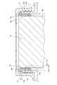
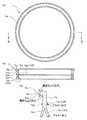
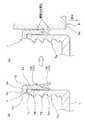
以下、図4に示した燃料タンクTにポンプモジュールPを取り付ける場合について説明する。図1は本発明に係るシール構造を示す断面説明図、図2において(a)はシール部材1の平面図、(b)は(a)におけるA−A断面図、(c)はシール部材1の部分詳細断面図、図3はシール部材1に対してポンプモジュールPを取り付ける場合の側面説明図である。
【0015】
図1及び図4を参照して、燃料タンクTは、ブロー成形等によって成形される樹脂製のタンクであって、その上部には、上面に開口部Tbを有する円筒部Taが形成されている。開口部Tb周りの周縁部Tcは、シール部材1のシール部1cに接するシール面としての機能を担う。そして、円筒部Taの外周面には雄ねじTdが螺設されている。
【0016】
次いで、ポンプモジュールPは、図示しないポンプ部を内蔵した円筒形状を呈する筐体(本体Pa)と、この本体Paの上部に形成される円板状のフランジ部Pbとを有した構成からなる。なお、フランジ部Pbの上面には、燃料を外部へ送り出すための吐出口が形成されるが、図では省略している。本体Pa及びフランジ部Pbは合成樹脂材等により成形されている。
【0017】
シール部材1は、燃料タンクTの開口部TbとポンプモジュールPとの間に介設される。シール部材1は、弾性を有する部材であり、例えば、アクリロニトリル−ブタジエンゴムとポリ塩化ビニルとの混合材料等から成形されたゴム部材として構成される。シール部材1は、図2に示すように、略鉛直状に、且つ環状に形成される本体部1aと、この本体部1aの上端から径方向の外側に向けて水平状に形成される環状のフランジ部1bと、を有した形状からなる。
【0018】
フランジ部1bの上面及び下面には、それぞれ断面視して半円状に突型となるシール部1c1,1c2が全周にわたって形成されている。一方、本体部1aにおいて、その内周面及び外周面における上下方向に関する略中央部には、断面視して頂点が斜め下方向に位置し、頂点角が鋭角となる三角形状の嵌合腕部1d1,1d2が、それぞれ全周にわたって形成されている。また、本体部1aの下端は全周にわたり、内周側と外周側に向けて二股となるように分岐形成されており、内周側に向かう形成部位が嵌合脚部1e1として、外周側に向かう形成部位が嵌合脚部1e2として構成される。
【0019】
図1に示すように、燃料タンクTへのポンプモジュールPの挿入が完了したときには、シール部1c1がフランジ部Pbの下面に弾性変形して密着し、シール部1c2が燃料タンクT側の周縁部Tcに弾性変形して密着することで、開口部Tbとフランジ部Pbとの間が封止(シール)される。また、嵌合腕部1d2及び嵌合脚部1e2が本体部1a寄りに弾性変形して円筒部Taの内周面に密着嵌合するとともに、嵌合腕部1d1及び嵌合脚部1e1も本体部1a寄りに弾性変形してポンプモジュールPの本体Paに密着嵌合し、本体Paを支持する。その後、キャップCを雄ねじTdに螺合することで、ポンプモジュールPは燃料タンクTに対して堅固に固定される。
【0020】
さて、シール部材1及びポンプモジュールPの取り付け態様としては、先にシール部材1を燃料タンクTの開口部Tbに取り付けてからポンプモジュールPを取り付けるという態様になっており、これら一連の取り付け作業は人手により行われる。このとき、シール部材1を開口部Tbに取り付けるに当たっては、シール部材1を十分に撓ませることが可能なので、前記したように嵌合腕部1d2及び嵌合脚部1e2を円筒部Taの内周面に密着嵌合させることは容易であり、シール部材1の取り付けは比較的スムースに行われる。
【0021】
しかし、開口部Tb周りに固定された状態のシール部材1に対してポンプモジュールPを燃料タンクTへ挿入するに当たっては、図3に示すように、その挿入過程において、本体Paとシール部材1の内周面(本実施形態では前記嵌合腕部1d1及び嵌合脚部1e1)との間に摩擦力が発生するため、この摩擦力が抵抗となって、ポンプモジュールPの挿入がスムースに行えないというおそれがある。
【0022】
ここで、前記嵌合腕部1d1及び嵌合脚部1e1において、ポンプモジュールPの本体Paと接面する部位を嵌合接面部1fというものとすると、例えば、前記摩擦力を低減させる手段としては、嵌合接面部1fの部位を摩擦係数の少ない材質から成形することが考えられる。しかし、一体に成形されるシール部材1を複数の材質をもって成形することはコスト的に不利である。
【0023】
そこで、本発明においては、シール対象部(本実施形態では開口部Tb周りの周縁部Tc及びポンプモジュールPのフランジ部Pb)を封止するシール部(本実施形態では1c1,1c2)と、嵌合対象部(本実施形態ではポンプモジュールPの本体Pa)を支持し、この嵌合対象部の嵌合途中において当該嵌合対象部との間で摩擦力を生じ得る嵌合接面部1f(本実施形態では嵌合腕部1d1及び嵌合脚部1e1の接面部)と、を一体に形成したシール部材1において、シール部(1c1,1c2)以外の部位における少なくとも嵌合接面部1fの表面粗さを、シール部(1c1,1c2)の表面粗さよりも大きくした構成としている。なお、本発明において、「嵌合接面部」とは、嵌合対象部が接面の面方向に沿って摺接する部位を指す。
【0024】
ここで、「表面粗さ」とは、「JIS B 0601−2001」に規定されるものをいう。この表面粗さを異ならせるに当たり、本実施形態では、シール性能を確保するべくシール部1c1,1c2を鏡面仕上げ加工(mirror polishing)された型面により成形し、シール部1c1,1c2以外の部位を全てブラスト加工された型面により成形している。これにより、容易にシール部材1において、シール部1c1,1c2と嵌合接面部1fとの間で表面粗さを異ならせることができる。なお、本実施形態では、金型のブラスト加工として「砥粒番号:#150」の噴射材を利用している。
【0025】
以上のシール部材1によれば、シール部1c1,1c2による所定のシール性能が維持され、且つ、嵌合接面部1fの表面がブラスト加工により多数の凹凸となって粗く成形されていることから、ポンプモジュールPの本体Paとの間で生ずる摩擦力が低減されることとなる。したがって、燃料タンクTへのポンプモジュールPの挿入が容易に行え、ポンプモジュールPに関する取り付け作業の効率が向上する。
【0026】
なお、嵌合接面部1fのみをブラスト加工し、嵌合接面部1fを除く全ての部位を鏡面仕上げ加工としても良いが、シール部材1における各角部に関しては、鏡面仕上げ加工とした場合には、金型での成形後にバリが発生しやすく、バリ取りの作業が別途必要となることがある。これに対して、シール部1c1,1c2のみを鏡面仕上げ加工による成形とし、その他の部位を全てブラスト加工による成形とすることで、バリの発生がなくなり、バリ取りの作業も不要となる。
【0027】
また、表面粗さを異ならせるに当たり、例えば、金型を全て鏡面仕上げ加工とし、シール部1c1,1c2の型面と嵌合接面部1fの型面とをそれぞれ砥粒番号の異なるバフ等により仕上げるという態様も可能である。しかし、嵌合接面部1fをブラスト加工することによりその表面粗さを、シール部1c1,1c2の表面粗さよりも大きくすることで、効果的な前記摩擦力の低減化が図れ、且つ、経済的にシール部材1を成形できることとなる。
【0028】
以上、本発明について好適な実施形態を説明した。説明した形態は、シール対象部及び嵌合対象部が、ポンプモジュールPのフランジ部Pb及び本体Paの場合であるが、シール対象部と嵌合対象部が別体の部材として構成されている場合であっても本発明は適用可能である。その他、本発明は、各構成要素の形状やレイアウト、個数等についてその主旨を逸脱しない範囲で適宜に設計変更が可能である。
【0029】
【発明の効果】
本発明によれば、所定のシール性能を確保しつつ、嵌合対象部を容易に嵌合接面部に対して嵌合させることができる。つまり、ポンプモジュールをスムースに燃料タンクの内部に挿入でき、ポンプモジュールの取り付け作業の効率が向上する。
【図面の簡単な説明】
【図1】本発明に係るシール構造を示す断面説明図である。
【図2】(a)はシール部材の平面図、(b)は(a)におけるA−A断面図、(c)はシール部材の部分詳細断面図である。
【図3】開口部に取り付けられたシール部材に対してポンプモジュールを取り付ける場合の側面説明図である。
【図4】樹脂製の燃料タンクに対するポンプモジュールの取り付け例を示す説明図である。
【符号の説明】
P ポンプモジュール
Pa 本体
Pb フランジ部
T 燃料タンク
Ta 円筒部
Tb 開口部
Tc 周縁部
1 シール部材
1c1,1c2 シール部
1f 嵌合接面部[0001]
BACKGROUND OF THE INVENTION
The presentinvention relates tosheet Lumpur structure.
[0002]
[Prior art]
As a unit of a fuel tank used in a vehicle or the like, there is a type in which a pump module for supplying fuel to an engine or the like is accommodated inside the fuel tank. FIG. 4 is an explanatory view showing an example of attachment of the pump module P to the resin fuel tank T. FIG.
[0003]
A cylindrical portion Ta having an opening Tb on the upper surface is formed on the upper portion of the fuel tank T. The pump module P has a configuration including a cylindrical main body Pa and a disk-like flange portion Pb formed on the upper portion of the main body Pa. The main body Pa is connected to the fuel tank T via the opening Tb. Is inserted inside.
[0004]
[0005]
Further, in the process of manually attaching the pump module P to the
[0006]
A male screw Td is screwed on the outer peripheral surface of the cylindrical portion Ta, and a cap C having a female screw Ca screwed on the inner peripheral surface thereof is screwed to the male screw Td, whereby the pump module P is fitted to the fuel tank T. Fix against. A structure in which a seal member is interposed between the opening of the fuel tank and the pump module is also disclosed in
[0007]
[Patent Document 1]
Japanese Patent Laid-Open No. 9-242637 (3rd and 4th pages, FIGS. 1 and 2)
[0008]
[Problems to be solved by the invention]
However, according to the sealing structure using the
[0009]
The present invention has been created to solve the above problems, it is an object of the insertion of the pump module to the fuel tank to provide a easy toluciferyl Lumpur structure.
[0010]
[Means for Solving the Problems]
In order to solve the above problems, the present invention is interposed between an opening formed in a fuel tank and a pump module attached to the opening, and is formed in a vertical shape in a side view and an annular shape in a plan view. And a sealing structure using a seal member made of a rubber material integrally formed with a flange portion having a ring shape in plan view and formed in a horizontal shape from the upper end of the main body portion toward the radially outer side. On the upper surface and the lower surface of the flange portion of the member, a seal portion having a projecting shape for sealing between the peripheral edge of the opening and the flange portion of the pump module is protruded, and the main body of the seal member A fitting contact surface portion that generates a frictional force with the main body of the pump module that is inserted into the fuel tank is formed on an inner peripheral surface of the portion, and the sealing member is configured to reduce the frictional force.before inThe surface roughness of Hamagose' face Upon larger than the surface roughness of the sealing portion, and the surface roughness of all sites except for the sealing portion is formed larger than the surface roughness of the sealing portion. Thereby, a fitting object part can be easily fitted with respect to a fitting contact surface part, ensuring predetermined sealing performance. That is, the pump module can be smoothly inserted into the fuel tank, and the efficiency of the installation work of the pump module is improved.
[0011]
In addition, if the seal part is formed by a mold surface that is mirror-finished, and at least the fitting contact surface part in a portion other than the seal part is formed by a blasted mold surface,it is easy. The surface roughness between them can be made different, and an economical sealing member is obtained.
[0014]
DETAILED DESCRIPTION OF THE INVENTION
Hereinafter, the case where the pump module P is attached to the fuel tank T shown in FIG. 4 will be described. FIG. 1 is a cross-sectional explanatory view showing a seal structure according to the present invention, FIG. 2 (a) is a plan view of the
[0015]
Referring to FIGS. 1 and 4, the fuel tank T is a resin tank formed by blow molding or the like, and a cylindrical portion Ta having an opening Tb on the upper surface is formed on the upper portion thereof. . The peripheral edge portion Tc around the opening Tb serves as a seal surface that contacts the
[0016]
Next, the pump module P has a configuration including a cylindrical housing (main body Pa) having a pump portion (not shown) and a disk-shaped flange portion Pb formed on the upper portion of the main body Pa. In addition, although the discharge port for sending out a fuel outside is formed in the upper surface of the flange part Pb, it is abbreviate | omitting in the figure. The main body Pa and the flange portion Pb are formed of a synthetic resin material or the like.
[0017]
The
[0018]
On the upper surface and the lower surface of the
[0019]
As shown in FIG. 1, when the insertion of the pump module P into the fuel tank T is completed, the
[0020]
Now, as an attachment mode of the
[0021]
However, when the pump module P is inserted into the fuel tank T with respect to the
[0022]
Here, in the fitting arm portion 1d1 and the fitting leg portion 1e1 , assuming that a portion in contact with the main body Pa of the pump module P is a fitting
[0023]
Therefore, in the present invention, seal portions (1c1 and 1c2 in the present embodiment) for sealing the seal target portions (the peripheral portion Tc around the opening Tb and the flange portion Pb of the pump module P in the present embodiment) The fitting
[0024]
Here, “surface roughness” refers to that defined in “JIS B 0601-2001”. Upon varying the surface roughness, in the present embodiment, the sealing
[0025]
According to the sealing
[0026]
It should be noted that only the fitting
[0027]
Further, when making the surface roughness different, for example, all the molds are mirror-finished, and the mold surfaces of the
[0028]
The preferred embodiments of the present invention have been described above. The described form is a case where the sealing target part and the fitting target part are the flange part Pb and the main body Pa of the pump module P, but the sealing target part and the fitting target part are configured as separate members. Even so, the present invention is applicable. In addition, the present invention can be appropriately changed in design without departing from the gist, layout, number, and the like of each component.
[0029]
【The invention's effect】
According to the present invention, it is possible to easily fit the fitting target portion to the fitting contact surface portion while ensuring a predetermined sealing performance. That is, the pump module can be smoothly inserted into the fuel tank, and the efficiency of the installation work of the pump module is improved.
[Brief description of the drawings]
FIG. 1 is an explanatory cross-sectional view showing a seal structure according to the present invention.
2A is a plan view of a seal member, FIG. 2B is a cross-sectional view taken along line AA in FIG. 2A, and FIG. 2C is a partial detailed cross-sectional view of the seal member;
FIG. 3 is an explanatory side view when the pump module is attached to the seal member attached to the opening.
FIG. 4 is an explanatory view showing an example of attachment of a pump module to a resin fuel tank.
[Explanation of symbols]
P pump module Pa body Pb flange portion T fuel tank Ta cylindrical portion Tb opening Tc periphery first sealing
Claims (1)
Translated fromJapanese前記シール部材のフランジ部の上面および下面には、前記開口部の周縁と前記ポンプモジュールのフランジ部との間を封止するための突型形状を呈したシール部が突設され、
前記シール部材の本体部の内周面には、前記燃料タンク内に挿入される前記ポンプモジュールの本体との間で摩擦力を生じる嵌合接面部が形成され、
前記摩擦力が低減されるように、前記シール部材において前記嵌合接面部の表面粗さを前記シール部の表面粗さよりも大きく形成するにあたり、前記シール部を除く全ての部位の表面粗さを前記シール部の表面粗さよりも大きく形成したことを特徴とするシール構造。A body part that is interposed between an opening formed in the fuel tank and a pump module attached to the opening, and is formed in a vertical shape in a side view and a ring shape in plan view, and a diameter from the upper end of the body part A seal structure using a seal member made of a rubber material integrally formed with an annular flange portion that is formed horizontally in the direction toward the outside in the direction,
On the upper surface and the lower surface of the flange portion of the seal member, a seal portion having a projecting shape for sealing between the periphery of the opening and the flange portion of the pump module is provided,
On the inner peripheral surface of the main body portion of the seal member, a fitting contact surface portion that generates a frictional force with the main body of the pump module inserted into the fuel tank is formed.
Informing the surface roughness of the fitting contact surface portion larger than the surface roughness of the seal portion in the seal member so that the frictional force is reduced,the surface roughness of all portions except the seal portion is set. A seal structure characterized by being formed to be larger than the surface roughness of the seal portion.
Priority Applications (1)
| Application Number | Priority Date | Filing Date | Title |
|---|---|---|---|
| JP2003069497AJP4381702B2 (en) | 2003-03-14 | 2003-03-14 | Seal structure |
Applications Claiming Priority (1)
| Application Number | Priority Date | Filing Date | Title |
|---|---|---|---|
| JP2003069497AJP4381702B2 (en) | 2003-03-14 | 2003-03-14 | Seal structure |
Publications (2)
| Publication Number | Publication Date |
|---|---|
| JP2004278622A JP2004278622A (en) | 2004-10-07 |
| JP4381702B2true JP4381702B2 (en) | 2009-12-09 |
Family
ID=33286517
Family Applications (1)
| Application Number | Title | Priority Date | Filing Date |
|---|---|---|---|
| JP2003069497AExpired - LifetimeJP4381702B2 (en) | 2003-03-14 | 2003-03-14 | Seal structure |
Country Status (1)
| Country | Link |
|---|---|
| JP (1) | JP4381702B2 (en) |
Families Citing this family (7)
| Publication number | Priority date | Publication date | Assignee | Title |
|---|---|---|---|---|
| US7854434B2 (en) | 2007-04-12 | 2010-12-21 | Ti Group Automotive Systems, L.L.C. | Ring seal with axially-opposed radially-offset seal beads |
| US7975870B2 (en) | 2007-08-29 | 2011-07-12 | Ti Group Automotive Systems, L.L.C. | Ring seal having sealing lobes |
| KR100931051B1 (en) | 2008-03-20 | 2009-12-10 | 현대자동차주식회사 | Fuel Pump Mount Unit for Plastic Fuel Tank |
| US8910815B2 (en) | 2008-04-14 | 2014-12-16 | Ti Group Automotive Systems, L.L.C. | Cover for fuel system component and method of making |
| JP5245709B2 (en)* | 2008-10-16 | 2013-07-24 | トヨタ紡織株式会社 | Fastening structure and fluid filter including the same |
| US8419021B2 (en) | 2008-10-31 | 2013-04-16 | Ti Group Automotive Systems, L.L.C. | Ring seal with insert |
| US8967424B2 (en) | 2011-02-10 | 2015-03-03 | Honda Motor Co., Ltd. | Sealing structure of fuel tank and vehicle provided with same |
- 2003
- 2003-03-14JPJP2003069497Apatent/JP4381702B2/ennot_activeExpired - Lifetime
Also Published As
| Publication number | Publication date |
|---|---|
| JP2004278622A (en) | 2004-10-07 |
Similar Documents
| Publication | Publication Date | Title |
|---|---|---|
| US8028999B2 (en) | Axle boot | |
| JP4381702B2 (en) | Seal structure | |
| EP2088352B1 (en) | Sealing device | |
| JP2933483B2 (en) | Housing cover and seal assembly | |
| JP2009255911A (en) | Opening cover of fuel tank, its forming method, and fuel tank assembly equipped with the opening cover | |
| US20130249235A1 (en) | Integrated floating overmolded snap-ring and seal for a plastic fuel housing assembly | |
| US20010045784A1 (en) | Rotary electric machine | |
| JP2013099995A (en) | Center bearing support | |
| JP4957937B2 (en) | Sealing device | |
| EP0727575A1 (en) | A shaft seal arrangement | |
| JP2931009B2 (en) | Sealing device and method of manufacturing sealing device | |
| JP2574263Y2 (en) | Dust cover | |
| JP4160927B2 (en) | Mold for synthetic resin compression molding | |
| JP2599362Y2 (en) | Sealing device | |
| CN210919550U (en) | Novel structure of oil-retaining bearing motor | |
| JPH0230257Y2 (en) | ||
| CN219796104U (en) | Socket joint | |
| JP2005325924A (en) | Sealing device | |
| CN221366459U (en) | Valve cap | |
| JPS6221813Y2 (en) | ||
| JPH0640439U (en) | Ball joint dust cover | |
| CN216382947U (en) | Pipeline connection structure and vehicle | |
| JP2004162830A (en) | Pulley made of resin with bearing | |
| JPS6221815Y2 (en) | ||
| JPS5828935Y2 (en) | Washer pump mounting structure |
Legal Events
| Date | Code | Title | Description |
|---|---|---|---|
| A621 | Written request for application examination | Free format text:JAPANESE INTERMEDIATE CODE: A621 Effective date:20060313 | |
| A977 | Report on retrieval | Free format text:JAPANESE INTERMEDIATE CODE: A971007 Effective date:20081023 | |
| A131 | Notification of reasons for refusal | Free format text:JAPANESE INTERMEDIATE CODE: A131 Effective date:20081028 | |
| A521 | Request for written amendment filed | Free format text:JAPANESE INTERMEDIATE CODE: A523 Effective date:20081219 | |
| A131 | Notification of reasons for refusal | Free format text:JAPANESE INTERMEDIATE CODE: A131 Effective date:20090317 | |
| A521 | Request for written amendment filed | Free format text:JAPANESE INTERMEDIATE CODE: A523 Effective date:20090518 | |
| TRDD | Decision of grant or rejection written | ||
| A01 | Written decision to grant a patent or to grant a registration (utility model) | Free format text:JAPANESE INTERMEDIATE CODE: A01 Effective date:20090901 | |
| A01 | Written decision to grant a patent or to grant a registration (utility model) | Free format text:JAPANESE INTERMEDIATE CODE: A01 | |
| A61 | First payment of annual fees (during grant procedure) | Free format text:JAPANESE INTERMEDIATE CODE: A61 Effective date:20090916 | |
| FPAY | Renewal fee payment (event date is renewal date of database) | Free format text:PAYMENT UNTIL: 20121002 Year of fee payment:3 | |
| R150 | Certificate of patent or registration of utility model | Ref document number:4381702 Country of ref document:JP Free format text:JAPANESE INTERMEDIATE CODE: R150 Free format text:JAPANESE INTERMEDIATE CODE: R150 | |
| FPAY | Renewal fee payment (event date is renewal date of database) | Free format text:PAYMENT UNTIL: 20131002 Year of fee payment:4 | |
| R250 | Receipt of annual fees | Free format text:JAPANESE INTERMEDIATE CODE: R250 | |
| R250 | Receipt of annual fees | Free format text:JAPANESE INTERMEDIATE CODE: R250 | |
| R250 | Receipt of annual fees | Free format text:JAPANESE INTERMEDIATE CODE: R250 | |
| R250 | Receipt of annual fees | Free format text:JAPANESE INTERMEDIATE CODE: R250 | |
| R250 | Receipt of annual fees | Free format text:JAPANESE INTERMEDIATE CODE: R250 | |
| R250 | Receipt of annual fees | Free format text:JAPANESE INTERMEDIATE CODE: R250 | |
| R250 | Receipt of annual fees | Free format text:JAPANESE INTERMEDIATE CODE: R250 | |
| R250 | Receipt of annual fees | Free format text:JAPANESE INTERMEDIATE CODE: R250 | |
| R250 | Receipt of annual fees | Free format text:JAPANESE INTERMEDIATE CODE: R250 | |
| R250 | Receipt of annual fees | Free format text:JAPANESE INTERMEDIATE CODE: R250 | |
| R250 | Receipt of annual fees | Free format text:JAPANESE INTERMEDIATE CODE: R250 | |
| EXPY | Cancellation because of completion of term |