JP4378221B2 - Process cartridge and electrophotographic image forming apparatus - Google Patents
Process cartridge and electrophotographic image forming apparatusDownload PDFInfo
- Publication number
- JP4378221B2 JP4378221B2JP2004161219AJP2004161219AJP4378221B2JP 4378221 B2JP4378221 B2JP 4378221B2JP 2004161219 AJP2004161219 AJP 2004161219AJP 2004161219 AJP2004161219 AJP 2004161219AJP 4378221 B2JP4378221 B2JP 4378221B2
- Authority
- JP
- Japan
- Prior art keywords
- cartridge
- main body
- process cartridge
- developer
- apparatus main
- Prior art date
- Legal status (The legal status is an assumption and is not a legal conclusion. Google has not performed a legal analysis and makes no representation as to the accuracy of the status listed.)
- Expired - Fee Related
Links
Images


Classifications
- G—PHYSICS
- G03—PHOTOGRAPHY; CINEMATOGRAPHY; ANALOGOUS TECHNIQUES USING WAVES OTHER THAN OPTICAL WAVES; ELECTROGRAPHY; HOLOGRAPHY
- G03G—ELECTROGRAPHY; ELECTROPHOTOGRAPHY; MAGNETOGRAPHY
- G03G21/00—Arrangements not provided for by groups G03G13/00 - G03G19/00, e.g. cleaning, elimination of residual charge
- G03G21/16—Mechanical means for facilitating the maintenance of the apparatus, e.g. modular arrangements
- G03G21/18—Mechanical means for facilitating the maintenance of the apparatus, e.g. modular arrangements using a processing cartridge, whereby the process cartridge comprises at least two image processing means in a single unit
- G03G21/1803—Arrangements or disposition of the complete process cartridge or parts thereof
- G03G21/1814—Details of parts of process cartridge, e.g. for charging, transfer, cleaning, developing
- G—PHYSICS
- G03—PHOTOGRAPHY; CINEMATOGRAPHY; ANALOGOUS TECHNIQUES USING WAVES OTHER THAN OPTICAL WAVES; ELECTROGRAPHY; HOLOGRAPHY
- G03G—ELECTROGRAPHY; ELECTROPHOTOGRAPHY; MAGNETOGRAPHY
- G03G15/00—Apparatus for electrographic processes using a charge pattern
- G—PHYSICS
- G03—PHOTOGRAPHY; CINEMATOGRAPHY; ANALOGOUS TECHNIQUES USING WAVES OTHER THAN OPTICAL WAVES; ELECTROGRAPHY; HOLOGRAPHY
- G03G—ELECTROGRAPHY; ELECTROPHOTOGRAPHY; MAGNETOGRAPHY
- G03G15/00—Apparatus for electrographic processes using a charge pattern
- G03G15/06—Apparatus for electrographic processes using a charge pattern for developing
- G03G15/08—Apparatus for electrographic processes using a charge pattern for developing using a solid developer, e.g. powder developer
- G03G15/0822—Arrangements for preparing, mixing, supplying or dispensing developer
- G03G15/0848—Arrangements for testing or measuring developer properties or quality, e.g. charge, size, flowability
- G03G15/0849—Detection or control means for the developer concentration
- G03G15/0855—Detection or control means for the developer concentration the concentration being measured by optical means
- G—PHYSICS
- G03—PHOTOGRAPHY; CINEMATOGRAPHY; ANALOGOUS TECHNIQUES USING WAVES OTHER THAN OPTICAL WAVES; ELECTROGRAPHY; HOLOGRAPHY
- G03G—ELECTROGRAPHY; ELECTROPHOTOGRAPHY; MAGNETOGRAPHY
- G03G15/00—Apparatus for electrographic processes using a charge pattern
- G03G15/06—Apparatus for electrographic processes using a charge pattern for developing
- G03G15/08—Apparatus for electrographic processes using a charge pattern for developing using a solid developer, e.g. powder developer
- G03G15/0822—Arrangements for preparing, mixing, supplying or dispensing developer
- G03G15/0863—Arrangements for preparing, mixing, supplying or dispensing developer provided with identifying means or means for storing process- or use parameters, e.g. an electronic memory
- G—PHYSICS
- G03—PHOTOGRAPHY; CINEMATOGRAPHY; ANALOGOUS TECHNIQUES USING WAVES OTHER THAN OPTICAL WAVES; ELECTROGRAPHY; HOLOGRAPHY
- G03G—ELECTROGRAPHY; ELECTROPHOTOGRAPHY; MAGNETOGRAPHY
- G03G15/00—Apparatus for electrographic processes using a charge pattern
- G03G15/06—Apparatus for electrographic processes using a charge pattern for developing
- G03G15/08—Apparatus for electrographic processes using a charge pattern for developing using a solid developer, e.g. powder developer
- G03G15/0822—Arrangements for preparing, mixing, supplying or dispensing developer
- G03G15/0865—Arrangements for supplying new developer
- G—PHYSICS
- G03—PHOTOGRAPHY; CINEMATOGRAPHY; ANALOGOUS TECHNIQUES USING WAVES OTHER THAN OPTICAL WAVES; ELECTROGRAPHY; HOLOGRAPHY
- G03G—ELECTROGRAPHY; ELECTROPHOTOGRAPHY; MAGNETOGRAPHY
- G03G21/00—Arrangements not provided for by groups G03G13/00 - G03G19/00, e.g. cleaning, elimination of residual charge
- G03G21/16—Mechanical means for facilitating the maintenance of the apparatus, e.g. modular arrangements
- G03G21/18—Mechanical means for facilitating the maintenance of the apparatus, e.g. modular arrangements using a processing cartridge, whereby the process cartridge comprises at least two image processing means in a single unit
- G03G21/1839—Means for handling the process cartridge in the apparatus body
- G03G21/1867—Means for handling the process cartridge in the apparatus body for electrically connecting the process cartridge to the apparatus, electrical connectors, power supply
- G—PHYSICS
- G03—PHOTOGRAPHY; CINEMATOGRAPHY; ANALOGOUS TECHNIQUES USING WAVES OTHER THAN OPTICAL WAVES; ELECTROGRAPHY; HOLOGRAPHY
- G03G—ELECTROGRAPHY; ELECTROPHOTOGRAPHY; MAGNETOGRAPHY
- G03G21/00—Arrangements not provided for by groups G03G13/00 - G03G19/00, e.g. cleaning, elimination of residual charge
- G03G21/16—Mechanical means for facilitating the maintenance of the apparatus, e.g. modular arrangements
- G03G21/18—Mechanical means for facilitating the maintenance of the apparatus, e.g. modular arrangements using a processing cartridge, whereby the process cartridge comprises at least two image processing means in a single unit
- G03G21/1875—Mechanical means for facilitating the maintenance of the apparatus, e.g. modular arrangements using a processing cartridge, whereby the process cartridge comprises at least two image processing means in a single unit provided with identifying means or means for storing process- or use parameters, e.g. lifetime of the cartridge
- G03G21/1878—Electronically readable memory
- G03G21/1882—Electronically readable memory details of the communication with memory, e.g. wireless communication, protocols
- G03G21/1885—Electronically readable memory details of the communication with memory, e.g. wireless communication, protocols position of the memory; memory housings; electrodes
Landscapes
- Physics & Mathematics (AREA)
- General Physics & Mathematics (AREA)
- Engineering & Computer Science (AREA)
- Computer Vision & Pattern Recognition (AREA)
- Computer Networks & Wireless Communication (AREA)
- Electrophotography Configuration And Component (AREA)
- Electrostatic Charge, Transfer And Separation In Electrography (AREA)
- Photoreceptors In Electrophotography (AREA)
- Dry Development In Electrophotography (AREA)
Description
Translated fromJapanese本発明は、プロセスカートリッジ及び前記プロセスカートリッジが着脱可能な電子写真画像形成装置に関する。 The present invention relates to a process cartridge and an electrophotographic image forming apparatus to which the process cartridge is detachable.
ここで、電子写真画像形成装置とは、電子写真画像形成方式を用いて記録媒体(例えば、記録紙、OHPシート等)に画像を形成するものである。電子写真画像形成装置の例としては、例えば、電子写真複写機、電子写真プリンタ(例えば、レーザプリンタ、LEDプリンタ等)、ファクシミリ装置、ワードプロセッサ及びこれらの複合機(マルチファンクションプリンター等)が含まれる。 Here, the electrophotographic image forming apparatus forms an image on a recording medium (for example, recording paper, OHP sheet, etc.) using an electrophotographic image forming system. Examples of the electrophotographic image forming apparatus include, for example, an electrophotographic copying machine, an electrophotographic printer (for example, a laser printer, an LED printer, etc.), a facsimile apparatus, a word processor, and a complex machine (multifunction printer, etc.) thereof.
また、プロセスカートリッジ(以下「カートリッジ」と称す)とは、少なくとも現像手段(現像部材)と電子写真感光体ドラムとを一体的にカートリッジ化して電子写真画像形成装置本体に着脱可能とするものをいう。 The process cartridge (hereinafter referred to as “cartridge”) refers to a cartridge in which at least the developing means (developing member) and the electrophotographic photosensitive drum are integrated into a cartridge so as to be detachable from the main body of the electrophotographic image forming apparatus. .
従来、電子写真画像形成装置(以下「画像形成装置」と称す。)においては、電子写真感光体ドラム(以下「感光体ドラム」と称す)に形成した静電潜像を、現像装置によって現像剤を用いて現像する。 Conventionally, in an electrophotographic image forming apparatus (hereinafter referred to as “image forming apparatus”), an electrostatic latent image formed on an electrophotographic photosensitive drum (hereinafter referred to as “photosensitive drum”) is developed by a developing device using a developer. Develop using.
また、プロセスカートリッジ(以下「カートリッジ」と称す)を採用する画像形成装置においては、装置のメンテナンスを操作者自身が行うことができる。そこで、このカートリッジ方式は、格段に操作性を向上させることができる。 In an image forming apparatus that employs a process cartridge (hereinafter referred to as “cartridge”), the operator can perform maintenance of the apparatus. Therefore, this cartridge system can remarkably improve the operability.
そして、操作者の利便性を向上させる技術の一つとして、カートリッジが備える現像剤収納部に充填された現像剤の残量を操作者に知らせるための現像剤残量検知手段が考案されている。そのような手段の中には、ある一定時間内に、現像剤収納部内を通過する光の透過時間を測定することで、現像剤収納部内の現像剤の残量を検知する手段がある。 As one of the techniques for improving the convenience for the operator, a developer remaining amount detecting means has been devised for notifying the operator of the remaining amount of the developer filled in the developer accommodating portion provided in the cartridge. . Among such means, there is a means for detecting the remaining amount of developer in the developer storage unit by measuring the transmission time of light passing through the developer storage unit within a certain time.
このような光透過式の現像剤残量検知手段(以下「残量検知手段」と称す)は、例えば、画像形成装置の本体側に配置された発光部及び受光部と、現像剤収納部に備えられた光透過部と、発光部から発光された検知光を発光部から光透過部及び光透過部から受光部へと導く光ガイドと、を有する。 Such light transmission type developer remaining amount detecting means (hereinafter referred to as “remaining amount detecting means”) includes, for example, a light emitting portion and a light receiving portion disposed on the main body side of the image forming apparatus, and a developer accommodating portion. And a light guide that guides detection light emitted from the light emitting unit from the light emitting unit to the light transmitting unit and from the light transmitting unit to the light receiving unit.
上記構成によれば、検知光が現像剤収納部内を通過することができる時間は現像剤残量に依存する。従って、その時間は現像剤残量が多ければ短く、少なければ長くなる。そして、検知光の通過時間を装置本体で計測することにより、現像剤収納部内の現像剤残量を推測することが可能となる(特許文献1参照)。 According to the above configuration, the time during which the detection light can pass through the developer accommodating portion depends on the remaining amount of the developer. Therefore, the time is shorter when the remaining amount of developer is larger, and longer when the remaining amount of developer is small. Then, by measuring the passage time of the detection light with the apparatus main body, it is possible to estimate the remaining amount of the developer in the developer storage unit (see Patent Document 1).
さらに、操作者の利便性を向上させる他の技術として、カートリッジに記憶素子(メモリ部材)を備えるものも考案されている。この記憶素子と装置本体との間で、画像品質に関する情報、カートリッジの製造や寿命(例えば、現像剤の残量)に関する情報、本体の稼働状態に関する情報などを相互に通信させる。これによって、画像形成装置あるいはカートリッジのメンテナンスを容易にし、利便性の向上を図ることができる(特許文献2参照)。 Further, as another technique for improving the convenience of the operator, a technique in which a cartridge is provided with a storage element (memory member) has been devised. The storage element and the apparatus main body communicate with each other information on image quality, information on the manufacture and life of the cartridge (for example, the remaining amount of developer), information on the operating state of the main body, and the like. Accordingly, maintenance of the image forming apparatus or the cartridge can be facilitated, and convenience can be improved (see Patent Document 2).
しかしながら、最近の画像形成装置には、利便性の向上と共に小型であることも求められている。そのため、小型化には画像形成装置内に大きな空間を占めるカートリッジの小
型化が必要である。特にカートリッジを複数備えるカラー画像形成装置においては、カートリッジの小型化は課題である。However, recent image forming apparatuses are also required to be compact with improved convenience. For this reason, it is necessary to reduce the size of the cartridge that occupies a large space in the image forming apparatus. In particular, in a color image forming apparatus including a plurality of cartridges, downsizing of the cartridge is a problem.
このことは、上述の残量検出手段や記憶素子といった操作者の利便性に寄与する機能を備えたカートリッジ及び画像形成装置においても同様である。
本発明は、上記従来技術を更に発展させたものである。 The present invention is a further development of the above prior art.
本発明の目的は、小型化を実現したプロセスカートリッジ、及び、前記プロセスカートリッジを着脱可能な電子写真画像形成装置を提供することにある。 An object of the present invention is to provide a process cartridge that has been reduced in size, and an electrophotographic image forming apparatus in which the process cartridge can be attached and detached.
本発明の他の目的は、検知光を入射する第一光ガイドの入射部と、検知光を出射する第二光ガイドの出射部との間の領域に、メモリ部材を配置することで、小型化を図ることができるプロセスカートリッジ、及び、前記プロセスカートリッジが着脱可能な電子写真画像形成装置を提供することにある。 Another object of the present invention is to arrange a memory member in a region between the incident portion of the first light guide that enters the detection light and the emission portion of the second light guide that emits the detection light. An object of the present invention is to provide a process cartridge that can be manufactured and an electrophotographic image forming apparatus to which the process cartridge can be attached and detached.
本発明の他の目的は、発光部と、前記発光部から発した検知光を受光する受光部と、本体電気接点と、一つの基板に集約することができる電子写真画像形成装置、及び、前記電子写真画像形成装置に装着可能なプロセスカートリッジを提供することにある。 Another object of the present invention is to provide a light emitting part, a light receiving part for receiving detection light emitted from the light emitting part, a main body electrical contact, an electrophotographic image forming apparatus that can be integrated on one substrate, and the above It is an object of the present invention to provide a process cartridge that can be mounted on an electrophotographic image forming apparatus.
上記目的を達成するために本発明に係るプロセスカートリッジにあっては、
発光部と、前記発光部から発せられた検知光を受光する受光部と、本体電気接点と、前記発光部、前記受光部、及び、前記本体電気接点を一体的に備えた本体基体と、を有する電子写真画像形成装置の装置本体に着脱可能なプロセスカートリッジであって、
電子写真感光体ドラムと、
前記電子写真感光体ドラムに形成された静電潜像を現像する現像部材と、
前記静電潜像を現像するために前記現像部材で用いられる現像剤を収納する現像剤収納容部を有するカートリッジ枠体と、
前記カートリッジ枠体の前記電子写真感光体ドラムの軸線方向一端側、および前記プロセスカートリッジが前記装置本体へ装着される装着方向先端側に設けられた第一光ガイドであって、前記プロセスカートリッジが前記装置本体に装着された際に前記発光部と対向して、前記検知光を入射させる入射部を有し、前記現像剤収納容器内の現像剤収納空間を横切るように前記検知光をガイドする第一光ガイドと、
前記カートリッジ枠体の前記一端側、および前記装着方向先端側に設けられた第二光ガイドであって、前記プロセスカートリッジが前記装置本体に装着された際に前記受光部と対向して、前記現像剤収納空間を通過した前記検知光を前記受光部へ出射させる出射部を有する第二光ガイドと、
前記カートリッジ枠体の前記一端側、および前記装着方向先端側に設けられた、前記装置本体と通信可能なメモリ部材であって、前記プロセスカートリッジが前記装置本体に装着された際の鉛直方向において、前記入射部を通る水平面と前記出射部を通る水平面との間に設けられた、前記プロセスカートリッジが前記装置本体に装着された際に前記本体電気接点と電気的に接続するカートリッジ電気接点を有するメモリ部材と、
を有し、
前記メモリ部材の少なくとも一部は、前記入射部と前記出射部とを結んだ直線を横切ることを特徴とする。
In order to achieve the above object, in the process cartridge according to the present invention,
A light emitting unit, a light receiving unit that receives the detection light was originatingSerare from the light emitting portion, and the main body electrical contact,said light emitting portion, the light receiving portion, and a body base having integrally the body electrical contact, A process cartridgethat can be attached to and detached froman apparatus main body of an electrophotographic image forming apparatus having:
An electrophotographic photosensitive drum;
A developing member for developing the electrostatic latent image formed on the electrophotographic photosensitive drum;
A cartridge frame having a developer accommodating portion for accommodating a developer used in the developing member for developing the electrostatic latent image;
Axial end sideof said electrophotographic photosensitive drum of the cartridge frame, and said a first light guide the process cartridgeis provided in the mounting direction front end side thatwill be mounted to the main assembly of the apparatus, said process cartridge is pre the opposite to the light emitting portion when attachedtoKiSo Okimoto bodyhas an entrance portion which Ruis incident the detection light, the developer accommodating said detection light across the developer storage space in the container A first light guide to guide,
Wherein one end of said cartridge frame, and said a second light guide provided in the mounting direction front end side, the opposite to the light receiving portionwhen said process cartridge is mounted to the frontKiSo Okimotobody, a second light guide having an emitting portion of the detecting light having passed through the developer accommodating space Ruis emitted to the light receiving unit,
A memory member provided on the one end side of the cartridge frame and on the front end side in the mounting direction and capable of communicating with the apparatus main body, in the vertical direction when the process cartridge is mounted on the apparatus main body, memory havinga main body electrical contact electrically cartridge electrical contactsthat connect when provided, said process cartridge is mounted to the main assembly of the apparatusbetween a horizontal plane passing through the horizontal plane and the emitting portion through said entrance portion A member,
I have a,
At least a part of the memory member crosses a straight line connecting the incident part and the emission part .
また、本発明に係る電子写真画像形成装置にあっては、
プロセスカートリッジを着脱可能であって、記録媒体に画像を形成するための電子写真画像形成装置において、
(i)発光部と、
(ii)前記発光部から発せられた検知光を受光する受光部と、
(iii)本体電気接点と、
(iv)前記発光部、前記受光部、及び、前記本体電気接点を一体的に備えた本体基体と、
(v)電子写真感光体ドラムと、前記電子写真感光体ドラムに形成された静電潜像を現像す
る現像部材と、前記静電潜像を現像するために前記現像部材で用いられる現像剤を収納する現像剤収納容部を有するカートリッジ枠体と、前記カートリッジ枠体の前記電子写真感光体ドラムの軸線方向一端側、および前記プロセスカートリッジが前記電子写真画像形成装置の装置本体へ装着される装着方向先端側に設けられた第一光ガイドであって、前記プロセスカートリッジが前記装置本体に装着された際に前記発光部と対向して、前記検知光を入射させる入射部を有し、前記現像剤収納容器内の現像剤収納空間を横切るように前記検知光をガイドする第一光ガイドと、前記カートリッジ枠体の前記一端側、および前記装着方向先端側に設けられた第二光ガイドであって、前記プロセスカートリッジが前記装置本体に装着された際に前記受光部と対向して、前記現像剤収納空間を通過した前記検知光を前記受光部へ出射させる出射部を有する第二光ガイドと、前記カートリッジ枠体の前記一端側、および前記装着方向先端側に設けられた、前記装置本体と通信可能なメモリ部材であって、前記プロセスカートリッジが前記装置本体に装着された際の鉛直方向において、前記入射部を通る水平面と前記出射部を通る水平面との間に設けられた、前記プロセスカートリッジが前記装置本体に装着された際に前記本体電気接点と電気的に接続するカートリッジ電気接点を有するメモリ部材と、を有し、前記メモリ部材の少なくとも一部は、前記入射部と前記出射部とを結んだ直線を横切ることを特徴とするプロセスカートリッジを取り外し可能に装着する装着手段と、
(vi)前記記録媒体を搬送するための搬送手段と、
を有することを特徴とする。
In the electrophotographic image forming apparatus according to the present invention,
In an electrophotographic image forming apparatus for detaching a process cartridge and forming an image on a recording medium,
(i) a light emitting unit;
(ii) a light receiving unit that receives the detection light was originatingSerare from the light emitting portion,
(iii) the body electrical contacts;
(iv)a main body base body integrally including the light emitting section, the light receiving section, and the main body electrical contacts;
(v) an electrophotographic photosensitive drum, a developing member that develops the electrostatic latent image formed on the electrophotographic photosensitive drum, and a developer that is used in the developing member to develop the electrostatic latent image. a cartridge frame having a developer accommodating capacity portion for housing, mounting the axial direction one end sideof said electrophotographic photosensitive drum of the cartridge frame, and said process cartridgeis Ruis mounted into the apparatus main assemblyof theelectrophotographic image forming apparatus a first light guide provided on the forward end side, the opposite to the light emitting portionwhen said process cartridge is mounted to the frontKiSo Okimoto bodyhas an entrance portion which Ruis incident the detection light A first light guide that guides the detection light so as to cross the developer storage space in the developer storage container, and a second light guide provided on the one end side of the cartridge frame and on the front end side in the mounting direction. A guide, the opposite to the light receiving portionwhen said process cartridge is mounted to the frontKiSo Okimotobody, the emitting portion of the detecting light having passed through the developer accommodating space Ruis emitted to the light receiving portion A memory member provided on the one end side of the cartridge frame and on the front end side in the mounting direction and capable of communicating with the apparatus main body, wherein the process cartridge is mounted on the apparatus main body. in the vertical direction in the said horizontal plane passing through the incident portion and provided betweenthe horizontal plane passing through the exitportion, the main body electrical contact electrically connected when the process cartridge is mounted to the main assemblypossess a memory member, a having a cartridge electrical contacttothe at least a portion of the memory member, characterized in that cross the straight line connecting the said entrance portion and the exit portion A mounting means capable mounted remove the process cartridge,
(vi ) transport means for transporting the recording medium;
It is characterized by having.
本発明によれば、発光部、受光部および本体電気接点を、本体基体に一体的に配置できる。これにより、無駄な電気配線もなく、部品をコンパクトに集約して配置することができる。従って、電子写真画像形成装置において、部品点数の削減、小型化を可能とすることができる。
According to the present invention, thelight emitting unit, the light receiving unit, and the main body electrical contact can be integrally disposed on the main body base. Thereby, there is no useless electric wiring and components can be arranged in a compact manner. Therefore, in the electrophotographic image forming apparatus, the number of partscan bereduced and the sizecan bereduced .
以下に図面を参照して、この発明を実施するための最良の形態を例示的に説明する。ただし、この実施の形態に記載されている構成部品の材質、形状、その相対配置などは、特に特定的な記載がない限りは、この発明の範囲をそれらのみに限定する趣旨のものではない。また、以下の説明で一度説明した部材についての材質、形状などは、特に改めて記載しない限り初めの説明と同様のものである。 The best mode for carrying out the present invention will be exemplarily described below with reference to the drawings. However, the material, shape, relative arrangement, and the like of the component parts described in this embodiment are not intended to limit the scope of the present invention only to those unless otherwise specified. Further, the materials, shapes, etc. of the members once described in the following description are the same as those in the first description unless otherwise described.
図1〜図17を参照して、本実施の形態に係るカートリッジ及び画像形成装置について説明する。 A cartridge and an image forming apparatus according to the present embodiment will be described with reference to FIGS.
[画像形成装置の全体の説明]
まずカラー画像形成装置の全体構成について、図2を用いて説明する。図2は、本実施の形態に係る電子写真プロセスを利用した画像形成装置の一形態であるカラーレーザープリンタの概略断面図である。[Overall Description of Image Forming Apparatus]
First, the overall configuration of the color image forming apparatus will be described with reference to FIG. FIG. 2 is a schematic cross-sectional view of a color laser printer which is an embodiment of an image forming apparatus using the electrophotographic process according to the present embodiment.
図2に示すように、カラーレーザープリンタ(以下「プリンタ」と称す)100は、イエロー(Y)色の現像剤を有するイエローカートリッジ(7Y)、マゼンタ(M)色の現像剤を有するマゼンタカートリッジ(7M)、シアン(C)色の現像剤を有するシアンカートリッジ(7C)、ブラック(K)色の現像剤を有するブラックカートリッジ(7K)を各々取り外し可能に装着する装着部100Aを有する。また、前記装着部に装着されたカートリッジ7(7M、7Y、7C、7K)で現像され、多重転写されたカラー画像を保持する中間転写体5を有する。そして、中間転写体5は、給送部から給送された記録媒体Pに、前記カラー画像を転写する。 As shown in FIG. 2, a color laser printer (hereinafter referred to as “printer”) 100 includes a yellow cartridge (7Y) having a yellow (Y) developer and a magenta cartridge (magenta cartridge having a magenta (M) developer. 7M), a cyan cartridge (7C) having a cyan (C) color developer, and a black cartridge (7K) having a black (K) developer, each having a mounting
電子写真感光体ドラム(以下、「感光体ドラム」と称す)1(1Y、1M、1C、1K)は、駆動手段(不図示)によって、図2に示すように反時計回りに回転駆動される。 An electrophotographic photosensitive drum (hereinafter referred to as “photosensitive drum”) 1 (1Y, 1M, 1C, 1K) is rotationally driven counterclockwise as shown in FIG. 2 by driving means (not shown). .
感光体ドラム1の周囲には、その回転方向にしたがって順に、感光体ドラム1周面を均一に帯電する帯電部材としての帯電ローラ2(2Y、2M、2C、2K)、画像情報に基づいてレーザービームを照射し、前記帯電ローラ2によって帯電された感光体ドラム1上に静電潜像を形成するスキャナユニット3(3Y、3M、3C、3K)を有する。また、前記潜像を現像する第二枠体4(4Y、4M、4C、4K)を有する。そして、各感光体ドラム1周面上の現像剤像を一次転写部T1で中間転写体5に転写させる一次転写ローラ12(12Y、12M、12C、12K)を有する。また、転写後の感光体ドラム1周面に残った現像剤を除去するクリーニングブレード60を有する第一枠体6(6Y、6M、6C、6K)が配置されている。尚、前記転写ローラ12は、画像形成装置本体Aに設けられている。 A charging roller 2 (2Y, 2M, 2C, 2K) serving as a charging member that uniformly charges the circumferential surface of the
中間転写体5に転写された現像剤像は、二次転写部T2において、二次転写ローラ13により記録媒体Pへさらに転写される。現像剤像が転写された記録媒体Pは、定着器8において現像剤像を定着される。そして、排出ローラ対25によって装置上面の排出トレイ26へ排出される。 The developer image transferred to the
カートリッジ7は、前述した感光体ドラム1、帯電部材2、第二枠体4、第一枠体6を有する。また、プリンタ100は、中間転写体5と一体の開閉カバー11(図6)を有する。そして、カートリッジ7はこの開閉カバー11を開いた状態で、感光体ドラム1を手前にして、プリンタ100への着脱を行う。 The
次にプリンタ100、及びカートリッジ7の各部の構成について図1〜図3を参照して
説明する。Next, the configuration of each part of the
図3は、カートリッジ7の構成を説明するための断面図である。なお、各色の構成が同一の場合は、イエロー現像剤を有するカートリッジ7Yについてのみ説明し、その他の色のカートリッジについては説明を省略する。 FIG. 3 is a cross-sectional view for explaining the configuration of the
まず、カートリッジの有する各部について説明する。 First, each part of the cartridge will be described.
[感光体ドラム]
感光体ドラム1(1Y)は、例えば、アルミシリンダの外周面に有機光導電体層(OPC感光体)を塗布したものである。感光体ドラム1は、その両端部を支持部材によって回転自在に支持されている。そして感光体ドラム1は、第一枠体6に支持されている。[Photosensitive drum]
The photosensitive drum 1 (1Y) is obtained by, for example, applying an organic photoconductive layer (OPC photosensitive member) to the outer peripheral surface of an aluminum cylinder. Both ends of the
[帯電部材]
帯電ローラ2(2Y)は、接触帯電方式を用いた帯電部材として、ローラ状に形成された導電性の帯電ローラ2を用いる。そして、前記ローラ2を感光体ドラム1周面に当接させるとともに、ローラ2に帯電バイアスを印加する。これにより、感光体ドラム1周面を一様に帯電する。帯電ローラ2も第一枠体6に設けられている。[Charging member]
The charging roller 2 (2Y) uses a
[第二枠体]
第二枠体4(4Y)は、図3に示すように前記潜像を可視像化するためのイエロー色の現像剤を収容した現像剤収納部41を有する。また、現像部材としての現像ローラ40、搬送部材42、供給ローラ43、及び、現像ブレード44を有する。即ち、第二枠体4は、現像ローラ40を支持して、前記現像ローラ40によって潜像の現像に用いられる現像剤tを収納する現像剤収納部40を有する。そして、第一枠体6と回動可能に結合されている。[Second frame]
As shown in FIG. 3, the second frame 4 (4Y) has a
現像剤収納部41内の現像剤は、現像剤を搬送する搬送部材42が反時計回り(図3に示すX方向)に回転することで、現像剤供給ローラ43へ送り込まれる。ここで供給ローラ43は、現像ローラ40に現像剤を供給する。供給ローラ43と、現像ローラ40の外周に圧接された現像ブレード44とによって、時計回り(図3に示すY方向)に回転する現像ローラ40(図3)の外周に現像剤が塗布される。なお、供給ローラ43は芯金部とスポンジ部からなる弾性ローラである。 The developer in the
そして、前記現像ローラ40に現像バイアスが印加されることにより、感光体ドラム1に静電潜像に応じて現像剤像が現像される。即ち、現像ローラ40は、感光体ドラム1に形成された静電潜像を現像する。 Then, by applying a developing bias to the developing
次に、画像形成装置本体Aの有する各部について説明する。 Next, each part of the image forming apparatus main body A will be described.
[露光手段]
露光手段であるスキャナユニット3(3Y)は、画像信号がレーザダイオード(不図示)に与えられる。そして、このレーザダイオードが画像信号に対応する画像光を、スキャナモータ(不図示)によって高連回転されるポリゴンミラー9(9Y)へ照射する。ミラー9で反射した画像光は、結像レンズ(不図示)を介して一定連度で回転する感光体ドラム1の表面を選択的に露光する。これによって、感光体ドラム1上に静電潜像を形成する。[Exposure means]
In the scanner unit 3 (3Y) as an exposure unit, an image signal is given to a laser diode (not shown). Then, the laser diode irradiates image light corresponding to the image signal onto the polygon mirror 9 (9Y) which is rotated at a high speed by a scanner motor (not shown). The image light reflected by the mirror 9 selectively exposes the surface of the
[中間転写体]
中間転写体5は、カラー画像形成動作時に各現像ローラ40により現像された感光体ド
ラム1円周上の現像剤像を多重転写する。そのため、転写体5は、感光体ドラム1の外周速度と同期して、時計回り(図2)に回転する。[Intermediate transfer member]
The
感光体ドラム1に形成された現像剤像は、一次転写部T1において転写体5上に多重転写される。これは、転写体5を挟んで感光体ドラム1と対向する位置に配置され電圧を印加された一次転写ローラ12(12Y、12M、12C、12K)によって行われる。なお、一次転写部T1は、感光体ドラム1と転写ローラ12とが転写体5を挟んで対向する領域をいう。 The developer image formed on the
多重転写を受けた転写体5は、二次転写部T2において、電圧を印加された二次転写ローラ13との間に記録媒体Pを挟み込み搬送する。そして、転写体5上のカラー画像は記録媒体Pに一括転写される。 The
本実施の形態に係る転写体5は、シームレス樹脂ベルトで構成されている。そして、転写体5は、駆動ローラ14、対向ローラ15、テンションローラ16の三軸で張架されている。 The
また、転写体5は、装置本体Aに駆動ローラ14を支点として支持されている。そして、駆動ローラ14の一方端に駆動モータ(不図示)の駆動力が伝達される。これにより、画像形成動作に応じて図示時計回りに回転する。 The
[給送部]
給送部は感光体ドラム1へ記録媒体Pを給送するものである。複数枚の記録媒体Pを収納したカセット17、送り出しローラ18、分離パッド19、レジストローラ対21を有する。[Feeding department]
The feeding unit feeds the recording medium P to the
画像形成時にはローラ18が画像形成動作に応じて駆動回転する。そして、カセット17内の記録媒体Pを一枚ずつ分離し給送する。記録媒体Pは、搬送ローラ(不図示)を経由してレジストローラ対21に至る。レジストローラ対21は、画像形成動作中に、記録媒体Pを静止待機させる非回転の動作と記録媒体Pを中間転写体5に向けて搬送する回転の動作とを所定のシーケンスで行う。そして、転写工程時の現像剤像と記録媒体Pとの位置合わせを行う。 During image formation, the
[転写部]
転写部には、揺動可能な二次転写ローラ13が配置されている。転写ローラ13は、略上下方向に移動可能である。そして、転写ローラ13は記録媒体Pに現像剤像を転写するタイミングに合わせてカム部材(不図示)により上方の位置、すなわち記録媒体Pを介して中間転写体5に所定の圧で押しつけられる位置に移動する。この時同時に、転写ローラ13にはバイアスが印加される。これによって、転写体5上の現像剤像は記録媒体Pに転写される。[Transfer section]
A swingable secondary transfer roller 13 is disposed in the transfer portion. The transfer roller 13 can move substantially in the vertical direction. The transfer roller 13 is moved upward by a cam member (not shown), that is, a position pressed against the
ここで、転写体5と転写ローラ13とはそれぞれ駆動されている。そのため、両者に挟まれた状態の記録媒体Pは、図2に示す左方向に所定の速度で搬送される。そして記録媒体Pは更に搬送ベルト22により定着部に向けて搬送される。 Here, the
[定着部]
定着器8は、転写体5から記録媒体P上に転写された現像剤像を定着する。より詳細に述べると、定着器8は、記録媒体Pに熱を加えるためのセラミックヒータを内蔵しているフィルムガイドユニット23と記録媒体Pをフィルムガイドユニットに圧接させるための加圧ローラ24とを有する。すなわち、現像剤像を支持した記録媒体Pは、フィルムガイ
ドユニット23と加圧ローラ24とにより搬送され、熱及び圧力を加えられる。これによって、現像剤像が記録媒体P上に定着される。[Fixing part]
The fixing
[画像形成動作]
次に上記のように構成された装置によって画像形成を行う場合の動作について説明する。[Image forming operation]
Next, an operation when image formation is performed by the apparatus configured as described above will be described.
まずローラ18(図2)を回転して、カセット17内の記録媒体Pを一枚分離し、レジストローラ対21へと搬送する。 First, the roller 18 (FIG. 2) is rotated to separate one recording medium P in the
一方、感光体ドラム1と転写体5とが各々所定の外周速度V(以下プロセス速度と呼ぶ)で矢印方向(図2)へ回転する。 On the other hand, the
帯電ローラ2によって表面を均一に帯電された感光体ドラム1は、レーザ露光を受け潜像を形成される。各色の画像形成動作は同様なので、ここではイエロー画像について述べる。 The
(イエロー画像の形成)
スキャナユニット3Yから発光されたイエロー画像に対応したレーザ光で、感光体ドラム1Yを照射する。そして、感光体ドラム1Yに、イエロー画像に対応する静電潜像を形成する。この潜像形成と同期して第二枠体4Yを動作させる。そして、感光体ドラム1Y上の潜像にイエローの現像剤を付着させて現像を行う。感光体ドラム1Y上に現像された現像剤像は、現像部の下流の転写部T1において、転写体5の外周面に転写される。この時、転写体5にイエローの現像剤と逆特性の電圧が印加されることで転写が行われる。(Yellow image formation)
The
上述と同様にイエロー色、マゼンタ色、シアン色、ブラック色の順で潜像形成、現像及び転写体5への現像剤の転写を行う。そして、転写体5の表面にイエロー色、マゼンタ色、シアン色、ブラック色の4種の現像剤から成るフルカラーの画像を形成する。 As described above, the latent image is formed, developed, and the developer is transferred to the
フルカラーの画像が形成された転写体5の画像先端が二次転写部T2へ到達する前に、先述のレジストローラ対21で待機させておいた記録媒体Pをタイミングを合わせて搬送する。 Before the front end of the image of the
転写体5上への上記4色の画像形成時には、下方に待機し転写体5とは非接触状態であった転写ローラ13をカム(不図示)で上方へ移動させる。そして、転写ローラ13は、記録媒体Pを転写体5の転写部T2で圧接する。そして、転写ローラ13に、現像剤と逆特性のバイアスを印加する。これによって、転写体5上のフルカラーの画像が記録媒体Pに4色同時に転写される。 When the four color images are formed on the
転写部T2を経た記録媒体Pは、定着器8へ搬送され、現像剤像の定着が行われる。その後、ローラ対25を介して装置本体A上部のトレイ26上へ排出される。これによって、画像形成動作を終了する。 The recording medium P that has passed through the transfer portion T2 is conveyed to the
[プロセスカートリッジの構成]
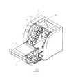
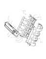
次にカートリッジ7の構成について図3乃至図5を用いて説明する。図3は現像剤tを収納したカートリッジ7の主断面、図4はその斜視図である。但し、図4は第二枠体4と第一枠体6とを分解した状態を図示している。図5はカートリッジ7を感光体ドラム1とは反対方向から見た斜視図である。即ち、図5はカートリッジ7を装置本体Aに装着する装着方向先端であって、枠体4・6の長手方向一端の斜視図である。[Process cartridge configuration]
Next, the configuration of the
図3に示すように、カートリッジ7は、ドラム形状の電子写真感光体すなわち電子写真感光体ドラム1と、帯電ローラ2およびクリーニングブレード60を備えた第一枠体6と、感光体ドラム1上の静電潜像を現像する現像ローラ40を有する第二枠体4とに分かれている。 As shown in FIG. 3, the
第一枠体6には、感光体ドラム1が軸受部材(カートリッジ位置決め部材)31を介して回転自在に取り付けてられている。感光体ドラム1の周面には、感光体ドラム1の表面を一様に帯電させるための帯電ローラ2、および感光体ドラム1上に残った現像剤を除去するためのクリーニングブレード60が配置されている。 The
クリーニングブレード60によって感光体ドラム1周面から除去された現像剤は、現像剤送り機構62によってドラムユニット枠体61の後方に設けられた廃現像剤室63に順次送られる。そして第二枠体4の他端に設けられたはす歯ギア46に駆動モータ(不図示)の駆動力を伝達する。即ち、はす歯ギア46は、カートリッジ7が装置本体Aに装着された際に、装置本体Aから現像ローラ42、現像剤供給ローラ43および搬送部材42を回転させるための駆動力の伝達を受ける。これにより、感光体ドラム1を画像形成動作に応じて回転駆動(反時計方向)させる。また、カートリッジ7は画像形成装置本体Aに対して、精度良く位置決めするために、感光体ドラム1の軸方向両端部に取り付けられた軸受部材31を介して、画像形成装置本体Aに設けられた側板106に位置決めされる。
The developer removed from the circumferential surface of the
第二枠体4は、感光体ドラム1と接触して回転する(矢印Y方向)現像ローラ40、および現像剤が収納された現像剤収納部41と現像容器45とを有する。現像ローラ40は、現像軸受47、48を介して回転自在に現像容器45に支持されている。また現像ローラ40の周面上には、現像ローラ40と接触して回転する(矢印Z方向)現像剤供給ローラ43と現像ブレード44がそれぞれ配置されている。さらに現像剤収納部41内には収納された現像剤を撹拌するとともに、現像剤を現像剤供給ローラ43に搬送するための現像剤搬送機構42が設けられている。 The
そして図4に示すように、第二枠体4は、第二枠体4の両端に取り付けられた現像軸受47、48にそれぞれ設けられた支持穴49を中心にして、ピン49aによって第二枠体4全体が感光体第一枠体6に対して回動自在に支持されている。 As shown in FIG. 4, the
カートリッジ7は、単体(装置本体Aに装着されていない)状態においては、支持軸49aを中心にして、回転モーメントにより現像ローラ40が感光体ドラム1の方向へ付勢されるよう、加圧バネ64によって第二枠体4が常に付勢されている。 When the
現像時、現像剤攪拌部材42によって、収納された現像剤が現像剤供給ローラ43へ搬送される。そして、回転する(矢印Z方向)現像剤供給ローラ43が、その現像剤を回転する(矢印Y方向)現像ローラ40との摺擦によって現像ローラ40に供給する。そして現像剤を現像ローラ40の周面に担持させる。現像ローラ40上に担持された現像剤は、現像ローラ40の回転に伴い現像ブレード44に至る。そして、現像ブレード44が現像剤に対して電荷を付与する。これによって、現像ローラ40の周面に所定の現像剤薄層を形成する。これによって、現像剤が感光体ドラム1と現像ローラ40とが接触した現像部に搬送される。現像部において、画像形成装置100が有する電源(不図示)から現像・供給電気接点92を介して現像ローラ40に印加した直流現像バイアスにより、現像剤は感光体ドラム1の表面に形成されている静電潜像に付着して潜像を現像する。 During development, the
現像に寄与せずに現像ローラ40の表面に残留した現像剤は、現像ローラ40の回転にともない現像器内に戻される。そして、現像剤供給ローラ43との摺擦部で現像ローラ40から剥離、回収される。回収された現像剤は、現像剤攪拌機構42により残りの現像剤
と撹拌混合される。The developer remaining on the surface of the developing
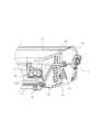
カートリッジ7の感光体ドラム1の軸線方向を長手方向とすると、カートリッジ7の長手方向側面には、前述の帯電ローラ2、現像ローラ40、現像剤供給ローラ43及び現像ブレード44にそれぞれに、本体電源(不図示)より高電圧を供給するための帯電電気接点91、現像・供給電気接点92、ブレード電気接点93が配置されている。ここで、帯電電気接点91は帯電ローラ2を支持する第一枠体6の長手方向(前記軸線方向)一端に配置されている。 Assuming that the axial direction of the
また、現像・供給電気接点92およびブレード電気接点93は、現像ローラ40、現像剤供給ローラ43および現像ブレード44を支持する第二枠体4の長手方向(前記軸線方向)一端に配置されている。即ち、各電気接点が、それぞれの枠体4・6の長手方向(前記軸線方向)同じ側側面4a,6aに配置されている。即ち、これら電気接点は同じ側側面4a,6aから側方へ向かって露出して設けられている。 The development / supply
これらの電気接点91,92,93は、カートリッジ7が装置本体Aに装着された際に、装置本体Aに設けられた、本体帯電電気接点111(111Y〜111K)、本体現像・供給電気接点112(112Y〜112K)、本体ブレード電気接点113(113Y〜113K)と接触して、カートリッジ7の各部品へ給電を行う。尚、電気接点91,92,93は各部品と電気的に接続している。また、本体電気接点111,112,113は電源(不図示)と電気的に接続している。 These
即ち、前記第一枠体6には、前記感光体ドラム1を帯電するための帯電ローラ2が設けられている。そして、前記第一枠体6の前記感光体ドラム軸線方向一端に設けられた第一枠体側面6aには、前記カートリッジ7が前記装置本体Aに装着された際に、前記装置本体Aから、前記帯電ローラ2に供給するための電圧を受ける帯電電気接点91が設けられている。 That is, the
また、前記第二枠体4には、前記現像部材としての現像ローラ40と、前記現像ローラ40の周面に付着する現像剤量を規制する現像ブレード44と、前記現像ローラ40の周面に現像剤を供給する現像剤供給ローラ43が設けられている。そして前記第二枠体4の前記電子写真感光体ドラム1の軸線方向一端に設けられた第二枠体側面4aには、前記カートリッジ7が前記画像形成装置本体Aに装着された際に、前記画像形成装置本体Aから、前記現像ブレード44に供給するための電圧を受けるブレード電気接点93が設けられている。また、第二枠体側面4aには、前記カートリッジ7が前記画像形成装置本体Aに装着された際に、前記画像形成装置本体Aから、前記現像ローラ40と前記現像剤供給ローラ43に供給するための電圧を受ける現像・供給電気接点92が設けられている。 The
このように構成することで、カートリッジの電気的接続部をカートリッジ7の一端側に集約できる。そのため、装置本体Aに設けられた電気接続部も集約できる。よって、装置本体Aに設けられた電気接続部を共通の電気基板に集約できる。 With this configuration, the electrical connection portion of the cartridge can be concentrated on one end side of the
[画像形成装置のプロセスカートリッジ支持構成]
次に、画像形成装置100に設けられた、カートリッジ7を支持するカートリッジ支持構成について、図6乃至図10を用いて説明する。図6は画像形成装置の開閉カバー11を開いた開口時の状態を表す断面図、図7はその斜視図、及び、図8はカートリッジ支持板の構成を示す斜視図である。また、図9はカートリッジ7を画像形成装置本体Aの装着位置に装着した際の位置決め構成を説明する説明図、図10は前記開閉カバー11を閉じて、カートリッジ7が装置本体Aに位置決めされた状態を示す説明図である。なお図9、図10は画像形成装置本体Aの一番上方に配置されたカートリッジ装着位置について説明
を行い、他のカートリッジ装着位置に関しては図示を省略する。しかしながら、各色のカートリッジの装着位置において同様の構成である。[Process cartridge support structure of image forming apparatus]
Next, a cartridge support configuration for supporting the
前記開閉カバー11は画像形成装置100の正面下方側に回転中心を有している。開閉カバー11に前述の中間転写体5が設けられている。そのため、開閉カバー11を開くと、操作者がカートリッジ7Y、7M、7C、7Kへのアクセスが可能となる。ここで、カートリッジ7Y、7M、7C、7Kを一体で保持するのはカートリッジ保持体101である。このカートリッジ保持体101の支点101a−bは、装置上方に設けられている。 The opening /
そして、リンク機構(不図示)により開閉カバー11と連結されている。これにより、開閉カバー11が開くことでカートリッジ保持体101は、ピボット点101a−bを中心にして回転移動する。従って、保持体101に保持されている各カートリッジ7は、所定の角度をもって支持され、移動する。本実施例では、このときの角度は約45度である。このように開閉カバー11が開くことで、カートリッジ7は装置本体Aに対する着脱が容易になる。 And it is connected with the opening-and-
本実施例において、カートリッジ保持体101は低コストを実現するため左右(101a、101b)で別体としたが、保持部材としては一体でも構わないし、別部材にて連結しても構わない。なお、左右別体となる場合でも、リンク部材によって連結している。従って、一体構成と同様の支持部材となる。 In this embodiment, the
また、図8に示すように前記保持体101bは、カートリッジ7に高電圧を供給するための電気接点として、前述した、本体帯電電気接点111、本体現像・供給電気接点112、本体現像ブレード電気接点113を有している。そこで、カートリッジ7が矢印方向に向かってカートリッジ保持体101に装着されると、カートリッジ7が有する、前述した帯電電気接点91、現像・供給電気接点92、現像ブレード電気接点93と接触する。尚、カートリッジ7の装置本体100に対する装着方向は、感光体ドラム1の長手方向(前記軸線方向)と交差する方向である。 Further, as shown in FIG. 8, the holding body 101b has the above-mentioned main body charging
以下、カートリッジ7をカートリッジ保持体101に装着し、開閉ドア11の閉動作を行う際のカートリッジの位置決め構成について説明する。 Hereinafter, the cartridge positioning structure when the
カートリッジ保持体101が画像形成時の位置に比べて約45度角度を有する位置まで外側へ移動した状態で、カートリッジ7は、ラフな操作で装置本体Aへ挿入される。 The
図9に示すように、挿入されたカートリッジ7は、カートリッジ保持体101の奥まで挿入された第1の装着位置において、カートリッジ規制部81が本体規制部101a−fと当接する。ここで、本体規制部101a−fは、装置本体100としてのカートリッジ保持体101に設けられている。 As shown in FIG. 9, in the inserted
次に、開閉ドア11を閉じると、カートリッジ保持体101は前述のリンク機構により連動して画像形成装置本体A内に移動する。そして、図10に示すような画像形成可能な第2の装着位置に移動する。第2の装着位置では、感光体ドラム1の両端部で第一枠体6から感光ドラム1軸線方向両側に突出した位置決め部(第一カートリッジ位置決め部・第二カートリッジ位置決め部)であるドラム軸受部材31が、画像形成装置本体Aに設けられた側板106に設けられた本体位置決め部(第一本体位置決め部・第二本体位置決め部)106aにそれぞれ係合する。そして軸受部材31が側板106の後方と下方の2つの面106a1、106a2に押し当てられる。 Next, when the open /
また、第2の装着位置に移動された際に、カートリッジ規制部81が本体規制部101
a−fと当接する。Further, when the
af contacts.
即ち、カートリッジ7は、前記カートリッジ7が前記画像形成装置本体Aに装着された際に、前記カートリッジ7を前記画像形成装置本体Aに位置決めするために、前記第一枠体6の前記軸線方向一端側に設けられ、前記画像形成装置本体Aに設けられた第一本体位置決め部106aと係合する第一カートリッジ位置決め部31を有する。さらに、カートリッジ7は、前記カートリッジ7が前記画像形成装置本体100に装着された際に、前記カートリッジを前記画像形成装置本体Aに位置決めするために、前記第一枠体6の前記感光体ドラム軸線方向他端側に設けられ、前記画像形成装置本体Aに設けられた第二本体位置決め部106aと係合する第二カートリッジ位置決め部31を有する。さらに、カートリッジ7は、駆動力受け部30が前記画像形成装置本体Aから駆動力の伝達を受ける際に、前記第一カートリッジ位置決め部31と前記第二カートリッジ位置決め部31とを中心にして、前記カートリッジ7が回転しようとするのを、前記画像形成装置本体Aに設けた本体規制部101a−fと接触して規制する、前記第一枠体6に設けられたカートリッジ規制部81を有する。 That is, the
次にカートリッジ7が画像形成装置本体100から駆動力の伝達を受ける際の説明をする。 Next, a description will be given of when the
カートリッジ7には感光体ドラム1の軸線方向一端側に感光体ドラム1の支持軸と結合された駆動力受け部(駆動カップリング)30が設けられている。装置本体Aの駆動力伝達手段(不図示)と駆動力受け部30が係合して装置本体Aから駆動力を受けると、感光体ドラム1は時計回り方向(図10)に回転する。駆動力を受けると第一枠体6も第1、第2カートリッジの位置決め部であるドラム軸受部材31を結ぶ軸線中心に矢印方向にモーメントを受ける。このとき、第3の位置決め部であるカートリッジ規制部81が本体規制部101a−fと当接する。そして、駆動力によるモーメントを受け止め、駆動時の回転方向の姿勢を決めている。即ち、カートリッジ7は感光体ドラム1を中心にして、精度良く装置本体100に位置決めされる。 The
[撹拌部材の構成と光透過式現像剤残量検知]
次に、光透過式現像剤残量検知について図11および図12を用いて説明する。図11は、本実施の形態に係る光透過式の現像剤残量検知手段を備えたカートリッジ7において検知光が受光部まで届いている状態を示す断面図である。図12は、検知光が受光部まで届いていない状態を示す断面図である。[Structure of stirring member and detection of light-transmitting developer remaining amount]
Next, light transmission type developer remaining amount detection will be described with reference to FIGS. 11 and 12. FIG. FIG. 11 is a cross-sectional view showing a state in which the detection light reaches the light receiving portion in the
図11に示すように、現像剤収納部41内には、現像剤撹拌部材42が設けられている。そして、X方向に回転することで供給ローラ43に現像剤を搬送している。撹拌部材42は軸部材42a、現像剤撹拌を行うための可撓性シート部材42bを有する。 As shown in FIG. 11, a
撹拌部材42への駆動力の伝達は現像剤収納部41の側面を貫通して挿入される駆動ギア(不図示)によって行われる。 The driving force is transmitted to the agitating
一方、現像剤収納部41は、現像剤残量検知用光透過窓と光導入部を一体とした入射側第一光ガイド51および第二光ガイド52を有している。そして、現像剤収納部41は、カートリッジ7の長手方向(感光体ドラム1の軸線方向)において、前述した電気接点配置側面4a,6aと同一端部寄り(図5)に有している。第一光ガイド51は、画像形成装置本体Aに設けられた発光部(LED)53から発光された現像剤残量検知光Lを現像剤収納部41内部へ導くものである。また、現像剤収納部41内を通過した検知光Lは、第二光ガイド52を介して同じく画像形成装置本体Aに設けられた受光部(フォトトランジスタ)54へ導かれる。前記シート部材42bは、その回転に伴い、検知光Lを遮光す
るとともに第一光ガイドの現像剤収納部41内光透過面51bと第二光ガイドの現像剤収納部41内光透過面52bの清掃を行う。On the other hand, the
尚、本実施例においては、第二光ガイドの出射面52aは第一光ガイドの入射面51aよりも、カートリッジ7の画像形成装置本体Aへの装着方向(図11、12において左方向)先端へ突出している。 In the present embodiment, the
図11は、シート部材42bが前記光透過面51bを清掃した直後の状態である。図11において、現像剤残量が比較的少ない状態である。そのため、検知光Lは、現像剤収納部41内部を透過し、第二光ガイド52を介して装置本体A内の受光部54で検知された状態である。一方、図12は、シート部材42bが前記光透過面51bを清掃する直前の状態である。検知光Lは、現像剤および撹拌部材42の存在により現像剤収納部41の内部で遮られる。そして、検知光Lは、第二光ガイドに届かず、画像形成装置本体100内の受光部54で検知されない状態である。 FIG. 11 shows a state immediately after the
以上に示した構成において、撹拌部材42の1回転あたりに現像剤収納部41の内部を透過して、前記受光部54で受光される検知光Lの受光時間を装置本体Aが有する制御部(不図示)において、あらかじめ設定された手順で処理する。これにより、現像剤収納部41内の現像剤についておよそ有効現像剤残量の25〜0%の範囲で現像剤残量を推測することができる。 In the configuration shown above, the apparatus main body A has a light receiving time of the detection light L that passes through the inside of the
即ち、カートリッジ7は、前記第二枠体4の前記感光体ドラム1の軸線方向一端側、および前記カートリッジ7の装着方向先端側に設けられている。そして、カートリッジ7は、前記カートリッジ7が前記装置本体Aに装着された際に前記発光部53と対向する第一光ガイド51の入射部51aと、前記第二枠体4の前記一端側、および前記装着方向先端側に設けられ、前記カートリッジ7が前記装置本体Aに装着された際に前記受光部54と対向する第二光ガイド52の出射部52aを有する。 That is, the
そして、前記カートリッジ7が前記装置本体Aに装着された際に、前記第一枠体6が上方に位置し、前記第二枠体4が下方に位置し、前記第一光ガイド51は前記現像剤収納部41の下方に位置し、前記発光部53から発光された検知光Lを前記入射部51aを介して前記現像剤収納部41内へ導く。そして、前記第二光ガイド52は前記現像剤収納部41の上方に位置し、前記現像剤収納部41内を通過した光Lを前記出射部52aを介して前記受光部54へ導く。ここで、前記一端側とは、前記軸線方向において、前記第二枠体の中央よりも一端寄りを意味する。 When the
このように構成することで、感光体ドラム1に対向する位置に発光部53を配置せずにすむ。そのため、感光体ドラム1が検知光Lによって露光されることを防止できる。よって、画像品質を向上させることができる。 With this configuration, it is not necessary to arrange the
そして、前記第二枠体4の前記感光体ドラム1の軸線方向端部から見て、前記第二光ガイド52は前記第一光ガイド51よりも前記カートリッジ7の装着方向へ突出しており、前記出射部52aは前記入射部51aよりも前記カートリッジ7の装着方向先端側に位置している。 When viewed from the axial end of the
[プロセスカートリッジの記憶手段の構成]
次に図1、及び図13を用いて、カートリッジ7に設けられた記憶手段の構成と画像形成装置本体Aとの通信について説明する。図13は本実施の形態に係る記憶手段を有するカートリッジの背面図である。[Configuration of process cartridge storage means]
Next, the configuration of the storage unit provided in the
記憶手段55(以下メモリユニット)はカートリッジ7の挿入方向先端の長手方向端部に設けられている。メモリユニット55は絶縁性の基板55a上にメモリ55b、及び、カートリッジ電気接点としての第一・第二電気接点55d1・55d2が導電領域55c1・55c2内に配置されている。導電領域55c1・55c2はメモリ55bを挟んで左右に一つずつ配置されている。 The storage means 55 (hereinafter referred to as memory unit) is provided at the longitudinal end of the
更に、カートリッジ7は、前記第一枠体6の前記感光体ドラム軸線方向一端側、および前記カートリッジ7の装着方向先端に設けられ、前記カートリッジ7が前記画像形成装置本体Aに装着された際に、前記画像形成装置本体Aに設けられた本体電気接点56aと接触して、前記メモリ55bに記憶されている情報を前記画像形成装置本体Aに伝えるカートリッジ電気接点55dを有する。 Further, the
そして前記メモリ55b、前記カートリッジ電気接点55d1としての第一電気接点を有する第一導電領域55c1と、前記カートリッジ電気接点としての第二電気接点55d2を有する第二導電領域55c2が同一の基板55aに設けられている。そして前記基板55aの前記軸線方向に沿って内側から外側へ、前記第一導電領域55c1、前記メモリ55b、前記第二導電領域55c2がこの順番で配置されている。そして、前記第二枠体4の前記感光体ドラム1の軸線方向において外側に位置する、前記入射部51aの外側端部と前記出射部52aの外側端部とを結んだ直線S1(図13)が少なくとも前記基板55aを横切る。尚、本実施例では、直線S1が、ドラム1の軸線方向において、内側に位置する第一導電領域55cを横切っている。 The
このように構成することで、第一・第二光ガイド間のデッドスペースを有効に利用できる。特に、感光体ドラム1の軸線方向についての小型化を実現できる。 With this configuration, the dead space between the first and second light guides can be used effectively. In particular, downsizing of the
尚、図13に示す通り、本実施例では、前記第一電気接点55d1は前記第一導電領域55c1に二箇所、前記第二電気接点55d2は前記第二導電領域55c2に二箇所設けられている。このように構成することで、電気接続の信頼性を向上させることができる。画像形成装置本体Aにはコントローラ(不図示)に接続された通信手段である通信ユニット56が設けられている。カートリッジ7が装置本体Aに装着されると、メモリユニット55の第一・第二導電領域55c1・55c2内の電気接点55d1・55d2と通信ユニットの通信用接点部(本体電気接点)56aが接触し、メモリユニット55のメモリ55bとコントローラが通信可能となる。そしてメモリ55bの情報の読み取り、書き込みが可能となる。 As shown in FIG. 13, in this embodiment, the first electrical contact 55d1 is provided in two locations in the first conductive region 55c1, and the second electrical contact 55d2 is provided in two locations in the second conductive region 55c2. . With this configuration, the reliability of electrical connection can be improved. The image forming apparatus main body A is provided with a
メモリ55bに格納される情報は、例えば、カートリッジ7が有する電子写真感光体ドラム1や現像剤tの種類、ロット番号、カートリッジ7が使用された履歴、画像形成回数など、カートリッジ7の状態を示す種々のパラメータの内一つ以上のパラメータをいう。 The information stored in the
あるいは、例えば、前記カートリッジ電気接点55d1・55d2を介して前記装置本体Aから伝達される、前記現像剤収納部41内に収納されている現像剤量に関する情報である。本実施例においては少なくとも、前述した現像剤残量検知手段によって得られた現像剤残量に関する情報が含まれる。このように、メモリ55bが現像剤の残量に関する情報を記憶することで、例えば使用中にカートリッジ7を別の装置100に移動した場合でも適切な寿命管理ができる。 Alternatively, for example, it is information regarding the amount of developer stored in the
メモリユニット55は両面テープ、接着剤、熱カシメ、超音波溶着、スナップフィットなどの方法で第一枠体6に取り付けられている。また、カートリッジ7は第一枠体に設けられた第一・第二カートリッジ位置決め部(軸受部材)31で装置本体Aに位置決めされる。そのため、第一枠体6に設けられたメモリユニット55も装置本体100に精度良く
位置決めされる。よって、ユニット55は装置本体Aに設けられた通信ユニット56と精度良く位置決めすることができる。The
前記通信ユニット56は、4個の導電性の本体電気接点部56aを有している。そして、2個ずつがセットとなり、対向するメモリユニット55の二つの導電領域55c1・55c2に接触する。 The
このように、導電領域55c1・55c2それぞれ二箇所のカートリッジ電気接点を設けることで、通信の信頼性を向上させている。即ち、第一電気接点55d1、第二電気接点55d2が各々2箇所設けられている。なお、第一・第二電気接点55d1・55d2はカートリッジ7を装置本体Aに装着した際に、前記本体電気接点56aと導電領域55c(55c1・55c2)が摺擦して発生する摺擦痕を模式的に表したものである。 Thus, the reliability of communication is improved by providing two cartridge electrical contacts for each of the conductive regions 55c1 and 55c2. That is, two first electrical contacts 55d1 and second electrical contacts 55d2 are provided. The first and second electrical contacts 55d1 and 55d2 are rubbed when the
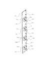
次に、図14、図15を用いて、カートリッジ7を装置本体Aに装着した状態を示す。図14は本実施の形態に係るカラー画像形成装置100とカートリッジ7の構成を示す概略断面図、図15は装置本体Aに設けられた発光部53、受光部54及び通信ユニット(本体電気接点)56aを搭載した絶縁性の基板57の斜視図である。Next, a state in which the
カートリッジ7は感光体ドラム1を中間転写体5側にして、装置本体Aに対して、4個鉛直方向に並べて装着される。即ち、互いに異なった色の現像剤を有するカートリッジ7Y、7M、7C、7Kを取り外し可能に装着するための、垂直方向に並んで配置された複数個のカートリッジ装着部7tを有する。また図1に示すように、第一光ガイド51及び第二光ガイド52は装着方向先端側にその入射部51a及び出射部52aを有する。前記入射面51a・出射面52aは、現像剤収納部41の高さ分離れた位置に互いに平行に配置されている。したがって、現像剤収納部41の高さ分の領域がデッドスペースとなる。 Four
そこで、本実施の形態に係るカートリッジ7では、この領域にプリンタ100と通信を行うメモリユニット55を配置している。 Therefore, in the
具体的には、メモリユニット55は、図16に示すように、本実施の形態におけるカートリッジ7をプリンタ100本体に装着した状態で、入射部51aを含む水平面A1と出射部52aを含む水平面A2との間の領域に配置されている。そして、図17に示すように、入射部51aと出射部52aを含み感光体ドラム1の回転軸Rに対して直交する鉛直面A3にメモリユニット55の一部が含まれるように配置されている。 Specifically, as shown in FIG. 16, the
そのため、入射部51aとメモリユニット55と出射部52aとが鉛直方向に直列となるようにメモリユニット55を配置することになる。従って、第一のライトガイド51、第二のライトガイド52及びメモリユニット55をコンパクトにカートリッジ7に設けることができる。特に、感光体ドラム1の軸方向の省スペース化が可能となり、カートリッジ7を小型にできる。しいては、カートリッジ7を着脱可能なプリンタ100を小型にできる。 Therefore, the
また、プリンタ側に設けられたメモリユニット55と、第一のライトガイド51、第二のライトガイド52が互いに近接した領域に配置され、かつ、通信ユニット56は、図16に示すように、本実施の形態におけるカートリッジ7をプリンタ100に装着した状態で、LED53を含む水平面A1とフォトトランジスタ54を含む水平面A2との間の領域に配置されている。 In addition, the
そのため、LED53、フォトトランジスタ54、通信ユニット56を同一の基板上に配置することができる。更には、それらの制御手段を同一の基板上に配置することができ
る。そのため複数の基板に部品や制御手段を分散する必要がなくなり、部品数の低減及び小型化が図られる。Therefore, the
また、図14に示すように、入射部51aと、出射部52aと、メモリユニット55とを鉛直方向に直列になるようにメモリユニット55を配置したカートリッジ7は、鉛直方向に複数個並べて装着したカラーのプリンタ100に好適に用いることができる。 Further, as shown in FIG. 14, a plurality of
すなわち、第一のライトガイド51、第二のライトガイド52及びメモリユニット55の対向面に配置される、現像剤残量検知を行うためのLED53、フォトトランジスタ54及び通信ユニット56を一カ所に集約して配置することが可能である。 That is, the
したがって、LED53、フォトトランジスタ54及び通信ユニット56は、図15に示すように、コンパクトな一枚の長方形の基板57上に集約して配置することができる。これにより、無駄な電気配線もなく、部品がコンパクトに集約され、複数のカートリッジ7を有するプリンタ100においては更に小型化に寄与する。 Therefore, the
前述した通り、本実施例においては、この領域にメモリユニット55を配置する。具体的には、図1及び図13に示すように、入射面51aと出射部52aは、カートリッジ7の挿入方向先端側で長手方向(ドラム1の軸線方向)同一部位に配置される。これに対してメモリユニット55は、前記長手方向において、入射部51aと出射面52aの外側端面を結んだ直線S1を横切るように配置する。さらに詳細に述べると、本実施例においては、前記直線S1は、メモリユニット55の導電領域55cを横切るように構成されている。 As described above, in this embodiment, the
従って、感光体ドラム1上に潜像形成を行う画像光との干渉を避けるようにして、前記長手方向において、前記入射部51a、出射部52aとメモリユニット55をずらして配置した場合と比較して、前記長手方向における第一枠体6の省スペース化が可能となる。よってカートリッジ7の全体の小型化が可能となる。 Therefore, as compared with the case where the
また、前記入射部51a、出射部52a及びメモリユニット55を鉛直方向に配置し、かつ近接して配置したので、このような構成のカートリッジ7を、装着して使用する画像形成装置100では、それらに対向する現像剤残量検知を行うための発光部(LED)53、受光部(フォトトランジスタ)54および通信ユニット56を近接して配置することができる。 Further, since the
このため、発光部53(53Y・53M・53C・53K),受光部54(54Y・54M・54C・54K)及び通信ユニット56を同一の基板57に配置することができる。更には、それらの制御手段を同一の基板57に配置することができる。従って複数の基板に部品や制御手段を分散する必要が無くなる。よって、部品点数の削減と装置本体Aの小型化が可能となる。 For this reason, the light emission part 53 (53Y * 53M * 53C * 53K), the light-receiving part 54 (54Y * 54M * 54C * 54K), and the
更に図14に示すように、前記入射部51a、出射部52a及びメモリユニット55を鉛直方向に近接して配置しカートリッジ7を、鉛直方向に複数個並べて装着するカラー画像形成装置100では、発光部53、受光部54および通信ユニット56を、一枚の鉛直方向に長い長方形のセンサ基板57に配置できる(図15)。 Further, as shown in FIG. 14, in the color
従って、各部品を複数の基板に部品や制御手段を分散する必要が無くなる。よって、無駄な電気配線もなく、部品をコンパクトに集約して配置することができる。そこで、画像形成装置において、100の部品点数の削減、小型化が可能となる。 Therefore, it is not necessary to distribute the components and control means on a plurality of substrates. Therefore, there is no useless electrical wiring, and the components can be arranged in a compact manner. Therefore, in the image forming apparatus, the number of 100 parts can be reduced and the size can be reduced.
なお、本実施例においては、前記線S1は、メモリユニット55の導電領域55cを横切るように構成した。しかしながら、線S1がメモリユニット55のどの領域を横切るように配置されていても、同様の効果を得ることが可能である。 In this embodiment, the line S1 is configured to cross the conductive region 55c of the
また、図5に示すように、本実施例においてはカートリッジ7の長手方向(ドラム1の軸線方向)において、前述した各電気接点91,92,93は、前記第一・第二光ガイド51,52およびメモリユニット55と同一端部側の側面に配置されている。そのため、装置本体Aとカートリッジ7の電気的接続部を集約して配置することができる。従って、装置本体Aに設けた電源(不図示)と各電気基板との配線も短縮することが可能となる。 Further, as shown in FIG. 5, in the present embodiment, in the longitudinal direction of the cartridge 7 (the axial direction of the drum 1), the above-described
1 感光体ドラム
2 帯電ローラ(帯電部材)
3 スキャナユニット
4 第二枠体
5 中間転写体
6 第一枠体
7 プロセスカートリッジ
8 定着器
9 ポリゴンミラー
12 一次転写ローラ
13 二次転写ローラ
14 駆動ローラ
15 二次転写対向ローラ
16 テンションローラ
17 給送カセット
18 給送ローラ
19 分離パッド
21 レジストローラ対
22 搬送ベルト
23 フィルムガイドユニット
24 加圧ローラ
25 排出ローラ対
26 排出トレイ
30 駆動力受け部
31 軸受部材
40 現像ローラ(現像部材)
41 現像剤収納部
42 搬送部材
43 供給ローラ
44 現像ブレード
45 現像枠体
46 はす歯ギア
47 現像軸受
49 支持穴
49a 支持軸
51 第一光ガイド
51a 入射部
51b 光透過面
51c 透過部
52 第二光ガイド
52a 出射部
52b 光透過面
52c 透過部
53 発光部
54 受光部
55 メモリユニット
55a 基板
55b メモリ
55c 導電領域
55d 電気接点
56 通信ユニット
56a 通信用接点部(本体電気接点)
57 基板
60 クリーニングブレード
60 クリーニング装置
61 感光体ユニット枠体
62 現像剤送り機構
63 収容室
64 加圧バネ
81 カートリッジ回転規制部
91 帯電電気接点
92 現像・供給電気接点
93 現像ブレード電気接点
100 電子写真画像形成装置(プリンタ)
100A カートリッジ装着部
101 カートリッジ保持体
101a−f 本体側回転規制部
106 側板
106a 本体側位置決め部
111 本体帯電電気接点
112 本体現像・供給電気接点
113 本体現像ブレード電気接点
A 電子写真画像形成装置本体
L 検知光
P 記録媒体
T1 一次転写部
T2 二次転写部
t 現像剤1
3
DESCRIPTION OF
57
DESCRIPTION OF
Claims (11)
Translated fromJapanese電子写真感光体ドラムと、
前記電子写真感光体ドラムに形成された静電潜像を現像する現像部材と、
前記静電潜像を現像するために前記現像部材で用いられる現像剤を収納する現像剤収納容部を有するカートリッジ枠体と、
前記カートリッジ枠体の前記電子写真感光体ドラムの軸線方向一端側、および前記プロセスカートリッジが前記装置本体へ装着される装着方向先端側に設けられた第一光ガイドであって、前記プロセスカートリッジが前記装置本体に装着された際に前記発光部と対向して、前記検知光を入射させる入射部を有し、前記現像剤収納容器内の現像剤収納空間を横切るように前記検知光をガイドする第一光ガイドと、
前記カートリッジ枠体の前記一端側、および前記装着方向先端側に設けられた第二光ガイドであって、前記プロセスカートリッジが前記装置本体に装着された際に前記受光部と対向して、前記現像剤収納空間を通過した前記検知光を前記受光部へ出射させる出射部を有する第二光ガイドと、
前記カートリッジ枠体の前記一端側、および前記装着方向先端側に設けられた、前記装置本体と通信可能なメモリ部材であって、前記プロセスカートリッジが前記装置本体に装着された際の鉛直方向において、前記入射部を通る水平面と前記出射部を通る水平面との間に設けられた、前記プロセスカートリッジが前記装置本体に装着された際に前記本体電気接点と電気的に接続するカートリッジ電気接点を有するメモリ部材と、
を有し、
前記メモリ部材の少なくとも一部は、前記入射部と前記出射部とを結んだ直線を横切ることを特徴とするプロセスカートリッジ。A light emitting unit, a light receiving unit that receives the detection light was originatingSerare from the light emitting portion, and the main body electrical contact,said light emitting portion, the light receiving portion, and a body base having integrally the body electrical contact, A process cartridgethat can be attached to and detached froman apparatus main body of an electrophotographic image forming apparatus having:
An electrophotographic photosensitive drum;
A developing member for developing the electrostatic latent image formed on the electrophotographic photosensitive drum;
A cartridge frame having a developer accommodating portion for accommodating a developer used in the developing member for developing the electrostatic latent image;
Axial end sideof said electrophotographic photosensitive drum of the cartridge frame, and said a first light guide the process cartridgeis provided in the mounting direction front end side thatwill be mounted to the main assembly of the apparatus, said process cartridge is pre the opposite to the light emitting portion when attachedtoKiSo Okimoto bodyhas an entrance portion which Ruis incident the detection light, the developer accommodating said detection light across the developer storage space in the container A first light guide to guide,
Wherein one end of said cartridge frame, and said a second light guide provided in the mounting direction front end side, the opposite to the light receiving portionwhen said process cartridge is mounted to the frontKiSo Okimotobody, a second light guide having an emitting portion of the detecting light having passed through the developer accommodating space Ruis emitted to the light receiving unit,
A memory member provided on the one end side of the cartridge frame and on the front end side in the mounting direction and capable of communicating with the apparatus main body, in the vertical direction when the process cartridge is mounted on the apparatus main body, memory havinga main body electrical contact electrically cartridge electrical contactsthat connect when provided, said process cartridge is mounted to the main assembly of the apparatusbetween a horizontal plane passing through the horizontal plane and the emitting portion through said entrance portion A member,
I have a,
At least a part of the memory member crosses a straight line connecting the incident portion and the emission portion .
前記第一光ガイド、及び、前記第二光ガイドは、前記第二枠体に設けられていることを特徴とする請求項1又は2に記載のプロセスカートリッジ。The cartridge frame includes a first frame that supports the electrophotographic photosensitive drum, the developing member, and a second frame that supports the developer container, and the memory member Provided in the first frame,
The process cartridge according to claim 1, wherein the first light guide and the second light guide are provided on the second frame.
前記プロセスカートリッジが前記装置本体に装着された際に、前記装置本体から駆動力の伝達を受ける駆動力受け部と、A driving force receiving portion for receiving a driving force from the apparatus main body when the process cartridge is mounted on the apparatus main body;
前記プロセスカートリッジが前記装置本体に装着された際に、前記プロセスカートリッジを前記装置本体に位置決めするために、前記第一枠体の前記一端側に設けられ、前記装置本体に設けられた第一本体位置決め部と係合する第一カートリッジ位置決め部と、A first main body provided on the one end side of the first frame and positioned on the apparatus main body for positioning the process cartridge on the apparatus main body when the process cartridge is mounted on the apparatus main body. A first cartridge positioning portion that engages with the positioning portion;
前記プロセスカートリッジが前記装置本体に装着された際に、前記プロセスカートリッジを前記装置本体に位置決めするために、前記第一枠体の前記電子写真感光体ドラムの軸線方向他端側に設けられ、前記装置本体に設けられた第二本体位置決め部と係合する第二カートリッジ位置決め部と、When the process cartridge is mounted on the apparatus main body, the first cartridge is provided on the other end side in the axial direction of the electrophotographic photosensitive drum in order to position the process cartridge on the apparatus main body. A second cartridge positioning portion that engages with a second main body positioning portion provided in the apparatus main body;
前記駆動力受け部が前記装置本体から駆動力の伝達を受ける際に、前記第一カートリッジ位置決め部と前記第二カートリッジ位置決め部とを中心にして、前記プロセスカートリッジが回転しようとするのを、前記装置本体に設けられた本体規制部と接触して規制するカートリッジ規制部と、The process cartridge is about to rotate around the first cartridge positioning portion and the second cartridge positioning portion when the driving force receiving portion receives the driving force from the apparatus main body. A cartridge restricting portion that contacts and restricts a main body restricting portion provided in the apparatus main body;
を有することを特徴とする請求項3に記載のプロセスカートリッジ。The process cartridge according to claim 3, further comprising:
(i)発光部と、
(ii)前記発光部から発せられた検知光を受光する受光部と、
(iii)本体電気接点と、
(iv)前記発光部、前記受光部、及び、前記本体電気接点を一体的に備えた本体基体と、
(v)電子写真感光体ドラムと、前記電子写真感光体ドラムに形成された静電潜像を現像す
る現像部材と、前記静電潜像を現像するために前記現像部材で用いられる現像剤を収納する現像剤収納容部を有するカートリッジ枠体と、前記カートリッジ枠体の前記電子写真感光体ドラムの軸線方向一端側、および前記プロセスカートリッジが前記電子写真画像形成装置の装置本体へ装着される装着方向先端側に設けられた第一光ガイドであって、前記プ
ロセスカートリッジが前記装置本体に装着された際に前記発光部と対向して、前記検知光を入射させる入射部を有し、前記現像剤収納容器内の現像剤収納空間を横切るように前記検知光をガイドする第一光ガイドと、前記カートリッジ枠体の前記一端側、および前記装着方向先端側に設けられた第二光ガイドであって、前記プロセスカートリッジが前記装置本体に装着された際に前記受光部と対向して、前記現像剤収納空間を通過した前記検知光を前記受光部へ出射させる出射部を有する第二光ガイドと、前記カートリッジ枠体の前記一端側、および前記装着方向先端側に設けられた、前記装置本体と通信可能なメモリ部材であって、前記プロセスカートリッジが前記装置本体に装着された際の鉛直方向において、前記入射部を通る水平面と前記出射部を通る水平面との間に設けられた、前記プロセスカートリッジが前記装置本体に装着された際に前記本体電気接点と電気的に接続するカートリッジ電気接点を有するメモリ部材と、を有し、前記メモリ部材の少なくとも一部は、前記入射部と前記出射部とを結んだ直線を横切ることを特徴とするプロセスカートリッジを取り外し可能に装着する装着手段と、
(vi)前記記録媒体を搬送するための搬送手段と、
を有することを特徴とする電子写真画像形成装置。In an electrophotographic image forming apparatus for detaching a process cartridge and forming an image on a recording medium,
(i) a light emitting unit;
(ii) a light receiving unit that receives the detection light was originatingSerare from the light emitting portion,
(iii) the body electrical contacts;
(iv)a main body base body integrally including the light emitting section, the light receiving section, and the main body electrical contacts;
(v) an electrophotographic photosensitive drum, a developing member that develops the electrostatic latent image formed on the electrophotographic photosensitive drum, and a developer that is used in the developing member to develop the electrostatic latent image. a cartridge frame having a developer accommodating capacity portion for housing, mounting the axial direction one end sideof said electrophotographic photosensitive drum of the cartridge frame, and said process cartridgeis Ruis mounted into the apparatus main assemblyof theelectrophotographic image forming apparatus a first light guide provided on the forward end side, the opposite to the light emitting portionwhen said process cartridge is mounted to the frontKiSo Okimoto bodyhas an entrance portion which Ruis incident the detection light A first light guide that guides the detection light so as to cross the developer storage space in the developer storage container, and a second light guide provided on the one end side of the cartridge frame and on the front end side in the mounting direction. A guide, the opposite to the light receiving portionwhen said process cartridge is mounted to the frontKiSo Okimotobody, the emitting portion of the detecting light having passed through the developer accommodating space Ruis emitted to the light receiving portion A memory member provided on the one end side of the cartridge frame and on the front end side in the mounting direction and capable of communicating with the apparatus main body, wherein the process cartridge is mounted on the apparatus main body. in the vertical direction in the said horizontal plane passing through the incident portion and provided betweenthe horizontal plane passing through the exitportion, the main body electrical contact electrically connected when the process cartridge is mounted to the main assemblypossess a memory member, a having a cartridge electrical contacttothe at least a portion of the memory member, characterized in that cross the straight line connecting the said entrance portion and the exit portion A mounting means capable mounted remove the process cartridge,
(vi ) transport means for transporting the recording medium;
An electrophotographic image forming apparatus comprising:
更に、前記カラー電子写真画像形成装置は、複数個の前記発光部、複数個の前記受光部、及び、複数個の前記本体電気接点を一体的に有する本体基体を有することを特徴とする請求項9に記載の電子写真画像形成装置。
The electrophotographic image forming apparatus is a color electrophotographic image forming apparatus in which a plurality of process cartridges can be mounted,
The color electrophotographic image forming apparatus further includes a main body base body integrally including a plurality of light emitting sections, a plurality of light receiving sections, and a plurality of main body electrical contacts. The electrophotographic image forming apparatus according to 9.
Priority Applications (8)
| Application Number | Priority Date | Filing Date | Title |
|---|---|---|---|
| JP2004161219AJP4378221B2 (en) | 2003-10-08 | 2004-05-31 | Process cartridge and electrophotographic image forming apparatus |
| US10/878,610US7162174B2 (en) | 2003-10-08 | 2004-06-29 | Process cartridge having light guides and memory member, and electrophotographic image forming apparatus to which such cartridge is mountable |
| KR1020040049339AKR100731216B1 (en) | 2003-10-08 | 2004-06-29 | Process cartridge and electrophotographic image forming apparatus |
| DE602004016931TDE602004016931D1 (en) | 2003-10-08 | 2004-06-30 | Process Cartridge and Electrophotographic Image Forming Apparatus |
| CNB2004100628924ACN100367133C (en) | 2003-10-08 | 2004-06-30 | Process cartridge and electrophotographic image forming apparatus |
| EP07118707AEP1881378A1 (en) | 2003-10-08 | 2004-06-30 | Process cartridge and electrophotographic image forming apparatus |
| EP04015342AEP1522905B1 (en) | 2003-10-08 | 2004-06-30 | Process cartridge and electrophotographic image forming apparatus |
| US11/566,878US7346293B2 (en) | 2003-10-08 | 2006-12-05 | Process cartridge having light guides and memory member, and electrophotographic image forming apparatus to which such cartridge is mountable |
Applications Claiming Priority (3)
| Application Number | Priority Date | Filing Date | Title |
|---|---|---|---|
| JP2003349466 | 2003-10-08 | ||
| JP2003398939 | 2003-11-28 | ||
| JP2004161219AJP4378221B2 (en) | 2003-10-08 | 2004-05-31 | Process cartridge and electrophotographic image forming apparatus |
Publications (2)
| Publication Number | Publication Date |
|---|---|
| JP2005181968A JP2005181968A (en) | 2005-07-07 |
| JP4378221B2true JP4378221B2 (en) | 2009-12-02 |
Family
ID=34317258
Family Applications (1)
| Application Number | Title | Priority Date | Filing Date |
|---|---|---|---|
| JP2004161219AExpired - Fee RelatedJP4378221B2 (en) | 2003-10-08 | 2004-05-31 | Process cartridge and electrophotographic image forming apparatus |
Country Status (6)
| Country | Link |
|---|---|
| US (2) | US7162174B2 (en) |
| EP (2) | EP1522905B1 (en) |
| JP (1) | JP4378221B2 (en) |
| KR (1) | KR100731216B1 (en) |
| CN (1) | CN100367133C (en) |
| DE (1) | DE602004016931D1 (en) |
Families Citing this family (58)
| Publication number | Priority date | Publication date | Assignee | Title |
|---|---|---|---|---|
| US7448734B2 (en)* | 2004-01-21 | 2008-11-11 | Silverbrook Research Pty Ltd | Inkjet printer cartridge with pagewidth printhead |
| JP3970279B2 (en)* | 2004-07-30 | 2007-09-05 | キヤノン株式会社 | Process cartridge and electrophotographic image forming apparatus |
| US7664434B2 (en)* | 2004-12-28 | 2010-02-16 | Canon Kabushiki Kaisha | Charging member, process cartridge and electrophotographic apparatus |
| JP4349352B2 (en)* | 2005-09-26 | 2009-10-21 | ブラザー工業株式会社 | Image forming apparatus, process unit, and developing cartridge |
| JP4630166B2 (en)* | 2005-09-27 | 2011-02-09 | 株式会社沖データ | Developer accommodating device, developing device, and image forming apparatus |
| JP4280770B2 (en) | 2006-01-11 | 2009-06-17 | キヤノン株式会社 | Process cartridge and electrophotographic image forming apparatus |
| JP2007219294A (en)* | 2006-02-17 | 2007-08-30 | Brother Ind Ltd | Image forming apparatus and developer cartridge |
| JP4667444B2 (en) | 2006-12-13 | 2011-04-13 | キヤノン株式会社 | Electrophotographic image forming apparatus |
| US7856192B2 (en)* | 2006-12-28 | 2010-12-21 | Canon Kabushiki Kaisha | Process cartridge and electrophotographic image forming apparatus |
| JP5084257B2 (en)* | 2006-12-28 | 2012-11-28 | キヤノン株式会社 | Process cartridge and image forming apparatus using the same |
| JP4280772B2 (en) | 2006-12-28 | 2009-06-17 | キヤノン株式会社 | Process cartridge and electrophotographic image forming apparatus |
| JP4095649B1 (en) | 2006-12-28 | 2008-06-04 | キヤノン株式会社 | Electrophotographic image forming apparatus, process cartridge, and moving member |
| JP4985029B2 (en)* | 2007-03-29 | 2012-07-25 | ブラザー工業株式会社 | Image forming apparatus and process cartridge |
| JP5282375B2 (en)* | 2007-06-25 | 2013-09-04 | ブラザー工業株式会社 | Toner cartridge and developing device |
| JP4458377B2 (en) | 2007-06-29 | 2010-04-28 | キヤノン株式会社 | Process cartridge and electrophotographic image forming apparatus |
| JP4458378B2 (en) | 2007-06-29 | 2010-04-28 | キヤノン株式会社 | Process cartridge and electrophotographic image forming apparatus |
| KR100863252B1 (en) | 2008-02-29 | 2008-10-15 | 삼성전자주식회사 | Developer and its memory unit and image forming apparatus |
| US7742717B2 (en) | 2007-09-11 | 2010-06-22 | Samsung Electronics Co., Ltd. | Developing device, memory unit thereof, and image forming apparatus |
| KR100912900B1 (en) | 2008-02-22 | 2009-08-20 | 삼성전자주식회사 | Developer cartridge, developer, and image forming apparatus including the same |
| KR100915397B1 (en) | 2008-02-22 | 2009-09-03 | 삼성전자주식회사 | Cover member, developing cartridge and developing unit for image forming apparatus |
| KR100915396B1 (en) | 2008-02-22 | 2009-09-03 | 삼성전자주식회사 | Toner cartridge, a devloping unit and image forming apparatus having the same |
| KR100933290B1 (en)* | 2008-02-22 | 2009-12-22 | 삼성전자주식회사 | A memory unit, a developer cartridge, a developing apparatus and an image forming apparatus including the same |
| KR100892110B1 (en) | 2008-02-22 | 2009-04-08 | 삼성전자주식회사 | A developing cartridge, an image forming apparatus having the same, and a printing method of the image forming apparatus |
| KR100899350B1 (en) | 2008-02-22 | 2009-05-27 | 삼성전자주식회사 | Developing apparatus, image forming apparatus having same, and toner supply method of developing apparatus |
| JP4968957B2 (en)* | 2008-03-31 | 2012-07-04 | キヤノン株式会社 | Frame body unit, developing device and process cartridge, and frame body unit, developing device and process cartridge manufacturing method |
| JP5127565B2 (en)* | 2008-05-23 | 2013-01-23 | キヤノン株式会社 | Cartridge and image forming apparatus |
| JP4574720B2 (en) | 2008-05-27 | 2010-11-04 | キヤノン株式会社 | Developing device, process cartridge, and electrophotographic image forming apparatus |
| JP4701266B2 (en)* | 2008-05-27 | 2011-06-15 | キヤノン株式会社 | Process cartridge and electrophotographic image forming apparatus |
| JP4562206B2 (en)* | 2008-09-29 | 2010-10-13 | キヤノン株式会社 | Electrophotographic image forming apparatus |
| US20110008063A1 (en)* | 2009-07-08 | 2011-01-13 | Kabushiki Kaisha Toshiba | Toner cartridge |
| JP5517732B2 (en) | 2010-05-11 | 2014-06-11 | キヤノン株式会社 | Process cartridge and image forming apparatus |
| JP5539038B2 (en) | 2010-06-02 | 2014-07-02 | キヤノン株式会社 | Electrophotographic image forming apparatus |
| JP5106656B2 (en) | 2010-06-22 | 2012-12-26 | キヤノン株式会社 | Process cartridge and image forming apparatus |
| JP5610893B2 (en)* | 2010-07-23 | 2014-10-22 | キヤノン株式会社 | Developer container |
| JP4846062B1 (en) | 2010-08-20 | 2011-12-28 | キヤノン株式会社 | Cartridge and image forming apparatus |
| JP5371912B2 (en)* | 2010-09-02 | 2013-12-18 | 株式会社沖データ | Developer storage device, development unit, and image forming apparatus |
| JP5769126B2 (en)* | 2011-03-11 | 2015-08-26 | 株式会社リコー | Image forming apparatus |
| DK3226075T3 (en) | 2011-08-19 | 2018-12-10 | Hewlett Packard Development Co | TONER CONTAINER |
| RU2593437C2 (en) | 2011-11-09 | 2016-08-10 | Кэнон Кабусики Кайся | Cartridge and unit |
| JP2013122489A (en) | 2011-11-09 | 2013-06-20 | Canon Inc | Cartridge and unit |
| JP6004690B2 (en)* | 2012-03-21 | 2016-10-12 | キヤノン株式会社 | Process cartridge and image forming apparatus |
| JP6057651B2 (en) | 2012-10-01 | 2017-01-11 | キヤノン株式会社 | Process cartridge and process cartridge manufacturing method |
| JP6723694B2 (en)* | 2015-07-01 | 2020-07-15 | キヤノン株式会社 | Image forming apparatus and cartridge |
| JP6786840B2 (en)* | 2016-03-30 | 2020-11-18 | ブラザー工業株式会社 | Process cartridge |
| CN108333904A (en)* | 2017-01-17 | 2018-07-27 | 纳思达股份有限公司 | Handle box, electronic imaging apparatus and detection method |
| JP6821450B2 (en)* | 2017-01-25 | 2021-01-27 | キヤノン株式会社 | Develop equipment, process cartridges, and image forming equipment |
| JP7062875B2 (en) | 2017-03-07 | 2022-05-09 | ブラザー工業株式会社 | Drum cartridges and process cartridges |
| JP2018180380A (en)* | 2017-04-17 | 2018-11-15 | キヤノン株式会社 | Process cartridge, photosensitive unit, and developing unit |
| JP2018205537A (en)* | 2017-06-05 | 2018-12-27 | キヤノン株式会社 | cartridge |
| JP7047277B2 (en) | 2017-08-01 | 2022-04-05 | ブラザー工業株式会社 | Drum unit and image forming device |
| JP7058992B2 (en) | 2017-12-13 | 2022-04-25 | キヤノン株式会社 | Image forming equipment and cartridge |
| US10627780B2 (en)* | 2018-01-23 | 2020-04-21 | Canon Kabushiki Kaisha | Cartridge and image forming apparatus |
| US10782643B2 (en)* | 2018-11-05 | 2020-09-22 | Lexmark International, Inc. | Toner cartridge having positioning features |
| US11237519B2 (en)* | 2019-12-27 | 2022-02-01 | Canon Kabushiki Kaisha | Cartridge unit |
| JP7562379B2 (en) | 2020-11-10 | 2024-10-07 | キヤノン株式会社 | Image forming apparatus and image forming system |
| CN115729073A (en)* | 2022-11-21 | 2023-03-03 | 珠海奔图电子有限公司 | Detection device, conductive member, process cartridge set, and image forming apparatus |
| CN119148488A (en)* | 2022-11-21 | 2024-12-17 | 珠海奔图电子有限公司 | Storage device and process cartridge |
| JP2025006403A (en)* | 2023-06-29 | 2025-01-17 | キヤノン株式会社 | Image forming apparatus and cartridge |
Family Cites Families (32)
| Publication number | Priority date | Publication date | Assignee | Title |
|---|---|---|---|---|
| US4544260A (en)* | 1984-05-25 | 1985-10-01 | Xerox Corporation | Removable processing cartridge for electrostatographic reproducing apparatus |
| JP3278198B2 (en)* | 1991-06-28 | 2002-04-30 | キヤノン株式会社 | Process cartridge and image forming apparatus to which the process cartridge can be attached and detached |
| JP2966266B2 (en)* | 1993-11-25 | 1999-10-25 | キヤノン株式会社 | Developer presence detector |
| JP3359245B2 (en)* | 1995-10-25 | 2002-12-24 | キヤノン株式会社 | Process cartridge and electrophotographic image forming apparatus |
| JPH10186822A (en) | 1996-12-27 | 1998-07-14 | Canon Inc | Toner remaining amount detecting device and image recording device |
| JPH10228223A (en)* | 1997-02-14 | 1998-08-25 | Canon Inc | Process cartridge and electrophotographic image forming apparatus |
| JPH10228224A (en)* | 1997-02-14 | 1998-08-25 | Canon Inc | Process cartridge and electrophotographic image forming apparatus |
| JP3566507B2 (en)* | 1997-08-01 | 2004-09-15 | キヤノン株式会社 | Electrophotographic image forming equipment |
| US6157792A (en)* | 1998-03-31 | 2000-12-05 | Canon Kabushiki Kaisha | Electrophotographic apparatus having plural image forming modes, and a process cartridge applied to such electrophotographic apparatus |
| JP2000112218A (en)* | 1998-10-01 | 2000-04-21 | Canon Inc | Developer container and developing device |
| JP3768706B2 (en)* | 1998-12-28 | 2006-04-19 | キヤノン株式会社 | Electrophotographic image forming apparatus |
| JP2000194248A (en)* | 1998-12-28 | 2000-07-14 | Canon Inc | Process cartridge and charging unit and developing unit |
| JP3679645B2 (en)* | 1999-03-29 | 2005-08-03 | キヤノン株式会社 | Process cartridge |
| CN1294022C (en)* | 1999-10-12 | 2007-01-10 | 精工爱普生株式会社 | Ink for ink-jet printer |
| JP3478797B2 (en)* | 1999-12-28 | 2003-12-15 | キヤノン株式会社 | Process cartridge and electrophotographic image forming apparatus |
| JP4250294B2 (en)* | 2000-02-16 | 2009-04-08 | キヤノン株式会社 | Color electrophotographic image forming apparatus and process cartridge |
| JP3780171B2 (en)* | 2000-03-03 | 2006-05-31 | キヤノン株式会社 | Process cartridge and electrophotographic image forming apparatus |
| JP3715879B2 (en)* | 2000-10-12 | 2005-11-16 | キヤノン株式会社 | Process cartridge and electrophotographic image forming apparatus |
| JP2002244382A (en)* | 2000-12-13 | 2002-08-30 | Canon Inc | Process cartridge, electrical contact member, and electrophotographic image forming apparatus |
| JP3566697B2 (en)* | 2001-02-09 | 2004-09-15 | キヤノン株式会社 | Process cartridge, electrophotographic image forming apparatus, and separation mechanism |
| JP4672893B2 (en)* | 2001-03-30 | 2011-04-20 | キヤノン株式会社 | Developer supply container and image forming apparatus |
| JP2003162203A (en)* | 2001-09-13 | 2003-06-06 | Canon Inc | Unit, developing cartridge, process cartridge, toner cartridge, and electrophotographic image forming apparatus |
| JP2003107878A (en)* | 2001-09-28 | 2003-04-09 | Matsushita Electric Ind Co Ltd | Image forming device |
| JP3774691B2 (en)* | 2001-10-01 | 2006-05-17 | キヤノン株式会社 | Electrophotographic image forming apparatus |
| JP2003140457A (en)* | 2001-11-07 | 2003-05-14 | Canon Inc | Developing device, process cartridge, and image forming device |
| JP3890227B2 (en)* | 2001-12-21 | 2007-03-07 | キヤノン株式会社 | Process means moving mechanism, charging device, process cartridge, and electrophotographic image forming apparatus |
| JP3809375B2 (en)* | 2001-12-28 | 2006-08-16 | キヤノン株式会社 | Image forming apparatus |
| JP3673755B2 (en)* | 2001-12-28 | 2005-07-20 | キヤノン株式会社 | Process cartridge and electrophotographic image forming apparatus |
| JP3595798B2 (en)* | 2002-01-31 | 2004-12-02 | キヤノン株式会社 | Process cartridge and electrophotographic image forming apparatus |
| JP3970217B2 (en)* | 2003-08-29 | 2007-09-05 | キヤノン株式会社 | Electrophotographic image forming apparatus |
| JP3673793B2 (en)* | 2003-08-29 | 2005-07-20 | キヤノン株式会社 | Process cartridge, process cartridge mounting mechanism, and electrophotographic image forming apparatus |
| JP3673795B2 (en)* | 2003-10-24 | 2005-07-20 | キヤノン株式会社 | Developing device, process cartridge, and image forming apparatus |
- 2004
- 2004-05-31JPJP2004161219Apatent/JP4378221B2/ennot_activeExpired - Fee Related
- 2004-06-29KRKR1020040049339Apatent/KR100731216B1/ennot_activeExpired - Fee Related
- 2004-06-29USUS10/878,610patent/US7162174B2/ennot_activeExpired - Lifetime
- 2004-06-30DEDE602004016931Tpatent/DE602004016931D1/ennot_activeExpired - Lifetime
- 2004-06-30EPEP04015342Apatent/EP1522905B1/ennot_activeExpired - Lifetime
- 2004-06-30EPEP07118707Apatent/EP1881378A1/ennot_activeWithdrawn
- 2004-06-30CNCNB2004100628924Apatent/CN100367133C/ennot_activeExpired - Fee Related
- 2006
- 2006-12-05USUS11/566,878patent/US7346293B2/ennot_activeExpired - Fee Related
Also Published As
| Publication number | Publication date |
|---|---|
| US20070092286A1 (en) | 2007-04-26 |
| US7346293B2 (en) | 2008-03-18 |
| JP2005181968A (en) | 2005-07-07 |
| KR100731216B1 (en) | 2007-06-22 |
| EP1881378A1 (en) | 2008-01-23 |
| EP1522905B1 (en) | 2008-10-08 |
| EP1522905A1 (en) | 2005-04-13 |
| US20050078978A1 (en) | 2005-04-14 |
| CN100367133C (en) | 2008-02-06 |
| DE602004016931D1 (en) | 2008-11-20 |
| KR20050033796A (en) | 2005-04-13 |
| US7162174B2 (en) | 2007-01-09 |
| CN1605957A (en) | 2005-04-13 |
Similar Documents
| Publication | Publication Date | Title |
|---|---|---|
| JP4378221B2 (en) | Process cartridge and electrophotographic image forming apparatus | |
| US7136604B2 (en) | Process cartridge having electrical contact connectable to electrical contact in electrophotographic image forming apparatus | |
| US7158736B2 (en) | Process cartridge having first and second rotatably coupled frames and electrophotographic image forming apparatus mounting such process cartridge | |
| JP3595798B2 (en) | Process cartridge and electrophotographic image forming apparatus | |
| US7715746B2 (en) | Process cartridge having electrical contact and image forming apparatus having electrical contact in urging member | |
| JP3970274B2 (en) | Process cartridge and electrophotographic image forming apparatus | |
| US8090296B2 (en) | Coupling mechanism for a process portion of an image forming apparatus | |
| US7212768B2 (en) | Process cartridge and electrophotographic image forming apparatus | |
| EP1536296A2 (en) | Process cartridge, positioning mechanism therefor and electrophotographic image forming apparatus | |
| JP2025062051A (en) | Image forming device | |
| JP5241448B2 (en) | Process cartridge and image forming apparatus | |
| JPH09292815A (en) | Image forming device | |
| US20220004144A1 (en) | Cartridge, image forming apparatus, and method for manufacturing cartridge | |
| JP3984974B2 (en) | Electrophotographic image forming apparatus | |
| JP4613560B2 (en) | Image forming apparatus and cartridge | |
| JPH11231595A (en) | Image forming device | |
| JP3997247B2 (en) | Electrophotographic image forming apparatus | |
| JP7630974B2 (en) | Cartridge Unit | |
| JP4378393B2 (en) | Process cartridge | |
| JP2005345940A (en) | Image forming apparatus | |
| JP2005010722A (en) | Image forming apparatus | |
| JP2005010722A5 (en) | ||
| JP2007025346A (en) | Process cartridge | |
| JP2002214974A (en) | Image forming apparatus and image forming system provided with the image forming apparatus |
Legal Events
| Date | Code | Title | Description |
|---|---|---|---|
| A621 | Written request for application examination | Free format text:JAPANESE INTERMEDIATE CODE: A621 Effective date:20060622 | |
| A977 | Report on retrieval | Free format text:JAPANESE INTERMEDIATE CODE: A971007 Effective date:20080612 | |
| A131 | Notification of reasons for refusal | Free format text:JAPANESE INTERMEDIATE CODE: A131 Effective date:20090407 | |
| A521 | Request for written amendment filed | Free format text:JAPANESE INTERMEDIATE CODE: A523 Effective date:20090608 | |
| TRDD | Decision of grant or rejection written | ||
| A01 | Written decision to grant a patent or to grant a registration (utility model) | Free format text:JAPANESE INTERMEDIATE CODE: A01 Effective date:20090901 | |
| A01 | Written decision to grant a patent or to grant a registration (utility model) | Free format text:JAPANESE INTERMEDIATE CODE: A01 | |
| A61 | First payment of annual fees (during grant procedure) | Free format text:JAPANESE INTERMEDIATE CODE: A61 Effective date:20090914 | |
| R150 | Certificate of patent or registration of utility model | Ref document number:4378221 Country of ref document:JP Free format text:JAPANESE INTERMEDIATE CODE: R150 | |
| FPAY | Renewal fee payment (event date is renewal date of database) | Free format text:PAYMENT UNTIL: 20120918 Year of fee payment:3 | |
| FPAY | Renewal fee payment (event date is renewal date of database) | Free format text:PAYMENT UNTIL: 20120918 Year of fee payment:3 | |
| FPAY | Renewal fee payment (event date is renewal date of database) | Free format text:PAYMENT UNTIL: 20130918 Year of fee payment:4 | |
| LAPS | Cancellation because of no payment of annual fees |