JP4378165B2 - VISION INSPECTION DEVICE, AND VISION INSPECTION EQUIPMENT HAVING THE VISION INSPECTION DEVICE - Google Patents
VISION INSPECTION DEVICE, AND VISION INSPECTION EQUIPMENT HAVING THE VISION INSPECTION DEVICEDownload PDFInfo
- Publication number
- JP4378165B2 JP4378165B2JP2003428793AJP2003428793AJP4378165B2JP 4378165 B2JP4378165 B2JP 4378165B2JP 2003428793 AJP2003428793 AJP 2003428793AJP 2003428793 AJP2003428793 AJP 2003428793AJP 4378165 B2JP4378165 B2JP 4378165B2
- Authority
- JP
- Japan
- Prior art keywords
- target
- optical path
- visual acuity
- inspection
- visual
- Prior art date
- Legal status (The legal status is an assumption and is not a legal conclusion. Google has not performed a legal analysis and makes no representation as to the accuracy of the status listed.)
- Expired - Fee Related
Links
Images


Classifications
- A—HUMAN NECESSITIES
- A61—MEDICAL OR VETERINARY SCIENCE; HYGIENE
- A61B—DIAGNOSIS; SURGERY; IDENTIFICATION
- A61B3/00—Apparatus for testing the eyes; Instruments for examining the eyes
- A61B3/10—Objective types, i.e. instruments for examining the eyes independent of the patients' perceptions or reactions
- A61B3/11—Objective types, i.e. instruments for examining the eyes independent of the patients' perceptions or reactions for measuring interpupillary distance or diameter of pupils
- A61B3/112—Objective types, i.e. instruments for examining the eyes independent of the patients' perceptions or reactions for measuring interpupillary distance or diameter of pupils for measuring diameter of pupils
- A—HUMAN NECESSITIES
- A61—MEDICAL OR VETERINARY SCIENCE; HYGIENE
- A61B—DIAGNOSIS; SURGERY; IDENTIFICATION
- A61B3/00—Apparatus for testing the eyes; Instruments for examining the eyes
- A61B3/10—Objective types, i.e. instruments for examining the eyes independent of the patients' perceptions or reactions
- A61B3/103—Objective types, i.e. instruments for examining the eyes independent of the patients' perceptions or reactions for determining refraction, e.g. refractometers, skiascopes
Landscapes
- Life Sciences & Earth Sciences (AREA)
- Health & Medical Sciences (AREA)
- Medical Informatics (AREA)
- Biophysics (AREA)
- Ophthalmology & Optometry (AREA)
- Engineering & Computer Science (AREA)
- Biomedical Technology (AREA)
- Heart & Thoracic Surgery (AREA)
- Physics & Mathematics (AREA)
- Molecular Biology (AREA)
- Surgery (AREA)
- Animal Behavior & Ethology (AREA)
- General Health & Medical Sciences (AREA)
- Public Health (AREA)
- Veterinary Medicine (AREA)
- Eye Examination Apparatus (AREA)
Description
Translated fromJapanese本発明は、被検眼から視標までの光路の長さを変化させて視力を検査する視力検査装置、及び該視力検査装置を備えた視力検査設備に関する。 The present invention relates to a visual acuity inspection device that inspects visual acuity by changing the length of an optical path from an eye to be examined to a visual target, and a visual acuity inspection facility including the visual acuity inspection device.
従来、遠近両用のコンタクトレンズやメガネレンズなどの多焦点レンズが販売されているが、そのようなレンズの性能を確かめるには、距離別に視力を測定する必要がある。また、最近は、パソコンのモニターなどのVDT(Visual Display Terminal)を利用する時間が家庭や職場で飛躍的に伸びているが、そのVDTが視力に与える影響を調べるには、遠距離だけでなく、5m以内の近距離や中距離での視力を測定する必要がある。 Conventionally, multifocal lenses such as bilateral contact lenses and eyeglass lenses have been sold, but in order to check the performance of such lenses, it is necessary to measure visual acuity by distance. Recently, the time to use VDT (Visual Display Terminal) such as personal computer monitors has increased dramatically at home and at work, but in order to investigate the effects of VDT on vision, It is necessary to measure visual acuity at a short distance or medium distance within 5 m.
そのための視力検査装置としては、
・ 被検眼に対する視標の位置をラック&ピニオン機構により調整可能に構成したもの(例えば、特許文献1参照)や、
・ 視標を移動させるのではなくて、光路中に配置したミラーを移動させることにより、被検眼から視標までの光路の長さを変更するようにしたもの(例えば、特許文献2参照)、
が提案されている。As a vision test device for that purpose,
A configuration in which the position of the visual target with respect to the eye to be examined can be adjusted by a rack and pinion mechanism (for example, see Patent Document 1),
-The length of the optical path from the eye to be examined to the target is changed by moving a mirror arranged in the optical path instead of moving the target (see, for example, Patent Document 2),
Has been proposed.
しかしながら、これらの装置では、検査者が装置を操作しながら質問し被検者が答えるという形式で検査が行われたり、視標を簡単に変更することができなかったりして、視力検査に手間や時間が掛かってしまうという問題があった。 However, with these devices, inspections are performed in such a way that the examiner asks questions while operating the device and the subject answers, or the target cannot be changed easily, which makes it difficult to test the eyesight. There was a problem that it took time.
本発明は、短時間に簡単にかつ正確に距離別の視力を検査する視力検査装置、及び該視力検査装置を備えた視力検査設備を提供することを目的とするものである。 It is an object of the present invention to provide a visual acuity inspection apparatus that inspects visual acuity according to distance easily and accurately in a short time, and a visual acuity inspection facility including the visual acuity inspection apparatus.
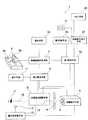
請求項1に係る発明は、例えば図1に例示するものであって、被検者に視標(2)を呈示する視標呈示手段(A)と、
該呈示された視標(2)と被検眼(4)との間の光路(16)の長さを調整して、所定の視標距離を設定することの出来る光路長さ調整手段(B)と、
前記被検者により操作されて該被検者の視標認識の結果を信号として出力する操作手段(6a)と、
前記操作手段(6a)から出力される信号と、その時点での前記視標呈示手段(A)が前記被検者に呈示している視標(2)を対比することにより、前記被検者による視標認識の正誤を判定する視標認識判定手段(7)と、
前記視標呈示手段(A)及び前記光路長さ調整手段(B)を制御することに基づき、前記視標(2)の実際の大きさを略一定にして前記光路の長さを間欠的に変化させる検査パターンを実行して、前記視標認識判定手段(7)による視力測定を行う第1制御手段(9a)と、
前記第1制御手段(9a)により、前記視標を所定の略一定の大きさにして前記光路の長さを変化させて、所定の判定が終了した後に、前記視標の大きさを変更して、当該変更された大きさの視標に基づいて前記視力測定を行うように前記第1制御手段(9a)に指令する、第2制御手段(9b)と、を設けて構成した視力検査装置に関するものである。The invention according to
Optical path length adjustment means (B) capable of setting a predetermined target distance by adjusting the length of the optical path (16) between the presented visual target (2) and the eye to be examined (4). When,
An operation means (6a) operated by the subject to output a result of the target recognition of the subject as a signal;
By comparing the signal output from the operation means (6a) with the visual target (2) presented to the subject by the visual target presenting means (A) at that time, the subject A target recognition determination means (7) for determining the correctness of target recognition by
Based on controlling the optotype presenting means (A) and the optical path length adjusting means (B),the actual size of the optotype (2) is made substantially constant, andthe length of the optical path isintermittently set. A first control means (9a) for executing a test pattern to be changed and performing a visual acuity measurement by the visual target recognition judging means (7);
By the first control means (9a),the visual andtarget the in the predeterminedsubstantially constant magnitude by varying thelength of theoptical path,after a predetermined determination hasbeen completed, to changethe size of thetarget And a second control means (9b) for instructing the first control means (9a) to perform the visual acuity measurement based on thetarget of the changedsize. It is about.
請求項2に係る発明は、請求項1に係る発明において、前記視標(2)を透光性材料にて形成し、
該視標(2)の裏側に光源(234)を配置し、
該光源(234)を点灯・消灯させることに基づき前記視標(2)が間欠的に呈示されるようにし、
かつ、視標呈示中は前記光路(16)の長さを一定にするようにしたことを特徴とする。The invention according to
A light source (234) is arranged behind the target (2),
The target (2) is intermittently presented based on turning on / off the light source (234),
In addition, the length of the optical path (16) is made constant during the presentation of the visual target.
請求項3に係る発明は、請求項1に係る発明において、前記光路中にシャッター(図7(a) の符号14参照)を設け、
該シャッター(14)を開閉することに基づき前記視標(2)が間欠的に呈示されるようにし、
かつ、視標呈示中は前記光路(16)の長さを一定にするようにしたことを特徴とする。The invention according to
The target (2) is intermittently presented based on opening and closing the shutter (14),
In addition, the length of the optical path (16) is made constant during the presentation of the visual target.
請求項4に係る発明は、図10に例示するように、複数配置された請求項1に記載の視力検査装置(1)と、
これら複数の視力検査装置(1)が接続された中央管理装置(53)と、
前記視標(2)の実際の大きさを略一定にして前記光路(16)の長さを間欠的に変化させる検査パターンを記憶しているメモリ手段(20)と、
前記中央管理装置(53)に配置されて、前記検査パターンを実行させる検査実行指令手段(22)と、を設けて構成した視力検査設備に関する。As shown in FIG. 10, the invention according to
A central management device (53) to which the plurality of visual acuity testing devices (1) are connected;
The actual andsize substantially constant storesintermittentlycheck pattern to vary the length of the optical path (16) memory means ofsaid target (2)(20),
Wherein arranged in the central management unit (53), the inspection execution instruction means for executingthe test pattern (22), about the vision test equipment which is configured by providing the.
なお、括弧内の番号などは、図面における対応する要素を示す便宜的なものであり、従って、本記述は図面上の記載に限定拘束されるものではない。 Note that the numbers in parentheses are for the sake of convenience indicating the corresponding elements in the drawings, and therefore the present description is not limited to the descriptions on the drawings.
請求項1に係る発明によれば、被検者が操作手段を操作するだけで視力検査を実施することができ、検査者が装置を操作しながら質問し被検者が答えるという形式を採らなくても良いので、視力検査の手間や時間を軽減できる。また、この検査パターンによれば、視力検査に際しては、視標の実際の大きさは一定にして光路長さだけを変化させるだけなので、両方を変化させる場合に比べて視力算定時の誤差を少なくできる。さらに、視標は、被検者の視標認識が合った時点で別の大きさに変更すれば足り、視標の大きさを細かく変更して行く必要が無いので、その分、担持させておく視標の数も少なくでき、装置のコンパクト化を図ることができる。According to the first aspect of the present invention, it is possible to perform a visual acuity test simply by operating the operating means by the subject, and the examiner does not take a form of asking a question while operating the device and answering the subject. As a result, it is possible to reduce the labor and time of the eye test.Also, according to this test pattern, in the visual acuity test, the actual size of the target is kept constant and only the optical path length is changed, so that the error in calculating the visual acuity is less than when both are changed. it can. Furthermore, it is sufficient that the target is changed to a different size when the subject's target is recognized, and it is not necessary to change the size of the target finely. The number of targets to be placed can be reduced, and the apparatus can be made compact.
請求項2に係る発明によれば、目の調整力の影響を防ぐことができる。According to the invention which concerns on
請求項3に係る発明によれば、目の調整力の影響を防ぐことができる。According to the invention which concerns on
請求項5に係る発明によれば、複数の視力検査装置による視力検査を中央管理装置によって一元的に管理することができ、視力検査の手間や時間を軽減できる。 According to the fifth aspect of the present invention, visual acuity tests by a plurality of visual acuity inspection devices can be managed centrally by the central management device, and the labor and time for visual acuity inspection can be reduced.
以下、図1乃至図10に沿って、本発明の実施の形態について説明する。 Hereinafter, embodiments of the present invention will be described with reference to FIGS.
ここで、図1は、本発明に係る視力検査装置の構造の一例を示すブロック図であり、図2は、視力検査方法を説明するためのフローチャート図であり、図3は、視力の検査結果の一例を示す図である。また、図4は、第1検査パターンによって検査した結果を示す図であって、視標の見かけ上の大きさを第1パラメータとし光路長さを第2パラメータとした場合の検査結果を示す図であり、図5は、第2検査パターンによって検査した結果を示す図であって、視標の大きさを第2パラメータとし光路長さを第1パラメータとした場合の検査結果を示す図であり、図6は、第3検査パターンによって検査した結果を示す図であって、視標の実際の大きさを第1パラメータとし光路長さを第2パラメータとした場合の検査結果を示す図である。さらに、図7(a) は、本発明に係る視力検査装置の構造の一例を示す模式図であり、(b) は接眼部の構造の一例を示す模式図であり、(c) は操作手段の構造の一例を示す図である。また、図8は、本発明に係る視力検査装置の構造の一例を示す模式図であり、図9は、本発明に係る視力検査装置の構造の一例を示す模式図である。さらに、図10は、複数の視力検査装置を中央管理装置により集中管理するようにした視力検査設備の全体構成を示す模式図である。
(1) まず、本発明に係る視力検査装置の構成について説明する。Here, FIG. 1 is a block diagram showing an example of the structure of the visual acuity test apparatus according to the present invention, FIG. 2 is a flowchart for explaining the visual acuity test method, and FIG. 3 is a visual test result. It is a figure which shows an example. FIG. 4 is a diagram showing the result of inspection using the first inspection pattern, and shows the inspection result when the apparent size of the target is the first parameter and the optical path length is the second parameter. FIG. 5 is a diagram illustrating a result of inspection using the second inspection pattern, and is a diagram illustrating an inspection result when the size of the target is the second parameter and the optical path length is the first parameter. FIG. 6 is a diagram illustrating a result of inspection using the third inspection pattern, and is a diagram illustrating an inspection result when the actual size of the target is the first parameter and the optical path length is the second parameter. . Further, FIG. 7 (a) is a schematic diagram showing an example of the structure of the visual acuity test apparatus according to the present invention, (b) is a schematic diagram showing an example of the structure of the eyepiece, and (c) is an operation diagram. It is a figure which shows an example of the structure of a means. FIG. 8 is a schematic diagram showing an example of the structure of the visual acuity test apparatus according to the present invention, and FIG. 9 is a schematic diagram showing an example of the structure of the visual acuity test apparatus according to the present invention. Further, FIG. 10 is a schematic diagram showing an overall configuration of a visual acuity inspection facility in which a plurality of visual acuity inspection devices are centrally managed by a central management device.
(1) First, the configuration of the visual acuity test apparatus according to the present invention will be described.
本発明に係る視力検査装置1は、図1に示すように、被検者に視標2を呈示する視標呈示手段Aと、該呈示された視標2と被検眼4との間の光路16の長さを調整して、所定の視標距離を設定することの出来る光路長さ調整手段Bと、前記被検者により操作されて該被検者の視標認識の結果を信号として出力するジョイスティックレバー6a及び視力検査の開始を指示する測定開始スイッチ6bなどからなる操作手段6と、を備えている。 As shown in FIG. 1, the visual
ここで、“光路16の長さ”とは、一般的な“光路長(つまり、光学距離とも称されるものであって、屈折率が一定の媒質内で、二点間の或る経路に沿って進む光線について、経路に沿っての幾何学的長さ(距離)と屈折率との積)”を意味するのではなく、単に光路の幾何学的長さを意味するものとする。以下、本明細書において“光路長さ”とする。また、“視標距離”は、光路長さそれ自体ではなく、光路長さを実際の距離に換算したものを意味する。例えば、図7(a) (b) 及び図8では、符号17で示す接眼レンズを配置することにより、レンズを配置しないで同様の機能を実現させるときよりも光路長さを短くしているが(詳細は後述)、該接眼レンズ17を配置しなかった場合の実際の距離に換算したもの(レンズを配置した場合の見かけ上の距離)が“視標距離”に相当する。 Here, the “length of the
そして、視標認識判定手段7が設けられていて、該手段7により、前記操作手段6aから出力される信号と、その時点での前記視標呈示手段Aが前記被検者に呈示している視標2を対比することにより、前記被検者による視標認識の正誤を判定するように構成されている。また、前記視標呈示手段A及び前記光路長さ調整手段Bを制御する第1制御手段9aが設けられていて、前記光路長さ及び前記視標2の大きさの一方である第1パラメータを略一定にして他方の第2パラメータを変化させる検査パターンを実行して、前記視標認識判定手段7による視力測定を行うように構成されている。さらに、前記第1制御手段9aにより、所定の第1パラメータについて前記検査パターンを実行して(つまり、該第1パラメータを略一定にして前記第2パラメータを変化させて)、前記視標認識判定手段7による所定の判定が終了したら(例えば、前記視標認識判定手段7が前記被検者による視標認識が正しいと判定した場合に)、前記所定の第1パラメータを他の値に変更して、当該変更された第1パラメータに基づいて前記視力測定を行うように前記第1制御手段9aに指令する第2制御手段9bが配置されている。本実施の形態によれば、被検者が操作手段6aを操作するだけで視力検査を実施することができ、検査者が装置を操作しながら質問し被検者が答えるという形式を採らなくても良いので、視力検査の手間や時間を軽減できる。A target recognition determination means 7 is provided, and the
ところで、上述のように第1制御手段9aに実行させる検査パターンとしては、次の第1乃至第3検査パターンを挙げることができる。
・ 前記視標2の見かけ上の大きさを第1パラメータとして略一定にして前記光路長さを第2パラメータとして変化させる第1検査パターン(図4参照)、
・ 前記光路長さを第1パラメータとして略一定にして前記視標2の大きさを第2パラメータとして変化させる第2検査パターン(図5参照)、及び
・ 前記視標2の実際の大きさを第1パラメータとして略一定にして前記光路長さを第2パラメータとして変化させる第3検査パターン(図6参照)、By the way, as the inspection pattern to be executed by the first control means 9a as described above, the following first to third inspection patterns can be exemplified.
A first inspection pattern (see FIG. 4) in which the apparent size of the
A second inspection pattern (see FIG. 5) in which the optical path length is made substantially constant as the first parameter and the size of the
ここで、“視標の見かけ上の大きさを一定にして前記光路長さを変化”とは、光路長さが長くても短くても被検者には視標のサイズが同じに見えるように、視標の実際の大きさを変化させている状態をいい、“視標の実際の大きさを一定にして前記光路長さを変化”とは、光路長さが長い場合には視標が小さく見え、光路長さが短くなるに従って視標が大きく見える状態をいう。本実施の形態によれば、視力測定のニーズに応じた多様な測定法を提供することができる。例えば、第1検査パターンによれば、視標があたかも静止していて変化していないように見えるので被検者に違和感を与えることなく視力検査を実施できる。第2検査パターンによれば、光路長さは一定にして視標の大きさだけを変化させるだけなので、両方を変化させる場合に比べて視力算定時の誤差を少なくできる。第3検査パターンによれば、視標の実際の大きさは一定にして光路長さだけを変化させるだけなので、視標は、被検者の視認結果が合った時点で別の大きさに変更すれば足り、視標の大きさを細かく変更して行く必要がないので、その分、担持させておく視標の数も少なくでき、装置のコンパクト化を図ることができる。なお、この場合、目の調節力の影響を防ぐため、視標の光源(例えば、図7(a) の符号234参照)を点灯・消灯することにより視標の呈示を間欠的に行い、かつ光源点灯中の数秒間は光路の長さを一定にさせておくのが望ましい。 Here, “change the optical path length while keeping the apparent size of the target constant” means that the target size looks the same to the subject regardless of whether the optical path length is long or short. The actual size of the target is changed, and “the optical path length is changed while keeping the actual size of the target constant” refers to the target when the optical path length is long. Means that the target looks larger as the optical path length becomes shorter. According to the present embodiment, it is possible to provide various measurement methods according to the needs of visual acuity measurement. For example, according to the first inspection pattern, the visual acuity test can be performed without giving a sense of incongruity to the subject because the visual target appears to be stationary and not changed. According to the second inspection pattern, since the optical path length is fixed and only the size of the target is changed, an error in calculating the visual acuity can be reduced as compared with the case where both are changed. According to the third test pattern, the actual size of the target is kept constant, and only the optical path length is changed. Therefore, the target is changed to another size when the visual recognition result of the subject matches. As a result, it is not necessary to finely change the size of the target, and accordingly, the number of targets to be carried can be reduced and the apparatus can be made compact. In this case, in order to prevent the influence of the eye accommodation, the target is presented intermittently by turning on / off the light source of the target (see, for example,
ところで、上述した検査パターンの内の少なくとも1つをメモリ手段20に記憶させておいて、前記第1制御手段9aが、前記メモリ手段20のデータに従い検査パターンを実行するようにすると良い。 By the way, it is preferable that at least one of the above-described inspection patterns is stored in the memory means 20 so that the first control means 9a executes the inspection pattern according to the data in the memory means 20.
上述した検査パターンの内の少なくとも2つをメモリ手段20に記憶させておいて、検査パターン選択手段21を設けて、選択手段21からのパターン選択信号に応じて検査実行指令手段22がメモリ手段20に記憶されている検査パターンから、実行すべき検査パターンを選択し、前記第1制御手段9aに指令を送って、前記検査パターン選択手段21により選択された検査パターンを実行させるようにしても良い。この構成によれば、被検者のニーズ等に応じて検査パターンを変更することができる。なお、検査パターン選択手段21はボタンやスイッチにより構成すると良い。 At least two of the above-described inspection patterns are stored in the memory means 20, an inspection pattern selection means 21 is provided, and the inspection execution command means 22 is in response to a pattern selection signal from the selection means 21 and the memory means 20. The inspection pattern to be executed may be selected from the inspection patterns stored in, and a command may be sent to the first control means 9a to cause the inspection pattern selected by the inspection pattern selection means 21 to be executed. . According to this configuration, the inspection pattern can be changed according to the needs of the subject. The inspection pattern selection means 21 may be constituted by buttons and switches.
さらに、図1に示すように、前記光路長さと前記視標2の大きさとの関係から該光路長さにおける被検者の視力(視標距離別の視力)を算定する視力算定手段8、を配置し、該視力算定手段8による視力の算定は、前記操作手段6aが前記被検者により操作されると共に前記視標認識判定手段7が所定の判定(例えば、前記被検者による視標認識が正しいという判定)をした場合に実行されるようにすると良い。そのようにした場合には、視力の算定は視力算定手段8によって自動的に行われ、人が算定する必要が無いので、視力検査の手間や時間を軽減でき、算定ミスも回避できる。 Further, as shown in FIG. 1, a visual acuity calculating means 8 for calculating the visual acuity of the subject in the optical path length (visual acuity for each visual target distance) from the relationship between the optical path length and the size of the
ところで、被検者の瞳孔径を測定する瞳孔径測定手段15を設けると共に、該瞳孔径測定手段15により測定された瞳孔径に応じて前記視標2の明るさ、背景光の明るさ又は前眼部照明の強度を調整するための調整手段(不図示)を前記視標呈示手段Aに設けておいて、適正な視力測定を行えるようにしても良い。例えば、前記瞳孔径測定手段15により測定される瞳孔径が所定の大きさ(即ち、測定に適した大きさ、或いは測定者が望む大きさの瞳孔径)となるように、前記調整手段によって視標の明るさ、背景光の明るさ、前眼部照明の光量を調整するようにすると良い。そのようにした場合には、瞳孔径の大きさ別に視力を測定することができる。この瞳孔径測定手段15は、被検者の瞳孔径を測定するセンサ12、及び該センサ12からの結果に基づき瞳孔径を演算する瞳孔径演算手段13により構成すると良い。センサ12としてはCCDを挙げることができる。視標の明るさを調整する方法としては、図7(a) に示すように、視標担持体231に透光性材料にて視標を形成し、視標担持体231の裏側に光源234を配置しておいて、該光源234の明るさを瞳孔径演算手段13及び視標制御部232により制御する方法を挙げることができる。 By the way, the pupil diameter measuring means 15 for measuring the pupil diameter of the subject is provided, and the brightness of the
なお、図7(a) 、図8及び図9に示すように、被検眼4に対向する位置には、被検眼4の視軸(視線)18aに対して傾くように第1ハーフミラーM1を配置して光軸を屈曲させ(図7(a) 及び図8の符号18b参照、図9の符号18b1参照)、後述する視標担持体231,331の視標2に対峙する位置には、前記屈曲された光軸18b、18b1に対して傾くように第2ハーフミラーM2を配置すると良い。このように構成した場合には、視標担持体231,331の視標の像は、第2ハーフミラーM2にて下方に反射されて光軸18b,18b1を辿り、鏡251,351,451,452,453にて反射された後は第2ハーフミラーM2を透過して第1ハーフミラーM1に反射されて、被検眼4に到達することとなる。7A, 8, and 9, the first half mirror M1 is tilted with respect to the visual axis (line of sight) 18 a of the
ところで、上述したセンサ12は、第1ハーフミラーM1を挟んで被検眼4に対向する位置(つまり、視軸の延長線18a´上)に配置すると良い。このように構成した場合には、光の一部が第1ハーフミラーM1を透過することを利用して被検眼4の瞳孔径を測定することができる。また、センサー12は、視標2の光路(符号18b、18b1で示す光軸)とは干渉しない位置に配置することができる。Incidentally, the
また、上述した視力算定手段8に、プリンタやモニタなどの表示手段11を接続して、算定された視力と視標距離との関係(図3参照)を表示するようにすると良い。なお、図7(b) に示すように、接眼レンズ17を2つ、シャッター19を2つ設けておいて、それらのシャッターを開閉することにより、左眼、右眼、両眼のそれぞれについて測定を行えるようにすると良い。 In addition, it is preferable to display the relationship between the calculated visual acuity and the target distance (see FIG. 3) by connecting display means 11 such as a printer or a monitor to the visual acuity calculation means 8 described above. As shown in FIG. 7 (b), two
さらに、上述したように視標が間欠的に視認されるようにするために視標の光源234を点灯/消灯させるようにしても良いが、シャッターを設けると共に該シャッターを開閉することにより視標が間欠的に視認されるようにしても良い。このシャッターを被検眼4の近くに配置して視標の見え方に影響が出るような場合には視標2の近く(図7(a) 及び図9に符号14参照)に配置すると良い。 Further, as described above, the target
ところで、図10に示すように、複数の視力検査装置1と、複数の検査パターンを記憶するメモリ手段20と、これら複数の検査パターンの中から実行すべき検査パターンを選択する検査パターン選択手段53a(21)と、前記各視力検査装置の第1制御手段9aに指令を選択的に送って前記選択された検査パターンによる視力測定を前記第1制御手段9aに実行させる検査実行指令手段22が配置された中央管理装置53と、によって視力検査設備を構成すると良い。このような視力検査設備によれば、複数の視力検査装置1による視力検査をオペレータが中央管理装置53によって一元的に管理することができ、視力検査の手間や時間を軽減できる。 By the way, as shown in FIG. 10, a plurality of visual
なお、視力検査装置1は、視標呈示手段A、光路長さ調整手段B、操作手段6a、視標認識判定手段7、第1制御手段9a及び第2制御手段9bによって構成すると良い。 The visual
また、視力検査装置1と中央管理装置53とは、通信回線50、ハブ51及び通信回線52によって接続すると良い。 The visual
ところで、図10では、メモリ手段20は中央管理装置53の側に配置されているが、図1に示すように視力検査装置1の側に配置しても良い。このメモリ手段20には、上述した第1乃至第3検査パターンの少なくとも2つを記憶させておくと良い。また、検査実行指令手段22は前記中央管理装置53の側に配置しておくと良い。 In FIG. 10, the memory means 20 is disposed on the
検査パターン選択手段53aによる検査パターンの選択は、視力検査装置毎に別々に行えるようにすると良い。
(2) 次に、各構成部品の具体的構成について、図7乃至図9に沿って説明する。
(2-1) 視標呈示手段についてThe selection of the inspection pattern by the inspection pattern selection means 53a may be performed separately for each eyesight inspection apparatus.
(2) Next, a specific configuration of each component will be described with reference to FIGS.
(2-1) Target presentation means
視標呈示手段は、
・ 図7(a) 及び図9に符号A1で示すように、種々の視標を担持すると共に移動自在に構成された視標担持体231と、特定の視標が被検者に視認される位置まで該視標担持体231を移動させる視標制御部232と、により構成して、視標それ自体を視認させるようにしても、
・ 図8に符号A2で示すように、視標2を担持する視標担持体331と、該担持された視標2の虚像を形成する光学系333と、該光学系333の光軸方向の位置を制御して虚像の大きさを調整する視標制御部332と、により構成して、視標の虚像を視認させるようにしても、
良い。The target presentation means is
- FIGS. 7 (a) and as indicated by reference numeral A1 in FIG. 9, the
- as indicated at A2 in FIG. 8, the
good.
図7(a) 及び図9に示す視標担持体231は、回転自在に支持された円板であるが、円板以外のものでも、回転以外の駆動をされるものでも良い。 The
図7(a) 及び図9の装置の場合には、視標担持体231に種々の大きさの視標を担持させておいて、視標の大きさを変更する場合には、視標担持体231を順次移動させる必要がある。一方の図8の装置の場合には、視標の大きさは光学系333及び視標制御部332により調整できるので、異なる大きさの視標を視標担持体331に担持させておく必要は無く、その分、視標担持体331をコンパクトにできる。例えば、視標にランドルト環を用いる場合には、切れ目の位置が上下左右の4種類だけを担持させておけば足りる。
(2-2) 光路長さ調整手段についてIn the case of the apparatus shown in FIGS. 7 (a) and 9, when a target having various sizes is supported on the
(2-2) Optical path length adjustment means
光路長さ調整手段は、
・ 図7(a) に符号B1で示すように、光軸18bに沿って移動自在に支持された平面鏡251と、該平面鏡251の位置を制御する光路長さ制御部252と、により構成しても、
・ 図8に符号B2で示すように、光軸18bに沿って移動自在に支持された凹面鏡351と、該凹面鏡351の位置を制御する光路長さ制御部352と、により構成しても、
良い。The optical path length adjusting means is
- as indicated at B1 in FIG. 7 (a), the
- as indicated at B2 in FIG. 8, a
good.
ところで、鏡251,351を移動して光路長さを0.3mから10mまでに変化させることが出来れば、図3に示す範囲(0.3m〜10m)の視標距離での視力測定が可能となるが、装置が大型化すると共に、大きな設置スペースも必要となってしまう。これを回避する方法としては、
・ 図7(a) (b) 及び図8に符号17で示すように接眼レンズを配置して、光路長さを短くする方法や、
・ 図9に示すように、光軸18b1,18b2に対して傾いた位置に配置される平面鏡451,452と、光軸18b2に対して直交するように配置される平面鏡453とを配置して、光軸18b1,18b2を折り返す方法、
を挙げることができる。なお、図9に示す装置においても、平面鏡451,452を光軸18b1,18b2に沿って移動自在にすると共に、平面鏡451,452の位置を光路長さ制御部454にて制御することにより、光路長さ調整手段B3を構成することができる。また、図9では、光軸18b1,18b2は1回だけ折り返されているが複数回折り返すようにしても良い。By the way, if the
A method of shortening the optical path length by arranging an eyepiece as shown by
As shown in FIG. 9, the plane mirrors 451 and 452 arranged at positions inclined with respect to the
Can be mentioned. 9, the plane mirrors 451 and 452 can be moved along the
ところで、図9のように平面鏡451,452,453を用いた構造のものでは、視標を変更しない状態では、光路長さが短くなるに従って視標は大きくなってしまい、図6の第3検査パターンのような計測は行えるものの、図4の第1検査パターンのような計測は行えない。第1検査パターンを実行するには、平面鏡451,452の位置に応じて視標担持体231の位置を制御し、視標の実際のサイズを変更して見かけ上のサイズを略一定にしてやる必要がある。また、第2検査パターンを実行するには、平面鏡451,452を所定位置に停止させた状況下で視標担持体231の位置を制御し、視標のサイズを所定のステップで大きくしてやる必要がある。これに対し、図7(a) に示す構成のものでは、レンズ17の作用により平面鏡251の位置に関係なく視標の見かけの大きさを一定にすることができる。 By the way, in the structure using the plane mirrors 451, 452, and 453 as shown in FIG. 9, the target becomes larger as the optical path length becomes shorter in the state where the target is not changed, and the third inspection shown in FIG. Although measurement like a pattern can be performed, measurement like the 1st inspection pattern of
一方、図8に示す構成のものでは、光学系333で、視標の大きさを調節してから凹面鏡351に平行光が入射されるようにすることにより、凹面鏡351の位置に関係なく、視標の見かけ上の大きさを略一定にできる。このため、検査時の駆動を簡素化でき、第1検査パターンの計測が容易となる。また、凹面鏡351の位置調整と光学系333の位置調整とをリンクさせることにより、第2検査パターンや第3検査パターンの計測もすることができる。
(2-3) 操作手段についてOn the other hand, in the configuration shown in FIG. 8, the
(2-3) Operation method
視標認識の結果を信号として出力する操作手段6aとしては、レバー型スイッチや押しボタン等を挙げることができる。視標にランドルト環を用いて切れ目の位置を答えてもらうようにする場合には、上下左右に傾動可能なジョイスティック(図7(c) 参照)や、上下左右に配置した4つの押しボタンなどを使用すれば良い。
(3) 次に、図1に示す装置を用いた視力検査方法について図2を参照して説明する。但し、説明の便宜上、メモリ手段20には検査パターンが1つだけ記憶されていて、検査パターンの選択ができないように構成されているとする。Examples of the operation means 6a that outputs the result of the target recognition as a signal include a lever type switch and a push button. When using the Landolt ring as a target to answer the position of the cut, use a joystick (see Fig. 7 (c)) that can be tilted up and down, left and right, and four push buttons arranged vertically and horizontally. Use it.
(3) Next, a vision test method using the apparatus shown in FIG. 1 will be described with reference to FIG. However, for convenience of explanation, it is assumed that only one inspection pattern is stored in the memory means 20 so that the inspection pattern cannot be selected.
被検者が、装置の接眼部(不図示)に眼を当てながら測定開始スイッチ6bを押すと、該スイッチ6bからの信号が第1制御手段9aに送られて、該制御手段9aは、検査パターンについてのデータをメモリ手段20から読み出し、前記視標呈示手段Aに視標2を呈示させると共に前記光路長さ調整手段Bにより光路長さを調整させて該検査パターン(つまり、前記第1乃至第3検査パターンのいずれか)を実行する。その結果、前記第1パラメータ(前記光路16の長さ及び前記視標2の大きさの一方)が略一定とされて前記第2パラメータ(前記光路16の長さ及び前記視標2の大きさの他方)が変化される(図2のS1参照)。 When the subject presses the
このとき、第2パラメータは、被検者に視標2が視認され易くなる方向に変化される。例えば、視標の大きさが第2パラメータとして選択されている場合には該視標のサイズが所定のステップで大きくなって行き、光路長さが第2パラメータとして選択されている場合には、
・ 後述のような“(a) 遠距離側の検査”においては該光路長さが所定のステップで短くなって行き、
・ 後述のような“(b) 近距離側の検査”においては該光路長さが所定のステップで長くなって行く(詳細は後述する)。At this time, the second parameter is changed in a direction in which the
・ In “(a) Long-distance inspection” as described later, the optical path length decreases in a predetermined step,
In “(b) Short-distance side inspection” as described later, the optical path length increases in a predetermined step (details will be described later).
その間、被検者は、前記視標呈示手段Aにより呈示される視標2を注視し、視標2を認識できたときにジョイスティックレバー(操作手段)6aを操作すると(図2のS2参照)、その信号(視標認識の結果を示す信号)が視標認識判定手段7に送られて、被検者の視標認識の正誤が判定され(図2のS3参照)、視標認識判定手段7による視力測定が実行される。 Meanwhile, when the subject gazes at the
前記被検者による視標認識が正しいと前記視標認識判定手段7が所定の判定(例えば、前記被検者による視標認識が正しいとする判定)をした場合は、該判定手段7からの信号が第2制御手段9bに送られ、該第2制御手段9bは前記所定の第1パラメータを他の値に変更して、当該変更された第1パラメータに基づいて前記視力測定を行うように前記第1制御手段9aに指令する(図2のS4,S5参照)。その結果、前記第1制御手段9aは、変更された第1パラメータを略一定にして第2パラメータを変化させて次の視力測定(つまり、新たな第1パラメータ下での視力測定)を実行する(図2のS1参照)。When the target recognition by the subject is correct and the target recognition determination means 7 makes a predetermined determination (for example, determination that the target recognition by the subject is correct), the determination means 7 A signal is sent to the second control means 9b, and the second control means 9b changes the predetermined first parameter to another value and performs the visual acuity measurement based onthe changedfirst parameter. Commands the first control means 9a (see S4 and S5 in FIG. 2). As a result, the first control means 9a performs the next visual acuity measurement (that is, visual acuity measurement under the new first parameter) by changing the second parameter while keeping the changed first parameter substantially constant. (See S1 in FIG. 2).
ところで、被検者の視標認識が間違っていると前記視標認識判定手段7が判定した場合には、前記第2制御手段9bによる第1パラメータの変更は行わせないで、同じ第1パラメータでの視力検査を続行させる(図2のS3,S1参照)。なお、前記視標認識判定手段7に報知手段(図1の符号10参照)を接続しておいて、被検者の視標認識が間違っていると前記視標認識判定手段7が判断した場合にはその旨を被検者に報知するようにしても良い(図2のS7参照)。この報知手段10としては、チャイムやブザー等を挙げることができる。 By the way, when the target
なお、メモリ手段20に複数の検査パターンが記憶されていて、検査パターン選択手段21により検査パターンを自由に選択できるように構成されている場合には、測定開始スイッチ6bを押す前に被検者又は検査者が検査パターン選択手段21を操作すれば良い。すると、検査実行指令手段22は前記第1制御手段9aに指令を送って、選択された検査パターンを実行させる。 In the case where a plurality of test patterns are stored in the memory means 20 and the test pattern selection means 21 is configured so that the test patterns can be freely selected, the subject before pressing the
また、図10に示す装置を用いた場合の視力検査方法は、上述した検査方法とほぼ同様であるが、検査パターン選択手段53aの操作は検査者が行うこととなる。
(4) さらに、上述した視力検査方法の具体例を図4乃至図6を参照して説明する。
《第1検査パターン》Further, the visual acuity inspection method using the apparatus shown in FIG. 10 is substantially the same as the above-described inspection method, but the inspection pattern selection means 53a is operated by the inspector.
(4) Furthermore, a specific example of the above-described visual acuity inspection method will be described with reference to FIGS.
<< First inspection pattern >>
図4は、第1検査パターンによって検査した結果を示す図であって、視標の見かけ上の大きさを第1パラメータとし光路長さを第2パラメータとした場合の検査結果を示す図である。 FIG. 4 is a diagram illustrating a result of inspection using the first inspection pattern, and is a diagram illustrating an inspection result when the apparent size of the target is the first parameter and the optical path length is the second parameter. .
本検査パターンでは、(a) 遠距離側の検査と、(b) 近距離側の検査とを行う。以下、それぞれについて説明する。
(a) 遠距離側の検査In this inspection pattern, (a) inspection on the long distance side and (b) inspection on the short distance side are performed. Each will be described below.
(a) Long-distance inspection
視標の見かけ上の大きさを“視力1.5相当”のサイズにしておいて、光路長さ(正確には視標距離)を∞(無限遠)から所定のステップで短くして行く。その視標が視認されず第2パラメータが0.3mになると、視標の見かけ上の大きさを視力1.5相当から1.2相当のものへ変更する(図2のS8,S5参照)。 The apparent size of the visual target is set to a size corresponding to “visual acuity 1.5”, and the optical path length (accurately, the visual target distance) is shortened in a predetermined step from ∞ (infinity). When the target is not visually recognized and the second parameter becomes 0.3 m, the apparent size of the target is changed from the equivalent of the visual acuity 1.5 to the equivalent of 1.2 (see S8 and S5 in FIG. 2). .
その状態で光路長さを∞(無限遠)から短くして行くが、いま、被検者が視標距離5mのところで操作手段6aを操作したとする(図2のS2参照)。被検者の視標認識が正しいと判断されれば、視標の見かけ上の大きさを視力1.0相当に変更して(図2のS3,S4,S5参照)、同様の検査を繰り返す(同図のS1参照)。視標の見かけ上の大きさは、視力0.7相当→視力0.5相当→視力0.1相当と所定のステップで小さくして、それぞれについて視力を検査していく(同図のS1〜S4参照)。
(b) 近距離側の検査In this state, the optical path length is shortened from ∞ (infinite), but it is assumed that the subject operates the operating means 6a at a target distance of 5 m (see S2 in FIG. 2). If it is determined that the subject's target recognition is correct, the apparent size of the target is changed to a visual acuity equivalent to 1.0 (see S3, S4, and S5 in FIG. 2), and the same examination is repeated. (See S1 in the figure). The apparent size of the visual target is reduced by a predetermined step such that the visual acuity is equivalent to 0.7 → the visual acuity equivalent to 0.5 → the visual acuity equivalent to 0.1, and the visual acuity is examined for each of them (S1 to S1 in the figure). (See S4).
(b) Short-distance inspection
視標の見かけ上の大きさを視力1.2相当にしておいて、光路長さ(正確には視標距離)を0.3mから0.5m、1mと長くしていく。被検者が1mのところで操作手段6aを操作したとして、その視標認識が正しいと判断されれば、視標の見かけ上の大きさを視力1.0相当に変更して(図2のS3,S4,S5参照)、同様の検査を繰り返す(同図のS1参照)。視標の見かけ上の大きさはは、視力0.7相当→視力0.5相当→視力0.1相当と所定のステップで小さくして、それぞれについて視力を検査していく(同図のS1〜S4参照)。 The apparent size of the visual target is set to be equivalent to the visual acuity 1.2, and the optical path length (accurately, the visual target distance) is increased from 0.3 m to 0.5 m and 1 m. If the subject operates the operating means 6a at 1 m and the target recognition is determined to be correct, the apparent size of the target is changed to a visual acuity equivalent to 1.0 (S3 in FIG. 2). , S4, S5), and the same inspection is repeated (see S1 in the figure). The apparent size of the visual target is reduced in a predetermined step such that the visual acuity is equivalent to 0.7 → the visual acuity equivalent to 0.5 → the visual acuity equivalent to 0.1, and the visual acuity is inspected for each (S1 in FIG. To S4).
なお、全ての測定が終了した場合には、表示手段11により測定結果を表示するようにすると良い(同図のS4,S5参照)。 When all measurements are completed, the measurement result may be displayed on the display means 11 (see S4 and S5 in the figure).
この検査パターンによれば、光路長さが変化しても視標2の見かけ上の大きさは略一定なので、被検者には、視標2の位置があたかも変化していないような印象を与える。その結果、被検者に違和感を与えることなく視力検査を実施できる。
《第2検査パターン》According to this test pattern, the apparent size of the
<< 2nd inspection pattern >>
図5は、第2検査パターンによって検査した結果を示す図であって、視標の大きさを第2パラメータとし光路長さを第1パラメータとした場合の検査結果を示す図である。 FIG. 5 is a diagram illustrating a result of inspection using the second inspection pattern, and is a diagram illustrating an inspection result when the size of the target is the second parameter and the optical path length is the first parameter.
光路長さを例えば∞(無限遠)に設定し、視標サイズを小さくしておいて、光路長さはそのままにして視標サイズを所定のステップで大きくして行く。被検者は操作手段6aを操作することにより視力が0.7であることが分かる(図2のS1,S2,S3参照)。 For example, the optical path length is set to ∞ (infinity), the target size is reduced, and the target size is increased in a predetermined step while leaving the optical path length unchanged. The subject can see that the visual acuity is 0.7 by operating the operating means 6a (see S1, S2, and S3 in FIG. 2).
次に、第1パラメータである光路長さを10mに変更し、視標サイズをリセットして最小サイズとする(図2のS5参照)。被検者は操作手段6aを操作することにより視力が1.2であることが分かる。同様の検査を、各光路長さにつき行うことにより、図5に示すような折れ線を求めることができる。 Next, the optical path length as the first parameter is changed to 10 m, and the target size is reset to the minimum size (see S5 in FIG. 2). The subject can see that the visual acuity is 1.2 by operating the operating means 6a. By performing the same inspection for each optical path length, a broken line as shown in FIG. 5 can be obtained.
本検査パターンによれば、視力検査に際しては、光路長さは一定にして視標2の大きさだけを変化させるだけなので、両方を変化させる場合に比べて視力算定時の誤差を少なくできる。
《第3検査パターン》According to this test pattern, in the visual acuity test, the optical path length is kept constant and only the size of the
<< Third inspection pattern >>
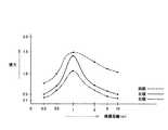
図6は、第3検査パターンによって検査した結果を示す図であって、視標の実際の大きさを第1パラメータとし光路長さを第2パラメータとした場合の検査結果を示す図である。図中の×印は、被検者により操作手段6が操作されなかったり、操作されても視標認識判定手段7により“誤判定”と判断されたポイントを示し、図中の●印は、視標認識判定手段7により“正しい判定”と判断されたポイントを示す。 FIG. 6 is a diagram illustrating a result of inspection using the third inspection pattern, and is a diagram illustrating an inspection result when the actual size of the target is the first parameter and the optical path length is the second parameter. The x mark in the figure indicates a point where the operation means 6 is not operated by the subject or is judged as “false determination” by the target recognition determination means 7 even if it is operated. The points determined as “correct determination” by the target recognition determination means 7 are shown.
第1検査パターンでは、視標の見かけ上の大きさを一定にしていて、光路長さが長くても短くても視標は同じ大きさに見えるようにしたが、本検査パターンでは、視標の実際の大きさを一定にして第1パラメータとし、光路長さを第2パラメータとした。したがって、光路長さが長い場合には視標は小さく見え、光路長さが短い場合には視標は大きく見えることとなる。 In the first inspection pattern, the apparent size of the target is fixed, and the target looks the same regardless of whether the optical path length is long or short. The actual size of the optical path length is fixed as the first parameter, and the optical path length is set as the second parameter. Therefore, when the optical path length is long, the visual target looks small, and when the optical path length is short, the visual target looks large.
本検査パターンでも、(a) 遠距離側の検査と、(b) 近距離側の検査とを行う。以下、それぞれについて説明する。
(a) 遠距離側の検査Even in this inspection pattern, (a) inspection on the long distance side and (b) inspection on the short distance side are performed. Each will be described below.
(a) Long-distance inspection
視標を所定の大きさにしておいて、光路長さ(第2パラメータ)を∞(無限遠)から所定のステップで短くして行く。被検者からの応答があり(図2のS2参照)、その視標認識が合っている場合には(図2のS3参照)、視標のサイズを1段階小さくして、同様の検査を繰り返す(図2のS5,S1参照)。
(b) 近距離側の検査The target is set to a predetermined size, and the optical path length (second parameter) is shortened from ∞ (infinity) in a predetermined step. If there is a response from the subject (see S2 in FIG. 2) and the target recognition is correct (see S3 in FIG. 2), the target size is reduced by one step and the same test is performed. Repeat (see S5 and S1 in FIG. 2).
(b) Short-distance inspection
視標を所定の大きさにしておいて、光路長さ(第2パラメータ)を0.3mから所定のステップで長くして行く。被検者からの応答があり(図2のS2参照)、その視標認識が合っている場合には(図2のS3参照)、視標のサイズを1段階小さくして、同様の検査を繰り返す(図2のS5,S1参照)。 The target is set to a predetermined size, and the optical path length (second parameter) is increased from 0.3 m in a predetermined step. If there is a response from the subject (see S2 in FIG. 2) and the target recognition is correct (see S3 in FIG. 2), the target size is reduced by one step and the same test is performed. Repeat (see S5 and S1 in FIG. 2).
なお、図6では、視力と視標距離との関係がリニアな関係になっているが、リニアな関係でなくても本検査方法を適用できる。その場合には、データテーブルを用意しておいて、視標の大きさと視標距離(光路長さ)とに基づき視力が求まるようにしておくと良い。 In FIG. 6, the relationship between the visual acuity and the target distance is a linear relationship, but the present inspection method can be applied even if it is not a linear relationship. In that case, it is preferable to prepare a data table so that the visual acuity is obtained based on the size of the target and the target distance (optical path length).
この第3検査パターンによれば、視力検査に際しては、視標2の実際の大きさは一定にして光路長さだけを変化させるだけなので、両方を変化させる場合に比べて視力算定時の誤差を少なくできる。また、視標2は、被検者の視標認識が合った時点で別の大きさに変更すれば足り、視標2の大きさを細かく変更して行く必要がないので、その分、担持させておく視標の数も少なくでき、装置のコンパクト化を図ることができる。なお、この場合、目の調節力の影響を防ぐため、上述のように視標の光源(図7(a) の符号234参照)を点灯・消灯させたりシャッターを開閉させたりすることにより視標の呈示を間欠的に行い、かつ視標呈示中の数秒間は光路の長さを一定にさせておくのが望ましい。 According to the third test pattern, in the visual acuity test, since the actual size of the
ところで、上述した第1〜第3検査パターンは、組み合せて用いても、或いは、上述のように検査パターン選択手段21によって適宜選択できるようにしても良い。 By the way, the first to third inspection patterns described above may be used in combination, or may be appropriately selected by the inspection pattern selection means 21 as described above.
1 視力検査装置
2 視標
4 被検眼
6 操作手段
7 視標認識判定手段
8 視力算定手段
9a 第1制御手段
9b 第2制御手段
15 瞳孔径測定手段
16 光路
231 視標担持体
232 視標制御部
252 光路長さ制御部
331 視標担持体
332 視標制御部
333 光学系
351 凹面鏡
352 光路長さ制御部
454 光路長さ制御部
A 視標呈示手段
A1 視標呈示手段
A2 視標呈示手段
B 光路長さ調整手段
B1 光路長さ調整手段
B2 光路長さ調整手段
B3 光路長さ調整手段DESCRIPTION OF
Claims (4)
Translated fromJapanese該呈示された視標と被検眼との間の光路の長さを調整して、所定の視標距離を設定することの出来る光路長さ調整手段と、
前記被検者により操作されて該被検者の視標認識の結果を信号として出力する操作手段と、
前記操作手段から出力される信号と、その時点での前記視標呈示手段が前記被検者に呈示している視標を対比することにより、前記被検者による視標認識の正誤を判定する視標認識判定手段と、
前記視標呈示手段及び前記光路長さ調整手段を制御することに基づき、前記視標の実際の大きさを略一定にして前記光路の長さを間欠的に変化させる検査パターンを実行して、前記視標認識判定手段による視力測定を行う第1制御手段と、
前記第1制御手段により、前記視標を所定の略一定の大きさにして前記光路の長さを変化させて、所定の判定が終了した後に、前記視標の大きさを変更して、当該変更された大きさの視標に基づいて前記視力測定を行うように前記第1制御手段に指令する、第2制御手段と、
を設けて構成した視力検査装置。An optotype presenting means for presenting the optotype to the subject;
An optical path length adjusting means capable of setting a predetermined target distance by adjusting the length of the optical path between the presented target and the eye to be examined;
An operation means that is operated by the subject and outputs a result of the target recognition of the subject as a signal;
By comparing the signal output from the operation means with the target presented by the target presenting means at that time to the subject, it is determined whether or not the target is recognized by the subject. A target recognition determination means;
Based on controlling the optotype presenting means and the optical path length adjusting means, an inspection pattern for changingthe length of the optical pathintermittently while makingthe actual size of the optotype substantially constant, First control means for measuring visual acuity by the target recognition determination means;
Wherein the first control means,the visual andtarget the in the predeterminedsubstantially constant magnitude by varying thelength of theoptical path,after a predetermined determination hasbeen completed, by changingthe size of the optotype, the A second control means for instructing the first control means to perform the visual acuity measurement based on atarget having a changedsize ;
A visual acuity test apparatus configured by providing
該視標の裏側に光源を配置し、
該光源を点灯・消灯させることに基づき前記視標が間欠的に呈示されるようにし、
かつ、視標呈示中は前記光路の長さを一定にするようにした、
ことを特徴とする請求項1に記載の視力検査装置。Forming the target with a translucent material;
Place a light source on the back side of the target,
The target is intermittently presented based on turning on and off the light source,
And while the target is presented, the length of the optical path is made constant.
The visual acuity test apparatus according to claim 1.
該シャッターを開閉することに基づき前記視標が間欠的に呈示されるようにし、
かつ、視標呈示中は前記光路の長さを一定にするようにした、
ことを特徴とする請求項1に記載の視力検査装置。A shutter is provided in theoptical path ;
The target is intermittently presented based on opening and closing the shutter,
And while the target is presented, the length of the optical path is made constant.
The visual acuity test apparatus according to claim 1.
これら複数の視力検査装置が接続された中央管理装置と、
前記視標の実際の大きさを略一定にして前記光路の長さを間欠的に変化させる検査パターンを記憶しているメモリ手段と、
前記中央管理装置に配置されて、前記各視力検査装置の第1制御手段に指令を選択的に送って前記検査パターンを実行させる検査実行指令手段と、
を設けて構成した視力検査設備。A plurality of the visual acuity testing devices according to claim 1,
A central management device to which the plurality of visual acuity testing devices are connected;
A memory means for storing theintermittentlyinspection pattern to vary the length of the optical path with a substantially constant actual sizeofthetarget,
Are disposed in the central management device, and the test execution command means for the execution ofthe test pattern instructions to the first control means selectively to send it the respective vision testing device,
Visual inspection equipment that is configured with
Priority Applications (1)
| Application Number | Priority Date | Filing Date | Title |
|---|---|---|---|
| JP2003428793AJP4378165B2 (en) | 2003-12-25 | 2003-12-25 | VISION INSPECTION DEVICE, AND VISION INSPECTION EQUIPMENT HAVING THE VISION INSPECTION DEVICE |
Applications Claiming Priority (1)
| Application Number | Priority Date | Filing Date | Title |
|---|---|---|---|
| JP2003428793AJP4378165B2 (en) | 2003-12-25 | 2003-12-25 | VISION INSPECTION DEVICE, AND VISION INSPECTION EQUIPMENT HAVING THE VISION INSPECTION DEVICE |
Publications (2)
| Publication Number | Publication Date |
|---|---|
| JP2005185395A JP2005185395A (en) | 2005-07-14 |
| JP4378165B2true JP4378165B2 (en) | 2009-12-02 |
Family
ID=34787651
Family Applications (1)
| Application Number | Title | Priority Date | Filing Date |
|---|---|---|---|
| JP2003428793AExpired - Fee RelatedJP4378165B2 (en) | 2003-12-25 | 2003-12-25 | VISION INSPECTION DEVICE, AND VISION INSPECTION EQUIPMENT HAVING THE VISION INSPECTION DEVICE |
Country Status (1)
| Country | Link |
|---|---|
| JP (1) | JP4378165B2 (en) |
Families Citing this family (5)
| Publication number | Priority date | Publication date | Assignee | Title |
|---|---|---|---|---|
| JP5486488B2 (en)* | 2007-04-13 | 2014-05-07 | ナイキ インターナショナル リミテッド | Method for examining a subject's vision |
| US10485466B2 (en) | 2009-03-20 | 2019-11-26 | Cognisens Inc. | Device and method for measuring mild perceptual impairment |
| JP2013148599A (en)* | 2010-04-27 | 2013-08-01 | Panasonic Electric Works Co Ltd | Display device |
| CN103082988B (en)* | 2013-01-25 | 2015-06-17 | 深圳市莫廷影像技术有限公司 | Human vision parameter automatic testing method and device thereof |
| NL2035161B1 (en)* | 2022-07-01 | 2024-03-25 | Akkolens Int B V | Method to measure variable lens power |
- 2003
- 2003-12-25JPJP2003428793Apatent/JP4378165B2/ennot_activeExpired - Fee Related
Also Published As
| Publication number | Publication date |
|---|---|
| JP2005185395A (en) | 2005-07-14 |
Similar Documents
| Publication | Publication Date | Title |
|---|---|---|
| EP2949266A1 (en) | Ophthalmologic apparatus | |
| US9775507B2 (en) | Method of evaluating quality of vision in examinee's eye and storage medium | |
| JP2019063265A (en) | Subjective optometer | |
| WO2015102092A1 (en) | Ophthalmological device | |
| JP4378165B2 (en) | VISION INSPECTION DEVICE, AND VISION INSPECTION EQUIPMENT HAVING THE VISION INSPECTION DEVICE | |
| JP2018171139A (en) | A subjective optometry device | |
| JP4739795B2 (en) | Eye refractive power measuring device | |
| JP2005052249A (en) | Eye adjustment function measuring instrument | |
| JP4330399B2 (en) | Eye adjustment function measuring device | |
| JP6497005B2 (en) | Visual function measuring device and visual function measuring program | |
| JP6057061B2 (en) | Eye refractive power measuring device | |
| EP1649802B1 (en) | Eye adjustment function state measurement device and eye adjustment function state measurement method | |
| JP7647074B2 (en) | Subjective optometry device and subjective optometry program | |
| JP7574542B2 (en) | Optometry system, optometry controller, and optometry program | |
| JP7540181B2 (en) | Optometry Systems and Programs | |
| JP2018086304A (en) | Ophthalmic equipment | |
| JPH11285470A (en) | Ophthalmoscope | |
| JP3679258B2 (en) | Dynamic visual acuity testing device | |
| JP6962767B2 (en) | Ophthalmic equipment | |
| JPH0910177A (en) | Optometric apparatus | |
| JP2000185015A (en) | Visual acuity testing device | |
| JP4481712B2 (en) | Eye adjustment function measuring device | |
| JP4628761B2 (en) | Optometry equipment | |
| JP3478636B2 (en) | Optometry device | |
| JP2025120881A (en) | Subjective optometry device and optometry control program |
Legal Events
| Date | Code | Title | Description |
|---|---|---|---|
| A621 | Written request for application examination | Free format text:JAPANESE INTERMEDIATE CODE: A621 Effective date:20061128 | |
| A977 | Report on retrieval | Free format text:JAPANESE INTERMEDIATE CODE: A971007 Effective date:20090608 | |
| A131 | Notification of reasons for refusal | Free format text:JAPANESE INTERMEDIATE CODE: A131 Effective date:20090623 | |
| A521 | Request for written amendment filed | Free format text:JAPANESE INTERMEDIATE CODE: A523 Effective date:20090812 | |
| TRDD | Decision of grant or rejection written | ||
| A01 | Written decision to grant a patent or to grant a registration (utility model) | Free format text:JAPANESE INTERMEDIATE CODE: A01 Effective date:20090901 | |
| A01 | Written decision to grant a patent or to grant a registration (utility model) | Free format text:JAPANESE INTERMEDIATE CODE: A01 | |
| A61 | First payment of annual fees (during grant procedure) | Free format text:JAPANESE INTERMEDIATE CODE: A61 Effective date:20090914 | |
| R150 | Certificate of patent or registration of utility model | Free format text:JAPANESE INTERMEDIATE CODE: R150 | |
| FPAY | Renewal fee payment (event date is renewal date of database) | Free format text:PAYMENT UNTIL: 20120918 Year of fee payment:3 | |
| FPAY | Renewal fee payment (event date is renewal date of database) | Free format text:PAYMENT UNTIL: 20130918 Year of fee payment:4 | |
| R250 | Receipt of annual fees | Free format text:JAPANESE INTERMEDIATE CODE: R250 | |
| R250 | Receipt of annual fees | Free format text:JAPANESE INTERMEDIATE CODE: R250 | |
| LAPS | Cancellation because of no payment of annual fees |