JP4377452B1 - Substrate holder storage chamber, inline-type substrate processing apparatus, and magnetic disk manufacturing method - Google Patents
Substrate holder storage chamber, inline-type substrate processing apparatus, and magnetic disk manufacturing methodDownload PDFInfo
- Publication number
- JP4377452B1 JP4377452B1JP2009510222AJP2009510222AJP4377452B1JP 4377452 B1JP4377452 B1JP 4377452B1JP 2009510222 AJP2009510222 AJP 2009510222AJP 2009510222 AJP2009510222 AJP 2009510222AJP 4377452 B1JP4377452 B1JP 4377452B1
- Authority
- JP
- Japan
- Prior art keywords
- substrate holder
- substrate
- movable table
- storage chamber
- holding
- Prior art date
- Legal status (The legal status is an assumption and is not a legal conclusion. Google has not performed a legal analysis and makes no representation as to the accuracy of the status listed.)
- Active
Links
Images


Classifications
- H—ELECTRICITY
- H01—ELECTRIC ELEMENTS
- H01L—SEMICONDUCTOR DEVICES NOT COVERED BY CLASS H10
- H01L21/00—Processes or apparatus adapted for the manufacture or treatment of semiconductor or solid state devices or of parts thereof
- H01L21/67—Apparatus specially adapted for handling semiconductor or electric solid state devices during manufacture or treatment thereof; Apparatus specially adapted for handling wafers during manufacture or treatment of semiconductor or electric solid state devices or components ; Apparatus not specifically provided for elsewhere
- H01L21/673—Apparatus specially adapted for handling semiconductor or electric solid state devices during manufacture or treatment thereof; Apparatus specially adapted for handling wafers during manufacture or treatment of semiconductor or electric solid state devices or components ; Apparatus not specifically provided for elsewhere using specially adapted carriers or holders; Fixing the workpieces on such carriers or holders
- H01L21/67313—Horizontal boat type carrier whereby the substrates are vertically supported, e.g. comprising rod-shaped elements
- H—ELECTRICITY
- H01—ELECTRIC ELEMENTS
- H01L—SEMICONDUCTOR DEVICES NOT COVERED BY CLASS H10
- H01L21/00—Processes or apparatus adapted for the manufacture or treatment of semiconductor or solid state devices or of parts thereof
- H01L21/67—Apparatus specially adapted for handling semiconductor or electric solid state devices during manufacture or treatment thereof; Apparatus specially adapted for handling wafers during manufacture or treatment of semiconductor or electric solid state devices or components ; Apparatus not specifically provided for elsewhere
- H01L21/673—Apparatus specially adapted for handling semiconductor or electric solid state devices during manufacture or treatment thereof; Apparatus specially adapted for handling wafers during manufacture or treatment of semiconductor or electric solid state devices or components ; Apparatus not specifically provided for elsewhere using specially adapted carriers or holders; Fixing the workpieces on such carriers or holders
- H01L21/67346—Apparatus specially adapted for handling semiconductor or electric solid state devices during manufacture or treatment thereof; Apparatus specially adapted for handling wafers during manufacture or treatment of semiconductor or electric solid state devices or components ; Apparatus not specifically provided for elsewhere using specially adapted carriers or holders; Fixing the workpieces on such carriers or holders characterized by being specially adapted for supporting a single substrate or by comprising a stack of such individual supports
Landscapes
- Engineering & Computer Science (AREA)
- Physics & Mathematics (AREA)
- Condensed Matter Physics & Semiconductors (AREA)
- General Physics & Mathematics (AREA)
- Manufacturing & Machinery (AREA)
- Computer Hardware Design (AREA)
- Microelectronics & Electronic Packaging (AREA)
- Power Engineering (AREA)
- Container, Conveyance, Adherence, Positioning, Of Wafer (AREA)
- Manufacturing Of Magnetic Record Carriers (AREA)
Abstract
Translated fromJapaneseDescription
Translated fromJapanese インライン型基板処理装置で発生する基板ホルダー堆積膜対策として、基板ホルダー収納チャンバによる基板ホルダーの交換システムが特許文献1に開示されている。
特許文献1の基板ホルダー収納チャンバは、放射状に配置された搬送用ローラー付の複数の搬送レールと、その搬送レールを放射中心を軸として回転駆動する搬送レール回転機構を備え、各搬送レール上に基板ホルダーが搭載可能になっている。この搬送レールを収納チャンバに設けられた搬出入口(1ヶ所)に回転搬送する事で、収納チャンバー内の基板ホルダーをインライン型基板処理装置へ搬出(回収)する方式である。
The substrate holder storage chamber of
しかしながら、以下のような課題又は問題点があった。
(1)基板ホルダー収納チャンバの小型化
前記のように、従来技術では基板ホルダー収納に回転方式を採用している為、搬送レールの放射状配置が必要である。搬送レールの配置半径は内蔵レール数とレール間隔で決定され、内蔵する搬送レール数が多くなると放射中心より離して配置する必要が有る為に配置半径が広がってしまう。又、放射配置の特徴として中心付近の搬送レール間隔は放射角度により外周に向かい拡大する為、外周部に無駄な空間が発生する。これらの問題より基板ホルダー収納チャンバの小型化が困難であった。However, there are the following problems or problems.
(1) Miniaturization of the substrate holder storage chamber As described above, since the rotation method is adopted for the substrate holder storage in the conventional technology, the radial arrangement of the transport rails is necessary. The arrangement radius of the conveyance rail is determined by the number of built-in rails and the interval between the rails. When the number of built-in conveyance rails increases, the arrangement radius increases because it is necessary to arrange the conveyance rails away from the radiation center. Further, as a feature of the radiation arrangement, the interval between the transport rails near the center is increased toward the outer circumference depending on the radiation angle, so that a wasteful space is generated in the outer circumference. Due to these problems, it is difficult to reduce the size of the substrate holder storage chamber.
(2)構造簡略化
従来技術では放射状配置の全搬送レールにインライン型基板処理装置への搬送用ローラーが必要であり、搬送用の部品数量が多く価格が高いという問題があった。同時に全搬送レールに対し搬送調整が必要であり調整作業に長時間を要していた。(2) Simplification of the structure In the prior art, all the conveyance rails in the radial arrangement require a conveyance roller to the in-line type substrate processing apparatus, and there is a problem that the number of parts for conveyance is large and the price is high. At the same time, conveyance adjustment is necessary for all the conveyance rails, and it took a long time for adjustment work.
(3)加熱効率改善
従来技術では収納基板ホルダーは放射状配置の為、基板ホルダーの配置範囲が大きく全基板ホルダーを網羅する加熱用ヒーターの配置が困難であった。よって天井2ヶ所に加熱用ヒーターを固定し、加熱時には温度分布確保の為、回転機構にて基板ホルダーを回転させる必要があった。従来方式では各基板ホルダー当りの入熱量が少なく、昇温を含めた脱ガス加熱に時間を要していた。(3) Improvement of heating efficiency In the prior art, since the storage substrate holders are arranged in a radial manner, it is difficult to arrange a heater for heating that covers the entire substrate holder because the range of the substrate holder is large. Therefore, it was necessary to fix heating heaters at two places on the ceiling, and to rotate the substrate holder with a rotating mechanism in order to ensure temperature distribution during heating. In the conventional method, the amount of heat input per substrate holder is small, and it takes time for degassing heating including temperature increase.
本発明の一実施形態によれば、基板ホルダー保持装置において、複数の基板ホルダーを保持可能で、かつ、配列方向に移動可能なテーブル機構と、前記基板ホルダーを前記テーブル機構から分離するための上下機構と、前記テーブル機構と前記上下機構との連動により、前記テーブル機構における基板ホルダーの位置を移動させる連動機構と、を備えることを特徴とする。 According to one embodiment of the present invention, in a substrate holder holding device, a table mechanism that can hold a plurality of substrate holders and is movable in an arrangement direction, and an upper and lower for separating the substrate holder from the table mechanism. And a mechanism that moves the position of the substrate holder in the table mechanism by interlocking the table mechanism and the vertical mechanism.
本発明によれば、放射状配置を並列配置にする事ができ、装置構成の簡素化と省スペース化に利する。
本発明によれば、チャンバーサイズの小型化が可能となり、また加熱の効率化も可能となる。According to the present invention, the radial arrangement can be arranged in parallel, which is useful for simplification of the apparatus configuration and space saving.
According to the present invention, the chamber size can be reduced, and the heating efficiency can be improved.
搬送機構 20
駆動源 21
回転方向変換機構 22
搬送マグネット 23
移載機構 30
搬送ローラ 31
搬送ベース 32
駆動軸 33
駆動装置 34
ヒータ 4
可動式テーブル 5
テーブル本体 51
溝 51a
駆動機構 52
ナット 52a
案内部 52b
コントローラ 6
分離機構 7
ユニット 7A,7B
保持部 71A
水平部 711a
区画部材 712a
駆動部 72A
基板ホルダー 8
基板 81
マグネット 82
支持爪 83
突出部 84
Rotation
Movable table 5
Groove 51a
Controller 6
Holding
Substrate holder 8
Support nails 83
[基板処理装置構成の説明]
図1は本実施形態のインライン型基板処理装置の概略構成を示す平面図である。このようなインライン型基板処理装置は、例えば、磁気ディスクの製造装置として用いられる。本実施形態の基板処理装置では、複数の真空チャンバ13が無端状(図では方形状のループ)に接続配置されている。各真空チャンバ13は、専用または兼用の排気系よって排気される真空容器である。各真空チャンバ13の境界部には仕切り弁(ゲートバルブ)14が配置され、各真空チャンバ13が気密状態を保って接続されている。基板は、基板処理装置内を基板ホルダー8に保持されて搬送される。複数の接続された真空チャンバ13内には、移動路が設置されており、この移動路に沿って基板ホルダー8を移動させるマグネット式の搬送機構(後述する)が設けられている。基板処理装置の複数の真空チャンバ13のうち、方形の一辺に配置された二つの真空チャンバ13が、基板ホルダー8への基板の搭載を行なう基板供給チャンバ15及び基板ホルダー8からの基板の回収を行なう基板排出チャンバ16となっている。また、方形の角部分は、基板ホルダー8の搬送を90度方向転換する、方向転換機構を備えた方向転換チャンバ17になっている。また、方向転換チャンバ17の1つには、基板ホルダー収納チャンバ18が仕切り弁14を介して接続されている。[Description of configuration of substrate processing apparatus]
FIG. 1 is a plan view showing a schematic configuration of the inline-type substrate processing apparatus of the present embodiment. Such an inline-type substrate processing apparatus is used, for example, as a magnetic disk manufacturing apparatus. In the substrate processing apparatus of this embodiment, a plurality of
基板ホルダー収納チャンバ18は、複数の基板ホルダー8を保持する基板ホルダー保持装置Aと、基板ホルダー8を隣の方向転換チャンバ17と基板ホルダー保持装置Aとの間で搬送するための搬送機構20と、基板ホルダー保持装置Aと搬送機構20との間で基板ホルダー8を移載する移載機構30(図4参照)と、基板ホルダー8を加熱するための加熱機構(図7参照)と、を有する。なお、基板ホルダー保持装置Aは、本実施形態では複数(例えば2列において)基板ホルダー8が並列に設けられ、より多くの基板ホルダー8を収納可能になっている。基板ホルダー収納チャンバ18に、基板ホルダー8の新品や再生・洗浄済み品を収納し、またこれと交換するため基板処理装置から回収される膜の堆積した基板ホルダー8を収容することで、生産を止めることなく基板ホルダー8を入れ替えることが可能となる。 The substrate
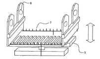
図2に基板ホルダー保持装置Aの斜視図を示す。
基板ホルダー保持装置Aは、基板ホルダー8を並置して保持する可動式テーブル(第1の保持機構および列方向駆動手段に相当)5と、可動式テーブル5に保持される基板ホルダー8の全てを一度に可動式テーブル5から分離するユニット7Aと7Bからなる分離機構(第2の保持機構に相当)7と、これらの動作をコントロールするコントローラ(連動機構に相当)6と、を備える。具体的には、可動式テーブル5は、複数の基板ホルダー8を保持可能なテーブル本体51と、テーブル本体51を駆動する駆動機構52と、を有する。テーブル本体51は、基板ホルダー8の底部に嵌め合う溝51aが複数等間隔に設けられていて、複数の基板ホルダー8を立て、基板ホルダーの板厚方向に配列させた状態で保持可能である。駆動機構52は、テーブル本体51を水平方向である前後方向に往復移動させるものである。本実施形態では、駆動機構52のアクチュエータは、ボールねじにより構成される。テーブル本体51に結合部分52aに結合されたナットを含み、該ナットはテーブル51の前後方向に延在するネジ軸に螺合している。ネジ軸はコントローラ6の制御下にモータの回転で回転される。ネジ軸の回転によりナットは前後に移動し、該ナットに結合されたテーブル51が前後に移動される。なお、駆動機構52のアクチュエータは、ボールねじに限定されず、エアシリンダや油圧シリンダなどのシリンダ、後述の搬送機構20と同様に磁気結合を介して直動させるマグネットアクチュエータなどを用いてもよい。FIG. 2 is a perspective view of the substrate holder holding device A.
The substrate holder holding device A includes a movable table (corresponding to the first holding mechanism and the column direction driving means) 5 that holds the
また、分離機構7は、本実施形態では、可動式テーブル5の左右両側に配されるユニット7A,7Bから構成される。ユニット7Aは、基板ホルダー8の底部を保持可能な保持部71Aと、保持部71Aを上下方向に駆動する駆動部72Aと、を有する。
保持部71Aは、基板ホルダー8の列方向に延びる水平部711aと、水平部711aから上下方向に延び、基板ホルダー8の列方向に沿って所定の間隔で複数配される区画部材712aと、を有する。区画部材712aによって区切られる1つの区画に、1枚の基板ホルダー8を保持する。従って、この区画の配置間隔は、可動式テーブル5の溝51aの間隔と同じ大きさであり、可動式テーブル5に保持される複数の基板ホルダー8の全てを同時に保持部71Aが保持可能に構成されている。また、分離機構7の保持部71Aに形成される区画数は、本実施形態では、搬送機構20による1回の搬送数分(例えば、可動式テーブル5の溝数よりも1つ分)だけ少ない数以上に設定されている。In addition, the
The holding
分離機構7の保持部71Aを上下移動させる駆動部72Aは、油圧シリンダなどの直動アクチュエータを備えて構成される。なお、図示していないが、直動アクチュエータは基板ホルダー収納チャンバ18の外に配され、駆動軸のみがチャンバ内に配されている。もう一方のユニット7Bも7Aと同じ構成である。
テーブル5上の基板ホルダーの全部を一度に上方に持ち上げテーブルから離させる分離機構7は、基板ホルダー8を可動式テーブル5に保持させるときは、図2に示すようにテーブル5の下方の退避位置にあり、可動式テーブル5から基板ホルダーを分離させるときは図3に示すように上方に駆動され、各ユニット7A、7Bが左右両側から持ち上げるようにして基板ホルダー8を可動式テーブル5から分離する。また、上方の位置から退避位置まで下降させるときに、基板ホルダー8を可動式テーブル5に移載する。The
When the
コントローラ6は、本実施形態では、一般的なコンピュータを有して構成され、プログラムに基づき可動式テーブル5、分離機構7、後述する搬送機構20及び移載機構30に指令を出力し、これらの協調した動作を実現する。なお、コントローラ6は基板ホルダー収納チャンバ18に配される複数の基板ホルダー保持装置Aに共通に設けられ、それぞれをコントロールする。 In this embodiment, the controller 6 includes a general computer, and outputs commands to the movable table 5, the
図4Aと図4Bに、基板ホルダー8、搬送機構20及び移載機構30を示す。図4Aは正面方向から見た基板ホルダー8及び搬送機構20の図であり、図4Bは基板の側方から見た基板ホルダー8、搬送機構20及び移載機構30の図である。 4A and 4B show the
基板ホルダー8は、本実施形態では、1枚又は複数枚(図では2枚)の基板81(搭載状態を破線で示す)を、真空チャンバ13内で両面に対して処理することができるように保持する。図4Aに示すように、基板ホルダー8は複数の支持爪83によって基板を側面から支持することで、表面全体への成膜処理等を可能にしている。また、基板ホルダー8の底部には基板面内に平行な方向に沿って延びるマグネット82が設けられており、搬送機構20に磁気結合することでマグネット82の延在する方向(横方向)に沿って基板ホルダーは搬送される。 In the present embodiment, the
搬送機構20は、テーブル5の最前列にある基板ホルダーが、可動式テーブル5から移載機構30(図4B)で取り出された後、取り出された基板ホルダーを更に搬送する機構である。搬送マグネット23と、モータなどの回転駆動力を発生する駆動源21と、駆動源21の回転を搬送マグネット23の軸の周りの回転に変換する回転方向変換機構22と、を搬送機構20は有する。搬送マグネット23は、基板ホルダーの移動方向に延びる部材であって、N極及びS極のマグネットがらせん状に配列されたものであり、これを軸を中心に回転させることでその軸に沿った方向に図4の移載機構によって搬送マグネット23の上に載せられ磁気的に結合した基板ホルダー8を横方向に搬送可能である。本実施形態では、テーブル5から取出された基板ホルダーを搬送する搬送機構20は、基板ホルダー収納チャンバ18に並列配置された基板ホルダー保持装置Aの近傍に、かつ、複数の基板ホルダー保持装置Aによって共用されるように設けられている。コントローラ6は、駆動源21に駆動信号を出力することで、搬送方向や搬送タイミング、搬送速度等をコントロールする。なお、図示していないが、本実施形態では駆動源21は基板ホルダー収納チャンバ18の外に設けられ、駆動軸がベローズ(図示せず)に囲まれた状態でチャンバ内に挿入されている。なお、本発明の適用において、搬送機構は磁気結合によるものに限られない。 The
また、図4Bの移載機構30は、搬送マグネット23の前方に設けられ、搬送ローラ31と、搬送ベース32と、駆動軸33と、シリンダなどの上下駆動用の駆動装置34と、を備えて構成される。搬送ローラ31は、図4Bに示すように、基板ホルダ−8の突出部84とその底面側で嵌め合うように係合し可動式テーブル側に向いており、複数の搬送ローラ31が基板ホルダー8の搬送方向に沿って設けられている。搬送ローラ31は、搬送方向に沿って基板ホルダー8を案内するように回転可能である。駆動装置34は、コントローラ6からの指令に基づいて搬送ローラ31を上下に駆動し、搬送ローラ31を基板ホルダー8に係合し又は非係合にして基板ホルダー8の可動テーブル5への移載動作を実現する。 4B is provided in front of the
具体的には、図5に示す待機位置から図6に示す位置に搬送ローラ31を上昇させることで、基板ホルダー8の突出部84を搬送ローラ31に係合させて基板ホルダー8を可動式テーブル5から上方向に取り出す。そして、図4Bに示すように、基板ホルダー8のマグネット82が搬送マグネット23に磁気的に結合する搬送位置まで下降させることで、基板ホルダー8を可動式テーブル5から搬送位置に移載する。搬送位置の基板ホルダーは、その後図4Aの搬送機構で横方向に搬送される。逆の動作により、搬送位置から可動式テーブル5への移載も可能である。 Specifically, by raising the
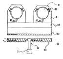
図7Aと7Bに基板ホルダー収納チャンバ18内の加熱機構(本実施形態ではヒータ4)の配置を示す。なお、図7Aは平面図、図7Bは側面図である。
ヒータ4は、脱ガス等を行うために基板ホルダー8を加熱可能なものであり、基板ホルダー8の上方に配置される。この位置は、分離機構7により基板ホルダー8を上方に配置した時に接触しない位置である。ヒータ4としては、例えば、輻射熱により基板ホルダー8を加熱可能なランプヒーターなどのほか、気体の加熱を介して基板ホルダー8を加熱するシーズヒータなども用いることができる。加熱するときは、上記分離機構7により基板ホルダー8を上昇させ、ヒータ4により近づけた状態とすると、より高い加熱効果が得られる。
なお、ヒータ4の代わりに又はこれと併用して、高温ガスを導入することによる基板ホルダー8の加熱も可能である。加熱時のチャンバー圧力状態に関しては、加圧、大気、真空状態での加熱が可能である。7A and 7B show the arrangement of the heating mechanism (
The
The
[基板ホルダー搬送の動作]
次に、上記構成の基板ホルダー保持装置A、搬送機構20および移載機構30の動作について説明する。
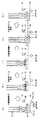
図8は、基板ホルダー収納チャンバ18から外へ基板ホルダー8を搬出するフローを示している。上述のような一連の動作、可動式テーブル5、分離機構7、搬送機構20及び移載機構30の動作をプログラムしたコントローラ6によりコントロールすることにより実現する。なお、図面を分かりやすくするために、図8では分離機構7については説明に必要な部分にのみ図示している。[Operation of substrate holder transport]
Next, operations of the substrate holder holding device A, the
FIG. 8 shows a flow for carrying the
図8−図11の実施例にあっては、テーブル5は前後方向(図面上は左右方向)に移動し、分離機構7は上下方向に移動し、移載機構30は上下方向及び前後方向に移動し、そして搬送マグネット23は固定位置(回転するが)であることに注意されたい。従って、これら機構の相対的移動の位置関係は、搬送マグネット23を基準として見ることができる。 8-11, the table 5 moves in the front-rear direction (left-right direction in the drawing), the
図8の前半(a)〜(f)は、1つの基板ホルダー8を可動式テーブル5から搬送位置H0、W0に移載し、搬出する動作である。
(a)は可動式テーブル5に基板ホルダー8が収容された状態を示す。この状態で可動式テーブル5を作動させ、搬送マグネット23側に前進させる((b))。このときの移動ピッチは、本実施形態では、可動式テーブル5における基板ホルダー8の配置間隔pと同じに設定されている。したがって、このピッチだけ動かしたときにちょうど搬送マグネット23の上方に最前列の基板ホルダー8が位置するように、可動式テーブル5と搬送マグネット23との位置関係を設定しておく。The first half (a) to (f) of FIG. 8 is an operation of transferring one
(A) shows the state in which the
次に、移載機構30を上方に移動させ搬送ローラ31を上昇させ、基板ホルダー8を可動式テーブル5から上方に取り出し((c))、この状態から可動式テーブル5を後退させる((d))。その後移載機構を下方に移動させ搬送ローラ31を下降させることで、基板ホルダー8を搬送位置H0,W0に移載する((e))。その後、搬送マグネット23を回転駆動し、基板ホルダー8を横方向に搬送して、収納チャンバ18から外へと搬出する((f))。これにより、可動式テーブル5の最前列溝、即ち搬送マグネット23側端部の配置スペースに1つ空きスペースができる。 Next, the
図8の後半(g)〜(k)は、上記可動式テーブル5の空いたスペースに基板ホルダー8を移す動作である。
移載機構30を上方に移動し移載位置から待機位置に戻し((g))、可動式テーブル5を上述と同じように配置間隔p分だけ搬送マグネット23側に前進させる((h))。そして、分離機構7を作動させ、可動式テーブル5に保持される全ての基板ホルダー8を上方に持ち上げ、可動式テーブル5から分離する((i))。その分離したままの状態で、可動式テーブル5を配置間隔p分だけ後退させた後((j))、分離機構7を下降させ基板ホルダー8を可動式テーブル5に移す。これにより、基板ホルダー8が前述の空いたスペースを埋めて、搬送マグネット23側に詰めた状態で可動式テーブル5に配置される((k))。The latter half (g) to (k) of FIG. 8 is an operation of moving the
The
以後、(a)〜(k)を繰り返すことで、可動式テーブル5に配された全ての基板ホルダー8を順次収納チャンバから搬出することが可能である。
以上のように、本発明の搬送方式により、放射状ではなく並列状での基板ホルダー8の収納が可能となる。又、複数あった搬送レールを1箇所の可動式テーブル5とする事で、可動式テーブル上の基板ホルダーを小間隔収納でき、チャンバーサイズの小型化が可能となる。同時に搬送用部品の削減によるコストダウンと、搬送ローラー位置の調整作業時間を大幅に縮小できる。Thereafter, by repeating (a) to (k), it is possible to sequentially carry out all the
As described above, according to the transport method of the present invention, it is possible to store the
又、基板ホルダー8の配置面積が縮小する事で、全ホルダーをカバーする脱ガス用ヒーター4配置が可能となる。同時にホルダー当りの入熱量が上がり昇温時間等の短縮が計れる。又、基板ホルダー8と可動式テーブル5の分離機構により、基板ホルダー8とヒータ4を近づけることで昇温時間短縮も可能となる。 Further, since the arrangement area of the
[変形例]
なお、本実施形態では、可動式テーブル5の移動ピッチを常に基板ホルダー8の配置間隔p分にしているが、可動式テーブル5と搬送位置の間で基板ホルダー8を移載するときと、分離機構7を用いて可動式テーブル5内で基板ホルダー8の配置を変えるときとで、移動ピッチを変えてもよい。つまり、可動式テーブル5内で配置を変えるときは配置間隔p単位で移動ピッチを設定することが必要であるが、搬送位置に移載する場合は搬送レール23の位置まで可動式テーブル5を動かすことが必要である。[Modification]
In the present embodiment, the moving pitch of the movable table 5 is always set to the arrangement interval p of the
また、上記シーケンスに限られない。例えば、図9に可動式テーブル5内で基板ホルダー8の配置を換える際の別の動作例を示す。図9の例では、図8の(g)に対応する(g’)の状態から、可動式テーブル5を駆動する前に分離機構7により基板ホルダー8を分離し(h’)、その状態で可動式テーブル5を搬送位置とは反対の方向に駆動し(i’)、基板ホルダー8を可動式テーブル5に移す(j’)。図8の(k)の状態に図9の(k’)が対応している。この場合、図8の動作例に比べ、反対方向に駆動する分スペースが必要となるが、搬送マグネット23との干渉は避けられる。 Moreover, it is not restricted to the said sequence. For example, FIG. 9 shows another operation example when the arrangement of the
また、図9の例のように、分離機構7を用いるタイミングと可動式テーブル5を動かすタイミングによって、可動式テーブル5の駆動方向を変えることができることから、タイミングを変えることで、基板ホルダー8を搬出でなく可動式テーブル5に搬入する場合にも搬出時と駆動方向を揃えることができる。 Moreover, since the driving direction of the movable table 5 can be changed according to the timing of using the
これを適用した搬入時の動作例を図10に示す。図10(a)は、搬送機構20の搬送位置によりテーブル5の最前列溝に基板ホルダー8が搬送されている状態である。搬入時は、搬出時とは異なり、可動式テーブル5を駆動する前に分離機構7を動作させて、基板ホルダー8を分離することで((b))、搬送マグネット23側(前方)に可動式テーブル5を駆動させて最前列に搬送した基板ホルダーを2列目に移し替え行うことができる((c)、(d)、(e))。搬送機構20からテーブルの最前列に基板ホルダーは搬送され、その基板ホルダーは分離機構7とにより順次後方に送られる。こうしてテーブル5の全ての溝に基板ホルダーを搬入できる。これにより、可動式テーブル5が移動するスペースを最小限に抑えることができる。もちろん、同様のタイミング調整により搬入時、搬送時共に搬送マグネット側23とは反対方向に駆動するようにしてもよいし、タイミング調整を行わず、搬入時と搬出時とで反対方向に駆動するようにしてもよい。 FIG. 10 shows an operation example at the time of loading to which this is applied. FIG. 10A shows a state where the
また、基板ホルダー8を縦置きする場合について説明したが、例えば上下方向に積層する場合(この場合、列方向は上下方向となる)にも本発明を適用可能である。また、上記実施形態では、基板の板厚方向に基板ホルダー8を積層させているが、基板の側面方向(面内方向)に積層させてもよい。 Moreover, although the case where the
また、上記実施形態では、可動式テーブル5を1配置間隔p分ずつ進退させているが、これに限らず、例えば、2配置間隔p分又はそれ以上ずつずらすようにしてもよい。例えば、搬送機構20が1度に2個ずつ搬送するような場合は、2個ずつ空きスペースができるので、これを一気につめることができるように基板ホルダー8が搬送される配置間隔p分ずつ(この例では2配置間隔p分ずつ)、進退させてもよい。もちろん、1配置間隔pを2回繰り返して、つめてもよい。 In the above-described embodiment, the movable table 5 is advanced and retracted by one arrangement interval p. However, the present invention is not limited to this. For example, the movable table 5 may be shifted by two arrangement intervals p or more. For example, when the
また、上記実施形態では、保持機構からの分離機能と列方向への駆動とを各保持機構に分けて行わせているが、一方の保持機構に双方を行わせてもよい。例えば、可動式テーブル5を上下方向にも駆動し、分離機構7の保持部材71Aを可動式テーブル5の下方に固定し、可動式テーブル5を下降させることで分離機構7へ基板ホルダー8を移し、可動式テーブル5が前進又は交代した後、保持部材71Aを上昇させることで再び可動式テーブル5に移すような構成としてもよい。この場合、例えば、上記可動式テーブル5の駆動機構52の下方に、さらにシリンダなどの上下駆動装置を設け、駆動機構52ごと動かすようにする。 In the above-described embodiment, the separation function from the holding mechanism and the driving in the column direction are performed separately for each holding mechanism, but one holding mechanism may perform both. For example, the movable table 5 is also driven in the vertical direction, the holding
また、上記実施形態では、一方の保持機構(可動式テーブル5)のみ、列方向に駆動する構成としているが、第2の保持機構にも駆動機構を設けて、第1及び第2の保持機構の両方を交互に列方向に進退させるような構成としてもよい。
また、上記基板ホルダー収納チャンバ―は、基板ホルダー8の真空保管、脱ガスのために用いているが、これに限らず、基板の脱ガスや隣室へ導入まで待機させる目的で、基板が搭載された状態の基板ホルダー8を収納する装置として使用してもよい。In the above embodiment, only one holding mechanism (movable table 5) is driven in the row direction. However, the second holding mechanism is also provided with a driving mechanism, and the first and second holding mechanisms are provided. Both may be configured to alternately advance and retract in the column direction.
The substrate holder storage chamber is used for vacuum storage and degassing of the
また、上記実施形態では、可動式テーブル5を動かすことで、可動式テーブル5内の基板ホルダー8の列方向位置を変更する構成としているが、図11(a)に示すように、可動式テーブル5を動かすことで、分離機構7における基板ホルダー8の列方向配置を変更するようにしてもよい。この動作は、図11に示すように、動作シーケンスを変更するだけで実現可能である。図11は、基板ホルダー8搬出時に搬送マグネット23側に詰める場合のシーケンス例を示す。なお、この場合、可動式テーブル5の最大保持可能数(溝51a数)を分離機構7における最大保持可能数よりも小さく(搬送機構20による1回の搬送数分だけ小さく)することが好ましい。また、列方向に駆動する可動式テーブルの列方向長さを短くできるので、更なる省スペース化が可能である。 Moreover, in the said embodiment, it is set as the structure which changes the row direction position of the board |
Claims (5)
Translated fromJapanese前記上下機構により基板を前記テーブル機構から分離している間に前記テーブル機構を前記配列方向に移動させた後、前記上下機構から移動したテーブル機構に基板ホルダを移載することにより前記テーブル機構における基板ホルダーの位置を移動させる、該テーブル機構と該上下機構を連動して制御するコントローラとを備え、
該基板ホルダー保持装置が複数並列に配されていることを特徴とする基板ホルダー収納チャンバ。It can holdas columns juxtaposed a plurality of substrate holder and movable table mechanism to the array directionof the substrate holder, andhas a holding member capable of holding the substrate holder,the holding of the substrate holderby vertical movementAsubstrate holder holding device comprisinga vertical mechanismcapable of transferring a substrate holderheld by a member and separatedand separated from the table mechanism to the table mechanism, and while thesubstrate is separated from the table mechanism by the vertical mechanismThe table mechanism and the vertical mechanism move the position of the substrate holder in the table mechanismby moving the table mechanism in the arrangement direction and then transferring the substrate holder to the table mechanism moved from the verticalmechanism. With a controller that controls
Substrate holder housing chamber, characterized inthatsaid substrate holder holding devicesare arranged in parallel a plurality.
基板ホルダーをチャンバ外へ搬出するための搬送機構と、
前記テーブル機構の端部に保持される基板ホルダーを取り出し、前記搬送機構に移載する移載機構と、
を備えることを特徴とする請求項1に記載の基板ホルダー収納チャンバ。The substrate holder holding device;
A transport mechanism for carrying the substrate holder out of the chamber;
A transfer mechanism that takes out the substrate holder held at the end of the table mechanism and transfers it to the transport mechanism;
The substrate holder storage chamber according to claim1 , further comprising:
前記搬送手段は、前記基板ホルダーの向きを変更することなく基板ホルダーを搬送可能に構成されていることを特徴とする請求項2に記載の基板ホルダー収納チャンバ。In the substrate holder holding device, the table mechanism arranges and holds a plurality of substrate holders along the front direction of the substrate holder,
The substrate holder storage chamber according to claim2 , wherein the transfer unit is configured to be able to transfer the substrate holder without changing the orientation of the substrate holder.
前記基板ホルダーに基板を搭載させるステップと、
前記基板ホルダーに搭載された基板に表面処理を施すステップと、を備えることを特徴とする磁気ディスクの製造方法。Removing the substrate holder stored in the substrate holder storage chamber according to claim 1 from the substrate holder storage chamber;
Mounting a substrate on the substrate holder;
And a step of subjecting the substrate mounted on the substrate holder to a surface treatment.
Applications Claiming Priority (1)
| Application Number | Priority Date | Filing Date | Title |
|---|---|---|---|
| PCT/JP2008/067737WO2010038272A1 (en) | 2008-09-30 | 2008-09-30 | Substrate holder holding apparatus and substrate holder storing chamber |
Related Child Applications (1)
| Application Number | Title | Priority Date | Filing Date |
|---|---|---|---|
| JP2009168891ADivisionJP5150575B2 (en) | 2009-07-17 | 2009-07-17 | Substrate holder holding device and substrate holder storage chamber |
Publications (2)
| Publication Number | Publication Date |
|---|---|
| JP4377452B1true JP4377452B1 (en) | 2009-12-02 |
| JPWO2010038272A1 JPWO2010038272A1 (en) | 2012-02-23 |
Family
ID=41459723
Family Applications (1)
| Application Number | Title | Priority Date | Filing Date |
|---|---|---|---|
| JP2009510222AActiveJP4377452B1 (en) | 2008-09-30 | 2008-09-30 | Substrate holder storage chamber, inline-type substrate processing apparatus, and magnetic disk manufacturing method |
Country Status (4)
| Country | Link |
|---|---|
| US (2) | US20100129539A1 (en) |
| JP (1) | JP4377452B1 (en) |
| CN (1) | CN101828259B (en) |
| WO (1) | WO2010038272A1 (en) |
Cited By (1)
| Publication number | Priority date | Publication date | Assignee | Title |
|---|---|---|---|---|
| US9200362B2 (en) | 2010-07-09 | 2015-12-01 | Canon Anelva Corporation | Substrate holder stocker device, substrate processing apparatus, and substrate holder moving method using the substrate holder stocker device |
Families Citing this family (4)
| Publication number | Priority date | Publication date | Assignee | Title |
|---|---|---|---|---|
| WO2012067085A1 (en)* | 2010-11-15 | 2012-05-24 | 株式会社アルバック | Film-forming apparatus |
| CN104986573B (en)* | 2015-05-28 | 2017-03-08 | 合肥京东方光电科技有限公司 | Carrier for carrying substrates |
| CN108465620B (en)* | 2018-05-30 | 2023-09-12 | 赛迈科先进材料股份有限公司 | Special bracket for high-performance large-specification isostatic pressing graphite high-pressure impregnation |
| US11133207B2 (en)* | 2018-08-30 | 2021-09-28 | Taiwan Semiconductor Manufacturing Co., Ltd. | Method for forming films on wafers separated by different distances |
Family Cites Families (11)
| Publication number | Priority date | Publication date | Assignee | Title |
|---|---|---|---|---|
| JPS6359137A (en) | 1986-08-29 | 1988-03-15 | Canon Inc | Communication system |
| JPH01316457A (en) | 1988-06-17 | 1989-12-21 | Canon Inc | Holder exchange device |
| JPH0356668A (en) | 1989-07-24 | 1991-03-12 | Ricoh Co Ltd | Sputtering device |
| US5203445A (en) | 1990-03-17 | 1993-04-20 | Tokyo Electron Sagami Limited | Carrier conveying apparatus |
| JP2987148B1 (en) | 1999-01-26 | 1999-12-06 | 国際電気株式会社 | Substrate processing equipment |
| JP4526151B2 (en)* | 2000-01-28 | 2010-08-18 | キヤノンアネルバ株式会社 | Substrate transfer device for substrate processing apparatus |
| US6228429B1 (en)* | 2000-02-01 | 2001-05-08 | Intevac, Inc. | Methods and apparatus for processing insulating substrates |
| US6919001B2 (en)* | 2000-05-01 | 2005-07-19 | Intevac, Inc. | Disk coating system |
| JP4222589B2 (en)* | 2001-03-26 | 2009-02-12 | キヤノンアネルバ株式会社 | Substrate transport apparatus and substrate processing apparatus using the same |
| DE10119229B4 (en)* | 2001-04-19 | 2004-04-15 | Rohwedder Microtech Gmbh & Co. Kg | Workpiece carrier changing device and method for changing workpiece carriers |
| JP4447279B2 (en) | 2003-10-15 | 2010-04-07 | キヤノンアネルバ株式会社 | Deposition equipment |
- 2008
- 2008-09-30CNCN2008800254890Apatent/CN101828259B/enactiveActive
- 2008-09-30WOPCT/JP2008/067737patent/WO2010038272A1/ennot_activeCeased
- 2008-09-30JPJP2009510222Apatent/JP4377452B1/enactiveActive
- 2009
- 2009-11-24USUS12/624,944patent/US20100129539A1/ennot_activeAbandoned
- 2011
- 2011-03-23USUS13/069,453patent/US9997386B2/enactiveActive
Cited By (1)
| Publication number | Priority date | Publication date | Assignee | Title |
|---|---|---|---|---|
| US9200362B2 (en) | 2010-07-09 | 2015-12-01 | Canon Anelva Corporation | Substrate holder stocker device, substrate processing apparatus, and substrate holder moving method using the substrate holder stocker device |
Also Published As
| Publication number | Publication date |
|---|---|
| US9997386B2 (en) | 2018-06-12 |
| JPWO2010038272A1 (en) | 2012-02-23 |
| US20100129539A1 (en) | 2010-05-27 |
| US20110168086A1 (en) | 2011-07-14 |
| CN101828259B (en) | 2012-06-27 |
| CN101828259A (en) | 2010-09-08 |
| WO2010038272A1 (en) | 2010-04-08 |
Similar Documents
| Publication | Publication Date | Title |
|---|---|---|
| JP5582895B2 (en) | Substrate holder stocker apparatus, substrate processing apparatus, and substrate holder moving method using the substrate holder stocker apparatus | |
| JP4377452B1 (en) | Substrate holder storage chamber, inline-type substrate processing apparatus, and magnetic disk manufacturing method | |
| JP5274339B2 (en) | Substrate processing apparatus and substrate transfer method | |
| JP5330721B2 (en) | Processing apparatus and processing method | |
| TWI533398B (en) | Substrate support instrument, and vertical heat treatment apparatus and driving method thereof | |
| CN110626798B (en) | A modular turntable device | |
| CN102763210B (en) | Base plate processing system and substrate convey method | |
| JP2007298270A (en) | Steel plate heating furnace | |
| JP2007242648A (en) | Substrate processing apparatus | |
| KR101669685B1 (en) | Processing apparatus and processing method | |
| CN101126000A (en) | heat welding method | |
| TW559980B (en) | Substrate feed chamber and substrate processing apparatus | |
| JP5150575B2 (en) | Substrate holder holding device and substrate holder storage chamber | |
| JP5795174B2 (en) | Substrate transfer device | |
| KR101649299B1 (en) | Wafer processing system having linear wafer transfering apparatus | |
| JP2010225652A (en) | Substrate transfer device | |
| JPS62136439A (en) | Plate takeout device | |
| JP4451901B2 (en) | Transport device | |
| KR102430242B1 (en) | Apparatus for moving cassette racks on the in line chamber | |
| CN101471267A (en) | Chip assembly device | |
| JP2005145713A (en) | Substrate transfer device | |
| JP3592694B2 (en) | Semiconductor manufacturing apparatus, wafer transfer method in semiconductor manufacturing apparatus, and semiconductor element manufacturing method | |
| JPS61263533A (en) | Semiconductor transfer apparatus | |
| KR101717815B1 (en) | Casette pick-up unit and Deposition system having the same | |
| JP4595887B2 (en) | Magazine processing / collection equipment |
Legal Events
| Date | Code | Title | Description |
|---|---|---|---|
| TRDD | Decision of grant or rejection written | ||
| A01 | Written decision to grant a patent or to grant a registration (utility model) | Free format text:JAPANESE INTERMEDIATE CODE: A01 Effective date:20090812 | |
| A01 | Written decision to grant a patent or to grant a registration (utility model) | Free format text:JAPANESE INTERMEDIATE CODE: A01 | |
| A61 | First payment of annual fees (during grant procedure) | Free format text:JAPANESE INTERMEDIATE CODE: A61 Effective date:20090910 | |
| R150 | Certificate of patent or registration of utility model | Ref document number:4377452 Country of ref document:JP Free format text:JAPANESE INTERMEDIATE CODE: R150 Free format text:JAPANESE INTERMEDIATE CODE: R150 | |
| FPAY | Renewal fee payment (event date is renewal date of database) | Free format text:PAYMENT UNTIL: 20120918 Year of fee payment:3 | |
| FPAY | Renewal fee payment (event date is renewal date of database) | Free format text:PAYMENT UNTIL: 20120918 Year of fee payment:3 | |
| FPAY | Renewal fee payment (event date is renewal date of database) | Free format text:PAYMENT UNTIL: 20130918 Year of fee payment:4 | |
| R250 | Receipt of annual fees | Free format text:JAPANESE INTERMEDIATE CODE: R250 | |
| R250 | Receipt of annual fees | Free format text:JAPANESE INTERMEDIATE CODE: R250 | |
| R250 | Receipt of annual fees | Free format text:JAPANESE INTERMEDIATE CODE: R250 | |
| R250 | Receipt of annual fees | Free format text:JAPANESE INTERMEDIATE CODE: R250 | |
| R250 | Receipt of annual fees | Free format text:JAPANESE INTERMEDIATE CODE: R250 | |
| R250 | Receipt of annual fees | Free format text:JAPANESE INTERMEDIATE CODE: R250 | |
| R250 | Receipt of annual fees | Free format text:JAPANESE INTERMEDIATE CODE: R250 | |
| R250 | Receipt of annual fees | Free format text:JAPANESE INTERMEDIATE CODE: R250 | |
| R250 | Receipt of annual fees | Free format text:JAPANESE INTERMEDIATE CODE: R250 | |
| R250 | Receipt of annual fees | Free format text:JAPANESE INTERMEDIATE CODE: R250 | |
| R250 | Receipt of annual fees | Free format text:JAPANESE INTERMEDIATE CODE: R250 | |
| R250 | Receipt of annual fees | Free format text:JAPANESE INTERMEDIATE CODE: R250 | |
| R250 | Receipt of annual fees | Free format text:JAPANESE INTERMEDIATE CODE: R250 | |
| R250 | Receipt of annual fees | Free format text:JAPANESE INTERMEDIATE CODE: R250 |