JP4376329B2 - Apparatus for detecting a predetermined pattern in a data stream, method for detecting a predetermined pattern in a data stream, and method in a network interface for identifying a predetermined pattern in a data packet - Google Patents
Apparatus for detecting a predetermined pattern in a data stream, method for detecting a predetermined pattern in a data stream, and method in a network interface for identifying a predetermined pattern in a data packetDownload PDFInfo
- Publication number
- JP4376329B2 JP4376329B2JP13006898AJP13006898AJP4376329B2JP 4376329 B2JP4376329 B2JP 4376329B2JP 13006898 AJP13006898 AJP 13006898AJP 13006898 AJP13006898 AJP 13006898AJP 4376329 B2JP4376329 B2JP 4376329B2
- Authority
- JP
- Japan
- Prior art keywords
- pattern
- data
- field
- entry
- bytes
- Prior art date
- Legal status (The legal status is an assumption and is not a legal conclusion. Google has not performed a legal analysis and makes no representation as to the accuracy of the status listed.)
- Expired - Lifetime
Links
Images


Classifications
- H—ELECTRICITY
- H04—ELECTRIC COMMUNICATION TECHNIQUE
- H04L—TRANSMISSION OF DIGITAL INFORMATION, e.g. TELEGRAPHIC COMMUNICATION
- H04L12/00—Data switching networks
- H04L12/02—Details
- H04L12/12—Arrangements for remote connection or disconnection of substations or of equipment thereof
- G—PHYSICS
- G06—COMPUTING OR CALCULATING; COUNTING
- G06F—ELECTRIC DIGITAL DATA PROCESSING
- G06F7/00—Methods or arrangements for processing data by operating upon the order or content of the data handled
- G06F7/02—Comparing digital values
- G—PHYSICS
- G06—COMPUTING OR CALCULATING; COUNTING
- G06F—ELECTRIC DIGITAL DATA PROCESSING
- G06F2207/00—Indexing scheme relating to methods or arrangements for processing data by operating upon the order or content of the data handled
- G06F2207/02—Indexing scheme relating to groups G06F7/02 - G06F7/026
- G06F2207/025—String search, i.e. pattern matching, e.g. find identical word or best match in a string
- Y—GENERAL TAGGING OF NEW TECHNOLOGICAL DEVELOPMENTS; GENERAL TAGGING OF CROSS-SECTIONAL TECHNOLOGIES SPANNING OVER SEVERAL SECTIONS OF THE IPC; TECHNICAL SUBJECTS COVERED BY FORMER USPC CROSS-REFERENCE ART COLLECTIONS [XRACs] AND DIGESTS
- Y02—TECHNOLOGIES OR APPLICATIONS FOR MITIGATION OR ADAPTATION AGAINST CLIMATE CHANGE
- Y02D—CLIMATE CHANGE MITIGATION TECHNOLOGIES IN INFORMATION AND COMMUNICATION TECHNOLOGIES [ICT], I.E. INFORMATION AND COMMUNICATION TECHNOLOGIES AIMING AT THE REDUCTION OF THEIR OWN ENERGY USE
- Y02D30/00—Reducing energy consumption in communication networks
- Y02D30/50—Reducing energy consumption in communication networks in wire-line communication networks, e.g. low power modes or reduced link rate
Landscapes
- Engineering & Computer Science (AREA)
- Theoretical Computer Science (AREA)
- General Physics & Mathematics (AREA)
- Physics & Mathematics (AREA)
- Mathematical Analysis (AREA)
- Pure & Applied Mathematics (AREA)
- Mathematical Optimization (AREA)
- General Engineering & Computer Science (AREA)
- Computational Mathematics (AREA)
- Computer Networks & Wireless Communication (AREA)
- Signal Processing (AREA)
- Power Sources (AREA)
- Computer And Data Communications (AREA)
- Small-Scale Networks (AREA)
- Data Exchanges In Wide-Area Networks (AREA)
Description
Translated fromJapanese【0001】
【技術分野】
この発明はパターン認識に関し、特に、データストリームにおける所定のパターンを検出するのに用いるためにネットワークワークステーション内のメモリにパターンデータを記憶するための配列に関する。
【0002】
【関連技術の説明】
現在、ワークステーションコンピュータは電力節約機構を含むように設計されており、ここでワークステーションコンピュータは所定の期間活動停止した後閉鎖するものである。
【0003】
電力節約機構のある提案はワークステーションコンピュータのためのウェイクアップルーチンを明記し、ここで、イーサネット型またはIEEE802.3ネットワークのようなネットワークに対するネットワークインターフェイスがネットワークからデータパケットを受信するための電力を維持する。所定のパターンを有したデータパケットを受信すると、ネットワークインターフェイスはワークステーションコンピュータに「ウェイクアップ」させ、たとえば、遠隔ワークステーションによって要求される所定の動作を行なわせる。
【0004】
このタイプのウェイクアップスキームを実施する際に遭遇する問題は、ネットワークインターフェイス装置があるパターンのデータを認識可能である必要があることである。パターンは典型的には、所定のパターンにマッチしなければならない受信されたデータパケット内の特定バイトと、パターン認識には関連がなく、したがって無視されるべきである他のデータバイトとから構成される。可能な解決策の1つは、受信されるデータパケットと同一のパターンを有するデータバイトのシーケンスをメモリに記憶することであり、ここでバイトごとの比較が記憶されたデータと受信されたパケットデータとの間で行なわれる。しかしながら、このような配列には、メモリに記憶された関連のない(すなわち、ドントケア)バイトからパターン比較における関連のあるバイトを比較ハードウェアが区別できるようにするためにさらなるオーバーヘッドが必要であるという欠点がある。さらに、受信されたデータパケットが、ドントケアとして無視されるかなり多数のバイトを含み得るので、受信されたデータパケットにおいて無視されるバイトに対応するナルデータのメモリへの記憶にはメモリ空間のかなりの浪費が伴う。
【0005】
【発明の概要】
複数個の関連のないデータバイトを有するデータストリームにおける所定のパターンの検出を可能にし、検出されるべきパターンのために必要な記憶空間を最小にする配列が必要である。
【0006】
また、パターンデータを記憶するために最小量のメモリを用いて、受信されたデータストリームと多数の所定のパターンとを同時に比較可能にする配列が必要である。
【0007】
また、所定のパターンの検出に関連のないデータバイトをデータストリームから選択的に放棄することによって、データストリームにおける所定のパターンを効率的に検出する配列が必要である。
【0008】
また、検出されるべきパターン内に複数個の関連のないデータバイトを有するデータストリームとの比較のためにメモリ内でパターンデータを圧縮するための配列が必要である。
【0009】
これらおよび他の要求がこの発明によって達成され、ここで、無視されるべき、データストリームのデータバイトを識別する対応のデータフィールドに基づいて、データストリームとパターンメモリに記憶されたパターンデータとの比較の間にデータストリームからのデータバイトのグループが選択的に放棄される。
【0010】
この発明の1つの局面に従うと、データストリームにおける所定のパターンを検出するための装置は、所定のパターンの少なくとも一部を特定するパターンエントリを記憶するように構成されたパターンメモリを含み、パターンエントリは、パターンデータフィールドと、パターンデータフィールドとの比較の前に無視されるべき、データストリームにおけるいくつかのバイトを特定する第2のフィールドとを含み、この装置はさらに、第2のフィールドに基づいてパターンデータフィールドとデータストリームのバイトの選択された隣接するグループとを比較し、比較結果を出力するための比較器を含む。各パターンエントリにおける第2のフィールドは、比較器がパターンデータフィールドとの比較の前にデータストリームにおけるいくつかのバイトを選択的に無視することを可能にし、パターンメモリにおけるナルデータ値の必要性を最小にする。したがって、パターンメモリに記憶されるパターンの大きさはほぼ50%縮小され得る。
【0011】
この発明の別の局面はデータストリームにおける所定のパターンを検出するための方法であって、所定のパターンに対応するシーケンスを有した複数個のパターンエントリをメモリに記憶するステップを含み、各パターンエントリは、所定のパターンに対応するパターンバイトを記憶するパターンデータフィールドと、第2のフィールド値を記憶する第2のフィールドとを含み、さらに、データストリームを受信するステップと、受信されたデータストリームの開始位置に基づいてパターンエントリの選択された1つを読出すステップと、対応の1つのパターンエントリの第2のフィールドに基づいてデータストリームから隣接するデータバイトの少なくとも1つのグループを選択的に放棄するステップと、その1つのパターンエントリからのパターンバイトと、選択的に放棄されたグループに隣接し、それに続く、データストリームからのデータバイトの第2のグループとを比較し、比較結果を出力するステップと、それぞれのパターンエントリのために検出された比較結果に基づいてデータストリームにおける所定のパターンを検出するステップとを含む、方法を提供する。検出されるべき所定のパターンに対応するシーケンスにおけるパターンエントリの記憶と、対応のパターンエントリのフィールドに基づいてデータストリームから隣接するデータバイトのグループを選択的に放棄することとによって、メモリ内で所定のパターンを特定するのに必要なパターンエントリの数が最小にされる。
【0012】
この発明のさらに別の局面は、データパケットにおける所定のパターンを識別するためのネットワークインターフェイスにおける方法であって、パケット交換網から媒体アクセス制御装置によってデータパケットを受信するステップと、受信されたデータパケットにおいて所定のパターンを検出するステップとを含み、検出するステップは、(1)受信されたデータパケットの開始位置に基づいて、所定のパターンに対応する所定のシーケンスを有した複数個のパターンエントリを記憶するメモリから選択されたパターンエントリを読出すステップと、(2)選択されたパターンエントリにおけるスキップフィールドに基づいてデータパケットからデータバイトのグループを選択的にラッチするステップと、(3)選択されたパターンエントリに対する比較結果を得るために、選択されたパターンエントリにおける対応のマスクビットに基づいて、データパケットからのデータバイトのラッチされたグループと選択されたパターンエントリにおけるパターンデータとを選択的に比較するステップと、(4)所定のパターンを検出するために、所定のシーケンスとデータバイトの隣接するグループとに対して、それぞれのパターンエントリのための比較結果を累積するステップとを含む、方法を提供する。スキップフィールドに基づくデータパケットからのデータバイトのグループの選択的なラッチングは、受信されたデータパケットにおける関連のあるバイトとメモリに記憶されたパターンエントリとの間の効率的な比較を可能にする。さらに、受信されたデータパケットの開始位置に基づく選択されたパターンエントリの読出によって、複数のパターン検出スキームが同時に実行可能となる。したがって、所定のデータパターンを記憶するための最小量の記憶空間で、受信されたデータパケットは複数の所定のデータパターンと同時に比較され得る。
【0013】
この発明のさらなる目的、利点および新規な特徴は以下の説明に一部記載され、一部以下の説明を吟味して当業者に明らかとなるか、またはこの発明を実行することによって学ばれ得る。この発明の目的および利点は前掲の特許請求の範囲に特定的に指摘される装置および組合せによって実現および達成できる。
【0014】
添付の図面が参照され、ここで、同じ参照符号を有するエレメントは全体を通して同じエレメントを表わす。
【0015】
【発明を実行するためのベストモード】
この発明は、イーサネット(IEEE802.3)ネットワークのようなパケット交換網におけるネットワークインターフェイスの例とともに説明される。ネットワークインターフェイスアーキテクチャを初めに説明し、次に、受信されたデータパケットにおける所定のパターンを検出するための配列が従う。しかしながら、この発明は他のネットワークインターフェイスシステムにも適用可能であることが明らかとなるであろう。
【0016】
ネットワークインターフェイスアーキテクチャ
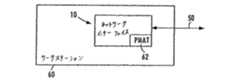
図1は、この発明の実施例に従うイーサネット(ANSI/IEEE802.3)ネットワークの媒体にアクセスする例示的ネットワークインターフェイス10のブロック図である。
【0017】
ネットワークインターフェイス10、好ましくは単一チップの32ビットイーサネット制御装置はコンピュータのローカルバス12、たとえば周辺コンポーネント相互接続(PCI)ローカルバスとイーサネットベースの媒体50との間のインターフェイスを与える。
【0018】
インターフェイス10はPCIバスインターフェイス装置16、バッファメモリ部18、およびネットワークインターフェイス部20を含む。PCIバスインターフェイス装置16はPCIスレーブインターフェイス16aおよびDMAインターフェイス16bを含む。スレーブインターフェイス16aは、PCI状態レジスタの読出およびプログラミングを含むPCI制御および状態情報を管理するが、ホストCPUとのPCIバスを介するスレーブ転送を管理するように構成されてもよい。DMAインターフェイス16bはネットワークインターフェイス10によるシステムメモリへ、かつそこからのDMA転送を管理する。したがって、PCIバスインターフェイス装置16はスレーブおよび/またはマスタ(たとえばDMA)モードにおいてPCI転送を行なうように選択的に構成され得る。
【0019】
メモリ部18はネットワークインターフェイスチップ10上で直接実現される16ビットSRAMを含む。開示される実施例に従うと、SRAM18は先入先出(FIFO)制御装置22の制御の下ランダムアクセスの態様でアクセスされてもよく、または、それぞれ受信経路および送信経路のために受信部18aおよび送信部18bへと分割されてもよい。
【0020】
ネットワークインターフェイス10は、DMAインターフェイス16bを介するDMA転送を管理するように構成されたバッファ管理装置24も含む。バッファ管理装置24は、開始アドレス、長さ等を特定する、ホストメモリ内のDMAディスクリプタに基づいてDMA転送を管理する。バッファ管理装置24は、命令をPCIバスサイクルへと変換するDMAインターフェイス16bへと命令を出すことによって、システムメモリから伝送バッファ18bへのDMA読出を開始する。したがって、バッファ管理装置24は、DMA転送のためのディスクリプタ管理と、メモリ部18からのデータの記憶および読出に関連したポインタとを含む。バッファ管理装置24およびメモリ制御装置22が別個の構成要素として示されるが、2つの装置はメモリ装置18へ、かつそこからのデータのすべての転送を制御するメモリ管理装置を形成するために統合されてもよい。
【0021】
ネットワークインターフェイス20は、媒体アクセス制御(MAC)コア26と、汎用直列インターフェイス(GPSI)28と、外部の10Mb/sまたは100Mb/s物理(PHY)トランシーバに接続するための媒体独立インターフェイス(MII)30と、外部アドレス検出インターフェイス(EADI)32と、マンチェスタエンコーダおよびデコーダを有する付加装置インターフェイス(AUI)34と、10/100Mb/sツイストペアトランシーバ媒体付加装置(MAU)36とを含む。
【0022】
ネットワークインターフェイス10はまた、MIIポート30を介してMIIバス上で2つの装置間のMIIハンドシェイクを行なうように構成されたネットワークポート管理装置38を含む。このようなMIIハンドシェイクは、リンク情報と、管理データクロック(MDC)を用いるMII層でのプログラミング情報と、管理データ入力/出力(MDIO)経路とを含み得る。
【0023】
自動否定部40は、リンクパートナーが10Mb/s、100Mb/sで動作可能であるか、かつ、リンクが半二重であるべきかまたは全二重であるべきかを示すデータを交換するために、PHY層上でリンクパートナーとのIEEEコンプライアントネゴシエーションを行なう。
【0024】
LED制御装置44は、内部デコーディング論理およびネットワークインターフェイス状態レジスタ(図示せず)に基づいて、LED出力信号の発生を選択的に制御する。ネットワークインターフェイス10はまた、IEEE1149.1コンプライアントJTAG境界スキャンテストアクセスポートインターフェイス36を含む。
【0025】
EEPROMインターフェイス42は、ネットワークインターフェイスアダプタカード上または直列インターフェイスリンクを介してホストコンピュータのマザーボート上でEEPROMに接続する。EEPROM(図1に示さず)はネットワークインターフェイスに関連した構成情報でプログラミングされ、ネットワークインターフェイスがEEPROMインターフェイス42を介して初期化の間に構成されることを可能にする。一旦初期化されると、ネットワークインターフェイスは内部レジスタ(図示せず)に構成情報を記憶し、ホストコンピュータがパワーダウンされる場合にネットワークインターフェイスをホストコンピュータとは独立して動作可能にさせる。したがって、ネットワークインターフェイスはホストコンピュータがスタンバイモードにある間に動作するよう構成でき、それによって、ネットワークインターフェイスはホストコンピュータ内の論理にパワーアップ情報を出力することが可能となり、それによって、ホストコンピュータは、ネットワークから受信され、かつ後述の特定のプロトコルを有するデータパケットに応答して自動的にターンオン可能となる。
【0026】
データストリームにおける所定のパターンの検出
図2は、活動停止の期間の間自動的に閉鎖し、後述の所定のパターンを有するネットワークインターフェイス10によってデータパケットが受信されると自動的に再開始するよう構成されたホストコンピュータ60のためのネットワークインターフェイス10を示すブロック図である。
【0027】
図2に示すように、ネットワークインターフェイス10は、ネットワーク媒体50から受信されたデータパケットから複数個の所定のパターンの1つを検出するように構成されたパターンマッチング回路(PMAT)62を含む。さまざまな電力管理スキームが、受信されたデータパケットに識別されるパターンに依存して種々のウェイクアップ動作を行なうために用いられる得る。
【0028】
図3は、受信されたデータパケットのための異なった3つのパターンシーケンス64を示す。たとえば、マイクロソフト・コーポレイション(Microsoft Corporation )によって示される電力管理パケットの1つのタイプは第1のパターンシーケンス64aを含み、ここで、ワード9および10における最後の4つのバイトがインターネットプロトコルに特定的なバイトであり、特定のデータパターンバイトが電力管理パケットのワード3および5に見られる。パターンシーケンス64bは代替的な所定のパターンを特定し、ここで、受信されたデータパケットの最初の6つのバイトが値「AD」(16進法)を含み、ワード3、7および8が所定のデータ値を含む。同様のパターンがパターン64cに関して説明される。
【0029】
開示される実施例に従うと、所定のパターン64a、64bおよび64cに関連したパターンデータは、対応のパターンデータフィールドとの比較の前に無視されるべき、データストリームにおけるいくつかのバイトを特定するフィールドをパターンメモリに記憶することによって圧縮される。図4は、所定のパターンの少なくとも一部を特定する、パターンメモリに記憶されるパターンエントリの構造を示す。パターンエントリ66は4バイトのパターンデータフィールド70、4ビットのマスクフィールド72、3ビットのスキップフィールド74、および1ビットのエンドフィールド76を含む。エンドフィールド76およびスキップフィールド74はそれぞれ最後/無視カウント(L/I)フィールドとして図3に示される。スキップフィールド74(すなわち、無視カウントフィールド)は、パターンデータフィールドとの比較の前に無視されるべき、データストリームにおけるいくつかのバイトを特定する。たとえば、図3の所定のパターン64aはワード3の最初の2つのバイト(たとえば、08/06)に所定のパターンデータを有し、したがって、パターン63aに従う電力管理パケットのワード0、1および2はパターン比較の目的のために無視され得る関連のないドントケアデータを含む。ナル値でパターンメモリの空間を浪費するのではなく、開示される実施例はパターンエントリ66aの最初のパターンエントリ(すなわち、ワード0)をスキップフィールド74に「3」の値を有するように設定する。したがって、スキップフィールド74(無視カウントフィールド)の値「3」は、パターン64aの最初の3つのワード(ワード0、ワード1およびワード2)がストリーム64aのワード3におけるデータバイトの次の隣接するグループとの比較の前に無視されるべきであることを示す。
【0030】
パターン64aに対応するパターンエントリ66aの次のパターンエントリ(たとえば、ワード1)が次にパターンメモリから読出される。次のパターンエントリ(ワード1)のスキップフィールド74は1の値を有し、データバイトの1つのグループ(たとえば、パターン64aのワード4)が、パターンデータフィールド「xx 01 xx xx」との比較のためにパターンストリームからのデータバイトの次の隣接するグループ(たとえば、ワード5)とのマッチングの前にスキップまたは放棄されるべきことを示す。
【0031】
したがって、スキップ/無視フィールド74は、対応のパターンエントリのためのスキップ/無視フィールドの値に基づいて比較器がデータストリーム64から隣接するデータバイトの少なくとも1つのグループを選択的に放棄可能にする。
【0032】
図3および図4に示すように、パターンエントリ66は、パターンデータフィールド70と比較されるバイトの対応のグループの選択されたバイトに対するドントケア条件を示す4ビットのマスクフィールド72を含む。たとえば、パターンエントリ66aのワード1はパターン「xx 01 xx xx」を含み、対応のマスクフィールドは値「1011」を有する。「1」のマスク値が無視条件に対応し、「0」のマスク値が対応のバイトのための比較条件に対応する。したがって、マスクフィールドパターン「1011」は、第2のパターンデータバイト「01」のみがデータストリームの対応のバイトと比較されるべきであり、かつ残りの3つのデータバイトが比較において無視されるべきであることを示す。したがって、開示される配列は、所定のシーケンスに配列された複数個のパターンエントリ66がメモリ内の空間の量を最小にしながら所定のパターンを表わすことを可能にする。3ビットのスキップフィールド74は最大で総数7つのワード(28バイト)を比較を行なう前にスキップ可能にする。効果的な比較は3つのパターン64a、64bおよび64cの大きさをパターンデータの168バイトから92バイトに縮小し、45%の縮小を行なうことが可能である。
【0033】
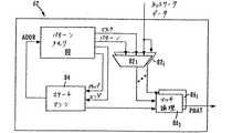
図5は、この発明の実施例に従ってデータストリームにおける所定のパターン66を検出するための図2のパターンマッチ回路62を示すブロック図である。パターンマッチ回路62は、メモリ内の必要とされる空間の量を最小にするためにスキップ/無視フィールド74を用いることによってそれぞれのパターンを特定する図3のパターンエントリ66を記憶するように構成されたパターンメモリ80を含む。パターンマッチ回路62はまた、記憶されたパターンエントリ66の選択された1つのパターンデータフィールド70と図1の媒体アクセス制御装置(MAC)から供給されたパケットデータストリームからのバイトの選択されたグループとを比較するための少なくとも1つの比較器82を含む。図5に示すように、パターンマッチ回路は、受信されたデータパケットとパターンメモリ80に記憶されたそれぞれの所定のパターンとの同時の比較を可能にする複数個の比較器82iを含み得る。したがって、パターン66a、66bおよび66cの各々はそれぞれの比較器82iを用いて受信されたデータパケットと同時に比較できる。開示される実施例に従うと、パケットデータはMACから1クロック当り1ニブル(4ビット)のデータ速度で供給され、したがって、8クロックサイクルが比較器で単一のバイトを受信するために必要である。したがって、パターンメモリ80から対応の比較器82へとマスクおよびパターンデータを転送するのに1クロックサイクルかかると仮定すると、パターンマッチ回路62は32の同時の4バイト比較を行なうことができる。
【0034】
パターンマッチ回路62はまた、選択されたパターンエントリのパターンエントリデータ(たとえば、パターンデータフィールドおよびマスクフィールド)の適切な比較器82iへの供給を制御するように構成されたステートマシン84を含む。ステートマシンはパターンメモリ80に記憶された制御エントリに基づいてパターンエントリ68を選択的にアドレス指定する。各制御エントリは、特定のパターンが比較のために能動化されるか、また第1の対応のパターンエントリ68の開始位置(たとえば、ワード0)を特定する。ステートマシン84は、MACからの入力データクロックと同期したクロック信号に基づいて、かつそれぞれのスキップフィールド74と最後のパターンエントリにおけるパターン比較の終りを特定するエンドビット76とに対して、比較の進行を追跡する。
【0035】
パターンマッチ回路62はまた、比較器82iから比較結果を受取るマッチ論理86を含む。マッチ論理86はパターンエントリの1つにおけるエンドフィールド86に設定されたエンドビットに基づいて比較結果の終りを判断する。後述するように、マッチ論理86は比較器82からの比較結果における非マッチ結果の存在を判断するために比較結果を監視する。マッチ論理86は、非マッチ結果の存在を判断する前に、パターンエントリの1つにおけるエンドフィールドの検出に応答して所定のパターンの検出を示す信号を出力する。図3に示すように、エンド信号はステートマシン84からストローブとして供給され得る。代替的に、エンドフィールドはパターンメモリ80から直接マッチ論理86に供給されてもよい。さらに、マッチ論理はマッチを有する対応のパターンに依存して種々のタイプのマッチ結果を出力してもよい。
【0036】
図4は、パターンデータとパケットデータからの入力データストリームとの間の比較をマスクフィールド72からのマスクビットについてより詳細に示す。たとえば、図4は、フィールド70のパターンデータとネットワークデータパケットからのデータストリームとをバイトごとに比較するように構成された比較器の1つ820を示す。たとえば、パターンデータフィールドのバイト0がバイト比較器8200においてデータストリームの対応のバイトと比較され、パターンデータのバイト1がバイト比較器8201において入力データストリームの対応のバイトと比較され、以下同様である。各バイト比較器8201は比較結果を出力する8ビットの比較器90と、比較結果とマスクフィールド72からの対応のマスクビットとを受取るORゲート92とを含む。したがって、対応のマスクビットが1に設定されるならば、マスクビットは、対応の比較結果にかかわらず、対応の選択されたデータバイトのための比較結果として出力される。4ビットの比較結果(C0-3)がマッチ論理86に出力され、ここで、値Cはマッチまたはドントケア条件では1に等しく、Cはマッチがない場合のみ0に等しい。
【0037】
図6は、この発明の実施例に従って媒体アクセス制御装置からのデータストリームにおける所定のパターンを検出するための方法のブロック図である。この方法はネットワークインターフェイスの初期化で始まり、ここで、ホストコンピュータはたとえば活動停止の期間の後にスタンバイ状態にパワーダウンされ得る。上述のように、ネットワークインターフェイス10はワークステーション60から独立して動作するために別個の電力供給構成を有する。
【0038】
検出のための実際の方法は、媒体アクセス制御装置からのデータクロックに同期化し、フレームの開始を識別することによってステップ100で始まる。特に、パターン比較は受信されたデータパケットの開始位置に対して同期化される。当該技術において認められるように、データパケットの状態はパケットの初めの開始フレーム区切り記号によって識別され得る。ステートマシン84は次にパターンメモリ80の制御エントリによって特定されるような次のパターンデータエントリ66を読出す。このように、ステートマシン84は、能動化されたパターンのための制御エントリにおける対応の開始アドレスに基づいて、フレームの開始を検出すると最初のパターンエントリを読出す。ステートマシンはまた内部スキップカウンタにスキップ/無視フィールド74の値をロードする。パターン比較のためのスキップカウンタはステートマシン84または代替的に各比較器82iに維持され得る。ステートマシンはパターンデータフィールド70およびマスクフィールド72を適切な比較器82iへとロードする。
【0039】
次に、パターンマッチ回路62がステップ104でパケットデータの次のワード(すなわち、4バイト)を各比較器82iへとロードする。ステップ106で対応の比較器82のためのスキップカウンタが0に等しくなければ、隣接するデータバイトのロードされたグループが対応の比較器82iから放棄され、スキップカウンタはステップ108で減分される。したがって、データバイトの4バイトのグループが、パターンデータフィールドとの比較の前に無視されるべき4バイトのグループの数を特定するスキップ/無視フィールド74に基づいて選択的に放棄され得る。
【0040】
ステップ106で対応の比較器82のためのスキップカウンタが0に等しければ、パケットデータのロードされた4つのバイトがステップ110で対応の比較器82iへとラッチされ、データのラッチされたグループがパターンエントリ66からの対応のパターンデータとバイトごとに図4に示すように比較される。比較器82iはステップ112でマスクフィールド72からの対応のマスクビットに基づいてバイト比較結果を出力する。ステートマシン84、または代替的に対応の比較器82iがステップ114で1に設定されたエンドフィールド76を検出すれば、パターンストローブの終りがステートマシン84または対応の比較器82iによってマッチ論理86に出力され、ステップ116でパターン比較の終了を示す。
【0041】
図7は、マッチ論理86の観点からパターンマッチングのための方法を示すブロック図である。マッチ論理86はたとえばMACからのフレーム開始指示に応答してステップ120でマッチフラグを1にリセットする。次に、マッチ論理86は対応の比較器82iから比較結果(C0-3)を受取り、ステップ122で比較結果ビットのいずれかが0に等しいかを調べる。比較結果ビットのいずれかが非マッチ検出を示す0に等しければ、マッチ論理86はステップ124でマッチフラグを0に等しく設定する。次に、マッチ論理86はステップ126でパターンストローブの終りがステートマシン84または対応の比較器82iから受取られたかを判断する。パターンストローブの終りがマッチ論理86によって受取られていなければ、マッチ論理は次の比較結果のいずれかが0値を有するかを判断し続ける。ステップ126でパターンストローブの終りを検出すると、マッチ論理はステップ128でマッチフラグがなお1に設定されているかを調べる。マッチフラグがステップ128で1になお設定されていれば、マッチ論理86はステップ130で1に等しいパターンマッチ信号を出力し、マッチした特定のパターンを特定する情報を含み得る。
【0042】
開示される実施例に従うと、データストリームにおける所定のパターンを検出するための配列は、記憶されたパターンデータフィールドとの比較の前に無視され得るデータストリームにおけるいくつかのバイトを特定するスキップ/無視フィールドを含むことによってパターンメモリ内でパターンデータを圧縮する。比較動作におけるスキップ/無視フィールドはデータストリームの開始と同期化され、最小の論理またはメモリ空間を用いて同時のパターン比較を並列して可能にする。
【0043】
開示される配列がネットワークに接続されるワークステーションのためのウェイクアップ論理に関して所定のパターンを検出することについて説明されたが、所定のパターンを検出するための配列は同期データストリームのための他のパターン認識スキームにも適用可能であることが認識されるであろう。
この発明は目下最も実用的であり、かつ好ましい実施例と考えられるものと関連して説明されたが、この発明は開示された実施例に限定されず、前掲の特許請求の範囲の精神および範疇内に含まれるさまざまな変更および等価な配列に及ぶものと考えられることを理解されたい。
【図面の簡単な説明】
【図1】この発明の実施例に従う、データパケットを受信するために用いられ得る例示的ネットワークインターフェイスを示すブロック図である。
【図2】図1のネットワークインターフェイスと、ホストコンピュータワークステーション、ネットワーク、およびウェイクアップ手順のために用いられるパターンマッチング回路との関係を示す図である。
【図3】この発明の実施例に従う、受信されたデータパケットとパターンメモリ内に記憶されたパターンエントリとの間の比較を示す図である。
【図4】パターンエントリとパターン比較器との間の関係を示す図である。
【図5】この発明の実施例に従う図2のパターンマッチング回路を示すブロック図である。
【図6】図5のステートマシンの観点からデータパケットにおける所定のパターンを識別するための方法を示す図である。
【図7】図5のマッチ論理の観点からデータパケットにおける所定のパターンを識別するための方法を示す図である。
【符号の説明】
10 ネットワークインターフェイス
12 ローカルバス
16 PCIバイパスインターフェイス装置
18 バッファメモリ部[0001]
【Technical field】
The present invention relates to pattern recognition, and more particularly to an arrangement for storing pattern data in memory within a network workstation for use in detecting a predetermined pattern in a data stream.
[0002]
[Description of related technology]
Currently, workstation computers are designed to include a power saving mechanism, where the workstation computer shuts down after a period of inactivity.
[0003]
One proposal for a power saving mechanism specifies a wake-up routine for a workstation computer, where a network interface to a network, such as an Ethernet or IEEE 802.3 network, maintains power to receive data packets from the network. To do. Upon receipt of a data packet having a predetermined pattern, the network interface causes the workstation computer to “wake up” and perform, for example, a predetermined operation requested by the remote workstation.
[0004]
A problem encountered when implementing this type of wake-up scheme is that the network interface device needs to be able to recognize some pattern of data. A pattern typically consists of a specific byte in a received data packet that must match a given pattern and other data bytes that are not relevant to pattern recognition and therefore should be ignored. The One possible solution is to store in memory a sequence of data bytes having the same pattern as the received data packet, where the byte-by-byte comparison is stored and the received packet data Between. However, such an array requires additional overhead to allow the comparison hardware to distinguish relevant bytes in pattern comparisons from unrelated (ie don't care) bytes stored in memory. There are drawbacks. In addition, since the received data packet may contain a significant number of bytes that are ignored as don't care, the storage of null data in memory corresponding to the ignored bytes in the received data packet is significant in memory space. It involves waste.
[0005]
SUMMARY OF THE INVENTION
There is a need for an arrangement that allows detection of a predetermined pattern in a data stream having a plurality of unrelated data bytes and minimizes the storage space required for the pattern to be detected.
[0006]
There is also a need for an arrangement that allows a received data stream to be compared simultaneously with a number of predetermined patterns using a minimum amount of memory to store pattern data.
[0007]
There is also a need for an arrangement that efficiently detects a predetermined pattern in a data stream by selectively abandoning data bytes unrelated to detection of the predetermined pattern from the data stream.
[0008]
There is also a need for an arrangement for compressing pattern data in memory for comparison with a data stream having a plurality of unrelated data bytes in the pattern to be detected.
[0009]
These and other requirements are achieved by the present invention, where a comparison between the data stream and the pattern data stored in the pattern memory is based on the corresponding data field that identifies the data bytes of the data stream to be ignored. During this time, groups of data bytes from the data stream are selectively discarded.
[0010]
According to one aspect of the present invention, an apparatus for detecting a predetermined pattern in a data stream includes a pattern memory configured to store a pattern entry that identifies at least a portion of the predetermined pattern, the pattern entry Includes a pattern data field and a second field that identifies some bytes in the data stream to be ignored prior to comparison with the pattern data field, the apparatus further based on the second field A comparator for comparing the pattern data field with a selected adjacent group of bytes of the data stream and outputting a comparison result. The second field in each pattern entry allows the comparator to selectively ignore some bytes in the data stream prior to comparison with the pattern data field, eliminating the need for null data values in the pattern memory. Minimize. Therefore, the size of the pattern stored in the pattern memory can be reduced by almost 50%.
[0011]
Another aspect of the present invention is a method for detecting a predetermined pattern in a data stream, comprising storing a plurality of pattern entries having a sequence corresponding to the predetermined pattern in a memory, each pattern entry Includes a pattern data field that stores a pattern byte corresponding to a predetermined pattern, and a second field that stores a second field value, and further includes the steps of receiving a data stream, Reading a selected one of the pattern entries based on the starting position and selectively discarding at least one group of adjacent data bytes from the data stream based on the second field of the corresponding one pattern entry And a single pattern entry Comparing the pattern byte with the second group of data bytes from the data stream that is adjacent to the selectively abandoned group and subsequently outputting the comparison result and detection for each pattern entry Detecting a predetermined pattern in the data stream based on the compared results obtained. Predetermining in memory by storing pattern entries in a sequence corresponding to a predetermined pattern to be detected and selectively discarding a group of adjacent data bytes from the data stream based on the field of the corresponding pattern entry The number of pattern entries required to identify the pattern is minimized.
[0012]
Yet another aspect of the present invention is a method at a network interface for identifying a predetermined pattern in a data packet, the step of receiving a data packet from a packet switched network by a medium access controller, and the received data packet Detecting a predetermined pattern in step (1), wherein the detecting step includes: (1) selecting a plurality of pattern entries having a predetermined sequence corresponding to the predetermined pattern based on a start position of the received data packet; Reading a selected pattern entry from a memory to store; (2) selectively latching a group of data bytes from a data packet based on a skip field in the selected pattern entry; and (3) selected Pattern entry Selectively comparing the latched group of data bytes from the data packet with the pattern data in the selected pattern entry based on the corresponding mask bits in the selected pattern entry to obtain a comparison result for And (4) accumulating comparison results for each pattern entry against a predetermined sequence and adjacent groups of data bytes to detect the predetermined pattern. . Selective latching of a group of data bytes from a data packet based on a skip field allows an efficient comparison between relevant bytes in the received data packet and pattern entries stored in memory. In addition, multiple pattern detection schemes can be performed simultaneously by reading selected pattern entries based on the start position of the received data packet. Thus, received data packets can be compared simultaneously with a plurality of predetermined data patterns with a minimum amount of storage space for storing the predetermined data patterns.
[0013]
Additional objects, advantages and novel features of the invention will be set forth in part in the description which follows, and in part will be apparent to those skilled in the art upon examination of the description or may be learned by practice of the invention. The objects and advantages of the invention may be realized and attained by means of the instruments and combinations particularly pointed out in the appended claims.
[0014]
Reference is made to the accompanying drawings, wherein elements having the same reference numeral represent the same element throughout.
[0015]
Best mode for carrying out the invention
The present invention is described with an example of a network interface in a packet switched network such as an Ethernet (IEEE 802.3) network. The network interface architecture will be described first, followed by an arrangement for detecting a predetermined pattern in the received data packet. However, it will be apparent that the present invention is applicable to other network interface systems.
[0016]
Network interface architecture
FIG. 1 is a block diagram of an
[0017]
A
[0018]
The
[0019]
The
[0020]
The
[0021]
The
[0022]
The
[0023]
The automatic denial unit 40 exchanges data indicating whether the link partner is capable of operating at 10 Mb / s, 100 Mb / s, and whether the link should be half or full duplex , IEEE compliant negotiation with link partner on PHY layer.
[0024]
The LED controller 44 selectively controls the generation of LED output signals based on internal decoding logic and a network interface status register (not shown). The
[0025]
The EEPROM interface 42 connects to the EEPROM on a network interface adapter card or on a host computer motherboard via a serial interface link. The EEPROM (not shown in FIG. 1) is programmed with configuration information associated with the network interface, allowing the network interface to be configured during initialization via the EEPROM interface 42. Once initialized, the network interface stores configuration information in an internal register (not shown), allowing the network interface to operate independently of the host computer when the host computer is powered down. Thus, the network interface can be configured to operate while the host computer is in standby mode, thereby allowing the network interface to output power-up information to logic within the host computer, thereby allowing the host computer to It can be turned on automatically in response to a data packet received from the network and having a specific protocol described below.
[0026]
Detection of predetermined patterns in the data stream
2 for a
[0027]
As shown in FIG. 2, the
[0028]
FIG. 3 shows three
[0029]
According to the disclosed embodiment, the pattern data associated with a given
[0030]
The next pattern entry (eg, word 1) of pattern entry 66a corresponding to
[0031]
Accordingly, the skip / ignore
[0032]
As shown in FIGS. 3 and 4, the
[0033]
FIG. 5 is a block diagram illustrating the
[0034]
The
[0035]
The
[0036]
FIG. 4 shows the comparison between the pattern data and the input data stream from the packet data in more detail for the mask bits from the
[0037]
FIG. 6 is a block diagram of a method for detecting a predetermined pattern in a data stream from a medium access control device according to an embodiment of the present invention. This method begins with the initialization of the network interface, where the host computer can be powered down to a standby state, for example after a period of inactivity. As described above, the
[0038]
The actual method for detection begins at step 100 by synchronizing to the data clock from the media access controller and identifying the start of the frame. In particular, the pattern comparison is synchronized with the start position of the received data packet. As will be appreciated in the art, the state of the data packet can be identified by the initial frame delimiter at the beginning of the packet. The
[0039]
Next, the
[0040]
If the skip counter for the
[0041]
FIG. 7 is a block diagram illustrating a method for pattern matching from the perspective of match logic 86. The match logic 86 resets the match flag to 1 in
[0042]
In accordance with the disclosed embodiment, the sequence for detecting a predetermined pattern in the data stream is skip / ignore specifying some bytes in the data stream that can be ignored prior to comparison with the stored pattern data field. The pattern data is compressed in the pattern memory by including the field. The skip / ignore field in the compare operation is synchronized with the start of the data stream, allowing simultaneous pattern comparisons in parallel using minimal logic or memory space.
[0043]
Although the disclosed arrangement has been described for detecting a predetermined pattern with respect to wake-up logic for workstations connected to a network, the arrangement for detecting a predetermined pattern is different from that for synchronized data streams. It will be appreciated that the present invention is also applicable to pattern recognition schemes.
Although the invention has been described in connection with what is presently considered to be the most practical and preferred embodiments, the invention is not limited to the disclosed embodiments and is intended to be within the spirit and scope of the appended claims. It should be understood that the various modifications and equivalent arrangements contained within are considered to span.
[Brief description of the drawings]
FIG. 1 is a block diagram illustrating an exemplary network interface that may be used to receive data packets according to an embodiment of the present invention.
FIG. 2 is a diagram illustrating the relationship between the network interface of FIG. 1 and a host computer workstation, a network, and a pattern matching circuit used for wake-up procedures.
FIG. 3 is a diagram illustrating a comparison between a received data packet and a pattern entry stored in a pattern memory, in accordance with an embodiment of the present invention.
FIG. 4 is a diagram illustrating a relationship between a pattern entry and a pattern comparator.
5 is a block diagram showing the pattern matching circuit of FIG. 2 according to an embodiment of the present invention.
6 is a diagram illustrating a method for identifying a predetermined pattern in a data packet from the perspective of the state machine of FIG.
7 is a diagram illustrating a method for identifying a predetermined pattern in a data packet in terms of the match logic of FIG.
[Explanation of symbols]
10 Network interface
12 Local bus
16 PCI bypass interface device
18 Buffer memory section
Claims (20)
Translated fromJapanese前記所定のパターンの少なくとも一部を特定するパターンエントリを記憶するように構成されたパターンメモリを含み、前記パターンエントリは、パターンデータフィールドと、前記パターンデータフィールドとの比較の前に無視されるべきである、データストリームにおけるバイトの数を特定する第2のフィールドとを含み、さらに、
前記パターンデータフィールドと、前記第2のフィールドに基づいて選択された、前記データストリームの隣接するバイトのグループとを比較し、比較結果を出力するための比較器を含む、装置。An apparatus for detecting a predetermined pattern in a received data stream,
Including a pattern memory configured to store a pattern entry identifying at least a portion of the predetermined pattern, the pattern entry should be ignored before comparing the pattern data field with the pattern data field A second field specifyingthe number ofbytes in the data stream, and
An apparatus comprising: a comparator for comparing the pattern data field with a group of adjacent bytes of the data stream selected based on the second field and outputting a comparison result.
前記比較器は、対応のマスクフィールドに基づいて、対応の選択された隣接するバイトのグループの各々のために比較結果を発生する、請求項2に記載の装置。The pattern memory includes a plurality of the pattern entries for identifying a predetermined pattern from each of a plurality of selected groups of adjacent bytes, each of the pattern entries corresponding to the pattern data field. A mask field indicating don't care conditions for the selected bytes of the corresponding selected group of adjacent bytes;
The apparatus of claim 2, wherein the comparator generates a comparison result for each of a corresponding selected group of adjacent bytes based on a corresponding mask field.
に基づいて対応の所定のパターンを検出するためにパターンエントリのグループの1つを選択する、請求項5に記載の装置。The pattern memory stores a group of pattern entries and a control entry for each predetermined pattern, and the state machine stores a group of pattern entries to detect a corresponding predetermined pattern based on the control entry. The apparatus of claim 5, wherein one is selected.
前記所定のパターンに対応するシーケンスを有した複数個のパターンエントリをメモリに記憶するステップを含み、各パターンエントリは、前記所定のパターンに対応するパターンバイトを記憶するパターンデータフィールドと、第2のフィールド値を記憶する第2のフィールドとを含み、前記所定のパターンに対応するパターンバイトは、データバイトの第1のグループを形成し、さらに、
データストリームを受信するステップと、
受信されたデータストリームの開始位置に基づいて前記パターンエントリの選択された1つを読出すステップと、
対応の1つのパターンエントリの前記第2のフィールドに基づいて前記データストリームから隣接するデータバイトの少なくとも1つのグループを選択的に放棄するステップと、
1つのパターンエントリからのパターンバイトと、選択的に放棄されたグループに隣接し、それに続く、前記データストリームからのデータバイトの第2のグループとを比較し、比較結果を出力するステップと、
それぞれのパターンエントリのために検出された比較結果に基づいて前記データストリームにおける前記所定のパターンを検出するステップとを含む、方法。A method for detecting a predetermined pattern in a data stream by a pattern match circuit, comprising:
Storing a plurality of pattern entries having a sequence corresponding to the predetermined pattern in a memory, wherein each pattern entry includes a pattern data field for storing a pattern byte corresponding to the predetermined pattern; A pattern field corresponding to the predetermined pattern forms a first group of data bytes, and a second field storing field values;
Receiving a data stream;
Reading a selected one of the pattern entries based on a starting position of a received data stream;
Selectively discarding at least one group of adjacent data bytes from the data stream based on the second field of the corresponding one pattern entry;
Comparing a pattern byte from one pattern entry with a second group of data bytes from the data stream adjacent to and subsequently adjacent to the selectively abandoned group and outputting a comparison result;
Detecting the predetermined pattern in the data stream based on a comparison result detected for each pattern entry.
データバイトの第1のグループの前記パターンバイトの各々と、データバイトの第2のグループの対応の1つとを比較するステップと、
対応のパターンエントリに記憶された対応のマスクビットに基づいて前記各パターンバイトのために比較結果を選択的に出力するステップとを含む、請求項11に記載の方法。The comparing step includes:
Comparing each of the pattern bytes of the first group of data bytes with a corresponding one of the second group of data bytes;
12. The method of claim 11, comprising selectively outputting a comparison result for each pattern byte based on a corresponding mask bit stored in a corresponding pattern entry.
前記第2のフィールドの放棄値を識別するステップと、
放棄された値に基づいて隣接するデータバイトの少なくとも1つのグループを放棄するステップとを含み、放棄されたグループの数は前記放棄値に対応する、請求項13に記載の方法。The step of selectively abandoning comprises:
Identifying the abandonment value of the second field;
14. The method of claim 13, comprising: abandoning at least one group of adjacent data bytes based on an abandoned value, wherein the number of abandoned groups corresponds to the abandonment value.
パケット交換網から媒体アクセス制御装置によって前記データパケットを受信するステップと、
受信されたデータパケットにおいて前記所定のパターンを検出するステップとを含み、前記検出するステップは、
(1) 前記受信されたデータパケットの開始位置に基づいて、前記所定のパターンに対応する所定のシーケンスを有した複数個のパターンエントリを記憶するメモリから選択されたパターンエントリを読出すステップと、
(2) 前記選択されたパターンエントリにおけるスキップフィールドに基づいて前記データパケットからデータバイトのグループを選択的にラッチするステップと、
(3) 前記選択されたパターンエントリに対する比較結果を得るために、前記選択されたパターンエントリにおける対応のマスクビットに基づいて、前記データパケットからのデータバイトのラッチされたグループと前記選択されたパターンエントリにおけるパターンデータとを選択的に比較するステップと、
(4) 前記所定のパターンを検出するために、前記所定のシーケンスと隣接するデータバイトのグループとに対してそれぞれのパターンエントリのための比較結果を累積するステップとを含む、方法。A method at a network interface for identifying a predetermined pattern in a data packet by a pattern match circuit, comprising:
Receiving the data packet by a medium access controller from a packet switched network;
Detecting the predetermined pattern in the received data packet, the detecting step comprising:
(1) reading a selected pattern entry from a memory storing a plurality of pattern entries having a predetermined sequence corresponding to the predetermined pattern based on a start position of the received data packet;
(2) selectively latching a group of data bytes from the data packet based on a skip field in the selected pattern entry;
(3) A latched group of data bytes from the data packet and the selected pattern based on the corresponding mask bits in the selected pattern entry to obtain a comparison result for the selected pattern entry. Selectively comparing the pattern data in the entry;
(4) accumulating a comparison result for each pattern entry against the predetermined sequence and a group of adjacent data bytes to detect the predetermined pattern.
前記比較結果における非マッチ結果の存在を判断するステップと、
前記非マッチ結果の存在を判断する前に前記パターンエントリの1つにおけるエンドフィールドの検出に応答して前記所定のパターンの検出を示す信号を出力するステップとを含む、請求項16に記載の方法。The accumulating step includes
Determining the presence of a non-match result in the comparison result;
And outputting a signal indicating detection of the predetermined pattern in response to detection of an end field in one of the pattern entries prior to determining the presence of the non-match result. .
(1) 前記第2の所定のパターンのための第2の複数個のパターンエントリのための前記メモリから第2の選択されたパターンエントリを読出すステップと、
(2) 前記第2の選択されたパターンエントリの対応のスキップフィールドに基づいて前記データパケットからデータバイトの第2のグループを選択的にラッチするステップと、
(3) 前記第2の所定のパターンの検出のために、データバイトのラッチされた第2のグループと前記第2の選択されたパターンエントリにおけるパターンデータとを選択的に比較するステップとを含む、請求項19に記載の方法。Further comparing the received data packet simultaneously with the second predetermined pattern;
(1) reading a second selected pattern entry from the memory for a second plurality of pattern entries for the second predetermined pattern;
(2) selectively latching a second group of data bytes from the data packet based on a corresponding skip field of the second selected pattern entry;
(3) selectively comparing the latched second group of data bytes with the pattern data in the second selected pattern entry for detection of the second predetermined pattern. The method of claim 19.
Applications Claiming Priority (2)
| Application Number | Priority Date | Filing Date | Title |
|---|---|---|---|
| US08/961,023US6094443A (en) | 1997-10-30 | 1997-10-30 | Apparatus and method for detecting a prescribed pattern in a data stream by selectively skipping groups of nonrelevant data bytes |
| US08/961023 | 1997-10-30 |
Publications (2)
| Publication Number | Publication Date |
|---|---|
| JPH11143799A JPH11143799A (en) | 1999-05-28 |
| JP4376329B2true JP4376329B2 (en) | 2009-12-02 |
Family
ID=25503972
Family Applications (1)
| Application Number | Title | Priority Date | Filing Date |
|---|---|---|---|
| JP13006898AExpired - LifetimeJP4376329B2 (en) | 1997-10-30 | 1998-05-13 | Apparatus for detecting a predetermined pattern in a data stream, method for detecting a predetermined pattern in a data stream, and method in a network interface for identifying a predetermined pattern in a data packet |
Country Status (3)
| Country | Link |
|---|---|
| US (1) | US6094443A (en) |
| JP (1) | JP4376329B2 (en) |
| GB (1) | GB2330993B (en) |
Cited By (1)
| Publication number | Priority date | Publication date | Assignee | Title |
|---|---|---|---|---|
| WO2020092099A1 (en)* | 2018-10-29 | 2020-05-07 | Barefoot Networks, Inc. | Configuring and performing character pattern recognition in a data plane circuit |
Families Citing this family (29)
| Publication number | Priority date | Publication date | Assignee | Title |
|---|---|---|---|---|
| EP0919930B1 (en)* | 1997-11-26 | 2003-10-22 | Infineon Technologies AG | Method and apparatus for reading, modifying and writing data stored in a memory device |
| US7782844B1 (en)* | 1999-01-05 | 2010-08-24 | GlobalFoundries, Inc. | Method and apparatus for pattern matching on single and multiple pattern structures |
| US6704325B1 (en)* | 1999-04-06 | 2004-03-09 | 3Com Corporation | Method to recognize streaming memory aligned and non-memory aligned data patterns with optimal hardware reuse |
| US6317463B1 (en)* | 1999-06-14 | 2001-11-13 | Mitsubishi Electric Research Laboratories, Inc. | Method and apparatus for filtering data-streams |
| US6865222B1 (en)* | 1999-09-23 | 2005-03-08 | Texas Instruments Incorporated | Method and apparatus for testing a serial transmitter circuit |
| DE10016173A1 (en)* | 2000-03-31 | 2001-10-04 | Bosch Gmbh Robert | Bus station for an optical bus system |
| AUPR741401A0 (en)* | 2001-09-03 | 2001-09-20 | Guignard, Paul A. | Generic architecture for data exchange and data processing |
| EP1436936A4 (en)* | 2001-09-12 | 2006-08-02 | Safenet Inc | High speed data stream pattern recognition |
| US7003599B2 (en)* | 2001-10-24 | 2006-02-21 | Intel Corporation | Pipelined, universal serial bus parallel frame delineator and NRZI decoder |
| US7024526B2 (en)* | 2002-10-31 | 2006-04-04 | Hitachi, Ltd. | Apparatus and method of null data skip remote copy |
| JP3807379B2 (en)* | 2003-02-21 | 2006-08-09 | ソニー株式会社 | Pattern detection circuit |
| DE102004018556B4 (en) | 2004-04-14 | 2010-06-10 | Atmel Automotive Gmbh | Method for data communication between a base station and a transponder |
| US7706415B2 (en)* | 2004-07-29 | 2010-04-27 | Microsoft Corporation | Packet multiplexing multi-channel audio |
| US7574742B2 (en)* | 2004-11-15 | 2009-08-11 | Industrial Technology Research Institute | System and method of string matching for uniform data classification |
| US7359895B2 (en)* | 2004-11-18 | 2008-04-15 | Industrial Technology Research Institute | Spiral string matching method |
| US7398408B2 (en)* | 2004-11-24 | 2008-07-08 | Conexant Systems, Inc. | Systems and methods for waking up wireless LAN devices |
| DE102005044651A1 (en)* | 2005-09-19 | 2007-03-22 | Siemens Ag | Patient support device for radiotherapy |
| US8214672B2 (en) | 2009-01-07 | 2012-07-03 | Micron Technology, Inc. | Method and systems for power consumption management of a pattern-recognition processor |
| US9501705B2 (en) | 2009-12-15 | 2016-11-22 | Micron Technology, Inc. | Methods and apparatuses for reducing power consumption in a pattern recognition processor |
| EP2339778A1 (en)* | 2009-12-28 | 2011-06-29 | Nxp B.V. | Configuration of bus transceiver |
| US9716892B2 (en) | 2012-07-02 | 2017-07-25 | Qualcomm Incorporated | Video parameter set including session negotiation information |
| US9565437B2 (en) | 2013-04-08 | 2017-02-07 | Qualcomm Incorporated | Parameter set designs for video coding extensions |
| JP6160259B2 (en)* | 2013-05-30 | 2017-07-12 | 富士通株式会社 | Character string search method, character string search device, and character string search program |
| US9549196B2 (en)* | 2014-02-04 | 2017-01-17 | Microsoft Technology Licensing, Llc | Data unit identification for compressed video streams |
| US9854261B2 (en)* | 2015-01-06 | 2017-12-26 | Microsoft Technology Licensing, Llc. | Detecting markers in an encoded video signal |
| CN109863413B (en)* | 2016-05-20 | 2022-03-25 | 默升科技集团有限公司 | Scan-based test design in SERDES applications |
| US10007561B1 (en) | 2016-08-08 | 2018-06-26 | Bitmicro Networks, Inc. | Multi-mode device for flexible acceleration and storage provisioning |
| US12197510B2 (en)* | 2016-10-20 | 2025-01-14 | Micron Technology, Inc. | Traversal of S portion of a graph problem to be solved using automata processor |
| US10216596B1 (en)* | 2016-12-31 | 2019-02-26 | Bitmicro Networks, Inc. | Fast consistent write in a distributed system |
Family Cites Families (8)
| Publication number | Priority date | Publication date | Assignee | Title |
|---|---|---|---|---|
| US4242936A (en)* | 1979-09-14 | 1981-01-06 | Norlin Industries, Inc. | Automatic rhythm generator |
| US5483539A (en)* | 1990-11-07 | 1996-01-09 | Loral Aerospace Corp. | Programmable PCM/TDM demultiplexer |
| EP0601304B1 (en)* | 1992-10-14 | 1999-01-27 | Bayer Corporation | Method and apparatus for detecting bit sequences in data streams |
| US5557614A (en)* | 1993-12-22 | 1996-09-17 | Vlsi Technology, Inc. | Method and apparatus for framing data in a digital transmission line |
| US5557742A (en)* | 1994-03-07 | 1996-09-17 | Haystack Labs, Inc. | Method and system for detecting intrusion into and misuse of a data processing system |
| FR2718590B1 (en)* | 1994-04-12 | 1996-06-28 | Sgs Thomson Microelectronics | Method for detecting a pattern in a serial transmission. |
| US5590159A (en)* | 1995-02-07 | 1996-12-31 | Wandel & Goltermann Technologies, Inc. | Digital data sequence pattern filtering |
| US5982786A (en)* | 1997-11-21 | 1999-11-09 | Cypress Semiconductor Corp. | Circuits and methods for framing one or more data streams |
- 1997
- 1997-10-30USUS08/961,023patent/US6094443A/ennot_activeExpired - Lifetime
- 1998
- 1998-05-06GBGB9809584Apatent/GB2330993B/ennot_activeExpired - Fee Related
- 1998-05-13JPJP13006898Apatent/JP4376329B2/ennot_activeExpired - Lifetime
Cited By (1)
| Publication number | Priority date | Publication date | Assignee | Title |
|---|---|---|---|---|
| WO2020092099A1 (en)* | 2018-10-29 | 2020-05-07 | Barefoot Networks, Inc. | Configuring and performing character pattern recognition in a data plane circuit |
Also Published As
| Publication number | Publication date |
|---|---|
| US6094443A (en) | 2000-07-25 |
| JPH11143799A (en) | 1999-05-28 |
| GB2330993A (en) | 1999-05-05 |
| GB2330993B (en) | 1999-09-15 |
| GB9809584D0 (en) | 1998-07-01 |
Similar Documents
| Publication | Publication Date | Title |
|---|---|---|
| JP4376329B2 (en) | Apparatus for detecting a predetermined pattern in a data stream, method for detecting a predetermined pattern in a data stream, and method in a network interface for identifying a predetermined pattern in a data packet | |
| CN100473066C (en) | Simplified hardware network adapter and communication method | |
| US5752076A (en) | Dynamic programming of bus master channels by intelligent peripheral devices using communication packets | |
| US6105079A (en) | Apparatus and method in a network interface device for selectively supplying long bit information related to a data frame to a buffer memory and a read controller for initiation of data transfers | |
| US5594702A (en) | Multi-first-in-first-out memory circuit | |
| US6161160A (en) | Network interface device architecture for storing transmit and receive data in a random access buffer memory across independent clock domains | |
| US6625157B2 (en) | Apparatus and method in a network switch port for transferring data between buffer memory and transmit and receive state machines according to a prescribed interface protocol | |
| US6490280B1 (en) | Frame assembly in dequeuing block | |
| US6047001A (en) | Apparatus and method in a network interface device for storing a data frame and corresponding tracking information in a buffer memory | |
| US6985969B1 (en) | Receiving data on a networked computer in a reduced power state | |
| US6618390B1 (en) | Method and apparatus for maintaining randomly accessible free buffer information for a network switch | |
| JP3336816B2 (en) | Multimedia communication device and method | |
| US20030046457A1 (en) | Apparatus and method for an interface unit for data transfer between processing units in the asynchronous transfer mode | |
| WO2001037489A1 (en) | Receive filtering for communication interface | |
| US6577636B1 (en) | Decision making engine receiving and storing a portion of a data frame in order to perform a frame forwarding decision | |
| JP4129314B2 (en) | Network interface, device for initializing network interface, and method for loading configuration information in network interface | |
| US6154796A (en) | Apparatus and method in a network interface device for storing receiving frame status in a holding register | |
| US6061768A (en) | Apparatus and method in a network interface device for storing tracking information indicating stored data status between contending memory controllers | |
| EP1401155B1 (en) | Method and system for wakeup packet detection at gigabit speeds | |
| US6516371B1 (en) | Network interface device for accessing data stored in buffer memory locations defined by programmable read pointer information | |
| US6229817B1 (en) | System and method for programming late collision slot time | |
| US6904043B1 (en) | Apparatus and methods for storing and processing header information in a network switch | |
| US6574231B1 (en) | Method and apparatus for queuing data frames in a network switch port | |
| US6336156B1 (en) | Increased speed initialization using dynamic slot allocation | |
| US6473818B1 (en) | Apparatus and method in a network interface device for asynchronously generating SRAM full and empty flags using coded read and write pointer values |
Legal Events
| Date | Code | Title | Description |
|---|---|---|---|
| A621 | Written request for application examination | Free format text:JAPANESE INTERMEDIATE CODE: A621 Effective date:20050421 | |
| A131 | Notification of reasons for refusal | Free format text:JAPANESE INTERMEDIATE CODE: A131 Effective date:20080408 | |
| A601 | Written request for extension of time | Free format text:JAPANESE INTERMEDIATE CODE: A601 Effective date:20080707 | |
| A602 | Written permission of extension of time | Free format text:JAPANESE INTERMEDIATE CODE: A602 Effective date:20080710 | |
| A521 | Request for written amendment filed | Free format text:JAPANESE INTERMEDIATE CODE: A523 Effective date:20080807 | |
| A131 | Notification of reasons for refusal | Free format text:JAPANESE INTERMEDIATE CODE: A131 Effective date:20081028 | |
| A02 | Decision of refusal | Free format text:JAPANESE INTERMEDIATE CODE: A02 Effective date:20090217 | |
| A521 | Request for written amendment filed | Free format text:JAPANESE INTERMEDIATE CODE: A523 Effective date:20090612 | |
| A911 | Transfer to examiner for re-examination before appeal (zenchi) | Free format text:JAPANESE INTERMEDIATE CODE: A911 Effective date:20090622 | |
| TRDD | Decision of grant or rejection written | ||
| A01 | Written decision to grant a patent or to grant a registration (utility model) | Free format text:JAPANESE INTERMEDIATE CODE: A01 Effective date:20090825 | |
| A01 | Written decision to grant a patent or to grant a registration (utility model) | Free format text:JAPANESE INTERMEDIATE CODE: A01 | |
| A61 | First payment of annual fees (during grant procedure) | Free format text:JAPANESE INTERMEDIATE CODE: A61 Effective date:20090909 | |
| R150 | Certificate of patent or registration of utility model | Free format text:JAPANESE INTERMEDIATE CODE: R150 | |
| FPAY | Renewal fee payment (event date is renewal date of database) | Free format text:PAYMENT UNTIL: 20120918 Year of fee payment:3 | |
| FPAY | Renewal fee payment (event date is renewal date of database) | Free format text:PAYMENT UNTIL: 20120918 Year of fee payment:3 | |
| S111 | Request for change of ownership or part of ownership | Free format text:JAPANESE INTERMEDIATE CODE: R313113 | |
| FPAY | Renewal fee payment (event date is renewal date of database) | Free format text:PAYMENT UNTIL: 20120918 Year of fee payment:3 | |
| R350 | Written notification of registration of transfer | Free format text:JAPANESE INTERMEDIATE CODE: R350 |