JP4376150B2 - Rotation angle detector - Google Patents
Rotation angle detectorDownload PDFInfo
- Publication number
- JP4376150B2 JP4376150B2JP2004231636AJP2004231636AJP4376150B2JP 4376150 B2JP4376150 B2JP 4376150B2JP 2004231636 AJP2004231636 AJP 2004231636AJP 2004231636 AJP2004231636 AJP 2004231636AJP 4376150 B2JP4376150 B2JP 4376150B2
- Authority
- JP
- Japan
- Prior art keywords
- magnetic
- rotation angle
- rotation
- magnetic sensor
- magnet
- Prior art date
- Legal status (The legal status is an assumption and is not a legal conclusion. Google has not performed a legal analysis and makes no representation as to the accuracy of the status listed.)
- Expired - Fee Related
Links
- 238000001514detection methodMethods0.000claimsdescription60
- 230000004907fluxEffects0.000claimsdescription50
- 230000002093peripheral effectEffects0.000claimsdescription22
- 230000005389magnetismEffects0.000claimsdescription4
- 230000010363phase shiftEffects0.000claims1
- 230000003321amplificationEffects0.000description6
- 238000003199nucleic acid amplification methodMethods0.000description6
- 230000000694effectsEffects0.000description5
- 238000006073displacement reactionMethods0.000description4
- 239000000696magnetic materialSubstances0.000description3
- 230000035945sensitivityEffects0.000description3
- XEEYBQQBJWHFJM-UHFFFAOYSA-NIronChemical compound[Fe]XEEYBQQBJWHFJM-UHFFFAOYSA-N0.000description2
- 230000005415magnetizationEffects0.000description2
- 238000000034methodMethods0.000description2
- 230000000630rising effectEffects0.000description2
- 239000000758substrateSubstances0.000description2
- 238000010586diagramMethods0.000description1
- 230000007613environmental effectEffects0.000description1
- 230000001747exhibiting effectEffects0.000description1
- 229910052742ironInorganic materials0.000description1
- 230000007257malfunctionEffects0.000description1
- 239000002184metalSubstances0.000description1
- 229910052751metalInorganic materials0.000description1
- 230000004048modificationEffects0.000description1
- 238000012986modificationMethods0.000description1
Images


Classifications
- G—PHYSICS
- G01—MEASURING; TESTING
- G01D—MEASURING NOT SPECIALLY ADAPTED FOR A SPECIFIC VARIABLE; ARRANGEMENTS FOR MEASURING TWO OR MORE VARIABLES NOT COVERED IN A SINGLE OTHER SUBCLASS; TARIFF METERING APPARATUS; MEASURING OR TESTING NOT OTHERWISE PROVIDED FOR
- G01D5/00—Mechanical means for transferring the output of a sensing member; Means for converting the output of a sensing member to another variable where the form or nature of the sensing member does not constrain the means for converting; Transducers not specially adapted for a specific variable
- G01D5/12—Mechanical means for transferring the output of a sensing member; Means for converting the output of a sensing member to another variable where the form or nature of the sensing member does not constrain the means for converting; Transducers not specially adapted for a specific variable using electric or magnetic means
- G01D5/14—Mechanical means for transferring the output of a sensing member; Means for converting the output of a sensing member to another variable where the form or nature of the sensing member does not constrain the means for converting; Transducers not specially adapted for a specific variable using electric or magnetic means influencing the magnitude of a current or voltage
- G01D5/142—Mechanical means for transferring the output of a sensing member; Means for converting the output of a sensing member to another variable where the form or nature of the sensing member does not constrain the means for converting; Transducers not specially adapted for a specific variable using electric or magnetic means influencing the magnitude of a current or voltage using Hall-effect devices
- G01D5/145—Mechanical means for transferring the output of a sensing member; Means for converting the output of a sensing member to another variable where the form or nature of the sensing member does not constrain the means for converting; Transducers not specially adapted for a specific variable using electric or magnetic means influencing the magnitude of a current or voltage using Hall-effect devices influenced by the relative movement between the Hall device and magnetic fields
Landscapes
- Physics & Mathematics (AREA)
- General Physics & Mathematics (AREA)
- Transmission And Conversion Of Sensor Element Output (AREA)
Description
Translated fromJapanese本発明は、2つの部材(例えば、回転部材と非回転部材)の相対回転角度を非接触で検出する回転角度検出装置に関する。 The present invention relates to a rotation angle detection device that detects a relative rotation angle between two members (for example, a rotation member and a non-rotation member) in a non-contact manner.
磁石と、磁気センサとによって、広い範囲の回転角度を検出する回転角度検出装置として、図8に示す技術が知られている。
この回転角度検出装置は、円板状に形成された磁石2(外周円の軸心と回転軸とが略一致し、回転軸に垂直な半径方向の一方に磁束の発生部、他方に磁束の吸引部が向けられた磁石)と、この磁石2の外縁の上面に配置されて磁石2から放出される磁束に応じた出力を発生する第1磁気センサ3と、磁石2の外縁の上面に配置されるとともに、第1磁気センサ3に対して回転方向に90°異なった位置に配置されて磁石2から放出される磁束に応じた出力を発生する第2磁気センサ4とを備える。The technique shown in FIG. 8 is known as a rotation angle detection device that detects a wide range of rotation angles using a magnet and a magnetic sensor.
This rotation angle detection device includes a
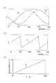
2つの部材が相対回転すると、第1、第2磁気センサ3、4は、sinカーブ(正弦曲線)とcosカーブ(余弦曲線)を出力し{図3(a)参照}、角度演算装置(マイクロコンピュータ)によって、2つの出力を逆三角関数演算で180°間隔の右上がりの直線特性に変換し{図3(b)参照}、各右上がりの直線特性を繋ぎ合わせることで、0°〜360°の回転角度出力{図3(c)参照}を得るものである(例えば、特許文献1参照)。 When the two members rotate relative to each other, the first and second
従来の回転角度検出装置は、第1、第2磁気センサ3、4が磁石2の円周付近に配置されるものであった。
磁石2の円周付近は開磁場であり、磁石2の円周付近の磁束線は一定方向に均一化されておらず、磁石2の外周端部から放射状に延びている。このため、磁石2に対する第1、第2磁気センサ3、4の微妙な位置ズレによりセンサ出力が変化し、結果的に回転検出誤差が大きくなってしまう。In the conventional rotation angle detection device, the first and second
The vicinity of the circumference of the
上記の具体的な不具合を、図9を参照して説明する。なお、回転軸に垂直な半径方向をX軸と称し、回転軸に垂直でX軸に対して回転方向に90°異なった半径方向をY軸と称し、回転軸をZ軸と称する。
(第1磁気センサ3の位置ズレによる出力変動)
第1磁気センサ3の位置ズレによる出力変動を図9(a)を参照して説明する。
まず、第1磁気センサ3の取付位置が規定の位置に取り付けられた場合の出力波形を実線A1に示す。
第1磁気センサ3の取付位置がY軸方向に1mmズレた場合は、出力波形が一点鎖線A2に示すように、実線A1に比較して大きくズレてしまう。
また、第1磁気センサ3の取付位置がZ軸方向に1mmズレた場合も、出力波形が破線A3に示すように、実線A1に比較して多少ズレてしまう。The specific malfunction will be described with reference to FIG. The radial direction perpendicular to the rotation axis is referred to as the X axis, the radial direction perpendicular to the rotation axis and different from the X axis by 90 ° in the rotation direction is referred to as the Y axis, and the rotation axis is referred to as the Z axis.
(Output fluctuation due to displacement of the first magnetic sensor 3)
The output fluctuation due to the displacement of the first
First, an output waveform when the mounting position of the first
When the mounting position of the first
Further, when the mounting position of the first
(第2磁気センサ4の位置ズレによる出力変動)
第2磁気センサ4の位置ズレによる出力変動を図9(b)を参照して説明する。
まず、第2磁気センサ4の取付位置が規定の位置に取り付けられた場合の出力波形を実線B1に示す。
第2磁気センサ4の取付位置がY軸方向に1mmズレた場合は、出力波形が一点鎖線B2に示すように、実線B1に比較して大きくズレてしまう。
また、第2磁気センサ4の取付位置がZ軸方向に1mmズレた場合も、出力波形が破線B3に示すように、実線B1に比較して多少ズレてしまう。(Output fluctuation due to misalignment of the second magnetic sensor 4)
The output fluctuation due to the positional deviation of the second
First, an output waveform when the mounting position of the second
When the mounting position of the second
Even when the mounting position of the second
(演算角度誤差) 第1、第2磁気センサ3、4の位置ズレによる回転検出誤差を図9(c)を参照して説明する。
上述したように、第1磁気センサ3または第2磁気センサ4の取付位置がY軸方向に1mmズレた場合、第1、第2磁気センサ3、4の出力から角度演算を行うと、実線C1に示すように、回転検出誤差が大きくなってしまう。
また、第1磁気センサ3または第2磁気センサ4の取付位置がZ軸方向に1mmズレた場合も、第1、第2磁気センサ3、4の出力から角度演算を行うと、破線C2に示すように、回転検出誤差が生じてしまう。
As described above, when the mounting position of the first
In addition, even when the mounting position of the first
本発明は、上記問題点に鑑みてなされたものであり、その目的は、磁石と、第1、第2磁気センサとに相対的な位置ズレが生じても、回転検出誤差が生じない回転角度検出装置の提供にある。 The present invention has been made in view of the above problems, and its object is to provide a rotation angle at which no rotation detection error occurs even if a relative positional shift occurs between the magnet and the first and second magnetic sensors. To provide a detection device.
[請求項1の手段]
本願発明者らは、磁束の向きが同方向で同一性能の2つの磁石を回転軸方向に空隙を隔てて配置し、2つの磁石の中心側に磁性体製のシャフトを配置した状態では、2つの磁石の回転軸方向の間で、且つシャフトの外周端と磁石の外周端の間の空間に、磁束線が半径方向に揃って向く閉磁場が形成されることを見出した。
そこで、請求項1の手段を採用する回転角度検出装置は、閉磁場が形成される空間(2つの磁石の回転軸方向の間で、且つシャフトの外周端と磁石の外周端の間の空間)に、第1、第2磁気センサを配置したものである。
第1、第2磁気センサが配置される空間は閉磁場であり、その空間は磁束線が半径方向に揃って向くものであるため、磁石(2つの磁石)と、第1、第2磁気センサとに相対的な位置ズレが生じても、第1、第2磁気センサに与えられる磁束線の向きの変化が抑えられ、回転検出誤差が抑えられる。[Means of claim 1]
In the state in which two magnets having the same magnetic flux direction and the same performance are arranged with a gap in the direction of the rotation axis and a magnetic shaft is arranged on the center side of the two magnets, the inventors have It has been found that a closed magnetic field in which magnetic flux lines are aligned in the radial direction is formed between the rotation axis directions of two magnets and in a space between the outer peripheral end of the shaft and the outer peripheral end of the magnet.
Therefore, the rotation angle detection device employing the means of
Since the space in which the first and second magnetic sensors are arranged is a closed magnetic field, and the magnetic flux lines are aligned in the radial direction in the space, the magnet (two magnets) and the first and second magnetic sensors Even if a relative misalignment occurs, a change in the direction of the magnetic flux lines applied to the first and second magnetic sensors is suppressed, and a rotation detection error is suppressed.
[請求項2の手段]
2つの磁石の回転軸方向の間の中央部付近で、且つシャフトの外周端と磁石の外周端の間の中央部付近は、磁束ベクトルが均一になっている。
そこで、請求項2の手段を採用し、第1、第2磁気センサを磁束ベクトルが均一な空間(2つの磁石の回転軸方向の間の略中央部で、且つシャフトの外周端と磁石の外周端の間の略中央部)に配置する。
このように、第1、第2磁気センサが、磁束ベクトルの均一な空間に配置されるため、磁石(2つの磁石)と、第1、第2磁気センサとに相対的な位置ズレが生じても、回転検出誤差が生じない。[Means of claim 2]
The magnetic flux vector is uniform in the vicinity of the central portion between the two magnets in the rotation axis direction and in the vicinity of the central portion between the outer peripheral end of the shaft and the outer peripheral end of the magnet.
Therefore, the means of
As described above, since the first and second magnetic sensors are arranged in a space where the magnetic flux vector is uniform, a relative positional deviation occurs between the magnets (two magnets) and the first and second magnetic sensors. However, no rotation detection error occurs.
[請求項3の手段]
請求項3の手段を採用する回転角度検出装置は、第1磁気センサと第2磁気センサが回転方向に90°異なった位置に配置されるものである。
このように、第1磁気センサと第2磁気センサが異なった位置に配置された状態で、第1、第2磁気センサの一方、または両方が位置ズレしても、第1、第2磁気センサに与えられる磁束線の向きの変化が抑えられる。[Means of claim 3]
In the rotation angle detection device employing the means of
Thus, even if one or both of the first and second magnetic sensors are misaligned in a state where the first magnetic sensor and the second magnetic sensor are arranged at different positions, the first and second magnetic sensors The change in the direction of the magnetic flux lines applied to the is suppressed.
[請求項4の手段]
請求項4の手段を採用する回転角度検出装置は、第1、第2磁気センサを1つのチップ内に搭載するものである。
このように、第1、第2磁気センサを1つのチップ内に搭載することにより、組付け性が向上するとともに、第1、第2磁気センサ(1つのチップ)の搭載性の自由度が高まる。[Means of claim 4]
The rotation angle detecting device adopting the means of
As described above, by mounting the first and second magnetic sensors in one chip, the assemblability is improved and the degree of freedom in mounting the first and second magnetic sensors (one chip) is increased. .
[請求項5の手段]
シャフトが磁性体であるため、シャフトの影響によって第1、第2磁気センサの出力波形の波高が揃わない場合が想定される。
このような場合は、請求項5の手段を採用し、第1、第2磁気センサが配置されたチップの配置角度を傾斜させて、第1、第2磁気センサの出力波形の波高を揃える。[Means of claim 5]
Since the shaft is a magnetic body, it is assumed that the wave heights of the output waveforms of the first and second magnetic sensors are not uniform due to the influence of the shaft.
In such a case, the means of
[請求項6の手段]
シャフトが磁性体であるため、シャフトの影響によって第1、第2磁気センサの出力波形の波高が揃わない場合が想定される。
このような場合は、請求項6の手段を採用し、第1、第2磁気センサの出力波形の波高を、電気回路または角度演算装置における演算により揃える。[Means of claim 6]
Since the shaft is a magnetic body, it is assumed that the wave heights of the output waveforms of the first and second magnetic sensors are not uniform due to the influence of the shaft.
In such a case, the means of
[請求項7の手段]
請求項7の手段を採用する回転角度検出装置の2つの磁石は、回転軸に垂直な半径方向に磁束が向くように着磁され、磁束の発生部と磁束の吸引部の着磁方向が180°逆方向の永久磁石である。
これによって、第1、第2磁気センサから360°周期のsinカーブとcosカーブの出力を取り出すことができ、2つの出力を逆三角関数演算で180°間隔の右上がりの直線特性に変換し、各右上がりの直線特性を繋ぎ合わせることで、0°〜360°の回転角度出力を得ることができる。[Means of Claim 7]
The two magnets of the rotation angle detecting device adopting the means of
As a result, the output of the sin curve and the cosine curve with a period of 360 ° can be taken out from the first and second magnetic sensors, and the two outputs are converted into a straight line characteristic with an upward slope of 180 ° by inverse trigonometric function calculation. A rotation angle output of 0 ° to 360 ° can be obtained by connecting the linear characteristics that rise to the right.
最良の形態の回転角度検出装置は、相対回転する一方に設けられ、リング状もしくは円板状を呈し、その外周円の軸心と回転軸とが略一致し、回転軸に垂直な半径方向に磁束の発生部と磁束の吸引部が向く磁石と、相対回転する他方に設けられ、磁石の発生する磁気の変化を検出する第1磁気センサと、相対回転する他方に設けられ、磁石の発生する磁気の変化を第1磁気センサに対して90°位相をずらして検出する第2磁気センサとを具備し、相対回転する一方および他方の相対回転角度を、第1、第2磁気センサを通過する磁束によって検出する。
磁石は、同一性能で、磁束の発生部と磁束の吸引部が同方向に向くものが回転軸方向に空隙を隔てて2つ配置される。
この2つの磁石の中心側には、磁性体製のシャフトが配置される。
そして、第1、第2磁気センサは、2つの磁石の回転軸方向の間で、且つシャフトの外周端と磁石の外周端の間に配置されるものである。The rotation angle detection device of the best mode is provided on one side that rotates relative to each other, has a ring shape or a disk shape, and the axis of the outer circumference circle and the rotation axis substantially coincide with each other in the radial direction perpendicular to the rotation axis. A magnet that faces the magnetic flux generation part and the magnetic flux attraction part, and a first magnetic sensor that is provided on the other side that rotates relative to each other and that detects a change in magnetism generated by the magnet, and that is provided on the other side that rotates relative to the magnet. A second magnetic sensor that detects a change in magnetism with a phase difference of 90 ° with respect to the first magnetic sensor, and passes through the first and second magnetic sensors at one and the other relative rotational angles. Detect by magnetic flux.
Two magnets having the same performance and having a magnetic flux generating portion and a magnetic flux attracting portion facing in the same direction are arranged with a gap in the rotation axis direction.
A magnetic shaft is arranged on the center side of the two magnets.
The first and second magnetic sensors are arranged between the rotation axis directions of the two magnets and between the outer peripheral end of the shaft and the outer peripheral end of the magnet.
実施例1を図1〜図5を参照して説明する。
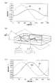
まず、図1、図2を参照して回転角度検出装置の基本構成を説明する。なお、図1(a)は回転角度検出装置の概略斜視図、図1(b)は回転角度検出装置の概略側面図、図1(c)は図1(b)のA−A線に沿う断面の斜視図である。また、図2は回転角度検出装置における電気回路の概略図である。
以下では、回転軸に垂直な半径方向をX軸と称し、回転軸に垂直でX軸に対して回転方向に90°異なった半径方向をY軸と称し、回転軸をZ軸と称する。A first embodiment will be described with reference to FIGS.
First, the basic configuration of the rotation angle detection device will be described with reference to FIGS. 1 and 2. 1A is a schematic perspective view of the rotation angle detection device, FIG. 1B is a schematic side view of the rotation angle detection device, and FIG. 1C is along the line AA in FIG. 1B. It is a perspective view of a cross section. FIG. 2 is a schematic diagram of an electric circuit in the rotation angle detection device.
Hereinafter, the radial direction perpendicular to the rotation axis is referred to as the X axis, the radial direction perpendicular to the rotation axis and different from the X axis by 90 ° in the rotation direction is referred to as the Y axis, and the rotation axis is referred to as the Z axis.
この実施例1に示す回転角度検出装置は、シャフト1(相対回転する一方の部材:この実施例では回転部材)、シャフト1に固定された2つの磁石2、図示しない固定部材(相対回転する他方の部材:例えば、ハウジングに固定された回路基板等)に搭載された第1、第2磁気センサ3、4、および角度演算装置5を備える。 The rotation angle detection device shown in the first embodiment includes a shaft 1 (one member that rotates relatively: a rotating member in this embodiment), two
シャフト1は、磁性体製(例えば、鉄等の磁性体金属)で円柱棒状を呈するものであり、例えばスロットル開度センサにおいては、スロットルバルブ(角度検出の対象物)と一体に回転するものである。 The
2つの磁石2は、シャフト1に固定されて、シャフト1と一体に回転する。
2つの磁石2は、一定の厚みを有し、リング状もしくは円板状を呈する永久磁石であり、その外周円の軸心とZ軸とが一致し、Z軸に垂直な半径方向に磁束の発生部(S極)と磁束の吸引部(N極)が向くものである。
2つの磁石2は、径寸法、厚み寸法、着磁力など性能が同じで、磁束の発生部と磁束の吸引部が同方向に向き、Z軸方向に所定の空隙を隔ててシャフト1に固定されている。
この実施例1の2つの磁石2は、磁束の発生部と磁束の吸引部の着磁方向が180°逆方向に向くよう半径方向に着磁されている。The two
The two
The two
The two
第1磁気センサ3は、固定部材(例えば、ハウジングに固定された回路基板等)に固定され、磁気検出面を通過する磁束の流れ方向および磁束密度に応じた出力を発生する第1ホール素子3a(図2参照)を内蔵している。ここで、第1ホール素子3aは、微弱なセンサ出力を発生するものであるため、その微弱出力を増幅する第1増幅アンプ6が接続される。この第1増幅アンプ6は、第1磁気センサ3内に封入したものであっても良いし、第1磁気センサ3とは別の基板上に配置しても良い。 The first
第2磁気センサ4は、第1磁気センサ3と同様、固定部材(例えば、ハウジングに固定された回路基板等)に固定され、磁気検出面を通過する磁束の流れ方向および磁束密度に応じた出力を発生する第2ホール素子4a(図2参照)を内蔵している。ここで、第2ホール素子4aは、微弱なセンサ出力を発生するものであるため、その微弱出力を増幅する第2増幅アンプ7が接続される。この第2増幅アンプ7は、第2磁気センサ4内に封入したものであっても良いし、第2磁気センサ4とは別の基板上に配置しても良い。 Similarly to the first
第1、第2磁気センサ3、4は、それぞれの磁気検出面がZ軸に向けて配置されるとともに、第2磁気センサ3が第1磁気センサ4に対して回転方向に90°異なった位置に配置されるものである。
これによって、第1磁気センサ3に与えられる磁束線に対して、第2磁気センサ4に与えられる磁束線の位相が90°ズレることになる。この結果、第1磁気センサ3のセンサ出力に対して、第2磁気センサ4のセンサ出力の位相が90°ずれることになり、図3(a)に示すように、磁石2の回転に対して第1磁気センサ3がsinカーブのセンサ出力(図中A)を発生し、第2磁気センサ4がcosカーブのセンサ出力(図中B)を発生する。The first and second
As a result, the phase of the magnetic flux lines applied to the second
角度演算装置5は、周知構成のマイクロコンピュータであり、図2に示すように、第1磁気センサ3のセンサ出力を第1ADC8でデジタル変換して入力するとともに、第2磁気センサ4の出力を第2ADC9でデジタル変換して入力する。
角度演算装置5は、第1、第2磁気センサ3、4の出力から角度演算をするものであり、図3(a)に示すように、第1磁気センサ3のsinカーブ出力と、第2磁気センサ4のcosカーブ出力とを、図3(b)に示すように、逆三角関数演算で180°間隔の右上がりの直線特性Cに変換{tanθ=sinθ/cosθ→θ=tan-1(sinθ/cosθ)}する。そして、角度演算装置5は、図3(c)に示すように、各右上がりの直線特性Cを繋ぎ合わせ、磁石2の回転0°〜360°に対応した回転角度出力D(アナログ信号)を発生するものである。The
The
(第1、第2磁気センサ3、4の取付位置の説明)
上述したように、円板形状を呈した2つの磁石2は、磁束の向きが同一方向で、且つ同一性能(形状等を含む)であり、所定の空隙を隔てて磁性体製のシャフト1に固定されたものである。
このような構成を採用することにより、図4に示されるように、2つの磁石2のZ軸方向の間で、且つシャフト1の外周端と磁石2の外周端の間の空間には、磁束線が半径方向に揃って向く閉磁場(図中、一点鎖線Iで囲む範囲)が形成される。
そこで、この実施例1の回転角度検出装置は、閉磁場が形成される空間(2つの磁石2のZ軸方向の間で、且つシャフト1の外周端と磁石2の外周端の間の空間)に、第1、第2磁気センサ3、4を配置する構成を採用している。(Description of mounting positions of the first and second
As described above, the two
By adopting such a configuration, as shown in FIG. 4, a magnetic flux is formed in the space between the outer peripheral end of the
Therefore, the rotation angle detection device according to the first embodiment has a space in which a closed magnetic field is formed (a space between the Z-axis direction of the two
特に、図4中、破線IIで囲む範囲に示すように、2つの磁石2のZ軸方向の間の中央部付近で、且つシャフト1の外周端と磁石2の外周端の間の中央部付近は、磁束ベクトルが均一になっている。
このため、第1、第2磁気センサ3、4を破線IIで囲む範囲内(2つの磁石2のZ軸方向の間の中央部付近で、且つシャフト1の外周端と磁石2の外周端の間の中央部付近)に配置することが望ましい。In particular, as shown in a range surrounded by a broken line II in FIG. 4, in the vicinity of the center between the two
For this reason, the first and second
(実施例1の効果)
回転角度検出装置は、上述したように、閉磁場が形成される空間(図4中、一点鎖線Iで囲む範囲)、特に磁束ベクトルが均一の空間(図4中、破線IIで囲む範囲)に、磁気検出面を有する第1、第2磁気センサ3、4を配置する構成を採用している。
このため、第1、第2磁気センサ3、4の一方または両方の取付位置が多少ズレても、第1、第2磁気センサ3、4に与えられる磁束線の向きの変化が抑えられる。これにより、第1、第2磁気センサ3、4の位置ズレが生じても回転検出誤差が生じる不具合を無くすことができる。(Effect of Example 1)
As described above, the rotation angle detection device is in a space where a closed magnetic field is formed (in a range surrounded by an alternate long and short dash line I in FIG. 4), particularly in a space where a magnetic flux vector is uniform (a range surrounded by a broken line II in FIG. 4). The first and second
For this reason, even if the mounting position of one or both of the first and second
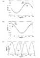
上記の具体的な効果を、図5を参照して説明する。
(第1磁気センサ3の位置ズレによる出力変動)
第1磁気センサ3の位置ズレによる出力変動を図5(a)を参照して説明する。
まず、第1磁気センサ3の取付位置が規定の位置に取り付けられた場合の出力波形を実線A1に示す。
第1磁気センサ3の取付位置がY軸方向に1mmズレた場合の出力波形を実線A2に示す。このように、第1磁気センサ3の取付位置がY軸方向に1mmズレても、規定の位置に取り付けられた場合の実線A1とほぼ一致した出力波形が得られる。
また、第1磁気センサ3の取付位置がZ軸方向に1mmズレた場合の出力波形を実線A3に示す。このように、第1磁気センサ3の取付位置がZ軸方向に1mmズレても、規定の位置に取り付けられた場合の実線A1と一致した出力波形が得られる。The specific effect will be described with reference to FIG.
(Output fluctuation due to displacement of the first magnetic sensor 3)
The output fluctuation due to the displacement of the first
First, an output waveform when the mounting position of the first
An output waveform when the mounting position of the first
An output waveform when the mounting position of the first
(第2磁気センサ4の位置ズレによる出力変動)
第2磁気センサ4の位置ズレによる出力変動を図5(b)を参照して説明する。
まず、第2磁気センサ4の取付位置が規定の位置に取り付けられた場合の出力波形を実線B1に示す。
第2磁気センサ4の取付位置がY軸方向に1mmズレた場合の出力波形を実線B2に示す。このように、第2磁気センサ4の取付位置がY軸方向に1mmズレても、規定の位置に取り付けられた場合の実線B1とほぼ一致した出力波形が得られる。
また、第2磁気センサ4の取付位置がZ軸方向に1mmズレた場合の出力波形を実線B3に示す。このように、第2磁気センサ4の取付位置がZ軸方向に1mmズレても、規定の位置に取り付けられた場合の実線B1と一致した出力波形が得られる。(Output fluctuation due to misalignment of the second magnetic sensor 4)
The output fluctuation due to the positional deviation of the second
First, an output waveform when the mounting position of the second
A solid line B2 shows an output waveform when the mounting position of the second
An output waveform when the mounting position of the second
(演算角度誤差) 第1、第2磁気センサ3、4の位置ズレによる回転検出誤差を図5(c)を参照して説明する。
上述したように、第1磁気センサ3または第2磁気センサ4の取付位置がY軸方向に1mmズレても、規定の位置に取り付けられた場合とほぼ一致した出力波形が得られるため、第1磁気センサ3または第2磁気センサ4の取付位置がY軸方向に1mmズレた状態のセンサ出力から角度演算を行っても、実線C1に示すように、回転検出誤差が殆ど生じない。
また、第1磁気センサ3または第2磁気センサ4の取付位置がZ軸方向に1mmズレても、規定の位置に取り付けられた場合と一致した出力波形が得られるため、第1磁気センサ3または第2磁気センサ4の取付位置がZ軸方向に1mmズレた状態のセンサ出力から角度演算を行っても、実線C2に示すように、回転検出誤差が生じない。(Calculation Angle Error) The rotation detection error due to the positional deviation of the first and second
As described above, even if the mounting position of the first
In addition, even if the mounting position of the first
この図5に示す実験結果からも、閉磁場が形成される空間(図4中、一点鎖線Iで囲む範囲)、特に磁束ベクトルが均一な空間(図4中、破線IIで囲む範囲)に、第1、第2磁気センサ3、4を配置する構成を採用することにより、第1、第2磁気センサ3、4の一方または両方の取付位置が多少ズレたとしても回転検出誤差が抑えられることがわかる。 From the experimental results shown in FIG. 5 as well, in a space where a closed magnetic field is formed (in a range surrounded by an alternate long and short dash line I in FIG. 4), particularly in a space where a magnetic flux vector is uniform (a range surrounded by a broken line II in FIG. 4) By adopting a configuration in which the first and second
実施例2を図6、図7を参照して説明する。なお、実施例1と同一符号は、同一機能物を示すものである。
上記の実施例1では、第1磁気センサ3と第2磁気センサ4を回転方向に90°離れた位置に配置する例を示した。
これに対し、この実施例2では、第1、第2磁気センサ3、4を1つのチップ10内において隣接配置するものであり、第1磁気センサ3の磁気検出面に対し、第2磁気センサ4の磁気検出面を略直角方向に向けて配置して、第1磁気センサ3の検出する磁気変化に対し、第2磁気センサ4の検出する磁気変化の位相が90°ずれるように設けられている。A second embodiment will be described with reference to FIGS. In addition, the same code | symbol as Example 1 shows the same functional thing.
In the first embodiment, the example in which the first
On the other hand, in the second embodiment, the first and second
具体的に、この実施例2では、第1磁気センサ3の磁気検出面が、図6(c)に示すように、Z軸に向けて配置されるものであり、第2磁気センサ4の磁気検出面が、Z軸に対して垂直方向に向けて配置されるものである。これによって、第1磁気センサ3の磁気検出面に対して、略直角方向に第2磁気センサ4の磁気検出面が配置される。
このように設けられることで、第1磁気センサ3のセンサ出力に対して、第2磁気センサ4のセンサ出力の位相が90°ずれることになり、磁石2の回転に対して第1磁気センサ3が360°周期のsinカーブのセンサ出力を発生し、第2磁気センサ4が360°周期のcosカーブのセンサ出力を発生する。Specifically, in Example 2, the magnetic detection surface of the first
By providing in this way, the phase of the sensor output of the second
第1、第2磁気センサ3、4の感度比(出力波形の波高差)は、検出角度の誤差になるため、感度比は小さいほど好ましい。シャフト1は、磁性体製であるため、シャフト1の影響等によって、第1、第2磁気センサ3、4の出力波形に波高差が生じる可能性がある。
その場合は、第1、第2磁気センサ3、4を内蔵するチップ10の配置角度を傾斜させて、第1、第2磁気センサ3、4の出力波形の波高を揃える。これは、第1、第2磁気センサ3、4が検出する磁束線が半径方向に揃って向く閉磁場で形成され、軸に平行な磁束成分がないためにチップ10を所定の角度に傾斜し、2つの波高値を揃えることができるためである。The sensitivity ratio of the first and second
In this case, the arrangement angle of the
具体的な例を図7を参照して説明する。
図7(a)に示すように、シャフト1の影響等によって、第1磁気センサ3のセンサ出力(図中A1)の波高が、第2磁気センサ4のセンサ出力(図中B1)の波高より低くなる場合は、図7(b)に示すように、第1磁気センサ3の磁気検出面の向く方向を変更させずに、第2磁気センサ4の磁気検出面の向く方向が傾斜するように、チップ10の取付角度(傾斜角)αを変更する。ここで、傾斜により感度を下げる第2磁気センサ4は、cosカーブのセンサ出力を発生するものであるため、第1磁気センサ3のセンサ出力をV1、第2磁気センサ4のセンサ出力をV2とした場合、傾斜角αはα=cos-1(V1 /V2)で求めることができる。
このように、チップ10の取付角度(傾斜角)αを変更することにより、第2磁気センサ4のセンサ出力(図中B1’)の波高が低下し、図7(c)に示すように、第1磁気センサ3のセンサ出力(図中A1)の波高と、第2磁気センサ4のセンサ出力(図中B1’)の波高を同じ高さに揃えることができる。A specific example will be described with reference to FIG.
As shown in FIG. 7A, the wave height of the sensor output (A1 in the figure) of the first
Thus, by changing the mounting angle (tilt angle) α of the
なお、この実施例2では、チップ10の取付角度(傾斜角)αを変更することで、第1、第2磁気センサ3、4の出力波形の波高を揃える例を示すが、第1、第2磁気センサ3、4の出力波形の波高を、電気回路(例えば、第1増幅アンプ6または第2増幅アンプ7のゲイン)、あるいは角度演算装置5における演算(波高を揃える補正演算)により揃えても良い。また、第1、第2磁気センサ3、4の出力波形の波高を、電気回路や角度演算装置5における演算で揃える技術を、実施例1に適用しても良い。 In the second embodiment, an example in which the wave heights of the output waveforms of the first and second
(実施例2の効果)
実施例2の回転角度検出装置は、上述した実施例1の効果に加えて、次の効果を奏する。
第1、第2磁気センサ3、4を1つのチップ10内に配置しているため、第1、第2磁気センサ3、4の搭載スペースが1箇所で済む。これによって、第1、第2磁気センサ3、4の搭載性の自由度が高まる。
また、1つのチップ10内に第1、第2磁気センサ3、4を隣接配置しているため、部品点数が減るとともに、組付け性が向上する。
さらに、第1、第2磁気センサ3、4を隣接配置しているので、第1、第2磁気センサ3、4の環境条件が略同等であり、温度変化による出力ズレも略同等となるため、良好で且つ安定した角度精度が得られる。(Effect of Example 2)
In addition to the effect of Example 1 mentioned above, the rotation angle detection apparatus of Example 2 has the following effect.
Since the first and second
Further, since the first and second
Furthermore, since the first and second
〔変形例〕
上記の実施例では、第1、第2磁気センサ3、4を固定し、磁石2を回転させた例を示したが、逆に磁石2を固定し、第1、第2磁気センサ3、4を回転させる構造を採用しても良い。また、磁石2と第1、第2磁気センサ3、4の双方が共に回転する構造を採用しても良い。
上記の実施例では、第1、第2磁気センサの一例としてホール素子を用いた例を示したが、磁気抵抗素子(MRE)など、他の磁気センサを用いても良い。[Modification]
In the above embodiment, the first and second
In the above embodiment, the Hall element is used as an example of the first and second magnetic sensors. However, other magnetic sensors such as a magnetoresistive element (MRE) may be used.
上記の実施例では、磁石2を永久磁石で構成した例を示したが、通電によって磁力を発生する電磁石を用いても良い。
上記の実施例では、回転角度検出装置の具体的な一例としてスロットルバルブの開度を検出する例を示したが、エンジンのクランクシャフトの回転角度、産業ロボットのアーム部の回転角度等、他の回転角度を検出するように設けても良い。In the above embodiment, an example in which the
In the above embodiment, an example of detecting the opening degree of the throttle valve is shown as a specific example of the rotation angle detection device. However, the rotation angle of the crankshaft of the engine, the rotation angle of the arm portion of the industrial robot, etc. You may provide so that a rotation angle may be detected.
1 シャフト
2 磁石
3 第1磁気センサ
4 第2磁気センサ
5 角度演算装置
10 1つのチップ
DESCRIPTION OF
Claims (7)
Translated fromJapanese相対回転する他方に設けられ、前記磁石の発生する磁気の変化を検出する第1磁気センサと、
相対回転する他方に設けられ、前記磁石の発生する磁気の変化を前記第1磁気センサに対して90°位相をずらして検出する第2磁気センサとを具備し、
前記相対回転する一方および他方の相対回転角度を、前記第1、第2磁気センサを通過する磁束によって検出する回転角度検出装置において、
前記磁石は、同一性能で、前記磁束の発生部と前記磁束の吸引部が同方向に向くものが回転軸方向に空隙を隔てて2つ配置されるものであり、
この2つの磁石の中心側には、磁性体製のシャフトが配置されるものであり、
前記第1、第2磁気センサは、前記2つの磁石の回転軸方向の間で、且つ前記シャフトの外周端と前記磁石の外周端の間に配置されることを特徴とする回転角度検出装置。It is provided on one side that rotates relative to each other, has a ring shape or a disk shape, the axis of the outer circumference circle and the rotation axis substantially coincide with each other, and a magnetic flux generation part and a magnetic flux suction part are provided in the radial direction perpendicular to the rotation axis. A facing magnet,
A first magnetic sensor provided on the other side of the relative rotation for detecting a change in magnetism generated by the magnet;
A second magnetic sensor that is provided on the other side of the relative rotation and detects a change in magnetism generated by the magnet with a 90 ° phase shift with respect to the first magnetic sensor;
In the rotation angle detection device for detecting the relative rotation angle of the one and the other rotating relative to each other by a magnetic flux passing through the first and second magnetic sensors,
Two magnets having the same performance and the magnetic flux generation part and the magnetic flux attraction part facing in the same direction are arranged with a gap in the rotation axis direction,
On the center side of these two magnets, a magnetic shaft is arranged.
The rotation angle detecting device, wherein the first and second magnetic sensors are arranged between rotation directions of the two magnets and between an outer peripheral end of the shaft and an outer peripheral end of the magnet.
前記第1、第2磁気センサは、前記2つの磁石の回転軸方向の間の略中央部で、且つ前記シャフトの外周端と前記磁石の外周端の間の略中央部に配置されることを特徴とする回転角度検出装置。The rotation angle detection device according to claim 1,
The first and second magnetic sensors are arranged at a substantially central portion between the rotation axis directions of the two magnets and at a substantially central portion between the outer peripheral end of the shaft and the outer peripheral end of the magnet. A rotation angle detecting device.
前記第1、第2磁気センサは、それぞれの磁気検出面が回転軸に向けて配置されるとともに、前記第2磁気センサは、前記第1磁気センサに対して回転方向に90°異なった位置に配置されることを特徴とする回転角度検出装置。In the rotation angle detection device according to claim 1 or 2,
The first and second magnetic sensors have their respective magnetic detection surfaces arranged toward the rotation axis, and the second magnetic sensor is located at a position different from the first magnetic sensor by 90 ° in the rotation direction. A rotation angle detection device, characterized in that it is arranged.
前記第1、第2磁気センサは、1つのチップ内において隣接配置されるものであり、前記第2磁気センサの磁気検出面が前記第1磁気センサの磁気検出面に対して略直角方向に向いて配置されることを特徴とする回転角度検出装置。In the rotation angle detection device according to claim 1 or 2,
The first and second magnetic sensors are arranged adjacent to each other in one chip, and the magnetic detection surface of the second magnetic sensor is oriented substantially perpendicular to the magnetic detection surface of the first magnetic sensor. And a rotation angle detecting device.
前記第1、第2磁気センサが配置されたチップの配置角度を傾斜させて、前記第1、第2磁気センサの出力波形の波高を揃えることを特徴とする回転角度検出装置。In the rotation angle detection device according to claim 4,
A rotation angle detecting device characterized in that an arrangement angle of a chip on which the first and second magnetic sensors are arranged is tilted so that the output waveforms of the first and second magnetic sensors are aligned.
前記第1、第2磁気センサの出力波形の波高を、電気回路または角度演算装置における演算により揃えることを特徴とする回転角度検出装置。In the rotation angle detection device according to claim 4,
A rotation angle detection device characterized in that the wave heights of the output waveforms of the first and second magnetic sensors are made uniform by calculation in an electric circuit or an angle calculation device.
前記2つの磁石は、回転軸に垂直な半径方向に磁束が向くように着磁され、前記磁束の発生部と前記磁束の吸引部の着磁方向が180°逆方向の永久磁石であることを特徴とする回転角度検出装置。
In the rotation angle detection apparatus in any one of Claims 1-6,
The two magnets are magnetized so that the magnetic flux is directed in a radial direction perpendicular to the rotation axis, and the magnetizing direction of the magnetic flux generating portion and the magnetic flux attracting portion is a permanent magnet having a reverse direction of 180 °. A rotation angle detecting device.
Priority Applications (3)
| Application Number | Priority Date | Filing Date | Title |
|---|---|---|---|
| JP2004231636AJP4376150B2 (en) | 2004-08-06 | 2004-08-06 | Rotation angle detector |
| US11/168,381US7319320B2 (en) | 2004-08-06 | 2005-06-29 | Rotation angle detecting device |
| DE102005036973.1ADE102005036973B4 (en) | 2004-08-06 | 2005-08-05 | Rotation angle measuring device |
Applications Claiming Priority (1)
| Application Number | Priority Date | Filing Date | Title |
|---|---|---|---|
| JP2004231636AJP4376150B2 (en) | 2004-08-06 | 2004-08-06 | Rotation angle detector |
Publications (2)
| Publication Number | Publication Date |
|---|---|
| JP2006047227A JP2006047227A (en) | 2006-02-16 |
| JP4376150B2true JP4376150B2 (en) | 2009-12-02 |
Family
ID=35756782
Family Applications (1)
| Application Number | Title | Priority Date | Filing Date |
|---|---|---|---|
| JP2004231636AExpired - Fee RelatedJP4376150B2 (en) | 2004-08-06 | 2004-08-06 | Rotation angle detector |
Country Status (3)
| Country | Link |
|---|---|
| US (1) | US7319320B2 (en) |
| JP (1) | JP4376150B2 (en) |
| DE (1) | DE102005036973B4 (en) |
Cited By (1)
| Publication number | Priority date | Publication date | Assignee | Title |
|---|---|---|---|---|
| TWI864477B (en)* | 2022-11-01 | 2024-12-01 | 財團法人工業技術研究院 | Battery-free rotation detecting device |
Families Citing this family (75)
| Publication number | Priority date | Publication date | Assignee | Title |
|---|---|---|---|---|
| US7469604B2 (en)* | 2005-10-21 | 2008-12-30 | Stoneridge Control Devices, Inc. | Sensor system including a magnetized shaft |
| JP4706518B2 (en)* | 2006-03-16 | 2011-06-22 | 日本精機株式会社 | Angle detector |
| JP2007271341A (en)* | 2006-03-30 | 2007-10-18 | Aisin Seiki Co Ltd | Rotation detection sensor |
| DE102006052825B4 (en)* | 2006-06-14 | 2018-09-06 | Rayonex Biomedical Gmbh | Method for determining the roll angle of a device with a housing |
| JP2008014671A (en)* | 2006-07-03 | 2008-01-24 | Yaskawa Electric Corp | Magnetic encoder device |
| US7456629B2 (en)* | 2006-07-11 | 2008-11-25 | Continental Automotive Systems Us, Inc. | Rotary angle sensing system |
| JP5021253B2 (en) | 2006-08-24 | 2012-09-05 | 株式会社デンソー | Rotation angle detector |
| US7851957B2 (en)* | 2006-11-28 | 2010-12-14 | W.A. Krapf, Inc. | Magnetic bearing assembly for rotatable support apparatus |
| GB2450342B (en)* | 2007-06-20 | 2012-05-16 | P G Drives Technology Ltd | Control System |
| JP4853496B2 (en)* | 2007-07-30 | 2012-01-11 | 株式会社デンソー | Position detection sensor |
| JP2009058240A (en)* | 2007-08-30 | 2009-03-19 | Denso Corp | Rotation detector |
| EP2068124A1 (en)* | 2007-12-04 | 2009-06-10 | Metris IPR N.V. | Articulated arm measuring machine endowed with multiple measurement disks |
| DE102009021081B4 (en)* | 2008-07-18 | 2017-07-06 | Asm Automation Sensorik Messtechnik Gmbh | Magnetic angle sensor |
| US8058866B2 (en)* | 2008-09-08 | 2011-11-15 | Infineon Technologies Ag | Off-center angle measurement system |
| US9606194B2 (en) | 2008-09-08 | 2017-03-28 | Infineon Technologies Ag | Off-center angle measurement system |
| US8405386B2 (en)* | 2009-02-17 | 2013-03-26 | Goodrich Corporation | Non-contact sensor system and method for position determination |
| US8207729B2 (en) | 2009-02-17 | 2012-06-26 | Goodrich Corporation | Non-contact sensor system and method for displacement determination |
| US8164326B2 (en)* | 2009-02-17 | 2012-04-24 | Goodrich Corporation | Non-contact sensor system and method for velocity determination |
| US8203331B2 (en)* | 2009-02-17 | 2012-06-19 | Goodrich Corporation | Non-contact sensor system and method for selection determination |
| DE102009015920B4 (en) | 2009-03-25 | 2014-11-20 | Faro Technologies, Inc. | Device for optically scanning and measuring an environment |
| US9551575B2 (en) | 2009-03-25 | 2017-01-24 | Faro Technologies, Inc. | Laser scanner having a multi-color light source and real-time color receiver |
| TWI680928B (en) | 2009-04-10 | 2020-01-01 | 美商辛波提克有限責任公司 | Vertical lift system and method for transferring uncontained case unit to and from a multilevel storage structure |
| US9321591B2 (en) | 2009-04-10 | 2016-04-26 | Symbotic, LLC | Autonomous transports for storage and retrieval systems |
| US9210288B2 (en) | 2009-11-20 | 2015-12-08 | Faro Technologies, Inc. | Three-dimensional scanner with dichroic beam splitters to capture a variety of signals |
| DE102009057101A1 (en) | 2009-11-20 | 2011-05-26 | Faro Technologies, Inc., Lake Mary | Device for optically scanning and measuring an environment |
| US9113023B2 (en) | 2009-11-20 | 2015-08-18 | Faro Technologies, Inc. | Three-dimensional scanner with spectroscopic energy detector |
| US9529083B2 (en) | 2009-11-20 | 2016-12-27 | Faro Technologies, Inc. | Three-dimensional scanner with enhanced spectroscopic energy detector |
| US8630314B2 (en) | 2010-01-11 | 2014-01-14 | Faro Technologies, Inc. | Method and apparatus for synchronizing measurements taken by multiple metrology devices |
| WO2011090895A1 (en) | 2010-01-20 | 2011-07-28 | Faro Technologies, Inc. | Portable articulated arm coordinate measuring machine with multi-bus arm technology |
| US8677643B2 (en) | 2010-01-20 | 2014-03-25 | Faro Technologies, Inc. | Coordinate measurement machines with removable accessories |
| US8942940B2 (en)* | 2010-01-20 | 2015-01-27 | Faro Technologies, Inc. | Portable articulated arm coordinate measuring machine and integrated electronic data processing system |
| US9879976B2 (en) | 2010-01-20 | 2018-01-30 | Faro Technologies, Inc. | Articulated arm coordinate measurement machine that uses a 2D camera to determine 3D coordinates of smoothly continuous edge features |
| US9163922B2 (en) | 2010-01-20 | 2015-10-20 | Faro Technologies, Inc. | Coordinate measurement machine with distance meter and camera to determine dimensions within camera images |
| US9607239B2 (en) | 2010-01-20 | 2017-03-28 | Faro Technologies, Inc. | Articulated arm coordinate measurement machine having a 2D camera and method of obtaining 3D representations |
| US8875409B2 (en) | 2010-01-20 | 2014-11-04 | Faro Technologies, Inc. | Coordinate measurement machines with removable accessories |
| US8284407B2 (en) | 2010-01-20 | 2012-10-09 | Faro Technologies, Inc. | Coordinate measuring machine having an illuminated probe end and method of operation |
| US8832954B2 (en) | 2010-01-20 | 2014-09-16 | Faro Technologies, Inc. | Coordinate measurement machines with removable accessories |
| US8898919B2 (en) | 2010-01-20 | 2014-12-02 | Faro Technologies, Inc. | Coordinate measurement machine with distance meter used to establish frame of reference |
| US8615893B2 (en) | 2010-01-20 | 2013-12-31 | Faro Technologies, Inc. | Portable articulated arm coordinate measuring machine having integrated software controls |
| US9628775B2 (en) | 2010-01-20 | 2017-04-18 | Faro Technologies, Inc. | Articulated arm coordinate measurement machine having a 2D camera and method of obtaining 3D representations |
| DE102010020925B4 (en) | 2010-05-10 | 2014-02-27 | Faro Technologies, Inc. | Method for optically scanning and measuring an environment |
| GB2501390B (en) | 2010-09-08 | 2014-08-06 | Faro Tech Inc | A laser scanner or laser tracker having a projector |
| JP5672981B2 (en)* | 2010-11-02 | 2015-02-18 | 株式会社ユニバーサルエンターテインメント | Gaming machine and reel device thereof |
| AU2011239305B2 (en) | 2010-11-02 | 2015-11-26 | Aruze Gaming America Inc. | Gaming machine and reel device thereof |
| US9168654B2 (en) | 2010-11-16 | 2015-10-27 | Faro Technologies, Inc. | Coordinate measuring machines with dual layer arm |
| US9187244B2 (en) | 2010-12-15 | 2015-11-17 | Symbotic, LLC | BOT payload alignment and sensing |
| US8696010B2 (en) | 2010-12-15 | 2014-04-15 | Symbotic, LLC | Suspension system for autonomous transports |
| US9561905B2 (en) | 2010-12-15 | 2017-02-07 | Symbotic, LLC | Autonomous transport vehicle |
| US11078017B2 (en) | 2010-12-15 | 2021-08-03 | Symbotic Llc | Automated bot with transfer arm |
| US8965619B2 (en) | 2010-12-15 | 2015-02-24 | Symbotic, LLC | Bot having high speed stability |
| US9499338B2 (en) | 2010-12-15 | 2016-11-22 | Symbotic, LLC | Automated bot transfer arm drive system |
| US20130342190A1 (en)* | 2011-08-17 | 2013-12-26 | Nicholas William Payne | Through Shaft Rotary Position Sensor |
| DE102012100609A1 (en) | 2012-01-25 | 2013-07-25 | Faro Technologies, Inc. | Device for optically scanning and measuring an environment |
| US8997362B2 (en) | 2012-07-17 | 2015-04-07 | Faro Technologies, Inc. | Portable articulated arm coordinate measuring machine with optical communications bus |
| US9513107B2 (en) | 2012-10-05 | 2016-12-06 | Faro Technologies, Inc. | Registration calculation between three-dimensional (3D) scans based on two-dimensional (2D) scan data from a 3D scanner |
| DE102012109481A1 (en) | 2012-10-05 | 2014-04-10 | Faro Technologies, Inc. | Device for optically scanning and measuring an environment |
| US10067231B2 (en) | 2012-10-05 | 2018-09-04 | Faro Technologies, Inc. | Registration calculation of three-dimensional scanner data performed between scans based on measurements by two-dimensional scanner |
| JP2015052557A (en)* | 2013-09-09 | 2015-03-19 | 株式会社東海理化電機製作所 | Magnetic position detector |
| CN105705441B (en) | 2013-09-13 | 2018-04-10 | 西姆伯蒂克有限责任公司 | Autonomous transport car, the method for storing and fetching system and selection face being transmitted in the system |
| US9618365B2 (en)* | 2014-09-02 | 2017-04-11 | Infineon Technologies Ag | Angle sensor system having a magnetic sensor |
| WO2016111671A1 (en) | 2015-01-05 | 2016-07-14 | Compagnie Generale Des Etablissements Michelin | Multiple row sensing device for a tire |
| WO2016111672A1 (en) | 2015-01-05 | 2016-07-14 | Compagnie Generale Des Etablissements Michelin | Method of using multiple row sensing device for a tire |
| US10024690B2 (en)* | 2015-04-14 | 2018-07-17 | Texas Instruments Incorporated | Incremental rotary encoder using hall effect sensors and magnetic detents |
| WO2016175783A1 (en)* | 2015-04-29 | 2016-11-03 | Compagnie Generale Des Etablissements Michelin | Sensing device with proximity detection for tire inspection |
| WO2017090153A1 (en)* | 2015-11-26 | 2017-06-01 | 三菱電機株式会社 | Angle detection device and electric power steering device |
| DE102015122844A1 (en) | 2015-12-27 | 2017-06-29 | Faro Technologies, Inc. | 3D measuring device with battery pack |
| DE102016102828B4 (en)* | 2016-02-18 | 2023-04-27 | Infineon Technologies Ag | Magnetic angle sensor device and method |
| JP6278050B2 (en) | 2016-03-11 | 2018-02-14 | Tdk株式会社 | Rotation angle detection device and rotary machine device |
| JP6278051B2 (en)* | 2016-03-11 | 2018-02-14 | Tdk株式会社 | Rotation angle detector |
| DE102017128869B3 (en)* | 2017-12-05 | 2019-05-29 | Infineon Technologies Ag | Magnetic angle sensor arrangement and method for estimating a rotation angle |
| FR3079927B1 (en)* | 2018-04-06 | 2020-11-20 | Electricfil Automotive | MAGNETIC POSITION SENSOR |
| FR3082615B1 (en) | 2018-06-15 | 2020-10-16 | Electricfil Automotive | METHOD OF DETERMINING A RELATIVE ANGULAR POSITION BETWEEN TWO PIECES |
| FR3087256B1 (en) | 2018-10-15 | 2020-10-30 | Electricfil Automotive | METHOD AND SENSOR SYSTEM FOR DETERMINING A RELATIVE ANGULAR POSITION BETWEEN TWO PIECES, AND METHOD OF MANUFACTURING A MAGNETIC BODY |
| JP2020101439A (en)* | 2018-12-21 | 2020-07-02 | 株式会社竹中製作所 | Gas meter and manufacturing method thereof |
| US11175160B2 (en)* | 2019-10-18 | 2021-11-16 | Allegro Microsystems, Llc | Magnetic field sensor and method with reduced distortion measurement in sideshaft applications |
Family Cites Families (10)
| Publication number | Priority date | Publication date | Assignee | Title |
|---|---|---|---|---|
| US3162804A (en)* | 1961-09-15 | 1964-12-22 | Gen Precision Inc | Translating instrument employing hall-effect device |
| US3689836A (en)* | 1970-10-08 | 1972-09-05 | Westinghouse Electric Corp | Magnetodiode pulse initiator |
| JPS58159653A (en)* | 1982-03-17 | 1983-09-22 | Pioneer Electronic Corp | Brushless motor |
| JPS6068624A (en)* | 1983-09-26 | 1985-04-19 | Toshiba Corp | Self-inspection system of lsi |
| US5184040A (en) | 1989-09-04 | 1993-02-02 | Lim Jong H | Electric power generators having like numbers of magnets and coils |
| IL96129A0 (en)* | 1990-07-20 | 1991-07-18 | Spectronix Ltd | Method and apparatus for detecting a fire,explosion,or projectile-penetration in a monitored space |
| US5602472A (en)* | 1993-01-15 | 1997-02-11 | Hughes Electronics | Apparatus and method for determining angular position and rotational speed using a rotating magnet and a directional magnetometer |
| JP2003075108A (en) | 2001-09-04 | 2003-03-12 | Asahi Kasei Corp | Rotation angle sensor |
| DE10334869B3 (en)* | 2003-07-29 | 2004-09-16 | Tech3 E.K. | Rotation angle sensor has a rotating shaft with attached permanent magnets, with angular measurements based on both axial displacement of the shaft and sinusoidal and cosinusoidal signals generated by it |
| JP4470577B2 (en)* | 2004-05-14 | 2010-06-02 | 株式会社デンソー | Rotation angle detector |
- 2004
- 2004-08-06JPJP2004231636Apatent/JP4376150B2/ennot_activeExpired - Fee Related
- 2005
- 2005-06-29USUS11/168,381patent/US7319320B2/ennot_activeExpired - Fee Related
- 2005-08-05DEDE102005036973.1Apatent/DE102005036973B4/ennot_activeExpired - Fee Related
Cited By (1)
| Publication number | Priority date | Publication date | Assignee | Title |
|---|---|---|---|---|
| TWI864477B (en)* | 2022-11-01 | 2024-12-01 | 財團法人工業技術研究院 | Battery-free rotation detecting device |
Also Published As
| Publication number | Publication date |
|---|---|
| US7319320B2 (en) | 2008-01-15 |
| DE102005036973B4 (en) | 2018-12-06 |
| US20060028203A1 (en) | 2006-02-09 |
| DE102005036973A1 (en) | 2006-03-09 |
| JP2006047227A (en) | 2006-02-16 |
Similar Documents
| Publication | Publication Date | Title |
|---|---|---|
| JP4376150B2 (en) | Rotation angle detector | |
| JP4470577B2 (en) | Rotation angle detector | |
| US7221153B2 (en) | Rotation angle detector | |
| US7002339B2 (en) | Rotation angle detecting device | |
| JP5128120B2 (en) | Rotation sensor | |
| JP4704065B2 (en) | Bearing with rotation detector | |
| JP2007263585A (en) | Rotation angle detector | |
| JP5041401B2 (en) | Rotation sensor | |
| US20060170419A1 (en) | Rotation angle detector | |
| JP5131537B2 (en) | Angle detector | |
| US7710110B2 (en) | Rotary sensor with rotary sensing element and rotatable hollow magnet | |
| JPWO2008050581A1 (en) | Rotation angle detector | |
| JP2004251831A (en) | Rotary angle detector | |
| US6271663B1 (en) | Rotation detector operable to measure magnetism direction change | |
| JP2004361119A (en) | Rotational angle detector | |
| JP6477518B2 (en) | Position detection device | |
| JP4233920B2 (en) | Rotation angle detector | |
| JP2007263190A (en) | Bearing with rotation detecting device | |
| JP2005195471A (en) | Rotation angle detecting device | |
| JP4373157B2 (en) | Angle detector | |
| JP2022098153A (en) | Rotational angle sensor | |
| JP2009204510A (en) | Rotation angle detection device | |
| JP2007139644A (en) | Magnetic rotational displacement sensor | |
| JP2010210288A (en) | Encoder | |
| JP2003232379A (en) | Sliding bearing and rotation detector using it |
Legal Events
| Date | Code | Title | Description |
|---|---|---|---|
| A621 | Written request for application examination | Free format text:JAPANESE INTERMEDIATE CODE: A621 Effective date:20061023 | |
| TRDD | Decision of grant or rejection written | ||
| A01 | Written decision to grant a patent or to grant a registration (utility model) | Free format text:JAPANESE INTERMEDIATE CODE: A01 Effective date:20090908 | |
| A01 | Written decision to grant a patent or to grant a registration (utility model) | Free format text:JAPANESE INTERMEDIATE CODE: A01 | |
| A61 | First payment of annual fees (during grant procedure) | Free format text:JAPANESE INTERMEDIATE CODE: A61 Effective date:20090908 | |
| R150 | Certificate of patent or registration of utility model | Free format text:JAPANESE INTERMEDIATE CODE: R150 | |
| FPAY | Renewal fee payment (event date is renewal date of database) | Free format text:PAYMENT UNTIL: 20120918 Year of fee payment:3 | |
| FPAY | Renewal fee payment (event date is renewal date of database) | Free format text:PAYMENT UNTIL: 20120918 Year of fee payment:3 | |
| FPAY | Renewal fee payment (event date is renewal date of database) | Free format text:PAYMENT UNTIL: 20130918 Year of fee payment:4 | |
| R250 | Receipt of annual fees | Free format text:JAPANESE INTERMEDIATE CODE: R250 | |
| R250 | Receipt of annual fees | Free format text:JAPANESE INTERMEDIATE CODE: R250 | |
| R250 | Receipt of annual fees | Free format text:JAPANESE INTERMEDIATE CODE: R250 | |
| R250 | Receipt of annual fees | Free format text:JAPANESE INTERMEDIATE CODE: R250 | |
| LAPS | Cancellation because of no payment of annual fees |