JP4375472B2 - Vehicle charging control device - Google Patents
Vehicle charging control deviceDownload PDFInfo
- Publication number
- JP4375472B2 JP4375472B2JP2007275003AJP2007275003AJP4375472B2JP 4375472 B2JP4375472 B2JP 4375472B2JP 2007275003 AJP2007275003 AJP 2007275003AJP 2007275003 AJP2007275003 AJP 2007275003AJP 4375472 B2JP4375472 B2JP 4375472B2
- Authority
- JP
- Japan
- Prior art keywords
- vehicle
- potential
- power
- charging
- coupler
- Prior art date
- Legal status (The legal status is an assumption and is not a legal conclusion. Google has not performed a legal analysis and makes no representation as to the accuracy of the status listed.)
- Expired - Fee Related
Links
Images


Classifications
- B—PERFORMING OPERATIONS; TRANSPORTING
- B60—VEHICLES IN GENERAL
- B60L—PROPULSION OF ELECTRICALLY-PROPELLED VEHICLES; SUPPLYING ELECTRIC POWER FOR AUXILIARY EQUIPMENT OF ELECTRICALLY-PROPELLED VEHICLES; ELECTRODYNAMIC BRAKE SYSTEMS FOR VEHICLES IN GENERAL; MAGNETIC SUSPENSION OR LEVITATION FOR VEHICLES; MONITORING OPERATING VARIABLES OF ELECTRICALLY-PROPELLED VEHICLES; ELECTRIC SAFETY DEVICES FOR ELECTRICALLY-PROPELLED VEHICLES
- B60L3/00—Electric devices on electrically-propelled vehicles for safety purposes; Monitoring operating variables, e.g. speed, deceleration or energy consumption
- B60L3/0023—Detecting, eliminating, remedying or compensating for drive train abnormalities, e.g. failures within the drive train
- B60L3/0069—Detecting, eliminating, remedying or compensating for drive train abnormalities, e.g. failures within the drive train relating to the isolation, e.g. ground fault or leak current
- B—PERFORMING OPERATIONS; TRANSPORTING
- B60—VEHICLES IN GENERAL
- B60L—PROPULSION OF ELECTRICALLY-PROPELLED VEHICLES; SUPPLYING ELECTRIC POWER FOR AUXILIARY EQUIPMENT OF ELECTRICALLY-PROPELLED VEHICLES; ELECTRODYNAMIC BRAKE SYSTEMS FOR VEHICLES IN GENERAL; MAGNETIC SUSPENSION OR LEVITATION FOR VEHICLES; MONITORING OPERATING VARIABLES OF ELECTRICALLY-PROPELLED VEHICLES; ELECTRIC SAFETY DEVICES FOR ELECTRICALLY-PROPELLED VEHICLES
- B60L3/00—Electric devices on electrically-propelled vehicles for safety purposes; Monitoring operating variables, e.g. speed, deceleration or energy consumption
- B60L3/0023—Detecting, eliminating, remedying or compensating for drive train abnormalities, e.g. failures within the drive train
- B60L3/0084—Detecting, eliminating, remedying or compensating for drive train abnormalities, e.g. failures within the drive train relating to control modules
- B—PERFORMING OPERATIONS; TRANSPORTING
- B60—VEHICLES IN GENERAL
- B60L—PROPULSION OF ELECTRICALLY-PROPELLED VEHICLES; SUPPLYING ELECTRIC POWER FOR AUXILIARY EQUIPMENT OF ELECTRICALLY-PROPELLED VEHICLES; ELECTRODYNAMIC BRAKE SYSTEMS FOR VEHICLES IN GENERAL; MAGNETIC SUSPENSION OR LEVITATION FOR VEHICLES; MONITORING OPERATING VARIABLES OF ELECTRICALLY-PROPELLED VEHICLES; ELECTRIC SAFETY DEVICES FOR ELECTRICALLY-PROPELLED VEHICLES
- B60L3/00—Electric devices on electrically-propelled vehicles for safety purposes; Monitoring operating variables, e.g. speed, deceleration or energy consumption
- B60L3/04—Cutting off the power supply under fault conditions
- B—PERFORMING OPERATIONS; TRANSPORTING
- B60—VEHICLES IN GENERAL
- B60L—PROPULSION OF ELECTRICALLY-PROPELLED VEHICLES; SUPPLYING ELECTRIC POWER FOR AUXILIARY EQUIPMENT OF ELECTRICALLY-PROPELLED VEHICLES; ELECTRODYNAMIC BRAKE SYSTEMS FOR VEHICLES IN GENERAL; MAGNETIC SUSPENSION OR LEVITATION FOR VEHICLES; MONITORING OPERATING VARIABLES OF ELECTRICALLY-PROPELLED VEHICLES; ELECTRIC SAFETY DEVICES FOR ELECTRICALLY-PROPELLED VEHICLES
- B60L50/00—Electric propulsion with power supplied within the vehicle
- B60L50/10—Electric propulsion with power supplied within the vehicle using propulsion power supplied by engine-driven generators, e.g. generators driven by combustion engines
- B60L50/16—Electric propulsion with power supplied within the vehicle using propulsion power supplied by engine-driven generators, e.g. generators driven by combustion engines with provision for separate direct mechanical propulsion
- B—PERFORMING OPERATIONS; TRANSPORTING
- B60—VEHICLES IN GENERAL
- B60L—PROPULSION OF ELECTRICALLY-PROPELLED VEHICLES; SUPPLYING ELECTRIC POWER FOR AUXILIARY EQUIPMENT OF ELECTRICALLY-PROPELLED VEHICLES; ELECTRODYNAMIC BRAKE SYSTEMS FOR VEHICLES IN GENERAL; MAGNETIC SUSPENSION OR LEVITATION FOR VEHICLES; MONITORING OPERATING VARIABLES OF ELECTRICALLY-PROPELLED VEHICLES; ELECTRIC SAFETY DEVICES FOR ELECTRICALLY-PROPELLED VEHICLES
- B60L50/00—Electric propulsion with power supplied within the vehicle
- B60L50/50—Electric propulsion with power supplied within the vehicle using propulsion power supplied by batteries or fuel cells
- B60L50/60—Electric propulsion with power supplied within the vehicle using propulsion power supplied by batteries or fuel cells using power supplied by batteries
- B60L50/61—Electric propulsion with power supplied within the vehicle using propulsion power supplied by batteries or fuel cells using power supplied by batteries by batteries charged by engine-driven generators, e.g. series hybrid electric vehicles
- B—PERFORMING OPERATIONS; TRANSPORTING
- B60—VEHICLES IN GENERAL
- B60L—PROPULSION OF ELECTRICALLY-PROPELLED VEHICLES; SUPPLYING ELECTRIC POWER FOR AUXILIARY EQUIPMENT OF ELECTRICALLY-PROPELLED VEHICLES; ELECTRODYNAMIC BRAKE SYSTEMS FOR VEHICLES IN GENERAL; MAGNETIC SUSPENSION OR LEVITATION FOR VEHICLES; MONITORING OPERATING VARIABLES OF ELECTRICALLY-PROPELLED VEHICLES; ELECTRIC SAFETY DEVICES FOR ELECTRICALLY-PROPELLED VEHICLES
- B60L53/00—Methods of charging batteries, specially adapted for electric vehicles; Charging stations or on-board charging equipment therefor; Exchange of energy storage elements in electric vehicles
- B60L53/10—Methods of charging batteries, specially adapted for electric vehicles; Charging stations or on-board charging equipment therefor; Exchange of energy storage elements in electric vehicles characterised by the energy transfer between the charging station and the vehicle
- B60L53/14—Conductive energy transfer
- B60L53/16—Connectors, e.g. plugs or sockets, specially adapted for charging electric vehicles
- B—PERFORMING OPERATIONS; TRANSPORTING
- B60—VEHICLES IN GENERAL
- B60L—PROPULSION OF ELECTRICALLY-PROPELLED VEHICLES; SUPPLYING ELECTRIC POWER FOR AUXILIARY EQUIPMENT OF ELECTRICALLY-PROPELLED VEHICLES; ELECTRODYNAMIC BRAKE SYSTEMS FOR VEHICLES IN GENERAL; MAGNETIC SUSPENSION OR LEVITATION FOR VEHICLES; MONITORING OPERATING VARIABLES OF ELECTRICALLY-PROPELLED VEHICLES; ELECTRIC SAFETY DEVICES FOR ELECTRICALLY-PROPELLED VEHICLES
- B60L53/00—Methods of charging batteries, specially adapted for electric vehicles; Charging stations or on-board charging equipment therefor; Exchange of energy storage elements in electric vehicles
- B60L53/10—Methods of charging batteries, specially adapted for electric vehicles; Charging stations or on-board charging equipment therefor; Exchange of energy storage elements in electric vehicles characterised by the energy transfer between the charging station and the vehicle
- B60L53/14—Conductive energy transfer
- B60L53/18—Cables specially adapted for charging electric vehicles
- B—PERFORMING OPERATIONS; TRANSPORTING
- B60—VEHICLES IN GENERAL
- B60L—PROPULSION OF ELECTRICALLY-PROPELLED VEHICLES; SUPPLYING ELECTRIC POWER FOR AUXILIARY EQUIPMENT OF ELECTRICALLY-PROPELLED VEHICLES; ELECTRODYNAMIC BRAKE SYSTEMS FOR VEHICLES IN GENERAL; MAGNETIC SUSPENSION OR LEVITATION FOR VEHICLES; MONITORING OPERATING VARIABLES OF ELECTRICALLY-PROPELLED VEHICLES; ELECTRIC SAFETY DEVICES FOR ELECTRICALLY-PROPELLED VEHICLES
- B60L53/00—Methods of charging batteries, specially adapted for electric vehicles; Charging stations or on-board charging equipment therefor; Exchange of energy storage elements in electric vehicles
- B60L53/20—Methods of charging batteries, specially adapted for electric vehicles; Charging stations or on-board charging equipment therefor; Exchange of energy storage elements in electric vehicles characterised by converters located in the vehicle
- B60L53/22—Constructional details or arrangements of charging converters specially adapted for charging electric vehicles
- B—PERFORMING OPERATIONS; TRANSPORTING
- B60—VEHICLES IN GENERAL
- B60L—PROPULSION OF ELECTRICALLY-PROPELLED VEHICLES; SUPPLYING ELECTRIC POWER FOR AUXILIARY EQUIPMENT OF ELECTRICALLY-PROPELLED VEHICLES; ELECTRODYNAMIC BRAKE SYSTEMS FOR VEHICLES IN GENERAL; MAGNETIC SUSPENSION OR LEVITATION FOR VEHICLES; MONITORING OPERATING VARIABLES OF ELECTRICALLY-PROPELLED VEHICLES; ELECTRIC SAFETY DEVICES FOR ELECTRICALLY-PROPELLED VEHICLES
- B60L58/00—Methods or circuit arrangements for monitoring or controlling batteries or fuel cells, specially adapted for electric vehicles
- B60L58/40—Methods or circuit arrangements for monitoring or controlling batteries or fuel cells, specially adapted for electric vehicles for controlling a combination of batteries and fuel cells
- H—ELECTRICITY
- H02—GENERATION; CONVERSION OR DISTRIBUTION OF ELECTRIC POWER
- H02J—CIRCUIT ARRANGEMENTS OR SYSTEMS FOR SUPPLYING OR DISTRIBUTING ELECTRIC POWER; SYSTEMS FOR STORING ELECTRIC ENERGY
- H02J7/00—Circuit arrangements for charging or depolarising batteries or for supplying loads from batteries
- H02J7/0047—Circuit arrangements for charging or depolarising batteries or for supplying loads from batteries with monitoring or indicating devices or circuits
- H—ELECTRICITY
- H02—GENERATION; CONVERSION OR DISTRIBUTION OF ELECTRIC POWER
- H02J—CIRCUIT ARRANGEMENTS OR SYSTEMS FOR SUPPLYING OR DISTRIBUTING ELECTRIC POWER; SYSTEMS FOR STORING ELECTRIC ENERGY
- H02J7/00—Circuit arrangements for charging or depolarising batteries or for supplying loads from batteries
- H02J7/02—Circuit arrangements for charging or depolarising batteries or for supplying loads from batteries for charging batteries from AC mains by converters
- H—ELECTRICITY
- H02—GENERATION; CONVERSION OR DISTRIBUTION OF ELECTRIC POWER
- H02J—CIRCUIT ARRANGEMENTS OR SYSTEMS FOR SUPPLYING OR DISTRIBUTING ELECTRIC POWER; SYSTEMS FOR STORING ELECTRIC ENERGY
- H02J7/00—Circuit arrangements for charging or depolarising batteries or for supplying loads from batteries
- H02J7/14—Circuit arrangements for charging or depolarising batteries or for supplying loads from batteries for charging batteries from dynamo-electric generators driven at varying speed, e.g. on vehicle
- B—PERFORMING OPERATIONS; TRANSPORTING
- B60—VEHICLES IN GENERAL
- B60L—PROPULSION OF ELECTRICALLY-PROPELLED VEHICLES; SUPPLYING ELECTRIC POWER FOR AUXILIARY EQUIPMENT OF ELECTRICALLY-PROPELLED VEHICLES; ELECTRODYNAMIC BRAKE SYSTEMS FOR VEHICLES IN GENERAL; MAGNETIC SUSPENSION OR LEVITATION FOR VEHICLES; MONITORING OPERATING VARIABLES OF ELECTRICALLY-PROPELLED VEHICLES; ELECTRIC SAFETY DEVICES FOR ELECTRICALLY-PROPELLED VEHICLES
- B60L2210/00—Converter types
- B60L2210/10—DC to DC converters
- B—PERFORMING OPERATIONS; TRANSPORTING
- B60—VEHICLES IN GENERAL
- B60L—PROPULSION OF ELECTRICALLY-PROPELLED VEHICLES; SUPPLYING ELECTRIC POWER FOR AUXILIARY EQUIPMENT OF ELECTRICALLY-PROPELLED VEHICLES; ELECTRODYNAMIC BRAKE SYSTEMS FOR VEHICLES IN GENERAL; MAGNETIC SUSPENSION OR LEVITATION FOR VEHICLES; MONITORING OPERATING VARIABLES OF ELECTRICALLY-PROPELLED VEHICLES; ELECTRIC SAFETY DEVICES FOR ELECTRICALLY-PROPELLED VEHICLES
- B60L2210/00—Converter types
- B60L2210/40—DC to AC converters
- B—PERFORMING OPERATIONS; TRANSPORTING
- B60—VEHICLES IN GENERAL
- B60L—PROPULSION OF ELECTRICALLY-PROPELLED VEHICLES; SUPPLYING ELECTRIC POWER FOR AUXILIARY EQUIPMENT OF ELECTRICALLY-PROPELLED VEHICLES; ELECTRODYNAMIC BRAKE SYSTEMS FOR VEHICLES IN GENERAL; MAGNETIC SUSPENSION OR LEVITATION FOR VEHICLES; MONITORING OPERATING VARIABLES OF ELECTRICALLY-PROPELLED VEHICLES; ELECTRIC SAFETY DEVICES FOR ELECTRICALLY-PROPELLED VEHICLES
- B60L2240/00—Control parameters of input or output; Target parameters
- B60L2240/10—Vehicle control parameters
- B60L2240/12—Speed
- B—PERFORMING OPERATIONS; TRANSPORTING
- B60—VEHICLES IN GENERAL
- B60L—PROPULSION OF ELECTRICALLY-PROPELLED VEHICLES; SUPPLYING ELECTRIC POWER FOR AUXILIARY EQUIPMENT OF ELECTRICALLY-PROPELLED VEHICLES; ELECTRODYNAMIC BRAKE SYSTEMS FOR VEHICLES IN GENERAL; MAGNETIC SUSPENSION OR LEVITATION FOR VEHICLES; MONITORING OPERATING VARIABLES OF ELECTRICALLY-PROPELLED VEHICLES; ELECTRIC SAFETY DEVICES FOR ELECTRICALLY-PROPELLED VEHICLES
- B60L2240/00—Control parameters of input or output; Target parameters
- B60L2240/40—Drive Train control parameters
- B60L2240/52—Drive Train control parameters related to converters
- B60L2240/527—Voltage
- B—PERFORMING OPERATIONS; TRANSPORTING
- B60—VEHICLES IN GENERAL
- B60L—PROPULSION OF ELECTRICALLY-PROPELLED VEHICLES; SUPPLYING ELECTRIC POWER FOR AUXILIARY EQUIPMENT OF ELECTRICALLY-PROPELLED VEHICLES; ELECTRODYNAMIC BRAKE SYSTEMS FOR VEHICLES IN GENERAL; MAGNETIC SUSPENSION OR LEVITATION FOR VEHICLES; MONITORING OPERATING VARIABLES OF ELECTRICALLY-PROPELLED VEHICLES; ELECTRIC SAFETY DEVICES FOR ELECTRICALLY-PROPELLED VEHICLES
- B60L2240/00—Control parameters of input or output; Target parameters
- B60L2240/40—Drive Train control parameters
- B60L2240/52—Drive Train control parameters related to converters
- B60L2240/529—Current
- Y—GENERAL TAGGING OF NEW TECHNOLOGICAL DEVELOPMENTS; GENERAL TAGGING OF CROSS-SECTIONAL TECHNOLOGIES SPANNING OVER SEVERAL SECTIONS OF THE IPC; TECHNICAL SUBJECTS COVERED BY FORMER USPC CROSS-REFERENCE ART COLLECTIONS [XRACs] AND DIGESTS
- Y02—TECHNOLOGIES OR APPLICATIONS FOR MITIGATION OR ADAPTATION AGAINST CLIMATE CHANGE
- Y02T—CLIMATE CHANGE MITIGATION TECHNOLOGIES RELATED TO TRANSPORTATION
- Y02T10/00—Road transport of goods or passengers
- Y02T10/60—Other road transportation technologies with climate change mitigation effect
- Y02T10/62—Hybrid vehicles
- Y—GENERAL TAGGING OF NEW TECHNOLOGICAL DEVELOPMENTS; GENERAL TAGGING OF CROSS-SECTIONAL TECHNOLOGIES SPANNING OVER SEVERAL SECTIONS OF THE IPC; TECHNICAL SUBJECTS COVERED BY FORMER USPC CROSS-REFERENCE ART COLLECTIONS [XRACs] AND DIGESTS
- Y02—TECHNOLOGIES OR APPLICATIONS FOR MITIGATION OR ADAPTATION AGAINST CLIMATE CHANGE
- Y02T—CLIMATE CHANGE MITIGATION TECHNOLOGIES RELATED TO TRANSPORTATION
- Y02T10/00—Road transport of goods or passengers
- Y02T10/60—Other road transportation technologies with climate change mitigation effect
- Y02T10/70—Energy storage systems for electromobility, e.g. batteries
- Y—GENERAL TAGGING OF NEW TECHNOLOGICAL DEVELOPMENTS; GENERAL TAGGING OF CROSS-SECTIONAL TECHNOLOGIES SPANNING OVER SEVERAL SECTIONS OF THE IPC; TECHNICAL SUBJECTS COVERED BY FORMER USPC CROSS-REFERENCE ART COLLECTIONS [XRACs] AND DIGESTS
- Y02—TECHNOLOGIES OR APPLICATIONS FOR MITIGATION OR ADAPTATION AGAINST CLIMATE CHANGE
- Y02T—CLIMATE CHANGE MITIGATION TECHNOLOGIES RELATED TO TRANSPORTATION
- Y02T10/00—Road transport of goods or passengers
- Y02T10/60—Other road transportation technologies with climate change mitigation effect
- Y02T10/7072—Electromobility specific charging systems or methods for batteries, ultracapacitors, supercapacitors or double-layer capacitors
- Y—GENERAL TAGGING OF NEW TECHNOLOGICAL DEVELOPMENTS; GENERAL TAGGING OF CROSS-SECTIONAL TECHNOLOGIES SPANNING OVER SEVERAL SECTIONS OF THE IPC; TECHNICAL SUBJECTS COVERED BY FORMER USPC CROSS-REFERENCE ART COLLECTIONS [XRACs] AND DIGESTS
- Y02—TECHNOLOGIES OR APPLICATIONS FOR MITIGATION OR ADAPTATION AGAINST CLIMATE CHANGE
- Y02T—CLIMATE CHANGE MITIGATION TECHNOLOGIES RELATED TO TRANSPORTATION
- Y02T10/00—Road transport of goods or passengers
- Y02T10/60—Other road transportation technologies with climate change mitigation effect
- Y02T10/72—Electric energy management in electromobility
- Y—GENERAL TAGGING OF NEW TECHNOLOGICAL DEVELOPMENTS; GENERAL TAGGING OF CROSS-SECTIONAL TECHNOLOGIES SPANNING OVER SEVERAL SECTIONS OF THE IPC; TECHNICAL SUBJECTS COVERED BY FORMER USPC CROSS-REFERENCE ART COLLECTIONS [XRACs] AND DIGESTS
- Y02—TECHNOLOGIES OR APPLICATIONS FOR MITIGATION OR ADAPTATION AGAINST CLIMATE CHANGE
- Y02T—CLIMATE CHANGE MITIGATION TECHNOLOGIES RELATED TO TRANSPORTATION
- Y02T90/00—Enabling technologies or technologies with a potential or indirect contribution to GHG emissions mitigation
- Y02T90/10—Technologies relating to charging of electric vehicles
- Y02T90/12—Electric charging stations
- Y—GENERAL TAGGING OF NEW TECHNOLOGICAL DEVELOPMENTS; GENERAL TAGGING OF CROSS-SECTIONAL TECHNOLOGIES SPANNING OVER SEVERAL SECTIONS OF THE IPC; TECHNICAL SUBJECTS COVERED BY FORMER USPC CROSS-REFERENCE ART COLLECTIONS [XRACs] AND DIGESTS
- Y02—TECHNOLOGIES OR APPLICATIONS FOR MITIGATION OR ADAPTATION AGAINST CLIMATE CHANGE
- Y02T—CLIMATE CHANGE MITIGATION TECHNOLOGIES RELATED TO TRANSPORTATION
- Y02T90/00—Enabling technologies or technologies with a potential or indirect contribution to GHG emissions mitigation
- Y02T90/10—Technologies relating to charging of electric vehicles
- Y02T90/14—Plug-in electric vehicles
- Y—GENERAL TAGGING OF NEW TECHNOLOGICAL DEVELOPMENTS; GENERAL TAGGING OF CROSS-SECTIONAL TECHNOLOGIES SPANNING OVER SEVERAL SECTIONS OF THE IPC; TECHNICAL SUBJECTS COVERED BY FORMER USPC CROSS-REFERENCE ART COLLECTIONS [XRACs] AND DIGESTS
- Y02—TECHNOLOGIES OR APPLICATIONS FOR MITIGATION OR ADAPTATION AGAINST CLIMATE CHANGE
- Y02T—CLIMATE CHANGE MITIGATION TECHNOLOGIES RELATED TO TRANSPORTATION
- Y02T90/00—Enabling technologies or technologies with a potential or indirect contribution to GHG emissions mitigation
- Y02T90/40—Application of hydrogen technology to transportation, e.g. using fuel cells
- Y—GENERAL TAGGING OF NEW TECHNOLOGICAL DEVELOPMENTS; GENERAL TAGGING OF CROSS-SECTIONAL TECHNOLOGIES SPANNING OVER SEVERAL SECTIONS OF THE IPC; TECHNICAL SUBJECTS COVERED BY FORMER USPC CROSS-REFERENCE ART COLLECTIONS [XRACs] AND DIGESTS
- Y10—TECHNICAL SUBJECTS COVERED BY FORMER USPC
- Y10S—TECHNICAL SUBJECTS COVERED BY FORMER USPC CROSS-REFERENCE ART COLLECTIONS [XRACs] AND DIGESTS
- Y10S903/00—Hybrid electric vehicles, HEVS
- Y10S903/902—Prime movers comprising electrical and internal combustion motors
- Y10S903/903—Prime movers comprising electrical and internal combustion motors having energy storing means, e.g. battery, capacitor
Landscapes
- Engineering & Computer Science (AREA)
- Power Engineering (AREA)
- Transportation (AREA)
- Mechanical Engineering (AREA)
- Life Sciences & Earth Sciences (AREA)
- Sustainable Development (AREA)
- Sustainable Energy (AREA)
- Electric Propulsion And Braking For Vehicles (AREA)
- Testing Of Short-Circuits, Discontinuities, Leakage, Or Incorrect Line Connections (AREA)
- Charge And Discharge Circuits For Batteries Or The Like (AREA)
- Secondary Cells (AREA)
Description
Translated fromJapanese本発明は車両の充電制御装置に関し、特に車両駆動用の蓄電装置を車両外部の電源から充電可能に構成された車両の充電制御装置に関する。 The present invention relates to a vehicle charge control device, and more particularly to a vehicle charge control device configured to be able to charge a power storage device for driving a vehicle from a power supply external to the vehicle.
電動車両は、蓄電装置(たとえば二次電池やキャパシタなど)を搭載し、かつ当該蓄電装置に蓄えられた電力から生じる駆動力を用いて走行する。電動車両は、たとえば電気自動車、ハイブリッド自動車、燃料電池車などを含む。 An electric vehicle is equipped with a power storage device (for example, a secondary battery or a capacitor) and travels using a driving force generated from electric power stored in the power storage device. The electric vehicle includes, for example, an electric vehicle, a hybrid vehicle, a fuel cell vehicle, and the like.
近年では、これらの車両に搭載される蓄電装置を発電効率の高い商用電源により充電する技術が提案されている。この技術を用いることにより、たとえばハイブリッド自動車の燃料消費効率を高めることが期待できる。特に、各家庭に供給される商用電源(たとえば100Vあるいは200Vといった、比較的低い電圧の供給源)により電動車両に搭載された蓄電装置を充電する技術が注目されている。以下、車両の外部電源により、車両に搭載されたバッテリ等の蓄電装置を充電可能な車両を「プラグイン車」とも称することとする。 In recent years, a technique for charging a power storage device mounted on these vehicles with a commercial power source having high power generation efficiency has been proposed. By using this technology, for example, it can be expected to improve the fuel consumption efficiency of a hybrid vehicle. In particular, a technique for charging a power storage device mounted on an electric vehicle by a commercial power source (for example, a supply source having a relatively low voltage such as 100 V or 200 V) supplied to each home is attracting attention. Hereinafter, a vehicle capable of charging a power storage device such as a battery mounted on the vehicle by an external power source of the vehicle is also referred to as a “plug-in vehicle”.
車両に搭載された蓄電装置の充電時に生じる異常を検出するための技術がこれまでに提案されている。たとえば特開2000−270484号公報(特許文献1)は、商用電源の断線、あるいは停電等の異常を検出することが可能な異常検出装置を開示する。この異常検出装置は、電動車両の充電開始後に上述の異常を検出することができる。 Techniques for detecting an abnormality that occurs during charging of a power storage device mounted on a vehicle have been proposed so far. For example, Japanese Patent Laid-Open No. 2000-270484 (Patent Document 1) discloses an abnormality detection device capable of detecting an abnormality such as a disconnection of a commercial power supply or a power failure. This abnormality detection device can detect the above-described abnormality after charging of the electric vehicle is started.
ところでプラグイン車の規格は、アメリカ合衆国においては「エスエーイー エレクトリック ビークル コンダクティブ チャージ カプラ」(非特許文献1)にて制定され、日本においては「電気自動車用コンダクティブ充電システム一般要求事項」(非特許文献2)にて制定されている。 By the way, the standard of plug-in vehicles is established in the United States by “SA Electric Vehicle Conductive Charge Coupler” (Non-patent Document 1), and in Japan “General Requirements for Conductive Charging Systems for Electric Vehicles” (Non-patent Document 2). Is enacted.
「エスエーイー エレクトリック ビークル コンダクティブ チャージ カプラ」および「電気自動車用コンダクティブ充電システム一般要求事項」においては、一例として、コントロールパイロットに関する規格が定められている。コントロールパイロットは、構内配線から車両へ電力を供給するEVSE(Electric Vehicle Supply Equipment)の制御回路と車両の接地部とを車両側の制御回路を介して接続する制御線と定義されており、この制御線を介して通信されるパイロット信号に基づいて、充電ケーブルの接続状態や電源から車両への電力供給の可否、EVSEの定格電流などが判断される。
しかしながら、「エスエーイー エレクトリック ビークル コンダクティブ チャージ カプラ」や「電気自動車用コンダクティブ充電システム一般要求事項」においては、
パイロット信号が通信される制御線の断線を検出する手法の詳細については特に制定されていない。たとえば、単に制御線の電位が接地レベルであるというだけでは、制御線の断線なのか、電源が停電しているのか、それとも充電ケーブルがコンセントから抜けているのか等を区別することはできない。なお、以下では電源が停電している場合、および充電ケーブルがコンセントから抜けている場合などのような、車両への電力供給の異常を「電源側の異常」と称することにする。However, in the “SA Electric Vehicle Conductive Charge Coupler” and “General Requirements for Electric Vehicle Conductive Charging Systems”
Details of a method for detecting disconnection of a control line through which a pilot signal is communicated are not particularly established. For example, simply because the potential of the control line is at the ground level, it is not possible to distinguish whether the control line is disconnected, whether the power source is out of power, or whether the charging cable is disconnected from the outlet. Hereinafter, an abnormality in the power supply to the vehicle, such as when the power supply is interrupted or when the charging cable is disconnected from the outlet, will be referred to as “abnormality on the power supply side”.
上述のように、パイロット信号は、プラグイン車の充電制御において必須の信号であり、パイロット信号の異常検出、特に、パイロット信号が通信される制御線の断線検出は、プラグイン車において極めて重要である。 As described above, the pilot signal is an indispensable signal for plug-in vehicle charging control, and abnormality detection of the pilot signal, particularly detection of disconnection of the control line through which the pilot signal is communicated, is extremely important in the plug-in vehicle. is there.
特開2000−270484号公報に開示された異常検出装置は、商用電源が車両に接続されていなければ異常を検出できない。したがって、この異常検出装置は電源側の異常のみ検出可能と考えられる。 The abnormality detection device disclosed in Japanese Patent Laid-Open No. 2000-270484 cannot detect an abnormality unless a commercial power source is connected to the vehicle. Therefore, it is considered that this abnormality detection device can detect only abnormality on the power supply side.
本発明は、かかる課題を解決するためになされたものであり、その目的は、パイロット信号が通信される制御線の断線を検出可能な車両の充電制御装置を提供することである。 The present invention has been made to solve such a problem, and an object of the present invention is to provide a vehicle charging control device capable of detecting disconnection of a control line through which a pilot signal is communicated.
本発明の他の目的は、電源側の異常を検知可能な車両の充電制御装置を提供することである。 Another object of the present invention is to provide a vehicle charge control device capable of detecting an abnormality on the power source side.
本発明は要約すれば、車両駆動用の蓄電装置を搭載した車両と車両の外部の電源とに接続された場合に車両に供給される供給電力の情報を示す供給電力信号を出力する連結器により、車両および電源が連結された状態において、供給電力により蓄電装置を充電可能な充電制御装置である。充電制御装置は、供給電力信号を通信するための制御線と、制御線に、その一方端が接続される抵抗と、車両が連結器に接続された場合には、抵抗の他方端の電位を第1の電位に設定し、車両が連結器に接続されていない場合には、抵抗の他方端の電位を、第1の電位よりも高い第2の電位に設定する電位設定回路と、車両が連結器に接続されていない場合において、制御線の電位に基づいて制御線の断線検出を行なう異常検出部とを備える。 In summary, the present invention provides a coupler that outputs a supply power signal indicating information of supply power supplied to a vehicle when connected to a vehicle equipped with a power storage device for driving the vehicle and a power supply external to the vehicle. The charging control device is capable of charging the power storage device with supplied power in a state where the vehicle and the power source are connected. The charging control device includes a control line for communicating a supply power signal, a resistance connected to one end of the control line, and a potential of the other end of the resistance when the vehicle is connected to a coupler. A potential setting circuit that sets the potential at the other end of the resistor to a second potential higher than the first potential when the vehicle is not connected to the coupler; When not connected to the coupler, an abnormality detection unit that detects disconnection of the control line based on the potential of the control line is provided.
好ましくは、充電制御装置は、車両の充電口に設けられ、かつ、連結器に接続可能に構成された充電コネクタをさらに備える。充電コネクタは、制御線が接続されるとともに供給信号を受ける端子を含む。第1の電位は、車両アース電位である。電位設定回路は、充電コネクタが連結器に接続されたときに、抵抗の他方端を車両アース電位に電気的に接続し、充電コネクタが連結器に接続されていないときに、抵抗の他方端を車両アース電位から切り離す接続回路と、充電コネクタが連結器に接続されていないときに、抵抗の他方端の電位を第2の電位にプルアップするプルアップ回路とを含む。 Preferably, the charging control device further includes a charging connector provided at the charging port of the vehicle and configured to be connectable to the coupler. The charging connector includes a terminal to which a control line is connected and which receives a supply signal. The first potential is a vehicle ground potential. The potential setting circuit electrically connects the other end of the resistor to the vehicle ground potential when the charging connector is connected to the coupler, and connects the other end of the resistor when the charging connector is not connected to the coupler. A connection circuit for disconnecting from the vehicle ground potential and a pull-up circuit for pulling up the potential at the other end of the resistor to the second potential when the charging connector is not connected to the coupler.
より好ましくは、充電制御装置は、車両の速度を検出する車両速度検出装置をさらに備える。異常検出部は、車両速度検出装置により車両の速度が0と異なることが検出された場合に、車両が連結器に接続されていないと判断するとともに断線検出を行なう。 More preferably, the charging control device further includes a vehicle speed detection device that detects the speed of the vehicle. The abnormality detection unit determines that the vehicle is not connected to the coupler and detects disconnection when the vehicle speed detection device detects that the vehicle speed is different from zero.
より好ましくは、異常検出部は、車両が連結器に接続された場合において、制御線の電位変化の有無に基づいて、供給電力の供給異常を検出する。 More preferably, when the vehicle is connected to the coupler, the abnormality detection unit detects a supply abnormality in the supplied power based on whether or not the potential of the control line has changed.
本発明によれば、パイロット信号が通信される制御線の断線と電源側の異常とを区別しながら、これらを検出できる。 According to the present invention, these can be detected while distinguishing between disconnection of a control line through which a pilot signal is communicated and abnormality on the power source side.
以下において、本発明の実施の形態について、図面を参照しながら詳細に説明する。なお、図中同一または相当部分には同一符号を付してその説明は繰返さない。 Hereinafter, embodiments of the present invention will be described in detail with reference to the drawings. In the drawings, the same or corresponding parts are denoted by the same reference numerals and description thereof will not be repeated.
本発明の実施の形態においては、外部電源により充電可能な電動車両として、プラグインハイブリッド車を例示する。ただし外部電源により充電可能な電動車両はプラグインハイブリッド自動車に限られず、たとえば電気自動車、あるいは燃料電池車でもよい。 In the embodiment of the present invention, a plug-in hybrid vehicle is exemplified as an electric vehicle that can be charged by an external power source. However, the electric vehicle that can be charged by the external power source is not limited to the plug-in hybrid vehicle, and may be, for example, an electric vehicle or a fuel cell vehicle.
本発明の実施の形態に従う車両100は、内燃機関(エンジン)と、蓄電装置と、その蓄電装置からの電力によって回転駆動する電動機とを搭載し、内燃機関および電動機から発生する駆動力を最適に配分することで、高い燃料消費効率を実現する。さらに、車両100に搭載された蓄電装置は、外部電源(一例として、商用電源)の電力によって充電可能である。
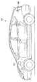
図1は、本発明の実施の形態に従う車両100の側面図である。図1を参照して、車両本体(ボデー)300には充電口200が形成される。充電口200には、商用電源から供給される電力を伝達するケーブルに接続されるコネクタ(図1に示さず)、および、そのコネクタに水や粉塵などが侵入するのを防止するための蓋204が設けられる。図1は充電口200が車両本体300の左側面かつ前輪側に形成された構成を示す。ただし充電口200を形成する位置は特に限定されるものではない。 FIG. 1 is a side view of
なお本実施の形態に従う車両100の車両本体(ボデー)には、内燃機関の作動に必要な燃料を給油するための給油口(図示しない)が形成されている。 In addition, a vehicle body (body) of
図2は、充電口200の外観図である。図2は蓋204が開かれた状態を示している。図2を参照して、充電口200は、車両本体300の車両外表面に形成された凹部である収容部208を含む。収容部208には充電コネクタ25が収容される。 FIG. 2 is an external view of the
蓋204は、支持部206によって回転可能に支持される。これによりユーザが蓋204を開閉できる。 The
次に、図3および図4を参照して、車両100の構成をより詳しく説明する。
図3は、車両100の概略構成図である。図3を参照して、車両100はパラレル/シリーズ式のハイブリッド自動車である。Next, the configuration of the
FIG. 3 is a schematic configuration diagram of the
車両100は、車両100の動作を制御するための制御部2と、車両100の駆動力を発生させるための電力を蓄える蓄電装置(BAT)4と、蓄電装置4に蓄積された電力を用いて車両100を駆動可能な駆動部30とを含む。駆動部30は、コンバータ(CONV)6と、主正母線MPLと、主負母線MNLと、コンデンサCと、第1インバータ(INV1)8−1と、第2インバータ(INV2)8−2と、モータジェネレータMG1と、モータジェネレータMG2と、内燃機関ENGと、動力分割機構22とを含む。
蓄電装置4は、充放電可能に構成された電力貯蔵要素である。蓄電装置4は、たとえば、リチウムイオン電池あるいはニッケル水素電池などの二次電池、電気二重層キャパシタなどの蓄電素子により構成される。 The power storage device 4 is a power storage element configured to be chargeable / dischargeable. The power storage device 4 is constituted by a power storage element such as a secondary battery such as a lithium ion battery or a nickel metal hydride battery, or an electric double layer capacitor.
コンバータ6は、蓄電装置4の入出力電圧と、主正母線MPL、主負母線MNL間の電圧とを相互に変換する。コンバータ6による電圧変換は制御部2からのスイッチング指令PWCに従って制御される。 Converter 6 mutually converts the input / output voltage of power storage device 4 and the voltage between main positive bus MPL and main negative bus MNL. The voltage conversion by the converter 6 is controlled according to the switching command PWC from the
コンデンサCは、主正母線MPL、主負母線MNL間の電圧を平滑化する。インバータ8−1,8−2はモータジェネレータMG1,MG2にそれぞれ対応して設けられる。インバータ8−1,8−2は、蓄電装置4に対して電気的に並列接続される。インバータ8−1,8−2は、直流電力と交流電力とを相互に変換する。 Capacitor C smoothes the voltage between main positive bus MPL and main negative bus MNL. Inverters 8-1 and 8-2 are provided corresponding to motor generators MG1 and MG2, respectively. Inverters 8-1 and 8-2 are electrically connected in parallel to power storage device 4. Inverters 8-1 and 8-2 mutually convert DC power and AC power.
車両100は、充電コネクタ25と、ACポート210と、電力線Lp,Ln,ACLp,ACLnとをさらに含む。
ACポート210は信号S1に応答して電力線Lpと電力線ACLpとを電気的に接続するとともに、電力線Lnと電力線ACLnとを電気的に接続する。制御部2は、電力線Lpと電力線ACLpとの電気的接続および電力線Lnと電力線ACLnとの電気的接続を制御するための信号S1を生成してACポート210に出力する。
ACポート210は電力線Lp,Lnにより充電コネクタ25に接続される。さらにACポート210は電力線ACLpおよびACLnによってモータジェネレータMG1の中性点N1およびモータジェネレータMG2の中性点N2に接続される。
モータジェネレータMG1およびMG2の各々は、U相コイル、V相コイル、W相コイルがY結線(星型結線)されたステータを備える。このY結線において3つのコイルが共通に接続される点がモータジェネレータMG1の中性点N1およびモータジェネレータMG2の中性点N2に対応する。 Each of motor generators MG1 and MG2 includes a stator in which a U-phase coil, a V-phase coil, and a W-phase coil are Y-connected (star-connected). In this Y connection, the point where the three coils are connected in common corresponds to neutral point N1 of motor generator MG1 and neutral point N2 of motor generator MG2.
外部電源240により蓄電装置4を充電する場合には、外部電源240からの電力は連結器250によって車両100に伝達される。連結器250は、プラグ260と、コネクタ261と、CCID(Charging Circuit Interrupt Device)262と、充電ケーブル263,264とを含む。充電ケーブル264は、電力線PSLp,PSLnを含む。 When charging power storage device 4 with
プラグ260は外部電源240に電気的に結合されたコネクタ241に接続される。コネクタ261は充電コネクタ25に接続される。これにより、電力線PSLp,Lp,ACLpが電気的に接続されるとともに、電力線PSLn,Ln,ACLnが電気的に接続される。
制御部2は、コネクタ261と充電コネクタ25とが接続されたことを示すケーブル接続信号PISWを受ける。制御部2は、ケーブル接続信号PISWの電圧レベルに基づいてコネクタ261が充電コネクタ25に接続されたことを検知する。
ここで、外部電源240の供給電力の電圧値、種類(直流または交流)は特に限定されるものではない。たとえば外部電源240として各家庭に供給される商用電源を用いることができる。本実施の形態においては、外部電源240は、単相交流の商用電源(その電圧値が100Vもしくは200V)である。 Here, the voltage value and type (direct current or alternating current) of the power supplied from the
CCID262は、充電ケーブル263,264の間に設けられる。CCID262は、充電ケーブル263と充電ケーブル264との電気的な接続/遮断を行なう。また、CCID262は、プラグ260がコネクタ241に接続された場合には、外部電源240から供給される電力によって動作する。そして、CCID262はパイロット信号CPLTを発生して、その発生したパイロット信号CPLTを制御部2に出力する。 The
なお、充電コネクタ25と制御部2との間には、パイロット信号CPLTを通信するための信号線、およびケーブル接続信号PISWを通信するための信号線が設けられる。制
御部2は、これらの信号線を介してパイロット信号CPLTおよびケーブル接続信号PISWを受ける。A signal line for communicating pilot signal CPLT and a signal line for communicating cable connection signal PISW are provided between charging
モータジェネレータMG1,MG2の中性点N1,N2に外部電源の電力が供給されることにより、インバータ8−1の交流側の各相に電力線PSLpの電圧が印加されるとともにインバータ8−2の交流側の各相に電力線PSLnの電圧が印加される。インバータ8−1,8−2はスイッチング指令PWM1,PWM2にそれぞれ応答してスイッチング動作を行なう。これによりインバータ8−1,8−2から主正母線MPLおよび主負母線MNLに所定の電圧値を有する直流電力が供給される。 When the power of the external power supply is supplied to neutral points N1 and N2 of motor generators MG1 and MG2, the voltage of power line PSLp is applied to each phase on the AC side of inverter 8-1 and AC of inverter 8-2 is supplied. The voltage of the power line PSLn is applied to each phase on the side. Inverters 8-1 and 8-2 perform switching operations in response to switching commands PWM1 and PWM2, respectively. Thus, DC power having a predetermined voltage value is supplied from inverters 8-1 and 8-2 to main positive bus MPL and main negative bus MNL.
より具体的には、インバータ8−1,8−2の各々は、交流側の3相分にそれぞれ対応する3つのアーム回路を有する。各アーム回路は、少なくとも1個のスイッチング素子を有する上アーム回路および下アーム回路を含む。 More specifically, each of inverters 8-1 and 8-2 has three arm circuits respectively corresponding to three phases on the AC side. Each arm circuit includes an upper arm circuit and a lower arm circuit having at least one switching element.
そして、インバータ8−1,8−2の各々において、各相に対応する上アーム回路を一括してオン/オフさせるとともに、各相に対応する下アーム回路についても同様に一括してオン/オフさせる。これによりインバータ8−1,8−2の各々において、3つの上アーム回路は互いに同じスイッチング状態(すべてオン、または、すべてオフ)とみなすことができる。同様に3つの下アーム回路も互いに同じスイッチング状態とみなすことができる。このようなスイッチング動作によって、それぞれの相電圧を互いに等しくできる。なお、このようなスイッチングモードは零相モードとも称される。 In each of inverters 8-1 and 8-2, the upper arm circuit corresponding to each phase is turned on / off at the same time, and the lower arm circuit corresponding to each phase is turned on / off in the same manner. Let Thereby, in each of inverters 8-1 and 8-2, the three upper arm circuits can be regarded as the same switching state (all on or all off). Similarly, the three lower arm circuits can be regarded as the same switching state. By such a switching operation, the respective phase voltages can be made equal to each other. Such a switching mode is also referred to as a zero-phase mode.
図4は、零相モード時におけるインバータ8−1,8−2およびモータジェネレータMG1,MG2の零相等価回路図である。図4を参照して、インバータ8−1,8−2が上述の零相モードに従ってスイッチング動作する場合には、インバータ8−1における3つの上アーム回路は上アームARM1pとしてまとめて示すことができ、インバータ8−1における3つの下アーム回路は下アームARM1nとしてまとめて示すことができる。上アームARM1pおよび下アームARM1nの各々は、スイッチング素子TRと還流ダイオードDとからなる。同様に、インバータ8−2における3つの上アーム回路は上アームARM2pとしてまとめて示すことができ、インバータ8−2における3つの下アーム回路は下アームARM2nとしてまとめて示すことができる。 FIG. 4 is a zero phase equivalent circuit diagram of inverters 8-1, 8-2 and motor generators MG1, MG2 in the zero phase mode. Referring to FIG. 4, when inverters 8-1, 8-2 perform switching operation according to the above-described zero phase mode, the three upper arm circuits in inverter 8-1 can be collectively shown as upper arm ARM1p. The three lower arm circuits in the inverter 8-1 can be collectively shown as the lower arm ARM1n. Each of the upper arm ARM1p and the lower arm ARM1n includes a switching element TR and a free wheel diode D. Similarly, the three upper arm circuits in the inverter 8-2 can be collectively shown as an upper arm ARM2p, and the three lower arm circuits in the inverter 8-2 can be collectively shown as a lower arm ARM2n.
図4に示される零相等価回路は、主正母線MPLおよび主負母線MNLを介して供給される直流電力を単相交流電力へ変換可能であるとともに、電力線ACLp,ACLnを介して中性点N1およびN2に入力される単相交流電力を直流電力へ変換可能な、単相インバータとみることができる。 The zero-phase equivalent circuit shown in FIG. 4 is capable of converting DC power supplied via the main positive bus MPL and the main negative bus MNL into single-phase AC power, and has a neutral point via the power lines ACLp and ACLn. It can be regarded as a single-phase inverter capable of converting single-phase AC power input to N1 and N2 into DC power.
すなわち、零相モードを実現できるようにインバータ8−1,8−2を制御することによって、インバータ8−1,8−2を単相インバータとして等価的に動作させることができる。これにより外部電源240から供給される単相交流電力を直流電力に変換し、かつその直流電力を主正母線MPL,主負母線MNLに供給することが可能になる。この直流電力によって、蓄電装置4が充電される。 That is, by controlling the inverters 8-1 and 8-2 so as to realize the zero-phase mode, the inverters 8-1 and 8-2 can be equivalently operated as a single-phase inverter. As a result, single-phase AC power supplied from
図3に戻り、車両100の構成について再び説明する。内燃機関ENGは燃料の燃焼によって作動する。モータジェネレータMG1は、内燃機関ENGからの動力の一部を受けて発電可能である。モータジェネレータMG2は、蓄電装置(BAT)4からの電力により電動機として作動する。 Returning to FIG. 3, the configuration of the
内燃機関ENGおよびモータジェネレータMG1,MG2は、動力分割機構22を介して、互いに機械的に結合されている。動力分割機構22は、代表的には遊星歯車機構によ
り構成される。Internal combustion engine ENG and motor generators MG1, MG2 are mechanically coupled to each other via
車両100の走行時には、インバータ8−1は、主として、制御部2からのスイッチング指令PWM1に応じて、モータジェネレータMG1で発生する交流電力を直流電力に変換する。インバータ8−2は、制御部2からのスイッチング指令PWM2に応じて、主正母線MPLおよび主負母線MNLを介して供給される直流電力を交流電力に変換して、その交流電力をモータジェネレータMG2に供給する。動力分割機構22は、内燃機関ENGの作動によって発生する駆動力を2分割し、その一方をモータジェネレータMG1側へ配分するとともに、残りをモータジェネレータMG2へ配分する。 When
動力分割機構22からモータジェネレータMG1へ配分された駆動力は発電動作に用いられる。モータジェネレータMG1により生成された電力は蓄電装置4の充電に用いられたり、モータジェネレータMG2による駆動力の発生に用いられたりする。モータジェネレータMG2へ配分された駆動力は、モータジェネレータMG2で発生した駆動力と合成されて、駆動輪24の駆動に用いられる。 The driving force distributed from
なお、蓄電装置の個数、容量は特に限定されるものではない。たとえば複数の蓄電装置が車両100に搭載されてもよい。蓄電装置4が外部電源240により充電された場合、蓄電装置4を十分に充電することができる。この場合には、内燃機関ENGを停止状態に維持したまま、モータジェネレータMG2で発生する駆動力のみを用いる走行、いわゆるEV(Electric Vehicle)走行が可能になる。たとえば蓄電装置の個数を増やすことによって多くの電力を蓄積することができるので、EV走行の距離を長くすることができる。 Note that the number and capacity of the power storage devices are not particularly limited. For example, a plurality of power storage devices may be mounted on
制御部2は、起動指示IGONに応じて、車両100が走行可能状態となるように、駆動部30を制御する。具体的には、制御部2は電流センサ10,14および電圧センサ12,16からの情報に基づいて、コンバータ6、インバータ8−1,8−2を制御する。電流センサ10は電力線PLに流れる電流(蓄電装置4に入出力される電流)である電流Ibatを検知する。電圧センサ12は、電力線PL,NLの間の電圧Vbatを検知する。電流センサ14は、主正母線MPLに流れる電流IDCを検知する。電圧センサ16は主正母線MPLと主負母線MNLとの間の電圧VDCを検知する。制御部2は電流Ibat,IDCの値および電圧Vbat,VDCの値を受けて、スイッチング指令PWM1,PWM2,PWCを出力する。 The
車速検出装置32は、車両100の速度SVを検出して、その検出値を制御部2へ出力する。 The vehicle
続いてCCID262についてより詳しく説明する。CCID262は、コネクタ261が充電コネクタ25に接続され、かつ、パイロット信号CPLTの電位が規定値に低下すると、規定のデューティー(発振周期に対するパルス幅の比)サイクルでパイロット信号CPLTを発振させる。このデューティーサイクルは、外部電源240から連結器250を介して車両100へ供給可能な定格電流に基づいて設定される。 Next, the
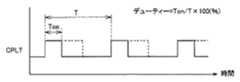
図5は、図3に示したCCID262によって発生されるパイロット信号CPLTの波形を示した図である。図5を参照して、パイロット信号CPLTは、規定の周期Tで発振する。パイロット信号CPLTのパルス幅Tonは、外部電源240から連結器250を介して車両100へ供給可能な定格電流に基づいて設定される。車両100に含まれる制御部2は、CCID262からパイロット信号CPLTを受ける。制御部2は、周期Tに対するパルス幅Tonの比で示されるデューティーにより定格電流の情報を取得する。 FIG. 5 shows a waveform of pilot signal CPLT generated by
定格電流は充電ケーブル毎に定められている。充電ケーブルの種類が異なれば、定格電
流が異なるためパイロット信号CPLTのデューティーも異なる。制御部2は、CCID262から送信されるパイロット信号CPLTをコントロールパイロット線(制御線)を介して受信し、その受信したパイロット信号CPLTのデューティーを検知する。これにより制御部2は、車両100に供給可能な定格電流を検知できる。すなわち、パイロット信号CPLTは車両100に供給される供給電力の情報を示す供給電力信号である。The rated current is determined for each charging cable. If the type of the charging cable is different, the rated current is different, so the duty of the pilot signal CPLT is also different. The
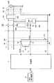
図6は、図3に示すCCID262の構成を説明する図である。図6を参照して、CCID262は、リレー332と、コントロールパイロット回路334と、電磁コイル606と、漏電検出器608とを含む。コントロールパイロット回路334は、発振器602と、抵抗R1と、電圧センサ604とを含む。 FIG. 6 is a diagram illustrating the configuration of
コネクタ241とプラグ260とが接続された場合、発振器602は、外部電源240から供給される電力を受ける。発振器602は、この電力により作動する。発振器602は、電圧センサ604によって検出されるパイロット信号CPLTの電位が規定の電位V1(たとえば12V)近傍のときは非発振の信号を出力し、パイロット信号CPLTの電位がV1から低下すると、規定の周波数(たとえば1kHz)およびデューティーサイクルで発振する信号を出力する。後述のように、パイロット信号CPLTの電位は、制御部2に含まれる抵抗回路の抵抗値を切替えることにより変更される。 When
コントロールパイロット回路334は、パイロット信号CPLTの電位が規定の電位V3(たとえば6V)近傍のとき、電磁コイル606へ電流を供給する。電磁コイル606は、コントロールパイロット回路334から電流が供給されると電磁力を発生し、リレー332をオン状態にする。コネクタ261が充電コネクタ25に接続され、かつリレー332がオン状態になったときには、外部電源240からプラグインハイブリッド車へ充電電力を供給するための電力線対が電力線Lp,Lnに電気的に接続される。
漏電検出器608は、外部電源240からプラグインハイブリッド車へ充電電力を供給するための電力線対に設けられ、漏電の有無を検出する。具体的には、漏電検出器608は、電力線対に互いに反対方向に流れる電流の平衡状態を検出し、その平衡状態が破綻すると漏電の発生を検知する。なお、特に図示しないが、漏電検出器608により漏電が検出されると、電磁コイル606への給電が遮断され、リレー332がオフされる。また、パイロット信号CPLTの電位は、規定の負電位(たとえば−12V)に固定される。
パイロット信号CPLTはコントロールパイロット回路334から端子T1に出力される。端子T1はコントロールパイロット線L1により制御部2に接続される。これによりコントロールパイロット回路334から出力されたパイロット信号CPLTは、コントロールパイロット線L1を介して制御部2に入力される。 Pilot signal CPLT is output from
コネクタ261にはスイッチ312が設けられる。スイッチ312は、端子T2と、接地ノードとの間に接続される。また、端子T2と制御部2とは信号線L2により接続される。コネクタ261が充電コネクタ25に接続されると、スイッチ312が作動する。これによりコネクタ261が充電コネクタ25に接続されたことを示すケーブル接続信号PISWが信号線L2を介して制御部2に入力される。なお制御部2の接地端子は接地線L3によって接地ノードに接続される。 The
制御部2は、車速検出装置32が検出した車両の速度SVをさらに受ける。
端子T1,T2の間には抵抗R2が接続される。充電コネクタ25がコネクタ261に接続された場合には、スイッチ312がオンすることにより端子T2が接地ノードに接続される。一方、充電コネクタ25がコネクタ261に接続されていない場合には、スイッチ312がオフすることにより端子T2が接地ノードと切り離され、かつ、端子T2の電
位は、接地電位よりも高い電位に設定される。これにより、本実施の形態では、コントロールパイロット線L1の断線を検出できる。さらに本実施の形態では、車両100が外部電源240に接続されていない場合、すなわち充電コネクタ25がコネクタ261に接続されていない場合にコントロールパイロット線L1の断線を検出できる。The
A resistor R2 is connected between the terminals T1 and T2. When charging
さらに、本実施の形態によれば、充電コネクタ25がコネクタ261に接続された場合において、コントロールパイロット線L1の電位変化の有無に基づいて電源側の異常を検出できる。なお「電源側の異常」とは、車両100への電力供給の異常を意味し、たとえばプラグ260とコネクタ241との非接続、外部電源240の停電が含まれる。 Furthermore, according to the present embodiment, when the charging
図7は、図3に示す制御部2の構成を説明する図である。図7を参照して、制御部2は、ダイオードD1,D2と、抵抗回路502と、電圧発生回路504と、負電圧検出回路506と、入力バッファ508,520と、CPU(Control Processing Unit)512,514,522,524と、サンプリング制御回路526とを含む。 FIG. 7 is a diagram illustrating the configuration of the
抵抗回路502は、プルダウン抵抗R3,R4と、スイッチSW1,SW2とを含む。プルダウン抵抗R3およびスイッチSW1は、パイロット信号CPLTが通信されるコントロールパイロット線L1と車両アース518との間に直列に接続される。プルダウン抵抗R4およびスイッチSW2は、コントロールパイロット線L1と車両アース518との間に直列に接続され、直列接続されたプルダウン抵抗R3およびスイッチSW1に並列に接続される。スイッチSW1,SW2は、CPU512からの制御信号に応じてオン/オフされる。
抵抗回路502は、CPU512からの制御信号に応じてスイッチSW1,SW2がオン/オフすることによりパイロット信号CPLTの電位を切替える。すなわち、スイッチSW1がオフし、かつ、CPU512からの制御信号に応じてスイッチSW2がオンした場合、プルダウン抵抗R4によってパイロット信号CPLTの電位は規定の電位V2(たとえば9V)に低下する。さらにCPU512からの制御信号に応じてスイッチSW1がオンすると、プルダウン抵抗R3,R4によってパイロット信号CPLTの電位は規定の電位V3(たとえば6V)に低下する。
電圧発生回路504は、電源ノード516と、プルアップ抵抗R5と、抵抗R6と、ダイオードD3とを含む。この電圧発生回路504は、コネクタ261が充電コネクタ25に接続されていないときに、プルアップ抵抗R5と、端子T1,T2間に接続される抵抗R2と、車両アース518に接続されるプルダウン抵抗R7とによって分圧された電圧をコントロールパイロット線L1に発生させる。
負電圧検出回路506は、パイロット信号CPLTの電位が規定の負電位(たとえば−12V)に固定されたことを検出し、その検出結果をCPU512に出力する。パイロット信号CPLTの電位が規定の負電位に固定される場合とは、漏電検出器608(図6参照)により漏電が検出された場合である。なお、負電圧検出回路506による負電位の検出方法は特に限定されるものではない。 The negative
入力バッファ508は、コントロールパイロット線L1のパイロット信号CPLTを受け、その受けたパイロット信号CPLTをCPU512へ出力する。
電圧発生回路504は信号線L2を介してケーブル接続信号PISWを受ける。電圧発生回路504はケーブル接続信号PISWに応じた信号を出力する。入力バッファ520は、電圧発生回路504からの信号を受けて、その信号をCPU522へ出力する。
コネクタ261が充電コネクタ25に接続された場合、スイッチ312がオンすることによって、信号線L2の電位は接地レベルとなる。一方、コネクタ261が充電コネクタ25に接続されていない場合には、スイッチ312がオフすることにより、信号線L2の電位は、接地レベルより高い第1の電位となる。すなわちケーブル接続信号PISWは、コネクタ261が充電コネクタに接続されているときL(論理ロー)レベルとなり、非接続時はH(論理ハイ)レベルとなる信号である。 When the
ケーブル接続信号PISWがLレベルのときには、入力バッファ520にLレベルの信号が入力され、ケーブル接続信号PISWがHレベルのときには入力バッファ520にHレベルの信号が入力される。CPU522は、Lレベルの信号を受けた場合に、コネクタ261が充電コネクタ25に接続されたと判定する。 When the cable connection signal PISW is at L level, an L level signal is input to the
なお、信号線L2が断線した場合、入力バッファ520に入力される信号の電位は、上記の第1の電位よりも高い第2の電位となる。CPU522は、入力バッファ520から受ける信号の電位が第2の電位である場合には、信号線L2が断線したと判定する。 Note that when the signal line L2 is disconnected, the potential of the signal input to the
CPU522はCPU524により起動されるまで停止している。また、CPU512はCPU514により起動されるまで停止している。CPU524は、コネクタ261が充電コネクタ25に接続されたことを検知した場合にCPU522を起動する。CPU514はCPU522の起動に応じてCPU512を起動する。 The
CPU524は、サンプリング制御回路526を制御することにより、サンプリング制御回路526にスイッチSW3を繰り返しオン/オフさせるための制御信号を出力させる。なお、スイッチSW3のオン期間あるいはスイッチSW3がオンするタイミングは特に限定されるものではない。 The
コネクタ261が充電コネクタ25に接続されていない場合、CPU524に入力される信号SINの電位は、スイッチSW3のオン時においてノード515の電位B2に等しくなり、スイッチSW3のオフ時においてノード514の電位B1に等しくなる。一方、コネクタ261が充電コネクタ25に接続された場合、スイッチSW3のオン/オフによらずに信号SINの電位は接地レベルに低下する。CPU524は、信号SINの電位が接地レベルであることを検知すると、コネクタ261が充電コネクタ25に接続されたと判定しCPU522を起動する。 When the
CPU522は、CPU524により起動されると、入力バッファ520から信号を受ける。CPU522は、入力バッファ520からの信号がLレベルのときには、コネクタ261が充電コネクタ25に接続されたと判定する。 When the
CPU514は、CPU522の状態を監視して、CPU522がCPU524により起動されるとCPU512を起動する。 The
CPU512は、CPU514により起動されると、入力バッファ508からパイロット信号CPLTを受ける。さらに、CPU512は、CPU522から、充電コネクタ25にコネクタ261が接続されたとの判定結果を受けると、スイッチSW2へ出力される制御信号を活性化する。その後、CPU512は、スイッチSW2のオンに応じて発振が開始されたパイロット信号CPLTに基づいて、外部電源240から車両100に供給可能な定格電流を検出する。 When activated by
定格電流が検出され、外部電源240から蓄電装置4の充電準備が完了すると、CPU512は、スイッチSW1へ出力される制御信号をさらに活性化し、図3に示すACポー
ト210に信号S1を送る。これにより、図3に示されるように、外部電源240からの交流電力がモータジェネレータMG1の中性点N1およびモータジェネレータMG2の中性点N2に与えられ(いずれも図示せず)、蓄電装置4の充電制御が実行される。When the rated current is detected and preparation for charging of power storage device 4 from
CPU512は、充電コネクタ25にコネクタ261が接続された状態において、電源側から供給される電力の供給異常の有無を判定する。後に詳細に説明するが、CPU512は、パイロット信号CPLTの電位変化の有無に基づいて、電力の供給異常の有無を判定する。 The
CPU512は、充電コネクタ25にコネクタ261が接続されていない状態において、コントロールパイロット線L1が断線しているか否かを判定する。具体的には、CPU512は、車速検出装置32(図3参照)が検出した車両100の速度SVが0と異なる場合においてコントロールパイロット線L1が断線しているか否かを判定する。 The
速度SVが0と異なる場合とは、車両100が走行している場合である。車両100が外部電源240により充電される場合、車両100は停車しているものと考えられる。言い換えると、車両100が走行している場合には車両100が外部電源に接続されていないと考えられる。したがって、CPU512は、速度SVが0より大きい場合においてコントロールパイロット線L1が断線しているか否かを判定する。これにより正確な断線検出が可能になる。 The case where the speed SV is different from 0 is a case where the
なお、CPU512が起動され、かつ、充電コネクタ25にコネクタ261が接続されていないという条件が満たされるのであれば、CPU512はコントロールパイロット線L1の断線を検出できる。本実施の形態では車両の走行中にコントロールパイロット線の断線検出が実行されるが、上記の条件が満たされる限りにおいて、CPU512がコントロールパイロット線L1の断線を検出するタイミングは特に限定されるものではない。 If the condition that the
CPU512は、充電コネクタ25にコネクタ261が接続された状態において電源側の異常を判定し、充電コネクタ25にコネクタ261が接続されていない状態においてコントロールパイロット線L1が断線しているか否かを判定する。これにより本実施の形態では、コントロールパイロット線L1の断線と電源側の異常とを区別することができる。 The
続いてCPU512によるコントロールパイロット線L1の断線検出について説明する。プルアップ抵抗R5と、抵抗R2と、プルダウン抵抗R7とは、電源ノード516と、車両アース518との間に設けられる分圧回路を構成する。コネクタ261が充電コネクタ25に接続されず、かつ、コントロールパイロット線L1が断線していない場合、コントロールパイロット線L1には、プルアップ抵抗R5と、抵抗R2と、プルダウン抵抗R7により分圧された電圧が与えられる。これによりコントロールパイロット線L1の電位が接地電位より高くなる。つまりコントロールパイロット線L1の電位はHレベルになる。 Next, detection of disconnection of the control pilot line L1 by the
一方、コントロールパイロット線L1が断線している場合、コントロールパイロット線L1に生じる電位はほぼ接地レベルとなる。つまりコントロールパイロット線L1の電位はLレベルになる。 On the other hand, when the control pilot line L1 is disconnected, the potential generated on the control pilot line L1 is substantially at the ground level. That is, the potential of the control pilot line L1 becomes L level.
より具体的に説明すると、車両100が連結器250に接続された場合には、端子T2(抵抗R2の一端)の電位がスイッチ312によって車両アース電位に設定される。一方、車両100が連結器250に接続されていない場合には、スイッチ312は、端子T2を車両アース電位から切り離す。電圧発生回路504は車両100が連結器250に接続されていない場合に端子T2の電位を車両アース電位よりも高い電位に設定(プルアップ
)する。More specifically, when the
このようにコントロールパイロット線L1が正常である場合と、コントロールパイロット線L1が断線している場合とで、コントロールパイロット線L1の電位レベルが異なるので、コントロールパイロット線L1の断線検出が可能になる。CPU512は、コントロールパイロット線L1の電位がLレベルであればコントロールパイロット線L1が断線したと判定し、コントロールパイロット線L1の電位がHレベルであればコントロールパイロット線L1が正常であると判定する。 Thus, since the potential level of the control pilot line L1 differs between when the control pilot line L1 is normal and when the control pilot line L1 is disconnected, it is possible to detect disconnection of the control pilot line L1. The
抵抗R2の抵抗値は、抵抗回路502でのパイロット信号CPLTの電位の変更に影響を与えない値に設定されることが好ましい。電位V1〜V3をそれぞれ12V,9V,6Vに設定するために、たとえばプルダウン抵抗R3,R4の抵抗値がそれぞれ1.3(kΩ),2.74(kΩ)であるとする。抵抗R2の抵抗値は、たとえばこれらの抵抗値に比べて十分に大きな値(たとえば100kΩ程度)に設定される。 The resistance value of the resistor R2 is preferably set to a value that does not affect the change of the potential of the pilot signal CPLT in the
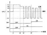
図8は、充電開始時におけるパイロット信号CPLTおよびスイッチSW1,SW2のタイミングチャートである。図6から図8を参照して、時刻t1において、連結器250のプラグ260が外部電源240のコネクタ241に接続されると、外部電源240からの電力を受けてコントロールパイロット回路334がパイロット信号CPLTを生成する。 FIG. 8 is a timing chart of pilot signal CPLT and switches SW1 and SW2 at the start of charging. 6 to 8, when plug 260 of
この時点では、連結器250のコネクタ261は車両100側の充電コネクタ25に接続されていない。このため、パイロット信号CPLTの電位はV1(たとえば12V)であり、パイロット信号CPLTは非発振状態である。 At this time, the
時刻t2において、コネクタ261が充電コネクタ25に接続される。ケーブル接続信号PISWに基づいてコネクタ261と充電コネクタ25との接続が検出される。これによりスイッチSW2がオンされる。スイッチSW2がオンすると、抵抗回路502のプルダウン抵抗R3によってパイロット信号CPLTの電位はV2(たとえば9V)に低下する。 The
パイロット信号CPLTの電位がV2に低下すると、時刻t3において、コントロールパイロット回路334がパイロット信号CPLTを発振させる。そして、CPU512においてパイロット信号CPLTのデューティーに基づき定格電流が検出され、充電制御の準備がなされる。充電制御の準備が完了すると、時刻4において、スイッチSW1がオンされる。スイッチSW1がオンすると、抵抗回路502のプルダウン抵抗R3によってパイロット信号CPLTの電位はV3(たとえば6V)にさらに低下する。 When the potential of pilot signal CPLT drops to V2,
パイロット信号CPLTの電位がV3に低下すると、コントロールパイロット回路334から電磁コイル606へ電流が供給され、CCID330のリレー332がオンされる。その後は、ACポート210がオンされ、蓄電装置4の充電が実行される。 When the potential of pilot signal CPLT drops to V3, a current is supplied from
上述した説明は、電源側の電力供給が正常な場合のパイロット信号CPLTの変化である。停電あるいは、外部電源240とコネクタ261との非接続など、電源側の電力供給の異常が生じた場合には、スイッチ312がオンし、かつ、端子T1が抵抗R2および端子T2を介してスイッチに接続されているため、コントロールパイロット線L1の電位は0Vのまま変化しない。 The above description is a change in pilot signal CPLT when the power supply on the power supply side is normal. When a power supply abnormality such as a power failure or disconnection between the
したがって、CPU512は、コネクタ261が充電コネクタ25に接続された時点から所定の時間、コントロールパイロット線L1の電位が0Vのまま変化しない場合には、
車両に供給される電力の供給異常が生じたと判定する。一方、CPU512は、コネクタ261が充電コネクタ25に接続され、かつ、コントロールパイロット線L1の電位が変化する場合には、車両に電力が正常に供給されていると判定する。Therefore, when the potential of the control pilot line L1 remains 0V for a predetermined time from when the
It is determined that an abnormality in the supply of electric power supplied to the vehicle has occurred. On the other hand,
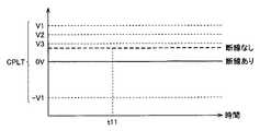
図9は、コントロールパイロット線L1の断線検出時におけるパイロット信号CPLTを示す図である。図9および図7を参照して、時刻t11以前において、連結器250のコネクタ261は、車両側の充電コネクタ25から外されているものとする。時刻t11において走行が開始され車両速度SVが0でなくなると、CPU512はコントロールパイロット線L1の断線の有無を判定する。 FIG. 9 is a diagram showing pilot signal CPLT when disconnection of control pilot line L1 is detected. 9 and 7, it is assumed that
コントロールパイロット線L1の断線がなければ、パイロット信号CPLTの電位は低下せず、0Vより高い状態に保たれる。すなわちパイロット信号CPLTはHレベルに保たれる。一方、コントロールパイロット線L1に断線が発生しているとパイロット信号CPLTの電位は接地レベル(略0V)に低下するのでパイロット信号CPLTはLレベルになる。したがって、CPU512は、パイロット信号CPLTがLレベルに低下したことを検出することにより、コントロールパイロット線L1の断線を検出することができる。 If the control pilot line L1 is not disconnected, the potential of the pilot signal CPLT is not lowered and is kept higher than 0V. That is, pilot signal CPLT is kept at the H level. On the other hand, if disconnection occurs in control pilot line L1, the potential of pilot signal CPLT drops to the ground level (approximately 0 V), so pilot signal CPLT goes to L level. Therefore,
なお、本実施の形態において、車両100は、蓋204の開閉状態を検出する検出装置をさらに備えてもよい。この場合、CPU512は、その検出装置によって蓋204が閉状態であることが検出され、かつ、車両の速度SVが0と異なる場合に、コントロールパイロット線L1の断線の有無を判定してもよい。蓋204が閉状態であり、かつ、車両速度SVが0でないことを条件として断線検出が実施されるため、パイロット信号CPLTが制御に用いられる充電時に断線検出が実施されるのを確実に防止することができる。よって、断線検出を正確に行なうことが可能になる。 In the present embodiment,
今回開示された実施の形態はすべての点で例示であって制限的なものではないと考えられるべきである。本発明の範囲は、上記した実施の形態の説明ではなくて特許請求の範囲によって示され、特許請求の範囲と均等の意味および範囲内でのすべての変更が含まれることが意図される。 The embodiment disclosed this time should be considered as illustrative in all points and not restrictive. The scope of the present invention is shown not by the above description of the embodiments but by the scope of claims for patent, and is intended to include meanings equivalent to the scope of claims for patent and all modifications within the scope.
2 制御部、4 蓄電装置、6 コンバータ、8−1,8−2 インバータ、10,14 電流センサ、12,16,604 電圧センサ、22 動力分割機構、24 駆動輪、25 充電コネクタ、30 駆動部、32 車速検出装置、100 車両、200 充
電口、204 蓋、206 支持部、208 収容部、210 ACポート、240 外部電源、241 コネクタ、250 連結器、260 プラグ、261 コネクタ、263,264 充電ケーブル、300 車両本体(ボデー)、312 スイッチ、332 リレー、334 コントロールパイロット回路、502 抵抗回路、504 電圧発生回路、506 負電圧検出回路、508,520 入力バッファ、512,514,522,524 CPU、514,515 ノード、516 電源ノード、518 車両アース、526 サンプリング制御回路、602 発振器、606 電磁コイル、608 漏電検出器、ACLp,ACLn,Lp,Ln,PL,NL,PSLp,PSLn 電力線、ARM1n,ARM2n 下アーム、ARM1p,ARM2p 上アーム、C コンデンサ、D 還流ダイオード、D1〜D3 ダイオード、ENG 内燃機関、L1 コントロールパイロット線、L2 信号線、L3 接地線、MG1,MG2 モータジェネレータ、MNL 主負母線、MPL 主正母線、N1,N2 中性点、R1,R2,R6 抵抗、R3,R4,R7 プルダウン抵抗、R5 プルアップ抵抗、SW1〜SW3 スイッチ、T1,T2 端子、TR スイッチング素子。2 Control unit, 4 Power storage device, 6 Converter, 8-1, 8-2 Inverter, 10, 14 Current sensor, 12, 16, 604 Voltage sensor, 22 Power split mechanism, 24 Drive wheel, 25 Charging connector, 30 Drive unit , 32 Vehicle speed detection device, 100 vehicle, 200 charging port, 204 lid, 206 support part, 208 housing part, 210 AC port, 240 external power supply, 241 connector, 250 coupler, 260 plug, 261 connector, 263, 264 , 300 Vehicle body (body), 312 switch, 332 relay, 334 control pilot circuit, 502 resistance circuit, 504 voltage generation circuit, 506 negative voltage detection circuit, 508, 520 input buffer, 512, 514, 522, 524 CPU, 514 , 515 nodes, 516 power supply nodes, 518 vehicles 526, sampling control circuit, 602 oscillator, 606 electromagnetic coil, 608 leakage detector, ACLp, ACLn, Lp, Ln, PL, NL, PSLp, PSLn power line, ARM1n, ARM2n lower arm, ARM1p, ARM2p upper arm, C Capacitor, D freewheeling diode, D1-D3 diode, ENG internal combustion engine, L1 control pilot line, L2 signal line, L3 ground line, MG1, MG2 motor generator, MNL main negative bus, MPL main positive bus, N1, N2 neutral point , R1, R2, R6 resistors, R3, R4, R7 pull-down resistors, R5 pull-up resistors, SW1 to SW3 switches, T1, T2 terminals, TR switching elements.
Claims (4)
Translated fromJapanese前記供給電力信号を通信するための制御線と、
前記制御線に、その一方端が接続される抵抗と、
前記車両が前記連結器に接続された場合には、前記抵抗の他方端の電位を第1の電位に設定し、前記車両が前記連結器に接続されていない場合には、前記抵抗の前記他方端の電位を、前記第1の電位よりも高い第2の電位に設定する電位設定回路と、
前記車両が前記連結器に接続されていない場合において、前記制御線の電位に基づいて前記制御線の断線検出を行なう異常検出部とを備える、車両の充電制御装置。When connected to a vehicle equipped with a power storage device for driving the vehicle and a power supply external to the vehicle, a coupler that outputs a supply power signal indicating information of supply power supplied to the vehicle, A charge control device capable of charging the power storage device with the supplied power in a state where a power source is connected,
A control line for communicating the supply power signal;
A resistor having one end connected to the control line;
When the vehicle is connected to the coupler, the potential at the other end of the resistor is set to a first potential, and when the vehicle is not connected to the coupler, the other end of the resistor is set. A potential setting circuit for setting a potential at an end to a second potential higher than the first potential;
A vehicle charge control device comprising: an abnormality detection unit configured to detect disconnection of the control line based on a potential of the control line when the vehicle is not connected to the coupler.
前記車両の充電口に設けられ、かつ、前記連結器に接続可能に構成された充電コネクタをさらに備え、
前記充電コネクタは、前記制御線が接続されるとともに前記供給信号を受ける端子を含み、
前記第1の電位は、車両アース電位であり、
前記電位設定回路は、
前記充電コネクタが前記連結器に接続されたときに、前記抵抗の前記他方端を前記車両アース電位に電気的に接続し、前記充電コネクタが前記連結器に接続されていないときに、前記抵抗の前記他方端を前記車両アース電位から切り離す接続回路と、
前記充電コネクタが前記連結器に接続されていないときに、前記抵抗の前記他方端の電位を前記第2の電位にプルアップするプルアップ回路とを含む、請求項1に記載の車両の充電制御装置。The charge control device includes:
A charging connector provided at a charging port of the vehicle and configured to be connectable to the coupler;
The charging connector includes a terminal connected to the control line and receiving the supply signal,
The first potential is a vehicle ground potential;
The potential setting circuit includes:
When the charging connector is connected to the coupler, the other end of the resistor is electrically connected to the vehicle ground potential, and when the charging connector is not connected to the coupler, A connection circuit for disconnecting the other end from the vehicle ground potential;
The vehicle charging control according to claim 1, further comprising: a pull-up circuit that pulls up the potential of the other end of the resistor to the second potential when the charging connector is not connected to the coupler. apparatus.
前記車両の速度を検出する車両速度検出装置をさらに備え、
前記異常検出部は、前記車両速度検出装置により前記車両の速度が0と異なることが検出された場合に、前記車両が前記連結器に接続されていないと判断するとともに前記断線検出を行なう、請求項2に記載の車両の充電制御装置。The charge control device includes:
A vehicle speed detecting device for detecting the speed of the vehicle;
The abnormality detection unit determines that the vehicle is not connected to the coupler and detects the disconnection when the vehicle speed detection device detects that the vehicle speed is different from 0. Item 3. The vehicle charge control device according to Item 2.
Priority Applications (3)
| Application Number | Priority Date | Filing Date | Title |
|---|---|---|---|
| JP2007275003AJP4375472B2 (en) | 2007-10-23 | 2007-10-23 | Vehicle charging control device |
| US12/285,408US7688024B2 (en) | 2007-10-23 | 2008-10-03 | Charge control device for vehicle |
| CN2008101667375ACN101420132B (en) | 2007-10-23 | 2008-10-23 | Charging control equipment for vehicle |
Applications Claiming Priority (1)
| Application Number | Priority Date | Filing Date | Title |
|---|---|---|---|
| JP2007275003AJP4375472B2 (en) | 2007-10-23 | 2007-10-23 | Vehicle charging control device |
Publications (2)
| Publication Number | Publication Date |
|---|---|
| JP2009106053A JP2009106053A (en) | 2009-05-14 |
| JP4375472B2true JP4375472B2 (en) | 2009-12-02 |
Family
ID=40562819
Family Applications (1)
| Application Number | Title | Priority Date | Filing Date |
|---|---|---|---|
| JP2007275003AExpired - Fee RelatedJP4375472B2 (en) | 2007-10-23 | 2007-10-23 | Vehicle charging control device |
Country Status (3)
| Country | Link |
|---|---|
| US (1) | US7688024B2 (en) |
| JP (1) | JP4375472B2 (en) |
| CN (1) | CN101420132B (en) |
Families Citing this family (76)
| Publication number | Priority date | Publication date | Assignee | Title |
|---|---|---|---|---|
| EP2234238A1 (en)* | 2008-01-11 | 2010-09-29 | Toyota Jidosha Kabushiki Kaisha | Vehicle charge control apparatus and vehicles |
| JP4332861B2 (en)* | 2008-01-16 | 2009-09-16 | トヨタ自動車株式会社 | Vehicle charging control device |
| JP4726939B2 (en) | 2008-09-26 | 2011-07-20 | 富士通テン株式会社 | Control system, control device, and cable connection state determination method |
| US9614389B2 (en)* | 2009-04-14 | 2017-04-04 | Ford Global Technologies, Llc | Method and system for controlling current flow through a power distribution circuit |
| US8653788B2 (en) | 2009-06-24 | 2014-02-18 | Toyota Jidosha Kabushiki Kaisha | Charging cable and charging system for electrically powered vehicle |
| US9199538B2 (en) | 2009-06-24 | 2015-12-01 | Toyota Jidosha Kabushiki Kaisha | Charge controller for electrically powered vehicle configured to allow charging of a power storage device for driving the vehicle from a power source outside of the vehicle |
| CN102470766B (en)* | 2009-07-03 | 2014-11-12 | 丰田自动车株式会社 | Electric vehicle |
| US9132741B2 (en)* | 2009-10-08 | 2015-09-15 | Ford Global Technologies, Llc | Method and system for controlling current flow through a power distribution circuit |
| DE102009045639A1 (en)* | 2009-10-13 | 2011-04-14 | Robert Bosch Gmbh | Electrical connection device for hybrid and electric vehicles and associated method for charging |
| EP2520456B1 (en)* | 2009-12-28 | 2019-02-27 | Toyota Jidosha Kabushiki Kaisha | Vehicle |
| EP2557746B1 (en)* | 2010-04-09 | 2020-05-06 | Toyota Jidosha Kabushiki Kaisha | Communication device, communication system, and vehicle |
| US8855951B2 (en)* | 2010-04-13 | 2014-10-07 | Ford Global Technologies, Llc | Power distribution circuit diagnostic system and method |
| WO2011142004A1 (en) | 2010-05-12 | 2011-11-17 | トヨタ自動車株式会社 | Vehicle and vehicle control method |
| US8841881B2 (en) | 2010-06-02 | 2014-09-23 | Bryan Marc Failing | Energy transfer with vehicles |
| JP5728831B2 (en)* | 2010-06-03 | 2015-06-03 | 株式会社豊田自動織機 | Charger |
| JP5488220B2 (en)* | 2010-06-09 | 2014-05-14 | 日産自動車株式会社 | Charge control apparatus and method |
| JP2011259658A (en)* | 2010-06-11 | 2011-12-22 | Toyota Motor Corp | Vehicular charging system and motor-driven vehicle |
| JP2012034484A (en)* | 2010-07-30 | 2012-02-16 | Toyota Industries Corp | Power supply device and vehicle |
| US8981716B2 (en)* | 2010-08-09 | 2015-03-17 | Control Module, Inc. | Power share system for electric vehicle service equipment |
| JP5171912B2 (en) | 2010-09-24 | 2013-03-27 | 三菱電機株式会社 | Power system |
| DE102010048385A1 (en)* | 2010-10-13 | 2012-04-19 | Audi Ag | Device for connecting a vehicle to a socket |
| DE102010063790A1 (en)* | 2010-12-21 | 2012-06-21 | Bayerische Motoren Werke Aktiengesellschaft | Charging station for e.g. charging energy storage of electric vehicle, has communication interface communicating charging parameter and/or monitoring parameter, where station produces and changes parameter based on preset requirements |
| US8432175B2 (en) | 2010-12-27 | 2013-04-30 | Lear Corporation | System and method for evaluating vehicle charging circuits |
| EP2667207B1 (en) | 2011-01-18 | 2021-03-31 | Nissan Motor Co., Ltd | Charging apparatus and method for determining conduction state |
| FR2971103B1 (en)* | 2011-01-28 | 2013-01-11 | Peugeot Citroen Automobiles Sa | FIXED MAXIMUM CURRENT LOAD SYSTEM FOR ELECTRIC OR HYBRID VEHICLES |
| WO2012149568A1 (en)* | 2011-04-29 | 2012-11-01 | Aerovironment, Inc. | Positive biased pilot filter for electric vehicle supply equipment |
| FR2977087B1 (en) | 2011-06-21 | 2013-07-05 | Peugeot Citroen Automobiles Sa | SECURE LOAD SYSTEM OF AN ELECTRIC OR HYBRID VEHICLE |
| JP5931864B2 (en) | 2011-06-21 | 2016-06-08 | 住友電気工業株式会社 | Communication system and communication apparatus |
| JP5876484B2 (en) | 2011-07-13 | 2016-03-02 | 住友電気工業株式会社 | Communications system |
| WO2013008903A1 (en) | 2011-07-13 | 2013-01-17 | 住友電気工業株式会社 | Communication system and communication apparatus |
| EP2733861A4 (en) | 2011-07-13 | 2016-07-13 | Sumitomo Electric Industries | COMMUNICATION SYSTEM AND DEVICE |
| US8669737B2 (en)* | 2011-08-29 | 2014-03-11 | GM Global Technology Operations LLC | Courtesy light for an electrical charging system |
| JP5123419B1 (en) | 2011-08-30 | 2013-01-23 | トヨタ自動車株式会社 | Connector for power feeding from vehicle to external power-supplied device, method for identifying the connector, identification system for the connector, power feeding system using the connector, and vehicle capable of power feeding in the system |
| JP5758746B2 (en) | 2011-08-30 | 2015-08-05 | トヨタ自動車株式会社 | Power supply connector, vehicle, and vehicle control method |
| US8466656B2 (en) | 2011-09-09 | 2013-06-18 | General Electric Company | Charging devices and methods for charging electrically powered vehicles |
| JP5835152B2 (en)* | 2011-09-16 | 2015-12-24 | 日立金属株式会社 | Vehicle charging device |
| JP5099279B1 (en)* | 2011-10-17 | 2012-12-19 | トヨタ自動車株式会社 | Power supply connector, vehicle, and method for recognizing power supply connector |
| JP5852404B2 (en) | 2011-10-21 | 2016-02-03 | 株式会社ケーヒン | Electronic control unit |
| JP5960966B2 (en)* | 2011-10-21 | 2016-08-02 | 株式会社ケーヒン | Electronic control unit |
| CA2792310C (en)* | 2011-10-21 | 2019-06-04 | Keihin Corporation | Electronic control unit |
| US8749198B2 (en)* | 2011-11-10 | 2014-06-10 | Lear Corporation | Control pilot detection circuit |
| US8506315B2 (en) | 2011-11-17 | 2013-08-13 | Schneider Electric USA, Inc. | Docking station for connector for electric vehicle charging station |
| US9421876B2 (en) | 2011-12-09 | 2016-08-23 | Honda Motor Co., Ltd. | Electric vehicle charging apparatus |
| DE102011056501B4 (en) | 2011-12-15 | 2025-10-16 | Dr. Ing. H.C. F. Porsche Aktiengesellschaft | Charging cable detection |
| CN103187777B (en) | 2011-12-28 | 2016-04-27 | 比亚迪股份有限公司 | A kind of charger and detection method |
| CN104054000B (en) | 2012-01-12 | 2016-12-14 | 艾里逊变速箱公司 | The system and method detected for the high voltage cable of hybrid electric vehicle |
| EP2817645B1 (en) | 2012-02-17 | 2021-04-07 | Allison Transmission, Inc. | High voltage cable detection using rotating machine in hybrid vehicles |
| WO2013129038A1 (en)* | 2012-02-28 | 2013-09-06 | 住友電気工業株式会社 | Communication system, communication device, power-supply device and vehicle |
| JP5751201B2 (en)* | 2012-03-29 | 2015-07-22 | 株式会社オートネットワーク技術研究所 | Power supply |
| DE102012007906A1 (en)* | 2012-04-23 | 2013-10-24 | Audi Ag | Method for preparing a power supply of a vehicle |
| US9333864B2 (en) | 2012-05-31 | 2016-05-10 | Lear Corporation | Wake-by-control pilot circuit for onboard battery charger |
| DE102012013405A1 (en) | 2012-07-05 | 2014-01-09 | Audi Ag | Diagnostic device for checking a control signal line |
| JP5790884B2 (en) | 2012-08-01 | 2015-10-07 | トヨタ自動車株式会社 | External power supply connector, vehicle and external power supply system |
| CN102866700B (en)* | 2012-08-15 | 2015-06-10 | 中国电力科学研究院 | Control guide tester for connecting device of electric vehicle and alternating-current charging pile and implementing method for control guide tester |
| JP5712983B2 (en) | 2012-08-23 | 2015-05-07 | トヨタ自動車株式会社 | Vehicle and vehicle control method |
| KR101481243B1 (en) | 2012-12-28 | 2015-01-09 | 현대자동차주식회사 | System and method for incipient drive of battery charger for green car |
| DE102013004638A1 (en)* | 2013-03-16 | 2014-09-18 | Volkswagen Aktiengesellschaft | Circuit and method for signal transmission |
| DE102013005072B3 (en)* | 2013-03-22 | 2014-09-04 | Volkswagen Aktiengesellschaft | Method and device for checking a control pilot line |
| EP2991188B1 (en)* | 2013-04-24 | 2023-07-26 | Panasonic Intellectual Property Management Co., Ltd. | Power conversion system, and connector |
| JP5900436B2 (en) | 2013-08-22 | 2016-04-06 | 株式会社デンソー | In-vehicle battery charger |
| DE102014013870B4 (en)* | 2014-09-18 | 2025-03-20 | TÜV Rheinland Industrie Service GmbH | Mobile testing system for automotive charging stations |
| DE102015214543A1 (en)* | 2015-07-30 | 2017-02-02 | Continental Automotive Gmbh | Method for safely charging a plug-in vehicle |
| KR20170019042A (en)* | 2015-08-11 | 2017-02-21 | 현대자동차주식회사 | Charging device for eco-friendly vehicle |
| TWI595722B (en)* | 2016-05-18 | 2017-08-11 | 台達電子工業股份有限公司 | Charge gun and electric vehicle supply equipment |
| US9855901B1 (en)* | 2016-08-24 | 2018-01-02 | Ford Global Technologies Llc | Flange for exterior ornamentation |
| JP6642338B2 (en)* | 2016-08-30 | 2020-02-05 | トヨタ自動車株式会社 | vehicle |
| JP6978380B2 (en) | 2018-06-01 | 2021-12-08 | トヨタ自動車株式会社 | Charge management system |
| CN112638719A (en) | 2018-09-26 | 2021-04-09 | 株式会社杰士汤浅国际 | Detection device and detection method |
| KR102789573B1 (en)* | 2019-08-30 | 2025-04-01 | 현대자동차주식회사 | System and method for charging using motor driving system |
| US11458849B2 (en)* | 2020-03-23 | 2022-10-04 | Ford Global Technologies, Llc | Charging input selector systems for electrified vehicles |
| US11802919B2 (en)* | 2020-11-23 | 2023-10-31 | Rivian Ip Holdings, Llc | Systems and methods for remotely testing continuity of electrical wiring |
| US11881659B2 (en)* | 2021-08-20 | 2024-01-23 | Beta Air, Llc | Connector and methods of use for charging an electric vehicle |
| TWI849402B (en)* | 2022-04-08 | 2024-07-21 | 飛宏科技股份有限公司 | Detection circuitry for control piot abnormality of a dc charging pile |
| FR3136557B1 (en)* | 2022-06-10 | 2024-06-21 | Delta Dore | DEVICE FOR DETECTING A CUTTING AND/OR AN ANOMALY OF A CONNECTION |
| EP4303062A1 (en)* | 2022-07-08 | 2024-01-10 | Aptiv Technologies Limited | Vehicle charging diagnostic apparatus, method, and software |
| DE102023212902A1 (en)* | 2023-12-18 | 2025-06-18 | Robert Bosch Gesellschaft mit beschränkter Haftung | Connector, device connected to a connector, method for operating a device with an energy storage device and method for establishing a connection between a connector and a device |
Family Cites Families (6)
| Publication number | Priority date | Publication date | Assignee | Title |
|---|---|---|---|---|
| JPH02146937A (en) | 1988-11-25 | 1990-06-06 | Toyota Motor Corp | electric car charger |
| US5369352A (en) | 1993-04-26 | 1994-11-29 | Ford Motor Company | Universal electric vehicle charging adapter |
| JP4024420B2 (en) | 1999-03-17 | 2007-12-19 | アイシン・エィ・ダブリュ株式会社 | Abnormality detection device and abnormality detection method |
| JP2000354332A (en) | 1999-06-09 | 2000-12-19 | Matsushita Electric Works Ltd | Charging device for electric vehicles |
| JP4385664B2 (en)* | 2003-07-08 | 2009-12-16 | パナソニック株式会社 | Vehicle power supply |
| JP4356685B2 (en)* | 2005-11-18 | 2009-11-04 | 株式会社デンソー | Power generation control device and power generation system |
- 2007
- 2007-10-23JPJP2007275003Apatent/JP4375472B2/ennot_activeExpired - Fee Related
- 2008
- 2008-10-03USUS12/285,408patent/US7688024B2/ennot_activeExpired - Fee Related
- 2008-10-23CNCN2008101667375Apatent/CN101420132B/ennot_activeExpired - Fee Related
Also Published As
| Publication number | Publication date |
|---|---|
| CN101420132B (en) | 2011-11-30 |
| CN101420132A (en) | 2009-04-29 |
| US7688024B2 (en) | 2010-03-30 |
| US20090102433A1 (en) | 2009-04-23 |
| JP2009106053A (en) | 2009-05-14 |
Similar Documents
| Publication | Publication Date | Title |
|---|---|---|
| JP4375472B2 (en) | Vehicle charging control device | |
| CN101803142B (en) | Charge controller of vehicle and the vehicle | |
| CN101911428B (en) | Vehicle charging control device and vehicle | |
| US8487636B2 (en) | Malfunction determining apparatus and malfunction determining method for charging system | |
| US8698346B2 (en) | Vehicle abnormality detection apparatus and vehicle | |
| US9434257B2 (en) | Power supply connector, vehicle and control method for vehicle | |
| JP4285578B1 (en) | Vehicle charging device | |
| CN105917548B (en) | The vehicle to be charged using the electric power provided from external power supply by charging cable | |
| CN102448766B (en) | Charging system | |
| JP5228824B2 (en) | Vehicle power supply system and vehicle | |
| WO2014147781A1 (en) | Vehicle | |
| JP2010098845A (en) | Charge controller of vehicle, and vehicle | |
| JP2009100565A (en) | Electric vehicle |
Legal Events
| Date | Code | Title | Description |
|---|---|---|---|
| A977 | Report on retrieval | Free format text:JAPANESE INTERMEDIATE CODE: A971007 Effective date:20090806 | |
| TRDD | Decision of grant or rejection written | ||
| A01 | Written decision to grant a patent or to grant a registration (utility model) | Free format text:JAPANESE INTERMEDIATE CODE: A01 Effective date:20090818 | |
| A01 | Written decision to grant a patent or to grant a registration (utility model) | Free format text:JAPANESE INTERMEDIATE CODE: A01 | |
| A61 | First payment of annual fees (during grant procedure) | Free format text:JAPANESE INTERMEDIATE CODE: A61 Effective date:20090831 | |
| FPAY | Renewal fee payment (event date is renewal date of database) | Free format text:PAYMENT UNTIL: 20120918 Year of fee payment:3 | |
| FPAY | Renewal fee payment (event date is renewal date of database) | Free format text:PAYMENT UNTIL: 20120918 Year of fee payment:3 | |
| FPAY | Renewal fee payment (event date is renewal date of database) | Free format text:PAYMENT UNTIL: 20130918 Year of fee payment:4 | |
| LAPS | Cancellation because of no payment of annual fees |