JP4375425B2 - Media transport mechanism, media processing apparatus including the same, and media transport method - Google Patents
Media transport mechanism, media processing apparatus including the same, and media transport methodDownload PDFInfo
- Publication number
- JP4375425B2 JP4375425B2JP2007099879AJP2007099879AJP4375425B2JP 4375425 B2JP4375425 B2JP 4375425B2JP 2007099879 AJP2007099879 AJP 2007099879AJP 2007099879 AJP2007099879 AJP 2007099879AJP 4375425 B2JP4375425 B2JP 4375425B2
- Authority
- JP
- Japan
- Prior art keywords
- media
- medium
- arm
- lever
- transport
- Prior art date
- Legal status (The legal status is an assumption and is not a legal conclusion. Google has not performed a legal analysis and makes no representation as to the accuracy of the status listed.)
- Expired - Fee Related
Links
- 230000007723transport mechanismEffects0.000titleclaimsdescription42
- 238000012545processingMethods0.000titleclaimsdescription21
- 238000000034methodMethods0.000titleclaimsdescription8
- 230000007246mechanismEffects0.000claimsabstractdescription100
- 238000012546transferMethods0.000claimsdescription28
- 230000009471actionEffects0.000claimsdescription26
- 230000033001locomotionEffects0.000claimsdescription22
- 229960001716benzalkoniumDrugs0.000claims1
- CYDRXTMLKJDRQH-UHFFFAOYSA-NbenzododeciniumChemical compoundCCCCCCCCCCCC[N+](C)(C)CC1=CC=CC=C1CYDRXTMLKJDRQH-UHFFFAOYSA-N0.000claims1
- 238000000926separation methodMethods0.000abstract1
- 230000032258transportEffects0.000description64
- 210000000078clawAnatomy0.000description40
- 230000005540biological transmissionEffects0.000description21
- 238000003825pressingMethods0.000description21
- 239000002131composite materialSubstances0.000description19
- 230000002093peripheral effectEffects0.000description17
- 238000001514detection methodMethods0.000description16
- 150000001875compoundsChemical class0.000description14
- 239000002699waste materialSubstances0.000description9
- 238000005452bendingMethods0.000description5
- 230000008531maintenance mechanismEffects0.000description5
- 238000010521absorption reactionMethods0.000description3
- 230000002745absorbentEffects0.000description2
- 239000002250absorbentSubstances0.000description2
- 238000013459approachMethods0.000description2
- XDDAORKBJWWYJS-UHFFFAOYSA-NglyphosateChemical compoundOC(=O)CNCP(O)(O)=OXDDAORKBJWWYJS-UHFFFAOYSA-N0.000description2
- 239000000463materialSubstances0.000description2
- 238000003860storageMethods0.000description2
- 238000003854Surface PrintMethods0.000description1
- 238000004140cleaningMethods0.000description1
- 239000003086colorantSubstances0.000description1
- 230000007547defectEffects0.000description1
- 230000003028elevating effectEffects0.000description1
- 238000003780insertionMethods0.000description1
- 230000037431insertionEffects0.000description1
- 230000002452interceptive effectEffects0.000description1
- 230000010355oscillationEffects0.000description1
- 230000009467reductionEffects0.000description1
- 230000007480spreadingEffects0.000description1
- 238000003892spreadingMethods0.000description1
Images


Classifications
- G—PHYSICS
- G11—INFORMATION STORAGE
- G11B—INFORMATION STORAGE BASED ON RELATIVE MOVEMENT BETWEEN RECORD CARRIER AND TRANSDUCER
- G11B17/00—Guiding record carriers not specifically of filamentary or web form, or of supports therefor
- G11B17/02—Details
- G11B17/022—Positioning or locking of single discs
- B—PERFORMING OPERATIONS; TRANSPORTING
- B41—PRINTING; LINING MACHINES; TYPEWRITERS; STAMPS
- B41J—TYPEWRITERS; SELECTIVE PRINTING MECHANISMS, i.e. MECHANISMS PRINTING OTHERWISE THAN FROM A FORME; CORRECTION OF TYPOGRAPHICAL ERRORS
- B41J3/00—Typewriters or selective printing or marking mechanisms characterised by the purpose for which they are constructed
- B41J3/407—Typewriters or selective printing or marking mechanisms characterised by the purpose for which they are constructed for marking on special material
- B41J3/4071—Printing on disk-shaped media, e.g. CDs
- G—PHYSICS
- G11—INFORMATION STORAGE
- G11B—INFORMATION STORAGE BASED ON RELATIVE MOVEMENT BETWEEN RECORD CARRIER AND TRANSDUCER
- G11B17/00—Guiding record carriers not specifically of filamentary or web form, or of supports therefor
- G11B17/08—Guiding record carriers not specifically of filamentary or web form, or of supports therefor from consecutive-access magazine of disc records
- G—PHYSICS
- G11—INFORMATION STORAGE
- G11B—INFORMATION STORAGE BASED ON RELATIVE MOVEMENT BETWEEN RECORD CARRIER AND TRANSDUCER
- G11B23/00—Record carriers not specific to the method of recording or reproducing; Accessories, e.g. containers, specially adapted for co-operation with the recording or reproducing apparatus ; Intermediate mediums; Apparatus or processes specially adapted for their manufacture
- G11B23/38—Visual features other than those contained in record tracks or represented by sprocket holes the visual signals being auxiliary signals
- G11B23/40—Identifying or analogous means applied to or incorporated in the record carrier and not intended for visual display simultaneously with the playing-back of the record carrier, e.g. label, leader, photograph
Landscapes
- Sheets, Magazines, And Separation Thereof (AREA)
- De-Stacking Of Articles (AREA)
Abstract
Description
Translated fromJapanese本発明は、CDあるいはDVDなどの円板状のメディアを搬送するメディア搬送機構、それを備えたメディア処理装置、及びメディア搬送方法に関する。The present invention is a media transport mechanism for transporting the disc-shaped media such as CD orDVD, the media processing apparatus having thesame, and amedium transporting method.
近年、多数枚のブランクCDやDVDなどのメディアにデータの書き込みを行うディスクダビング装置、データの書き込みとレーベル印刷を行ってメディアを制作して発行可能なCD/DVDパブリッシャなどのメディア処理装置が用いられつつある。この種のメディア処理装置としては、メディアへデータを書き込むドライブ、メディアのレーベル面に印刷を施すプリンタ及びこれらドライブやプリンタに対してメディアを把持して搬送するメディア搬送機構を備えたものが知られている(例えば、特許文献1参照)。 In recent years, disk dubbing devices that write data to a large number of media such as blank CDs and DVDs, and media processing devices such as CD / DVD publishers that can produce and issue media by performing data writing and label printing are used. It is being As this type of media processing apparatus, there are known a drive that writes data to the media, a printer that prints on the label surface of the media, and a media transport mechanism that grips and transports the media to these drives and printers. (For example, refer to Patent Document 1).
ところで、書き込み等の処理前のブランクメディアは、メディアスタッカの内側に積層状態で収容されるが、スタッカ内では上下のメディア同士が密着して貼り付き力が生じる場合があり、最上部の1枚のメディアを持ち上げる際に、直下(すなわち2枚目)のメディアが貼り付いて持ち上げられることがある。
そして、2枚のメディアが貼り付いたまま搬送してしまうと、搬送する先のドライブ等で不具合が生じる。また、最上部のメディアの把持不良も生じやすい。By the way, blank media before processing such as writing is accommodated inside the media stacker in a stacked state. However, in the stacker, the upper and lower media may adhere to each other and sticking force may be generated. When the medium is lifted, the medium immediately below (that is, the second sheet) may stick and be lifted.
Then, if the two media are transported while being stuck, a problem occurs in the destination drive or the like. Also, poor gripping of the uppermost media is likely to occur.
そこで本発明の目的は、把持対象のメディアを1枚のみ確実に搬送することが可能なメディア搬送機構、それを備えたメディア処理装置、及びメディア搬送方法を提供することを目的としている。It is an object of the present invention, capable media transport mechanism that transports the media gripping target only onereliably, the media processing apparatus having thesame, and are intended to provide amedium transporting method.
上記課題を解決することのできる本発明に係るメディア搬送機構は、移動可能な搬送アームに、積層状態のメディアの最上部のメディアを把持する把持機構が設けられたメディア搬送機構であって、前記搬送アームは、前記把持機構によって把持された最上部のメディアの直下のメディアに当接して前記直下のメディアを前記最上部のメディアに対して移動させる作用片を有する移動可能なレバーを備えていることを特徴とする。The media transport mechanism according to the present invention capable of solving the above-mentioned problems is a media transport mechanism in which a movable transport arm is provided with a gripping mechanism for gripping the uppermost medium of the stacked media. transfer arm is provided with a movable lever having a working pieceto move the media just below the to the top of the media to contact the media just below the uppermost mediumthat has been gripped by the gripping mechanism It is characterized by being.
この構成のメディア搬送機構によれば、把持機構によって把持して持ち上げる最上部のメディアの直下のメディアに当接する作用片を有する移動可能なレバーを備えているため、把持対象のメディアの直下のメディアが密着して貼り付いていたとしても、この直下のメディアに作用片を当接させてそのメディアを蹴落として、最上部の1枚のメディアだけを、把持不良なく持ち上げて搬送することができる。According to the media transport mechanism of this configuration, since themovable lever having the action piece that comes into contact with the media immediately below the uppermost media that is gripped and lifted by the gripping mechanism is provided, the media immediately below the mediato be gripped Even if it sticks closely, the working piece can be brought into contact with the media immediately below to kick the media, and only the topmost media can be lifted and conveyed without poor gripping. .
また、前記作用片は、前記レバーの移動により、前記把持機構によって把持するメディアの下方側で、前記メディアの中心孔から径方向外方へ移動することが好ましい。
この構成によれば、メディアの中心孔から径方向外方へ移動する作用片を有する移動可能なレバーを備えているため、最上部のメディアを把持して持ち上げる際に、レバーを移動させて作用片を移動させることにより、把持対象のメディアに密着して貼り付いていた直下のメディアを容易に蹴落とすことができる。Moreover, theworking piece,by movement of the lever, in the lower side of the media for gripping by the gripping mechanism, andTurkeymove from the center hole of the medium radially outward is preferred.
According to this configuration, since and amovepossible lever with operating piece tomove from the center hole of the medium radially outward, to lift and grip the top of themedia,transfer thelever By moving the action piece bymoving it, it is possible to easily kick off the media immediately below that has been stuck to the media to be grasped and adhered.
また、前記レバーは、前記搬送アームの移動によって移動されることが好ましい。
この構成によれば、搬送アームの移動によってレバーを移動されるので、専用の駆動機構を設けることなく、レバーを移動させて把持対象のメディアの直下のメディアを蹴落とすことができる。
また、前記レバーは、前記搬送アームの上昇時には前記作用片が最上部のメディアの直下のメディアに当接して径方向に移動させる位置となり、前記搬送アームの下降時には前記作用片が最上部のメディアの直下のメディアに当接しない位置となるように移動されることが好ましい。Thelever is preferablymoved bymovement of the transfer arm.
According to this configuration, sincethemovement of thelever by themovement of the transfer arm, without providing a dedicated drive mechanism, it can be dropped kick the media just below the media gripping target bymoving the lever.
The lever is in a position to move the working piece in a radial direction by contacting the medium immediately below the uppermost medium when the transport arm is raised, and the working piece is moved to the uppermost medium when the transport arm is lowered. It is preferably moved so that it is in a position where it does not come into contact with the media immediately below.
また、前記レバーを移動させる機構は、鉛直方向に配置されたラックと、このラックに歯合したピニオンとを有し、前記搬送アームの移動によって回転されるピニオンの回転力によって前記レバーを移動させることが好ましい。
この構成によれば、レバーを移動させる機構が、鉛直方向に配置されたラックと、このラックに歯合したピニオンとを有し、搬送アームの移動によって回転されるピニオンの回転力によってレバーを揺動させるので、搬送アームを昇降させることにより、容易にレバーを移動させて作用片を径方向外方へ出没させることができる。Moreover, mechanismsfor moving the lever includes a rack disposed in a vertical direction, and a pinion meshed with the rack, asharp bar before by the rotational force of the pinion which is rotated by themovement of the transfer arm It is preferable tomove .
According to this arrangement,a mechanismfor moving the lever, and a rack which is arranged vertically, and a pinion which meshes with the rack,by the rotation force of the pinion which is rotated by themovement of the transfer armles since swinging the bar, by moving up and down the transport arm, it is possible toeasily infested the action membermoves thelever radially outward.
また、前記レバーを移動させる機構は、前記搬送アームの移動時に所定角度だけ回転可能なクラッチ歯車を備えていることが好ましい。
この構成によれば、レバーを移動させる機構が、搬送アームの移動時に所定角度だけ回転可能なクラッチ歯車を備えるので、搬送アームを移動させて把持対象のメディアを持ち上げるときは、搬送アームの移動の際に所定角度だけ回転したクラッチ歯車によってレバーが所定量だけ移動され、これにより、作用片を径方向外方に所定量だけ突出させて把持対象の直下のメディアを蹴落とすことができる。
また、メディアを把持するため、あるいは把持したメディアを所定位置に載置させるために搬送アームを移動させるときは、搬送アームの移動の際に所定角度だけ逆回転したクラッチ歯車によってレバーが所定量だけ逆方向へ移動され、これにより、作用片を引き込むことができ、把持対象のメディアや載置するメディアへの作用片の干渉を防止することができる。Moreover, it is preferablethat the mechanismfor moving the lever includes a clutch gear that can rotate by a predetermined angle when the transport armmoves .
According to this configuration,since the mechanismfor moving thelever includes the clutch gear that can be rotated by a predetermined angle when the transport arm ismoved, when the transport arm ismoved to lift the medium to be gripped, the transport arm ismoved .lever ismoved by a predetermined amountby the clutch gear rotated by a predetermined angle in, thereby, it is possible to drop kick the media directly below the gripping target is protruded by a predetermined amount operating member radially outward .
Further, since gripping the media, or when causing the gripping media tomove the transfer arm in order to put in place, itlever by the predetermined angle rotated reversely clutch gear uponmovement of the transfer arm It ismoved in the reverse direction by a predetermined amount, whereby the action piece can be pulled in, and interference of the action piece to the medium to be grasped or the medium to be placed can be prevented.
また、本発明のメディア処理装置は、上記の何れかのメディア搬送機構を備えていることを特徴とする。
この構成のメディア処理装置によれば、積層状態のメディアの最上部のメディアだけを確実に把持することが可能なメディア搬送機構を備えているので、処理対象の所定のメディアを1枚のみ確実に搬送することができ、処理の信頼性の高い処理装置とすることができる。
また、本発明のメディア搬送方法は、移動可能な搬送アームに、積層状態のメディアの最上部のメディアを把持する把持機構が設けられ、前記搬送アームは、前記把持機構によって把持された最上部のメディアの直下のメディアに当接して前記直下のメディアを前記最上部のメディアに対して移動させる作用片を有する移動可能なレバーを備えているメディア搬送機構によるメディア搬送方法であって、前記把持機構により積層状態のメディアの最上部のメディアを把持した状態で、前記搬送アームを移動させ、その移動中に前記レバーを移動させて、把持した前記最上部のメディアの直下のメディアに前記作用片を当接させることを特徴とする。A media processing apparatus according to the present invention includes any one of the media transport mechanisms described above.
According to the media processing apparatus having this configuration, since the media transport mechanism capable of reliably gripping only the topmost media of the stacked media is provided, only one predetermined media to be processed can be surely received. A processing apparatus that can be transported and has high processing reliability can be obtained.
In the media transport method of the present invention, the movable transport arm is provided with a gripping mechanism for gripping the uppermost medium of the stacked media, and the transport arm is mountedon the uppermost part grippedby the gripping mechanism. a medium transporting method by the media transport mechanism comprises a movable lever having a working pieceto move the media just below the to the top of the media to contact the media just below the media, the gripping In a state where the uppermost medium of the stacked media is gripped by the mechanism, the transfer arm is moved, and the lever is moved during the movement, so that the working piece is applied to the medium immediately below the gripped uppermost medium. Are brought into contact with each other.
以下、本発明に係るメディア搬送機構、それを備えたメディア処理装置、及びメディア搬送方法の実施形態について図面を参照して説明する。
なお、本実施形態では、パブリッシャからなるメディア処理装置に適用した場合を例にとって説明する。
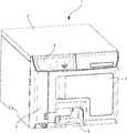
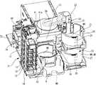
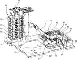
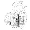
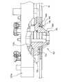
図1はパブリッシャ(メディア処理装置)の外観斜視図、図2はパブリッシャのケースを外した状態の前方側の斜視図、図3はパブリッシャのケースを外した状態の後方側の斜視図、図4はパブリッシャに設置されたレーベルプリンタ部分の斜視図である。Embodiments of a media transport mechanism, a media processing apparatusincluding the media transport mechanism, and a media transport method according to the present invention will be described below with reference to the drawings.
In the present embodiment, a case where the present invention is applied to a media processing apparatus including a publisher will be described as an example.
1 is an external perspective view of the publisher (media processing apparatus), FIG. 2 is a front perspective view of the publisher with the case removed, and FIG. 3 is a rear perspective view of the publisher with the case removed. FIG. 3 is a perspective view of a label printer portion installed in a publisher.
パブリッシャ1は、例えばCDあるいはDVD等の円板状のメディアへのデータの書き込みやメディアのレーベル面への印刷を行うメディア処理装置であり、ほぼ直方体形状のケース2を備えている。このケース2の前面には、左右に開閉可能な開閉扉3,4が取り付けられている。ケース2の上側左端部には、表示ランプ、操作ボタンなどが配列された操作面5が設けられており、また、ケース2の下端には、メディア排出口6が設けられている。 The
正面視右側の開閉扉3は、未使用のブランクメディアMAをセットする時、あるいは作成済みメディアMBを取り出すときに開閉する扉である。
また、正面視左側の開閉扉4は、レーベルプリンタ11のインクカートリッジ12の入れ換え時に開閉するためのものであり、この開閉扉4を開けると、鉛直方向に配列された複数のカートリッジホルダ13を有するカートリッジ装着部14(図2参照)が露出するようになっている。The open /
The open / close door 4 on the left side when viewed from the front is for opening and closing when the
図2にも示すように、メディア処理装置1のケース2の内部には、データ書き込み処理が行われていない複数枚の未使用のブランクメディアMAをスタック可能なメディア保管部としてのブランクメディアスタッカ21と、作成済みメディアMBが保管されるメディア保管部としての作成済みメディアスタッカ22が同軸状態で上下に配置されている。ブランクメディアスタッカ21及び作成済みメディアスタッカ22は、それぞれ図2に示した所定位置に対して着脱自在である。 As shown in FIG. 2, a
ブランクメディアスタッカ21は、左右一対の円弧状の枠板24,25を備えており、これにより、ブランクメディアMAを上側から受け入れ、同軸に積層した状態で収納可能な構成をなしている。ブランクメディアスタッカ21にブランクメディアMAを収納あるいは補充する作業は、開閉扉3を開けてスタッカを取り出すことにより、簡単に行うことが可能となっている。 The
下側の作成済みメディアスタッカ22も同一構造となっており、左右一対の円弧状の枠板27,28を備えており、これによって、作成済みメディアMBを上側から受け入れ、同軸に積層した状態で収納可能なスタッカが構成されている。 The created
また、開閉扉3からは、作成済みメデイアMB(すなわち、データの書き込み、及びレーベル面印刷が終了したメディア)を取り出すこともできる。 Further, the created media MB (that is, the medium on which data writing and label surface printing have been completed) can be taken out from the open /
これらのブランクメディアスタッカ21及び作成済みメディアスタッカ22の後側には、メディア搬送機構31が配置されている。メディア搬送機構31は、ベース72に取り付けられている水平支持板部34とシャーシ32の天板33との間に垂直に架け渡されている垂直ガイド軸35を有している(図5参照)。この垂直ガイド軸35に搬送アーム36が昇降及び旋回可能な状態で支持されている。搬送アーム36は、駆動モータ37によって垂直ガイド軸35に沿って昇降可能であるとともに、垂直ガイド軸35を中心に左右に旋回可能である。メディア搬送機構31によってメディア排出口6に搬送されてきたメディアは、このメディア排出口6から外部に取り出すことが可能である。 A
上下のスタッカ21,22及びメディア搬送機構31の側方の部位には、上下に積層された2つのメディアドライブ41が配置され、これらメディアドライブ41の下側にレーベルプリンタ11の後述するキャリッジ62(図4参照)が移動可能に配置されている。
メディアドライブ41は、メディアへのデータ書き込み位置とメディアの受け取り受け渡しを行うメディア受け渡し位置との間を移動可能なメディアトレイ41aをそれぞれ有している。Two media drives 41 that are stacked one above the other are disposed on the sides of the upper and
The
また、レーベルプリンタ11は、メディアのレーベル面へのレーベル印刷可能な位置とメディアの受け取り受け渡しを行うメディア受け渡し位置との間を移動可能なメディアトレイ51を有している。 Further, the label printer 11 has a
図2及び図3では、上側のメディアドライブ41のメディアトレイ41aが手前に引き出されてメディア受け渡し位置にある状態及び下側のレーベルプリンタ11のメディアトレイ51が奥側のレーベル印刷可能位置にある状態が示されている。また、レーベルプリンタ11はインクジェットプリンタであり、インク供給機構71として各色(本実施形態ではブラック、シアン、マゼンタ、イエロー、ライトシアン、ライトマゼンタの6色)のインクカートリッジ12が用いられ、これらのインクカートリッジ12がカートリッジ装着部14の各カートリッジホルダ13に前方から装着されている。 2 and 3, the media tray 41a of the
ここで、ブランクメディアスタッカ21の左右一対の枠板24,25の間及び作成済みメディアスタッカ22の左右一対の枠板27,28の間には、メディア搬送機構31の搬送アーム36が昇降可能な隙間が形成されている。また、これら上下のブランクメディアスタッカ21と作成済みメディアスタッカ22との間には、メディア搬送機構31の搬送アーム36が水平に旋回して、作成済みメディアスタッカ22の真上に位置できるように隙間が開いている。さらに、メディアトレイ41aをメディアドライブ41に押し込むと、メディア搬送機構31の搬送アーム36を下降させて、メディア受け渡し位置にあるメディアトレイ51にアクセス可能となっている。したがって、搬送アーム36の昇降及び左右への旋回の組み合わせ動作によって、メディアを各部に搬送することが可能とされている。 Here, between the pair of left and
メディアトレイ51のメディア受け渡し位置の下方には、廃棄用メディアMDを保管するための廃棄用スタッカ52が配置されており、この廃棄用スタッカ52には、例えば30枚程度の廃棄用メディアMDが保管可能とされている。メディアトレイ51が廃棄用スタッカ52の上方のメディア受け渡し位置からデータ書き込み位置へ退避した状態でメディア搬送機構31の搬送アーム36により、廃棄用メディアMDを廃棄用スタッカ52に供給可能となっている。 Below the media delivery position of the
このような構成により、CDあるいはDVDであるメディアは、ブランクメディアスタッカ21、作成済みメディアスタッカ22、廃棄用スタッカ52、メディアドライブ41のメディアトレイ41a及びレーベルプリンタ11のメディアトレイ51間を、メディア搬送機構31の搬送アーム36によって搬送される。 With such a configuration, a medium that is a CD or a DVD is transported between the
レーベルプリンタ11はインク吐出用のノズル(図示省略)を備えたインクジェットヘッド61を有するキャリッジ62を備えており、このキャリッジ62は、キャリッジモータの駆動力でキャリッジガイド軸に沿って水平方向に往復移動する(図示省略)。 The label printer 11 includes a
レーベルプリンタ11は、インクカートリッジ12が装着されるカートリッジ装着部14を有するインク供給機構71を備えている。このインク供給機構71は、縦型構造を有しており、パブリッシャ1のベース72上に立設されて鉛直方向に配設されている。このインク供給機構71には、可撓性を有するインク供給チューブ73の一端が接続されており、このインク供給チューブ73の他端は、キャリッジ62に接続されている。 The label printer 11 includes an
そして、インク供給機構71に装着されるインクカートリッジ12のインクは、インク供給チューブ73を介してキャリッジ62に供給され、このキャリッジ62に設けられたダンパユニット及び背圧調整ユニット(図示省略)を経てインクジェットヘッド61に供給されインクノズル(図示省略)から吐出される。
なお、インク供給機構71には、その上部に主部を配置するように加圧機構74が設けられており、この加圧機構74は、圧縮空気を送り出してインクカートリッジ12内を加圧し、インクカートリッジ12内のインクパックに貯留しているインクを送り出す。The ink of the
The
また、キャリッジ62のホームポジション(図4に示す位置)における下方側には、ヘッドメンテナンス機構81が設けられている。
このヘッドメンテナンス機構81は、ホームポジションに配置されたキャリッジ62の下面に露出するインクジェットヘッド61のインクノズルを覆うヘッドキャップ82と、インクジェットヘッド61のヘッドクリーニング動作やインク充填動作によってヘッドキャップ82に排出されたインクを吸引する廃インク吸引ポンプ83とを備えている。A
The
そして、このヘッドメンテナンス機構81の廃インク吸引ポンプ83によって吸引されたインクは、チューブ84を介して、廃インク吸収タンク85へ送り込まれる。
この廃インク吸収タンク85は、ケース86内に吸収材を配設したもので、その上面は、複数の通気孔87を有するカバー88によって覆われている。
なお、ヘッドメンテナンス機構81の下方には、廃インク吸収タンク85の一部である廃インク受け部89が設けられ、ヘッドメンテナンス機構81から滴下したインクを受け止め、吸収材によって吸収するようになっている。The ink sucked by the waste
The waste
Below the
(メディア搬送機構)
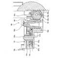
図5はメディア搬送機構を示す斜視図、図6はメディア搬送機構の一部の斜視図、図7は搬送アームとタイミングベルトとの連結機構部分を示す斜視図である。
図5に示すように、メディア搬送機構31は、垂直に取り付けられているシャーシ32を備え、ベース72に取り付けられている水平支持板部34とシャーシ32の天板33との間に、垂直ガイド軸35が取り付けられている。そして、この垂直ガイド軸35に搬送アーム36が昇降可能かつ旋回可能な状態で支持されている。(Media transport mechanism)
FIG. 5 is a perspective view showing the media transport mechanism, FIG. 6 is a perspective view of a part of the media transport mechanism, and FIG. 7 is a perspective view showing a connecting mechanism portion between the transport arm and the timing belt.
As shown in FIG. 5, the
図6に示すように、搬送アーム36の昇降機構は、駆動源である昇降用の駆動モータ37を備えており、この駆動モータ37の回転が、この駆動モータ37の出力軸に取り付けたピニオン97及び伝達歯車98を介して駆動側プーリ101に伝達されるようになっている。駆動側プーリ101は、シャーシ32の上端近傍位置において、水平な回転軸を中心として回転自在に支持されている。シャーシ32の下端近傍位置には、同じく水平な回転軸を中心として回転自在で従動側プーリ103が支持されており、これら駆動側プーリ101及び従動側プーリ103の間にタイミングベルト104が架け渡されている。このタイミングベルト104の左右のベルト部分の一方には、図7に示すように、ベルトクリップ112によって搬送アーム36の基部110が連結されている。
したがって、駆動モータ37を駆動すると、タイミングベルト104が上下方向に移動し、そこに取り付けられている搬送アーム36が垂直ガイド軸35に沿って昇降する。As shown in FIG. 6, the lifting mechanism of the
Therefore, when the
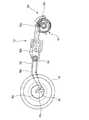
図5に示すように、搬送アーム36の旋回機構は、駆動源である旋回用の駆動モータ105を備えており、この駆動モータ105の出力軸にはピニオン(図示省略)が取り付けられており、このピニオンの回転が、伝達歯車107を備えた減速歯車列を介して、扇形の最終段歯車109に伝達されるようになっている。扇形の最終段歯車109は、垂直ガイド軸35を中心として左右に旋回可能である。また、この最終段歯車109には、搬送アーム36の昇降機構の構成部品が組み付けられているシャーシ32が搭載されている。駆動モータ105を駆動すると、扇形の最終段歯車109が左右に旋回するので、ここに搭載されているシャーシ32が一体となって垂直ガイド軸35を中心として左右に旋回する。この結果、シャーシ32に搭載されている昇降機構によって保持されている搬送アーム36が垂直ガイド軸35を中心として左右に旋回する。 As shown in FIG. 5, the turning mechanism of the
次に、搬送アーム36の支持構造について説明する。
図8は図7に示した構成をその下方側から視た拡大斜視図である。
図7及び図8に示すように、搬送アーム36の基部110には、摺動軸111が鉛直方向に沿って設けられており、この摺動軸111は、タイミングベルト104(図7参照)を把持するベルトクリップ112の軸穴112aに摺動可能に挿通されている。これにより、ベルトクリップ112は、摺動軸111に沿って上下方向へ摺動可能である。Next, a support structure for the
FIG. 8 is an enlarged perspective view of the configuration shown in FIG. 7 viewed from below.
As shown in FIGS. 7 and 8, the
ベルトクリップ112には、係止片112bが形成されており、この係止片112bには、コイルばねである第1の引っ張りばね113の一端が接続されている。第1の引っ張りばね113の他端は、搬送アーム36の基部110に形成されて係止片112bの上方に配置された固定片115に接続されており、これにより、ベルトクリップ112は、第1の引っ張りばね113によって上方へ付勢されている。
なお、ベルトクリップ112には、タイミングベルト104を挟んで固定する固定部112cが形成されている。A
The
ベルトクリップ112の下方側には、押圧レバー116が配設されている。この押圧レバー116は、ベルトクリップ112の側方における搬送アーム36の基部110の下面に設けられた支持板部117に形成された挿通穴118に側方から挿通されており、この支持板部117における支持箇所を支点として揺動可能とされている。この押圧レバー116には、その先端部に、第1の引っ張りばね113よりも付勢力の強いコイルばねからなる第2の引っ張りばね119の一端が接続されており、この第2の引っ張りばね119の他端部は、搬送アーム36の基部110に形成されて押圧レバー116の先端部の上方に配置された固定片120に接続されている。これにより、押圧レバー116は、その先端部が第2の引っ張りばね119によって上方へ付勢されている。また、押圧レバー116の先端部近傍における上方側には、基部110に形成された揺動規制片121が設けられており、第2の引っ張りばね119によって上方へ付勢されている押圧レバー116の揺動が所定位置で規制されている。そして、ベルトクリップ112は、揺動規制片121に当接して揺動が規制された押圧レバー116に対して隙間Sを設けた位置に配置されている。 A
上記支持構造では、昇降用の駆動モータ37によってタイミングベルト104が駆動されると(図5参照)、タイミングベルト104に固定されているベルトクリップ112とともに搬送アーム36が一体となって昇降する。ここで、後述するメディアガイド133、またはグリッピング機構(把持機構)130がメディアに当接し、搬送アーム36の下方への負荷が大きくなると、搬送アーム36に対してベルトクリップ112のみが第1の引っ張りばね113の付勢力に抗して下方へ移動する。また、ベルトクリップ112がタイミングベルト104により更に下方へ移動すると、ベルトクリップ112が押圧レバー116に当接し、その後、搬送アーム36が多少撓んだ後、押圧レバー116が第2の引っ張りばね119の付勢力に抗して支持板部117における支持箇所を支点として揺動する。 In the above support structure, when the
(搬送アームの内部機構)
次に、搬送アーム36の内部機構について説明する。
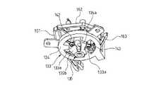
図9は、搬送アームの内部構造を示す斜視図、図10はメディアを把持した搬送アームの下面側から視た平面図、図11は搬送アームの把持部における断面図、図12は搬送アームの把持部に設けられたメディアガイドの斜視図、図13は搬送アームの把持部に設けられたメディアガイドの平面図、図14はグリッピング機構を説明するアームベースの平面図、図15はグリッピング機構の把持爪部分の斜視図、図16はグリッピング機構の拡大平面図、図17から図19は旋回板及び把持爪の動きを説明するそれぞれ平面図、図20は把持爪を説明する把持爪の断面図、図21は蹴落とし機構を示すアームベースの平面図、図22は把持部を断面視した搬送アームの正面図、図23は蹴落とし機構の斜視図、図24は蹴落とし機構に設けられた揺動機構部分の断面図、図25は蹴落とし機構に設けられた揺動機構部分の平面図、図26及び図27は蹴落とし機構の動きを説明するそれぞれ概略平面図である。(Internal mechanism of transfer arm)
Next, the internal mechanism of the
9 is a perspective view showing the internal structure of the transport arm, FIG. 10 is a plan view seen from the lower surface side of the transport arm that grips the media, FIG. 11 is a sectional view of the grip portion of the transport arm, and FIG. FIG. 13 is a plan view of the media guide provided in the gripping portion of the transfer arm, FIG. 14 is a plan view of the arm base for explaining the gripping mechanism, and FIG. 15 is a plan view of the gripping mechanism. FIG. 16 is an enlarged plan view of the gripping mechanism, FIGS. 17 to 19 are plan views for explaining the movement of the swivel plate and the gripping claws, and FIG. 20 is a sectional view of the gripping claws for explaining the gripping claws. FIG. 21 is a plan view of the arm base showing the kick-off mechanism, FIG. 22 is a front view of the transfer arm in a sectional view of the gripping part, FIG. 23 is a perspective view of the kick-off mechanism, and FIG. Sectional view of the rocking mechanism portion has, FIG 25 is a plan view, FIGS. 26 and 27 views, respectively schematic plan explaining movement of kick down mechanism of the rocking mechanism portion provided on the kick down mechanism.
図9に示すように、搬送アーム36は、平面視矩形状の細長いアームベース125aと、このアームベース125aの上に被せた同一輪郭形状のアームケース125bとを備えている。また、アームベース125aにはメディアMを把持するためのグリッピング機構130、蹴落とし機構131及びメディア検出機構200が組み込まれており、これらグリッピング機構130、蹴落とし機構131及びメディア検出機構200がアームケース125bによって覆い隠されている。 As shown in FIG. 9, the
図10及び図11に示すように、アームベース125aの先端近傍における下面部分は、メディアMを把持する把持部132であって、この把持部132には、メディアガイド133が設けられている。 As shown in FIGS. 10 and 11, the lower surface portion in the vicinity of the tip of the
図12及び図13にも示すように、このメディアガイド133は、その中心が、メディアMのピックアップ中心と一致されたもので、アームベース125aの下面側に固定される固定板部134の中心に、下方へ突出するガイド部135を有している。このガイド部135は、メディアMの中心孔Maよりも僅かに小径に形成された円筒状の基端部135aと、この基端部135aから下方へ向かって次第に窄まる円錐形状に形成されたガイド面部135bとを有している。そして、このメディアガイド133は、メディアMに対して近接することにより、メディアMの中心孔Maに挿入され、メディアMの中心孔Maの内周面Mbがガイド面部135bに接触すると、メディアMの中心位置がガイド面部135bによってメディアガイド133の中心位置に調心され、メディアMの中心孔Maが基端部135aに案内されて、メディアMの中心孔Maに基端部135aが挿通される。 As shown in FIGS. 12 and 13, the center of the media guide 133 coincides with the pickup center of the medium M, and the center of the fixed
なお、このメディアガイド133には、3つの窓部133aが形成されており、これら窓部133a内の空間で、グリッピング機構130の後述する3本の把持爪141〜143及び蹴落とし機構131のキックレバー182の作用片183が出没可能である。 The media guide 133 is formed with three
グリッピング機構130は、図12及び図13に示すように、同一円上において等角度(120°)間隔で配置された3本の円柱状の把持爪141〜143を備えており、これらの把持爪141〜143は、アームベース125aの先端部に形成された円形穴125cから下方に垂直に突出され、それぞれメディアガイド133の窓部133aの内側に配置されている。これら3本の把持爪141〜143は、メディアガイド133によって基端部135aに案内されたメディアMの中心孔Maに挿入し、半径方向外方に押し広がり、メディアガイド133の窓部133aから突出することにより、メディアMの中心孔Maの内周面Mbに当接してメディアMを把持する。 As shown in FIGS. 12 and 13, the
各把持爪141〜143は、これらより大径の支持ピン151〜153の下端に取り付けられている。各支持ピン151〜153は、アームベース125aの円形穴125cを貫通してその上側に延び、アームベース125aの上面に配置されている3枚の旋回板161〜163にそれぞれ固定されている。アームベース125aには、その円形穴125cを取り囲む状態で同一円上に等角度間隔で旋回中心軸171〜173が垂直に固定されており、各旋回板161〜163は、これらの旋回中心軸171〜173を中心として旋回可能な状態で支持されている。 The gripping
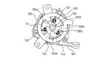
図14から図16に示すように、各旋回板161〜163は、アームベース125aに沿って、その円形穴125cのほぼ円周方向に沿って前方(上面視反時計回り方向)側に延びる前方腕部161a〜163aと、円形穴125cのほぼ円周方向に沿って後方(上面視時計回り方向)側に延びる後方腕部161b〜163bと、旋回中心から円形穴125cの内側に突出している支持腕161c〜163cとを備えている。支持腕161c〜163cの先端部の裏面に、それぞれ支持ピン151〜153が垂直に固定されている。 As shown in FIGS. 14 to 16, each of the swiveling
旋回板161の後方腕部161bには、円形穴125cの略径方向に沿う長孔161dが形成されており、この長孔161dには、旋回板163の前方腕部163aの後端で下方へ突設されたスライドピン163fがスライド可能に挿通されている。
また、旋回板163の後方腕部163bの先端には、円形穴125cの略径方向に沿うスライド面163eが形成されており、このスライド面163eには、旋回板162の前方腕部162aの前端部が接触しないように設定されている。また、旋回板162の後方腕部162bの先端には、円形穴125cの略径方向に沿うスライド面162eが形成されており、このスライド面162eには、旋回板161の前方腕部161aの前端部が摺接可能とされている。ここで、旋回板161の長穴161d及び旋回板162,163のスライド面162e,163eは、各旋回板161〜163が同一方向に旋回するように設定された凹状の湾曲形状に形成されている。A
Further, a
旋回板161の後方腕部161bと旋回板162の後方腕部162bとの間、旋回板162の後方腕部162bと旋回板163の後方腕部163bとの間及び旋回板163の後方腕部163bと旋回板161の後方腕部161bとの間には、それぞれ引っ張りコイルばね(付勢部材)174が架け渡されている。そして、これら引っ張りコイルばね174の引っ張り力によって、旋回板161〜163はガタ付くことなく保持されると共に、各旋回板161〜163に対して図16において矢印R1で示す方向(把持爪141〜143を広げる方向)の付勢力が加わっている。 Between the
図16の状態では、各旋回板161〜163の支持腕161c〜163cの先端に取り付けられている把持爪141〜143の外接円は、メディアMの中心孔Maの内径より大きな径となっている。この状態において、一枚の旋回板161を矢印R2で示す方向に旋回すると、これに連動して、他の二枚の旋回板162,163も同一方向に旋回する。この結果、旋回板161〜163の支持腕161c〜163cが円形穴125cの中心に向けて移動し、これらの先端部に取り付けられている把持爪141〜143がメディアMの中心孔Maに挿入可能な状態まで狭められる。
この状態で把持爪141〜143をメディアMの中心孔Maに挿入し、しかる後に、旋回板161〜163を逆方向R1に旋回すると、把持爪141〜143が半径方向の外側に押し広げられる。この結果、それら把持爪141〜143がメディアMの中心孔Maの内周面Mbに押し付けられ、メディアMが把持された状態になる。In the state of FIG. 16, the circumscribed circle of the gripping
In this state, when the gripping
図14に示すように、旋回板161には、支持腕161cとは反対側から延在する操作腕161gが形成されている。この操作腕161gの先端部には、リンク175の一方の腕部175aの先端が回転自在の状態で連結されている。リンク175は、その中間部を中心としてアームベース125aに回動可能に支持されており、反対側の腕部175bの先端部は電磁ソレノイド176の作動ロッド176aに連結されている。電磁ソレノイド176は、オフ状態において、その作動ロッド176aが内蔵のばねのばね力によって突出状態とされる。 As shown in FIG. 14, the turning
この状態で電磁ソレノイド176をオンに切り替えると、作動ロッド176aが、内蔵ばね力に逆らって引き込まれ、リンク175が旋回し、旋回板161がR2方向に旋回する。すると、図17に示すように、旋回板162の後方腕部162bのスライド面162eが旋回板161の前方腕部161aの先端に摺接するとともに、旋回板161の後方腕部161bの長穴161dの内面が旋回板163の前方腕部163aのスライドピン163fに摺接する。これにより、旋回板162のスライド面162eが旋回板161の前方腕部161aの先端に摺接して円形穴125cの径方向外方へスライドすることにより旋回板162がR2方向に旋回し、また、旋回板163の前方腕部163aのスライドピン163fに旋回板161の後方腕部161bの長穴161dの内面が摺接して旋回板163の前方腕部163aが円形穴125cの中心方向へスライドすることにより旋回板163もR2方向に旋回する。 When the
このように、旋回板161がR2方向に旋回すると、この旋回板161のR2方向への旋回力が他の旋回板162,163に伝達され、図18に示すように、旋回板162,163もR2方向に旋回し、旋回板161〜163の支持腕161c〜163cに設けられた把持爪141〜143がメディアMの中心孔Maよりも十分に小さな外接円内に配置され、メディアMの中心孔Maに挿入可能な状態まで狭められる。 Thus, when the turning
この状態で、電磁ソレノイド176をオフに切り替えると、作動ロッド176aが内蔵のばねのばね力によって突出され、リンク175が旋回する。すると、リンク175の旋回運動が旋回板161に伝わり、この旋回板161がR1方向に旋回する。これに連動して他の二枚の旋回板162,163は、引っ張りコイルばね174の引っ張り力によって、それぞれの後方腕部162b,163bが円形穴125cの中心方向へ引っ張られ、これにより、これら旋回板162,163も旋回板161と同様にR1方向に旋回する。この結果、図19に示すように、把持爪141〜143が押し広げられ、把持爪141〜143がメディアMの中心孔Maの内周面Mbに押し付けられ、メディアMが把持された状態になる。 In this state, when the
このとき、旋回板161に対して旋回板162,163は、引っ張りコイルばね174の引っ張り力によってR1方向に独立して旋回されるので、各把持爪141〜143も、それぞれ独立して半径方向外方へ移動してメディアMの中心孔Maの内周面Mbへ押し付けられることとなる。 At this time, the swiveling
図20に示すように、3本の把持爪141〜143は、支持ピン151〜153の下端から突出した円柱状のピン141a〜143aと、このピン141a〜143aを同心状態で取り囲んでいるゴムなどからなる弾性円筒141b〜143bとを備えている。そして、これら3本の把持爪141〜143は、下方への突出長さlの寸法が、把持するメディアMの厚さt1の寸法以下とされている。この突出長さlは、メディアMの中心孔Maの内周面Mbの厚さt2以上で環状突起部Mcの高さを含んだメディアMの厚さt1以下が望ましい。、これにより、厚さ方向に積層状態のメディアMを把持する際に、把持爪141〜143が2枚目のメディアMの内周面Mbに接触することなく、最上部である1枚目のメディアMだけを把持するようになっている。 As shown in FIG. 20, the three
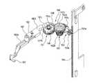
図21から図23に示すように、搬送アーム36のアームベース125aに設けられた蹴落とし機構131は、中間部が連結点181でアームベース125aに回動可能に支持されたキックレバー182を備えている。このキックレバー182は、連結点181を境に、先端側が先端レバー部182a、後端側が後端レバー部182bとされている。先端レバー部182aには、先端で下方に屈曲され、さらに側方にL字状に屈曲された作用片183を有しており、この作用片183が、把持部132のメディアガイド133内に配置されている。 As shown in FIGS. 21 to 23, the kick-
このキックレバー182の作用片183は、把持部132の把持爪141〜143がメディアMを把持した状態で、そのメディアMの下方側で水平に配置されている。具体的には、厚さ方向に積層状態のメディアMの2枚目のメディアMの位置に配置されている。
そして、このキックレバー182は、その連結点181で図21中R3方向へ揺動すると、作用片183がメディアガイド133の窓部133aから側方へ突出し、把持爪141〜143で把持する最上部のメディアMの下方側の2枚目のメディアMの中心孔Maの内周面Mbに当接する。また、この状態からキックレバー182が逆のR4方向へ揺動すると、作用片183がメディアガイド133内に引き込まれる。The
When the
キックレバー182の後端レバー部182bには、揺動機構190が設けられている。この揺動機構190は、複合クラッチ歯車191、鉛直複合伝達歯車192、水平複合伝達歯車193及びラック194を備えている。
ラック194は、図5に示すように、メディア搬送機構31を構成するシャーシ32に、垂直ガイド軸35と平行に垂直に支持されている。このラック194には、水平方向の軸193aを中心として回転可能にアームベース125aに支持された水平複合伝達歯車193のピニオン193bが噛み合わされており、搬送アーム36が昇降されることにより、ラック194に噛み合わされたピニオン193bを有する水平複合伝達歯車193が回転する。A
As shown in FIG. 5, the
水平複合伝達歯車193には、ねじ歯車193cが設けられており、このねじ歯車193cは、鉛直方向の軸192aを中心として回転可能にアームベース125aに支持された鉛直複合伝達歯車192のねじ歯車192bに噛み合わされている。これにより、水平複合伝達歯車193が回転されると、互いに噛み合わされたねじ歯車192b,193cによって水平の軸193aを有する水平複合伝達歯車193の回転が鉛直の軸192aを有する鉛直複合伝達歯車192に伝達され、この鉛直複合伝達歯車192が回転する。
鉛直複合伝達歯車192には、平歯車192cが設けられており、この平歯車192cは、鉛直方向の軸191aを中心として回動可能にアームベース125aに支持された複合クラッチ歯車191の平歯車191bに噛み合わされている。これにより、鉛直複合伝達歯車192が回転されると、互いに噛み合わされた平歯車191b,192cによって鉛直複合伝達歯車192の回転が複合クラッチ歯車191に伝達され、この複合クラッチ歯車191が回転する。The horizontal
The vertical
図24及び図25に示すように、複合クラッチ歯車191は、平歯車191bに対して相対的に回転可能とされた間欠歯車191cを備えている。また、この平歯車191bと間欠歯車191cとの間には、クラッチ機構195が設けられている。平歯車191bは、軸191aが挿通された円筒軸191dを有しており、この円筒軸191dは、間欠歯車191cに形成された円筒軸191eに挿通されている。
図25に示すように、間欠歯車191cは、周面の一部に複数の歯196aからなる歯列196を有しており、この歯列196は、鉛直複合伝達歯車192の平歯車192cと歯合可能とされている。As shown in FIGS. 24 and 25, the composite
As shown in FIG. 25, the
複合クラッチ歯車191に設けられたクラッチ機構195は、間欠歯車191cの円筒軸191eの周囲に巻回されたねじりコイルばね197を有している。平歯車191bが鉛直複合伝達歯車192の平歯車192cによって、図25において上面視反時計回りのR5方向へ回転されると、このねじりコイルばね197により発生する摩擦力によって、間欠歯車191cを平歯車191bと供回りさせる。これにより、間欠歯車191cは、歯列196が鉛直複合伝達歯車192の平歯車192cに歯合し、平歯車191bとともにR5方向へ回転される。これとは逆に、平歯車191bが鉛直複合伝達歯車192の平歯車192cによって、図25において上面視時計回りのR6方向へ回転されると、ねじりコイルばね197により発生する摩擦力によって、間欠歯車191cを平歯車191bと供回りさせる。これにより、間欠歯車191cは、歯列196が鉛直複合伝達歯車192の平歯車192cに歯合し、平歯車191bとともにR6方向へ回転される。 The
また、この間欠歯車191cには、カム穴198が形成されており、このカム穴198には、キックレバー182の後端レバー部182bの後端近傍で下方へ突出するカムピン182cが摺動可能に配置されている。カム穴198は、上面視時計回りに向かって中心側から外周側に変化する経路を有している。これにより、図26に示す状態で、間欠歯車191cが上面視反時計回りのR5方向へ回転すると、カム穴198内のカムピン182cが外周側へ変位し、これにより、図27に示すように、キックレバー182が連結点181を中心としてR3方向へ揺動し、作用片183がメディアガイド133の外方へ突出される。また、この状態で、間欠歯車191cが上面視時計回りのR6方向へ回転すると、カム穴198内のカムピン182cが内周側へ変位し、これにより、図26に示すように、キックレバー182が連結点181を中心としてR4方向へ揺動し、作用片183がメディアガイド133の内方へ引き込まれる。 The
このような構成により、蹴落とし機構131は、搬送アーム36が上昇を開始すると複合クラッチ歯車191がR5方向に回転し始め、さらに搬送アーム36が上昇して複合クラッチ歯車191が図26の状態から図27の状態へ所定量(45°程度)回転する間に、キックレバー182がR3(図22参照)方向へ揺動し、キックレバー182の作用片183が2枚目のメディアMを蹴落とすようになっている。そして、搬送アーム36が下降するときには、複合クラッチ歯車191がR6方向に回転して、それによりキックレバー182がR4(図21参照)方向へ揺動し、作用片183が図26に示すようにメディアガイド133内に引き込まれる。その状態でさらに搬送アーム36が下降しても、複合クラッチ歯車191の間欠歯車191cは、鉛直複合伝達歯車192の平歯車192cによってR6方向へ所定量(45°程度)回転された後は、平歯車192cから歯列196が外れているため、平歯車191bに対して空回りする。 With such a configuration, the kick-
図9に示すように、メディア検出機構200は、後端が揺動可能に支持され、先端が下方へ屈曲されてアームベース125aの下面側へ突出する検出レバー201と、この検出レバー201の側方に設けられた検出器202とを有している。そして、このメディア検出機構200では、搬送アーム36が下降してメディアMの上面が検出レバー201の先端に当接することにより、検出レバー201が上方へ揺動し、この検出レバー201が検出器202の検出領域から外れると、検出器202がオンに切り替わり、この検出器202からの検出信号からメディアMへの近接状態を検出することができる。 As shown in FIG. 9, the
次に、上記構造のメディア搬送機構31による積層されたメディアMのピックアップ動作を説明する。
例えば、ブランクメディアスタッカ21から、積層状態で収納されているメディアMの最上部のメディアMを把持して持ち上げる場合について説明する。
まず、搬送アーム36がブランクメディアスタッカ21の真上の所定高さ位置に配置された状態で、グリッピング機構130の電磁ソレノイド176をオンする。この状態では、電磁ソレノイド176の作動ロッド176aが内蔵されたばねに逆らって引き込まれ、この動きがリンク175を介して旋回板161に伝達され、この旋回板161が図16における矢印R2方向に旋回した配置となる。これにより、残りの旋回板162,163も同一方向に旋回した配置となり、これら3枚の旋回板161〜163の支持腕161c〜163cの先端に取り付けられている把持爪141〜143が相互に接近した位置に移動されて、メディアMの中心孔Maに挿入可能な状態に窄まった状態となる。Next, the pickup operation of the stacked media M by the
For example, a case where the uppermost medium M of the media M stored in a stacked state is grasped and lifted from the
First, the
この後、搬送アーム36の昇降用の駆動モータ37が駆動されて、搬送アーム36の下降動作が開始される。搬送アーム36が下降して最上部のメディアMに接近すると、把持部132のメディアガイド133がメディアMの中心孔Maに挿入される。ここで、ブランクメディアスタッカ21内のメディアMの中心が、把持部132の中心に対してずれていたとしても、メディアMの中心孔Maの内周面Mbが円錐形状のガイド面部135bに接触することにより、メディアMの中心位置がガイド面部135bによってメディアガイド133の中心位置に調心され、メディアMの中心孔Maが基端部135aに案内され、メディアMの中心孔Maに基端部135aが挿通される。つまり、把持するメディアMの中心がピックアップ中心である把持部132の中心に位置決めされる。 Thereafter, the
また、このとき、搬送アーム36に搭載されているメディア検出機構200の検出レバー201の先端がメディアMの表面に当たると、検出レバー201が搬送アーム36の下降に伴って相対的に上方へ揺動し、検出レバー201が検出器202の検出領域から外れ、検出器202がオンに切り替わり、メディアMへの近接状態が検出される。その後、搬送アーム36を予め定めた量だけ下降させて停止させ、搬送アーム36に組み込まれているグリッピング機構130の把持爪141〜143をメディアMの中心孔Maに挿入した状態とする。 At this time, when the tip of the
ところで、メディアMは、ブランクメディアスタッカ21内で積層状態に収容されているが、このように積層されたメディアMは、上下のメディアMと密着していることにより、貼り付き力が生じている場合がある。
したがって、最上部のメディアMに2枚目のメディアMが貼り付いている場合、把持爪141〜143をメディアMの中心孔Maの内周面Mbに当接させただけでは、最上部のメディアMを側方へずらして位置決めするのが困難である。
このため、メディア搬送機構31では、最上部のメディアMに対して上方側から所定の押圧力を作用させることにより、メディアガイド133のガイド面部135bによるメディアMの側方へ向かう押圧力を作用させて、メディアMを確実に側方へ移動させて位置決めするようになっている。By the way, although the media M are accommodated in a stacked state in the
Therefore, when the second medium M is attached to the uppermost medium M, the uppermost medium can be obtained simply by bringing the gripping
For this reason, in the
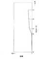
ここで、搬送アーム36のベルトクリップ112の位置とメディアMへの荷重との関係について説明する。
図28は搬送アームのベルトクリップの下降ストロークとメディアにかかる荷重との関係を示すグラフ図である。
まず、搬送アーム36の把持部132が最上部のメディアMに接触した状態(図28におけるAの状態)から駆動モータ37の駆動が継続されると、タイミングベルト104に固定されたベルトクリップ112が弱いばね力の第1の引っ張りばね113の付勢力に抗して下方へ引き下げられ、ベルトクリップ112が隙間Sの寸法分下降し、その後、ベルトクリップ112が押圧レバー116に当接する(図28におけるBの状態)。これにより、最上部のメディアMには、把持部132が接触してからベルトクリップ112が押圧レバー116に当接するまで、弱いばね力の第1の引っ張りばね113の付勢力からなる第1の弾性押圧力が付与される(図28におけるA〜Bの領域)。Here, the relationship between the position of the
FIG. 28 is a graph showing the relationship between the lowering stroke of the belt clip of the transport arm and the load applied to the medium.
First, when the
駆動モータ37の駆動がさらに継続されると、ベルトクリップ112がさらに下降する。このとき、ベルトクリップ112は押圧レバー116に当接していることより、ベルトクリップ112の引き下げ力は、搬送アーム36に伝わることにより、この搬送アーム36が撓み、その撓み力が押圧力として最上部のメディアMに付与される(図28におけるB〜Cの領域)。
駆動モータ37の駆動がさらに継続されてベルトクリップ112が下降されることにより、搬送アーム36の撓み力が強いばね力の第2の引っ張りばね119よりも大きくなると(図28におけるCの状態)、押圧レバー116が第2の引っ張りばね119の付勢力に抗して支持板部117における支持箇所を支点として揺動する。これにより、最上部のメディアMには、第1の引っ張りばね113の付勢力及び搬送アーム36の撓み力に第2の引っ張りばね119の付勢力が加わった第2の弾性押圧力が付与される(図28におけるC〜Eの領域)。When the drive of the
When the driving of the
上記のような荷重の特性を有する上記のメディア搬送機構31では、第1の引っ張りばね113の付勢力及び搬送アーム36の撓み力に第2の引っ張りばね119の付勢力が加わった押圧力がメディアMに付与される領域(図28におけるC〜Eの領域)の適切な位置(例えば、図28におけるDの位置)で駆動モータ37を停止させる。
このようにすると、ブランクメディアスタッカ21内の積層状態のメディアMには、その最上部のメディアMに、適当な荷重(約10N)を付与することができ、これにより、2枚目のメディアMとの貼り付きに関わらず、メディアMをメディアガイド133のガイド面部135bによって確実に側方へ移動させて位置決めすることができる。
また、荷重を付与することにより、メディアMの中心位置がずれていたとしても、メディアガイド133を確実にメディアMの中心孔Maに挿入して位置決めすることができる。In the
In this way, an appropriate load (about 10 N) can be applied to the uppermost medium M to the stacked medium M in the
Moreover, even if the center position of the medium M is shifted by applying a load, the media guide 133 can be reliably inserted into the center hole Ma of the medium M and positioned.
なお、搬送アーム36の剛性を高くし、搬送アーム36のばね定数を大きくすれば、搬送アーム36の撓み力を生じさせる際のベルトクリップ112のストローク(図28におけるB〜Cの領域)を短くして必要な荷重を得ることができる。 If the rigidity of the
また、1枚のメディアMを保持するメディアドライブ41やレーベルプリンタ11のメディアトレイ41a,51からメディアMを持ち上げる場合は、搬送アーム36の把持部132がメディアMに接触してからベルトクリップ112が押圧レバー116に当接するまでの弱いばね力の第1の引っ張りばね113の付勢力からなる第1の弾性押圧力が付与される状態(図28におけるA〜Bの領域)でグリッピング機構130によってメディアMを把持すれば良く、このようにすれば、メディアMの取り出しの際にメディアトレイ41a,51にかかる荷重を極力小さくすることができ、メディアトレイ41a,51への荷重による過負荷の影響を抑えることができる。 When the media M is lifted from the media drive 41 that holds one media M or the
このようにして、ブランクメディアスタッカ21内の最上部のメディアMに所定の第2の弾性押圧力を付与した状態で、メディアMの中心孔Maに挿入された把持爪141〜143を中心孔Maの径方向に押し広げて中心孔Maの内周面Mbに押し付ける。
具体的には、まず、電磁ソレノイド176をオフに切り替え、その作動ロッド176aが、ばねのばね力によって突出すると、作動ロッド176aに、リンク175を介して連結されている旋回板161がR1方向に旋回する。これに連動して他の二枚の旋回板162,163が、引っ張りコイルばね174の引っ張り力によって、旋回板161と同様にR1方向に旋回する。この結果、把持爪141〜143が押し広げられ、把持爪141〜143がメディアMの中心孔Maの内周面Mbに押し付けられ、メディアMが把持された状態になる。In this manner, the gripping
Specifically, first, when the
このとき、旋回板161に対して旋回板162,163は、引っ張りコイルばね174の引っ張り力によってR1方向に独立して旋回されるので、各把持爪141〜143も、それぞれ独立して半径方向外方に移動してメディアMの中心孔Maの内周面Mbへ押し付けられる。
したがって、万一、最上部のメディアMの中心位置がピックアップ中心からずれていたとしても、各把持爪141〜143が、それぞれ独立して外周側へ広がるので、メディアMの中心孔Maの内周面Mbに全ての把持爪141〜143が当接し、把持不良などが確実に防止される。At this time, the swiveling
Accordingly, even if the center position of the uppermost medium M is deviated from the center of the pickup, the gripping
しかも、各把持爪141〜143は、下方への突出長さ寸法が、把持するメディアMの厚さ寸法以下であるため、最上部のメディアMに対して2枚目のメディアMの中心位置がずれていたとしても、把持爪141〜143が2枚目のメディアMの中心孔Maの縁部などに接触して把持不良を生じるような不具合も防止される。 In addition, since each of the gripping
このようにしてメディアMを把持したら、把持爪141〜143を径方向に押し広げた状態のままで、搬送アーム36を上昇させ、把持したメディアMを持ち上げる。このとき、把持した最上部のメディアMは、全ての把持爪141〜143によって確実に把持されているので、把持不良なく円滑に持ち上げられる。 When the medium M is gripped in this manner, the
また、メディアMを持ち上げるべく、搬送アーム36が上昇すると、蹴落とし機構131のキックレバー182が連結点181を中心として図21中矢印R3方向へ揺動し、作用片183がメディアガイド133の外方へ突出される。
これにより、万一、持ち上げるメディアMに貼り付いて2枚目のメディアMが持ち上げられそうになっても、キックレバー192の作用片183が2枚目のメディアMの中心孔Maの内周面Mbに当接することにより、2枚目のメディアMを確実に蹴落として最上部のメディアMだけを持ち上げることができる。When the
As a result, even if the second medium M is likely to be lifted by sticking to the medium M to be lifted, the
以上説明したように、上記実施形態のメディア搬送機構31によれば、グリッピング機構130によって把持して持ち上げる最上部のメディアMの直下のメディアMを蹴落とす蹴落とし機構131を備えているため、把持対象の1枚のメディアMの直下(2枚目)のメディアMが密着して貼り付いていたとしても、この直下のメディアMを蹴落として、最上部のメディアMだけを、把持不良なく持ち上げて搬送することができる。 As described above, according to the
また、メディアMの中心孔Maから径方向外方へ出没する作用片183を有する揺動可能なキックレバー182を備えているので、最上部のメディアMを把持して持ち上げる際に、キックレバー182を揺動させて作用片183を突出させることにより、把持対象のメディアMに密着して貼り付いていた直下のメディアMを容易に蹴落とすことができる。
しかも、搬送アーム36の昇降によってキックレバー182を揺動させる揺動機構190を備えているので、専用の駆動機構を設けることなく、キックレバー182を揺動させて把持対象のメディアMの直下のメディアMを蹴落とすことができる。Further, since the
In addition, since the
また、揺動機構190が、鉛直方向に配置されたラック194と、このラック194に歯合したピニオン193bとを有し、搬送アーム36の昇降運動によって回転されるピニオン193bの回転力によってキックレバー182を揺動させるので、搬送アーム36を昇降させることにより、容易にキックレバー182を揺動させて作用片183を径方向外方へ出没させることができる。 Further, the
さらには、揺動機構190が、搬送アーム36の昇降時に所定角度だけ回転可能な複合クラッチ歯車191を備えるので、搬送アーム36を上昇させて把持対象のメディアMを持ち上げるときは、搬送アーム36の上昇の際に所定角度だけ回転した複合クラッチ歯車191によってキックレバー182が所定量だけ揺動され、これにより、作用片183を径方向外方に所定量だけ突出させて把持対象の直下のメディアMを蹴落とすことができる。 Furthermore, since the
また、メディアMを把持するため、あるいは把持したメディアMを所定位置に載置させるために搬送アーム36を下降させるときは、搬送アーム36の下降の際に所定角度だけ逆回転した複合クラッチ歯車191によってキックレバー182が所定量だけ逆方向へ揺動され、これにより、作用片183を引き込むことができ、把持対象のメディアMや載置するメディアMへの作用片183の干渉を防止することができる。 Further, when the
そして、上記パブリッシャ1によれば、メディアスタッカ21,22内で積層状態に収容されたメディアMを確実に把持することが可能なメディア搬送機構31を備えているので、処理対象の所定のメディアMを確実に搬送することができ、処理の信頼性の高い処理装置とすることができる。 The
1…パブリッシャ(メディア処理装置)、31…メディア搬送機構、36…搬送アーム、130…グリッピング機構(把持機構)、131…蹴落とし機構、182…キックレバー、183…作用片、190…揺動機構、191…複合クラッチ歯車(クラッチ歯車)、193b…ピニオン、194…ラック、M…メディア、Ma…中心孔。 DESCRIPTION OF
Claims (8)
Translated fromJapanese前記搬送アームは、前記把持機構によって把持された最上部のメディアの直下のメディアに当接して前記直下のメディアを前記最上部のメディアに対して移動させる作用片を有する移動可能なレバーを備えていることを特徴とするメディア搬送機構。A media transport mechanism in which a movable transport arm is provided with a gripping mechanism for gripping the uppermost medium of the stacked media,
The transport arm is provided with a movable lever having a working pieceto move the media directly under said contactthe media just below the uppermost mediumthat has been gripped by the gripping mechanismrelative to the uppermost medium A media transport mechanism characterized by that.
前記作用片は、前記レバーの移動により、前記把持機構によって把持するメディアの下方側で、前記メディアの中心孔から径方向外方へ移動することを特徴とするメディア搬送機構。The media transport mechanism according to claim 1,
It saidworking piece,by movement of the lever, in the lower side of the media for gripping by the gripping mechanism, the media transportation mechanism, wherein thebenzalkoniummove from the center hole of the medium radially outward.
前記レバーは、前記搬送アームの移動によって移動されることを特徴とするメディア搬送機構。The media transport mechanism according to claim 2,
The media transport mechanism, wherein thelever ismoved bymovement of the transport arm.
前記レバーは、前記搬送アームの上昇時には前記作用片が最上部のメディアの直下のメディアに当接して径方向に移動させる位置となり、前記搬送アームの下降時には前記作用片が最上部のメディアの直下のメディアに当接しない位置となるように移動されることを特徴とするメディア搬送機構。 When the transport arm is lifted, the lever comes into contact with the medium immediately below the uppermost medium to move in the radial direction. When the transport arm is lowered, the lever is moved directly below the uppermost medium. A media transport mechanism that is moved so as to be in a position that does not contact the media.
前記レバーを移動させる機構は、鉛直方向に配置されたラックと、このラックに歯合したピニオンとを有し、前記搬送アームの移動によって回転されるピニオンの回転力によって前記レバーを移動させることを特徴とするメディア搬送機構。 The mechanism for moving the lever includes a rack arranged in a vertical direction and a pinion meshed with the rack, and moves the lever by the rotational force of the pinion rotated by the movement of the transfer arm. Features a media transport mechanism.
前記レバーを移動させる機構は、前記搬送アームの移動時に所定角度だけ回転可能なクラッチ歯車を備えていることを特徴とするメディア搬送機構。 The mechanism for moving the lever includes a clutch gear that is rotatable by a predetermined angle when the transport arm is moved.
前記把持機構により積層状態のメディアの最上部のメディアを把持した状態で、前記搬送アームを移動させ、その移動中に前記レバーを移動させて、把持した前記最上部のメディアの直下のメディアに前記作用片を当接させることを特徴とするメディア搬送方法。A movable transfer arm, gripping mechanism for gripping the uppermost medium of the media in a stacked state is provided, wherein the transport arm isto contact the media just below the uppermost mediumthat has been gripped by the gripping mechanism A media transport method by a media transport mechanism including a movable lever havingan action piecefor moving the media directly below the top media ,
With the gripping mechanism gripping the uppermost medium of the stacked media, the transport arm is moved, the lever is moved during the movement, and the medium immediately below the gripped uppermost medium is moved to the media. A media conveying method, comprising: contacting an action piece.
Priority Applications (9)
| Application Number | Priority Date | Filing Date | Title |
|---|---|---|---|
| JP2007099879AJP4375425B2 (en) | 2007-04-05 | 2007-04-05 | Media transport mechanism, media processing apparatus including the same, and media transport method |
| US12/080,301US8438584B2 (en) | 2007-04-05 | 2008-04-02 | Medium transporting unit and media processing apparatus for reading or writing data |
| EP10171492.1AEP2249342B1 (en) | 2007-04-05 | 2008-04-03 | Disk transporting unit and disk processing apparatus |
| EP08006770.5AEP1978518B1 (en) | 2007-04-05 | 2008-04-03 | Disk transporting unit, disk processing apparatus and method |
| CN2008100911729ACN101281761B (en) | 2007-04-05 | 2008-04-07 | Medium conveying unit and medium processing device provided with the medium conveying unit |
| CN201110093893.5ACN102243883B (en) | 2007-04-05 | 2008-04-07 | Medium transporting unit and medium processing apparatus |
| CN201110093896.9ACN102208198B (en) | 2007-04-05 | 2008-04-07 | Medium transporting unit, medium processing apparatus and medium transporting method |
| US13/860,277US8789075B2 (en) | 2007-04-05 | 2013-04-10 | Medium transporting unit and medium processing apparatus |
| US14/306,840US9449639B2 (en) | 2007-04-05 | 2014-06-17 | Medium transporting unit and medium processing apparatus |
Applications Claiming Priority (1)
| Application Number | Priority Date | Filing Date | Title |
|---|---|---|---|
| JP2007099879AJP4375425B2 (en) | 2007-04-05 | 2007-04-05 | Media transport mechanism, media processing apparatus including the same, and media transport method |
Related Child Applications (1)
| Application Number | Title | Priority Date | Filing Date |
|---|---|---|---|
| JP2008252582ADivisionJP5146233B2 (en) | 2008-09-30 | 2008-09-30 | Media transport mechanism and media processing apparatus provided with the same |
Publications (3)
| Publication Number | Publication Date |
|---|---|
| JP2008257805A JP2008257805A (en) | 2008-10-23 |
| JP2008257805A5 JP2008257805A5 (en) | 2009-03-26 |
| JP4375425B2true JP4375425B2 (en) | 2009-12-02 |
Family
ID=39524663
Family Applications (1)
| Application Number | Title | Priority Date | Filing Date |
|---|---|---|---|
| JP2007099879AExpired - Fee RelatedJP4375425B2 (en) | 2007-04-05 | 2007-04-05 | Media transport mechanism, media processing apparatus including the same, and media transport method |
Country Status (4)
| Country | Link |
|---|---|
| US (3) | US8438584B2 (en) |
| EP (2) | EP2249342B1 (en) |
| JP (1) | JP4375425B2 (en) |
| CN (3) | CN102243883B (en) |
Families Citing this family (11)
| Publication number | Priority date | Publication date | Assignee | Title |
|---|---|---|---|---|
| JP5001622B2 (en)* | 2006-10-23 | 2012-08-15 | セイコーエプソン株式会社 | Media processing device |
| JP4375425B2 (en) | 2007-04-05 | 2009-12-02 | セイコーエプソン株式会社 | Media transport mechanism, media processing apparatus including the same, and media transport method |
| JP5012541B2 (en)* | 2008-01-31 | 2012-08-29 | セイコーエプソン株式会社 | Media processing device |
| JP2010123184A (en)* | 2008-11-19 | 2010-06-03 | Teac Corp | Disk holding device and disk processing device |
| JP5228874B2 (en)* | 2008-12-17 | 2013-07-03 | セイコーエプソン株式会社 | Media transport mechanism and media processing apparatus |
| JP5347519B2 (en)* | 2009-01-19 | 2013-11-20 | セイコーエプソン株式会社 | Media processing apparatus, control method thereof, and program |
| US8687315B2 (en) | 2011-05-11 | 2014-04-01 | International Business Machines Corporation | Data storage system using a media mobility unit (MMU), the MMU, and methods of use thereof |
| JP5874294B2 (en) | 2011-10-13 | 2016-03-02 | セイコーエプソン株式会社 | Media transport mechanism, control method of media transport mechanism, and media processing apparatus |
| CN111653294B (en)* | 2017-09-25 | 2022-02-01 | 光宝科技股份有限公司 | Disc picking and placing device and operation method thereof |
| CN110165980B (en)* | 2018-02-08 | 2021-07-06 | 马鞍山电力规划勘察设计院有限责任公司 | Adjustable energy-saving power generation device |
| CN112259131B (en)* | 2019-07-22 | 2021-12-10 | 苏州互盟信息存储技术有限公司 | CD burning and printing integrated machine |
Family Cites Families (46)
| Publication number | Priority date | Publication date | Assignee | Title |
|---|---|---|---|---|
| JPH0720492B2 (en) | 1986-03-24 | 1995-03-08 | 東レ株式会社 | Blood purification device |
| JPS62176131U (en) | 1986-04-30 | 1987-11-09 | ||
| JPH0772017B2 (en) | 1986-12-22 | 1995-08-02 | 株式会社日立製作所 | How to separate stacked parts |
| US5291465A (en)* | 1990-05-09 | 1994-03-01 | Dennis James T | Automatic changer for digital discs |
| NL9101846A (en)* | 1991-11-05 | 1993-06-01 | Jong Dirk De | COMPACT DISK PACKER. |
| TW299439B (en)* | 1995-04-11 | 1997-03-01 | Discovision Ass | |
| JP3514549B2 (en)* | 1995-05-26 | 2004-03-31 | アルパイン株式会社 | Transport device for recording media |
| JPH0929506A (en) | 1995-07-11 | 1997-02-04 | Showa Alum Corp | Device for supplying blanks for magnetic disk substrates to lathes |
| DE29518578U1 (en) | 1995-11-23 | 1996-01-18 | Kodak Ag, 70327 Stuttgart | Device for removing plate-shaped objects from a stack |
| US5734629A (en)* | 1995-12-28 | 1998-03-31 | Rimage Corporation | CD transporter |
| EP0836184B1 (en)* | 1996-10-10 | 2004-12-29 | Lg Electronics Inc. | A disc loading and unloading apparatus of an optical disc player |
| US7145841B1 (en)* | 1997-03-13 | 2006-12-05 | David Miller | Programmable self-operating compact disk duplication system |
| US6822932B2 (en)* | 1997-03-13 | 2004-11-23 | David Miller | Programmable self-operating compact disk duplication system |
| JP4032552B2 (en) | 1999-03-23 | 2008-01-16 | ソニー株式会社 | Disc chucking device and disc recording and / or reproducing device |
| JP2000339802A (en)* | 1999-05-27 | 2000-12-08 | Matsushita Electric Ind Co Ltd | Disk holding device |
| JP3946438B2 (en)* | 2000-01-26 | 2007-07-18 | 有限会社データンク | Disc-shaped storage medium supply device |
| US6802070B2 (en)* | 2000-06-09 | 2004-10-05 | Primera Technology, Inc. | Compact disc transporter |
| JP2001351302A (en)* | 2000-06-09 | 2001-12-21 | Sony Corp | Disk recorder and/or reproducer |
| US6848113B2 (en)* | 2001-07-02 | 2005-01-25 | Amtren Corporation | Optical media pick and process |
| JP3852367B2 (en) | 2002-05-14 | 2006-11-29 | ティアック株式会社 | Disk unit |
| JP3889666B2 (en)* | 2002-05-16 | 2007-03-07 | パイオニア株式会社 | Disk drive |
| US20040005213A1 (en)* | 2002-05-22 | 2004-01-08 | Pavel Hegedus | Method and apparatus for firm handling disc shaped objects with a concentric bore |
| US6760052B2 (en)* | 2002-06-03 | 2004-07-06 | Primera Technology, Inc. | CD recorder and printer |
| US20050066343A1 (en)* | 2003-09-05 | 2005-03-24 | Hajime Mizuno | Recording medium transporting apparatus and disc changer apparatus |
| US7254818B2 (en)* | 2004-01-20 | 2007-08-07 | Primera Technology, Inc. | Self aligning disc tray drive |
| US7349294B2 (en)* | 2004-01-20 | 2008-03-25 | Primera Technology Inc. | Disc error checking sensor for printers and duplicators |
| JP4487583B2 (en)* | 2004-02-05 | 2010-06-23 | セイコーエプソン株式会社 | Cam member and recording apparatus including the cam member |
| US7360812B2 (en)* | 2004-03-27 | 2008-04-22 | Anton Vasile Ionescu | Automatic device, equipment and methods for handling objects |
| EP1741043A4 (en)* | 2004-04-01 | 2008-11-05 | Victor Waiman | Unattended data storage system |
| DE102005049843A1 (en) | 2004-10-18 | 2006-04-20 | Adr Ag | Lifting device for disk like CD or DVD, comprising lifting element and holding element |
| JP4839621B2 (en) | 2005-01-19 | 2011-12-21 | ティアック株式会社 | Disk processing unit |
| US7540237B2 (en)* | 2005-01-19 | 2009-06-02 | Kubin Dale K | Printer |
| JP2007099879A (en) | 2005-10-04 | 2007-04-19 | Nippon Synthetic Chem Ind Co Ltd:The | Adhesive and its adhesive sheet |
| US7650612B2 (en)* | 2005-12-22 | 2010-01-19 | Datatronics Technology, Inc. | Transportation arm device for carrying discs |
| JP2007310920A (en)* | 2006-05-16 | 2007-11-29 | Seiko Epson Corp | Disc gripping mechanism |
| US20080092153A1 (en)* | 2006-10-11 | 2008-04-17 | Imation Corp. | System and process for forming a durable image on an optical disk |
| US7940609B2 (en)* | 2007-01-04 | 2011-05-10 | Datatronics Technology, Inc. | System for duplication of data onto disks |
| JP4375425B2 (en) | 2007-04-05 | 2009-12-02 | セイコーエプソン株式会社 | Media transport mechanism, media processing apparatus including the same, and media transport method |
| JP4375426B2 (en)* | 2007-04-05 | 2009-12-02 | セイコーエプソン株式会社 | Media transport mechanism and media processing apparatus provided with the same |
| JP4918888B2 (en)* | 2007-06-19 | 2012-04-18 | セイコーエプソン株式会社 | Media processing apparatus and control method thereof |
| US7885145B2 (en)* | 2007-10-26 | 2011-02-08 | Samsung Electronics Co. Ltd. | System and method for selection of an object of interest during physical browsing by finger pointing and snapping |
| US7835233B2 (en)* | 2008-08-08 | 2010-11-16 | Vinpower, Inc. | Disc autoloader and duplicator having one-dimensional robotic arm movement |
| US8085625B2 (en)* | 2009-05-22 | 2011-12-27 | Vinpower Inc. | Burner system capable of inverting an optical disc and inverter thereof |
| TWM398178U (en)* | 2010-06-15 | 2011-02-11 | Acard Technology Corp | recording device |
| JP5874294B2 (en)* | 2011-10-13 | 2016-03-02 | セイコーエプソン株式会社 | Media transport mechanism, control method of media transport mechanism, and media processing apparatus |
| JP6152977B2 (en)* | 2012-08-09 | 2017-06-28 | パナソニックIpマネジメント株式会社 | Disc cartridge and information recording / reproducing apparatus |
- 2007
- 2007-04-05JPJP2007099879Apatent/JP4375425B2/ennot_activeExpired - Fee Related
- 2008
- 2008-04-02USUS12/080,301patent/US8438584B2/ennot_activeExpired - Fee Related
- 2008-04-03EPEP10171492.1Apatent/EP2249342B1/ennot_activeCeased
- 2008-04-03EPEP08006770.5Apatent/EP1978518B1/ennot_activeCeased
- 2008-04-07CNCN201110093893.5Apatent/CN102243883B/ennot_activeExpired - Fee Related
- 2008-04-07CNCN2008100911729Apatent/CN101281761B/ennot_activeExpired - Fee Related
- 2008-04-07CNCN201110093896.9Apatent/CN102208198B/ennot_activeExpired - Fee Related
- 2013
- 2013-04-10USUS13/860,277patent/US8789075B2/enactiveActive
- 2014
- 2014-06-17USUS14/306,840patent/US9449639B2/ennot_activeExpired - Fee Related
Also Published As
| Publication number | Publication date |
|---|---|
| US8438584B2 (en) | 2013-05-07 |
| US9449639B2 (en) | 2016-09-20 |
| EP1978518B1 (en) | 2013-08-21 |
| CN102208198B (en) | 2014-04-16 |
| EP2249342A2 (en) | 2010-11-10 |
| EP2249342B1 (en) | 2015-06-24 |
| CN102208198A (en) | 2011-10-05 |
| US20080250436A1 (en) | 2008-10-09 |
| US20140348626A1 (en) | 2014-11-27 |
| CN101281761A (en) | 2008-10-08 |
| US20130305265A1 (en) | 2013-11-14 |
| EP1978518A2 (en) | 2008-10-08 |
| EP2249342A3 (en) | 2011-12-14 |
| CN102243883A (en) | 2011-11-16 |
| US8789075B2 (en) | 2014-07-22 |
| JP2008257805A (en) | 2008-10-23 |
| CN102243883B (en) | 2014-11-05 |
| CN101281761B (en) | 2011-06-01 |
| EP1978518A3 (en) | 2009-09-30 |
Similar Documents
| Publication | Publication Date | Title |
|---|---|---|
| JP4375425B2 (en) | Media transport mechanism, media processing apparatus including the same, and media transport method | |
| JP4375426B2 (en) | Media transport mechanism and media processing apparatus provided with the same | |
| JP5056127B2 (en) | Media transport mechanism and media processing apparatus provided with the same | |
| JP4882864B2 (en) | Media transport mechanism and media processing apparatus provided with the same | |
| JP4918888B2 (en) | Media processing apparatus and control method thereof | |
| JP5146233B2 (en) | Media transport mechanism and media processing apparatus provided with the same | |
| JP5532080B2 (en) | Media transport mechanism and media processing apparatus provided with the same | |
| JP5408297B2 (en) | Media transport mechanism and media processing apparatus provided with the same | |
| JP5920425B2 (en) | Media transport mechanism and media processing apparatus provided with the same | |
| JP5018720B2 (en) | Media transport mechanism and media processing apparatus provided with the same | |
| JP5644817B2 (en) | Media transport mechanism and media processing apparatus provided with the same | |
| JP5228874B2 (en) | Media transport mechanism and media processing apparatus | |
| JP2010146684A (en) | Medium conveying mechanism and medium processing device | |
| JP4930221B2 (en) | Control method of media transport mechanism and media processing apparatus | |
| JP2009015928A (en) | Control method of media transport mechanism, media transport mechanism and media processing apparatus | |
| JP2009176377A (en) | Media processing device |
Legal Events
| Date | Code | Title | Description |
|---|---|---|---|
| A521 | Request for written amendment filed | Free format text:JAPANESE INTERMEDIATE CODE: A523 Effective date:20090205 | |
| A621 | Written request for application examination | Free format text:JAPANESE INTERMEDIATE CODE: A621 Effective date:20090205 | |
| A131 | Notification of reasons for refusal | Free format text:JAPANESE INTERMEDIATE CODE: A131 Effective date:20090526 | |
| A521 | Request for written amendment filed | Free format text:JAPANESE INTERMEDIATE CODE: A523 Effective date:20090724 | |
| TRDD | Decision of grant or rejection written | ||
| A01 | Written decision to grant a patent or to grant a registration (utility model) | Free format text:JAPANESE INTERMEDIATE CODE: A01 Effective date:20090818 | |
| A01 | Written decision to grant a patent or to grant a registration (utility model) | Free format text:JAPANESE INTERMEDIATE CODE: A01 | |
| A61 | First payment of annual fees (during grant procedure) | Free format text:JAPANESE INTERMEDIATE CODE: A61 Effective date:20090831 | |
| R150 | Certificate of patent or registration of utility model | Ref document number:4375425 Country of ref document:JP Free format text:JAPANESE INTERMEDIATE CODE: R150 Free format text:JAPANESE INTERMEDIATE CODE: R150 | |
| FPAY | Renewal fee payment (event date is renewal date of database) | Free format text:PAYMENT UNTIL: 20120918 Year of fee payment:3 | |
| FPAY | Renewal fee payment (event date is renewal date of database) | Free format text:PAYMENT UNTIL: 20130918 Year of fee payment:4 | |
| S531 | Written request for registration of change of domicile | Free format text:JAPANESE INTERMEDIATE CODE: R313531 | |
| R350 | Written notification of registration of transfer | Free format text:JAPANESE INTERMEDIATE CODE: R350 | |
| LAPS | Cancellation because of no payment of annual fees |