JP4374246B2 - Improve the throughput of automated laboratory analyzers by sorting analysis according to type - Google Patents
Improve the throughput of automated laboratory analyzers by sorting analysis according to typeDownload PDFInfo
- Publication number
- JP4374246B2 JP4374246B2JP2003517594AJP2003517594AJP4374246B2JP 4374246 B2JP4374246 B2JP 4374246B2JP 2003517594 AJP2003517594 AJP 2003517594AJP 2003517594 AJP2003517594 AJP 2003517594AJP 4374246 B2JP4374246 B2JP 4374246B2
- Authority
- JP
- Japan
- Prior art keywords
- analysis
- cuvette
- time
- group
- sample
- Prior art date
- Legal status (The legal status is an assumption and is not a legal conclusion. Google has not performed a legal analysis and makes no representation as to the accuracy of the status listed.)
- Expired - Fee Related
Links
- 238000004458analytical methodMethods0.000titleclaimsdescription267
- 239000003153chemical reaction reagentSubstances0.000claimsabstractdescription148
- 238000006243chemical reactionMethods0.000claimsabstractdescription99
- 238000000034methodMethods0.000claimsdescription46
- 238000011068loading methodMethods0.000claimsdescription11
- 238000002156mixingMethods0.000claimsdescription7
- 230000003213activating effectEffects0.000claims2
- 238000003556assayMethods0.000abstract5
- 239000000523sampleSubstances0.000description136
- 238000007792additionMethods0.000description47
- 238000012360testing methodMethods0.000description30
- 239000007788liquidSubstances0.000description26
- 238000012545processingMethods0.000description20
- 238000007689inspectionMethods0.000description16
- 230000008569processEffects0.000description10
- 239000000203mixtureSubstances0.000description9
- 239000012491analyteSubstances0.000description8
- 238000005259measurementMethods0.000description8
- 150000002500ionsChemical class0.000description7
- 238000012546transferMethods0.000description7
- 230000009471actionEffects0.000description6
- 238000004140cleaningMethods0.000description5
- 238000011534incubationMethods0.000description5
- QGZKDVFQNNGYKY-UHFFFAOYSA-NAmmoniaChemical compoundNQGZKDVFQNNGYKY-UHFFFAOYSA-N0.000description4
- HVYWMOMLDIMFJA-DPAQBDIFSA-NcholesterolChemical compoundC1C=C2C[C@@H](O)CC[C@]2(C)[C@@H]2[C@@H]1[C@@H]1CC[C@H]([C@H](C)CCCC(C)C)[C@@]1(C)CC2HVYWMOMLDIMFJA-DPAQBDIFSA-N0.000description4
- DDRJAANPRJIHGJ-UHFFFAOYSA-NcreatinineChemical compoundCN1CC(=O)NC1=NDDRJAANPRJIHGJ-UHFFFAOYSA-N0.000description4
- 238000010586diagramMethods0.000description4
- 238000003018immunoassayMethods0.000description4
- 239000011541reaction mixtureSubstances0.000description4
- 230000035484reaction timeEffects0.000description4
- 238000005070samplingMethods0.000description4
- 238000000926separation methodMethods0.000description4
- 108010028780Complement C3Proteins0.000description3
- 102000016918Complement C3Human genes0.000description3
- 239000012472biological sampleSubstances0.000description3
- 230000000694effectsEffects0.000description3
- 230000007613environmental effectEffects0.000description3
- 230000006870functionEffects0.000description3
- 230000006872improvementEffects0.000description3
- 239000013610patient sampleSubstances0.000description3
- 238000005406washingMethods0.000description3
- USSIQXCVUWKGNF-UHFFFAOYSA-N6-(dimethylamino)-4,4-diphenylheptan-3-oneChemical compoundC=1C=CC=CC=1C(CC(C)N(C)C)(C(=O)CC)C1=CC=CC=C1USSIQXCVUWKGNF-UHFFFAOYSA-N0.000description2
- 108010088751AlbuminsProteins0.000description2
- 102000009027AlbuminsHuman genes0.000description2
- 102000021944ButyrylcholinesteraseHuman genes0.000description2
- 108010053652ButyrylcholinesteraseProteins0.000description2
- 108010074051C-Reactive ProteinProteins0.000description2
- 102100032752C-reactive proteinHuman genes0.000description2
- OYPRJOBELJOOCE-UHFFFAOYSA-NCalciumChemical compound[Ca]OYPRJOBELJOOCE-UHFFFAOYSA-N0.000description2
- 102000004420Creatine KinaseHuman genes0.000description2
- 108010042126Creatine kinaseProteins0.000description2
- WDJUZGPOPHTGOT-OAXVISGBSA-NDigitoxinNatural productsO([C@H]1[C@@H](C)O[C@@H](O[C@@H]2C[C@@H]3[C@@](C)([C@@H]4[C@H]([C@]5(O)[C@@](C)([C@H](C6=CC(=O)OC6)CC5)CC4)CC3)CC2)C[C@H]1O)[C@H]1O[C@@H](C)[C@H](O[C@H]2O[C@@H](C)[C@@H](O)[C@@H](O)C2)[C@@H](O)C1WDJUZGPOPHTGOT-OAXVISGBSA-N0.000description2
- 238000008789Direct BilirubinMethods0.000description2
- 108020004206Gamma-glutamyltransferaseProteins0.000description2
- CEAZRRDELHUEMR-URQXQFDESA-NGentamicinChemical compoundO1[C@H](C(C)NC)CC[C@@H](N)[C@H]1O[C@H]1[C@H](O)[C@@H](O[C@@H]2[C@@H]([C@@H](NC)[C@@](C)(O)CO2)O)[C@H](N)C[C@@H]1NCEAZRRDELHUEMR-URQXQFDESA-N0.000description2
- 229930182566GentamicinNatural products0.000description2
- WQZGKKKJIJFFOK-GASJEMHNSA-NGlucoseNatural productsOC[C@H]1OC(O)[C@H](O)[C@@H](O)[C@@H]1OWQZGKKKJIJFFOK-GASJEMHNSA-N0.000description2
- 102000003855L-lactate dehydrogenaseHuman genes0.000description2
- 108700023483L-lactate dehydrogenasesProteins0.000description2
- CXOFVDLJLONNDW-UHFFFAOYSA-NPhenytoinChemical compoundN1C(=O)NC(=O)C1(C=1C=CC=CC=1)C1=CC=CC=C1CXOFVDLJLONNDW-UHFFFAOYSA-N0.000description2
- OAICVXFJPJFONN-UHFFFAOYSA-NPhosphorusChemical compound[P]OAICVXFJPJFONN-UHFFFAOYSA-N0.000description2
- 102000007584PrealbuminHuman genes0.000description2
- 108010071690PrealbuminProteins0.000description2
- 102100035703Prostatic acid phosphataseHuman genes0.000description2
- 238000008050Total Bilirubin ReagentMethods0.000description2
- 102000004338TransferrinHuman genes0.000description2
- 108090000901TransferrinProteins0.000description2
- PNNCWTXUWKENPE-UHFFFAOYSA-N[N].NC(N)=OChemical compound[N].NC(N)=OPNNCWTXUWKENPE-UHFFFAOYSA-N0.000description2
- 229910021529ammoniaInorganic materials0.000description2
- WQZGKKKJIJFFOK-VFUOTHLCSA-Nbeta-D-glucoseChemical compoundOC[C@H]1O[C@@H](O)[C@H](O)[C@@H](O)[C@@H]1OWQZGKKKJIJFFOK-VFUOTHLCSA-N0.000description2
- 210000004369bloodAnatomy0.000description2
- 239000008280bloodSubstances0.000description2
- 239000011575calciumSubstances0.000description2
- 229910052791calciumInorganic materials0.000description2
- 235000012000cholesterolNutrition0.000description2
- 229940109239creatinineDrugs0.000description2
- 238000013461designMethods0.000description2
- WDJUZGPOPHTGOT-XUDUSOBPSA-NdigitoxinChemical compoundC1[C@H](O)[C@H](O)[C@@H](C)O[C@H]1O[C@@H]1[C@@H](C)O[C@@H](O[C@@H]2[C@H](O[C@@H](O[C@@H]3C[C@@H]4[C@]([C@@H]5[C@H]([C@]6(CC[C@@H]([C@@]6(C)CC5)C=5COC(=O)C=5)O)CC4)(C)CC3)C[C@@H]2O)C)C[C@@H]1OWDJUZGPOPHTGOT-XUDUSOBPSA-N0.000description2
- 229960000648digitoxinDrugs0.000description2
- 238000011049fillingMethods0.000description2
- 102000006640gamma-GlutamyltransferaseHuman genes0.000description2
- 229960002518gentamicinDrugs0.000description2
- 239000008103glucoseSubstances0.000description2
- JVTAAEKCZFNVCJ-UHFFFAOYSA-Nlactic acidChemical compoundCC(O)C(O)=OJVTAAEKCZFNVCJ-UHFFFAOYSA-N0.000description2
- 238000007885magnetic separationMethods0.000description2
- 230000007246mechanismEffects0.000description2
- 229960001797methadoneDrugs0.000description2
- DDBREPKUVSBGFI-UHFFFAOYSA-NphenobarbitalChemical compoundC=1C=CC=CC=1C1(CC)C(=O)NC(=O)NC1=ODDBREPKUVSBGFI-UHFFFAOYSA-N0.000description2
- 229960002695phenobarbitalDrugs0.000description2
- 229960002036phenytoinDrugs0.000description2
- 239000011574phosphorusSubstances0.000description2
- 229910052698phosphorusInorganic materials0.000description2
- 238000005375photometryMethods0.000description2
- 108010043671prostatic acid phosphataseProteins0.000description2
- YGSDEFSMJLZEOE-UHFFFAOYSA-MsalicylateChemical compoundOC1=CC=CC=C1C([O-])=OYGSDEFSMJLZEOE-UHFFFAOYSA-M0.000description2
- 229960001860salicylateDrugs0.000description2
- 239000012488sample solutionSubstances0.000description2
- 239000000126substanceSubstances0.000description2
- 230000036962time dependentEffects0.000description2
- 239000012581transferrinSubstances0.000description2
- 230000032258transportEffects0.000description2
- 150000003626triacylglycerolsChemical class0.000description2
- 102000002260Alkaline PhosphataseHuman genes0.000description1
- 108020004774Alkaline PhosphataseProteins0.000description1
- VEXZGXHMUGYJMC-UHFFFAOYSA-MChloride anionChemical compound[Cl-]VEXZGXHMUGYJMC-UHFFFAOYSA-M0.000description1
- DGAQECJNVWCQMB-PUAWFVPOSA-MIlexoside XXIXChemical compoundC[C@@H]1CC[C@@]2(CC[C@@]3(C(=CC[C@H]4[C@]3(CC[C@@H]5[C@@]4(CC[C@@H](C5(C)C)OS(=O)(=O)[O-])C)C)[C@@H]2[C@]1(C)O)C)C(=O)O[C@H]6[C@@H]([C@H]([C@@H]([C@H](O6)CO)O)O)O.[Na+]DGAQECJNVWCQMB-PUAWFVPOSA-M0.000description1
- JVTAAEKCZFNVCJ-UHFFFAOYSA-MLactateChemical compoundCC(O)C([O-])=OJVTAAEKCZFNVCJ-UHFFFAOYSA-M0.000description1
- 102000045595Phosphoprotein PhosphatasesHuman genes0.000description1
- 108700019535Phosphoprotein PhosphatasesProteins0.000description1
- ZLMJMSJWJFRBEC-UHFFFAOYSA-NPotassiumChemical compound[K]ZLMJMSJWJFRBEC-UHFFFAOYSA-N0.000description1
- 206010000269abscessDiseases0.000description1
- 238000002835absorbanceMethods0.000description1
- 238000004450analytical method by typeMethods0.000description1
- 238000012863analytical testingMethods0.000description1
- 239000013060biological fluidSubstances0.000description1
- 210000001124body fluidAnatomy0.000description1
- 239000010839body fluidSubstances0.000description1
- 210000001175cerebrospinal fluidAnatomy0.000description1
- 230000001419dependent effectEffects0.000description1
- 238000003745diagnosisMethods0.000description1
- -1direct bilirubinProteins0.000description1
- 238000005516engineering processMethods0.000description1
- 230000036541healthEffects0.000description1
- 230000036571hydrationEffects0.000description1
- 238000006703hydration reactionMethods0.000description1
- 230000000984immunochemical effectEffects0.000description1
- 238000010324immunological assayMethods0.000description1
- 208000015181infectious diseaseDiseases0.000description1
- 230000000977initiatory effectEffects0.000description1
- 238000003780insertionMethods0.000description1
- 230000037431insertionEffects0.000description1
- 239000002555ionophoreSubstances0.000description1
- 230000000236ionophoric effectEffects0.000description1
- 229940001447lactateDrugs0.000description1
- 229960000448lactic acidDrugs0.000description1
- 235000014655lactic acidNutrition0.000description1
- 239000004310lactic acidSubstances0.000description1
- 230000031700light absorptionEffects0.000description1
- 230000007774longtermEffects0.000description1
- 238000004020luminiscence typeMethods0.000description1
- 239000006249magnetic particleSubstances0.000description1
- 238000012986modificationMethods0.000description1
- 230000004048modificationEffects0.000description1
- 230000007935neutral effectEffects0.000description1
- 210000002381plasmaAnatomy0.000description1
- 239000011591potassiumSubstances0.000description1
- 229910052700potassiumInorganic materials0.000description1
- 238000000275quality assuranceMethods0.000description1
- 238000003908quality control methodMethods0.000description1
- 239000000376reactantSubstances0.000description1
- 210000002966serumAnatomy0.000description1
- 239000011734sodiumSubstances0.000description1
- 229910052708sodiumInorganic materials0.000description1
- 238000001356surgical procedureMethods0.000description1
- 238000002604ultrasonographyMethods0.000description1
- 210000002700urineAnatomy0.000description1
Images


Classifications
- G—PHYSICS
- G01—MEASURING; TESTING
- G01N—INVESTIGATING OR ANALYSING MATERIALS BY DETERMINING THEIR CHEMICAL OR PHYSICAL PROPERTIES
- G01N35/00—Automatic analysis not limited to methods or materials provided for in any single one of groups G01N1/00 - G01N33/00; Handling materials therefor
- G01N35/00584—Control arrangements for automatic analysers
- G01N35/0092—Scheduling
- G—PHYSICS
- G01—MEASURING; TESTING
- G01N—INVESTIGATING OR ANALYSING MATERIALS BY DETERMINING THEIR CHEMICAL OR PHYSICAL PROPERTIES
- G01N35/00—Automatic analysis not limited to methods or materials provided for in any single one of groups G01N1/00 - G01N33/00; Handling materials therefor
- G01N35/00584—Control arrangements for automatic analysers
- G01N35/00594—Quality control, including calibration or testing of components of the analyser
- G01N35/00603—Reinspection of samples
- Y—GENERAL TAGGING OF NEW TECHNOLOGICAL DEVELOPMENTS; GENERAL TAGGING OF CROSS-SECTIONAL TECHNOLOGIES SPANNING OVER SEVERAL SECTIONS OF THE IPC; TECHNICAL SUBJECTS COVERED BY FORMER USPC CROSS-REFERENCE ART COLLECTIONS [XRACs] AND DIGESTS
- Y10—TECHNICAL SUBJECTS COVERED BY FORMER USPC
- Y10T—TECHNICAL SUBJECTS COVERED BY FORMER US CLASSIFICATION
- Y10T436/00—Chemistry: analytical and immunological testing
- Y10T436/11—Automated chemical analysis
- Y10T436/111666—Utilizing a centrifuge or compartmented rotor
- Y—GENERAL TAGGING OF NEW TECHNOLOGICAL DEVELOPMENTS; GENERAL TAGGING OF CROSS-SECTIONAL TECHNOLOGIES SPANNING OVER SEVERAL SECTIONS OF THE IPC; TECHNICAL SUBJECTS COVERED BY FORMER USPC CROSS-REFERENCE ART COLLECTIONS [XRACs] AND DIGESTS
- Y10—TECHNICAL SUBJECTS COVERED BY FORMER USPC
- Y10T—TECHNICAL SUBJECTS COVERED BY FORMER US CLASSIFICATION
- Y10T436/00—Chemistry: analytical and immunological testing
- Y10T436/11—Automated chemical analysis
- Y10T436/112499—Automated chemical analysis with sample on test slide
- Y—GENERAL TAGGING OF NEW TECHNOLOGICAL DEVELOPMENTS; GENERAL TAGGING OF CROSS-SECTIONAL TECHNOLOGIES SPANNING OVER SEVERAL SECTIONS OF THE IPC; TECHNICAL SUBJECTS COVERED BY FORMER USPC CROSS-REFERENCE ART COLLECTIONS [XRACs] AND DIGESTS
- Y10—TECHNICAL SUBJECTS COVERED BY FORMER USPC
- Y10T—TECHNICAL SUBJECTS COVERED BY FORMER US CLASSIFICATION
- Y10T436/00—Chemistry: analytical and immunological testing
- Y10T436/11—Automated chemical analysis
- Y10T436/113332—Automated chemical analysis with conveyance of sample along a test line in a container or rack
- Y10T436/114165—Automated chemical analysis with conveyance of sample along a test line in a container or rack with step of insertion or removal from test line
- Y—GENERAL TAGGING OF NEW TECHNOLOGICAL DEVELOPMENTS; GENERAL TAGGING OF CROSS-SECTIONAL TECHNOLOGIES SPANNING OVER SEVERAL SECTIONS OF THE IPC; TECHNICAL SUBJECTS COVERED BY FORMER USPC CROSS-REFERENCE ART COLLECTIONS [XRACs] AND DIGESTS
- Y10—TECHNICAL SUBJECTS COVERED BY FORMER USPC
- Y10T—TECHNICAL SUBJECTS COVERED BY FORMER US CLASSIFICATION
- Y10T436/00—Chemistry: analytical and immunological testing
- Y10T436/11—Automated chemical analysis
- Y10T436/115831—Condition or time responsive
- Y—GENERAL TAGGING OF NEW TECHNOLOGICAL DEVELOPMENTS; GENERAL TAGGING OF CROSS-SECTIONAL TECHNOLOGIES SPANNING OVER SEVERAL SECTIONS OF THE IPC; TECHNICAL SUBJECTS COVERED BY FORMER USPC CROSS-REFERENCE ART COLLECTIONS [XRACs] AND DIGESTS
- Y10—TECHNICAL SUBJECTS COVERED BY FORMER USPC
- Y10T—TECHNICAL SUBJECTS COVERED BY FORMER US CLASSIFICATION
- Y10T436/00—Chemistry: analytical and immunological testing
- Y10T436/11—Automated chemical analysis
- Y10T436/119163—Automated chemical analysis with aspirator of claimed structure
- Y—GENERAL TAGGING OF NEW TECHNOLOGICAL DEVELOPMENTS; GENERAL TAGGING OF CROSS-SECTIONAL TECHNOLOGIES SPANNING OVER SEVERAL SECTIONS OF THE IPC; TECHNICAL SUBJECTS COVERED BY FORMER USPC CROSS-REFERENCE ART COLLECTIONS [XRACs] AND DIGESTS
- Y10—TECHNICAL SUBJECTS COVERED BY FORMER USPC
- Y10T—TECHNICAL SUBJECTS COVERED BY FORMER US CLASSIFICATION
- Y10T436/00—Chemistry: analytical and immunological testing
- Y10T436/25—Chemistry: analytical and immunological testing including sample preparation
- Y10T436/2575—Volumetric liquid transfer
Landscapes
- Physics & Mathematics (AREA)
- Health & Medical Sciences (AREA)
- Life Sciences & Earth Sciences (AREA)
- Chemical & Material Sciences (AREA)
- Analytical Chemistry (AREA)
- Biochemistry (AREA)
- General Health & Medical Sciences (AREA)
- General Physics & Mathematics (AREA)
- Immunology (AREA)
- Pathology (AREA)
- Engineering & Computer Science (AREA)
- Quality & Reliability (AREA)
- Automatic Analysis And Handling Materials Therefor (AREA)
Abstract
Description
Translated fromJapanese【0001】
【技術分野】
本発明は、患者の生物学的流体(たとえば、尿、血清、血漿、脳脊髄液など)を自動的に処理する方法および装置に関する。特に、本発明は、異なった分析技術を使用して多数の異なった臨床分析を実施するようになっているただ1つの分析装置上で患者サンプルを処理する改良方法を提供する。
【0002】
【発明の背景】
患者の診断および治療に関係した様々なタイプの検査があり、これらの検査は、患者の感染部、体液または膿瘍部のサンプルの分析によって行われ得る。このような患者サンプルは、代表的には、サンプル・バイアルに入れられ、バイアルから抽出され、特殊な反応容器またはチューブ内で種々の試薬と混ぜ合わされ、培養され、分析され、患者の治療の一助とされる。代表的な臨床化学分析においては、1種類あるいは2種類の分析試薬が、別々の時点で、既知濃度の液体サンプルに添加される。サンプル・試薬の組み合わせが混合され、培養される。問い合わせ測定、混濁度測定、蛍光測定、吸収度読み取りなどが行われて、エンド・ポイント値またはレート値を確認し、これらの値から、周知の較正技術を用いて或る量の分析物を決定することができる。
【0003】
サンプルの化学的、免疫化学的および生物学的検査のための種々の知られた臨床分析装置を利用できるが、分析的臨床技術では、分析レベルを向上させる必要性がますます必要になっている。自動臨床分析装置は、手術者または技術者のエラーを最小限に抑えながら、より迅速に結果を提供することによって手術の効率を向上させている。しかしながら、臨床検査室での分析処理能力、追加分析物に対する新規な分析、分析結果の精度および試薬消費量の低減に関する要求が高まっていることから、自動臨床分析装置の性能全体についての改良がなお求められている。特に、サンプル分析では、実施されるべき分析とは無関係に、通常、分析装置処理能力を向上させることによって短縮される検査所要時間の見地から、絶えず、コスト効率の向上が求められている。
【0004】
自動分析装置の処理能力を高く維持するのに重要な一因は、種々の異なった分析プロセスおよび信号測定段階を通じて複数のサンプルを迅速に処理する能力である。健康管理施設内のスペースに余裕があるならば、単に専用位置に多数の堅牢な構成要素を離して設置し、種々の分析技術を実施するだけで、自動臨床分析装置を高速処理能力、信頼性をもって設計できるであろう。これは不可能であり、さらには、自動臨床分析装置の処理能力レートを評価する基準が種々ある。ボリューム処理能力測定は、すべての被検査サンプルについてのすべての分析を完了するのにどれくらいの時間を必要とするかに関係する。それに対して、分析処理能力測定は、或る特定のサンプルについての或る特定の分析を完了するのにどれくらいの時間が必要かということに関係する。たとえば、ボリューム処理能力に関して、1000人分の患者サンプルは4時間で完了できるが、最初の結果は検査開始後3時間経って初めて利用できる。しかしながら、分析処理能力に関しては、サンプルを分析装置上に置いた後、最初の分析結果は30分で利用できるが、最終結果は、検査開始後10時間経って初めて利用できる。このような異なった処理能力は、一般的に、検査員には喜ばれないものであり、したがって、自動分析装置が、サンプル分析数/時の見地から高いボリューム処理能力を持つと同時に、最初に利用できる報告価値のある結果に対する速い所要時間を持つことが求められている。
【0005】
処理能力を最大にするように分析リソースをスケジューリングする普通の方法の1つは、計測器内のすべての分析リソースが固定長の所定サイクル内で作動する所定の固定サイクルを使用することに基づいている。このスケジューリング方法を有するシステムで、各分析リソースが各サイクルの終りに所定位置に戻る。リソースのタイミングをスケジューリングする所定固定サイクルを使用する自動分析装置は、ただ一回のクロノジー動作も行う。サンプルを入れた各容器は、同じ順序で分析装置の各作動ステーションを通って進行する。StratusTMII免疫測定システムは、このような自動免疫測定システムであり、J. Clin. Immunの第41巻に記載されている。Stratus分析装置においては、ほぼ円形の反応回転ラックが、システムの各サイクルで一定距離だけ前方に移動し、時計回り方向で順次に培養ステージ、洗浄ステージ、読み取りステージの割り出しを行う。同様のプロセスが米国特許第5,575,976号に記載されており、このプロセスでは、各分析リソースが固定処理サイクル内に所定の固定動作ウインドウを有する。その結果、1つの分析リソースについての制御が、他の従属、独立分析リソースの所定タイミングに依存できる。したがって、可変プロトコルを有し、種々のクロノジーにおいて反応容器を移動させることによって処理される分析物検査が抵触することがない。すなわち、短い処理時間の分析物検査を、長い処理時間の分析物検査の後に入れることができ、短い分析物検査を最初に終えることができる。このようなことが行えるのは、分析成分を収容する反応容器を移動する手段が、どんな順序が必要とされる場合でも、入れる順序に関係なく、必要な分析リソースに反応容器を与えることができるからである。
【0006】
米国特許第5,434,083号が、検査アイテムの各々の分析時間を、反応ライン上の反応容器の循環回数(サイクル数)に一致するように設定する回転反応容器トレインを使用している。反応容器更新装置が、サイクル数に従って各反応容器について選択的に制御される。したがって、短い反応時間でよい検査アイテムは、反応ラインの少ないサイクル数で処理され、そして、長い反応時間でよい検査アイテムは、より多いサイクル数で処理される。分析装置は、1つのサンプルについて異なった反応時間を必要とする複数の検査アイテムを順次に処理することができる。
【0007】
米国特許第5,482,861号が、複数の液体サンプルの複数回分析を同時に遂行できる自動連続・ランダムアクセス分析システムを扱っている。このシステムにおいては、複数の液体サンプルについての種々の分析のスケジューリングに続いて、単位供与量を創り出してから分析反応シーケンスを開始することなく反応容器に第1の液体サンプルと複数の試薬を個別に移送し、次いで、単位供与量ディスポーザブルを処理ワークステーションに物理的に転送し、それによって、単位供与量ディスポーザブル試薬およびサンプルの混合を培養中に行う。
【0008】
米国特許第5,576,215号が、生物学的分析装置を扱っており、ここでは、分析装置にロードされた生物学的サンプルの分析を実施するのに用いる計測器システムが、スケジューラ・ルーチンによって開発されたスケジュールに従って作動させられる。このスケジューラ・ルーチンは、各生物学的サンプルについて計測器システムによって行われる操作の時間間隔を、操作間の一定の時間間隔が要求され、計測器システム操作および決定された時間間隔をスケジュールしない限り、入力されたロード・リストの関数として決定する。この生物学的システム・分析装置は、開発されたスケジュールに従って分析装置計測器システムを作動させることによって生物学的サンプルの分析を実施する。
【0009】
米国特許第5,679,309号が、円周方向に隔たったキュベットを有する回転可能な円形反応回転ラックを含む分析装置を制御する方法を開示している。この分析装置のメニューによれば、各キュベットは、反応および分析のために選択した試薬および選択したサンプルを受け取り、分析後に再使用のために洗浄されるようになっている。駆動装置が、メニューに従って、適切なシーケンスで、試薬、サンプルの受け取り、洗浄、分析を行えるように反応回転ラックを割り出してキュベットを位置決めする。測光分析を使用するときには、駆動装置は、或るスピン・サイクル(反応回転ラックを反応キュベットの測光分析のために回転させる)と、反応体、サンプルの挿入および/または洗浄のための時間である停機サイクルのシーケンスで作動する。
【0010】
米国特許第5,846,491号が、分析リソースを多数の反応容器のうちの1つにその容器についての時間サイクル関数として割当て、そして、複数の異なった所定のクロノロジーから選んだ1つのクロノロジーに従って反応容器を1つの分析リソース・ステーションから別の分析リソース・ステーションへ直接移送する手段を備えた分析装置制御システムを使用することによって処理能力を向上させている。
【0011】
米国特許第5,985,672号も、同心配置した培養兼処理回転ラックを使用して、サンプル内分析物のためにサンプルについて免疫測定法を実施するのに使用するためのプレプロセッサを使用することによって高速処理についての必要性を扱っている。唯一の転送ステーションにより、サンプルおよび試薬を収容する反応容器を回転ラック間で移動させることができるようになっている。サンプルは、処理回転ラックで分離、洗浄、混合され、培養回転ラックで培養される。したがって、処理能力が向上する。
【0012】
自動分析装置で使用される別のスケジューリング方法は、固定サイクルを使用せず、代わりに、「キッティング」と呼ばれるスケジューリング方法を使用する。米国特許第6,096,561号が、自動連続・ランダムアクセス分析的システムを開示している。これは、複数の液体サンプルの多数回分析を同時に行うことができ、種々の分析を複数の液体サンプルについてスケジュールしている。キッティングを介して、このシステムは、分析反応シーケンスを開始することなく、反応容器に液体サンプルおよび試薬を個別に転送することによって単位供与量を創り出すことができる。キッティング手段から、多数のキット化した単位供与量ディスポーザブルが、プロセス領域へ転送され、そこにおいて、アリコートが、1つの反応容器内で、各独立したサンプルについて、異なった時点で、1つまたはそれ以上の液体試薬と混合され、独立した反応混合物を形成する。キッティングおよび混合についての独立スケジューリングは、同時にかつ独立して、多数の反応混合物の培養中に行われる。このシステムは、複数のスケジュールされた分析を与える任意の順序で2つ以上のスケジュールされた分析を実施することができる。培養された反応混合物は、先にスケジュールされた少なくとも2つの分析処置によって独立してかつ個別に分析される。
【0013】
自動臨床分析装置の技術状況についてのこの説明からわかるように、処理効率を向上させるべくかなりの発展があったけれども、異なった種類の分析の予測できない組み合わせ、特に、培養および最終読み取りまたは一回及び多数回の試薬添加を含めて、分析を完了するのに種々の時間長を必要とする組み合わせについて高ボリューム処理能力を提供するシステムおよび装置についての要求がまだ満たされていない。さらに、比較的長い、そして、比較的短い処理時間を必要とする予測できない分析組み合わせを効率よく完了するためのシステムおよび装置についての要求もまだ満たされていない。
【0014】
【発明の概要】
本発明の主目的は、自動臨床分析装置を使用するにあたって、分析装置に与えられる異なったサンプルについて分析装置によって実施される必要のある異なった分析の寄せ集めと関係なく、高い処理能力を達成できる方法を提供することにある。分析装置は、反応容器を保持し、一定速度で一定回転方向に段階的な移動を行える円形の回転可能な分析反応回転ラックを包含する。ここで、段階的な移動は、一定の静止停滞時間によって切り離されており、この停滞時間中、分析装置が、反応容器内に収容されている分析混合物に対して作動できる。本発明を実施し得る臨床分析装置と同様の臨床分析装置は、典型的には、複数の普通の分析操作ステーション(ここに、センサーのような個別の分析装置が設置してある)、試薬添加ステーション、混合ステーション、分離ステーションなどを有する。本発明の第1実施例においては、分析装置の作動中、異なった分析を実施しようとしている異なった新しいサンプルを、分析を完了するのに必要な時間の長さに従って多数の個別の分析グループに仕分ける。注意深く設計した停滞時間と共に採用した時間、反応容器の数および分析装置の位置によって分析を慎重に仕分すれば、ただ一回の操作サイクルより短い時間で第1の中間時間長分析および第2の短時間長分析を完了することができ、それによって、分析済の反応混合物が非生産的な不活動期間の間、反応回転ラック上に残る可能性のある従来の分析装置と比較して、分析装置のボリューム処理能力を向上させることができる。特に、反応回転ラックのただ一回の完全作動サイクル中、中間時間長分析が、多数の反応容器内で最初に完了し、各中間時間長分析が完了する毎に、これらの反応容器を反応回転ラックから取り出し、新しい反応容器と置き換え、次いで、短時間長分析を完了することができる。長時間長分析は、全作動サイクル中、反応回転ラック上に留まる。
【0015】
反応回転ラック用の割り出し駆動装置は、一定方向において所定数の増分段階で反応容器を移動させる。反応容器は、反応回転ラックの円周付近に2つの同心円形パターンで位置し、偶数の等しい分離距離だけ互いに隔たっている。円形パターンの長さ、分離距離、反応容器の数および一割り出しあたりの増分数は、一定数の増分段階後に任意所与の反応容器がその当初の出発位置に戻るように選定される。このようにして、完全作動サイクル時間(増分段階の数×各分析装置のところでの停滞時間の合計+段階的移動にとって必要な時間によって定義される)内で、反応回転ラック上のすべての反応容器が、それらの当初の位置に戻る。
【0016】
本発明の別の実施例においては、異なった分析を実施しようとしている異なった新しいサンプルは、分析を完了するのに必要な時間の長さと共に採用された試薬添加パターンに従って多数のグループに仕分けられる。特に、分析の仕分けは、サンプル添加に対する固定時間での2つの試薬の添加と共に、完全作動サイクル時間の約半分より短い時間量で分析装置の完了する分析が、第1の分析グループに置かれるように行われる。同様に、サンプル添加に対する固定時間でただ1種の試薬のみを添加することと共に、完全作動サイクル時間と、第1の分析グループを完了するのに必要な時間との差よりも短い時間の量で分析装置が完了することができるすべての分析が、専用の第2分析グループに置かれる。最後に、少なくとも2つの試薬、1つはサンプル添加に対する固定時間で、もう1つはサンプル添加に対する可変時間での少なくとも2つの試薬の添加と、分析完了のためのほぼ完全作動サイクル時間とを必要とするすべての分析は、専用の第3の分析グループに置かれる。本発明のこの実施例を実施するに際して、ただ一回の完全作動サイクル時間中、第1の分析グループが完了した後、第1の反応容器グループが反応回転ラックから取り出され、第2の分析グループと置き換えられる。
【0017】
本発明は、本出願の一部をなす添付図面と関連して行う以下の詳細な説明からより充分に理解して貰えよう。
【0018】
【発明の詳述】
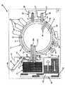
図1は、図2と共に、普通の自動化学分析装置10の構成要素を概略的に示しており、これは、キュベット・ポート72、73の外側キュベット環14と、キュベット・ポート74の内側キュベット環16とを支持している反応回転ラック12を包含し、外側キュベット環14と内側キュベット環16は、開いた溝18によって分離している。キュベット・ポート72、73、74は、小さい、平坦な壁面のある、U字形容器として通常形成される複数の反応キュベット19を受け入れるようになっている。各キュベット・ポートは、底を閉じた開放型中央反応部分と、キュベット19の頂面に対応するところに開口を有し、試薬、サンプルの液体を添加できるようになっている。反応回転ラック12は、一定方向に一定速度で段階的移動を行うように回転できる。この段階的移動は、一定の停滞時間で区切られている。この停滞時間中、回転ラック12は静止状態に維持され、この回転ラック12に近接して設けた分析装置が、キュベット19内に収容されている分析混合物に対して作動することができる。
【0019】
3つの温度制御される試薬保管領域20、22、24が設けてあり、各試薬保管領域は、複数の試薬カートリッジ21を格納している。たとえば、カートリッジ21は、米国特許第4,720,374号に記載され、Dade Behring Inc, Deerfield, IL.によって商品名FLEX(tm)カートリッジとして販売されているものに類似した、必要に応じて所与の分析を実施するための試薬を収容する多区画式試薬容器である。選択的に開放される蓋(図示せず)が、カートリッジ21へアクセスできるように試薬保管領域20、22、24の各々を覆っている。説明を簡単にするために、3つの試薬カートリッジ21のみが、試薬保管領域24のカットアウト部分の下方に配置した状態で、図3に概略的に示してある。しかしながら、同様の試薬カートリッジ21が、試薬保管領域20、22内に配置されている。シャトル手段(図示せず)が、アクセス・ポートを探すように個々のカートリッジ21を移動させる。保管領域20、22は、外側キュベット環14の円周の外側に設置してあり、試薬保管領域24が、内側キュベット環16の円周の内側に設置してあると便利であろう。
【0020】
本発明を実施できるものに類似した臨床分析装置10は、回転ラック12に近接して配置した複数の普通の分析操作ステーションを有する。これらのステーションのところには、周知の臨床分析で必要とされる多種のアクションを実施するのに必要なだけ、センサー、試薬添加ステーション、混合ステーションなどの個々のコンピュータ制御式電気機械装置が設置してある。このような装置およびそれらの動作は、この技術分野では周知であるから、ここで説明する必要はない。たとえば、米国特許第5,876,668号、同第5,575,976号、同第5,482,861号およびこれらの米国特許で引用された引例を参照されたい。
【0021】
反応回転ラック用の割り出し駆動装置が、一定方向に所定数の増分段階で反応容器を移動させる。キュベット環14の円周長さ、キュベット・ポート72、73、74間の分離距離、キュベット・ポート72、73、74の数および一割り出しあたりの増分の数は、一定数の増分段階後に、任意所与のキュベット・ポート72または73または74がその初期出発位置に戻るように選定する。こうすることによって、反応回転ラック14上のすべてのキュベット・ポート72、73、74が、一完全作動サイクル時間(以後、CTとする)内でそれぞれの初期位置に戻る。このCTは、一定数の増分段階×各分析装置での停滞時間の合計および段階的移動に必要な時間で決まる。
【0022】
本発明の主目的は、自動臨床分析装置に与えた異なったサンプルについて実施する必要のある異なった分析の寄せ集めとは無関係に、高い処理能力を達成するように自動臨床分析装置を操作する方法を提供することにある。分析装置10の重要な特徴は、実施されるべき複数の分析を完了するのに必要な時間の長さによって定義されたグループへのこれらの分析の独特な仕分けにある。これらの目的を達成するために、多数の液体吸引・計量分配アーム30、34、36が、試薬保管領域20、22、24に近接して設けてあり、これらのアームは、プログラムされたコンピュータ13、好ましくは、マイクロプロセッサ・ベースの中央演算処理装置(CPU)によって制御され、予めプログラムされたソフトウェア、ファームウェア、またはハードウェアコマンドまたは回路に従って分析装置10のすべての動作を制御する。吸引・計量分配アーム34は、吸引プローブ37を有し、試薬保管領域22内に格納されたカートリッジ21から試薬を取り出し、第1の分析グループのためのキュベット19へ吸引試薬を計量分配するように作動する。第1の分析グループの場合、回転ラック12の完全作動サイクル時間の約半分より短い時間の量で、最終的な培養および検査読み取りが完了し得る。吸引・計量分配アーム30は、同様に、吸引プローブ33を有し、試薬保管領域20内に格納されたカートリッジ21から試薬を取り出し、第2の分析グループのためのキュベット19内へ吸引試薬を計量分配するように作動する。第2の分析グループの場合、回転ラック12の完全作動サイクル時間と第1の分析グループが完了するのに必要な時間との差よりも短い時間の量で、最終的な培養および検査読み取りを分析装置が完了できる。吸引・計量分配アーム36も吸引プローブ40を有し、試薬保管領域24内に格納されたカートリッジ21から試薬を取り出し、最終的な培養および検査読み取りが回転ラック12の完全作動サイクル時間より短い時間の量で完了する分析のためのキュベット19に吸引試薬を計量分配するように作動する。
【0023】
前述のように、分析装置10の動作について重要な特徴としては、分析を完了するのに必要な時間の長さに従って分析を多数のグループに仕分けることがある。説明の助けとするために、第1の分析グループは、以後、Bタイプ分析と呼ぶ。このBタイプ分析は、最終的な読み取りを行うまでに試薬添加および培養を含む完全Bタイプ分析プロセスの完了のためにキュベット環14の作動サイクルCTの約半分より短い時間を必要とするようなすべての分析からなる。タイプA分析と呼ぶ第2の分析グループは、作動サイクルCTの約1/4〜約半分より短い時間を必要とするようなすべての分析からなる。すなわち、この時間は、キュベット環14の完全作動サイクルと、最終的な読み取りが行われるまでの試薬添加および培養を含むそれぞれの分析プロセスを完了するタイプB分析のための時間との差より短い。タイプC分析と呼ぶ第3の分析グループは、タイプA分析またはタイプB分析以外のすべての分析からなる。このような分析は、一般的に、最終的な読み取りが行われるまでの試薬添加および培養を含む完全分析プロセスの完了のための作動サイクルCTの約半分より長い時間を必要とし、完全作動サイクル中、反応回転ラック12上に留まる。注意深く設計した停滞時間および全反応容器数と共に採用された時間によるこのような分析仕分けにより、タイプB分析およびタイプA分析が、完全作動サイクルより短い時間で完全に完了可能であり、この完全作動サイクル中に、一回のタイプCが完全に完了することになる。
【0024】
図2は、キュベット・ポートを使用するために有用なパターンを示している。ここでは、ポート74は、専らタイプC分析の使用に限られ、キュベット環14の円周に沿って等間隔に設けられた1つおきのキュベット・ポート72と半径方向に整合して、キュベット環16の円周に沿って等間隔に設けられている。1つおきのポート74には磁気式分離装置75が組み合わせてあり、これら1つおきのポート74内に設置されたキュベット19内の溶液の磁気分離を可能にしている。それに反して、キュベット・ポート72、73は、タイプC分析、タイプB分析およびAタイプ分析に役立つ。有利な実施例においては、1つおきのキュベット・ポート72は、専らタイプC分析の使用に限られ、それらの間にあるキュベット・ポート72は、専らタイプB、タイプAの分析の使用に限られる。説明の目的のために、キュベット・ポート73には「B/A」というマークが付けてあり、1つのポート72が、まず、Bタイプ分析を実施するのに用いられ、そのタイプB分析が完了した後に、タイプA分析がキュベット・ポート73で実施されることを示している。
【0025】
キュベット装填および取り出しステーション60、62が、外側キュベット回転ラック14に近接して設けてあり、たとえば、並進運動可能なロボット・クランプ63を用いて、内外両方のキュベット回転ラック14、16に形成した、図2に示すキュベット・ポート72、73、74内へキュベット19を慣例通りに装填するようになっている。普通のサンプル処理装置またはステーション17(図3)が、キュベット19にアクセスするために反応回転ラック12まわりの選定円周方向位置に設置してある。ステーション17は、とりわけ、キュベット19内に収容されているサンプル液および試薬を混ぜ合わせる段階、キュベット19内に収容されているサンプル液および試薬液を洗浄する段階、キュベット19内に収容されているフリータグすなわち試薬液からタグ付きの磁性粒子を磁気分離する段階を行うようになっている。
【0026】
検査しようとしている新しいサンプル試料は、サンプル・チューブ移送システム40によって移送され、本発明の譲受人に譲渡された審査中の出願通し番号第09/827045号に記載されているような環境チャンバ44内部、分析装置10内で評価される。試料は、普通、ラック42内に支持された開放チューブ41内に収容され、普通のバーコード・リーダーを用いてサンプル・チューブ41にあるバーコード・マークを読み取ることによって識別され、特に、患者の身元、実施すべき検査、サンプル・アリコートを環境チャンバ44内に保持したいかどうか、もし保持したいならばどのくらいの期間かを決定する。
【0027】
サンプリング・アーム46が、普通の液体サンプリング・プローブ47を支持しており、回転可能な軸48に装着してあり、サンプリング・アーム46の移動が、サンプル・チューブ移送システム40と交差する円弧を描くようになっている。そして、アリコート・ストリップ移送システム49が、図4に示すアリコート・ストリップ45を、反応回転ラック12に近接して設置した一対の普通のサンプル/試薬吸引・計量分配アーム50、52まで移送するようになっている。サンプリング・アーム46は、サンプル・チューブ41から液体サンプルを吸引し、サンプル・アリコートを、必要な分析を実施し、環境チャンバ44内に分析装置10によって保持されるべきサンプル・アリコートを得るのに必要なサンプルの量に依存して、アリコート・ストリップ45にある複数のウェル45Wのうち1つまたはそれ以上のウェルに計量分配するように作動可能である。サンプルをキュベットに計量分配した後、普通の転送手段が、アリコート・ストリップ移送システム49と保管コンパートメント44の間に送るようにアリコート・ストリップ45を移動させる。
【0028】
サンプル吸引・計量分配アーム50、52は、コンピュータ13によって制御され、アリコート・ストリップ45からサンプルを取り出し、検査用のキュベット19に吸引済みのサンプルを計量分配するようになっている。サンプル吸引・計量分配アーム50、52の各々は、それぞれ、一対の普通の液体プローブ53B、53Cおよび54A、54Tを包含する。これらのプローブは、ただ1つの並進移動可能な軸に独立して装着され、並進移動できる。図1には、プローブ53B、53Cが、2つの作動位置にあるように示してあり、一方のプローブ53Bは、アリコート・ストリップ45からのサンプルを取り出し、外側キュベット回転ラック14に設置したタイプB分析検査用のキュベット15Bに吸引済みのサンプルを計量分配するようになっている。プローブ53Cは、アリコート・ストリップ45からサンプルを取り出し、タイプC分析検査用のキュベット15Cに吸引済みのサンプルを計量分配するようになっている。プローブ53Cは、さらに、試薬保管領域24において特別な「コントロール」容器21から液体を取り出すようにもなっている。この「コントロール」容器内には、たとえば、較正済みの溶液が通常の品質保証基準の一部としてオンボードで保持されている。プローブ53B、53C、54A、54Tは、代表的には、試薬を水和し、吸引し、計量分配し、混合するのに使用される超音波機構を包含する。水和、吸引、計量分配、混合用の諸機構は、この技術分野では周知の特徴を有するものであるから、ここでさらに説明する必要はない。
【0029】
プローブ54A、54Tは、図1において、2つの作動位置で示してあり、一方のプローブ54Aは、アリコート・ストリップ45からサンプルを取り出し、外側キュベット回転ラック14に設けたAタイプ分析検査用のポート73においてキュベット19内へ吸引済みのサンプルを計量分配するようになっている。プローブ54Tは、アリコート・ストリップ45からサンプルを取り出し、図示のように反応回転ラック12に近接して設置したイオン選択電極(ISE)テスト・ステーション58に通じるポート56に吸引済みのサンプルを計量分配するようになっている。ISEテスト・ステーション58は、たとえば、ナトリウム、カリウム、クロライドなどのイオンの臨床測定においてイオン選択電極内に分散させた荷電された、または、中性のイオノフォアを使用して、イオン分析物検査を実施するようになっている。このような電極がサンプル溶液にさらされたとき、関連のあるイオンが、選択的に、サンプル溶液から電極へ移送される。これらのイオンと関連した電荷は、サンプル内のイオン内容の濃度あるいは活性度に数学的に関連づけることができる電位を発生する。
【0030】
他の種々の分析手段70を外側キュベット回転ラック14に近接して設けることができる。それにより、キュベット15の光吸収度またはキュベット15の光放射度を種々の波長で測定することができ、これらの値から、周知の分析技術を用いてサンプル液内の分析物の存在を決定することができる。手段70は、代表的には、以下に説明するように、反応回転ラック12が静止している任意の都合の良い時間間隔で、問い合わせ測定を実施するようになっている普通の測光装置、蛍光測定装置または発光測定装置を包含する。
【0031】
軸線まわりに外側反応回転ラック12を独立して回転させる駆動手段が設けてあり、この駆動手段は、代表的には、回転ラック12上に配置してあって、モータの軸上に装着したピニオン歯車と噛み合っている歯車を包含する。この駆動手段は、普通の設計のものであってもよく、図示していない。
【0032】
分析装置10は、Dade Behring Inc, of Deerfield, IL.によって販売され、コンピュータ・ベースの電気機械制御プログラミングの当業者によって広く使用されているDimensionTM臨床化学分析装置で使用されているものと同様に、機械語で記述されたソフトウェアに基づいてコンピュータ13によって制御される。
【0033】
本発明を実施するに際して理解して貰わなければならない重要な要素は、図5、図6に示すものと同様に、種々の分析装置機能タイミングを含む。さらに詳しく説明する目的のために、本発明の一実施例においては、反応回転ラック12は、キュベット・リング14に設けた184個のキュベット・ポート72を包含し、各機械サイクルの初期部分で77個のキュベット位置すべてを単一回転方向(時計方向または反時計方向)において段階的に移動または前進させる。77個のキュベット位置の各段階的移動には、対応する静止停滞時間が続く。1つの段階的移動と次の静止停滞時間との組み合わせは、3.6秒の機械サイクルからなり、時間的に等しくなっており、反応回転ラック12が合計1.8秒間段階的に移動し、次いで、1.8秒間静止するようになっている。184個のキュベット・ポート72の数と各機械サイクルで移動させられる77個のキュベット位置の数との素数関係は、この技術分野では周知であり(米国特許第5,352,612号)、この素数関係から、全部で184回の機械サイクルが生じた後、ありとあらゆるキュベット・ポート72がそのありとあらゆる初期出発位置へ戻り、それによって、184回の3.6秒間の機械サイクルからなる完全回転ラック・サイクルを定めることを決定することができる。こうして、完全回転ラック・サイクルは662.4秒、すなわち、ほぼ11分からなる。図5は、反応回転ラック12、液体吸引、計量分配プローブ33、37、40、53B、53C、54A、54Tについての5つの完全機械サイクルとそこにおける活動量を示している。反応回転ラック12が機械サイクルの最初の半分で1.8秒間移動し、次の半分で1.8秒間静止したままでいるということに注目することは重要である。同様に、液体吸引、計量分配プローブ33、37、40、53B、53C、54A、54Tは、機械サイクルの最初の半分で1.8秒間独立して移動可能であり、次の半分で1.8秒間静止状態に留まる。この機械サイクルの後の半分の間、試薬がキュベット・ポート72内のキュベット19に分散させられ得る。他方、液体吸引、計量分配プローブ33、37、40の下方にカートリッジ19を位置させるシャトル手段は、機械サイクルの最初の半分で1.8秒間静止状態に留まる。この機械サイクルの最初の半分で、試薬が、試薬保管領域20、22、24内の試薬カートリッジ21から吸引され得る。そして、シャトル手段は、機械サイクルの次の半分で1.8秒間、必要に応じて独立して移動できる。他の3つの矢印は、(4)液体吸引、計量分配プローブ33、37、40、53B、53C、54A、54Tが吸引モードにあるとき、試薬容器19が静止状態に留まること、(5)液体吸引、計量分配プローブ33、37、40、53B、53C、54A、54Tが計量分配モードにあり、反応回転ラック12が静止状態に留まっているときに、試薬容器19が移動すること、そして、(6)液体吸引、計量分配プローブ33、37、40、53B、53C、54A、54Tが計量分配モードにおいて静止した直後に試薬容器19が移動を開始することを示している。
【0034】
3つの矢印は、(1)反応回転ラック12が移動するときに、液体吸引、計量分配プローブ33、37、40、53B、53C、54A、54Tが移動すること、(2)反応回転ラック12が停止したとき、計量分配モードにおいて、液体吸引、計量分配プローブ33、37、40、53B、53C、54A、54Tが静止したままとなること、そして、(3)反応回転ラック12が停止した直後に、液体吸引、計量分配プローブ33、37、40、53B、53C、54A、54Tが移動を開始することを示している。
【0035】
図6は、プローブ33、37、40、53C、53Tのうちのどの代表的なものが異なった機械サイクル中に作動できるかを説明している。各機械サイクルは、清浄化洗浄アクションまたは吸引、計量分配の組み合わせアクションのいずれかを含む。清浄化洗浄アクションは、代表的には、全体で3.6秒の機械サイクルから約3.0秒、37のようなプローブの活動経路に設けた普通の洗浄ステーション31を使用する。吸引および計量分配アクションは、各々、個別に、全体で3.6秒の機械サイクルからの全体で約3.0秒うち約1.5秒に相当する。ここで、6つの異なった吸引・計量分配アーム30、32、34、36、50、50の独立した動作に対して、すべてのプローブ33、37、40、53A、53B、53C、54Tが、同じように、それぞれの独立した吸引および計量分配アクションが、各々、個別に、機械サイクル内の約1.5秒に相当するようにしてあることが重要である。IMT検査装置用のポートにサンプルを吸引および計量分配するようになっているプローブ53Tは、単一のチャネルIMT検査装置がただ1つのサンプルについて作動するのに必要な時間のために、清浄化洗浄後の或る時間にわたって、図6に示すように、不作動状態に留まる。IMT検査は低需要分析であるから、代表的には、IMT検査装置はただ1台だけでよいが、処理能力を向上させることがクリニックの要求を満たすのに必要な場合には、複数のチャネルIMT検査装置を使用してもよい。先行のアイドル時間で付加的な吸引および計量分配が生じることになる。
【0036】
図7は、分析装置10によって実施され得る分析を、本発明による3つの時間依存分析カテゴリへの前記仕分けを説明する図である。慣例に従って、時間t=0.0秒は、検査キュベット19に計量分配するサンプルのモーメントとして定義される。説明の簡略化のために、全部で3タイプの分析が、サンプル添加前一定の時刻にただ1回の試薬添加R1を行うものとして示されている。図7は、反応回転ラック12が、184個のキュベット・ポート72を包含し、1.8秒間の移動の後に、1.8秒の静止期間が続く機械サイクル中に全部で77のキュベット位置を反時計方向へ段階的に移動または前進させるこの実施例について、Rfで示す最終読み取りがサンプル添加後約180秒以内で完了する分析フォーマットをすべてのタイプA分析が有することがいかに必要かを示している。ここで、タイプA分析についての最終読み取り時間要求を前述の実施例と異なる分析装置10レイアウトについて調節できることは了解されたい。タイプA分析に分析を仕分けることについて重要なのは、検査装置70によって行われる最終的な分析読み取りが、完全作動サイクル時間、すなわち、180〜220秒の約1/4または1/3より短い時間の量で完了するということである。分析中の任意の時点(Rdで示す)で、反応容器読み取りまたは分析が装置70のうちの任意の装置で行われ得るのである。
【0037】
タイプB分析は、一般的に、タイプA分析よりも複雑であり、1.8秒の移動の後に1.8秒の静止期間が続く機械サイクル中に全部で77のキュベット位置を反時計方向へ段階的に移動または前進させるこの実施例について、サンプル添加後約360秒以内に最終読み取りが完了する分析フォーマットを持つことが必要である。ここで、タイプB分析に対する読み取り時間要求が、上述の実施例と異なる分析装置10レイアウトについて調節できることは了解されたい。分析をタイプB分析に仕分けることにとって重要なことは、検査装置70によって行われる最終的な分析読み取りが、完全作動サイクル時間、すなわち、約360秒のうちの約半分にほぼ等しい時間の量で完了するということである。
【0038】
タイプC分析は、一般的に、タイプA、タイプB分析よりも複雑であり、反応回転ラック12が、184個のキュベット・ポート72を包含し、1.8秒の移動の後に1.8秒の静止期間が続く機械サイクル中に全部で77のキュベット位置を反時計方向へ段階的に移動または前進させるこの実施例について、サンプル添加後約600秒以内に最終的な読み取りが完了する分析フォーマットを有する必要がある。
【0039】
表1は、リストを含む代表的な臨床的な、そして、種々のタイプA、B、C分析についての代表的な臨床免疫測定法のリストを、種々の試薬添加および装置動作に関するタイミングの詳細と共に含んでいる。表1において、
・アルブミン、血液尿素窒素、カルシウム、クレアチニン、γ−グルタミルトランスフェラーゼ、ブドウ糖、乳酸デヒドロゲナーゼ、メタドン、サリチル酸塩および総CO2は、難なくタイプA分析のカテゴリに入り、180秒未満で最終読み取り値が得られる。
・アルカリホスファターゼ、C反応性蛋白、クレアチンキナーゼ、直接ビリルビン、ゲンタマイシン、プレアルブミン、偽コリンエステラーゼ、フェニトイン、リンおよびトリグリセリドは、難なくタイプB分析のカテゴリに入り、360秒未満で最終読み取り値が得られる。
・アンモニア、コレステロールHDL、補体3、ジギトキシン、乳酸、フェノバルビタール、前立腺酸性ホスファターゼ、総ビリルビンおよびトランスフェリンは、タイプC分析のカテゴリに入り、360秒より長い時間で最終読み取り値が得られる。
【0040】
【表1】
さらに理解を得るべく、タイプC分析、タイプB分析、タイプA分析の各々での分析装置10の簡略化した動作を以下に説明する。この別の実施例においては、タイプA分析の場合、試薬保管領域20が試薬容器を包含し、タイプB分析の場合、試薬保管領域22が試薬容器を包含し、タイプC分析の場合、試薬保管領域24が試薬容器21を包含し、そのほか、特殊な試薬スタイル容器が、品質管理用の既知分析物濃度の溶液を収容している。
【0042】
アリコート・ウェル45内にサンプルを収容したキュベット19を装填し、Cタイプ分析を使用して検査する前に、第1の試薬R1を、試薬保管領域24内の試薬容器の適切なコンパートメントからプローブ40によって吸引し、タイプC分析が実施されるように選択し、時刻T1でキュベット・ポート72または74内のキュベット19に入れる。時刻T0で、タイプC分析をオーダーしたサンプルをプローブ53Cによって吸引し、キュベット・ポート74内のキュベット19に入れる。
【0043】
同様にして、アリコート・ウェル45内にサンプルを収容したキュベット19を装填し、タイプB分析を使用して検査する前に、第1の試薬R1を、試薬保管領域22内の試薬容器の適切なコンパートメントからプローブ37によって吸引し、タイプB分析が実施されるように選択し、時刻T1でキュベット・ポート72内のキュベット19に入れる。時刻T0で、タイプB分析をオーダーしたサンプルをプローブ53Bによって吸引し、キュベット・ポート72内のキュベット19に入れる。
【0044】
キュベット・ポート72、74に今述べた試薬およびサンプルを入れた後、反応回転ラック12は、前述した段階的な反時計方向移動を続け、これらの機械サイクル中、種々の普通の分析装置が、適切な分析プロトコルに従ってキュベット・ポート72、74内のキュベット19内の混合物に対して作動する。
【0045】
このような分析すべてが、反応回転ラック12が1つの完全作動サイクル時間CTを完了するのに必要な時間の半分よりも短い時間で完了するようにタイプB分析が仕分けられているので、B分析を完了したキュベット19を、取り出し装置62によって反応回転ラック12の外側キュベット環14にあるキュベット・ポート72から取り出すことができる。次に、未使用のキュベット19を装填装置60によって空のキュベット・ポート72に装填し、分析装置10によって実施されるのに必要な分析タイプの混ざり具合に応じて、二回目のタイプB分析またはタイプA分析について利用できるようにする。アリコート・ウェル45内にサンプルを収容したキュベット19を装填し、タイプA分析を用いて検査する前に、第1の試薬R1を、試薬保管領域20内の試薬容器の適切なコンパートメントからプローブ33によって吸引し、タイプA分析が実施されるように選択し、時刻T1で、図2にB/Aとして示すキュベット・ポート73内のキュベット19に入れる。時刻T0で、タイプA分析をオーダーしたサンプルをプローブ54Aで吸引し、キュベット・ポート73内のキュベット19に入れる。反応回転ラック12は、前述の段階的反時計回り移動を続け、これらの機械サイクル中に、種々の普通の分析装置17が、適切な分析プロトコルに従って、タイプA分析に相当するキュベット・ポート73内およびタイプC分析に相当するキュベット・ポート74内のキュベット19内の混合物に対して作動する。最終的には、完全作動サイクル時間CTを反応回転ラック12が完了し、Aタイプ、Cタイプ両方の分析が完了する。
【0046】
今述べたプロセスを使用して、完全作動サイクル時間CTにわたって完了済みのタイプB分析が反応回転ラック12上に残り、分析装置処理能力の妨げとなる普通の分析装置に比して、本発明は、別の方法を提供する。それによれば、タイプB分析としてここに説明した1つの中間時間長分析およびタイプA分析としてここに説明した1つの短時間長分析が、共に、タイプC分析としてここに説明した1つの長時間長分析が完了するのに必要とするのと同じ作動サイクル時間CT中に完了し、それによって、分析装置処理能力を向上させることができる。
【0047】
あるいは、タイプC分析をオーダーしたサンプルが利用できないために、キュベット・ポート74が空であり、そして、タイプA分析またはタイプB分析のいずれかをオーダーしたサンプルは利用できるが、まだ完了していないという場合には、タイプA分析またはタイプB分析のいずれかをキュベット・ポート74内のキュベット19に入れ、第1の部分サイクル時間CT中にそれを完了することができる。それにより、さらに分析装置10の処理能力を向上させることができる。キュベット・ポート74をタイプA分析で満たしたことを例として挙げると、もしタイプC分析をオーダーしたサンプルがまだ利用できず、そして、追加のタイプA分析についてのサンプルが利用できるが、まだ完了していないならば、そのときには、追加のタイプA分析をキュベット・ポート74内のキュベット19に入れ、第2の部分サイクル時間CT中に完了させることができる。これはさらに分析装置10の処理能力を向上させることができる。
【0048】
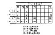
図8は、分析を実施するのに必要なR1、R2、RXで示す試薬添加に依存してタイプD、E、F分析に分析を仕分けする別の例を示している。ここで、記号「R1」は、タイプD分析のための試薬供給源20から採用した初期試薬、タイプE分析のための試薬供給源22から採用された初期試薬、タイプF分析のための試薬供給源24から採用された初期試薬で、サンプル添加前に一定時刻T1で検査キュベットに計量分配された初期試薬を示している。文字「S」は、必要な分析を実施するのに必要なサンプル量に依存して、時刻T0で、タイプD分析についてはプローブ54Aによって、タイプE分析についてはプローブ53Bによって、タイプF分析についてはプローブ53Cによって、アリコート・ストリップ45の複数のウェル45Wの1つまたはそれ以上から達成され得るサンプル添加を示している。同様に、記号「R2」は、タイプE分析のための試薬供給源22から採用された、または、タイプF分析のための試薬供給源24から採用された次の試薬を示しており、この試薬は、サンプル添加S後の一定時刻T2で検査キュベット19に計量分配される。最後に、記号「RX」は、タイプF分析のための試薬供給源24から採用され得る試薬添加(単数または複数)を示しており、これは、サンプル添加Sの前後の可変時刻TXで検査キュベット19に計量分配される。
【0049】
図9は、分析装置10で実施できる分析を、図7、8に示すような時間依存および分析フォーマット依存である3つのカテゴリに仕分けた本発明の別の実施例を示している。慣例通りに、時刻T=0.0秒は、検査キュベット19に計量分配するサンプルのモーメントとして定義される。図9は、すべてのタイプD分析が以下の分析フォーマットを持つようにどのように定義されるかを示している。この分析フォーマットでは、単一の試薬がサンプル添加前の一定時刻T1で検査キュベットに計量分配され、そして、反応回転ラック12が184個のキュベット・ポート72を包含し、1.8秒間の移動の後に1.8秒の静止期間が続く機械サイクル中に全部で77のキュベット位置を反時計方向に段階的に進める分析装置実施例の場合にサンプル添加S後、作動サイクルの約1/4〜1/3以内、すなわち、約180〜220秒以内に最終的な読み取りが完了する。ここで、タイプD分析についての絶対読み取り時間要求が、前述の実施例と異なった分析装置10レイアウトについて調節され得るということは了解されたい。このように分析をタイプD分析に仕分けることにとって重要なことは、検査装置70によって行われる最終分析読み取りが、完全作動サイクル時間の約1/4または1/3の時間よりも短い時間の量で完了するということである。
【0050】
タイプE分析は、一般的に、タイプD分析よりも複雑であり、以下の分析フォーマットを持つように定義される。この分析フォーマットでは、1つの試薬がサンプル添加前の一定時刻T1で検査キュベットに計量分配され、第2の試薬がサンプル添加S後の一定時刻T2で検査キュベットに計量分配され、そして、上述の分析装置構成の場合にサンプル添加S後に作動サイクルの約半分の時間以内、すなわち、約360秒以内に最終読み取りが完了する。ここで、タイプE分析に対する読み取り時間要求が上述の実施例とことなる分析装置10レイアウトについて調節され得るということは了解されたい。分析をタイプE分析に仕分けることについて重要なことは、完全作動サイクル時間の約半分にほぼ等しい時間の量で検査装置70によって行われる最終分析読み取りが完了するということである。
【0051】
タイプF分析は、一般的に、タイプD、タイプE分析よりも複雑であり、以下の分析フォーマットを有するように定義される。この分析フォーマットでは、1つの試薬が、サンプル添加前の一定時刻T1で検査キュベットに計量分配され、第2の試薬が、サンプル添加S後の一定時刻T2で検査キュベットに計量分配され、サンプル添加Sの前後の可変時刻(単数または複数)で付加的な試薬添加(単数または複数)が行われ得、そして、最終的な読み取りが、上述の分析装置構成について或る作動サイクル以内に完了する。
【0052】
さらに詳しく説明するために、タイプF、タイプE、タイプDの各分析での分析装置10の簡略動作を説明する。この別の実施例においては、試薬保管領域20がタイプD分析のための試薬容器を包含し、試薬保管領域22がタイプE分析のための試薬容器を包含し、試薬保管領域24がタイプFF分析のための試薬容器21を包含している。
【0053】
アリコート・ウェル45にサンプルを収容したキュベット19の装填前、そして、タイプF分析を用いて検査する前に、第1の試薬R1が試薬保管領域24内の試薬容器の適切なコンパートメントからプローブ40によって吸引され、タイプF分析が実施されるように選択され、時刻T1でキュベット・ポート72内のキュベット19または74に入れられる。その後、そして、オプションとして、第2の試薬RXが、実施されるべき分析のために選定された試薬容器の別のコンパートメントからプローブ40によって吸引され、任意の時刻TXでキュベット・ポート72内のキュベット19または74に入れられる。時刻T0で、タイプF分析をオーダーしたサンプルが、プローブ53Cによって吸引され、キュベット・ポート74内のキュベット19内に入れられる。図3は、この作動上の融通性を促進するために、キュベット・ポート72、74が、ぞれぞれ、内側キュベット環16および外側キュベット環14内の半径方向に整合させてあることを示している。付加的な試薬(単数または複数)RXは、タイプF分析を実施するように選ばれた試薬容器の別のコンパートメントからプローブ40によって吸引され、時刻T0後、時刻T3前の時刻(単数または複数)TXでキュベット・ポート72内のキュベット19に入れてもよい。
【0054】
同様にして、アリコート・ウェル45にサンプルを収容したキュベット19の装填前で、タイプE分析を使用して検査する前に、第1の試薬R1が、試薬保管領域22内の試薬容器の適切なコンパートメントからプローブ37によって吸引され、タイプE分析が実施されるように選定され、時刻T1でキュベット・ポート72内のキュベット19に入れられる。時刻T0で、タイプE分析をオーダーしたサンプルが、プローブ53Bによって吸引され、キュベット・ポート72内のキュベット19に入れられる。その後、第2の試薬R2が、タイプE分析を実施するように選ばれた試薬容器の別のコンパートメントからプローブ37によって吸引され、時刻T2でキュベット・ポート72内のキュベット19に入れられてもよい。
【0055】
キュベット72、74に今述べた試薬およびサンプルを充填した後、反応回転ラック12は、前述の段階的反時計回り移動を続け、この機械サイクル中に、種々の普通の分析装置が、適切な分析プロトコルに従って、キュベット・ポート72内のキュベット19、74内の混合物に対して作動する。図8に示すように、タイプF分析の場合、付加的な試薬RXは、タイプF分析を実施するように選ばれた試薬容器の別のコンパートメントからプローブ40によって吸引し、時刻T0後で時刻T2前の時刻TXでキュベット・ポート72内のキュベット19に入れてもよい。
【0056】
このような分析のすべてが反応回転ラック12について必要な時間の半分よりも短い時間で完了し、完全作動サイクル時刻CTを完了するようにタイプE分析が仕分けられているために、完了したタイプE分析を含むキュベット19は、取り出し装置62によって反応回転ラック12の外側キュベット環14のキュベット・ポート72から取り出すことができる。次いで、未使用のキュベット19を装填装置60によって空のキュベット・ポート72に装填する。このキュベットは、分析装置10で実施するのに必要な分析タイプの混合物に応じて、第2のタイプE分析またはタイプD分析のために利用できるようなる。アリコート・ウェル45内にサンプルを収容したキュベット19の装填前で、タイプD分析を使用して検査する前に、第1の試薬R1は、試薬保管領域20内の試薬容器の適切なコンパートメントからプローブ33によって吸引され、タイプD分析を実施するように選ばれ、時刻T1で図2にB/Aとして示すキュベット・ポート73内のキュベット19に入れられる。時刻T0で、タイプD分析をオーダーしたサンプルが、プローブ54Aによって吸引され、キュベット・ポート73内のキュベット19に入れられる。反応回転ラック12は、前述の段階的反時計回り移動を続け、これらの機械サイクル中に、適切な分析プロトコルに従って、種々の普通の分析装置17がタイプD分析を含むキュベット・ポート73およびタイプF分析を含むキュベット・ポート74内のキュベット19内の混合物に作動する。最終的に、反応回転ラック12が完全作動サイクル時間CTを完了し、タイプD、タイプF両方の分析が完了する。
【0057】
今述べたプロセスを使用して、完全作動サイクル時間について完了したタイプE分析が反応回転ラック12上に残る普通の分析装置と比較して、本発明は、ここにタイプE分析として説明した、2回の試薬添加を有する1つの中間時間長分析と、ここにタイプD分析として説明した、1回の試薬添加を有する1つの短時間長分析の両方が、ここにタイプF分析として説明した、多数回の試薬添加を有する1つの長時間長分析が完了するのに必要な作動サイクル時間と同じ作動サイクル時間CT中に完了し、それによって、分析装置処理能力が向上する別の方法を提供する。
【0058】
あるいは、タイプF分析をオーダーしたサンプルを利用できないが、タイプD分析またはタイプE分析のいずれかをオーダーしたサンプルが利用でき、そしてまだ完了していないためにキュベット・ポート74が空である場合には、タイプD分析またはタイプE分析のいずれかを、キュベット・ポート74内のキュベット19に置き、最初の部分サイクル時間中に完了させ、分析装置10の処理能力のさらなる向上に貢献させることができる。キュベット・ポート74にタイプD分析を満たした例において、タイプF分析をオーダーしたサンプルをまだ利用できず、そして、付加的なタイプD分析のためのサンプルが利用できるが、まだ完了していない場合には、付加的なタイプD分析をキュベット・ポート74内のキュベット19に置き、第2の部分サイクル時間中に完了させ、分析装置10の処理能力をさらに向上させることもできる。
【0059】
表2は、種々のタイプD、E、F分析のための代表的な臨床免疫測定検体のリストを、種々の試薬添加および装置動作に関するタイミングの詳細と共に示している。
【0060】
表2において、
・アルブミン、 血液尿素窒素、カルシウム、クレアチニン、γ−グルタミルトランスフェラーゼ、ブドウ糖、乳酸デヒドロゲナーゼおよび総CO2は、一定時刻T1での一回の試薬添加および180秒以内の最終読み取りを行うタイプD分析のカテゴリに難なく分類される。
・アルカリホスファターゼ、C反応性蛋白、クレアチンキナーゼ、直接ビリルビン、プレアルブミン、偽コリンエステラーゼ、リンおよびトリグリセリドは、一定時刻T1、T2での一回の試薬添加および360秒以内の最終読み取りを行うタイプE分析のカテゴリに難なく分類される。
・補体3、フェノバルビタール、総ビリルビンおよびトランスフェリンは、一定時刻T1、T2での一回の試薬添加および360秒以内の最終読み取りを行うタイプF分析のカテゴリに分類される。
・アンモニア、コレステロールHDL、ジギトキシン、ゲンタマイシン、乳酸、メタドン、前立腺酸性ホスファターゼ、フェニトインおよびサリチル酸塩は、最終読み取りまでの時間の量に関係なく可変時刻TXで少なくとも一回の試薬添加を行うタイプF分析のカテゴリに分類される。
・補体3は、タイプDまたはEの分析の最終読み取り時刻要求を満たさないので、たとえ一定時刻T1で一回の試薬添加を行うにしても、タイプF分析のカテゴリに分類される。
【0061】
【表2】
単一の分析装置内で無数のこのような分析に対応することは、本技術分野内で普通に行われる作業であって、ここで説明する必要ない。タイプによって分析を仕分け、異なったタイプに専用の試薬保管およびアクセス・プローブを設けるという本発明の教示を、従来達成できなかった分析装置処理能力の向上を達成できるように当業者に提供することのみが必要であるということで充分である。ここで、ここに開示された発明の実施例が、発明の原理を説明するためのものであり、なお発明の範囲内にある他の変形例も使用可能であることは了解されたい。たとえば、キュベット環14が、もっと多いまたはもっと少ない数のキュベット・ポート72を持っていてもよいし、機械サイクル時間を適当に調節してもよいし、付加的な試薬供給源を設けてもよいなど種々の変形が可能であるが、分析が完全に完了するのに必要な時間の長さによって新しいサンプルをグループに仕分け、より長い分析も完了するただ一回の作動サイクル中に中間時間長分析を完了し、反応回転ラックから取り出し、短時間長分析と置き換えるということに影響を与えてはならない。あるいは、新しいサンプルを、分析が完全に完了するのに必要な時間の長さによって採用した試薬添加パターンに従ってグループに仕分け、可変時刻試薬添加を行う長時間長分析も完了するただ1回の作動サイクル中に、2回の一定時刻試薬添加を行う中間時間長分析を完了し、反応回転ラックから取り出し、1回の一定時刻試薬添加を行う短時間長分析に置き換えるようにすることもできる。これらの理由のために、本発明は、本明細書において図示し、説明した実施例そのものに限定されるものではなく、特許請求の範囲によってのみ限定されるものである。
【図面の簡単な説明】
【図1】 本発明を有利に使用できる自動分析装置の概略平面図である。
【図2】 図1の自動分析装置の拡大部分概略平面図である。
【図3】 図1の自動分析装置の拡大部分概略平面図である。
【図4】 図1の自動分析装置内で役立つマルチウェル・アリコート・ストリップの概略立面図である。
【図5】 図1の自動分析装置の各要素運動を示すタイミング図である。
【図6】 図1の自動分析装置の各装置動作を示すタイミング図である。
【図7】 本発明に従って分析時刻で分析タイプを仕分ける実施例を示す図である。
【図8】 本発明に従って試薬添加で分析タイプを仕分けることを説明している図である。
【図9】 本発明に従って分析時刻および試薬添加で分析タイプを仕分ける別の実施例を示す図である。[0001]
【Technical field】
The present invention relates to a method and apparatus for automatically processing a biological fluid (eg, urine, serum, plasma, cerebrospinal fluid, etc.) of a patient. In particular, the present invention provides an improved method of processing patient samples on a single analyzer that is adapted to perform a number of different clinical analyzes using different analysis techniques.
[0002]
BACKGROUND OF THE INVENTION
There are various types of tests related to the diagnosis and treatment of a patient, and these tests can be performed by analysis of a sample of the patient's infection, body fluid or abscess. Such patient samples are typically placed in sample vials, extracted from the vials, mixed with various reagents in specialized reaction vessels or tubes, cultured, analyzed, and helped to treat the patient. It is said. In a typical clinical chemistry analysis, one or two analytical reagents are added to a liquid sample of known concentration at different times. Sample / reagent combinations are mixed and incubated. Interrogation measurements, turbidity measurements, fluorescence measurements, absorbance readings, etc. are taken to determine end point values or rate values and from these values a certain amount of analyte can be determined using well-known calibration techniques can do.
[0003]
While various known clinical analyzers for chemical, immunochemical and biological testing of samples are available, analytical clinical techniques increasingly require the need to improve analytical levels . Automated clinical analyzers improve the efficiency of surgery by providing faster results while minimizing operator or technician error. However, due to the growing demands for analytical processing capabilities in clinical laboratories, new analyzes for additional analytes, accuracy of analytical results and reduced reagent consumption, the overall performance of automated clinical analyzers continues to improve. It has been demanded. In particular, in the case of sample analysis, regardless of the analysis to be performed, improvement in cost efficiency is continually demanded from the viewpoint of the time required for inspection, which is usually shortened by improving the throughput of the analyzer.
[0004]
One important factor in maintaining the throughput of automated analyzers is the ability to rapidly process multiple samples through a variety of different analytical processes and signal measurement stages. If there is enough space in the health care facility, simply install a number of robust components in a dedicated location and implement various analytical techniques to make automatic clinical analyzers capable of high-speed processing and reliability. It will be possible to design with. This is not possible, and there are various criteria for evaluating the throughput rate of an automated clinical analyzer. Volume capacity measurements relate to how long it takes to complete all analyzes for all samples to be tested. In contrast, analytical throughput measurements relate to how much time is required to complete a specific analysis for a specific sample. For example, with respect to volume throughput, 1000 patient samples can be completed in 4 hours, but the first results are available only 3 hours after the start of the exam. However, with regard to analytical throughput, the first analysis result is available in 30 minutes after placing the sample on the analyzer, but the final result is only available 10 hours after the start of the test. Such different throughput is generally unpleasant to the inspector, so the automated analyzer is initially at the same time with high volume throughput in terms of sample analysis / hour. There is a need to have fast turnaround time for reportable results available.
[0005]
One common method of scheduling analysis resources to maximize processing power is based on using a predetermined fixed cycle in which all analysis resources in the instrument operate within a fixed length predetermined cycle. Yes. In a system having this scheduling method, each analysis resource returns to a predetermined position at the end of each cycle. An automated analyzer that uses a predetermined fixed cycle for scheduling resource timing also performs a single chronological operation. Each container containing the sample proceeds through each operating station of the analyzer in the same order. StratusTM The II immunoassay system is such an automatic immunoassay system and is described in volume 41 of J. Clin. Immun. In the Stratus analyzer, a substantially circular reaction rotating rack moves forward by a fixed distance in each cycle of the system, and sequentially determines the culture stage, washing stage, and reading stage in the clockwise direction. A similar process is described in US Pat. No. 5,575,976, where each analytical resource has a predetermined fixed operating window within a fixed processing cycle. As a result, the control for one analysis resource can depend on the predetermined timing of other subordinate and independent analysis resources. Thus, there is no conflict with analyte testing that has a variable protocol and is processed by moving reaction vessels in different chronologies. That is, a short processing time analyte test can be placed after a long processing time analyte test, and a short analyte testing can be completed first. This can be done because the means for moving the reaction vessel containing the analytical components can provide the reaction vessel to the required analytical resources regardless of the order in which they are placed. Because.
[0006]
US Pat. No. 5,434,083 uses a rotating reaction vessel train that sets the analysis time for each of the test items to match the number of cycles (cycles) of the reaction vessel on the reaction line. A reaction vessel update device is selectively controlled for each reaction vessel according to the number of cycles. Thus, inspection items that require a short reaction time are processed with a small number of cycles in the reaction line, and inspection items that require a long reaction time are processed with a higher number of cycles. The analysis apparatus can sequentially process a plurality of inspection items that require different reaction times for one sample.
[0007]
U.S. Pat. No. 5,482,861 deals with an automatic continuous and random access analysis system that can perform multiple analyzes of multiple liquid samples simultaneously. In this system, following the scheduling of various analyzes on a plurality of liquid samples, a first liquid sample and a plurality of reagents are individually added to a reaction vessel without creating an analysis reaction sequence after creating a unit dose. Transfer and then physically transfer the unit dose disposable to the processing workstation so that the unit dose disposable reagent and sample are mixed during incubation.
[0008]
U.S. Pat. No. 5,576,215 deals with biological analyzers, where the instrument system used to perform analysis of biological samples loaded into the analyzer is a scheduler routine. Operated according to the schedule developed by. This scheduler routine determines the time interval between operations performed by the instrument system for each biological sample, unless a fixed time interval between operations is required and schedules the instrument system operation and the determined time interval. Determine as a function of the input load list. The biological system / analyzer performs an analysis of a biological sample by operating an analyzer instrument system according to a developed schedule.
[0009]
U.S. Pat. No. 5,679,309 discloses a method for controlling an analyzer that includes a rotatable circular reaction carousel with circumferentially spaced cuvettes. According to this analyzer menu, each cuvette receives the selected reagents and selected samples for reaction and analysis and is cleaned for reuse after analysis. The drive unit positions the cuvette by indexing the reaction carousel so that it can receive, wash, and analyze reagents and samples in an appropriate sequence according to the menu. When using photometric analysis, the drive is for a certain spin cycle (rotating the reaction carousel for photometric analysis of the reaction cuvette) and time for reactant, sample insertion and / or washing. Operates in a stationary cycle sequence.
[0010]
U.S. Pat. No. 5,846,491 assigns analytical resources to one of a number of reaction vessels as a time cycle function for that vessel, and selects from a plurality of different predetermined chronologies. Throughput is increased by using an analyzer control system with means for transferring reaction vessels directly from one analysis resource station to another according to the technology.
[0011]
US Pat. No. 5,985,672 also uses a preprocessor for use in performing immunoassays on samples for in-sample analytes using concentric culture and processing carousels. To address the need for high-speed processing. A single transfer station allows reaction vessels containing samples and reagents to be moved between carousels. Samples are separated, washed and mixed in a processing carousel, and cultured in a culture carousel. Accordingly, the processing capability is improved.
[0012]
Another scheduling method used in automatic analyzers does not use a fixed cycle, but instead uses a scheduling method called “kitting”. U.S. Pat. No. 6,096,561 discloses an automatic continuous and random access analytical system. This allows multiple analyzes of multiple liquid samples to be performed simultaneously, and various analyzes are scheduled for multiple liquid samples. Through kitting, the system can create unit doses by individually transferring liquid samples and reagents to the reaction vessel without initiating an analytical reaction sequence. From the kitting means, a number of kit unit dose disposables are transferred to the process area where aliquots are one or more at different times for each independent sample in one reaction vessel. To form an independent reaction mixture. Independent scheduling for kitting and mixing occurs simultaneously and independently during the incubation of multiple reaction mixtures. The system can perform two or more scheduled analyzes in any order that provides multiple scheduled analyses. The cultured reaction mixture is analyzed independently and individually by at least two previously scheduled analytical procedures.
[0013]
As can be seen from this description of the state of the art of automated clinical analyzers, although considerable progress has been made to improve processing efficiency, unpredictable combinations of different types of analysis, especially culture and final readings or single and There is still an unmet need for systems and devices that provide high volume throughput for combinations that require various lengths of time to complete an analysis, including multiple reagent additions. Furthermore, the need for a system and apparatus for efficiently completing unpredictable analysis combinations that require relatively long and relatively short processing times has not yet been met.
[0014]
Summary of the Invention
The main object of the present invention is to achieve high throughput when using an automated clinical analyzer, regardless of the collection of different analyzes that need to be performed by the analyzer on the different samples presented to the analyzer. It is to provide a method. The analyzer includes a circular rotatable analytical reaction rotating rack that holds a reaction vessel and can be moved stepwise in a constant rotational direction at a constant speed. Here, the staged movement is separated by a certain stationary stagnation time, during which the analyzer can operate on the analysis mixture contained in the reaction vessel. A clinical analyzer similar to the clinical analyzer in which the present invention can be implemented is typically a plurality of common analytical operation stations (where separate analyzers such as sensors are installed), reagent additions. Station, mixing station, separation station and so on. In the first embodiment of the present invention, during the operation of the analyzer, different new samples that are going to perform different analyzes are put into a number of individual analysis groups according to the length of time required to complete the analysis. Sort. If the analysis is carefully sorted by carefully employed stagnation time, the number of reaction vessels and the location of the analyzer, the first intermediate time length analysis and the second short time will be shorter than a single operating cycle. A time length analysis can be completed, thereby allowing the analyzed reaction mixture to remain on the reaction carousel during non-productive inactivity periods compared to conventional analyzers The volume processing capacity can be improved. In particular, during a single complete operating cycle of a reaction carousel, an intermediate time length analysis is first completed in a number of reaction vessels, and each reaction time is completed after each intermediate time length analysis is completed. It can be removed from the rack and replaced with a new reaction vessel, and then a short length analysis can be completed. The long run analysis stays on the reaction carousel during the entire operating cycle.
[0015]
An indexing drive for the reaction carousel moves the reaction vessel in a certain number of incremental steps in a certain direction. The reaction vessels are located in two concentric circular patterns near the circumference of the reaction carousel and are separated from each other by an even number of equal separation distances. The length of the circular pattern, the separation distance, the number of reaction vessels and the number of increments per index are chosen so that any given reaction vessel returns to its original starting position after a certain number of increments. In this way, all reaction vessels on the reaction carousel within the full operating cycle time (defined by the number of incremental stages x the total stagnation time at each analyzer + the time required for the staged movement) Return to their original position.
[0016]
In another embodiment of the invention, different new samples that are going to perform different analyzes are sorted into multiple groups according to the reagent addition pattern employed along with the length of time required to complete the analysis. . In particular, the sorting of the analysis is such that with the addition of the two reagents at a fixed time relative to the sample addition, a complete analysis of the analyzer is placed in the first analysis group in an amount of time that is less than about half of the full operating cycle time. To be done. Similarly, with the addition of only one reagent at a fixed time for sample addition, with an amount of time that is less than the difference between the full operating cycle time and the time required to complete the first analysis group. All analyzes that the analyzer can complete are placed in a dedicated second analysis group. Finally, at least two reagents are required, one with a fixed time for sample addition, the other with a variable time for sample addition, and at least a full working cycle time to complete the analysis. Are placed in a dedicated third analysis group. In practicing this embodiment of the present invention, after the first analysis group is completed during only one full operating cycle time, the first reaction vessel group is removed from the reaction carousel and the second analysis group. Is replaced.
[0017]
The present invention will be more fully understood from the following detailed description taken in conjunction with the accompanying drawings, which form a part of this application.
[0018]
Detailed Description of the Invention
FIG. 1 together with FIG. 2 schematically shows the components of a conventional
[0019]
Three temperature controlled
[0020]
A
[0021]
An indexing drive for the reaction carousel moves the reaction vessel in a certain number of incremental steps. The circumferential length of the
[0022]
The main object of the present invention is a method of operating an automated clinical analyzer to achieve high throughput independently of the collection of different analyzes that need to be performed on the different samples presented to the automated clinical analyzer. Is to provide. An important feature of the
[0023]
As described above, an important feature of the operation of the
[0024]
FIG. 2 shows a useful pattern for using cuvette ports. Here, the
[0025]
Cuvette loadingand
[0026]
A new sample sample to be examined is transferred by the sample
[0027]
A
[0028]
The sample aspirating / dispensing
[0029]
[0030]
Various other
[0031]
Driving means for independently rotating the outer
[0032]
The
[0033]
Important elements that must be understood in practicing the present invention include various analyzer function timings, similar to those shown in FIGS. For purposes of further explanation, in one embodiment of the present invention, the
[0034]
Three arrows indicate that (1) when the
[0035]
FIG. 6 illustrates which of the
[0036]
FIG. 7 is a diagram for explaining the sorting of the analysis that can be performed by the
[0037]
Type B analysis is generally more complex than Type A analysis, with a total of 77 cuvette positions counterclockwise during a machine cycle followed by a 1.8 second rest period followed by a 1.8 second rest period. For this example of moving or advancing step by step, it is necessary to have an analysis format that completes the final reading within about 360 seconds after sample addition. Here, it should be understood that the read time requirement for Type B analysis can be adjusted for a
[0038]
Type C analysis is generally more complex than Type A, Type B analysis, where the
[0039]
Table 1 includes a list of representative clinical and immunological assays for various types A, B, C analysis including lists, along with timing details for various reagent additions and instrument operation. Contains. In Table 1,
Albumin, blood urea nitrogen, calcium, creatinine, γ-glutamyltransferase, glucose, lactate dehydrogenase, methadone, salicylate and total CO2 Will enter the category of Type A analysis without difficulty and the final reading will be obtained in less than 180 seconds.
Alkaline phosphatase, C-reactive protein, creatine kinase, direct bilirubin, gentamicin, prealbumin, pseudocholinesterase, phenytoin, phosphorus and triglycerides easily enter the category of type B analysis and get a final reading in less than 360 seconds.
Ammonia, cholesterol HDL,
[0040]
[Table 1]
For further understanding, the simplified operation of the
[0042]
Prior to loading the
[0043]
Similarly, before loading the
[0044]
After placing the reagents and samples just described in the
[0045]
Since all such analyzes are type B analyzed so that the
[0046]
Using the process just described, the present invention provides a complete type B analysis that remains on the
[0047]
Alternatively,
[0048]
FIG. 8 shows another example of sorting the analysis into type D, E, and F analysis depending on the reagent addition indicated by R1, R2, and RX necessary to perform the analysis. Here, the symbol “R1” indicates the initial reagent adopted from the
[0049]
FIG. 9 shows another embodiment of the present invention in which the analysis that can be performed by the
[0050]
Type E analysis is generally more complex than type D analysis and is defined to have the following analysis format: In this analysis format, one reagent is dispensed into the test cuvette at a certain time T1 before sample addition, the second reagent is dispensed into the test cuvette at a certain time T2 after sample addition S, and the analysis described above. In the case of the instrument configuration, the final reading is completed within about half the time of the operating cycle after sample addition S, ie within about 360 seconds. It should be understood that the read time requirement for Type E analysis can be adjusted for an
[0051]
Type F analysis is generally more complex than type D, type E analysis and is defined to have the following analysis format: In this analysis format, one reagent is dispensed to the test cuvette at a fixed time T1 before sample addition, and the second reagent is dispensed to the test cuvette at a fixed time T2 after sample addition S. Additional reagent addition (s) can be made at variable time (s) before and after and the final reading is completed within an operating cycle for the analyzer configuration described above.
[0052]
In order to explain in more detail, a simplified operation of the
[0053]
Prior to loading the
[0054]
Similarly, before loading the
[0055]
After filling the
[0056]
All such analyzes are completed for the
[0057]
Using the process just described, the present invention has been described herein as a Type E analysis as compared to a conventional analyzer where a Type E analysis completed for a full operating cycle time remains on the
[0058]
Alternatively, if the sample ordered for Type F analysis is not available, but the sample ordered for either Type D or Type E analysis is available and
[0059]
Table 2 shows a list of representative clinical immunoassay specimens for various types D, E, F analysis, with timing details for various reagent additions and instrument operations.
[0060]
In Table 2,
Albumin, blood urea nitrogen, calcium, creatinine, γ-glutamyltransferase, glucose, lactate dehydrogenase and total CO2 Are easily classified into the category of type D analysis in which a single reagent addition at a fixed time T1 and a final reading within 180 seconds are performed.
-Alkaline phosphatase, C-reactive protein, creatine kinase, direct bilirubin, prealbumin, pseudocholinesterase, phosphorus and triglycerides are type E analysis with one reagent addition at fixed times T1 and T2 and final reading within 360 seconds It is classified without difficulty.
•
Ammonia, cholesterol HDL, digitoxin, gentamicin, lactic acid, methadone, prostatic acid phosphatase, phenytoin and salicylate are of type F analysis with at least one reagent addition at variable time TX regardless of the amount of time to final reading Classified into categories.
Since
[0061]
[Table 2]
Accommodating countless such analyzes within a single analyzer is a routine task within the art and need not be described here. Only provide those skilled in the art with the teaching of the present invention to sort the analysis by type and provide dedicated reagent storage and access probes for different types so as to achieve improvements in analytical instrument throughput not previously achieved. It is enough that is necessary. Here, it is to be understood that the embodiments of the invention disclosed herein are for explaining the principle of the invention, and that other modifications within the scope of the invention can be used. For example, the
[Brief description of the drawings]
FIG. 1 is a schematic plan view of an automatic analyzer that can advantageously use the present invention.
2 is an enlarged partial schematic plan view of the automatic analyzer of FIG. 1. FIG.
3 is an enlarged partial schematic plan view of the automatic analyzer of FIG. 1. FIG.
4 is a schematic elevation view of a multiwell aliquot strip useful in the automated analyzer of FIG. 1. FIG.
FIG. 5 is a timing chart showing each element movement of the automatic analyzer of FIG. 1;
FIG. 6 is a timing chart showing each device operation of the automatic analyzer of FIG. 1;
FIG. 7 is a diagram showing an example in which analysis types are sorted by analysis time according to the present invention.
FIG. 8 is a diagram illustrating sorting of analysis types by reagent addition according to the present invention.
FIG. 9 is a diagram showing another embodiment of sorting analysis types according to the analysis time and reagent addition according to the present invention.
Claims (19)
Translated fromJapanese前記分析装置がキュベット装填および取り出しステーション、サンプル吸引・計量分配アーム、試薬添加ステーションおよび混合ステーション、ならびに分析手段を備え、
前記方法が、実施される分析およびこれらの分析を完了するのに必要な時間の長さに基づいてキュベットを3つの個別のグループに仕分ける段階と、3つの個別のグループのすべての分析を完了する一回の作動サイクル時間にわたって分析装置を作動させる段階であって、ここで前記作動させる段階が、第1の分析および第3の分析をそれぞれ、第1および第3のグループのキュベットにおいて実施することを含む段階と、前記第3の分析を実施しながら前記作動サイクル中に分析装置から前記3つのグループのキュベットのうち第1のグループを取り出す段階と、前記作動サイクル中に第1のグループのキュベットを前記3つのグループのキュベットのうち第2のグループのキュベットに置き換える段階と、前記一回の作動サイクル時間を通じて分析装置上に第3のグループのキュベットを残す段階とを包含する方法。A method of operating an analyzer adapted to perform a number of different analyzes on a plurality of different samples and analytical reagents contained in different reaction cuvettes during a single operating cycle time comprising:
The analyzer comprises a cuvette loading and unloading station, a sample aspiration / dispensing arm, a reagent addition station and a mixing station, and an analysis means;
The methodsorts the cuvettes into three separate groups based on theanalyzes performed and the length of time required to completethese analyses, and completes all analyzes ofthe three individual groups Activating the analytical device for a single actuation cycle time, wherein the actuating step performs the first analysis and the third analysis in the first and third groups of cuvettes, respectively.Removing the first groupof the three groupsof cuvettes from the analyzer during the operating cyclewhile performing the third analysis , and the first groupof cuvettes during the operating cycle. a step of replacing thecuvette of the second group ofcuvettes of the three groups, the one working cycle time Leaving a third groupof cuvettes on the analyzer.
前記分析装置がキュベット装填および取り出しステーション、サンプル吸引・計量分配アーム、試薬添加ステーションおよび混合ステーション、ならびに分析手段を備え、
前記方法が、実施される分析ならびにこれらの分析を完了するのに必要な時間の長さおよび試薬添加パターンに基づいてキュベットを3つの個別のグループに仕分ける段階と、3つの個別のグループのすべての分析が完了する一回の作動サイクル時間にわたって分析装置を作動させる段階であって、ここで前記作動させる段階が、第1の分析および第3の分析をそれぞれ、第1および第3のグループのキュベットにおいて実施することを含む段階と、前記作動サイクル中に分析装置から前記3つのグループのキュベットのうち第1のグループを取り出す段階と、前記作動サイクル中に前記第1のグループのキュベットを前記3のグループのキュベットのうち第2のグループのキュベットと置き換える段階と、前記一回の作動サイクル時間を通じて分析装置上に第3のグループのキュベットを残す段階とを包含する方法。A method of operating an analyzer adapted to perform a number of different analyzes on a plurality of different samples and analytical reagents contained in different reaction cuvettes during a single operating cycle time comprising:
The analyzer comprises a cuvette loading and unloading station, a sample aspiration / dispensing arm, a reagent addition station and a mixing station, and an analysis means;
The method comprising the steps of sorting thecuvette into three separate groups based on the length of time and reagent addition patterns required to complete theanalysis and analysis of theseis performed, allthe three separate groups Activating the analyzer for one operating cycle time to complete the analysis, wherein the actuating step comprises the first analysis and the third analysis, respectively, of the first and third groups of cuvettes. the method comprising performing at the steps of retrieving a first group ofcuvettes of the three groups from the analyzer during said operational cycle, thecuvette of the first group during the operating cycle of the 3 passing a step of replacing thecuvette of the second group, the one working cycle time of a groupof the cuvette Leaving a third groupof cuvettes on the analyzer.
Applications Claiming Priority (3)
| Application Number | Priority Date | Filing Date | Title |
|---|---|---|---|
| US09/917,132US20030040117A1 (en) | 2001-07-27 | 2001-07-27 | Increasing throughput in an automatic clinical analyzer by partitioning assays according to type |
| US10/151,424US7015042B2 (en) | 2001-07-27 | 2002-05-17 | Increasing throughput in an automatic clinical analyzer by partitioning assays according to type |
| PCT/US2002/022960WO2003012454A1 (en) | 2001-07-27 | 2002-07-19 | Increasing throughput in an automatic clinical analyzer by partitioning assays according to type |
Publications (3)
| Publication Number | Publication Date |
|---|---|
| JP2004522979A JP2004522979A (en) | 2004-07-29 |
| JP2004522979A5 JP2004522979A5 (en) | 2008-10-02 |
| JP4374246B2true JP4374246B2 (en) | 2009-12-02 |
Family
ID=26848622
Family Applications (1)
| Application Number | Title | Priority Date | Filing Date |
|---|---|---|---|
| JP2003517594AExpired - Fee RelatedJP4374246B2 (en) | 2001-07-27 | 2002-07-19 | Improve the throughput of automated laboratory analyzers by sorting analysis according to type |
Country Status (8)
| Country | Link |
|---|---|
| US (1) | US7015042B2 (en) |
| EP (1) | EP1325343B1 (en) |
| JP (1) | JP4374246B2 (en) |
| AT (1) | ATE322689T1 (en) |
| DE (1) | DE60210406T2 (en) |
| ES (1) | ES2261707T3 (en) |
| PT (1) | PT1325343E (en) |
| WO (1) | WO2003012454A1 (en) |
Families Citing this family (28)
| Publication number | Priority date | Publication date | Assignee | Title |
|---|---|---|---|---|
| US20060120921A1 (en) | 2002-06-20 | 2006-06-08 | Stuart Elliot | Biological reaction apparatus with draining mechanism |
| AU2003901871A0 (en)* | 2003-03-31 | 2003-05-08 | Vision Biosystems Limited | A method and apparatus for fluid dispensation, preparation and dilation |
| JP3972012B2 (en) | 2003-03-19 | 2007-09-05 | 株式会社日立ハイテクノロジーズ | Sample dispensing mechanism and automatic analyzer equipped with the same |
| JP4033060B2 (en)* | 2003-07-17 | 2008-01-16 | 株式会社日立ハイテクノロジーズ | Automatic analyzer |
| US7381370B2 (en)* | 2003-07-18 | 2008-06-03 | Dade Behring Inc. | Automated multi-detector analyzer |
| US20050014284A1 (en)* | 2003-07-18 | 2005-01-20 | Merrit Jacobs | Improved fluid mixing in a diagnostic analyzer |
| CA2949524C (en) | 2003-07-18 | 2017-07-04 | Bio-Rad Laboratories, Inc. | System and method for multi-analyte detection |
| US7338803B2 (en)* | 2003-07-18 | 2008-03-04 | Dade Behring Inc. | Method for increasing capacity in an automatic clinical analyzer by using modular reagent delivery means |
| US7842504B2 (en) | 2004-04-02 | 2010-11-30 | Siemens Healthcare Diagnostics Inc. | Method for increasing throughput in an automatic clinical analyzer by duplicating reagent resources |
| JP4812352B2 (en)* | 2005-07-21 | 2011-11-09 | 株式会社東芝 | Automatic analyzer and its dispensing method |
| JP4970444B2 (en)* | 2005-07-22 | 2012-07-04 | シーメンス・ヘルスケア・ダイアグノスティックス・インコーポレーテッド | Assay timing in clinical analyzers using cuvette carriers. |
| JP2007057318A (en)* | 2005-08-23 | 2007-03-08 | Olympus Corp | Analyzer, feeder, stirring device and stirring method |
| US20080020469A1 (en)* | 2006-07-20 | 2008-01-24 | Lawrence Barnes | Method for scheduling samples in a combinational clinical analyzer |
| JP5171182B2 (en)* | 2007-09-20 | 2013-03-27 | シスメックス株式会社 | Sample analyzer |
| US8066943B2 (en)* | 2007-11-16 | 2011-11-29 | Siemens Healthcare Diagnostics Inc. | Clinical analyzer having a variable cycle time and throughput |
| JP5431755B2 (en)* | 2008-10-31 | 2014-03-05 | シスメックス株式会社 | Sample analyzer and sample analysis method |
| DE102008058064A1 (en)* | 2008-11-18 | 2010-05-20 | Diasys Diagnostic Systems Gmbh | Automated analyzer with an automatic pipetting device and a pipetting needle rinsing station |
| JP2012526283A (en)* | 2009-05-06 | 2012-10-25 | シーメンス・ヘルスケア・ダイアグノスティックス・インコーポレーテッド | Method and apparatus for low volume analyzers with fixed and variable indexing |
| JP2013122402A (en)* | 2011-12-09 | 2013-06-20 | Canon Inc | Analyzing device for specimen inspection |
| CA2887635C (en) | 2012-10-11 | 2021-01-26 | Siemens Healthcare Diagnostics Inc. | Automation maintenance carrier |
| CN107831324B (en) | 2013-03-15 | 2021-11-19 | 雅培制药有限公司 | Automated diagnostic analyzer with rear accessible track system and related methods |
| EP3149475B1 (en)* | 2014-05-29 | 2021-12-08 | Siemens Healthcare Diagnostics Inc. | Method and apparatus for reducing carryover of reagents and samples in analytical testing |
| JP7120922B2 (en) | 2016-02-17 | 2022-08-17 | ベクトン・ディキンソン・アンド・カンパニー | Automated sample preparation system for diagnostic testing of samples |
| CN207067156U (en) | 2016-04-22 | 2018-03-02 | 贝克顿·迪金森公司 | automated diagnostic analyzer |
| ES2972583T3 (en) | 2016-04-22 | 2024-06-13 | Becton Dickinson Co | Automated diagnostic analyzer and method for its operation |
| JP7179861B2 (en)* | 2018-08-28 | 2022-11-29 | 株式会社日立ハイテク | AUTOMATIC ANALYZER AND METHOD THEREOF |
| CN113219192B (en)* | 2020-01-21 | 2023-10-20 | 深圳迎凯生物科技有限公司 | Reactor transfer process |
| EP4600656A1 (en)* | 2024-02-06 | 2025-08-13 | Hach Lange GmbH | An analytic sample cuvette timer rack and a method for running an analytic sample cuvette timer rack |
Family Cites Families (12)
| Publication number | Priority date | Publication date | Assignee | Title |
|---|---|---|---|---|
| JPS57156543A (en) | 1981-03-24 | 1982-09-27 | Olympus Optical Co Ltd | Device for chemical analysis |
| JPH0690211B2 (en) | 1984-09-21 | 1994-11-14 | オリンパス光学工業株式会社 | Immunological analyzer and method thereof |
| JP2708437B2 (en) | 1987-11-13 | 1998-02-04 | 株式会社日立製作所 | Automatic analyzer |
| US5104808A (en) | 1988-08-26 | 1992-04-14 | Laska Paul F | Method and apparatus for effecting a plurality of assays on a plurality of samples in an automatic analytical device |
| JP2539512B2 (en) | 1989-07-17 | 1996-10-02 | 株式会社日立製作所 | Multi-item analyzer and method for operating the analyzer |
| EP0488247B1 (en) | 1990-11-28 | 1997-04-23 | Hitachi, Ltd. | Analyzing method and apparatus for liquid sample |
| US5576215A (en) | 1991-06-03 | 1996-11-19 | Abbott Laboratories | Adaptive scheduling system and method for operating a biological sample analyzer with variable interval periods |
| US5376313A (en) | 1992-03-27 | 1994-12-27 | Abbott Laboratories | Injection molding a plastic assay cuvette having low birefringence |
| US5380487A (en) | 1992-05-05 | 1995-01-10 | Pasteur Sanofi Diagnostics | Device for automatic chemical analysis |
| US5599501A (en)* | 1994-11-10 | 1997-02-04 | Ciba Corning Diagnostics Corp. | Incubation chamber |
| US5679309A (en) | 1995-12-14 | 1997-10-21 | Beckman Instruments, Inc. | Automated random access analyzer |
| EP0835452B1 (en) | 1996-04-26 | 2005-08-10 | Dade Behring Inc. | Method and apparatus for pre-treating samples in an automatic chemical analyzer |
- 2002
- 2002-05-17USUS10/151,424patent/US7015042B2/ennot_activeExpired - Lifetime
- 2002-07-19ESES02756527Tpatent/ES2261707T3/ennot_activeExpired - Lifetime
- 2002-07-19JPJP2003517594Apatent/JP4374246B2/ennot_activeExpired - Fee Related
- 2002-07-19PTPT02756527Tpatent/PT1325343E/enunknown
- 2002-07-19ATAT02756527Tpatent/ATE322689T1/ennot_activeIP Right Cessation
- 2002-07-19EPEP02756527Apatent/EP1325343B1/ennot_activeExpired - Lifetime
- 2002-07-19DEDE60210406Tpatent/DE60210406T2/ennot_activeExpired - Lifetime
- 2002-07-19WOPCT/US2002/022960patent/WO2003012454A1/enactiveIP Right Grant
Also Published As
| Publication number | Publication date |
|---|---|
| PT1325343E (en) | 2006-08-31 |
| ATE322689T1 (en) | 2006-04-15 |
| JP2004522979A (en) | 2004-07-29 |
| EP1325343A4 (en) | 2004-06-16 |
| EP1325343B1 (en) | 2006-04-05 |
| DE60210406D1 (en) | 2006-05-18 |
| DE60210406T2 (en) | 2006-11-09 |
| US7015042B2 (en) | 2006-03-21 |
| WO2003012454A1 (en) | 2003-02-13 |
| US20030054557A1 (en) | 2003-03-20 |
| EP1325343A1 (en) | 2003-07-09 |
| ES2261707T3 (en) | 2006-11-16 |
Similar Documents
| Publication | Publication Date | Title |
|---|---|---|
| JP4374246B2 (en) | Improve the throughput of automated laboratory analyzers by sorting analysis according to type | |
| US12228583B2 (en) | Automated diagnostic analyzers having vertically arranged carousels and related methods | |
| AU2008234977B2 (en) | Automated multi-detector analyzer | |
| JP2950698B2 (en) | Automatic analyzer with washing function | |
| US8066943B2 (en) | Clinical analyzer having a variable cycle time and throughput | |
| JP2007531881A (en) | Method to increase throughput by duplicating reagent resources in an automated clinical analyzer | |
| US7338803B2 (en) | Method for increasing capacity in an automatic clinical analyzer by using modular reagent delivery means | |
| JP7225382B2 (en) | automatic analyzer | |
| WO2005008217A9 (en) | Method for increasing capacity in an automatic clinical analyzer by using modular reagent delivery means | |
| US20020064881A1 (en) | Method for automatically storing and reprocessing patient specimen's in an automatic clinical analyzer | |
| US20030040117A1 (en) | Increasing throughput in an automatic clinical analyzer by partitioning assays according to type | |
| EP3149475B1 (en) | Method and apparatus for reducing carryover of reagents and samples in analytical testing | |
| US20020064884A1 (en) | Method for automatically storing and reprocessing patient specimen's in an automatic clinical analyzer | |
| US7039561B2 (en) | Outlier rejection method in an automatic clinical analyzer | |
| HK1092761A (en) | Method for increasing capacity in an automatic clinical analyzer by using modular reagent delviery means |
Legal Events
| Date | Code | Title | Description |
|---|---|---|---|
| A621 | Written request for application examination | Free format text:JAPANESE INTERMEDIATE CODE: A621 Effective date:20050318 | |
| A131 | Notification of reasons for refusal | Free format text:JAPANESE INTERMEDIATE CODE: A131 Effective date:20080212 | |
| A601 | Written request for extension of time | Free format text:JAPANESE INTERMEDIATE CODE: A601 Effective date:20080512 | |
| A602 | Written permission of extension of time | Free format text:JAPANESE INTERMEDIATE CODE: A602 Effective date:20080519 | |
| A524 | Written submission of copy of amendment under article 19 pct | Free format text:JAPANESE INTERMEDIATE CODE: A524 Effective date:20080812 | |
| A711 | Notification of change in applicant | Free format text:JAPANESE INTERMEDIATE CODE: A712 Effective date:20081216 | |
| A131 | Notification of reasons for refusal | Free format text:JAPANESE INTERMEDIATE CODE: A131 Effective date:20090210 | |
| RD04 | Notification of resignation of power of attorney | Free format text:JAPANESE INTERMEDIATE CODE: A7424 Effective date:20090225 | |
| A601 | Written request for extension of time | Free format text:JAPANESE INTERMEDIATE CODE: A601 Effective date:20090508 | |
| A602 | Written permission of extension of time | Free format text:JAPANESE INTERMEDIATE CODE: A602 Effective date:20090515 | |
| TRDD | Decision of grant or rejection written | ||
| A01 | Written decision to grant a patent or to grant a registration (utility model) | Free format text:JAPANESE INTERMEDIATE CODE: A01 Effective date:20090825 | |
| A01 | Written decision to grant a patent or to grant a registration (utility model) | Free format text:JAPANESE INTERMEDIATE CODE: A01 | |
| A61 | First payment of annual fees (during grant procedure) | Free format text:JAPANESE INTERMEDIATE CODE: A61 Effective date:20090907 | |
| FPAY | Renewal fee payment (event date is renewal date of database) | Free format text:PAYMENT UNTIL: 20120911 Year of fee payment:3 | |
| R150 | Certificate of patent or registration of utility model | Free format text:JAPANESE INTERMEDIATE CODE: R150 | |
| LAPS | Cancellation because of no payment of annual fees |