JP4373911B2 - Surgical suction adjustment valve - Google Patents
Surgical suction adjustment valveDownload PDFInfo
- Publication number
- JP4373911B2 JP4373911B2JP2004505124AJP2004505124AJP4373911B2JP 4373911 B2JP4373911 B2JP 4373911B2JP 2004505124 AJP2004505124 AJP 2004505124AJP 2004505124 AJP2004505124 AJP 2004505124AJP 4373911 B2JP4373911 B2JP 4373911B2
- Authority
- JP
- Japan
- Prior art keywords
- valve
- valve member
- suction
- valve body
- opening
- Prior art date
- Legal status (The legal status is an assumption and is not a legal conclusion. Google has not performed a legal analysis and makes no representation as to the accuracy of the status listed.)
- Expired - Fee Related
Links
Images


Classifications
- A—HUMAN NECESSITIES
- A61—MEDICAL OR VETERINARY SCIENCE; HYGIENE
- A61M—DEVICES FOR INTRODUCING MEDIA INTO, OR ONTO, THE BODY; DEVICES FOR TRANSDUCING BODY MEDIA OR FOR TAKING MEDIA FROM THE BODY; DEVICES FOR PRODUCING OR ENDING SLEEP OR STUPOR
- A61M1/00—Suction or pumping devices for medical purposes; Devices for carrying-off, for treatment of, or for carrying-over, body-liquids; Drainage systems
- A61M1/71—Suction drainage systems
- A61M1/74—Suction control
- A61M1/742—Suction control by changing the size of a vent
- A—HUMAN NECESSITIES
- A61—MEDICAL OR VETERINARY SCIENCE; HYGIENE
- A61M—DEVICES FOR INTRODUCING MEDIA INTO, OR ONTO, THE BODY; DEVICES FOR TRANSDUCING BODY MEDIA OR FOR TAKING MEDIA FROM THE BODY; DEVICES FOR PRODUCING OR ENDING SLEEP OR STUPOR
- A61M1/00—Suction or pumping devices for medical purposes; Devices for carrying-off, for treatment of, or for carrying-over, body-liquids; Drainage systems
- A61M1/71—Suction drainage systems
- A61M1/74—Suction control
- A61M1/741—Suction control with means for varying suction manually
- A61M1/7411—Suction control with means for varying suction manually by changing the size of a vent
- Y—GENERAL TAGGING OF NEW TECHNOLOGICAL DEVELOPMENTS; GENERAL TAGGING OF CROSS-SECTIONAL TECHNOLOGIES SPANNING OVER SEVERAL SECTIONS OF THE IPC; TECHNICAL SUBJECTS COVERED BY FORMER USPC CROSS-REFERENCE ART COLLECTIONS [XRACs] AND DIGESTS
- Y10—TECHNICAL SUBJECTS COVERED BY FORMER USPC
- Y10S—TECHNICAL SUBJECTS COVERED BY FORMER USPC CROSS-REFERENCE ART COLLECTIONS [XRACs] AND DIGESTS
- Y10S604/00—Surgery
- Y10S604/902—Suction wands
Landscapes
- Health & Medical Sciences (AREA)
- Heart & Thoracic Surgery (AREA)
- Vascular Medicine (AREA)
- Engineering & Computer Science (AREA)
- Anesthesiology (AREA)
- Biomedical Technology (AREA)
- Hematology (AREA)
- Life Sciences & Earth Sciences (AREA)
- Animal Behavior & Ethology (AREA)
- General Health & Medical Sciences (AREA)
- Public Health (AREA)
- Veterinary Medicine (AREA)
- External Artificial Organs (AREA)
- Massaging Devices (AREA)
Abstract
Description
Translated fromJapanese 〔関連出願に対する相互参照〕
本出願は、2002年5月15日に出願されかつ「外科用吸引調節バルブ」(Surgical Suction Regulator Valve)と表題を付された米国特許仮出願番号60/380,304の内容を含みかつ当該仮出願に対する優先権を請求する。[Cross-reference to related applications]
This application contains the contents of US Provisional Patent Application No. 60 / 380,304 filed May 15, 2002 and entitled “Surgery Suction Regulator Valve”. Claim priority to the application.
〔発明の分野〕
本発明は、一般的に調節バルブに関し、より詳細には、吸引チューブと真空源との間に直列に備え付けられ得る外科用吸引調節バルブに関する。(Field of the Invention)
The present invention relates generally to an adjustment valve, and more particularly to a surgical suction adjustment valve that can be installed in series between a suction tube and a vacuum source.
〔発明の背景〕
患者に対する外科手術の進行の間に、手術部位に集まる傾向のある種々の体液(血液を含む)をそこから取り除くことがしばしば必要である。出産の間には、分娩用鼻咽腔吸引装置(intrapartum nasopharyngel suction device)を用いて、胎便を新生児から取り除くことがしばしば必要である。いずれの場合においても、吸引プローブまたはカテーテルは、通常、可撓性チューブによって、ポンプまたは他の型の真空源に接続される。プローブに適用される真空量を調節するために、吸引プローブとポンプとの間に除去バルブを備え付けることが簡便であることが見出されている。このような吸引調節は、通常、周囲の空気の特定流量をチューブの中に入れ、これによりプローブでの吸引力を減少することを可能にするように調整され得るバルブからなる。BACKGROUND OF THE INVENTION
During the course of surgery on a patient, it is often necessary to remove from it various body fluids (including blood) that tend to collect at the surgical site. During childbirth, it is often necessary to remove meconium from the newborn using an intrapartum nasopharyngeal suction device. In either case, the aspiration probe or catheter is typically connected to a pump or other type of vacuum source by a flexible tube. It has been found convenient to provide a removal valve between the aspiration probe and the pump to adjust the amount of vacuum applied to the probe. Such suction regulation typically consists of a valve that can be adjusted to allow a specific flow rate of ambient air into the tube, thereby reducing the suction force at the probe.
いくつかの吸引装置において、調節バルブの空気の取入れは、Pueによる米国特許第5,000,175号に開示されるように、操作者が空気取り入れ口(air−intake)にわたって指を配置することによって調節される。このような装置は、操作者によって絶えることなく操作されなければならない。さらに、操作者が装置を落とすと、最大速度の周囲の空気が許容され、その結果、吸引を低減させるかまたは完全に遮る。 In some suction devices, the intake of the regulating valve air can be caused by the operator placing a finger across the air-intake as disclosed in US Pat. No. 5,000,175 by Pue. Adjusted by. Such devices must be operated continuously by the operator. In addition, when the operator drops the device, ambient air at maximum speed is allowed, resulting in reduced or completely blocked suction.
他の医学的な吸引調節装置(例えば、Jacksonによる米国特許第4,356,823号に開示される装置)は、制限された範囲の真空調整のみを提供し、しかも、空気の取入れの設定を調整可能に安定化させる方法を何ら提供しない。 Other medical suction control devices (eg, the device disclosed in US Pat. No. 4,356,823 by Jackson) provide only a limited range of vacuum adjustments, and also allow for air intake settings. It does not provide any way to adjustably stabilize.
先行技術における同様の吸引調節装置は、片方の手で握られる間に操作することが困難であるかまたは不便であった。また、吸引調節装置は、応力が吸引チューブに適用された場合、不注意な調整に供され得る。 Similar suction control devices in the prior art have been difficult or inconvenient to operate while being grasped by one hand. Also, the suction adjustment device can be subject to inadvertent adjustment when stress is applied to the suction tube.
〔発明の要旨〕
本発明の主要な目的は、外科用の吸引カテーテルと外科用の吸引ポンプあるいは他の型の真空源との間に直列に配置されるべき、簡単でありさらに実用的な調節バルブを提供することであり、この調節バルブは、容易かつ正確に調整され得、そしてその設定を無人で保持し得る。吸引調節バルブが片手で操作され、この吸引調節バルブが非常に単純かつ安価であるので一度使用した後に廃棄され得、そしてこの吸引調節バルブがガンマ線を用いて簡便に滅菌され得る材料で形成されることもまた、本発明の目的である。[Summary of the Invention]
The main object of the present invention is to provide a simple and practical adjustment valve to be placed in series between a surgical suction catheter and a surgical suction pump or other type of vacuum source. The adjustment valve can be easily and accurately adjusted and can keep its settings unattended. The suction control valve is operated with one hand, the suction control valve is so simple and inexpensive that it can be discarded after a single use, and the suction control valve is made of a material that can be sterilized easily using gamma radiation This is also the object of the present invention.
これらの目的および他の目的は、本発明の吸引調節バルブによって達成され、ここでバルブ体は、その中空の内部と連通した略横方向または略円周方向の開口を備え、そしてバルブ部材は、開口が覆われていない開位置とバルブ部材が開口を覆う閉位置との間でバルブ体の外表面上を横方向または円周方向に移動するために、バルブ体の外表面上にスライド可能または回転可能に備え付けられている。バルブ部材は、吸引調節バルブを片手で握る間、操作者の親指または他の指によって、容易かつ正確に操作され得る。吸引調節バルブは、分離された部材であっても、操作部を有しても、吸引棒(wand)または他の吸引装置の一部として組み立てられてもよい。 These and other objects are achieved by the suction regulating valve of the present invention, wherein the valve body comprises a substantially lateral or substantially circumferential opening in communication with its hollow interior, and the valve member comprises: Slidable on the outer surface of the valve body to move laterally or circumferentially on the outer surface of the valve body between an open position where the opening is not covered and a closed position where the valve member covers the opening, or It is equipped to be rotatable. The valve member can be easily and accurately operated by the operator's thumb or other finger while holding the suction adjustment valve with one hand. The suction control valve may be a separate member, may have an operating portion, or may be assembled as part of a suction bar or other suction device.
〔好ましい実施形態の記載〕
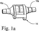
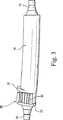
図1について言及すると、本発明の調節バルブ10は、医学的に適切な熱プラスチック(thermal plastic)または他の適切な材料から形成されることが好ましく、そして一般的に、バルブ部14を有する中空体12および吸引チューブ(図示されない)に取り付けられるように適応された先細にされ段が付けられた端部18などを備える中空操作部16を含む。操作部16は、医者または他の使用者の掌の中で、操作部16が容易に適合し得るように、わずかに湾曲され得る。あるいは、図1aに示されるように、操作部16は省略され得、そしてバルブ部14が、その両端に、先細にされ段が付けられた端部18aを備えて提供され得る。[Description of Preferred Embodiment]
Referring to FIG. 1, the regulating
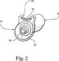
図1〜5に示されるように、バルブ部14は、中空バルブ体20を含み、中空バルブ体20は、窪んだ領域を規定する末端壁22および末端壁22の間で長手方向または軸方向に伸びた止部24を有する、略円形または略楕円形の断面を有する略円筒形構造であり得る。末端壁22の間のバルブ体20の窪んだ外表面26は、バルブ部14の中空内部と連通する任意の適当な形状(図1、図4および図6)の、略横方向または略円周方向の開口28を含む。 As shown in FIGS. 1-5, the
バルブ部材30は、任意の適当な様式で、末端壁22の間でバルブ体20の外表面26上に、回転可能またはスライド可能に備え付けられ、そして、開口28が覆われていない図1〜6に示された開位置とバルブ部材30が開口28を覆う閉位置(図示されない)との間を移動し得る。開位置では、バルブ部材30の一端が、止部24の一方の側面を係合し(図5を参照のこと)、閉位置では、バルブ部材30の他端が、止部24の反対側を係合する。好ましくは、バルブ部材30は、図2、図3および図5に示されるように窪んでいても、図7の132に示されるように窪んでいなくてもよい、節または溝が付けられた外部32を有して提供され、開口28に対してバルブ部材30の位置を調節するために、片手中で保持される間、使用者の親指または他の指によるバルブ部材30の握りおよび移動を容易にする。 The
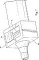
本発明の範囲内において、バルブ体20aは、任意の適当な断面であっても平坦な平面的外表面26aを有してもよく、外表面26aは、図7に示すように、窪んでいても窪んでいなくてもよい。横方向の開口28aが、表面26a中に設けられ、バルブ部材30aが、開口28aを開閉するように、バルブ体表面26a上に、スライド可能に取り付けられている。 Within the scope of the present invention, the valve body 20a may have any suitable cross-section or a flat planar
開口28は、図1および図6に示されるように、開口28が完全には覆われない場合、全ての吸引の開放を容易にするために「鍵穴」形状を有し得る。開口28はまた、横方向の軸または円周方向の軸からわずかに傾いていても離れていてもよく、そして、本発明の原理に従って、「鍵穴」形状以外の任意の適切な形状を有し得る。 The opening 28 may have a “keyhole” shape to facilitate the release of all suction if the
空間が制限される適用について、図1aに示されるように、バルブ体12の操作部16は省略され得る。また、操作部16は、任意の適切なサイズおよび形状であり得る。同様に、バルブ部材30の外部32は、任意の適切なサイズおよび形状であり得る。 For applications where space is limited, the
バルブ部材30およびバルブ体20は、バルブ体20に対するバルブ部材30の制御された漸増移動およびバルブ部材の所望の場所での制御された保持を提供するための任意の適切な様式で構成され得る。例示的な実例として、図6に示されるように、バルブ体20の窪んだ表面26は、溝28の両側に、円周方向に間隔をあけてならんだ複数の凹部40を有して提供され得る。バルブ部材30の内表面は、バルブ部材の漸増移動およびバルブ部材の所望の位置での保持を提供するために、凹部40中にしっかりと噛み合うべく配置された凸部42を有して提供される。 Valve
図8は、本発明の第2の実施形態を例示し、ここで、本発明の吸引調節バルブ110は、吸引棒または吸引装置150の一部として構築されており、この吸引棒または吸引装置150は、吸引カテーテル、すなわち、バルブ110の一方の側面に接続された先端部152、バルブ110の別の側面に接続された中空操作部154、および吸引ポンプに接続するために操作部154の外側端部に接続される接続部156(図示されない)などを含む。操作部154は、省略され得、そして接続部156は、バルブ110に直接接続され得る。 FIG. 8 illustrates a second embodiment of the present invention, where the
バルブ部材30およびバルブ体20は、バルブ部材30が開口28を覆う閉位置にある場合、開口28を介する漏れまたは吸引の損失を防止するために、バルブ部材30およびバルブ体20が密着してかみ合うことを確実にするための任意の適切な様式で構成され得る。例えば、バルブ部材30は、可撓性でありかつ弾力性のある材料で形成され得、その結果、バルブ部材30は、閉位置にある場合に開口28を介する吸引によってバルブ体20との封着した接触の中に引き込まれる。代替として、バルブ体表面26近傍の止部24の一部が、図9において25として示されるような先細の窪みを有して提供され得、そしてバルブ部材30が閉位置にある場合、止部24に隣接するバルブ部材30の一部は、バルブ部材が、バルブ体20の隣接する外表面との強固に密着するかみ合い中に内向きに押し込まれるように閉位置に移動される場合に、窩25において受容される相補的に先細にされた端部27を有して提供され得る。When the
本発明の吸引調節バルブの利点のいくつかは、以下である:
1.開口28の略横方向または略円周方向は、他の外科用のツール(例えば、吸引棒など)の中に小さなサイズまたは幅のバルブ部14を組み込むことを容易にし得る;
2.バルブ部材30の横方向または円周方向の移動は、その軸方向または長手方向の移動よりも、バルブ部材30に接続された吸引チューブにおいて引力(pull)が存在する場合の不注意な移動を妨げる助けとなる;
3.バルブ部材は、使用者の一方の手によって容易に操作され得、任意の方向で吸引チューブに接続され得る;
4.バルブ部材30は、吸引バルブが片手に保持される間、開口28の全てまたは一部を覆うあるいは全く覆わないように、使用者の親指または他の指によって容易に異動され得る;
5.バルブは、単純な構成であり、製造するために容易かつ安価であり、操作において信頼性があり、かつ吸引装置中への設置が容易である。Some of the advantages of the suction control valve of the present invention are the following:
1. The generally lateral or generally circumferential direction of the
2. Lateral or circumferential movement of the
3. The valve member can be easily manipulated by one hand of the user and can be connected to the suction tube in any direction;
4). The
5. The valve is simple in construction, easy and inexpensive to manufacture, reliable in operation and easy to install in the suction device.
本発明は、最も実用的でありかつ好ましい実施形態であると現在みなされているものと共に記載されているが、本発明が開示された実施形態に限定されず、添付の特許請求の範囲の精神および範囲内に含まれる種々の改変および等価な組み合わせを包含することが意図されることが理解されなければならない。 While the invention has been described in conjunction with what is presently considered to be the most practical and preferred embodiments, the invention is not limited to the disclosed embodiments, and the spirit of the appended claims It should be understood that various modifications and equivalent combinations included within the scope and range are intended to be included.
Claims (1)
Translated fromJapanese外側端部の間で伸びる中空内部を備える長手方向の軸を備える中空バルブ体であって、該外側端部上に、該外科吸引カテーテルと該外科吸引ポンプとに取り付けるための連結部材を有するとともに、該中空内部と連通し、該長手方向の軸を横切るように伸びる細長い開口を備える外表面を備える中空バルブ体;および
該細長い開口に隣接した状態で、該バルブ体の該外表面上で該長手方向の軸を横切るように移動するために該バルブ体上にスライド可能に取り付けられたバルブ部材であって、該バルブ部材は、該開口が覆われていない開位置と該バルブ部材が該開口を覆いかつ閉じる閉位置との間を移動し得る、バルブ部材;
を備え、
該バルブ部材が、該閉位置にある場合に、該バルブ体の隣接した外表面と密着してかみ合い、
該バルブ体が、該バルブ部材の開閉移動を制限するための止部を備え、該止部は、該バルブ部材が、該バルブ体の該隣接した外表面との密着したかみ合い中に押し込まれるように該閉位置に移動される場合に、該バルブ部材の該隣接する端部を受けるように配置されている窩を、該バルブ体の該外表面の近傍に有し、
該止部中の該窩および該バルブ体の該隣接する端部が、相補的な様式で先細にされている、吸引調節バルブ。Surgical suction adjustment, suitably sized with a medically suitable plastic material, and installed between a surgical suction pump and a surgical suction catheter and adapted to remove body fluid during the course of a surgical procedure A valve, which is:
A hollow valve body having a longitudinal shaft with a hollow interior extending between outer ends, having a connecting member on the outer end for attachment to the surgical suction catheter and the surgical suction pump A hollow valve body having an outer surface with an elongated opening in communication with the hollow interior and extending across the longitudinal axis; and on the outer surface of the valve body adjacent to the elongated opening; A valve member slidably mounted on the valve body for movement across a longitudinal axis, the valve member having an open position where the opening is uncovered and the valve member being in the opening A valve member capable of moving between a closed position covering and closing;
With
When the valve member is in the closed position, it engages closely with the adjacent outer surface of the valve body;
The valve body includes a stop for restricting the opening and closing movement of the valve member so that the valve member is pushed into close contact with the adjacent outer surface of the valve body. In the vicinity of the outer surface of the valve body, the fovea being arranged to receive the adjacent end of the valve member when moved to the closed position;
A suction control valve, wherein the fossa in the stop and the adjacent end of the valve body are tapered in a complementary manner.
Applications Claiming Priority (3)
| Application Number | Priority Date | Filing Date | Title |
|---|---|---|---|
| US38030402P | 2002-05-15 | 2002-05-15 | |
| US10/287,546US6875198B2 (en) | 2002-05-15 | 2002-11-05 | Surgical suction regulator valve |
| PCT/US2003/009434WO2003097129A1 (en) | 2002-05-15 | 2003-03-27 | Surgical suction regulator valve |
Publications (2)
| Publication Number | Publication Date |
|---|---|
| JP2005525197A JP2005525197A (en) | 2005-08-25 |
| JP4373911B2true JP4373911B2 (en) | 2009-11-25 |
Family
ID=29423253
Family Applications (1)
| Application Number | Title | Priority Date | Filing Date |
|---|---|---|---|
| JP2004505124AExpired - Fee RelatedJP4373911B2 (en) | 2002-05-15 | 2003-03-27 | Surgical suction adjustment valve |
Country Status (9)
| Country | Link |
|---|---|
| US (2) | US6875198B2 (en) |
| EP (1) | EP1553994B1 (en) |
| JP (1) | JP4373911B2 (en) |
| CN (1) | CN100589848C (en) |
| AT (1) | ATE544478T1 (en) |
| AU (1) | AU2003222094B2 (en) |
| CA (1) | CA2485742C (en) |
| ES (1) | ES2382151T3 (en) |
| WO (1) | WO2003097129A1 (en) |
Families Citing this family (32)
| Publication number | Priority date | Publication date | Assignee | Title |
|---|---|---|---|---|
| WO2005111042A1 (en)* | 2004-05-03 | 2005-11-24 | Janssen Pharmaceutica N.V. | Novel indole derivatives as selective androgen receptor modulators (sarms) |
| US7588533B2 (en)* | 2004-11-26 | 2009-09-15 | Joanne Drysdale | Sexual therapy device |
| US20070287933A1 (en)* | 2006-06-08 | 2007-12-13 | Chris Phan | Tissue debulking device and method of using the same |
| US8414550B2 (en) | 2006-09-29 | 2013-04-09 | Lexion Medical, Llc | System and method to vent gas from a body cavity |
| US7913693B2 (en)* | 2006-11-10 | 2011-03-29 | Nellcor Puritan Bennett Llc | Method and apparatus for preventing occlusion of a tracheal tube suction lumen |
| US8585646B2 (en)* | 2008-03-03 | 2013-11-19 | Lexion Medical, Llc | System and method to vent gas from a body cavity |
| CA2729201C (en) | 2008-06-27 | 2016-06-21 | Davol, Inc. | Endoscopic vacuum controller |
| US8597228B2 (en)* | 2009-03-09 | 2013-12-03 | Thermedx, Llc | Fluid deficit monitoring in a fluid management system |
| US9474848B2 (en) | 2009-03-09 | 2016-10-25 | Thermedx, Llc | Fluid management system |
| US9775664B2 (en)* | 2009-09-22 | 2017-10-03 | Mederi Therapeutics, Inc. | Systems and methods for treating tissue with radiofrequency energy |
| EP2593024A1 (en)* | 2010-07-17 | 2013-05-22 | The New York And Presbyterian Hospital | Methods and systems for minimally invasive endoscopic surgeries |
| DE102011052196B4 (en)* | 2011-07-27 | 2017-06-08 | MAQUET GmbH | Device for aspirating liquids and / or particles from body orifices |
| USD668410S1 (en) | 2011-11-11 | 2012-10-02 | Telebrands Corp. | Vacuum cleaner attachment adapter |
| USD681894S1 (en) | 2012-01-12 | 2013-05-07 | Telebrands Corp. | Vacuum adapter for lint removal |
| US9775672B2 (en)* | 2012-08-31 | 2017-10-03 | Nico Corporation | Bi-polar surgical instrument |
| US10383680B2 (en)* | 2012-08-31 | 2019-08-20 | Nico Corporation | Bi-polar surgical instrument |
| CN103285506B (en)* | 2013-05-13 | 2016-04-13 | 常熟市精亮微医疗器械科技有限公司 | Novel clamp type drain valve |
| US9770541B2 (en) | 2014-05-15 | 2017-09-26 | Thermedx, Llc | Fluid management system with pass-through fluid volume measurement |
| WO2016005894A1 (en)* | 2014-07-07 | 2016-01-14 | Promev S.R.L. | Pressure reducer for surgical aspiration systems |
| EP3200706A4 (en)* | 2014-10-02 | 2018-06-20 | George Crawford | Suction adapter device |
| US10166036B2 (en)* | 2014-10-16 | 2019-01-01 | Gyrus Acmi, Inc. | Variable suction control |
| US9872943B1 (en) | 2015-03-30 | 2018-01-23 | The United States Of America As Represented By The Secretary Of The Air Force | Pistol grip suction device |
| DE102016014241A1 (en) | 2016-11-30 | 2018-05-30 | Karl Storz Se & Co. Kg | Medical suction regulator |
| DE102017124927A1 (en) | 2017-10-25 | 2019-04-25 | Irasun Gmbh | Vacuum assisted venous drainage system (VAVD) |
| US11191885B2 (en)* | 2018-12-06 | 2021-12-07 | Joshua C. Arnone | Flow control system |
| US12042175B2 (en)* | 2019-02-13 | 2024-07-23 | Stryker European Operations Limited | Bone material harvesting device |
| CN114945392A (en) | 2019-11-08 | 2022-08-26 | 瑟梅德斯有限责任公司 | Fluid management system and method |
| PL3936168T3 (en)* | 2020-07-10 | 2025-06-02 | Bo Karlsmose | A suction control handle comprising a cover element |
| USD978346S1 (en) | 2022-08-12 | 2023-02-14 | Br Surgical, Llc | Separated finger pad for a surgical suction instrument |
| CN115969556B (en)* | 2022-12-21 | 2025-03-28 | 首都医科大学宣武医院 | A secretion adsorption regulation system and method |
| US11992600B1 (en)* | 2022-12-23 | 2024-05-28 | James R. Newkirk Agency, Inc. | Fluid management device and system |
| US20250235222A1 (en)* | 2024-01-24 | 2025-07-24 | Boston Scientific Scimed, Inc. | Medical devices with passive and active drains |
Family Cites Families (32)
| Publication number | Priority date | Publication date | Assignee | Title |
|---|---|---|---|---|
| US3395705A (en) | 1965-10-18 | 1968-08-06 | American Hospital Supply Corp | Medical suction apparatus |
| US3625221A (en)* | 1969-07-29 | 1971-12-07 | Sherwood Medical Ind Inc | Flap-trol suction catheter |
| US3834388A (en) | 1973-01-29 | 1974-09-10 | Cenco Medical Health Supply Co | Suction control arrangement for a suction catheter |
| US3863635A (en)* | 1974-02-22 | 1975-02-04 | Den Tal Ez Mfg Co | Vacuum handpiece including integral vacuum valve |
| US5000175A (en) | 1979-08-08 | 1991-03-19 | Pue Alexander F | Meconium aspiration device |
| US4356823A (en) | 1980-05-30 | 1982-11-02 | Jackson Richard R | Suction control |
| US4445517A (en)* | 1981-09-28 | 1984-05-01 | Feild James Rodney | Suction dissector |
| JPS58133229A (en)* | 1982-02-02 | 1983-08-08 | オリンパス光学工業株式会社 | Suction change-over valve of endoscope |
| US4662871A (en) | 1984-09-18 | 1987-05-05 | Stephen Rafelson | Disposable suction catheter and system for providing multiple suctioning capabilities during medical procedures or the like |
| US4964849A (en)* | 1986-01-06 | 1990-10-23 | Francis Robicsek | Two-way suction apparatus for surgical procedures |
| US4784649A (en)* | 1987-03-20 | 1988-11-15 | The Cooper Companies, Inc. | Surgical aspirator cannula |
| US5127694A (en)* | 1990-03-03 | 1992-07-07 | The Triangle Tool Group | Vacuum manipulator |
| US4878900A (en) | 1988-07-27 | 1989-11-07 | Sundt Thoralf M | Surgical probe and suction device |
| US5203769A (en)* | 1989-11-06 | 1993-04-20 | Mectra Labs, Inc. | Medical device valving mechanism |
| US4961245A (en)* | 1990-02-05 | 1990-10-09 | Ryobi Motor Products Corp. | Suction controlling arrangement in a canister vacuum cleaner |
| US5084045A (en)* | 1990-09-17 | 1992-01-28 | Helenowski Tomasz K | Suction surgical instrument |
| FR2676365B1 (en)* | 1991-05-13 | 1993-08-20 | Gerard Adhoute | SUCTION DEVICE FOR PEROPERATIVE SELF-TRANSFUSION. |
| US5169192A (en)* | 1991-06-28 | 1992-12-08 | H-Square Corporation | Electronic article pickup tool |
| US5335655A (en)* | 1992-09-10 | 1994-08-09 | Sherwood Medical Company | Suction control valve |
| US5320328A (en) | 1993-08-09 | 1994-06-14 | Sherwood Medical Company | Suction control valve with vacuum breaker |
| US5676136A (en)* | 1993-12-07 | 1997-10-14 | Russo; Ronald D. | Protective suction control catheter with valve |
| US5531712A (en) | 1994-09-30 | 1996-07-02 | Malcolm; Roger J. | Surgical suction regulator valve |
| US5730727A (en)* | 1995-06-12 | 1998-03-24 | Russo; Ronald D. | Thumb conformable suction control regulator |
| US5704090A (en)* | 1995-09-08 | 1998-01-06 | Shop Vac Corporation | Bleed for a vacuum cleaner |
| US5890516A (en)* | 1996-08-12 | 1999-04-06 | Talamonti; Anthony R. | Stomach suction pump connector valve |
| US5836909A (en)* | 1996-09-13 | 1998-11-17 | Cosmescu; Ioan | Automatic fluid control system for use in open and laparoscopic laser surgery and electrosurgery and method therefor |
| USD412984S (en) | 1997-01-17 | 1999-08-17 | Stryker Corporation | Surgical suction regulator |
| US5899884A (en) | 1997-01-17 | 1999-05-04 | Stryker Corporation | Suction regulator |
| US5919174A (en) | 1997-02-03 | 1999-07-06 | Sorenson Critical Care, Inc. | Suction valve assembly |
| US5993410A (en)* | 1997-07-08 | 1999-11-30 | Cabot Technology Corporation | Adjustable probe |
| US6364853B1 (en)* | 2000-09-11 | 2002-04-02 | Scion International, Inc. | Irrigation and suction valve and method therefor |
| US6343823B1 (en)* | 2000-10-23 | 2002-02-05 | William G. Busby | Vacuum pickup tool |
- 2002
- 2002-11-05USUS10/287,546patent/US6875198B2/ennot_activeExpired - Fee Related
- 2003
- 2003-03-27JPJP2004505124Apatent/JP4373911B2/ennot_activeExpired - Fee Related
- 2003-03-27AUAU2003222094Apatent/AU2003222094B2/ennot_activeCeased
- 2003-03-27CACA2485742Apatent/CA2485742C/ennot_activeExpired - Fee Related
- 2003-03-27WOPCT/US2003/009434patent/WO2003097129A1/enactiveApplication Filing
- 2003-03-27EPEP03718080Apatent/EP1553994B1/ennot_activeExpired - Lifetime
- 2003-03-27ATAT03718080Tpatent/ATE544478T1/enactive
- 2003-03-27ESES03718080Tpatent/ES2382151T3/ennot_activeExpired - Lifetime
- 2003-03-27CNCN03810874Apatent/CN100589848C/ennot_activeExpired - Fee Related
- 2005
- 2005-02-11USUS11/055,104patent/US7611490B2/ennot_activeExpired - Lifetime
Also Published As
| Publication number | Publication date |
|---|---|
| EP1553994B1 (en) | 2012-02-08 |
| CA2485742C (en) | 2010-11-02 |
| JP2005525197A (en) | 2005-08-25 |
| AU2003222094B2 (en) | 2008-01-31 |
| AU2003222094A1 (en) | 2003-12-02 |
| US7611490B2 (en) | 2009-11-03 |
| EP1553994A1 (en) | 2005-07-20 |
| ES2382151T3 (en) | 2012-06-05 |
| CA2485742A1 (en) | 2003-11-27 |
| CN1652830A (en) | 2005-08-10 |
| HK1078038A1 (en) | 2006-03-03 |
| WO2003097129A1 (en) | 2003-11-27 |
| US6875198B2 (en) | 2005-04-05 |
| EP1553994A4 (en) | 2010-03-31 |
| US20050148937A1 (en) | 2005-07-07 |
| US20030216690A1 (en) | 2003-11-20 |
| CN100589848C (en) | 2010-02-17 |
| ATE544478T1 (en) | 2012-02-15 |
Similar Documents
| Publication | Publication Date | Title |
|---|---|---|
| JP4373911B2 (en) | Surgical suction adjustment valve | |
| US4487600A (en) | Adjustable suction device for medical use | |
| US6533797B1 (en) | Control grip assembly | |
| EP1991288B1 (en) | Endoscopic suction device | |
| US20060212056A1 (en) | Surgical instrument | |
| US4263911A (en) | Hand actuated medical suction apparatus | |
| WO2006119512A2 (en) | Surgical tool and insertion device for tube placement | |
| BR112015023010B1 (en) | FLUID EVACUATION DEVICE | |
| US20240139458A1 (en) | Tracheal intubation device for delivery of apneic oxygenation and suction | |
| EP1894585B1 (en) | Adjustable aspiration device | |
| US4966584A (en) | Suction aspirator with noise-control valve | |
| US8512233B2 (en) | Curved laryngoscope and operation instrument assembly applying the same | |
| JP2509231B2 (en) | Medical suction device | |
| BRPI0502376A (en) | Enhanced Adjustable Fluid Bandage | |
| US6638240B2 (en) | Surgical suction instrument | |
| CN113648512B (en) | Remotely adjustable drainage tube fixing sleeve clamp | |
| US7722627B2 (en) | Surgical ligation instrument | |
| KR100978339B1 (en) | Surgical Suction Regulator Valve | |
| HK1078038B (en) | Surgical suction regulator valve | |
| CN110193128A (en) | A kind of pressure adjustable type aspirator tube | |
| JPH045136Y2 (en) | ||
| CN216317945U (en) | A neurosurgical suction device with electrocoagulation function | |
| CN218186889U (en) | An ultrasonic scalpel aerosol suction kit | |
| JPH071122Y2 (en) | Endoscope | |
| JP2019193738A (en) | Medical tool |
Legal Events
| Date | Code | Title | Description |
|---|---|---|---|
| RD02 | Notification of acceptance of power of attorney | Free format text:JAPANESE INTERMEDIATE CODE: A7422 Effective date:20050704 | |
| A521 | Request for written amendment filed | Free format text:JAPANESE INTERMEDIATE CODE: A821 Effective date:20050704 | |
| A621 | Written request for application examination | Free format text:JAPANESE INTERMEDIATE CODE: A621 Effective date:20060120 | |
| A131 | Notification of reasons for refusal | Free format text:JAPANESE INTERMEDIATE CODE: A131 Effective date:20081104 | |
| A521 | Request for written amendment filed | Free format text:JAPANESE INTERMEDIATE CODE: A523 Effective date:20090204 | |
| A131 | Notification of reasons for refusal | Free format text:JAPANESE INTERMEDIATE CODE: A131 Effective date:20090331 | |
| A521 | Request for written amendment filed | Free format text:JAPANESE INTERMEDIATE CODE: A523 Effective date:20090520 | |
| A131 | Notification of reasons for refusal | Free format text:JAPANESE INTERMEDIATE CODE: A131 Effective date:20090616 | |
| A521 | Request for written amendment filed | Free format text:JAPANESE INTERMEDIATE CODE: A523 Effective date:20090717 | |
| TRDD | Decision of grant or rejection written | ||
| A01 | Written decision to grant a patent or to grant a registration (utility model) | Free format text:JAPANESE INTERMEDIATE CODE: A01 Effective date:20090818 | |
| A01 | Written decision to grant a patent or to grant a registration (utility model) | Free format text:JAPANESE INTERMEDIATE CODE: A01 | |
| A61 | First payment of annual fees (during grant procedure) | Free format text:JAPANESE INTERMEDIATE CODE: A61 Effective date:20090904 | |
| FPAY | Renewal fee payment (event date is renewal date of database) | Free format text:PAYMENT UNTIL: 20120911 Year of fee payment:3 | |
| R150 | Certificate of patent or registration of utility model | Free format text:JAPANESE INTERMEDIATE CODE: R150 | |
| LAPS | Cancellation because of no payment of annual fees |