JP4373702B2 - Moving picture encoding apparatus, moving picture decoding apparatus, moving picture encoding method, moving picture decoding method, moving picture encoding program, and moving picture decoding program - Google Patents
Moving picture encoding apparatus, moving picture decoding apparatus, moving picture encoding method, moving picture decoding method, moving picture encoding program, and moving picture decoding programDownload PDFInfo
- Publication number
- JP4373702B2 JP4373702B2JP2003129333AJP2003129333AJP4373702B2JP 4373702 B2JP4373702 B2JP 4373702B2JP 2003129333 AJP2003129333 AJP 2003129333AJP 2003129333 AJP2003129333 AJP 2003129333AJP 4373702 B2JP4373702 B2JP 4373702B2
- Authority
- JP
- Japan
- Prior art keywords
- motion vector
- frame image
- target
- reference frame
- adjacent
- Prior art date
- Legal status (The legal status is an assumption and is not a legal conclusion. Google has not performed a legal analysis and makes no representation as to the accuracy of the status listed.)
- Expired - Lifetime
Links
Images


Classifications
- H—ELECTRICITY
- H04—ELECTRIC COMMUNICATION TECHNIQUE
- H04N—PICTORIAL COMMUNICATION, e.g. TELEVISION
- H04N19/00—Methods or arrangements for coding, decoding, compressing or decompressing digital video signals
- H04N19/50—Methods or arrangements for coding, decoding, compressing or decompressing digital video signals using predictive coding
- H04N19/503—Methods or arrangements for coding, decoding, compressing or decompressing digital video signals using predictive coding involving temporal prediction
- H04N19/51—Motion estimation or motion compensation
- H04N19/513—Processing of motion vectors
- H—ELECTRICITY
- H04—ELECTRIC COMMUNICATION TECHNIQUE
- H04N—PICTORIAL COMMUNICATION, e.g. TELEVISION
- H04N19/00—Methods or arrangements for coding, decoding, compressing or decompressing digital video signals
- H04N19/50—Methods or arrangements for coding, decoding, compressing or decompressing digital video signals using predictive coding
- H04N19/503—Methods or arrangements for coding, decoding, compressing or decompressing digital video signals using predictive coding involving temporal prediction
- H04N19/51—Motion estimation or motion compensation
- H04N19/56—Motion estimation with initialisation of the vector search, e.g. estimating a good candidate to initiate a search
- H—ELECTRICITY
- H04—ELECTRIC COMMUNICATION TECHNIQUE
- H04N—PICTORIAL COMMUNICATION, e.g. TELEVISION
- H04N19/00—Methods or arrangements for coding, decoding, compressing or decompressing digital video signals
- H04N19/10—Methods or arrangements for coding, decoding, compressing or decompressing digital video signals using adaptive coding
- H04N19/102—Methods or arrangements for coding, decoding, compressing or decompressing digital video signals using adaptive coding characterised by the element, parameter or selection affected or controlled by the adaptive coding
- H04N19/103—Selection of coding mode or of prediction mode
- H04N19/109—Selection of coding mode or of prediction mode among a plurality of temporal predictive coding modes
- H—ELECTRICITY
- H04—ELECTRIC COMMUNICATION TECHNIQUE
- H04N—PICTORIAL COMMUNICATION, e.g. TELEVISION
- H04N19/00—Methods or arrangements for coding, decoding, compressing or decompressing digital video signals
- H04N19/10—Methods or arrangements for coding, decoding, compressing or decompressing digital video signals using adaptive coding
- H04N19/134—Methods or arrangements for coding, decoding, compressing or decompressing digital video signals using adaptive coding characterised by the element, parameter or criterion affecting or controlling the adaptive coding
- H04N19/136—Incoming video signal characteristics or properties
- H04N19/137—Motion inside a coding unit, e.g. average field, frame or block difference
- H—ELECTRICITY
- H04—ELECTRIC COMMUNICATION TECHNIQUE
- H04N—PICTORIAL COMMUNICATION, e.g. TELEVISION
- H04N19/00—Methods or arrangements for coding, decoding, compressing or decompressing digital video signals
- H04N19/10—Methods or arrangements for coding, decoding, compressing or decompressing digital video signals using adaptive coding
- H04N19/169—Methods or arrangements for coding, decoding, compressing or decompressing digital video signals using adaptive coding characterised by the coding unit, i.e. the structural portion or semantic portion of the video signal being the object or the subject of the adaptive coding
- H04N19/17—Methods or arrangements for coding, decoding, compressing or decompressing digital video signals using adaptive coding characterised by the coding unit, i.e. the structural portion or semantic portion of the video signal being the object or the subject of the adaptive coding the unit being an image region, e.g. an object
- H04N19/172—Methods or arrangements for coding, decoding, compressing or decompressing digital video signals using adaptive coding characterised by the coding unit, i.e. the structural portion or semantic portion of the video signal being the object or the subject of the adaptive coding the unit being an image region, e.g. an object the region being a picture, frame or field
- H—ELECTRICITY
- H04—ELECTRIC COMMUNICATION TECHNIQUE
- H04N—PICTORIAL COMMUNICATION, e.g. TELEVISION
- H04N19/00—Methods or arrangements for coding, decoding, compressing or decompressing digital video signals
- H04N19/44—Decoders specially adapted therefor, e.g. video decoders which are asymmetric with respect to the encoder
- H—ELECTRICITY
- H04—ELECTRIC COMMUNICATION TECHNIQUE
- H04N—PICTORIAL COMMUNICATION, e.g. TELEVISION
- H04N19/00—Methods or arrangements for coding, decoding, compressing or decompressing digital video signals
- H04N19/50—Methods or arrangements for coding, decoding, compressing or decompressing digital video signals using predictive coding
- H04N19/503—Methods or arrangements for coding, decoding, compressing or decompressing digital video signals using predictive coding involving temporal prediction
- H04N19/51—Motion estimation or motion compensation
- H04N19/513—Processing of motion vectors
- H04N19/517—Processing of motion vectors by encoding
- H04N19/52—Processing of motion vectors by encoding by predictive encoding
- H—ELECTRICITY
- H04—ELECTRIC COMMUNICATION TECHNIQUE
- H04N—PICTORIAL COMMUNICATION, e.g. TELEVISION
- H04N19/00—Methods or arrangements for coding, decoding, compressing or decompressing digital video signals
- H04N19/50—Methods or arrangements for coding, decoding, compressing or decompressing digital video signals using predictive coding
- H04N19/503—Methods or arrangements for coding, decoding, compressing or decompressing digital video signals using predictive coding involving temporal prediction
- H04N19/51—Motion estimation or motion compensation
- H04N19/573—Motion compensation with multiple frame prediction using two or more reference frames in a given prediction direction
Landscapes
- Engineering & Computer Science (AREA)
- Multimedia (AREA)
- Signal Processing (AREA)
- Compression Or Coding Systems Of Tv Signals (AREA)
- Compression, Expansion, Code Conversion, And Decoders (AREA)
Description
Translated fromJapanese【0001】
【発明の属する技術分野】
本発明は、動画像符号化装置、動画像復号化装置、動画像符号化方法、動画像復号化方法、動画像符号化プログラム及び動画像復号化プログラムに関するものである。
【0002】
【従来の技術】
従来の動画像符号化方式の事例として、H.264/AVC符号化方式に基づく動画像符号化装置及び動画像復号化装置が挙げられる(非特許文献1参照)。この方式は、動き補償フレーム間予測により時間方向に存在する冗長度を削減し、直交変換によりさらに空間方向に残る冗長度を削減することで動画像(入力映像信号)の情報圧縮を行うというものである。
【0003】
上記方式における動き補償フレーム間予測(以下、「INTER予測モード」と言う。)では、動きベクトルを検出する参照フレーム画像を複数用意することができるため、符号化対象領域の周囲の符号化済み領域の動きベクトルは、それぞれ異なる参照フレーム画像を用いて動き補償されている場合がある。
【0004】
また、符号化対象領域の予測動きベクトルを算出する際、周囲の符号化済み領域の動きベクトルがどの参照フレーム画像から動き補償されていたかによらず、それらの動きベクトルの値を比較して、それらの中間値を符号化対象の領域の動きベクトル予測値としている。
【0005】
【非特許文献1】
Joint Video Team (JVT) of ISO/IEC MPEG and ITU-VCEG , "Editor's Proposed Draft Text Modifications for Joint Video Specification (ITU-T Rec.H.264 | ISO/IEC 14496-10 AVC) , Geneva modifications draft 37"
【0006】
【発明が解決しようとする課題】
しかしながら、このように周囲の符号化済み領域が符号化対象領域の参照フレーム画像と異なる参照フレーム画像を用いて動き補償されていた場合、それらの中間値を予測動きベクトルとして用いると参照フレームの違いから実際の動きベクトルから大きく外れ、符号化の情報圧縮の効率が低下するという問題がある。また、それに伴って、復号化の情報圧縮の効率も同時に低下するという問題もある。
【0007】
本発明は、上記課題を解決するために成されたものであり、符号化及び復号化の情報圧縮の効率の向上を図ることが可能な動画像符号化装置、動画像復号化装置、動画像符号化方法、動画像復号化方法、動画像符号化プログラム及び動画像復号化プログラムを提供することを目的とする。
【0008】
【課題を解決するための手段】
本発明の動画像符号化装置は、フレーム画像信号の時間系列で構成される動画像信号における符号化対象のフレーム画像を複数の対象領域に分割し、対象領域毎に、符号化対象のフレーム画像と異なる複数のフレーム画像を参照して動きベクトルを検出することにより、動き補償による符号化を行う動画像符号化装置において、対象領域に隣接する隣接領域の動きベクトルに基づいて最適予測動きベクトルを決定し、最適予測動きベクトルとして決定された隣接領域の動きベクトルの隣接参照フレーム画像と、対象領域の動きベクトルを検出するために参照された対象参照フレーム画像と、符号化対象のフレーム画像である対象フレーム画像との時間的な関係又はそれらの時刻情報に基づいて、対象参照フレーム画像を基準にして最適予測動きベクトルをスケーリングして補正する動きベクトル予測手段と、対象フレーム画像及び対象参照フレーム画像間の動きベクトルと、動きベクトル予測手段により補正された最適予測動きベクトルとから算出された値であり、符号化され圧縮ストリームとして伝送される情報を求める手段とを有することを特徴とする。
【0009】
また、本発明の動画像符号化方法は、フレーム画像信号の時間系列で構成される動画像信号における符号化対象のフレーム画像を複数の対象領域に分割し、対象領域毎に、符号化対象のフレーム画像と異なる複数のフレーム画像を参照して動きベクトルを検出することにより、動き補償による符号化を行う動画像符号化方法において、動きベクトル予測手段が、対象領域に隣接する隣接領域の動きベクトルに基づいて最適予測動きベクトルを決定するステップと、最適予測動きベクトルとして決定された隣接領域の動きベクトルの隣接参照フレーム画像と、対象領域の動きベクトルを検出するために参照された対象参照フレーム画像と、符号化対象のフレーム画像である対象フレーム画像との時間的な関係又はそれらの時刻情報に基づいて、対象参照フレーム画像を基準にして最適予測動きベクトルをスケーリングして補正するステップと、対象フレーム画像及び対象参照フレーム画像間の動きベクトルと、補正された最適予測動きベクトルとから算出された値であり、符号化され圧縮ストリームとして伝送される情報を求めるステップとを有することを特徴とする。
【0010】
また、本発明の動画像符号化プログラムは、フレーム画像信号の時間系列で構成される動画像信号における符号化対象のフレーム画像を複数の対象領域に分割し、対象領域毎に、符号化対象のフレーム画像と異なる複数のフレーム画像を参照して動きベクトルを検出することにより、動き補償による符号化処理をコンピュータに実行させる動画像符号化プログラムにおいて、コンピュータを、対象領域に隣接する隣接領域の動きベクトルに基づいて最適予測動きベクトルを決定し、最適予測動きベクトルとして決定された隣接領域の動きベクトルの隣接参照フレーム画像と、対象領域の動きベクトルを検出するために参照された対象参照フレーム画像と、符号化対象のフレーム画像である対象フレーム画像との時間的な関係又はそれらの時刻情報に基づいて、対象参照フレーム画像を基準にして最適予測動きベクトルをスケーリングして補正する動きベクトル予測手段、対象フレーム画像及び対象参照フレーム画像間の動きベクトルと、動きベクトル予測手段により補正された最適予測動きベクトルとから算出された値であり、符号化され圧縮ストリームとして伝送される情報を求める手段、として機能させることを特徴とする。
【0011】
本発明の動画像符号化装置、動画像符号化方法及び動画像符号化プログラムによれば、動きベクトル予測手段が、隣接領域の動きベクトルに基づいて最適予測動きベクトルを決定した後、決定された最適予測動きベクトルを、対象領域の動きベクトルを検出するために参照されたフレーム画像と符号化対象のフレーム画像との時間差を基準としてスケーリングして補正するので、実際の対象領域の動きベクトルと予測動きベクトルの差をより小さくすることができるとともに、動きベクトルを予測するための処理時間を短縮することが可能となる。
【0014】
本発明の動画像復号化装置は、フレーム画像信号の時間系列で構成される動画像信号における復号化対象のフレーム画像を複数の対象領域に分割し、対象領域毎に復号化対象のフレーム画像と異なる複数のフレーム画像を参照して検出された動きベクトルと予測動きベクトルとの差分情報を利用することにより、動き補償による復号化を行う動画像復号化装置において、対象領域に隣接する隣接領域の動きベクトルに基づいて最適予測動きベクトルを決定し、最適予測動きベクトルとして決定された隣接領域の動きベクトルの隣接参照フレーム画像と、対象領域の動きベクトルを検出するために参照された対象参照フレーム画像と、符号化対象のフレーム画像である対象フレーム画像との時間的な関係又はそれらの時刻情報に基づいて、対象参照フレーム画像を基準にして最適予測動きベクトルをスケーリングして補正する動きベクトル予測手段と、対象フレーム画像及び対象参照フレーム画像間の動きベクトルと予測動きベクトルとから算出された値に対して、動きベクトル予測手段により補正された最適予測動きベクトルを用いた演算を行うことにより動きベクトルを復元する手段とを有することを特徴とする。
【0015】
また、本発明の動画像復号化方法は、フレーム画像信号の時間系列で構成される動画像信号における復号化対象のフレーム画像を複数の対象領域に分割し、対象領域毎に復号化対象のフレーム画像と異なる複数のフレーム画像を参照して検出された動きベクトルと予測動きベクトルとの差分情報を利用することにより、動き補償による復号化を行う動画像復号化方法において、動きベクトル予測手段が、対象領域に隣接する隣接領域の動きベクトルに基づいて最適予測動きベクトルを決定するステップと、最適予測動きベクトルとして決定された隣接領域の動きベクトルの隣接参照フレーム画像と、対象領域の動きベクトルを検出するために参照された対象参照フレーム画像と、符号化対象のフレーム画像である対象フレーム画像との時間的な関係又はそれらの時刻情報に基づいて、対象参照フレーム画像を基準にして最適予測動きベクトルをスケーリングして補正するステップと、対象フレーム画像及び対象参照フレーム画像間の動きベクトルと予測動きベクトルとから算出された値に対して、補正された最適予測動きベクトルを用いた演算を行うことにより動きベクトルを復元するステップとを有することを特徴とする。
【0016】
また、本発明の動画像復号化プログラムは、フレーム画像信号の時間系列で構成される動画像信号における復号化対象のフレーム画像を複数の対象領域に分割し、対象領域毎に復号化対象のフレーム画像と異なる複数のフレーム画像を参照して検出された動きベクトルと予測動きベクトルとの差分情報を利用することにより、動き補償による復号化処理をコンピュータに実行させる動画像復号化プログラムにおいて、コンピュータを、対象領域に隣接する隣接領域の動きベクトルに基づいて最適予測動きベクトルを決定し、最適予測動きベクトルとして決定された隣接領域の動きベクトルの隣接参照フレーム画像と、対象領域の動きベクトルを検出するために参照された対象参照フレーム画像と、符号化対象のフレーム画像である対象フレーム画像との時間的な関係又はそれらの時刻情報に基づいて、対象参照フレーム画像を基準にして最適予測動きベクトルをスケーリングして補正する動きベクトル予測手段、対象フレーム画像及び対象参照フレーム画像間の動きベクトルと予測動きベクトルとから算出された値に対して、動きベクトル予測手段により補正された最適予測動きベクトルを用いた演算を行うことにより動きベクトルを復元する手段として機能させることを特徴とする。
【0017】
本発明の動画像復号化装置、動画像復号化方法及び動画像復号化プログラムによれば、動きベクトル予測手段が、隣接領域の動きベクトルに基づいて最適予測動きベクトルを決定した後、決定された最適予測動きベクトルを、対象領域の動きベクトルを検出するために参照されたフレーム画像と符号化対象のフレーム画像との時間差を基準としてスケーリングして補正するので、実際の対象領域の動きベクトルと予測動きベクトルの差をより小さくすることができるとともに、動きベクトルを予測するための処理時間を短縮することが可能となる。
【0020】
【発明の実施の形態】
本発明の実施形態にかかる動画像符号化装置及び動画像復号化装置について図面を参照して説明する。なお、各図において、同一要素には同一符号を付して重複する説明を省略する。
【0021】
[第1実施形態]
図1は、本実施形態にかかる動画像符号化装置の一例を示す概略図、図3は、本実施形態にかかる動画像復号化装置の一例を示す概略図である。
【0022】
(動画像符号化装置の構成)
まず、図1を用いて、本発明にかかる動画像符号化装置10について説明する。以下に説明する動画像符号化装置10は、H.264/AVC符号化方式に準拠した符号化装置である。
【0023】
ここで、動画像符号化装置10に入力される動画像信号としての入力映像信号(動画像信号)は、フレーム画像の時間系列で構成されている。また、フレーム画像信号は、この入力映像信号のフレーム画像単位の信号を表すものとする。以下、符号化対象のフレーム画像信号を「現フレーム」と呼ぶ。現フレームは、16画素×16ライン固定の正方矩形領域であるマクロブロックに分割され、マクロブロック単位で、以下の符号化処理及び復号化処理が行われる。
【0024】
H.264/AVC符号化方式では、マクロブロックごとに、予測モードとして、フレーム画像信号と時間的に異なる複数の符号化済みフレーム画像信号(参照フレーム画像信号)を参照して動きベクトルを検出することにより、動き補償フレーム間予測を行う複数の「INTER予測モード」と、同一空間上の符号化済みである近傍のマクロブロックの画素値を用いた空間予測を行う複数の「INTRA予測モード」とが用意されている。なお、「INTER予測モード」においては、マクロブロックをさらに任意の領域(例えば、8画素×16ライン)に分割したブロック(対象領域)毎に動き検出、動き予測、及び動き補償の各処理(詳細は後述する。)が行われる。動画像符号化装置10は、入力映像信号の局所的な性質に応じてマクロブロック単位で予測モードを切り替え、効率的な情報圧縮を行うことができるように構成されている。
【0025】
動画像符号化装置10は、機能的な構成要素として、図1に示すように、入力部101と、動き検出部102と、動き補償部103と、フレームメモリ104と、空間予測部105と、スイッチ106と、減算器107と、直交変換部108と、量子化部109と、可変長符号化部110と、逆量子化部111と、逆直交変換部112と、加算器113とを備えて構成される。以下、各構成要素について説明する。
【0026】
入力部101は、外部から入力される動画像信号としての入力映像信号121を受信した後フレーム画像信号に分解し、減算器107及び動き検出部102に対して、フレーム画像信号122、123として送る部分である。
【0027】
また、フレームメモリ104は、過去に符号化済みのフレーム画像信号を記憶しておく部分である。
【0028】
動き検出部102は、予測モードの選択と動きベクトルの検出を行う部分である。より具体的には、動き検出部102は、「INTER予測モード」を選択した場合、参照フレーム画像信号124を用いて、あらかじめフレームメモリに蓄積されている複数の符号化済みフレーム画像の中から所定の探索範囲内で、現フレーム内の画像信号パターンに類似する画像信号パターンを探し出す。そして、両画像信号パターン間の空間的な変位量である動きベクトルを検出する。検出された動きベクトルと符号化済みの隣接ブロックの動きベクトルから算出する最適予測動きベクトル(動きベクトル予測値)との差分情報である動きベクトル差分値と、動きベクトルの検出に用いた参照フレーム画像信号を示す参照フレーム番号と、選択された予測モードとを含む信号125を可変長符号化部110へ送る。同時に、動き検出部102は、選択された予測モードと、動きベクトルと、参照フレーム番号とを含む信号126を動き補償部103に送る。
【0029】
また、動き補償部103は、動き検出部102から送られた動きベクトルを用いて、フレームメモリ104中の参照フレーム番号で示されるフレームの符号化済み画像信号(参照フレーム画像信号)を参照して、各ブロックの予測画像信号127を生成し、スイッチ106に送る。
【0030】
一方、動き検出部102は、「INTRA予測モード」を選択した場合、選択された予測モード128を空間予測部105に送る。この場合、動き検出部102は同一空間上の符号化済みである近傍のブロックの画素値を用いた空間予測を行うため、時間的な動きに関する情報である動きベクトル差分値および参照フレーム番号を可変長符号化部110へ送ることは行わない。
【0031】
これに対して、空間予測部105は、符号化済みである近傍のブロックの画像信号(参照フレーム画像信号129)を参照して、予測画像信号130を生成し、スイッチ106に送る。
【0032】
スイッチ106は、動き検出部102から受信した予測モード131に応じて、予測画像信号127と予測画像信号130のいずれかを選択し、選択した予測画像信号132を減算器107に送る。
【0033】
これに対して、減算器107は、フレーム画像信号122と予測画像信号132との差分値(予測残差信号133)を生成し、直交変換部108に送る。
【0034】
直交変換部108は、減算器107から送られた予測残差信号133を直交変換することにより、直交変換係数134を生成して、量子化部109に送る。
【0035】
これに対して、量子化部109が、直交変換部108から送信された直交変換係数134を量子化することにより、量子化直交変換係数135を生成し、可変長符号化部110及び逆量子化部111に送る。
【0036】
次に、可変長符号化部110が、量子化部109から送信された量子化直交変換係数135と、動き検出部102から送信された予測モードと、動きベクトル差分値と、参照フレーム番号とに基づいてエントロピー符号化を行って圧縮ストリーム136に多重化して、外部へ伝送する。
【0037】
また、逆量子化部111は、量子化部109から送信された量子化直交変換係数135について逆量子化を行うことにより、直交変換係数137を生成して、逆直交変換部112に送る。
【0038】
そして、逆直交変換部112は、逆量子化部111から送信された直交変換係数137について逆直交変換を行うことにより、予測残差信号138を生成し、加算器113に送る。
【0039】
加算器113は、逆直交変換部112から送信された予測残差信号138とスイッチ106から送信された予測画像信号132とを加算してフレーム画像信号139を生成し、フレームメモリ104に送る。このフレーム画像信号139が、フレームメモリ104に格納され、以降の符号化処理で、参照フレーム画像信号として用いられる。また、動きベクトルや参照フレーム番号に関する情報も参照フレーム画像信号に含んで同時に格納される。
【0040】
次に、図2を参照して、動画像符号化装置10の動き検出部102について詳細に説明する。図2は、図1の動き検出部の構成図である。
【0041】
動き検出部102は、機能的な構成要素として、図2に示すように、予測モード決定部201と、参照フレーム決定部202と、動きベクトル検出部203と、動きベクトル予測部(動きベクトル予測手段)204と、動きベクトル差分部205とを備えて構成される。
【0042】
まず、予測モード決定部201は、入力されたフレーム画像信号123および参照フレーム画像信号124に基づき、符号化対象の所定ブロックの符号化モードとして「INTER予測モード」を用いるか「INTRA予測モード」を用いるかを判断し、予測モードを決定する。「INTRA予測モード」を選択した場合は、予測モード131を出力し、処理を終了する。「INTER予測モード」を選択した場合、予測モード決定部201は、予測モード131を出力すると同時に、フレーム画像信号と、参照フレーム画像信号と、予測モードとを含む信号210を参照フレーム決定部202に送る。
【0043】
参照フレーム決定部202は、入力されたフレーム画像信号と、参照フレーム画像信号と、および予測モードとに基づき、符号化対象の所定ブロックの動きベクトルの検出および予測を行う参照フレームを決定し、フレーム画像信号と参照フレーム画像信号と予測モードと参照フレーム番号とを含む信号211を動きベクトル検出部203に送る。同時に、参照フレーム決定部202は、参照フレーム画像信号と予測モードと参照フレーム番号とを含む信号212を動きベクトル予測部204に送る。
【0044】
動きベクトル検出部203は、入力されたフレーム画像信号、参照フレーム画像信号、予測モードおよび参照フレーム番号に基づき、参照フレーム画像信号の中の参照フレーム番号が示す画像信号から、現フレーム内の画像信号パターンに類似する画像信号パターンを探し出す。そして、両画像信号パターン間の空間的な変位量である動きベクトルを検出し、その動きベクトルと予測モードと参照フレーム番号とを含む信号213を動きベクトル差分部205に送る。また、動き補償に用いるための動きベクトルと、予測モードと、参照フレーム番号とを含む信号126を出力する。
【0045】
また、動きベクトル予測部204は、参照フレーム画像信号に含まれる符号化対象の所定ブロックに隣接する符号化済みのブロックの動きベクトルおよびそれらの参照フレーム番号と、符号化対象の所定ブロックの予測モードおよび参照フレーム番号を用いて、符号化対象の所定ブロックの動きベクトル予測値を算出する。なお、動きベクトル予測値の算出の際には、符号化対象の所定ブロックの動きベクトルを検出するために参照されたフレーム画像(対象参照フレーム画像)を基準にして、符号化対象の所定ブロックに隣接するブロックの動きベクトルをスケーリングする補正を行う(詳細は、後述する。)。スケーリングは、隣接するブロックの動きベクトルを検出するために参照されたフレーム画像(隣接参照フレーム画像)と、対象参照フレーム画像と、符号化対象のフレーム画像(対象フレーム画像)との時間的な関係に基づいて行う。ここで、隣接参照フレーム画像と対象参照フレーム画像と対象フレーム画像との時間的な関係とは、各フレーム画像の相対的な時間差、又は各フレーム画像の時刻情報を示している。動きベクトル予測部204は、算出した動きベクトル予測値と予測モードと参照フレーム番号とを含む信号215を、動きベクトル差分部205に送る。
【0046】
動きベクトル差分部205は、入力された動きベクトルから動きベクトル予測値を引いた値である動きベクトル差分値を算出し、可変長符号化される予測モードと、参照フレーム番号と、動きベクトル差分値とを含む信号125を出力する。
【0047】
(動画像復号化装置の構成)
次に、図3を用いて、本発明にかかる動画像復号化装置30について説明する。以下に説明する動画像復号化装置30は、動画像符号化装置10と同様に、H.264/AVC符号化方式に準拠した復号化装置である。
【0048】
動画像復号化装置30は、動画像符号化装置10により出力された圧縮ストリーム136を入力信号として用い、これを入力映像信号に復号化する機能を有する。
【0049】
動画像復号化装置30は、機能的な構成要素として、図1に示すように、可変長復号化部301と、動きベクトル復元部302と、動き補償部303と、フレームメモリ304と、空間予測部305と、スイッチ306と、逆量子化部307と、逆直交変換部308と、加算器309とを備えて構成される。以下、各構成要素について説明する。
【0050】
可変長復号化部301は、圧縮ストリーム136を受信した後、各フレームの先頭を表す同期ワードを検出した後、ブロック単位で、予測モードと量子化直交変換係数を復元する。また、予測モードが「INTER予測モード」である場合、動きベクトル差分値と参照フレーム番号の復号も合わせて行う。可変長復号化部301は、復元した予測モードと動きベクトル差分値と参照フレーム番号とを含む信号321を動きベクトル復元部302に、復元した量子化直交変換係数322を逆量子化部307に、復元した予測モード326をスイッチ306及び空間予測部305に、それぞれ送る。
【0051】
動きベクトル復元部302は、予測モードが「INTER予測モード」である場合、可変長復号化部301から送信された動きベクトル差分値と、復号化済みの隣接ブロックの動きベクトルから算出した動きベクトル予測値とを用いて動きベクトルを復元する。そして、復元した動きベクトルと予測モードと参照フレーム番号とを含む信号323を動き補償部303に送る。
【0052】
次に、動き補償部303は、動きベクトルと予測モードと参照フレーム番号とに基づいて、フレームメモリ304から送信される参照フレーム画像信号324を用いて、予測画像信号325を生成し、スイッチ306に送る。なお、フレームメモリ304には、過去に復号化済みのフレーム画像信号が格納されている。
【0053】
また、空間予測部305は、予測モード326が「INTRA予測モード」である場合、復号化済みの近傍ブロックの画像信号(参照フレーム画像信号327)を参照して予測画像信号328を生成し、スイッチ306に送る。
【0054】
次に、スイッチ306が、可変長復号化部301から送信された予測モード326に応じて、予測画像信号325と予測画像信号328とのいずれかを選択し、予測画像信号329として加算器309に送る。
【0055】
一方、逆量子化部307は、可変長復号化部301により送信された量子化直交変換係数322を、逆量子化して直交変換係数330に復元し、逆直交変換部308に送る。
【0056】
逆直交変換部308は、直交変換係数330を逆直交変換し予測残差信号331に復元する。
【0057】
そして、加算器309は、スイッチ306から送信された予測画像信号329と、逆直交変換部308から送信された予測残差信号331とを加算し、フレーム画像信号332として復元する。
【0058】
最後に、フレーム画像信号332は所定の表示タイミングで表示デバイス(図示せず)へ出力され、入力映像信号(動画像信号)121が再生される。
【0059】
また、フレーム画像信号332は、以降の復号化処理に用いられるため、参照フレーム画像信号としてフレームメモリ304に格納される。ここで、フレーム画像信号332は、動画像符号化装置10における同一番号のフレーム画像信号139と同一の値となる。また、動きベクトルや参照フレーム番号に関する情報も参照フレーム画像信号に含んで同時に格納される。
【0060】
次に、図4を参照して、動画像復号化装置30の動きベクトル復元部302について詳細に説明する。図4は、図3の動きベクトル復元部の構成図である。
【0061】
まず、動きベクトル予測部401は、入力された参照フレーム画像信号324に含まれる復号化対象の所定ブロックに隣接する復号化済みのブロックの動きベクトルとそれらの参照フレーム番号とを抽出する。そして、入力された信号321に含まれる復号化対象の所定ブロックの予測モードと参照フレーム番号とを用いて、復号化対象の所定ブロックの動きベクトル予測値を算出する。なお、動きベクトル予測値の算出の際には、復号化対象の所定ブロックの動きベクトルを検出するために参照されたフレーム画像(対象参照フレーム画像)を基準にして、復号化対象の所定ブロックに隣接するブロックの動きベクトルをスケーリングする補正を行う(詳細は、後述する。)。スケーリングは、隣接するブロックの動きベクトルを検出するために参照されたフレーム画像(隣接参照フレーム画像)と、対象参照フレーム画像と、復号化対象のフレーム画像(対象フレーム画像)との時間的な関係に基づいて行う。ここで、隣接参照フレーム画像と対象参照フレーム画像と対象フレーム画像との時間的な関係とは、各フレーム画像の相対的な時間差、又は各フレーム画像の時刻情報を示している。その後、予測モードと参照フレーム番号と算出した動きベクトル予測値とを含む信号421を動きベクトル加算部402に送る。
【0062】
動きベクトル加算部402は、入力された動きベクトル予測値と予測モードと動きベクトル差分値と参照フレーム番号とに基づき動きベクトルを復元する。そして、動き補償に用いるための動きベクトルと、予測モードと、および参照フレーム番号とを含む信号323を出力する。
【0063】
(最適予測動きベクトルの算出)
ここでさらに、動画像符号化装置10の動き検出部102および動画像復号化装置30の動きベクトル復元部302において行われる最適予測動きベクトルの算出についてより詳細に説明する。
【0064】
動画像符号化装置10の動き検出部102における動きベクトル予測部204は、符号化対象のブロックで検出された動きベクトルに対して差分をとるために用いられる最適予測動きベクトル(動きベクトル予測値)を算出する。最終的に、動画像符号化装置10が圧縮ストリーム136として伝送する情報は、動きベクトルからこの動きベクトル予測値を引いた動きベクトル差分値を符号化したものとなる。従って、最適予測動きベクトルが実際の動きベクトルに近いほど効率の良い符号化を行うことができることとなる。
【0065】
また、動画像復号化装置30の動きベクトル復元部302における動きベクトル予測部401は、参照フレーム画像信号に基づいて動きベクトル予測値を算出する。算出された動きベクトル予測値は、伝送された動きベクトル差分値と加算して動きベクトルを復元するために用いられる。従って、動画像符号化装置10と同様に、最適予測動きベクトルが実際の動きベクトルに近いほど効率の良い復号化を行うことができることとなる。
【0066】
なお、動きベクトル予測部204による動きベクトル予測値の算出と、動きベクトル予測部401による動きベクトル予測値の算出は、同様の処理であるため、以下、動きベクトル予測部204の動作についてのみ説明する。
【0067】
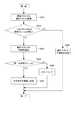
図5は、符号化対象のブロックと隣接するブロックを模式的に表した図である。図5において、符号化対象のブロックをEとし、ブロックAをブロックEの最も左上の画素の直左の画素を含むブロック、ブロックBをブロックEの最も左上の画素の直上の画素を含むブロック、ブロックCをブロックEの最も右上の画素の直右上の画素を含むブロックとする。また、ブロックDをブロックEの最も左上の画素の直左上の画素を含むブロックとする。
【0068】
まず、動きベクトル予測部204は、ブロックCが画面外である場合は、ブロックCの動きベクトルおよび参照フレーム番号は、ブロックDの動きベクトルおよび参照フレーム番号と同一であるとする。
【0069】
また、ブロックB、ブロックCがともに画面外である場合は、ブロックB、ブロックCの動きベクトルおよび参照フレーム番号は、ブロックAの動きベクトルおよび参照フレーム番号と同一であるとする。
【0070】
以上のような前提で、動きベクトル予測部204は、常に符号化対象のブロックEに隣接するブロックA、ブロックB、ブロックCの動きベクトル及び参照フレーム番号が存在するようにした上で、動きベクトル予測値の算出を行う。
【0071】
図6は、動きベクトル予測部204の動きベクトル予測値の算出時の動作を示すフローチャートである。
【0072】
まず、動きベクトル予測部204により、参照フレーム画像信号に含まれる符号化対象の所定ブロック(E)に隣接するブロック(A、B、C)の動きベクトルおよび参照フレーム画像番号が参照される(ステップS01)。
【0073】
次に、隣接ブロック(A、B、C)の参照フレーム画像番号のうち、どれか一つだけブロック(E)の参照フレーム画像番号と等しいかどうかが判定される(ステップS02)。隣接ブロック(A、B、C)の参照フレーム画像番号のうち、どれか一つだけブロック(E)の参照フレーム画像番号と等しい場合には(ステップS02:YES)、ブロック(E)の参照フレーム画像番号と等しい参照フレーム画像番号を持つブロックの動きベクトル値をブロック(E)の動きベクトル予測値と決定する(ステップS03)。隣接ブロック(A、B、C)の参照フレーム画像番号のうち、どれか一つだけブロック(E)の参照フレーム画像番号と等しい場合に該当しない時は(ステップS02:NO)、処理をステップS04に移行する。
【0074】
続いて、動きベクトル予測部204により、各隣接ブロック(A、B、C)が、ブロック(E)の動きベクトルを検出した参照フレーム画像番号と同一の参照フレーム画像を用いて動き補償されたものであるかが判定される(ステップS04)。検出した隣接ブロック(A、B、C)の参照フレーム画像が、ブロック(E)の動きベクトルを検出した参照フレーム画像と同一の参照フレーム画像でない場合(ステップS04:NO)、符号化対象のブロック(E)と同じ参照フレームの条件となるように隣接ブロック(A、B、C)の動きベクトル値がスケーリングされる(ステップS05)。
【0075】
このスケーリング方法を、図7に基づいて説明する。図7は、符号化対象のブロックと隣接するブロックの動きベクトルを時間空間上において示す図である。図7のように、現フレーム(対象フレーム画像)701(時刻t0)から、符号化対象のブロック(E)の参照フレーム(対象参照フレーム画像)702までの時間的距離(t0-te)を基準にして、検出した符号化対象の所定ブロックに隣接するブロック(A、B、C)の動きベクトル751a、751b、751cの大きさが変更される。具体的には、符号化対象のブロック(E)の参照フレーム702が時刻teにおけるもの、 隣接ブロックAの動きベクトル751aが(MVxA、MVyA)、その参照フレーム(隣接参照フレーム画像)703aが時刻taにおけるものであったとすると、符号化対象のブロック(E)の参照フレーム702を基準にスケーリングされた動きベクトル(MVxA’、 MVyA’)は、下記式(1)及び(2)によって求められる。
【0076】
【数1】
なお、この場合、隣接ブロック(A、B、C)は必ずしも過去の参照フレーム画像を用いて動き補償されている必要はなく、未来((t0-t)<0)の参照フレーム画像を用いて動き補償されていても良い。
【0078】
一方、図6に戻って、検出した隣接ブロック(A、B、C)の参照フレーム画像が、ブロック(E)の動きベクトルを検出した参照フレーム画像と同一の参照フレーム画像である場合(ステップS04:NO)、ブロック(A、B、C)の動きベクトル値をスケーリング済みとしてそのまま利用される(ステップS06)。
【0079】
次に、隣接ブロック(A、B、C)の動きベクトルが全て、スケーリング済みがどうかを判定する(ステップS07)。全ての隣接ブロック(A、B、C)がスケーリング済みでない場合には(ステップS07:NO)、ステップS04からの処理を繰り返す。
【0080】
全ての隣接ブロック(A、B、C)がスケーリング済みである場合には(ステップS07:YES)、符号化対象のブロック(E)の動きベクトルを検出した参照フレーム702を基準にしてスケーリングされた隣接ブロック(A、B、C)の動きベクトルの中間値を算出することにより、最適予測動きベクトルが決定される(ステップS08)。中間値の算出は、3つの隣接ブロック(A、B、C)のスケーリング後の動きベクトル(MVxA’、MVyA’)、(MVxB’、MVyB’)、(MVxC’、MVyC’)をx、y成分ごとに比較し、それぞれ成分の中でちょうど中間(2番目)の値が動きベクトル予測値とされる。例えば、(MVxA’、MVyA’)=(3、−5)、(MVxB’、MVyB’)=(−1、4)、(MVxC’、MVyC’)=(2、6)のとき、動きベクトル予測値(PMVxE、PMVyE)はx、y成分ごとの中間(2番目)の値である(2、4)となる。
【0081】
このよう隣接ブロックの動きベクトルの中間値を用いて符号化対象のブロックの動きベクトルを予測すると、符号化対象のブロックとその周囲のブロックとの空間的相関から、最適予測動きベクトルは符号化対象のブロックの実際の動きベクトルに比較的近い値になると考えられる。この方法は中間値予測(median prediction)と呼ばれている。
【0082】
次に、コンピュータを上述した動画像符号化装置10として機能させるための動画像符号化プログラム910と、コンピュータを上述した動画像復号化装置30として機能させるための動画像復号化プログラム930について説明する。図10、図11はそれぞれ、動画像符号化プログラム910、動画像復号化プログラム930の構成を示す図である。
【0083】
図10に示すように、動画像符号化プログラム910は、処理を統括するメインモジュール911と、入力モジュール912と、動き検出モジュール913と、動き補償モジュール914と、空間予測モジュール915と、スイッチモジュール916と、減算モジュール917と、直交変換モジュール918と、量子化モジュール919と、可変長符号化モジュール920と、逆量子化モジュール921と、逆直交変換モジュール922と、加算モジュール923とを備える。入力モジュール912、動き検出モジュール913、動き補償モジュール914、空間予測モジュール915、スイッチモジュール916、減算モジュール917、直交変換モジュール918、量子化モジュール919、可変長符号化モジュール920、逆量子化モジュール921、逆直交変換モジュール922、加算モジュール923がコンピュータに行わせる機能はそれぞれ、上述した入力部101、動き検出部102、動き補償部103、空間予測部105、スイッチ106、減算器107、直交変換部108、量子化部109、可変長符号化部110、逆量子化部111、逆直交変換部112、加算器113と同様である。
【0084】
また、図11に示すように、動画像復号化プログラム930は、処理を統括するメインモジュール931と、可変長復号化モジュール932と、動きベクトル復元モジュール933と、動き補償モジュール934と、空間予測モジュール935と、スイッチモジュール936と、逆量子化モジュール937と、逆直交変換モジュール938と、加算モジュール939とを備える。可変長復号化モジュール932、動きベクトル復元モジュール933、動き補償モジュール934、空間予測モジュール935、スイッチモジュール936、逆量子化モジュール937、逆直交変換モジュール938、加算モジュール939がコンピュータに実現させる機能はそれぞれ、上述した可変長復号化部301、動きベクトル復元部302、動き補償部303、空間予測部305、スイッチ306、逆量子化部307、逆直交変換部308、加算器309と同様である。
【0085】
以上述べた第1実施形態にかかる動画像符号化装置10及び動画像復号化装置30によれば、動きベクトル予測部204、401が、それぞれの隣接ブロックの動きベクトルを、対象ブロックの動きベクトルを検出するために参照されたフレーム画像と符号化対象のフレーム画像との時間差を基準としてスケーリングして補正した後に、補正された隣接ブロックの動きベクトルに基づいて最適予測動きベクトルを予測するので、時間的な動きの連続性を考慮して最適予測動きベクトルを決定することにより、実際の対象ブロックの動きベクトルと最適予測動きベクトルの差をより小さくすることができる。
【0086】
[第2実施形態]
次に、本発明の第2実施形態について説明する。本実施形態における動画像符号化装置及び動画像復号化装置の基本的構成は、第1実施形態における動画像符号化装置10及び動画像復号化装置30の構成と同様であるので、各構成要素には同一の符合を付しその説明は省略すると共に、以下において第1実施形態との相違点について詳述する。
【0087】
第2実施形態における動画像符号化装置及び動画像復号化装置と、第1実施形態における動画像符号化装置10及び動画像復号化装置30との相違点は、動きベクトル予測値の算出に関わる部分である。以下、第1実施形態と異なる動画像符号化装置10の動き検出部102および動画像復号化装置30の動きベクトル復元部302で行われる予想動きベクトルの算出について説明する。
【0088】
なお、動きベクトル予測部204による動きベクトル予測値の算出と、動きベクトル予測部401による動きベクトル予測値の算出は、同様の処理であるため、以下、動きベクトル予測部204の動作についてのみ説明する。
【0089】
本実施形態にかかる動きベクトル予測部204による動きベクトル予測値の算出においては、あらかじめ各隣接ブロックの動きベクトルを対象参照フレームを基準にしてスケーリングし、スケーリング後の動きベクトルに基づいて最適予測動きベクトルを決定することは行わない。つまり、動きベクトル予測部204は、まずスケーリング前の各隣接ブロックの動きベクトルに基づいて動きベクトルの予測に用いる最適なものを決定し、その後決定した動きベクトルの予測値を、対象参照フレームを基準にスケーリングして補正して動きベクトル予測値を得る。
【0090】
図8は、本実施形態にかかる動きベクトル予測部204の動きベクトル予測値の算出時の動作を示すフローチャートである。
【0091】
まず、動きベクトル予測部204により、参照フレーム画像信号に含まれる符号化対象の所定ブロック(E)に隣接するブロック(A、B、C)の動きベクトルおよび参照フレーム画像番号が参照される(ステップS201)。
【0092】
次に、隣接ブロック(A、B、C)の参照フレーム番号のうち、どれか一つだけがブロック(E)の参照フレーム番号と等しいかどうかが判定される(ステップS202)。隣接ブロック(A、B、C)の参照フレーム番号のうち、どれか一つだけがブロック(E)の参照フレーム番号と等しい場合(ステップS202:YES)、その等しい参照フレーム番号を有する隣接ブロックの動きベクトル値を、ブロック(E)の動きベクトル予測値と決定する(ステップS203)。隣接ブロック(A、B、C)の参照フレーム番号のうち、どれか一つだけがブロック(E)の参照フレーム番号と等しい場合に該当しない時は(ステップS202:NO)、処理をステップS204に移行する。
【0093】
続いて、動きベクトル予測部204により、各隣接ブロック(A、B、C)の動きベクトルに基づいて、符号化対象のブロック(E)の動きベクトルを検出した参照フレーム(対象参照フレーム画像)を基準にしてスケーリングを行うことなく、動きベクトル予測値として最適な動きベクトルが選出される(ステップS204)。動きベクトル予測値として最適な動きベクトルを選出する方法としては、実施形態1と同様にして、符号化対象のブロック(E)に隣接するブロック(A、B、C)の動きベクトルの中からx、y成分毎に中間の値を持つものを選出する。
【0094】
動きベクトルの選出後、符号化対象のブロック(E)の動きベクトル予測値に最適であるとしてx,y成分として選出されたそれぞれの動きベクトルが、ブロック(E)の動きベクトルを検出した参照フレーム画像番号と同一の参照フレーム画像を用いて動き補償されたものであるかが判定される(ステップS205)。選出されたそれぞれの動きベクトルが、符号化対象のブロック(E)の動きベクトルを検出した参照フレーム画像と同一の参照フレーム画像を用いて動き補償されたものでないとき(ステップS205:NO)、符号化対象のブロック(E)と同じ参照フレームの条件となるように動きベクトルのx,y成分の大きさをスケーリングする(ステップS206)。スケーリング方法としては、実施形態1と同様にして、現フレーム(対象フレーム画像)から符号化対象のブロックの参照フレーム(対象参照フレーム画像)までの時間的距離を基準にして、選出された隣接ブロックの動きベクトルの大きさを変更して、そのうちのx成分あるいはy成分を動きベクトル予測値とする。
【0095】
一方、選出されたそれぞれの動きベクトルが、符号化対象のブロック(E)の動きベクトルを検出した参照フレーム画像と同一の参照フレーム画像を用いて動き補償されたものであるとき(ステップS205:YES)、選出された動きベクトルのx成分あるいはy成分をそのまま動きベクトル予測値と決定する(ステップS207)。
【0096】
以上述べた第2実施形態にかかる動画像符号化装置10及び動画像復号化装置30によれば、動きベクトル予測部204、401が、隣接ブロックの動きベクトルに基づいて最適予測動きベクトルを決定した後、決定された最適予測動きベクトルを、対象ブロックの動きベクトルを検出するために参照されたフレーム画像と符号化対象のフレーム画像との時間差を基準としてスケーリングして補正するので、実際の対象領域の動きベクトルと最適予測動きベクトルの差をより小さくすることができると同時に、動きベクトルを予測するための処理時間を短縮することが可能となる。
【0097】
なお、上述した第1実施形態および第2実施形態にかかる動画像符号化装置10及び動画像復号化装置30においては、スケーリングする前、あるいはスケーリングした後の隣接するブロックの動きベクトルの中から中間値を選出して動きベクトル予測値として決定していたが、これは、以下のように動きベクトル予測値(PMVxE,PMVyE)を決定しても良い。
【0098】
すなわち、第1実施形態においては、スケーリング後のそれぞれの動きベクトルのx成分が条件1:|MVxA’−MVxB’|<|MVxB’−MVxC’|を満たす場合は、PMVxE=MVxA’と決定する。上記条件1を満たさない場合は、PMVxE=MVxB’と決定する。同様に、スケーリング後のそれぞれの動きベクトルのy成分が条件2:|MVyA’−MVyB’|<|MVyB’−MVyC’|を満たす場合は、PMVyE=MVyA’と決定する。上記条件2を満たさない場合は、PMVyE=MVyB’と決定する。また、実施形態2においては、スケーリング前のそれぞれの動きベクトルのx成分が条件1:|MVxA − MVxB|<|MVxB − MVxC|を満たす場合は、PMVxE=MVxAと決定する。上記条件1を満たさない場合は、PMVxE=MVxBと決定する。同様に、スケーリング前のそれぞれの動きベクトルのy成分が条件2:|MVyA − MVyB|<|MVyB − MVyC|を満たす場合は、PMVyE=MVyAと決定する。上記条件2を満たさない場合は、PMVyE=MVyBと決定する。その後、決定された動きベクトル予測値をスケーリングする。
【0099】
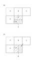
さらに、以下のような方法で動きベクトル予測値を決定しても良い。すなわち、符号化対象の所定ブロックの分割方法などに応じて、動きベクトルの予測値に用いるブロックの位置を一意に決定しておき、そのブロックの動きベクトルを常に選出するようにしても良い。図9は、動きベクトルの予測のために分割されたブロックの一例を示す図である。図9(a)に例によれば、符号化対象のブロックEが16画素x8画素の2つの領域に分割される予測モードの場合、上側の領域はブロックBの動きベクトルを、下側の領域はブロックAの動きベクトルを、それぞれ動きベクトル予測値として決定する。また、図9(b)の例によれば、ブロックEが8画素x16画素の2つの領域に分割される予測モードの場合、左側の領域はブロックAの動きベクトルを、右側の領域はブロックCの動きベクトルを、それぞれ動きベクトルの予測値として決定する。なお、上記の各予測モードによって分割された領域に対して選出される動きベクトルの位置は一例であって、任意の位置の動きベクトルを符号化対象のブロックの動きベクトル予測値として決定することができる。
【0100】
また、上述した第1実施形態および第2実施形態にかかる動画像符号化装置10及び動画像復号化装置30においては、図5に示すように、符号化対象のブロック(E)の動きベクトル予測値を決定するために、隣接ブロック(A、B、C)の動きベクトルを利用していたが、この隣接ブロックの数及びブロック(E)との相対的位置は、適宜変更しても良い。
【0101】
【発明の効果】
本発明の動画像符号化装置及び動画像復号化装置によれば、動きベクトル予測手段が、隣接領域の動きベクトルを対象領域の動きベクトルを検出するために参照されたフレーム画像と符号化対象のフレーム画像との時間差を基準としてスケーリングして補正するとともに、隣接領域の動きベクトルに基づいて最適予測動きベクトルを予測するので、時間的な動きの連続性を考慮して予測動きベクトルを決定することにより、実際の対象領域の動きベクトルと予測動きベクトルの差をより小さくすることができる。これにより、符号化及び復号化の情報圧縮の効率の向上を図ることが可能な動画像符号化装置、動画像復号化装置を提供することができる。
【図面の簡単な説明】
【図1】本実施形態にかかる動画像符号化装置の一例を示す概略図である。
【図2】図1に示す動き検出部の構成図である。
【図3】本実施形態にかかる動画像復号化装置の一例を示す概略図である。
【図4】図3に示す動きベクトル復元部の構成図である。
【図5】符号化対象のブロックと隣接するブロックを模式的に表した図である。
【図6】第1実施形態における動きベクトル予測部の動作を示すフローチャートである。
【図7】符号化対象のブロックと隣接するブロックの動きベクトルを時間空間上において示す図である。
【図8】第2実施形態における動きベクトル予測部の動作を示すフローチャートである。
【図9】(a)は、動きベクトルの予測のために分割されたブロックの一例を示す図、(b)は、動きベクトルの予測のために分割されたブロックの他の例を示す図である。
【図10】本実施形態にかかる動画像符号化プログラムの構成を示す図である。
【図11】本実施形態にかかる動画像復号化プログラムの構成を示す図である。
【符号の説明】
10…動画像符号化装置、30…動画像復号化装置、101…入力部、102…動き検出部、103…動き補償部、104…フレームメモリ、105…空間予測部、106…スイッチ、107…減算器、108…直交変換部、109…量子化部、110…可変長符号化部、111…逆量子化部、112…逆直交変換部、113…加算器、201…予測モード決定部、202…参照フレーム決定部、203…動きベクトル検出部、204…動きベクトル予測部(動きベクトル予測手段)、205…動きベクトル差分部、301…可変長復号化部、302…動きベクトル復元部、303…動き補償部、304…フレームメモリ、305…空間予測部、306…スイッチ、307…逆量子化部、308…逆直交変換部、309…加算器、401…動きベクトル予測部(動きベクトル予測手段)、402…動きベクトル加算部、701…対象フレーム画像、702…対象参照フレーム画像、703a、703b、703c…隣接参照フレーム画像、751a、751c、751c…動きベクトル。[0001]
BACKGROUND OF THE INVENTION
The present invention relates to a moving image encoding device, a moving image decoding device, a moving image encoding method, a moving image decoding method, a moving image encoding program, and a moving image decoding program.
[0002]
[Prior art]
As an example of a conventional moving image encoding method, H.264 has been described. Examples thereof include a moving image encoding device and a moving image decoding device based on the H.264 / AVC encoding method (see Non-Patent Document 1). This method reduces the redundancy existing in the temporal direction by motion compensation inter-frame prediction, and further reduces the redundancy remaining in the spatial direction by orthogonal transformation, thereby compressing information of the moving image (input video signal). It is.
[0003]
In motion compensation inter-frame prediction (hereinafter referred to as “INTER prediction mode”) in the above method, a plurality of reference frame images for detecting a motion vector can be prepared. The motion vectors may be motion compensated using different reference frame images.
[0004]
In addition, when calculating the prediction motion vector of the encoding target region, regardless of which reference frame image the motion vector of the surrounding encoded region has been motion compensated, the values of those motion vectors are compared, These intermediate values are used as motion vector prediction values for the region to be encoded.
[0005]
[Non-Patent Document 1]
Joint Video Team (JVT) of ISO / IEC MPEG and ITU-VCEG, "Editor's Proposed Draft Text Modifications for Joint Video Specification (ITU-T Rec.H.264 | ISO / IEC 14496-10 AVC), Geneva modifications draft 37"
[0006]
[Problems to be solved by the invention]
However, when the surrounding encoded region is motion-compensated using a reference frame image different from the reference frame image of the encoding target region as described above, the difference between the reference frames is obtained by using the intermediate value as a predicted motion vector. Therefore, there is a problem that the efficiency of encoding information compression is reduced due to a large deviation from the actual motion vector. Along with this, there is a problem that the efficiency of information compression for decoding also decreases at the same time.
[0007]
The present invention has been made to solve the above-described problem, and is a moving image encoding device, a moving image decoding device, and a moving image capable of improving the efficiency of encoding and decoding information compression. It is an object to provide an encoding method, a moving image decoding method, a moving image encoding program, and a moving image decoding program.
[0008]
[Means for Solving the Problems]
The moving image encoding apparatus according to the present invention divides a frame image to be encoded in a moving image signal composed of a time sequence of frame image signals into a plurality of target regions, and the frame image to be encoded for each target region. By detecting a motion vector with reference to a plurality of different frame images, a motion image encoding apparatus that performs motion compensation encoding is used to determine an optimal prediction motion vector based on a motion vector of an adjacent region adjacent to the target region. The adjacent reference frame image of the motion vector of the adjacent region determined and determined as the optimal prediction motion vector, the target reference frame image referred to for detecting the motion vector of the target region, and the frame image to be encoded Based on the temporal relationship with the target frame image or their time information, the optimal prediction motion based on the target reference frame image A motion vector prediction means for correcting scales the vector,Means for obtaining information that is a value calculated from the motion vector between the target frame image and the target reference frame image and the optimum predicted motion vector corrected by the motion vector prediction means, and that is encoded and transmitted as a compressed stream;It is characterized by having.
[0009]
The moving image encoding method of the present invention divides a frame image to be encoded in a moving image signal composed of a time sequence of frame image signals into a plurality of target regions, and for each target region, In a moving image coding method for performing motion compensation coding by detecting a motion vector with reference to a plurality of frame images different from a frame image, the motion vector predicting means includes a motion vector of an adjacent region adjacent to the target region. Determining an optimal prediction motion vector based on: an adjacent reference frame image of a motion vector of an adjacent region determined as the optimal prediction motion vector; and a target reference frame image referred to detect a motion vector of the target region And the temporal relationship between the frame image to be encoded and the target frame image or the time information thereof, Step of correcting by scaling the optimum prediction motion vector based on the elephant reference frame pictureAnd obtaining information encoded and transmitted as a compressed stream, which is a value calculated from the motion vector between the target frame image and the target reference frame image and the corrected optimal prediction motion vector.It is characterized by having.
[0010]
Further, the moving image encoding program of the present invention divides a frame image to be encoded in a moving image signal composed of a time sequence of frame image signals into a plurality of target regions, and for each target region, In a moving image encoding program that causes a computer to execute an encoding process based on motion compensation by detecting a motion vector with reference to a plurality of frame images different from the frame image, the computer moves the motion of the adjacent region adjacent to the target region. An optimal prediction motion vector is determined based on the vector, an adjacent reference frame image of the motion vector of the adjacent region determined as the optimal prediction motion vector, and a target reference frame image referred to for detecting the motion vector of the target region, , Temporal relationship with the target frame image that is the frame image to be encoded, or their time Based on the distribution, the motion vector prediction means for correcting scaling the optimum prediction motion vector based on the target reference frame image,Means for calculating information transmitted as a compressed stream, which is a value calculated from a motion vector between the target frame image and the target reference frame image and an optimal prediction motion vector corrected by the motion vector prediction means;It is made to function as.
[0011]
According to the moving image encoding apparatus, the moving image encoding method, and the moving image encoding program of the present invention, the motion vector prediction means includes:After determining the optimal prediction motion vector based on the motion vector of the adjacent region, the determined optimal prediction motion vector is obtained by using the frame image referred to for detecting the motion vector of the target region and the frame image to be encoded. Since the time difference is scaled and corrected, the difference between the motion vector of the actual target region and the predicted motion vector can be further reduced, and the processing time for predicting the motion vector can be shortened. .
[0014]
The moving picture decoding apparatus of the present invention divides a frame image to be decoded in a moving picture signal composed of a time sequence of frame image signals into a plurality of target areas, In a video decoding device that performs decoding by motion compensation by using difference information between a motion vector detected with reference to a plurality of different frame images and a predicted motion vector, an adjacent region adjacent to the target region The optimal prediction motion vector is determined based on the motion vector, the adjacent reference frame image of the motion vector of the adjacent region determined as the optimal prediction motion vector, and the target reference frame image referred to detect the motion vector of the target region And the time relationship between the frame image to be encoded and the target frame image or the time information thereof, Motion vector prediction means for correcting scaling the optimum prediction motion vector based on the irradiation frame imageAnd a motion vector obtained by performing an operation using the optimal predicted motion vector corrected by the motion vector prediction means on a value calculated from the motion vector and the predicted motion vector between the target frame image and the target reference frame image. With the means to restoreIt is characterized by having.
[0015]
Also, the moving picture decoding method of the present invention divides a decoding target frame image in a moving picture signal composed of a time sequence of frame image signals into a plurality of target areas, and the decoding target frames for each target area. In a moving picture decoding method for performing decoding by motion compensation by using difference information between a motion vector detected with reference to a plurality of frame images different from an image and a predicted motion vector, the motion vector prediction means includes: A step of determining an optimal prediction motion vector based on a motion vector of an adjacent region adjacent to the target region, an adjacent reference frame image of the motion vector of the adjacent region determined as the optimal prediction motion vector, and a motion vector of the target region are detected Between the target reference frame image referred to for encoding and the target frame image that is the frame image to be encoded Based on the relationship or their time information is corrected by scaling the optimum prediction motion vector based on the target reference frame image stepAnd restoring the motion vector by performing an operation using the corrected optimal predicted motion vector on a value calculated from the motion vector and the predicted motion vector between the target frame image and the target reference frame image;It is characterized by having.
[0016]
Further, the moving picture decoding program of the present invention divides a decoding target frame image in a moving picture signal composed of a time sequence of frame image signals into a plurality of target areas, and the decoding target frame for each target area. In a moving image decoding program for causing a computer to execute a decoding process by motion compensation by using difference information between a motion vector detected with reference to a plurality of frame images different from the image and a predicted motion vector, the computer The optimal prediction motion vector is determined based on the motion vector of the adjacent region adjacent to the target region, and the adjacent reference frame image of the motion vector of the adjacent region determined as the optimal prediction motion vector and the motion vector of the target region are detected. A target reference frame image referred to for encoding and a target frame that is a frame image to be encoded. Based on the temporal relationship or their time information and image, the motion vector prediction means for correcting scaling the optimum prediction motion vector based on the target reference frame image,The motion vector is restored by performing an operation using the optimum predicted motion vector corrected by the motion vector prediction means on the value calculated from the motion vector and the predicted motion vector between the target frame image and the target reference frame image. Means to doIt is made to function as.
[0017]
According to the moving picture decoding apparatus, the moving picture decoding method, and the moving picture decoding program of the present invention, the motion vector prediction means includes:After determining the optimal prediction motion vector based on the motion vector of the adjacent region, the determined optimal prediction motion vector is obtained by using the frame image referred to for detecting the motion vector of the target region and the frame image to be encoded. Since the time difference is scaled and corrected, the difference between the motion vector of the actual target region and the predicted motion vector can be further reduced, and the processing time for predicting the motion vector can be shortened. .
[0020]
DETAILED DESCRIPTION OF THE INVENTION
A video encoding device and a video decoding device according to an embodiment of the present invention will be described with reference to the drawings. In addition, in each figure, the same code | symbol is attached | subjected to the same element and the overlapping description is abbreviate | omitted.
[0021]
[First Embodiment]
FIG. 1 is a schematic diagram illustrating an example of a video encoding device according to the present embodiment, and FIG. 3 is a schematic diagram illustrating an example of a video decoding device according to the present embodiment.
[0022]
(Configuration of video encoding device)
First, a moving
[0023]
Here, an input video signal (moving image signal) as a moving image signal input to the moving
[0024]
H. In the H.264 / AVC encoding method, a motion vector is detected for each macroblock with reference to a plurality of encoded frame image signals (reference frame image signals) that are temporally different from the frame image signal as a prediction mode. A plurality of “INTER prediction modes” for performing motion compensation inter-frame prediction and a plurality of “INTRA prediction modes” for performing spatial prediction using pixel values of neighboring macroblocks that have been encoded in the same space are prepared. Has been. In the “INTER prediction mode”, motion detection, motion prediction, and motion compensation processes (details) are performed for each block (target region) obtained by further dividing the macroblock into arbitrary regions (for example, 8 pixels × 16 lines). Will be described later). The moving
[0025]
As shown in FIG. 1, the moving
[0026]
The
[0027]
The frame memory 104 is a part for storing previously encoded frame image signals.
[0028]
The
[0029]
Also, the
[0030]
On the other hand, when the “INTRA prediction mode” is selected, the
[0031]
On the other hand, the
[0032]
The
[0033]
On the other hand, the
[0034]
The
[0035]
On the other hand, the
[0036]
Next, the variable
[0037]
In addition, the inverse quantization unit 111 generates an
[0038]
Then, the inverse orthogonal transform unit 112 performs an inverse orthogonal transform on the
[0039]
The
[0040]
Next, the
[0041]
As shown in FIG. 2, the
[0042]
First, the prediction
[0043]
The reference
[0044]
Based on the input frame image signal, reference frame image signal, prediction mode, and reference frame number, the motion
[0045]
The motion
[0046]
The motion vector difference unit 205 calculates a motion vector difference value that is a value obtained by subtracting a motion vector prediction value from the input motion vector, and performs a variable length encoding prediction mode, a reference frame number, and a motion vector difference value. A
[0047]
(Configuration of video decoding device)
Next, the moving
[0048]
The moving
[0049]
As shown in FIG. 1, the moving
[0050]
After receiving the
[0051]
When the prediction mode is “INTER prediction mode”, the motion
[0052]
Next, the
[0053]
In addition, when the
[0054]
Next, the
[0055]
On the other hand, the
[0056]
The inverse
[0057]
Then, the
[0058]
Finally, the
[0059]
The
[0060]
Next, the motion
[0061]
First, the motion
[0062]
The motion vector addition unit 402 restores a motion vector based on the input motion vector prediction value, prediction mode, motion vector difference value, and reference frame number. Then, a
[0063]
(Calculation of optimal prediction motion vector)
Here, the calculation of the optimal prediction motion vector performed in the
[0064]
The motion
[0065]
In addition, the motion
[0066]
Since the calculation of the motion vector prediction value by the motion
[0067]
FIG. 5 is a diagram schematically showing a block adjacent to a block to be encoded. In FIG. 5, the block to be encoded is E, block A is a block including the pixel immediately left of the upper leftmost pixel of block E, block B is a block including the pixel immediately above the upper leftmost pixel of block E, The block C is a block including the pixel immediately above the upper right pixel of the block E. Further, the block D is a block including the pixel immediately above the leftmost pixel of the block E.
[0068]
First, when the block C is outside the screen, the motion
[0069]
When both block B and block C are outside the screen, the motion vector and reference frame number of block B and block C are the same as the motion vector and reference frame number of block A.
[0070]
On the premise as described above, the motion
[0071]
FIG. 6 is a flowchart showing the operation of the motion
[0072]
First, the motion
[0073]
Next, it is determined whether only one of the reference frame image numbers of the adjacent blocks (A, B, C) is equal to the reference frame image number of the block (E) (step S02). If any one of the reference frame image numbers of the adjacent blocks (A, B, C) is equal to the reference frame image number of the block (E) (step S02: YES), the reference frame of the block (E) The motion vector value of the block having the reference frame image number equal to the image number is determined as the motion vector prediction value of the block (E) (step S03). If it is not the case that any one of the reference frame image numbers of the adjacent blocks (A, B, C) is equal to the reference frame image number of the block (E) (step S02: NO), the process is performed in step S04. Migrate to
[0074]
Subsequently, the motion
[0075]
This scaling method will be described with reference to FIG. FIG. 7 is a diagram illustrating a motion vector of a block adjacent to the encoding target block in time space. As shown in FIG. 7, the temporal distance (t0-te) from the current frame (target frame image) 701 (time t0) to the reference frame (target reference frame image) 702 of the encoding target block (E) is used as a reference. Thus, the magnitudes of the
[0076]
[Expression 1]
In this case, the adjacent blocks (A, B, C) are not necessarily motion-compensated using the past reference frame image, and the future ((t0−t) <0) reference frame image is used. Motion compensation may be performed.
[0078]
On the other hand, referring back to FIG. 6, when the detected reference frame image of the adjacent block (A, B, C) is the same reference frame image as the reference frame image from which the motion vector of the block (E) is detected (step S04). : NO), the motion vector values of the blocks (A, B, C) are used as they are after being scaled (step S06).
[0079]
Next, it is determined whether all the motion vectors of the adjacent blocks (A, B, C) have been scaled (step S07). If all adjacent blocks (A, B, C) have not been scaled (step S07: NO), the processing from step S04 is repeated.
[0080]
When all the adjacent blocks (A, B, C) have been scaled (step S07: YES), they have been scaled based on the
[0081]
When the motion vector of the encoding target block is predicted using the intermediate value of the motion vector of the adjacent block as described above, the optimal prediction motion vector is determined from the spatial correlation between the encoding target block and the surrounding blocks. It is considered that the value is relatively close to the actual motion vector of the block. This method is called median prediction.
[0082]
Next, a
[0083]
As illustrated in FIG. 10, the moving
[0084]
As shown in FIG. 11, the moving
[0085]
According to the
[0086]
[Second Embodiment]
Next, a second embodiment of the present invention will be described. The basic configurations of the moving image encoding device and the moving image decoding device in the present embodiment are the same as the configurations of the moving
[0087]
The difference between the video encoding device and video decoding device in the second embodiment and the
[0088]
Since the calculation of the motion vector prediction value by the motion
[0089]
In the calculation of the motion vector prediction value by the motion
[0090]
FIG. 8 is a flowchart showing an operation at the time of calculating a motion vector prediction value of the motion
[0091]
First, the motion
[0092]
Next, it is determined whether only one of the reference frame numbers of the adjacent blocks (A, B, C) is equal to the reference frame number of the block (E) (step S202). When only one of the reference frame numbers of the adjacent blocks (A, B, C) is equal to the reference frame number of the block (E) (step S202: YES), the adjacent block having the same reference frame number is selected. The motion vector value is determined as the motion vector prediction value of the block (E) (step S203). If only one of the reference frame numbers of the adjacent blocks (A, B, C) is equal to the reference frame number of the block (E) (step S202: NO), the process goes to step S204. Transition.
[0093]
Subsequently, the reference frame (target reference frame image) in which the motion vector of the encoding target block (E) is detected by the motion
[0094]
After the motion vector is selected, the reference frame in which each motion vector selected as the x and y component as the optimum motion vector prediction value of the encoding target block (E) detects the motion vector of the block (E). It is determined whether motion compensation has been performed using the same reference frame image as the image number (step S205). When each selected motion vector is not motion-compensated using the same reference frame image as the reference frame image in which the motion vector of the encoding target block (E) is detected (step S205: NO), The size of the x and y components of the motion vector is scaled so as to satisfy the same reference frame conditions as the block (E) to be converted (step S206). As a scaling method, similar to the first embodiment, the adjacent blocks selected based on the temporal distance from the current frame (target frame image) to the reference frame (target reference frame image) of the block to be encoded , And the x component or y component is used as a motion vector prediction value.
[0095]
On the other hand, when each selected motion vector is motion-compensated using the same reference frame image as the reference frame image in which the motion vector of the encoding target block (E) is detected (step S205: YES) ), The x component or y component of the selected motion vector is determined as the motion vector prediction value as it is (step S207).
[0096]
According to the
[0097]
In addition, in the moving
[0098]
That is, in the first embodiment, when the x component of each scaled motion vector satisfies the condition 1: | MVxA′−MVxB ′ | <| MVxB′−MVxC ′ |, PMVxE = MVxA ′ is determined. . When the above condition 1 is not satisfied, PMVxE = MVxB ′ is determined. Similarly, when the y component of each scaled motion vector satisfies the condition 2: | MVyA′−MVyB ′ | <| MVyB′−MVyC ′ |, PMVyE = MVyA ′ is determined. When the above condition 2 is not satisfied, PMVyE = MVyB ′ is determined. In the second embodiment, when the x component of each motion vector before scaling satisfies the condition 1: | MVxA−MVxB | <| MVxB−MVxC |, PMVxE = MVxA is determined. When the above condition 1 is not satisfied, PMVxE = MVxB is determined. Similarly, when the y component of each motion vector before scaling satisfies the condition 2: | MVyA−MVyB | <| MVyB−MVyC |, PMVyE = MVyA is determined. When the above condition 2 is not satisfied, PMVyE = MVyB is determined. Thereafter, the determined motion vector prediction value is scaled.
[0099]
Further, the motion vector prediction value may be determined by the following method. That is, the position of a block used as a motion vector prediction value may be uniquely determined according to the method for dividing a predetermined block to be encoded, and the motion vector of that block may be always selected. FIG. 9 is a diagram illustrating an example of blocks divided for motion vector prediction. According to the example in FIG. 9A, in the prediction mode in which the block E to be encoded is divided into two areas of 16 pixels × 8 pixels, the upper area represents the motion vector of the block B and the lower area. Determines the motion vector of block A as a motion vector prediction value. Further, according to the example of FIG. 9B, in the prediction mode in which the block E is divided into two regions of 8 pixels × 16 pixels, the left region is the motion vector of the block A, and the right region is the block C. Are determined as predicted motion vectors. Note that the position of the motion vector selected for the region divided by each prediction mode is an example, and the motion vector at an arbitrary position can be determined as the motion vector prediction value of the block to be encoded. it can.
[0100]
Further, in the moving
[0101]
【The invention's effect】
According to the moving image encoding device and the moving image decoding device of the present invention, the motion vector predicting means includes the frame image referred to for detecting the motion vector of the target region as the motion vector of the adjacent region and the encoding target. Scaling and correcting based on the time difference from the frame image and predicting the optimal predicted motion vector based on the motion vector of the adjacent region, so determine the predicted motion vector in consideration of temporal motion continuity Thus, the difference between the motion vector of the actual target region and the predicted motion vector can be further reduced. Accordingly, it is possible to provide a moving image encoding device and a moving image decoding device that can improve the efficiency of encoding and decoding information compression.
[Brief description of the drawings]
FIG. 1 is a schematic diagram illustrating an example of a moving image encoding apparatus according to an embodiment.
2 is a configuration diagram of a motion detection unit shown in FIG.
FIG. 3 is a schematic diagram illustrating an example of a moving picture decoding apparatus according to the present embodiment.
4 is a configuration diagram of a motion vector restoration unit shown in FIG. 3. FIG.
FIG. 5 is a diagram schematically showing a block adjacent to a block to be encoded.
FIG. 6 is a flowchart showing an operation of a motion vector prediction unit in the first embodiment.
FIG. 7 is a diagram illustrating a motion vector of a block adjacent to an encoding target block in time space.
FIG. 8 is a flowchart showing an operation of a motion vector prediction unit in the second embodiment.
FIG. 9A is a diagram illustrating an example of blocks divided for motion vector prediction, and FIG. 9B is a diagram illustrating another example of blocks divided for motion vector prediction; is there.
FIG. 10 is a diagram showing a configuration of a moving image encoding program according to the present embodiment.
FIG. 11 is a diagram showing a configuration of a moving picture decoding program according to the present embodiment.
[Explanation of symbols]
DESCRIPTION OF
Claims (6)
Translated fromJapanese前記対象領域に隣接する隣接領域の動きベクトルに基づいて最適予測動きベクトルを決定し、
前記最適予測動きベクトルとして決定された隣接領域の動きベクトルの隣接参照フレーム画像と、前記対象領域の動きベクトルを検出するために参照された対象参照フレーム画像と、前記符号化対象のフレーム画像である対象フレーム画像との時間的な関係又はそれらの時刻情報に基づいて、前記対象参照フレーム画像を基準にして前記最適予測動きベクトルをスケーリングして補正する動きベクトル予測手段と、
前記対象フレーム画像及び前記対象参照フレーム画像間の動きベクトルと、前記動きベクトル予測手段により補正された前記最適予測動きベクトルとから算出された値であり、符号化され圧縮ストリームとして伝送される情報を求める手段と
を有することを特徴とする動画像符号化装置。A frame image to be encoded in a moving image signal composed of a time sequence of frame image signals is divided into a plurality of target regions, and a plurality of frame images different from the frame image to be encoded are referenced for each target region. In the moving picture coding apparatus that performs coding by motion compensation by detecting a motion vector,
Determining an optimal prediction motion vector based on a motion vector of an adjacent region adjacent to the target region;
The adjacent reference frame image of the motion vector of the adjacent region determined as the optimal prediction motion vector, the target reference frame image referred to for detecting the motion vector of the target region, and the frame image to be encoded Motion vector prediction means for scaling and correcting the optimum predicted motion vector based on the target reference frame image based on a temporal relationship with the target frame image or time information thereof;
Information that is a value calculated from the motion vector between the target frame image and the target reference frame image and the optimal prediction motion vector corrected by the motion vector prediction means, and is encoded and transmitted as a compressed stream. And a means for obtaining the moving image coding apparatus.
前記対象領域に隣接する隣接領域の動きベクトルに基づいて最適予測動きベクトルを決定し、
前記最適予測動きベクトルとして決定された隣接領域の動きベクトルの隣接参照フレーム画像と、前記対象領域の動きベクトルを検出するために参照された対象参照フレーム画像と、前記符号化対象のフレーム画像である対象フレーム画像との時間的な関係又はそれらの時刻情報に基づいて、前記対象参照フレーム画像を基準にして前記最適予測動きベクトルをスケーリングして補正する動きベクトル予測手段と、
前記対象フレーム画像及び前記対象参照フレーム画像間の動きベクトルと前記予測動きベクトルとから算出された値に対して、前記動きベクトル予測手段により補正された前記最適予測動きベクトルを用いた演算を行うことにより動きベクトルを復元する手段と
を有することを特徴とする動画像復号化装置。A frame image to be decoded in a moving image signal composed of a time sequence of frame image signals is divided into a plurality of target regions, and a plurality of frame images different from the frame images to be decoded are referred to for each target region. In the moving picture decoding apparatus that performs decoding by motion compensation by using the difference information between the detected motion vector and the predicted motion vector,
Determining an optimal prediction motion vector based on a motion vector of an adjacent region adjacent to the target region;
The adjacent reference frame image of the motion vector of the adjacent region determined as the optimal prediction motion vector, the target reference frame image referred to for detecting the motion vector of the target region, and the frame image to be encoded Motion vector prediction means for scaling and correcting the optimum predicted motion vector based on the target reference frame image based on a temporal relationship with the target frame image or time information thereof;
Performing an operation using the optimum predicted motion vector corrected by the motion vector predicting unit on a value calculated from a motion vector between the target frame image and the target reference frame image and the predicted motion vector. A moving picture decoding apparatus comprising:means for reconstructing a motion vector .
動きベクトル予測手段が、
前記対象領域に隣接する隣接領域の動きベクトルに基づいて最適予測動きベクトルを決定するステップと、
前記最適予測動きベクトルとして決定された隣接領域の動きベクトルの隣接参照フレーム画像と、前記対象領域の動きベクトルを検出するために参照された対象参照フレーム画像と、前記符号化対象のフレーム画像である対象フレーム画像との時間的な関係又はそれらの時刻情報に基づいて、前記対象参照フレーム画像を基準にして前記最適予測動きベクトルをスケーリングして補正するステップと、
前記対象フレーム画像及び前記対象参照フレーム画像間の動きベクトルと、補正された前記最適予測動きベクトルとから算出された値であり、符号化され圧縮ストリームとして伝送される情報を求めるステップと
を有することを特徴とする動画像符号化方法。A frame image to be encoded in a moving image signal composed of a time sequence of frame image signals is divided into a plurality of target regions, and a plurality of frame images different from the frame image to be encoded are referred to for each target region. In the moving picture coding method for performing the motion compensation coding by detecting the motion vector,
The motion vector prediction means
Determining an optimal predicted motion vector based on a motion vector of an adjacent region adjacent to the target region;
The adjacent reference frame image of the motion vector of the adjacent region determined as the optimal prediction motion vector, the target reference frame image referred to for detecting the motion vector of the target region, and the frame image to be encoded Scaling and correcting the optimum predicted motion vector based on the target reference frame image based on a temporal relationship with the target frame image or time information thereof; and
Obtaining information that is a value calculated from the motion vector between the target frame image and the target reference frame image and the corrected optimal prediction motion vector, and that is encoded and transmitted as a compressed stream. A video encoding method characterized by the above.
動きベクトル予測手段が、
前記対象領域に隣接する隣接領域の動きベクトルに基づいて最適予測動きベクトルを決定するステップと、
前記最適予測動きベクトルとして決定された隣接領域の動きベクトルの隣接参照フレーム画像と、前記対象領域の動きベクトルを検出するために参照された対象参照フレーム画像と、前記符号化対象のフレーム画像である対象フレーム画像との時間的な関係又はそれらの時刻情報に基づいて、前記対象参照フレーム画像を基準にして前記最適予測動きベクトルをスケーリングして補正するステップと、
前記対象フレーム画像及び前記対象参照フレーム画像間の動きベクトルと前記予測動きベクトルとから算出された値に対して、補正された前記最適予測動きベクトルを用いた演算を行うことにより動きベクトルを復元するステップと
を有することを特徴とする動画像復号化方法。A frame image to be decoded in a moving image signal composed of a time sequence of frame image signals is divided into a plurality of target regions, and a plurality of frame images different from the frame images to be decoded are referred to for each target region. In the moving picture decoding method for performing decoding by motion compensation by using difference information between the motion vector detected in this way and the predicted motion vector,
The motion vector prediction means
Determining an optimal predicted motion vector based on a motion vector of an adjacent region adjacent to the target region;
The adjacent reference frame image of the motion vector of the adjacent region determined as the optimal prediction motion vector, the target reference frame image referred to for detecting the motion vector of the target region, and the frame image to be encoded Scaling and correcting the optimum predicted motion vector based on the target reference frame image based on a temporal relationship with the target frame image or time information thereof; and
A motion vector is restored by performing an operation using the corrected optimal predicted motion vector on a value calculated from the motion vector between the target frame image and the target reference frame image and the predicted motion vector. A moving picture decoding method comprising:steps .
コンピュータを、
前記対象領域に隣接する隣接領域の動きベクトルに基づいて最適予測動きベクトルを決定し、
前記最適予測動きベクトルとして決定された隣接領域の動きベクトルの隣接参照フレーム画像と、前記対象領域の動きベクトルを検出するために参照された対象参照フレーム画像と、前記符号化対象のフレーム画像である対象フレーム画像との時間的な関係又はそれらの時刻情報に基づいて、前記対象参照フレーム画像を基準にして前記最適予測動きベクトルをスケーリングして補正する動きベクトル予測手段、
前記対象フレーム画像及び前記対象参照フレーム画像間の動きベクトルと、前記動きベクトル予測手段により補正された前記最適予測動きベクトルとから算出された値であり、符号化され圧縮ストリームとして伝送される情報を求める手段、
として機能させることを特徴とする動画像符号化プログラム。A frame image to be encoded in a moving image signal composed of a time sequence of frame image signals is divided into a plurality of target regions, and a plurality of frame images different from the frame image to be encoded are referenced for each target region. In the moving picture encoding program for causing the computer to execute the encoding process by motion compensation by detecting the motion vector
Computer
Determining an optimal prediction motion vector based on a motion vector of an adjacent region adjacent to the target region;
The adjacent reference frame image of the motion vector of the adjacent region determined as the optimal prediction motion vector, the target reference frame image referred to for detecting the motion vector of the target region, and the frame image to be encoded A motion vector prediction unit that scales and corrects the optimal prediction motion vector based on the target reference frame image based on a temporal relationship with the target frame image or time information thereof;
Information that is a value calculated from the motion vector between the target frame image and the target reference frame image and the optimal prediction motion vector corrected by the motion vector prediction means, and is encoded and transmitted as a compressed stream. Means to seek,
A video encoding program characterized by being made to function as:
コンピュータを、
前記対象領域に隣接する隣接領域の動きベクトルに基づいて最適予測動きベクトルを決定し、
前記最適予測動きベクトルとして決定された隣接領域の動きベクトルの隣接参照フレーム画像と、前記対象領域の動きベクトルを検出するために参照された対象参照フレーム画像と、前記符号化対象のフレーム画像である対象フレーム画像との時間的な関係又はそれらの時刻情報に基づいて、前記対象参照フレーム画像を基準にして前記最適予測動きベクトルをスケーリングして補正する動きベクトル予測手段、
前記対象フレーム画像及び前記対象参照フレーム画像間の動きベクトルと前記予測動きベクトルとから算出された値に対して、前記動きベクトル予測手段により補正された前記最適予測動きベクトルを用いた演算を行うことにより動きベクトルを復元する手段、
として機能させることを特徴とする動画像復号化プログラム。A frame image to be decoded in a moving image signal composed of a time sequence of frame image signals is divided into a plurality of target regions, and a plurality of frame images different from the frame images to be decoded are referred to for each target region. In a moving picture decoding program for causing a computer to execute a decoding process by motion compensation by using difference information between a detected motion vector and a predicted motion vector,
Computer
Determining an optimal prediction motion vector based on a motion vector of an adjacent region adjacent to the target region;
The adjacent reference frame image of the motion vector of the adjacent region determined as the optimal prediction motion vector, the target reference frame image referred to for detecting the motion vector of the target region, and the frame image to be encoded A motion vector prediction unit that scales and corrects the optimal prediction motion vector based on the target reference frame image based on a temporal relationship with the target frame image or time information thereof;
Performing an operation using the optimum predicted motion vector corrected by the motion vector predicting unit on a value calculated from a motion vector between the target frame image and the target reference frame image and the predicted motion vector. Means for restoring motion vectors by
A moving picture decoding program characterized by being made to function as:
Priority Applications (9)
| Application Number | Priority Date | Filing Date | Title |
|---|---|---|---|
| JP2003129333AJP4373702B2 (en) | 2003-05-07 | 2003-05-07 | Moving picture encoding apparatus, moving picture decoding apparatus, moving picture encoding method, moving picture decoding method, moving picture encoding program, and moving picture decoding program |
| EP20040010695EP1482742A3 (en) | 2003-05-07 | 2004-05-05 | Moving picture encoding apparatus, moving picture decoding apparatus, moving picture encoding method, moving picture decoding method, moving encoding program, and moving picture decoding program |
| US10/840,335US8155193B2 (en) | 2003-05-07 | 2004-05-07 | Moving picture encoding apparatus, moving picture decoding apparatus, moving picture encoding method, moving picture decoding method, moving picture encoding program, and moving picture decoding program |
| CNB200410076620XACN100336401C (en) | 2003-05-07 | 2004-05-08 | Moving image encoder, moving image decoder, moving image encoding method, moving image decoding method |
| US13/412,251US8964846B2 (en) | 2003-05-07 | 2012-03-05 | Moving picture encoding apparatus, moving picture decoding apparatus, moving picture encoding method, moving picture decoding method, moving picture encoding program, and moving picture decoding program |
| US14/579,302US9225993B2 (en) | 2003-05-07 | 2014-12-22 | Moving picture encoding apparatus, moving picture decoding apparatus, moving picture encoding method, moving picture decoding method, moving picture encoding program, and moving picture decoding program |
| US14/842,295US9628813B2 (en) | 2003-05-07 | 2015-09-01 | Moving picture encoding apparatus, moving picture decoding apparatus, moving picture encoding method, moving picture decoding method, moving picture encoding program, and moving picture decoding program |
| US15/458,410US9894378B2 (en) | 2003-05-07 | 2017-03-14 | Moving picture encoding apparatus, moving picture decoding apparatus, moving picture encoding method, moving picture decoding method, moving picture encoding program, and moving picture decoding program |
| US15/869,280US10205960B2 (en) | 2003-05-07 | 2018-01-12 | Moving picture encoding apparatus, moving picture decoding apparatus, moving picture encoding method, moving picture decoding method, moving picture encoding program, and moving picture decoding program |
Applications Claiming Priority (1)
| Application Number | Priority Date | Filing Date | Title |
|---|---|---|---|
| JP2003129333AJP4373702B2 (en) | 2003-05-07 | 2003-05-07 | Moving picture encoding apparatus, moving picture decoding apparatus, moving picture encoding method, moving picture decoding method, moving picture encoding program, and moving picture decoding program |
Related Child Applications (1)
| Application Number | Title | Priority Date | Filing Date |
|---|---|---|---|
| JP2009185016ADivisionJP2009290889A (en) | 2009-08-07 | 2009-08-07 | Motion picture encoder, motion picture decoder, motion picture encoding method, motion picture decoding method, motion picture encoding program, and motion picture decoding program |
Publications (2)
| Publication Number | Publication Date |
|---|---|
| JP2004336369A JP2004336369A (en) | 2004-11-25 |
| JP4373702B2true JP4373702B2 (en) | 2009-11-25 |
Family
ID=33128172
Family Applications (1)
| Application Number | Title | Priority Date | Filing Date |
|---|---|---|---|
| JP2003129333AExpired - LifetimeJP4373702B2 (en) | 2003-05-07 | 2003-05-07 | Moving picture encoding apparatus, moving picture decoding apparatus, moving picture encoding method, moving picture decoding method, moving picture encoding program, and moving picture decoding program |
Country Status (4)
| Country | Link |
|---|---|
| US (6) | US8155193B2 (en) |
| EP (1) | EP1482742A3 (en) |
| JP (1) | JP4373702B2 (en) |
| CN (1) | CN100336401C (en) |
Cited By (1)
| Publication number | Priority date | Publication date | Assignee | Title |
|---|---|---|---|---|
| US11800087B2 (en) | 2019-03-08 | 2023-10-24 | Jvckenwood Corporation | Moving picture coding device, moving picture coding method, moving picture coding program, moving picture decoding device, moving picture decoding method, and moving picture decoding program |
Families Citing this family (69)
| Publication number | Priority date | Publication date | Assignee | Title |
|---|---|---|---|---|
| US6735249B1 (en)* | 1999-08-11 | 2004-05-11 | Nokia Corporation | Apparatus, and associated method, for forming a compressed motion vector field utilizing predictive motion coding |
| US8005145B2 (en)* | 2000-08-11 | 2011-08-23 | Nokia Corporation | Method and apparatus for transferring video frame in telecommunication system |
| US7982774B2 (en)* | 2004-09-13 | 2011-07-19 | Sony Corporation | Image processing apparatus and image processing method |
| EP1982530A2 (en)* | 2006-02-06 | 2008-10-22 | Thomson Licensing | Method and apparatus for reusing available motion information as a motion estimation predictor for videoencoding |
| JP5188033B2 (en)* | 2006-04-24 | 2013-04-24 | 株式会社日立製作所 | Recording / reproducing apparatus, sending apparatus and transmission system. |
| US8213732B2 (en)* | 2006-07-07 | 2012-07-03 | Telefonaktiebolaget Lm Ericsson (Publ) | Device and method for simplifying vector graphics |
| JP4993676B2 (en)* | 2006-09-01 | 2012-08-08 | キヤノン株式会社 | Image coding apparatus and image coding method |
| JP4999860B2 (en)* | 2006-10-30 | 2012-08-15 | 日本電信電話株式会社 | MOVING IMAGE ENCODING METHOD AND DECODING METHOD, DEVICE THEREOF, THEIR PROGRAM, AND STORAGE MEDIUM CONTAINING THE PROGRAM |
| CA2665781C (en) | 2006-10-30 | 2014-02-18 | Nippon Telegraph And Telephone Corporation | Predicted reference information generating method, video encoding and decoding methods, apparatuses therefor, programs therefor, and storage media which store the programs |
| KR101383540B1 (en)* | 2007-01-03 | 2014-04-09 | 삼성전자주식회사 | Method of estimating motion vector using multiple motion vector predictors, apparatus, encoder, decoder and decoding method |
| US8526499B2 (en)* | 2007-06-15 | 2013-09-03 | Sungkyunkwan University Foundation For Corporate Collaboration | Bi-prediction coding method and apparatus, bi-prediction decoding method and apparatus, and recording medium |
| WO2008153262A1 (en) | 2007-06-15 | 2008-12-18 | Sungkyunkwan University Foundation For Corporate Collaboration | Bi-prediction coding method and apparatus, bi-prediction decoding method and apparatus, and recording midium |
| JP2009094828A (en)* | 2007-10-10 | 2009-04-30 | Hitachi Ltd | Image encoding device, image encoding method, image decoding device, and image decoding method |
| WO2009051419A2 (en)* | 2007-10-16 | 2009-04-23 | Lg Electronics Inc. | A method and an apparatus for processing a video signal |
| JP4469904B2 (en) | 2008-05-30 | 2010-06-02 | 株式会社東芝 | Moving picture decoding apparatus, moving picture decoding method, and storage medium storing moving picture decoding program |
| BRPI0915971A2 (en)* | 2008-07-25 | 2019-02-26 | Sony Corp | device and image processing method |
| CN102160381A (en)* | 2008-09-24 | 2011-08-17 | 索尼公司 | Image processing device and method |
| JPWO2010035730A1 (en)* | 2008-09-24 | 2012-02-23 | ソニー株式会社 | Image processing apparatus and method |
| JP5401071B2 (en)* | 2008-10-09 | 2014-01-29 | 株式会社Nttドコモ | Moving picture encoding apparatus, moving picture decoding apparatus, moving picture encoding method, moving picture decoding method, moving picture encoding program, moving picture decoding program, moving picture processing system, and moving picture processing method |
| JP5277257B2 (en)* | 2008-12-03 | 2013-08-28 | 株式会社日立製作所 | Video decoding method and video encoding method |
| WO2010072946A2 (en)* | 2008-12-22 | 2010-07-01 | France Telecom | Image prediction using the repartitioning of a reference causal area, and encoding and decoding using such a prediction |
| PT3567853T (en)* | 2009-03-23 | 2023-12-19 | Ntt Docomo Inc | PREDICTIVE IMAGE DECODING DEVICE AND A PREDICTIVE IMAGE DECODING METHOD |
| BR122021002161B1 (en) | 2009-06-18 | 2021-09-28 | Kabushiki Kaisha Toshiba | VIDEO ENCODING AND DECODING APPARATUS, METHODS FOR VIDEO ENCODING AND DECODING |
| CN103826132B (en)* | 2009-06-18 | 2017-03-01 | 株式会社东芝 | Moving image decoding apparatus and dynamic image decoding method |
| US9628794B2 (en) | 2009-06-18 | 2017-04-18 | Kabushiki Kaisha Toshiba | Video encoding apparatus and a video decoding apparatus |
| US8917769B2 (en) | 2009-07-03 | 2014-12-23 | Intel Corporation | Methods and systems to estimate motion based on reconstructed reference frames at a video decoder |
| US9654792B2 (en) | 2009-07-03 | 2017-05-16 | Intel Corporation | Methods and systems for motion vector derivation at a video decoder |
| US8121472B2 (en) | 2009-09-10 | 2012-02-21 | Babak Forutanpour | Signal measurements employed to affect photographic parameters |
| US9060176B2 (en)* | 2009-10-01 | 2015-06-16 | Ntt Docomo, Inc. | Motion vector prediction in video coding |
| KR101611437B1 (en)* | 2009-10-28 | 2016-04-26 | 삼성전자주식회사 | Method and apparatus for encoding/decoding image by referencing to a plurality of frames |
| JP2011114407A (en)* | 2009-11-24 | 2011-06-09 | Sony Corp | Image processing apparatus, image processing method, program, and recording medium |
| US9036692B2 (en) | 2010-01-18 | 2015-05-19 | Mediatek Inc. | Motion prediction method |
| CN102131094A (en)* | 2010-01-18 | 2011-07-20 | 联发科技股份有限公司 | motion prediction method |
| CN102763414B (en)* | 2010-02-11 | 2016-05-04 | 汤姆森特许公司 | The method of the piece of coding and reconstructed image sequence |
| CN102823248B (en)* | 2010-04-08 | 2015-06-24 | 株式会社东芝 | Image encoding method and image encoding device |
| KR101772252B1 (en)* | 2010-04-22 | 2017-08-29 | 에이치에프아이 이노베이션 인크. | Motion prediction method |
| KR101456499B1 (en)* | 2010-07-09 | 2014-11-03 | 삼성전자주식회사 | Method and apparatus for encoding and decoding motion vector |
| US9300970B2 (en) | 2010-07-09 | 2016-03-29 | Samsung Electronics Co., Ltd. | Methods and apparatuses for encoding and decoding motion vector |
| US9317896B2 (en) | 2010-07-09 | 2016-04-19 | Samsung Electronics Co., Ltd. | Image interpolation method and apparatus |
| WO2012011432A1 (en) | 2010-07-20 | 2012-01-26 | 株式会社エヌ・ティ・ティ・ドコモ | Image prediction encoding device, image prediction encoding method, image prediction encoding program, image prediction decoding device, image prediction decoding method, and image prediction decoding program |
| EP2656610A4 (en) | 2010-12-21 | 2015-05-20 | Intel Corp | System and method for enhanced dmvd processing |
| US9635383B2 (en)* | 2011-01-07 | 2017-04-25 | Texas Instruments Incorporated | Method, system and computer program product for computing a motion vector |
| JP5698541B2 (en)* | 2011-01-12 | 2015-04-08 | 株式会社Nttドコモ | Image predictive encoding device, image predictive encoding method, image predictive encoding program, image predictive decoding device, image predictive decoding method, and image predictive decoding program |
| JP5298140B2 (en)* | 2011-01-12 | 2013-09-25 | 株式会社エヌ・ティ・ティ・ドコモ | Image predictive encoding device, image predictive encoding method, image predictive encoding program, image predictive decoding device, image predictive decoding method, and image predictive decoding program |
| US9749657B2 (en) | 2011-01-21 | 2017-08-29 | Sharp Kabushiki Kaisha | Buffer compression for motion vector competition |
| US9288501B2 (en) | 2011-03-08 | 2016-03-15 | Qualcomm Incorporated | Motion vector predictors (MVPs) for bi-predictive inter mode in video coding |
| KR101596409B1 (en)* | 2011-03-15 | 2016-02-23 | 인텔 코포레이션 | Low memory access motion vector derivation |
| CN103535040B (en)* | 2011-03-21 | 2017-12-22 | Lg电子株式会社 | Method of selecting motion vector predictor and device using same |
| JP5786478B2 (en) | 2011-06-15 | 2015-09-30 | 富士通株式会社 | Moving picture decoding apparatus, moving picture decoding method, and moving picture decoding program |
| AU2014210569B2 (en)* | 2011-06-15 | 2015-10-01 | Fujitsu Limited | Video decoding apparatus, video coding apparatus, video decoding method, video coding method, and storage medium |
| JP2013012905A (en)* | 2011-06-29 | 2013-01-17 | Sony Corp | Image processing device and method |
| JP5821542B2 (en)* | 2011-11-07 | 2015-11-24 | 富士通株式会社 | Video encoding device and video decoding device |
| FR2982983A1 (en)* | 2011-11-22 | 2013-05-24 | Thomson Licensing | METHOD FOR ENCODING AND RECONSTRUCTING A BLOCK OF PIXELS AND CORRESPONDING DEVICES |
| JP6468703B2 (en)* | 2013-12-20 | 2019-02-13 | キヤノン株式会社 | Motion detection device, motion detection method, and program |
| JP5786988B2 (en)* | 2014-02-25 | 2015-09-30 | 富士通株式会社 | Moving picture decoding method, moving picture decoding apparatus, and moving picture decoding program |
| JP5786987B2 (en)* | 2014-02-25 | 2015-09-30 | 富士通株式会社 | Moving picture coding apparatus, moving picture coding method, and moving picture coding program |
| JP5786989B2 (en)* | 2014-02-25 | 2015-09-30 | 富士通株式会社 | Moving picture coding method, moving picture coding apparatus, and moving picture coding program |
| TWI549489B (en)* | 2014-04-16 | 2016-09-11 | 智原科技股份有限公司 | Motion detection circuit and method |
| CN104683802A (en)* | 2015-03-24 | 2015-06-03 | 江南大学 | A method of moving target tracking based on H.264/AVC compressed domain |
| CN114501020B (en)* | 2016-08-21 | 2025-04-08 | 上海天荷电子信息有限公司 | Image compression method and apparatus using nearest motion vector and neighboring motion vector |
| CN106897983B (en)* | 2016-12-30 | 2023-12-26 | 海信视像科技股份有限公司 | Processing method and image processing device for multi-frame image set |
| JP6918661B2 (en)* | 2017-09-22 | 2021-08-11 | キヤノン株式会社 | Coding device, coding method and program |
| TW201924349A (en)* | 2017-11-17 | 2019-06-16 | 晨星半導體股份有限公司 | Image processing apparatus and image processing method related to motion compensation |
| CN109874017A (en)* | 2017-12-04 | 2019-06-11 | 晨星半导体股份有限公司 | Image processing device and image processing method related to motion compensation |
| CN109905714B (en) | 2017-12-08 | 2022-12-27 | 华为技术有限公司 | Inter-frame prediction method and device and terminal equipment |
| CN109151545B (en)* | 2018-08-24 | 2021-08-10 | Tcl移动通信科技(宁波)有限公司 | Picture saving method of video playing interface, mobile terminal and storage medium |
| WO2021211651A1 (en)* | 2020-04-14 | 2021-10-21 | Op Solutions, Llc | Methods and systems of video coding using reference regions |
| US11614508B1 (en)* | 2021-10-25 | 2023-03-28 | Q Bio, Inc. | Sparse representation of measurements |
| CN116456100B (en)* | 2023-06-16 | 2023-08-29 | 深流微智能科技(深圳)有限公司 | Inter-frame coding tree unit division method and device |
Family Cites Families (7)
| Publication number | Priority date | Publication date | Assignee | Title |
|---|---|---|---|---|
| EP0535746B1 (en)* | 1991-09-30 | 1997-01-29 | Philips Electronics Uk Limited | Motion vector estimation, motion picture encoding and storage |
| JPH06141302A (en) | 1992-10-26 | 1994-05-20 | Sony Corp | Motion information difference processing unit and inverse difference processing unit |
| US6005980A (en)* | 1997-03-07 | 1999-12-21 | General Instrument Corporation | Motion estimation and compensation of video object planes for interlaced digital video |
| US6983018B1 (en)* | 1998-11-30 | 2006-01-03 | Microsoft Corporation | Efficient motion vector coding for video compression |
| JP4130783B2 (en)* | 2002-04-23 | 2008-08-06 | 松下電器産業株式会社 | Motion vector encoding method and motion vector decoding method |
| US20040001546A1 (en)* | 2002-06-03 | 2004-01-01 | Alexandros Tourapis | Spatiotemporal prediction for bidirectionally predictive (B) pictures and motion vector prediction for multi-picture reference motion compensation |
| JP2004023458A (en) | 2002-06-17 | 2004-01-22 | Toshiba Corp | Video encoding / decoding method and apparatus |
- 2003
- 2003-05-07JPJP2003129333Apatent/JP4373702B2/ennot_activeExpired - Lifetime
- 2004
- 2004-05-05EPEP20040010695patent/EP1482742A3/ennot_activeWithdrawn
- 2004-05-07USUS10/840,335patent/US8155193B2/enactiveActive
- 2004-05-08CNCNB200410076620XApatent/CN100336401C/ennot_activeExpired - Lifetime
- 2012
- 2012-03-05USUS13/412,251patent/US8964846B2/ennot_activeExpired - Lifetime
- 2014
- 2014-12-22USUS14/579,302patent/US9225993B2/ennot_activeExpired - Lifetime
- 2015
- 2015-09-01USUS14/842,295patent/US9628813B2/ennot_activeExpired - Fee Related
- 2017
- 2017-03-14USUS15/458,410patent/US9894378B2/ennot_activeExpired - Lifetime
- 2018
- 2018-01-12USUS15/869,280patent/US10205960B2/ennot_activeExpired - Lifetime
Cited By (2)
| Publication number | Priority date | Publication date | Assignee | Title |
|---|---|---|---|---|
| US11800087B2 (en) | 2019-03-08 | 2023-10-24 | Jvckenwood Corporation | Moving picture coding device, moving picture coding method, moving picture coding program, moving picture decoding device, moving picture decoding method, and moving picture decoding program |
| US12192447B2 (en) | 2019-03-08 | 2025-01-07 | Jvckenwood Corporation | Moving picture coding device, moving picture coding method, moving picture coding program, moving picture decoding device, moving picture decoding method, and moving picture decoding program |
Also Published As
| Publication number | Publication date |
|---|---|
| US9225993B2 (en) | 2015-12-29 |
| US20150110194A1 (en) | 2015-04-23 |
| US20150373360A1 (en) | 2015-12-24 |
| US20180139466A1 (en) | 2018-05-17 |
| CN100336401C (en) | 2007-09-05 |
| US10205960B2 (en) | 2019-02-12 |
| US20170188040A1 (en) | 2017-06-29 |
| US8155193B2 (en) | 2012-04-10 |
| US9894378B2 (en) | 2018-02-13 |
| US20040223548A1 (en) | 2004-11-11 |
| JP2004336369A (en) | 2004-11-25 |
| US9628813B2 (en) | 2017-04-18 |
| US8964846B2 (en) | 2015-02-24 |
| EP1482742A3 (en) | 2006-01-11 |
| CN1592421A (en) | 2005-03-09 |
| EP1482742A2 (en) | 2004-12-01 |
| US20120177126A1 (en) | 2012-07-12 |
Similar Documents
| Publication | Publication Date | Title |
|---|---|---|
| JP4373702B2 (en) | Moving picture encoding apparatus, moving picture decoding apparatus, moving picture encoding method, moving picture decoding method, moving picture encoding program, and moving picture decoding program | |
| KR101366242B1 (en) | Method for encoding and decoding motion model parameter, and method and apparatus for video encoding and decoding using motion model parameter | |
| EP1993292B1 (en) | Dynamic image encoding method and device and program using the same | |
| JP5669278B2 (en) | Method for coding a block of an image sequence and method for reconstructing this block | |
| US8553779B2 (en) | Method and apparatus for encoding/decoding motion vector information | |
| JP5310614B2 (en) | Moving picture coding apparatus, moving picture coding method, moving picture decoding apparatus, and moving picture decoding method | |
| JP2019115060A (en) | Encoder, encoding method, decoder, decoding method and program | |
| KR20110008653A (en) | Motion vector prediction method and image encoding / decoding apparatus and method using same | |
| KR20090095012A (en) | Method and apparatus for encoding and decoding image using consecutive motion estimation | |
| JP2007523525A (en) | Video coding apparatus and method for predicting motion using rotational matching | |
| US8699576B2 (en) | Method of and apparatus for estimating motion vector based on sizes of neighboring partitions, encoder, decoding, and decoding method | |
| JPH06311502A (en) | Video transmission equipment | |
| JP5835208B2 (en) | Moving picture coding apparatus, moving picture coding method, moving picture coding program, transmission apparatus, transmission method, and transmission program | |
| JP2009290889A (en) | Motion picture encoder, motion picture decoder, motion picture encoding method, motion picture decoding method, motion picture encoding program, and motion picture decoding program | |
| WO2011070730A1 (en) | Video coding device and video decoding device | |
| JP4624308B2 (en) | Moving picture decoding apparatus and moving picture decoding method | |
| JP5705948B2 (en) | Moving picture encoding apparatus, moving picture decoding apparatus, moving picture encoding method, moving picture decoding method, moving picture encoding program, and moving picture decoding program | |
| JP2012138947A (en) | Video encoder, video decoder, video encoding method, video decoding method, video encoding program and video decoding program | |
| JP2002344949A (en) | Video monitoring device | |
| JPH10210480A (en) | Video coding method | |
| KR100229794B1 (en) | Image Decoder with Error Recovery Function for Motion Vector Information | |
| JPH11298902A (en) | Image coder and image coding method therefor | |
| JP2012095099A (en) | Moving image encoding device, moving image encoding method, moving image encoding program, moving image decoding device, moving image decoding method, and moving image decoding program | |
| JP5521859B2 (en) | Moving picture coding apparatus and method | |
| JP2001112009A (en) | Moving picture encoder and decoder |
Legal Events
| Date | Code | Title | Description |
|---|---|---|---|
| A621 | Written request for application examination | Free format text:JAPANESE INTERMEDIATE CODE: A621 Effective date:20060410 | |
| A977 | Report on retrieval | Free format text:JAPANESE INTERMEDIATE CODE: A971007 Effective date:20080502 | |
| A131 | Notification of reasons for refusal | Free format text:JAPANESE INTERMEDIATE CODE: A131 Effective date:20080513 | |
| A521 | Request for written amendment filed | Free format text:JAPANESE INTERMEDIATE CODE: A523 Effective date:20080709 | |
| A131 | Notification of reasons for refusal | Free format text:JAPANESE INTERMEDIATE CODE: A131 Effective date:20090616 | |
| A521 | Request for written amendment filed | Free format text:JAPANESE INTERMEDIATE CODE: A523 Effective date:20090807 | |
| TRDD | Decision of grant or rejection written | ||
| A01 | Written decision to grant a patent or to grant a registration (utility model) | Free format text:JAPANESE INTERMEDIATE CODE: A01 Effective date:20090901 | |
| A01 | Written decision to grant a patent or to grant a registration (utility model) | Free format text:JAPANESE INTERMEDIATE CODE: A01 | |
| A61 | First payment of annual fees (during grant procedure) | Free format text:JAPANESE INTERMEDIATE CODE: A61 Effective date:20090904 | |
| FPAY | Renewal fee payment (event date is renewal date of database) | Free format text:PAYMENT UNTIL: 20120911 Year of fee payment:3 | |
| R150 | Certificate of patent or registration of utility model | Ref document number:4373702 Country of ref document:JP Free format text:JAPANESE INTERMEDIATE CODE: R150 Free format text:JAPANESE INTERMEDIATE CODE: R150 | |
| FPAY | Renewal fee payment (event date is renewal date of database) | Free format text:PAYMENT UNTIL: 20130911 Year of fee payment:4 | |
| R250 | Receipt of annual fees | Free format text:JAPANESE INTERMEDIATE CODE: R250 | |
| R250 | Receipt of annual fees | Free format text:JAPANESE INTERMEDIATE CODE: R250 | |
| R250 | Receipt of annual fees | Free format text:JAPANESE INTERMEDIATE CODE: R250 | |
| R250 | Receipt of annual fees | Free format text:JAPANESE INTERMEDIATE CODE: R250 | |
| R250 | Receipt of annual fees | Free format text:JAPANESE INTERMEDIATE CODE: R250 | |
| R250 | Receipt of annual fees | Free format text:JAPANESE INTERMEDIATE CODE: R250 | |
| R250 | Receipt of annual fees | Free format text:JAPANESE INTERMEDIATE CODE: R250 | |
| R250 | Receipt of annual fees | Free format text:JAPANESE INTERMEDIATE CODE: R250 | |
| R250 | Receipt of annual fees | Free format text:JAPANESE INTERMEDIATE CODE: R250 | |
| R250 | Receipt of annual fees | Free format text:JAPANESE INTERMEDIATE CODE: R250 | |
| R250 | Receipt of annual fees | Free format text:JAPANESE INTERMEDIATE CODE: R250 | |
| EXPY | Cancellation because of completion of term |