JP4373642B2 - Supplier requirements system, supplier trend display control method, and program - Google Patents
Supplier requirements system, supplier trend display control method, and programDownload PDFInfo
- Publication number
- JP4373642B2 JP4373642B2JP2002100454AJP2002100454AJP4373642B2JP 4373642 B2JP4373642 B2JP 4373642B2JP 2002100454 AJP2002100454 AJP 2002100454AJP 2002100454 AJP2002100454 AJP 2002100454AJP 4373642 B2JP4373642 B2JP 4373642B2
- Authority
- JP
- Japan
- Prior art keywords
- trend
- data
- supplier
- category
- terminal
- Prior art date
- Legal status (The legal status is an assumption and is not a legal conclusion. Google has not performed a legal analysis and makes no representation as to the accuracy of the status listed.)
- Expired - Fee Related
Links
- 238000000034methodMethods0.000titleclaimsdescription21
- 238000007726management methodMethods0.000claimsdescription68
- 238000000605extractionMethods0.000claimsdescription39
- 238000013500data storageMethods0.000claimsdescription31
- 238000003860storageMethods0.000claimsdescription27
- 238000012545processingMethods0.000claimsdescription22
- 238000012790confirmationMethods0.000claimsdescription17
- 230000008569processEffects0.000claimsdescription13
- 230000008859changeEffects0.000claimsdescription12
- 238000012795verificationMethods0.000claimsdescription7
- 230000010365information processingEffects0.000claims2
- 230000006870functionEffects0.000description71
- 238000010586diagramMethods0.000description58
- 238000009795derivationMethods0.000description28
- 230000008520organizationEffects0.000description27
- 239000000047productSubstances0.000description18
- 238000004458analytical methodMethods0.000description15
- 230000007704transitionEffects0.000description13
- 238000011161developmentMethods0.000description11
- 230000018109developmental processEffects0.000description11
- 230000007246mechanismEffects0.000description8
- 239000000203mixtureSubstances0.000description7
- 230000005540biological transmissionEffects0.000description5
- 239000000284extractSubstances0.000description5
- 230000009897systematic effectEffects0.000description5
- 230000002776aggregationEffects0.000description4
- 238000004220aggregationMethods0.000description4
- 238000005516engineering processMethods0.000description4
- 239000002994raw materialSubstances0.000description4
- 230000004044responseEffects0.000description4
- 238000010276constructionMethods0.000description3
- 238000009826distributionMethods0.000description3
- 238000012552reviewMethods0.000description3
- 241000196324EmbryophytaSpecies0.000description2
- 241001465754MetazoaSpecies0.000description2
- 238000012550auditMethods0.000description2
- 238000004891communicationMethods0.000description2
- 230000000881depressing effectEffects0.000description2
- 238000013461designMethods0.000description2
- 238000013507mappingMethods0.000description2
- 239000000463materialSubstances0.000description2
- 238000010606normalizationMethods0.000description2
- 235000006719Cassia obtusifoliaNutrition0.000description1
- 235000014552Cassia toraNutrition0.000description1
- 244000201986Cassia toraSpecies0.000description1
- 241000938605CrocodyliaSpecies0.000description1
- 125000002066L-histidyl groupChemical group[H]N1C([H])=NC(C([H])([H])[C@](C(=O)[*])([H])N([H])[H])=C1[H]0.000description1
- 241000124008MammaliaSpecies0.000description1
- 238000009825accumulationMethods0.000description1
- 230000009471actionEffects0.000description1
- 230000001174ascending effectEffects0.000description1
- 238000004364calculation methodMethods0.000description1
- 239000012141concentrateSubstances0.000description1
- 238000007596consolidation processMethods0.000description1
- 238000012217deletionMethods0.000description1
- 230000037430deletionEffects0.000description1
- 230000000694effectsEffects0.000description1
- 238000011156evaluationMethods0.000description1
- 239000012467final productSubstances0.000description1
- 238000009434installationMethods0.000description1
- 238000011835investigationMethods0.000description1
- 238000012423maintenanceMethods0.000description1
- 244000005700microbiomeSpecies0.000description1
- 238000005192partitionMethods0.000description1
- 239000000843powderSubstances0.000description1
- 238000002360preparation methodMethods0.000description1
- 238000003825pressingMethods0.000description1
- 238000007639printingMethods0.000description1
- 230000009467reductionEffects0.000description1
- 241000894007speciesSpecies0.000description1
- 230000033772system developmentEffects0.000description1
- 238000012546transferMethods0.000description1
- 238000010200validation analysisMethods0.000description1
Images


Landscapes
- Management, Administration, Business Operations System, And Electronic Commerce (AREA)
Description
Translated fromJapanese【0001】
【発明の属する技術分野】
本発明は、取引先要項システムに関し、特に、取引先に関する文字情報を取り扱う取引先要項システムに関する。
【0002】
【従来の技術】
従来、種々の業種の組織で、顧客や、営業見込先(以下、取引先)についての情報を集約し、管理するために、取引先の要項や、営業日誌や、顧客名簿等を手書きで作成していた。この取引先要項等は、取引先への営業推進や、取引先への債権についての信用リスク管理や、組織内での引継や、組織内での各種の稟議・回覧並びに承認時の添付書類として用いられていた。
【0003】
また、近年、情報技術(IT)の発達に伴い、CRM(Customer Relationship Management)等を導入し、顧客との取引経緯を組織内の担当者で共有する仕組み等が導入されている。これは、例えば、組織内の担当者にPC(Personal Computer)を配布し、PCと組織内のサーバー等とをネットワークで接続し、サーバーに併設されたDB(Data Base)に取引先の情報を格納する。そして、サーバーは、PCのWebブラウザ等からの要求に応じて、そのWebブラウザ等の使用者のアクセス権を判定し、DBから必要なデータを検索する。サーバーは、検索結果をHTML(Hyper Text Markup Language)等によるデータに変換して、PCのWebブラウザに送信する。このようなサーバーとPCの活用により、PCが配布された担当者間で取引先についての情報を共有している。
【0004】
Webサーバーと連携するDBとして、RDB(Relational Data Base)が広く利用されている。RDBは、現実世界の実体(Entity)に応じた複数のテーブルを作成し、そのテーブル間の関係を定義するDBであり、SQL(Structured Query Language)文を用いて、挿入、更新、検索等のデータ操作を行う。RDBでは、データの整合性の点から、同一の項目(または、属性,フィールド,列)について複数のデータを取り扱う場合、予め上限数を定めて異なる項目名とするか、又は複数生じ得る項目については別のテーブルを定義し、関連付けを行う。例えば、取引先のグループ会社を管理する場合、グループ会社数が0の取引先や、数百社の取引先まで多様であり、RDBで開発するには、グループ会社有無フラグや、グループ会社テーブルや、グループ会社のシーケンス番号等の付与等を行う必要がある。このように、RDBでは、1項目についてのレコード数が取引先によって大幅に異なる可能性のある実体の取扱が難しく、その開発は煩雑であった。
【0005】
RDBでは、確実な検索を行い、データに矛盾を生じないようにするために、正規化を行う。正規化を行うためには、テーブルのキーとなる項目を必須入力項目とし、また、同一項目で複数存在する場合にはシーケンス番号等を付与する。そして、任意入力項目を増やし、入力の自由度を高めると、正確で確実な検索の実行が困難となる。従って、必須入力項目を減らすことで、自由度を高め、ユーザーの入力時の作業性や使い勝手を向上させることが難しかった。
【0006】
また、取引先やその役員等の情報について、簡易なメモやコメントは、手書きでの場合には管理しやすく、状況を伝えやすかったが、これをRDBで管理するには、どのようなメモが生じるかを事前にすべて決定するか、単に備考とするしかなく、手書きと同様の使いやすさを実現するシステムの構築は困難であった。
【0007】
さらに、RDBでは、ハードディスク等のデータ格納部の使用効率を高め、且つ、検索の効率を高めるため、全ての項目について、データ型や、データ長を予め定める必要があった。従って、RDBでコメント等の文字情報を柔軟に取り扱うには、一定の限界があった。
【0008】
一方、手書きの取引先要項等では、記載内容を組織内で共有するためには複写機等で複写して郵送等する必要がある。また、取引先の最新の状態を把握するためには、取引先要項等を一定期間毎に再作成する必要がある。すなわち、取引先の役職者等や製商品等は変化するため、この部分を書き直す必要がある。しかし、更改時には、新たな帳票に記入するため、変更のない項目を書き写すなど、無駄な作業が発生してしまう。また、この更改時に、その時の担当者の転記ミス等で情報の内容変化又は記載もれが発生してしまう恐れもあり、従って、この更改作業は確認作業を含め事務処理負担の大きいものとなっていた。
【0009】
また、手書きの取引先要項では、営業日誌、各種稟議、信用リスク管理等を行う毎に、ほぼ同一の内容を重複して他の帳票に記載する必要があり、事務負担が大きくなっていた。そして、手書きの帳票が多数存在すると、どの帳票に記載し、その帳票が現在どこにあるのかを管理することが煩雑で、既に記述した内容を知るために再度調査等を行うこともあった。
【0010】
そして、手書きの取引先要項では、取引先の状況を文章表現する際の熟練度や個性などから、必ずしも均質で粒度のそろった情報とならない場合もあった。従って、手書きの取引先要項では、ある状況又は属性の取引先を抽出するために取引先要項の帳票等を利用するのが難しく、さらに、取引先数が多いと、紙の帳票から一定の状況にある取引先を抽出するには多大な労力を要することから、その活用には限界があった。従って、取引先要項に記載の内容を、組織で共有することが難しかった。
【0011】
【発明が解決しようとする課題】
この取引先要項をデータベース化、システム化することで、取引先要項として記載等行う内容の情報活用を図ることが考えられる。しかしながら、取引先の種類や態様は多様であるため、手書きと同様の豊富な情報をシステム的に取り扱うことが難しい。しかも、商品の販売履歴等のみならず、取引先の組織や、事業や、動向等の情報を扱う場合には、文字情報が多く、且つ取引先によっては入力されない実体や項目もある。さらに、法人、事業性個人等取引先の法人格(以下人格)が異なると、取り扱う項目が変化してしまうため、RDBでのモデリングを行うと、エンティティのリレーションシップが複雑になり、システム開発、運用及び管理コストが大きくなってしまう。
【0012】
また、取引先要項のシステム化に際しては、取引先の状況、属性又は特徴等に該当する取引先の抽出等(横検索)を良好に行えるような仕組みが望ましいが、コメントや文章を担当者が随意に記述できることとすると、横検索の精度が落ちてしまう。
【0013】
また、取引先に関する情報は、それぞれの取引先や項目によって更新頻度が異なる点に対する対応が必要となる。そして、PC等の端末で取引先に関する情報を参照する際には、その情報がどの時点での情報で、現在も有効なのかという情報の鮮度を把握しづらいため、データの更新について一定の安定した取扱が必要となる。しかし、ある項目の内容が更新された場合、その項目の更新によって、どの範囲のデータが最新のものとして確認されたかを自動的に取り扱うことは難しい。
【0014】
さらに、端末で取引先に関する情報を参照する場合、業務のワークフローでの途中のデータであるのか、それとも決裁されたデータであるのかをユーザーに直感的に知らせることも難しい。
【0015】
そして、帳票での重複した手書きによる事務処理負担は、単純に個別の業務をシステム化したのみでは改善することができない。すなわち、各システムへ同様の内容を重複して入力・登録する等の作業が生じると、結果的に重複記載による事務処理負担を軽減することにならない。
【0016】
また、従来、一定期間毎に取引先要項を更改している場合には、この更改による書き写し作業によって、結果的に、担当者がより強く取引先の状況を記憶し、見直していた。取引先要項をシステム化すると、変更点以外は参照するのみであり、従来の手書き及び更改時の書き写しによる場合と比較して、担当者の取引先の状況の把握の程度が落ちてしまう可能性も想定できる。
【0017】
このように、手書きで行っていた取引先要項のシステム化では、第1に、他のシステムとの関係を整理し、第2に、文字データの柔軟な取扱と横検索の精度の維持との両立を図り、第3に、担当者のスキルを維持及び向上させる仕組みとすることが望ましい。
本発明は、特に、取引先についての時系列での主要な動向についての文字データである動向コメントデータを扱う複数のシステムの内、本発明による取引先要項システムを最上位のDBとするために必要な機能を検討し、さらに、他システムからの検索や横検索の精度の維持等動向コメントデータを有効に活用できるように蓄積することを、その解決すべき課題とする。
【0018】
本発明は、取引先に関する文字データの柔軟な取扱と他のシステムとの良好な連携を維持しつつ、蓄積される取引先に関するデータを有効に活用できる取引先要項システムを提供することを、その目的とする。
本発明は、特に、動向コメントデータにつき、ユーザーにとっても、他のシステムにとっても利用可能性の高い状態で、すなわち、報告や引継等を明確とすることに役立ち、検索に際しても有用な粒度の揃った取引先に関するデータを蓄積することを、その目的とする。
【0019】
本発明では、発明の前提部分として、文字データを扱う端末及び他システムとネットワークを介して接続されたサーバーと、このサーバーによって処理されるデータを前記文字データを含むXMLデータとして格納するデータ格納部とを備えている。そして、前記データ格納部が、前記データの項目を階層化するXMLの体系及びタグを定義したタグ体系定義ファイルであるDTDと、前記端末での表示領域及び入力領域を予め定めたGUI定義ファイルと、前記DTDに従ってタグ付けされたタグ付きデータを前記文字データを含むXMLデータとして格納すると共に前記サーバー及び前記他システムから検索されるXMLデータDBとを備えている。
さらに、前記サーバーは、前記端末に前記データを送信することで当該端末の表示領域に当該文字データを表示する。
サーバーは、一方、前記端末の前記入力領域にて当該端末のユーザーによって入力、選択又は編集されたデータを受信し、当該データに前記DTDによって定義されたタグ付けをし、XMLパーサーによる妥当性の検証処理をし、当該検証処理したXMLデータを前記データ格納部に格納する。また、当該サーバーは、前記他システムからの検索を許可する。
本発明はさらに、本発明の特徴部分として、前記タグ体系定義ファイルは、前記XMLデータに対する前記タグ体系定義による前記DTDの要素として、CIF番号と、このCIF番号と並列で発生頻度が1回以上出現の取引先動向とを有する。
当該取引先動向は、発生頻度が1回出現の主要動向区分名称と、0回又は1回出現の動向コメントデータとを有し、前記CIF番号は、前記取引先を唯一に識別するデータで、前記動向コメントデータは、前記文字データであって、前記取引先についての主要な動向を示し前記端末のユーザーによって入力又は編集される文章となった文字データで、、前記主要動向区分名称は、前記取引先の主要な動向を前記端末のユーザーに対して予め明示的に区分すると共に、予め定められた所定の区分種別に属する文字データである。
また、前記サーバーは、前記GUI定義ファイルに従って、前記表示領域として、前記CIF番号で特定される取引先毎に、前記主要動向区分名称と、前記動向コメントデータとの項目で当該データを表示するための取引先動向テーブル領域を前記端末に表示させる。
さらに、当該サーバーは、取引先動向テーブルと、表示編集制御部と、主要動向区分管理部と、格納制御部とを有する。
前記取引先動向テーブルは、前記取引先動向テーブル領域に表示するデータとして、又は、前記入力領域にて入力、選択若しくは編集されたデータとして、前記主要動向区分名称と、前記動向コメントデータとを有する。
前記主要動向区分管理部は、前記主要動向区分名称を特定する主要動向区分コードの範囲を前記区分種別毎に記憶することで、前記各主要動向区分が属する前記区分種別を管理する。
前記表示編集制御部は、前記データを前記端末の前記取引先動向テーブル領域に表示する際に、前記XMLデータファイルから前記XMLデータを取り込み、当該XMLデータのタグに従って当該XMLデータを取引先動向テーブルに編集し、当該端末の前記取引先動向テーブル領域に当該編集した取引先動向テーブルを表示する。
前記端末のユーザーが前記入力領域に動向コメントデータを入力する際に、前記主要動向区分名称を当該主要動向区分名称の一覧から当該ユーザーに選択させる。そして、前記端末の入力領域に主要動向区分名称及び動向コメントデータが入力、選択又は編集された際には、当該データを受信して、前記取引先動向テーブルに編集する。
前記格納制御部は、前記取引先動向テーブルのデータを格納する際には、前記取引先動向テーブルの各データに前記各項目に応じたタグを付し、前記CIF番号毎の取引先動向に関するデータが前記タグ体系定義に定義された階層及び出現回数となっているかを前記XMLパーサーにより検証処理し、当該データが当該タグ体系定義との関係で妥当性を有する場合に当該処理されたXMLデータを格納することで、前記主要動向区分名称が前記取引先動向毎に1回のみ出現するXMLデータを前記XMLデータファイルに格納し、
前記サーバーが、このXMLデータファイルを、当該動向コメントデータについて当該主要動向区分名称又は主要動向区分コードを当該他システムとのインタフェースとし、前記他システムからの検索を許可する前記データベースに格納することで、当該動向コメントデータの他システムとの共有を制御する、という構成を採っている。これにより前述した課題を解決しようとするものである。
【0020】
本発明は、動向コメントデータの利用可能性を高めるために、XML技術を採用し、動向コメントデータに、動向コメントデータであるタグを付して蓄積する。さらに、動向コメントデータと同一階層に、主要動向区分名称というユーザーによってリストから選択される動向コメントデータの区分を有し、動向コメントデータがある際には、主要動向区分名称が存在することをXMLパーサーにより検証をしてから格納する。そして、この主要動向区分名称(またはコード)を動向コメントデータに関するインタフェースとして、他システムからの検索を許可することで、取引先動向に関する文字データの利用可能性を高めた状態で蓄積する。これにより、本発明による取引先要項システムは、取引先の動向に関する文字データの最上位のDBと位置付けられる。すなわち、本発明によると、DTDにより構造化したデータを端末に表示又は他システムへ送信することができる。他システムへの「送信」は、他システムに対して、本発明によるデータ格納部へのアクセス(検索)を許可する処理である。
【0021】
第1実施形態では、取引先の主要な動向を文章で表現した動向コメントについて、明示的に内容を区分する主要動向区分コードを用いる(例えば、図3)。この主要動向区分コードを他システムと取得制御部のプロトコル又はインタフェースとすることで、動向コメントの集約及び構造化を明確にし、且つ横検索の精度を向上させることができる。また、主要動向区分のグループ(種別)を用いて、例えばリスク管理区分の主要動向区分コードが付された動向コメントのみを抽出して表示する機能を備えることで、ユーザーが取引先の履歴及び注意すべき点等を即座に視覚的に把握することができる。また、主要動向区分を厳選し、主要動向区分に区分されない動向についての入力を不可とすることで、担当者によらず、記載する動向の粒度が一定となり、また、常に主要動向区分を用いることで、取引先の様々な動向のうち、登録すべき重要な動向の選別が明確となる。
【0022】
第2実施形態では、要項データをXMLデータとし、表示編集に関する種々の機能を備えることで、手書きと同様な自由度でデータの入力及び参照を可能としている。また、他システムから取引先に関する基本的な文字データを取り込み、体系的な構造を維持する必須の項目を自動的に取得しつつ、XMLによる階層的なデータ構造によって各項目の位置付けの簡明で明確な理解をユーザーに促しつつ、文字データの入力を支援することで、文字データの柔軟な取扱と横検索の精度の維持との両立を図る。さらに、役職や取引先と関係を持つ法人又は個人との関係を示すコードを整理することでも、入力を容易にしつつ横検索の精度を向上させる。
【0023】
【発明の実施の形態】
<第1実施形態>
図1は第1実施形態での構成例を示すブロック図である。図1に示すように、本実施形態による取引先要項システム4は、ネットワーク2を介して端末1及び他システム40と接続されたサーバーと、このサーバーによって処理されるデータを格納するデータ格納部3とを備えている。そして、サーバーは、取引先の組織及び事業と、当該取引先についての時系列での主要な動向等についての文字データを他システム40から取得する取得制御部6と、予め定められたユーザーインタフェース定義(GUI定義等)に基づいて取得した文字データを端末1に表示させると共に、取引先の組織の内容を示す組織データと、事業の内容を示す事業データと、当該取引先の主要動向を示す動向コメントデータ等の入力及び編集を制御する表示編集制御部8とを備えている。
【0024】
サーバーはさらに、取得制御部6によって他システムから自動的に取得した文字データと、表示編集制御部8による制御に応じて入力及び編集された文字データとを一体の体系での要項データとしてデータ格納部3等に格納する格納制御部10を備えている。
【0025】
端末1は、本部や営業店のユーザーが使用できるPCである。また、携帯電話又はPDA等の携帯端末を用いるようにしても良い。端末1は、サーバーから送信されるデータやプログラムに従って、サーバーから送信されるデータを表示し、またサーバーに送信するデータの入力等を制御する。端末に実行環境を導入し、端末で実行するプログラムをサーバーから端末へ送信し、これを端末で実行することで、端末の画面への表示や、端末から入力されるボタン操作や、コンボボックスの選択や、入力される文字データのサーバーへの送信を行う。また、端末にWebブラウザを導入し、HTTPに従ったHTMLデータ等の送受信を行うことで、上述の仕組みを実現しても良いし、全ての端末にアプリケーションを導入し、サーバーと通信するような仕組みとしても良い。
【0026】
ネットワーク2は、LANやWAN等の通信回線で、TCP/IP等のプロトコルでPCとサーバーとを接続する。データ格納部3は、例えばハードディスク等の不揮発性メモリである。また、サーバーからみたデータ格納部3を、リソースやDBとして抽象化して取扱う場合には、データ格納部3にDBMSやその他のデータ管理用のソフトウエアを導入するとよい。この場合、サーバーはSQL等の一般的なデータ操作コマンドや、データベースアクセス用APIを用いてデータ格納部3を利用することができる。図1に示す例では、データ格納部3を一つとしているが、分散させても良いし、ネットワークを介して他の場所に配置するようにしても良い。
【0027】
本実施形態による取引先要項システムを金融機関で用いる場合、他システムは、図2に示すように、勘定系や情報系等のオンラインシステム42や、財務分析システム43や、取引先(債務者)等の信用リスクを定性的、定量的に判定するための信用格付システム44Aや、融資残高(債権)等の金融機関の資産査定を行うための自己査定システム44Bや、どのような条件で融資を行うか否か等のワークフローを管理する融資稟議システム(案件管理システム)45や、営業店や本店営業部の担当者の業務内容や報告等を管理する営業日誌システム47等である。
【0028】
取得制御部6は、上記他システム40で入力、検討及び決裁されたデータのうち、取引先の組織及び事業と、当該取引先についての時系列での主要な動向等についての文字データを取得する。図1に示すように、取得制御部6は、他システム40によるワークフローにて決裁された結論又は結果の要点となる文字データを当該他システムの属性に応じて動向コメントとして自動的に取得する結論要点データ取得機能7を備えると良い。取得制御部6は、例えば、他システムのDBにSQL文などで検索し、その検索結果をデータ格納部3に挿入・更新する。金融機関で口座への入出金等の口座処理を行うオンラインシステム42で、RDBではないシステムからのデータの取得には、オンラインシステム42側で新たなオペレーションを定義するようにしても良いし、また、オンラインシステム42で蓄積したデータを月次等で更新管理する基盤DBを構築し、使用するようにしても良い。
【0029】
表示編集制御部8は、予め定められたユーザーインタフェース定義(GUI定義等)に基づいて取得した文字データを端末1に表示させると共に、取引先の組織の内容を示す組織データと、事業の内容を示す事業データと、当該取引先の主要動向を示す動向コメントデータ等の入力及び編集を制御する。表示編集制御部8は、この入力及び編集制御に応じて登録されたデータがデータ格納部3に格納されている場合には、このデータも端末に表示する。端末表示の例を図4及び13等に示す。図1に示すように、表示編集制御部8は、端末1を使用するユーザーの権限に応じて各文字データの表示、編集及び削除の可否を制御する権限別機能制限制御機能を備えるようにしても良い。
【0030】
格納制御部10は、取得制御部6によって他システムから自動的に取得した文字データと、表示編集制御部8による制御に応じて現在又は過去に入力及び編集された文字データとを一体の体系での要項データとしてデータ格納部3等に格納する。「一体の体系」は、好ましくは、要項データ全体での階層的な構造化である。また、実体のリレーションシップを体系的に構築したものでも良い。階層的な構造化を行うために、XMLを用いる例を第2実施形態として後述する。格納制御部10は、データベースを操作する言語やAPIを用いて、データ格納部3に要項データを一体的な体系で格納する。図1に示す例では、格納制御部10は、他システム40からの要求に応じて取引先毎の要項データの一部又は全部を当該他システム40に送信する送信制御機能を備えている。取引先要項システムで取り扱うデータ項目を一体の体系で整理し、他システム40からデータの収集を行い、端末1で入力及び編集し、これを一体的に格納し、その一部又は全部を当該階層構造等の情報を付加した状態で他システムに送信する。このため、本発明では、他システムで要項データをRDBへ取り込む場合や、画面表示する際の取扱が容易となる。このように、他システムでの用途や属性に応じた重要な情報を取引先要項システムに集約し、且つ、集約されたデータを各他システムに送信することができる。
【0031】
本実施形態による取引先要項システム4は、他システムでの用途や属性に応じた重要な情報を集約し、且つ、集約されたデータを各他システムに送信するものであるため、取引先に関連する文字データの最上位のDBと位置付けることができる。取引先要項システムを文字DBの最上位に位置付け、他システムから文字データを収集し、体系付けられた要項データとして全部又は一部を他システムへ供給することで、重複記載をなくし、データの再利用性を高めることができる。そして、他システムへ標準的な文字データの取扱(インタフェース)を提供することができるため、他システムの開発に際して、文字データの取扱に関する開発負荷を軽減し、且つ、少ない開発負荷でありながら、安定して管理される取引先要項システムから必要な文字データを受け取ることができる。また、複数の他システムから取得するデータ項目であっても、要項データとしての構造・体系に位置付けられたデータとなるため、他システム間や、他システムと取引先要項システムとの間でデータの整合性を維持しやすい。
【0032】
図2は取引先要項システムを金融機関で使用する場合の他システムと取引先要項システムとの連携の例を示す説明図である。オンラインシステム42は、口座を管理する必要性から、取引先を識別するためのCIF番号と、氏名又は名称と、住所等の取引先の基本属性データを日々管理している。また、これらの基本属性データは、月次での顧客情報として基盤DB等のRDBに格納される。取引先要項システムは、この基盤DBから月次で基本属性データを取得する。また、基盤DBに対して、検索用に要項の履歴データ等を送信するようにしても良い。さらに、融資に関連した企業間の名寄せ処理(関連融資先名寄せ)を取引先要項システムで作業する場合には、オンラインシステムに名寄せ結果(グループ番号と、CIF番号の組など)を送信するようにしても良い。
【0033】
信用格付システム44Aは、取引先の財務状況等の評価に基づいて、取引先の信用格付を判定し、本部決裁を受けるシステムである。取引先要項システムで格付を取り扱う場合には、この信用格付システムから格付データ等を取得すると良い。例えば、取引先動向を示す動向コメントは時系列で管理するため、これらの動向があった後の格付変化等を取引先要項システムで主要動向と共に表示するようにしても良い。信用格付の作業では、取引先の業界での地位や、業種や、取り扱う製商品等のデータが必要となる。このため、取引先要項システム4は、信用格付システムに、取引先の概況や、企業名寄せの結果や、親会社又は子会社の有無や製商品情報等を送信すると良い。また、取引先の業界での地位についてのコメントや、製商品に関するコメントを信用格付システム44Aで入力し、決裁する場合には、このコメント情報を取引先要項システムに自動的に取り込むようにすると良い。
【0034】
財務分析システム43は、融資や、信用リスク管理などの必要性から、決算書を徴求できる取引先の財務状態を分析するシステムである。平均月商や、利益率等はオンラインシステムで管理しても良いし、財務分析システムで管理しても良い。このため、取引先要項で使用する各取引先の平均月商や、その取引先の決算時の従業員数等を財務分析システムから取得するようにしても良い。また、財務登録時に、大株主等の異動があった場合には、財務分析システムのワークフローで必要な回覧を行い、決裁後に取引先要項システムに自動的に登録するようにしても良い。
【0035】
自己査定システムは、信用リスク管理の観点から、融資等の債権の資産査定を行うものである。自己査定は、銀行の決算期に併せて年二回実施し、債務者の状況に応じて正常先、要注意先、破綻懸念先等の債務者区分に区分し、さらにその債権をI分類からIV分類までに分類する。この分類額等に基づいて、貸倒引当金を算出し、銀行の資産状況を決算に反映する。この債務者を区分する作業では、取引先の業種や、業界での地位や、取扱製商品毎の月商等をも検討する。このため、オンラインシステム42や財務分析システム43から取得した業種コードや平均月商を、自己査定システムに送信する。また、自己査定では、取引先の概況を添付することが多い。この場合、自己査定の日付での要項データを自己査定システムに送信する。
【0036】
この自己査定に関して、出願人は、取引先(債務者)に業況変化があった時や、財務登録があった時など、年間を通じて随時のタイミングで資産査定を行うための資産査定システム44を開発し、特許出願した。この資産査定システム44では、取引先の業況変化があった場合に、自己査定作業を起票する。この取引先の業況変化は、取引先要項システム4での取引先の主要な動向のひとつでもある。業況変化があった場合には、資産査定システム44を使用した自己査定作業を通じて、取引先の業況変化の内容を正確に把握し、営業店から監査部門までのワークフローを経由して検討を重ね、決裁され、信用格付及び債務者区分等が維持又は変更される。取引先要項システム4は、この決裁された自己査定起票理由を動向コメントとして自動的に取得する。その他、資産査定システム44は、債務者の概況を取引先要項の対応する項目から自動的に取得するようにしても良い。
【0037】
融資稟議システム45は、融資の提案を取引先に行い、または融資の申込を取引先から受けた場合に、取引先の状況等を整理し、融資の条件や可否等の承認・決裁のワークフローを管理するシステムである。融資稟議では、取引先要項を添付する必要がある。このため、取引先要項システムは、融資稟議を行う時点での要項データを融資稟議システムに送信する。また、自己査定時に融資の方針等を決裁している場合には、その融資方針やコメントを取引先要項の一部とし、当該融資方針等を取引先要項システムから融資稟議システムに送信するようにしても良い。一方、融資稟議システム45によって制御されるワークフローにて、融資の申込を断り、謝絶することとなった場合には、その謝絶の重要度に応じて、当該取引先との取引経緯又は営業推進に関する動向として取引先要項システムに登録するようにしても良い。
【0038】
営業日誌システムは、営業店での担当者が業務状況を報告等、営業推進のワークフローを管理するためのシステムである。営業日誌システムは、案件管理や、融資稟議システム等と連携させて、売り込みや、DM発送への応答の管理等を行うようにしても良い。この場合、営業推進の業務の途中経過は営業日誌システム等で管理し、営業推進の結果なんらかの成約を得たか、又は不成約となった事項について、その営業推進の重要度に応じて、動向コメントとして取引先要項に自動的に登録するようにしても良い。
【0039】
このように、取引先要項システム4は、文字データ取扱の最上位のDBと位置付けられ、ワークフローが完了し、結論、結果が出た状態で、その要点を簡潔に示す文字データを登録するシステムとして利用することができる。文字データの取扱に関して、このような性格の取引先要項システム4を使用すると、多数のシステムで取り扱う文字データに関して、結論を示す文字データの集約と配布とを整合性を保ちつつ容易に取り扱うことができる。特に、取引先要項システムではその項目を一体的な体系で取り扱うため、他システムとの文字データの共有を行いやすく、すると、全てのシステムで矛盾のない一貫性のある文字データの取扱を、ユーザーの負担を増加することなく実現することができる。
【0040】
そして、取引先要項システムに重要な文字データが集約されると、情報の散逸を防止することができ、且つ、内容を確かめたい場合にはPC等の端末の操作で随時参照することができる。すなわち、取引先要項システムを利用することで、詳細な各システムでの作業結果を一覧として参照することができ、重複登録を防止しつつ、他システムのデータとの整合性を保つことができる。
【0041】
業務としても、他システムのワークフローによる結論を登録するという一貫した且つ安定した業務プロセスの確立により、コメント情報の均質さ及び正確さを維持することができ、また、要項データの体系的な構造の一部として、文字データの根拠となったシステム及びデータを明示する仕組みとすると、この文字データの根拠へのアクセスが容易となり、取引先要項システム4を取引先の情報に関係する窓口として利用することができる。このような体系的で整理された情報の蓄積が行われると、営業店等での引継時間を短縮し、さらに引継もれ等の発生を有効に防止することができる。また、結論等を得るまでのワークフローは他システムで行うため、取引先要項システムでの回覧等は不要となる。
【0042】
再度図1を参照すると、本実施形態による取引先要項システム4は、サーバーが、当該取引先についての時系列での主要な動向を明示的に区分する主要動向区分を管理すると共に、当該主要動向区分の他システムとの共有を制御する主要動向区分管理部16を備えている。「明示的に区分」というのは、例えば、主要動向区分を、取引先動向のレコードでの必須入力項目とすることをいう。さらに、主要動向区分として「その他」のように種類や属性を明示できない区分を設けないようにしても良い。
【0043】
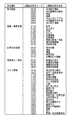
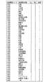
金融機関で利用する場合の主要動向区分コード及び主要動向区分名称の例を図3に示す。図3に示す例では、取引先要項システム4の表示編集制御部8の制御に応じて動向コメントを入力する場合、その動向コメントが属する区分を予め整理している。融資取引の開始は種々の態様があるが、融資取引の開始についての動向コメントは常に00200の「当行融資取引開始」という主要動向区分に属する。
【0044】
主要動向区分管理部16は、この主要動向区分の種別を管理する種別管理機能18を備えている。主要動向区分の区分種別は、図3に示すように、取引先との取引経緯に関する取引経緯種別と、当該取引先の組織や事業の変遷に関する組織・事業変遷種別と、当該取引先の財務会計の基礎事項に関する財務会計基礎種別と、関連会社及び事業施設に関する関連会社・施設種別と、当該取引先への債権等についての信用リスクに関連するリスク管理種別とである。また、主要動向区分の種別として、取引先への営業推進に関する営業推進種別に属する主要動向区分を定義しても良い。
【0045】
図4に動向コメントを取り扱う取引先要項システムのGUI及び内容例を示す。以下、画面や取引先の例を説明のために開示するが、内容は仮想的な事例であり、実在の法人、個人とは無関係である。
【0046】
図4に示す例では、取引先要項システムで取り扱う取引経緯は、取引先動向テーブル100に表示されている。取引先動向テーブル100は、一覧表示として複数の取引先動向レコード(表内の一行)を有しており、この取引先動向レコードは、発生年月日と、主要動向区分と、詳細(動向コメント)と、記入年月日と、記入者とを有する。図4に示す例では、表示編集制御部8が、前記主要動向区分を前記動向コメント入力の必須入力項目として制御する主要動向区分必須入力制御機能20を備えているため、この機能20による制御に応じて、取引先要項システム4で取り扱う動向コメントには、全て主要動向区分が付されている。このため、主要動向区分にない動向については、記載がなされていない。主要動向区分によって動向コメントを明示的に区分することで、主要動向区分に当てはまらない取引先の動向については、不要なものとして、当該取引先要項システムには登録しないことになる。これにより、動向コメントの重要性に関する粒度をユーザーの熟練によらず、システム的に強制し、均質なデータ蓄積を図ることができる。
【0047】
図4に示す例では、融資取引の発生年月日は1960年10月1日であり、同日に、取引開始前の取引先の動向を登録している。記入者欄については、店番やフルネームを表示するが、図中省略している。その後、受手・売掛金事故や、事業施設設置等の主要動向区分に定義された重要事項のみが登録されている。「受手」は、受取手形である。1970年10月には、取引店の変更である移管が生じている。このとき、記入者は長野支店の担当者から本店営業部の担当者となった。その後、上場や子会社の設立を経て、2001年には業績不振となっている。この業績不振に関する動向コメントは、例えば資産査定システム44Bにて当該業績不振に応じた債務者区分の見直しを行った場合には、この資産査定システム44Bから自動的に取得することができる。
【0048】
また、主要動向区分管理部16は、図1に示すように、各主要動向区分を当該区分に属するさらに詳細な主要動向サブ区分を管理するサブ区分管理機能22を備えるようにしても良い。この場合、主要動向サブ区分を用いることで、動向コメントの記載をさらに端的で短いものとすることができ、さらに、横検索での適合率をより高めることができる。サブ区分の例としては、周辺状況の悪化の種類及び程度や、業績不振の度合いや、法的手続申立での適用法律等などがある。
【0049】
好ましい例では、主要動向区分管理部16が、主要動向区分の種別毎の動向コメントの端末1への表示を制御する種別表示制御機能24を備える。種別表示機能により、担当者のスキルを維持及び向上させると共に、取引先の状況を短時間での正確な把握を促す。種別表示制御機能24は、例えば、リスク管理種別に属する動向コメントのみの表示や、組織・事業変遷の種別に属する動向コメントのみを抽出して表示させる。図4に示す例では、全表示と、リスク管理種別のみの表示との二通りを提供している。
【0050】
図5は、動向コメントの種別表示の一例を示す説明図である。図4に示す取引先動向レコードのうち、リスク管理種別に属する主要動向区分が付されたレコードは、受手・売掛金事故と、業績不振の2つである。ユーザーは、このリスク管理種別(管理項目)のみの表示と、全表示との表示を見比べ、リスク管理項目については特に精査するなどの作業により、取引先の動向を短時間で且つ正確に把握することができる。
【0051】
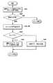
管理項目のみの表示を行うには、図3に示す例では、主要動向区分コードが10,000以上20,000未満の取引先動向レコードを抽出する。図6は、動向コメントの種別表示制御の一例を示すフローチャートである。まず、表示対象の取引先を識別するCIF番号を特定することで、データ格納部3に格納された当該取引先の動向コメント群を特定する(ステップS1,取引先特定工程)。続いて、端末1に表示する主要動向区分の種別を取得し(ステップS2)と共に当該種別等に応じて主要動向区分の抽出範囲を設定する(ステップS3,抽出範囲設定工程)。例えば、図4に示す管理項目表示ボタンの押下があれば、表示する主要動向区分の種別を図3に示すリスク管理種別として、抽出対象の主要動向区分コードを10,000以上20,000未満とする。続いて、取引先動向を1レコード分(一行分)読み込み(ステップS4)、この取引先動向レコードの主要動向区分コードが10,000以上20,000未満であるか否かを判定する(ステップS5)。範囲内であれば、種別の表示対象に追加する。例えば、画面表示用の配列に格納する。そして、取引先動向テーブルの全レコードの読み込みが完了したか否かを確認し(ステップS7)、未読のレコードがあれば、次のレコードを読み取り対象に設定する(ステップS8)。
【0052】
このステップS4乃至S8を繰り返し、抽出範囲設定工程S2,S3にて設定された抽出範囲に属する主要動向区分の全ての取引先レコードを抽出する(範囲内動向コメント抽出工程)。続いて、種別表示対象となった取引先動向レコードを端末1に表示する(ステップS9,抽出表示制御工程)。
【0053】
図1に示す構成や、図6等に示す処理は、サーバーのCPUが所定のプログラムを実行することで実現することができる。取引先要項システムのサーバー及び端末のCPU(図示せず)は、所定のプログラム(指令)に従って各種の演算を行う。CPUは、各種の処理要求に従って端末1の画面に文字データ等を表示し、動向コメントデータ等の入力を促進する。
【0054】
本実施形態では特に、取引先動向表示用プログラムは、下記指令を備える。
表示対象の取引先を識別するCIF番号を特定することでデータ格納部3に格納された当該取引先動向レコード群を特定させる取引先特定指令。
端末1に表示する主要動向区分の種別又は属性を取得させると共に当該種別等に応じて主要動向区分の抽出範囲を設定させる抽出範囲設定指令。
この抽出範囲設定指令に応じて設定される抽出範囲に属する主要動向区分の取引先動向レコードを抽出させる範囲内動向コメント抽出指令。
この範囲内取引先動向レコード抽出指令に応じて抽出される取引先動向レコード群を前記端末に表示させる抽出表示制御指令。
【0055】
この取引先動向表示用プログラムは、磁気テープ(MT)やディスク等の記録媒体11Aに格納されて搬送され、ディスクドライブ11によって読み取られる。記録媒体に格納されていた取引先動向表示用プログラムは、ディスクドライブ11にて読み取られた後、図示しないプログラム記憶部に格納される。また、他のホスト装置から通信回線を経由してプログラム記憶部に当該プログラムを提供することもできる。
【0056】
プログラムについて、CPUを「動作させる指令」というときには、各指令のみでCPUを動作させる指令と、プログラム記憶部に予め格納されているオペレーティングシステム等の他のプログラムに依存して当該CPUを動作させる指令とのいずれかまたは双方を含む。ここでは、「オペレーティングシステム」は広義に解釈している。トランザクションマネージャーや、データベースマネージャーや、実行環境等を含む。
【0057】
営業推進に関する動向コメントを蓄積する例では、主要動向区分の取引経緯種別に対応する主要動向区分を追加するようにしてもよい。好ましい例では、営業推進に関する動向コメントは、他の種別の動向コメントと関係して格納すると、登録及び参照が容易で、且つ理解しやすい取引先動向を生成することができる。この例では、主要動向区分管理部16が、動向コメントに示される取引先の動向と関連した営業推進の内容を対応する動向コメントと関連させて営業推進種別の動向コメントとして登録する動向別推進結果登録機能26を備える。動向別推進結果登録機能26は、事業の展開・変動や、事業施設設置等に区分される取引先の動向と関連して、融資の実行等の営業推進内容を登録する。
【0058】
好ましい例では、主要動向区分管理部16が、営業推進種別の動向コメントを、当該営業推進結果の成約及び不成約を示す推進結果コードで管理する推進結果コード管理機能28を備えると良い。成約は、融資等の契約が成立した場合で、不成約は、融資等の提案を行ったが、取引先から断られた場合と、融資の申込の審査の結果、条件等が合わず、融資の実行ができないと判断した場合とがある。主要動向区分の「謝絶」は、こうした融資の実行ができないと判断した場合の区分であるが、「謝絶」という場合には、手形交換所での取引停止処分を受けているとか、融資の審査に際して、決算書の過度の粉飾を発見した等、より信用リスクの高い状態の意味合いが強く、こうした場合には取引経緯としての登録となる。
【0059】
図7は、営業推進種別の動向コメントを他の種別の主要動向区分と関連させた例を示す説明図である。図7に示す例では、詳細コメントに取引先の動向と、営業推進の内容及び結果を記載している。そして、詳細コメントと記入年月日の間に、営業推進の結果の成約又は不成約を表示している。例えば、1960年10月1日の当行融資取引開始では、成約となっている。このとき、「A信金1行取引から当行取引開始により併行取引となる。手貸10百万円及び当座開設新規成約」とのコメントを記載する。1965年10月1日には、取引店の新しい担当者が営業推進を行い、工場建設及び設備資金で証貸100百万円成約(期間15年)となっている。1973年4月には、子会社の設立に着目し、「運転資金を推進したが、A信金より資金調達」となり、不成約となっている。図7に示す例では、推進項目表示ボタンを押し下げることにより、これらのみ表示することも可能である。
【0060】
図3等に示す例では、動向コメントを区分する主要動向区分は、複数の種別と、各種別に属する区分という階層構造となっている。また、サブ区分を用いる場合には、三階層となる。この階層的な取扱により、取引先の動向の重要性を体系付けることができる。一方、階層的な構造では、ある項目を別の項目に一時的に所属させたい場合が生じる。また、各項目の根拠や関連に関するリンクを付すことができれば、他システムでの作業結果ファイル等との関係をシステム的に取り扱うことができる。このような例では、図1に示すように、主要動向区分管理部16が、取引先についての時系列での主要な動向についての動向コメントデータを区分する主要動向区分を、主要動向区分が属する種別と、当該主要動向区分と、当該主要動向区分内で詳細に区分するサブ区分とのツリー構造で管理する区分ツリー構造管理機能30と、各動向コメントデータに前記ツリー構造とは別に当該動向コメントデータをグループ分けするためのコメント属性又は当該動向コメントデータの根拠等と関連したコメント属性を管理するコメント属性管理機能32とを備えるとよい。
【0061】
区分ツリー構造管理機能30は、主要動向区分を三階層で管理する。そして、コメント属性管理機能32は、各コメントの属性情報を管理する。コメントの属性情報として他システムのファイル名等を格納すると、動向コメントの自動登録と、そのコメントの根拠となる資料のファイル名とを自動的に取引先要項システムに登録することができる。また、例えば、「事業の展開・変動」がリスク管理の対象(原因)となる場合、この属性をリスク管理種別とすることで、管理項目表示に際してこの動向コメントを含めることができる。この例では、図6のステップS3では、主要動向区分コードのコード値と、動向コメントの属性情報とに関して抽出範囲を設定する。例えば、図7に示す推進項目表示ボタンの押し下げによる種別表示では、推進結果コードが属性情報として登録されている動向コメントと、図3に示す取引経緯種別に属する主要動向区分コードが登録されている動向コメントとを抽出し、表示するようにしてもよい。また、主要動向区分のコード値を用いずに、表示用フラグ等の属性情報のみで種別表示を制御するようにしてもよい。また、種別表示と、種別の他システムへの送信はほぼ同様の機能で実現できる。従って、他システムへの種別送信は、主要動向区分のみや、属性情報のみや、両者の使用で実現することができる。
【0062】
<第2実施形態>
第2実施形態では、XML(eXtensible Markup Language)等の構造化されたマークアップ言語(ML)を使用して取引先要項システムを構築する例を説明する。XMLは、SGML(Standard Generalized Markup Language)から派生した文書記述形式であり、SGMLを簡略化すると共に、インターネットでの利用に適合させている。XMLでは、DTD(document type definition)を定義することで、データの用途に応じたタグの体系(タグセット)を使用する。タグの体系を用いることで、要素や属性の文書型を定義することができる。XMLデータは、文書の構造をDTDで定義されたタグで示したテキストファイルである。XMLはSGMLに基づいているため、書籍やWebページ等の非定型文書の処理に適している。例えば、1つの項目に入るデータの長さを予め定めることができず、また、項目数が変化するような文書をRDBで管理することは困難であるが、XMLデータはタグ付けされたテキストデータであるため、文字情報を柔軟に取り扱うことができる。
【0063】
XMLの文書の構造を示すタグの体系は、階層型となっている。階層型は、例えば、生物という要素が動物と植物と微生物とを含み、動物という要素がほ乳類、は虫類という種を含み、というツリー構造である。ツリー構造は、人間にとって、その要素の意味内容を理解する上で有用である。一方、ツリー構造は、コンピュータにとって、要素をノードとする親子関係へのアクセスでデータを操作することができる点で扱いやすい。階層構造で明確に定義された文字データの集合であるXMLデータは、ページのマークアップのみならず、各種のプロパティを管理するためのメタコンテンツの記述や、RDBとのデータ交換や、メッセージングに利用することができる。すなわち、文書の構造を示すタグは、ページ等での表現形式の指定や、要素である文字データのシステムにおける属性の指定や、RDBのテーブルの項目との対応を示す用途に用いられる。
【0064】
タグの体系を定義するDTDでは、要素のデータ型は文字データのみとなっている。指定されたDTDに正しく従っているXML文書を、妥当(Valid)であるという。妥当なXML文書は、DTDに定義されている要素の名前や、階層や、順序や、要素が必須であるか又は任意であるか等の出現回数の指定に従っている。
【0065】
XMLデータを取り扱うソフトウエア・モジュールをXMLパーサー(XMLプロセッサ)という。XMLパーサーは、XMLデータを構文解析し、妥当性の検証等を行う。妥当性が検証されたXMLデータは、予め定められたタグ体系に従っている。XMLデータの内部構造にアクセスするためのAPI(Application Programming Interface)としては、DOM(Document Object Model)やSAX(Simple API for XML)等がある。DOMは、XMLデータを要素や文字データというノードからなるツリー(DOMツリー)として表現する。妥当なXMLデータのDOMツリーは、DTDによる階層定義に従っている。XML文書の要素をある順序でソートしたり、別の場所に移したり、新たな要素を挿入したりする処理には、DOM APIが適している。
【0066】
XMLはサーバーと端末間でデータ及びプログラムを送受信しつつ一定の機能を実現するWebアプリケーションによって利用されることが多く、このため、妥当性の検証を行う機能を持ったXMLパーサー等は、オブジェクト指向言語であるJava(登録商標)向けに開発されたものが多い。Javaの開発環境/実行環境では、クラス階層が既に定義されており、また、多重継承を行わずにインタフェース(他の言語では、プロトコルとも呼ばれる)を活用することで、モジュールやコンポーネントと呼ばれるプログラムの部品の再利用性と独立性を高めている。Javaの開発環境では、XMLの妥当性検証などは既存のモジュールを利用することができる。また、Webアプリケーションの開発、特にJ2EE(Java 2 Platform, Enterprise Edition)では、データベース、サーバー及び端末を概念的、役割的に三層から五層に分けて把握する。例えば、J2EEでは、GUIを生成するためのプレゼンテーション機能を提供するWeb層と、アプリケーションロジックを実行するためのEJB層とを分離することができる。EJB(Enterprise Java Beans)は、J2EEでのビジネスロジック用のコンポーネントであり、EJBの実行環境であるEJBコンテナがトランザクション処理、セキュリティ、負荷分散等の詳細を管理するため、EJBのプログラマはビジネスロジックのコーディングに集中することができる。例えば、EJBを用いると、分散トランザクションは自動的にサポートされ、複数のデータベースを利用しても、トランザクションの原子的な更新を行うことができる。これは、例えば、取引先要項システムのデータベースへのデータの登録と、他システムのデータベースへのデータの登録とを一つのトランザクション内で原子的に格納することを容易に実現できることを意味する。
【0067】
J2EEでは、端末は、Webブラウザか、GUIを装備したJavaアプリケーションを用いる例が多い。Javaアプリケーションを利用する場合には、GUIとしてSwing又はこれを利用した画面設計ツールを用いると、GUIの定義が容易となる。EJBは、端末1のJavaアプリケーションとセッションを維持し、ボタン押下等のイベントを直接に又はプレゼンテーション層を介して受信することができる。EJBは、イベントに応じて、表示モードの変更を指示したり、要素間での構成比率の算出を行ったり、導出元の入力を検索キーとしてRDBから検索し、DOMツリーを操作して検索結果を導出先の要素として追加したり、要素のソートを行うことができる。要素のソートをプレゼンテーションの問題と捉える場合には、このソートをプレゼンテーション層に実装する。
【0068】
XMLデータのデータベースへの格納には、種々の方式が提案されている。XMLのタグをRDBのテーブルにマッピングし、RDBに格納する方式や、XMLデータを巨大なテキストデータとして格納し、検索用のインデックスをサイド表として生成する方式や、オブジェクト指向データベースでのクラス階層にXMLデータをマッピングする方式などである。
【0069】
XMLデータの操作では、DOMツリーを用いるのではなく、コンプレックスレコードのスキーマ定義を行い、XMLデータのタグと、Javaのオブジェクトと、データベースのレコードとを任意のタイミングで相互に変換可能とする開発・実行環境も提供されている。また、文書型定義をよりXML関連技術で使用しやすくするための手法として、XMLSchemaが定められている。XMLSchemaを用いる場合には、XMLデータの妥当性検証にてデータ型等の検証を行うことができる。
【0070】
本実施形態では、DTD、DOMツリー、XMLデータをテキストとして格納しサイド表を用いてSQLでの検索を可能とするデータベース、J2EEによるEJB、さらに、SwingによるGUI、Webブラウザで実行されるアプレット、EJBやサーブレットやアプレットを使用した型チェックや表示編集制御、RDBを用いた他システムからのデータの取込等の技術を利用する。DTDや、DOMツリーや、SQLによる検索や、アプレット及びWebブラウザに代えて、XMLSchemaや、コンプレックスレコードや、XQueryや、WebブラウザとXSLTの組み合わせ等を用いるようにしてもよい。端末をPDAや携帯電話等の携帯端末とする場合、例えば表示のみを提供するために、XMLデータをXSLTでHTMLに変換し、送信する仕組みとしてもよい。
【0071】
図8は、第2実施形態の構成例を示すブロック図である。本実施形態による取引先要項システムは、RDBと連携するマークアップランゲージ(ML)のタグの体系を定義したタグ体系定義ファイル50と、端末での表示及び入力について予め定められたGUI定義ファイル52と、前記MLのタグ付けされた取引先毎のタグ付きデータを格納するMLデータDB(図8に示す例では、XMLデータDB)54と、他システム40にて一定期間毎に更新されるデータを格納したRDB56とを格納するデータ格納部3とを備えている。
【0072】
タグ体系定義ファイル50は、例えばDTDファイルである。GUI定義は、Swing等による画面のレイアウト定義と、各画面で使用するテーブルの項目(フィールド)と関連して定義したデータ型等と、項目間の導出関係の定義と、表示のプロパティデータと表示するボタン等の関係等である。XMLデータDB54は、例えば、XMLを巨大なテキストファイルとして格納し、検索用のサイド表を作成するRDBの拡張を用いると、項目数の増減について比較的柔軟な取扱が可能となる。RDBは、IMS等の階層型データ構造を使用するオンラインシステムのデータを取り込む機能を有するRDBを用いるとよい。
【0073】
図8に示す例では、サーバーは、取引先の組織及び事業並びに主要な動向等についてのデータの端末での表示及び入力を前記GUI定義に従って制御する表示編集制御部8と、他システム40から取り込んだデータ及び端末1から入力されたデータをRDB56でのデータ項目名若しくは前記GUI定義に関連した前記タグ体系定義に基づいてタグ付きデータに変換すると共に、当該タグ付きデータを一体的な要項データとして前記MLデータDBに格納する格納制御部10とを備えている。
【0074】
表示編集制御部8は、プレゼンテーション層のソフトウエア群と、ビジネスロジックを実行するEJBである。格納制御部10は、XMLデータDB54へXMLデータを格納するためのEJBコンポーネントと、格納前にDTDによる検証を行うパーサーモジュールと、例えばJDBC等を用いる場合にはJDBCのAPIをXMLデータDB54のAPIにマッピングするDB54のドライバー等である。
【0075】
表示編集制御部8は、GUI定義と取引先の態様とに応じて、当該取引先の態様毎に入力不可とする項目を制御する入力不可制御機能60を備えている。この機能60は、例えば法人であれば屋号フィールドの入力を不可にする一方、個人事業主であれば入力可にする等の制御を行う。これにより、種々の人格で利用する全てのタグを1つのDTDで定義し、また、画面のレイアウトも法人と個人事業主とで同一とすることができる。
【0076】
また、表示編集制御部8は、他システム40にて更新されるデータをタグ体系定義に基づいて取得すると共に、導出元項目への入力からGUI定義に基づいて導出先項目の内容を導出する制御をする導出制御機能62を備えている。他システム40で更新されるデータのうち、オンラインシステム42から基盤DB等を介して月次で取得する基本属性データや融資基本属性データは、CIF番号をキーとしてRDBで管理されている。このため、取引先要項の各種のテーブルで、CIF番号を有するレコードでは、CIF番号から、氏名又は名称、住所、融資先番号、主取引店、業種コード等を導出することができる。
【0077】
導出制御部62は、導出元項目であるCIF番号から、導出先項目である氏名又は名称等を導出する制御を行う。導出制御は、例えば、プレゼンテーション層では、導出元項目がアクティブになり、入力が開始された場合に、導出先項目をグレーアウトするなどして入力不可とする。EJB層では、CIF番号を検索キーとしてRDB56から必要な項目のデータを抽出し、DOMツリー又は画面表示用に編集したデータの対応する導出先項目へ挿入する。
【0078】
導出制御部62は、さらに、構成比率の算出等を行う。例えば、取引先の発行済株式数が判明しており、大株主とその持株数を取引先要項に登録する場合、発行済株式数と各株主の持株数から、各株主の持株比率を算出する。株数を入力するフィールドが導出元で、持株比率が表示するフィールドが導出先となる。これらの導出は、実際には、導出ボタンの押下か、登録ボタンの押下があったときに、端末1からデータを受信し、RDB56の検索や比率算出をサーバー側のEJBで行う。
【0079】
好ましい例では、表示編集制御部8が、入力不可制御機能60によって入力されない項目及びユーザーから入力されない項目について、タグ付きデータを生成しない空タグ非生成制御機能64を備える。入力不可制御機能60によって、人格によらない単一のDTDを使用することができる。そして、空タグ非生成制御機能64は、入力されない項目についてはタグを生成しないため、結果的に、単一のDTDから、個人事業主のXMLデータは個人事業主に用いるタグのみを使用し、法人のXMLデータは法人に用いるタグのみを使用することとなる。例えば、取引先が法人の場合には屋号は入力されないため、屋号の空タグは生成されず、このため、法人向けのみにDTDを作成するのと同様のXMLデータを得ることができる。これにより、他システムへのデータ送信の構築をより簡易にすることができる。
【0080】
本実施形態では、表示編集制御部8は、取引先の基本属性、組織及び事業の内容の参照及び編集を要項Iデータとして管理する要項I管理機能66と、主要な動向を時系列で記録する動向コメントの参照及び編集を要項IIデータとして管理する要項II管理機能68とを備えている。より広く取引先の情報を集約するには、例えば、要項IIIとして保証人に関するデータを管理したり、要項IVとして融資方針に関するデータを管理するようにしても良い。本実施形態では、要項I及びIIについてDTD及びGUIの例を説明する。
【0081】
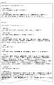
図9は本実施形態で利用するDTDの一例を示す説明図である。DTDの記載は、SGMLによる。yoko2.dtdは取引先要項IIのDTDである。取引先要項IIという要素(ELEMENT)は、CIF番号と、取引先動向とを有する。取引先動向末尾の+は、この要素が1回以上出現することの指定である。末尾に何も付加されない場合には必ず1回出現する指定で、?は0回又は1回、*は0回以上である。末尾なしと+は必須項目であり、+と*は、XML上は繰り返し何度書いても良い。?と*は出現しないこともある。このため、要項IIデータは、CIF番号の取引先について、1つの取引先動向が入力されると生成される。取引先動向は、繰り返し何度記入しても良い。
【0082】
取引先動向は、発生年月日、主要動向区分コード、主要動向区分名称、詳細コメント、記入年月日、記入者所属店番、記入者所属店名、記入者ユーザーID及び記入者氏名を有する。詳細コメントは、動向コメントであり、要項IIデータは、主要動向区分と発生年月日が入力されると、コメントが存在しなくとも登録する。このDTDによる要項IIデータの一例を図11に示す。
【0083】
yoko1.dtdは、取引先要項Iの定義である。基本属性として、業種コード及び業種名が括弧でくくられているのは、業種コードが入力される場合には業種名も必要であるとの指定である。括弧の外に?が付されているため、業種コードと業種名のセットの出現回数の指定は0回又は1回である。顧客として、基準日、基本属性等を定義している。この顧客は、他システム40のデータをRDB56に格納し、取引先要項システムが取得するデータである。この顧客に属するデータは入力不可とする。この顧客のタグ定義は、XMLデータの履歴等の保存用の定義である。(生年月日|設立年月日)とあるのは、生年月日又は設立年月日の一方という意味である。個人の場合には前者で、法人の場合は後者である。当行というのはこの取引先要項システムを使用する主体で、当社は取引先である。要項IのXMLデータの例を図12及び図13に示す。
【0084】
図示する例では、理解を容易とするためにタグを全角日本語で表記しているが、ソフトウエア及びプログラムとしてはアルファベットや数字が扱いやすいため、実際には英文表記又は日本語のローマ字表記を用いるとよい。
【0085】
好ましい例では、格納制御部10が、当該要項データの履歴の格納指令を受信した場合に、前記他システムからのRDBデータにて前記基本属性データを更新すると共に、当該基本属性が更新された要項Iデータを当該要項Iの履歴データとして格納する制御をする履歴格納制御機能78を備える。要項Iは、役員等や、事業内容や、製商品等最新の情報で更新されていく項目を扱う。このため、履歴格納制御機能78は、年に1度等の頻度で、その1年間に要項Iデータが更新された取引先について、要項Iデータの履歴を格納する。要項Iの履歴を管理するため、図9の履歴では、履歴の作成日をXMLデータ自体の要素として定義している。
【0086】
また、自己査定の根拠資料として取引先要項を添付する場合には、査定の時点での取引先要項が必要であるため、履歴格納制御機能78は、他システムからの要求に応じて、RDBデータで更新し、現在の要項Iデータ及び要項IIデータを履歴として格納する機能を用いて、他システムにデータを送信するようにしても良い。ただし、要項IIは、取引先動向をその発生年月日で管理するものであるため、それ自体が最新のデータで、且つ履歴である。このため、一定の頻度での履歴を特に作成する理由はほとんどない。
【0087】
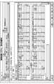
図11を参照すると、CIF番号、発生年月日は、切れ目のない固定長の数字列となっている。本実施形態では、XMLデータとしてはハイフン等を含ませず、表示のデータ型の一種として、GUI定義にてハイフンの挿入等を行う。yoko2.dtdでは、取引先要項は唯一のCIF番号と、これと並列の1つ以上の取引先動向とを有する。タグによる文書型の指定は、<タグ名>で始まり、</タグ名>で終了する。階層に応じてこのタグが重ねて定義される。例えば、主要動向区分コードは、取引先動向に属し、取引先動向は、取引先要項IIに属する。この階層は、ツリー構造のDOMツリー等で管理することができる。主要動向区分コードと、主要動向区分名称の関係については、図3に示すとおりである。
【0088】
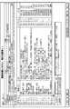
図12を参照すると、取引先要項IのXMLデータは、CIF番号の次が、更新となっている。この順序は図9の取引先要項Iという要素の子要素を定義する括弧内の順序である。更新の次は顧客であるが、ここでは省略している。役員等の役職従属関係コード及びその名称は、当社(取引先)と役員等との関係を予め一覧表にしたものであり、図21に一例を示す。役員等での、代表権有無コードの1は有りで、無しの場合には0となる。代表権のみならず、全ての有無コードで1又は0とする同様の取扱としてもよい。
【0089】
図14から図20は、取引先要項Iの画面例を示す説明図である。要項Iでは、組織と事業との2つの区画(ページ)を定義し、タブで遷移する。要項Iデータの内容として、組織の内容を表示する組織区画に、連絡先、屋号、従業員数、役員等、経理担当者、当行出身者、資本、大株主(大口出資者)、事業施設、関連融資先名寄せ、その他関連先、会計事務所、当行関連会社利用状況、及び有価証券保有状況の各テーブルを有する。そして、事業の内容を表示する事業区画に、平均月商、事業内容、製商品、特記事項、資金決済、販売先、仕入先、ホームページアドレスの各テーブルを有する。特記事項は、事業内容及び製商品の特色に関するコメントと、業界の地位に関するコメントである。
図14等に示す例では、入力可能な項目及び全体の更新日は2002年2月10日で、RDB56から取得するデータの更新日は、2月の前月末であるため、2002年1月31日である。要項Iについては、組織のページと事業のページとをスクロールすると、その取引先の全体的な概況を把握することができる。このため、更新者が、変更又は追加した項目についての更新者ではなく、要項Iデータの全体について2月10日に確認したこととして取り扱うことができる。
【0090】
DTDによる階層と、画面表示の階層は異なっている。DTDの要素定義は、意味内容の体系ではなく、RDBからの取得するデータを顧客としてまとめ、また、入力される顧客に関するデータを顧客その他としてまとめている。DOMツリーはDTDの階層で生成される。プレゼンテーション層では、すなわち、表示編集制御部8は、このDOMツリー構造のデータを上記画面表示での体系に編集し、画面表示用のデータとして、配列等で取り扱うとよい。例えば、各テーブルの処理を行うEJBが、DOMツリーから必要な項目を読み出す。本実施形態では、取引先の平均月商は、平均月商テーブルと、事業内容テーブルと、製商品テーブルと、販売先テーブルで用いられている。そして、画面表示し、編集された結果のデータについては、格納制御部10が、配列等からDOMツリーを構築し、妥当性の検証を行った上でXMLデータDB54への格納を行う。
【0091】
A産業株式会社は法人であるため、屋号の名称は入力不可となっている。入力が不可であるフィールドは、グレーアウトするとよい。ここでは、フィールド(各項目を入力するボックス)の左上及び右下の斜線で、入力不可であることを示している。CIF番号のフィールドの左上に、黒丸が付されている。この黒丸は、そのフィールドが導出元の項目であることを示す。役員等の社長のCIF番号を入力すると、氏名及び生年月日が導出される。導出先のフィールドは入力不可であるため、グレーアウトされている。この役員等のテーブルは、5レコード分表示しているが、6レコード以上のデータが登録される場合には、右のスライダーを操作することで6番目以降の内容を参照することができる。
【0092】
好ましい例では、表示編集制御部8が、取引先を当社とした場合の当社の役員等の自然人と、当社の大株主(大口出資者)及び販売先等の法人若しくは事業性個人とを識別するCIF番号を任意入力項目として管理すると共に、当該CIF番号が入力された場合には当該CIF番号を導出元として当該テーブルの名称項目及び住所項目等を導出するCIF番号別入力支援機能70を備えるとよい。
【0093】
図14に示す例では、役員等の常務で大阪四郎は、CIF番号を有していないため、氏名が直接入力されている。通常のRDBでは、CIF番号のようなキーとなる値を入力せずに、そのテーブルの項目の入力を許可することはできない。しかし、本実施形態では、データの構造はXMLであり、各項目を任意とすることができる一方、CIF番号が入力された場合には導出を行うことができる。DTDによるタグ体系の定義と、導出というビジネスロジックを分離したことで、CIF番号を任意入力項目としつつ、入力された場合には導出するという柔軟な取扱を行うことができる。
【0094】
また、好ましい例では、表示編集制御部8が、従属関係管理機能72を備えるとよい。従属関係管理機能72は、取引先の役員の役職項目と、当該取引先と当該取引先への大口出資者との関係項目と、関連融資先及びその他関連先と取引先との関係項目とで使用する関係を示す従属関係コードを用いて、当該各項目の入力を管理する。従属関係コードを用いて、取引先と関係する個人又は法人等の関係を登録するため、横検索を精緻に行うことができる。図14に示す役員等のテーブルでは、役職はコンボボックスによる選択が可能となっている。これは、図21に示す従属関係コードの内、役職にフラグが立っている項目を役職従属関係コードとするものである。コンボボックスは、そのリストからの選択を促す。コンボボックスであることを、そのフィールドに下向き黒三角を配置することで示す。コンボボックスでは、リスト以外の内容を入力することはできないため、情報を均質にすることができる。また、コンボボックスであっても、DTDの定義に従って値を入力しないことはできる。
【0095】
図21に示す従属関係コードは、社長、会長、副会長と一定の順序で体系化されている。XMLの同一要素についての複数レコードは、本実施形態でのDTD上、シーケンス番号や、順序の概念はない。本実施形態では、役員等の役職をコード化し、かつ表示すべき順序で従属関係コードの番号を与えている。そして、役員等のレコードの並び(XMLデータの複数ある同一要素の並び)を従属関係コードの小さい順としている。すなわち、本実施形態では、表示編集制御部8が、役職欄の各レコードを従属関係コードの値に基づいて並べ替える従属関係コード別ソート機能74を備える。これにより、入力及び登録した順ではなく、予め定められた順序で表示することができ、項目毎にシーケンス番号等を付与することなく、項目の視認性を向上することができる。そして、ある専務が社長となった場合には、役職欄を選択し直すのみで、従属関係コード別ソート機能74による最適な順序での表示に更新されることとなる。このソートは、サーバー側のEJBで行う場合にはサーバーの機能であり、端末側のアプレットで実行する場合には端末側の機能となる。この従属関係コード別ソート機能74は、図14等に示す例では、登録ボタンが押し下げられたときに各テーブルの項目を従属関係に従ってソートする。
【0096】
図21に示す例では、従属関係コードは、法人、個人及び役職のフラグが付されている。これにより、法人の場合の従属関係と、個人事業主の場合の従属関係と、役職従属関係の場合とで、個別のコード体系とすることができる。この例では、表示編集制御部8が、取引先の人格に応じて当該人格向けの従属関係コードを生成する従属関係コード生成機能76を備えるとよい。
【0097】
図15に示す例では、大株主(大口出資者)の持株数を導出元とし、合計と各株主の持株数から、持株比率を導出している。この導出は、EJBで行う。図16に示す例では、関連融資先の名寄せ管理を行う。このとき、当社との関係で、従属関係コードを用いる。A産業株式会社は法人であるため、図21に示す従属関係のうち、法人フラグが1になっている従属関係コードからこの関係を選択する。関連融資名寄せ(グループ名寄せ)は、信用リスク管理や、保証の内容や、実質同一である関係者等の把握等に役立つ。本実施形態では特に、従属関係コードを用いて相関関係を整理するため、グループ全体に対する信用リスク管理の精度の向上を図ることができる。また、当社とAオプトデバイスの関係が子会社である場合、Aオプトデバイスの関連融資先名寄せでは、子会社の反対概念をA産業に対して自動的に付することもできる。
【0098】
図17に示すその他関連先は、例えば、当行との取引はないが、当社と関連する企業等である。有価証券保有状況で、当行所有当社株式は、取引先要項システムを使用している主体が、取引先の株式を所有している場合であり、当社所有当行株式は、その逆である。
【0099】
図18及び図19に示す事業区画では、事業内容や事業内容毎の平均月商と、平均月商合計とから、事業内容の構成比率を導出している。資金決済は、例えば、支払締切日であれば、請求を受けた当月の末日に締め、これを翌月の15日に支払う場合、図示のとおりとなる。欄が2つであるのは、相手先によって支払日が異なる場合や、年2回の決算(6ヶ月決算)を行う先では、決算月が2つになるためである。図10の資金決済で、支払締切月1・区分コードは、図18の資金決済テーブルの左側の欄での当月を表すコードであり、支払締切月1・月区分名称は、例えば当月である。賞与支給月2・月コードは、図18に示す例では12で、賞与支給月2・月は12月である。
【0100】
図19及び図20に示す販売先及び仕入先では、CIF番号を任意入力項目としつつ、入力された場合には氏名、住所、融資先番号等の導出元としている。主取引店は融資先番号から導出する。表示編集制御部8は、当社からみた販売先毎の平均月商を入力すると、その構成比率を導出する。現金比率は、売上に対する入金のうち、何割が現金であるかの値である。仕入先についても同様に、ユーザーが知り得た範囲で、仕入先から当社に販売している平均月商の、現金比率を入力する。この仕入れの平均月商と、現金比率と、資金決済日との関係から、一月での資金需要を求めることもできる。資金決済日として入金日も登録する場合には、キャッシュフローを分析し、最適な資金調達の提案等も行うことができる。また、資産査定にて正常な運転資金を算出するのに、この実態を参照することもできるようになる。
【0101】
図22は、表示モード変遷の一例を示す説明図である。表示編集制御部8は、図22に示すように、すべての項目を入力及び編集不可とする参照モード80と、他システムから取得した項目及び導出先の項目を入力及び編集不可とすると共に他の項目の入力及び編集を許可する編集モードと82、要項Iにて編集モード82での編集結果で各テーブルの内容をソートして表示を行うと共に当該表示した内容での登録の確認を促す確認モード84とを備えている。要項IIでは、登録や削除前にそれぞれの確認を促す確認メッセージ85を表示する。
【0102】
ユーザーは、取引先要項システム又はこれを含む融資支援システム等にログインすると、CIF番号を入力し、要項I又はIIの選択を行う。図23は、各編集モードで表示する編集ボタンと、そのボタン押下のイベントを受信した場合の処理内容等の関係を示す説明図である。例えば、要項Iを選択して、開くボタンを押し下げる。すると、要項Iの参照モードへ遷移する。参照モードでは、選択画面へ遷移する戻るボタンと、要項IIの参照モードへ遷移する要項IIボタンと、編集モードへ遷移する編集ボタンとを取り扱う。編集ボタンは、編集権限のあるユーザーの場合にのみ表示し、要項IIボタンについても、要項IIの参照権限のあるユーザーの場合にのみ表示する。編集モードでは、入力可能なフィールドについてはグレーアウトを解除し、入力及び編集を可能とする。戻るボタンの押下があると、編集内容を破棄して、要項選択画面に推移する。編集モードで登録ボタンが押し下されると、ソート等を行って、編集不可の状態で画面に編集後の内容を表示する確認モードに遷移する。確認モードでは、登録の可否を問い合わせ、はいボタンが押し下げられると、確認のダイアログボックス等での確認の後、編集結果を含む要項Iデータの全体をXMLデータDBへ更新する。元に戻すボタンの押下では、今までの編集結果を維持しながら編集モードへ戻る。要項選択画面と、要項Iと、要項II間で遷移する場合、すでに入力されたCIF番号を引き継ぐようにしている。従って、要項Iを参照し、要項IIボタンを押し下げると、同一の取引先の取引先要項IIの参照となる。
【0103】
図14等に示す例では、各テーブルの左端に削除チェックボックスがある。編集モードにて削除対象のレコードを選択し、チェックボックスをオンとした状態で、登録ボタンを押し下げて確認モードに遷移すると、表示編集制御部8は、削除チェックボックスがオンとなっているレコードを削除して確認用に画面表示する。この状態で登録すると、チェックしたレコードが削除される。
【0104】
図24はユーザーのログインから端末への要項データの表示までの概要を示すフローチャートである。取引先要項システムは、取引先要項システムにログインした作業者をユーザーIDに基づいて識別する(ステップS11)。ユーザーは、CIF番号を入力し、且つ要項I又はIIを選択して開くボタンを押し下げる(ステップS12)。ユーザーID等から取引先要項の参照権限を確認し(ステップS13)、権限がある場合には、当該CIF番号の取引先について、RDB56から取引先の基本属性等のデータを取得し(ステップS14)、これに前後して、XMLデータDBからXMLデータを取り込む(ステップS15)。さらに、ユーザーの権限に応じたボタンの表示制御を行い(ステップS16)、GUI定義による画面定義ファイルと取り込んだデータとを合成して端末1に表示する(ステップS17)。
【0105】
ユーザーの権限に応じて編集の可否を制御する例では、要項I及び要項IIに関して、表示編集制御部8は、ユーザーの所属店番と、取引先の取引店の店番との関係に基づいて、参照モードから編集モードへの遷移を要求するメッセージをサーバーに送信する編集ボタンの表示及び非表示を制御するボタン表示制御機能90を備える。図25は、ユーザーの所属店番と、取引先の取引店との関係に応じた権限設定の一例を示す説明図である。取引店は、主取引店か、または、複数取引のある場合の取引店である。他店は、ユーザーの所属店が主取引店でも複数取引の取引店でもない場合である。本部は、審査、監査、秘書室その他の本部組織である。図25に示す例では、他店の場合には要項Iの参照のみ許可する。従って、要項I参照モードでは要項IIボタンを表示しない。取引店担当者は、GUI定義等によって入力不可とされていない項目について、編集及び削除が可能である。しかし、取引先動向は本来的に削除するものではないため、取引先動向の削除には一定の権限を要することとした。本部は、要項I及びIIの参照のみを可能としている。
【0106】
図25に示すアクセス制御を行う例では、表示編集制御部8が、自他店別アクセス制御機能92を備えると良い。自他店別アクセス制御機能92は、ユーザーの所属店番と、取引先の取引店(主取引店及び複数取引の場合の取引店)の店番とが同一の場合に、要項Iデータ及び要項IIデータの参照及び編集を許可する。一方、自他店別アクセス制御機能92は、ユーザーの所属店番と、取引先の取引店の店番とが異なる場合に、前記要項Iデータの参照を許可すると共に、要項Iデータの編集及び要項IIデータの参照及び編集を不許可とする。
【0107】
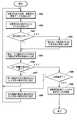
図26はユーザーの権限を判定する処理例を示すフローチャートである。取引先要項システムは、ログインに成功した作業者を識別すると(ステップS21)、続いて、取引先が融資先番号を有しているか否かを確認する(ステップS23)。取引先要項システムは、取引店情報を特定できる融資先番号を保有する取引先について、その情報を蓄積するものであるため、融資先番号を保有していない取引先は要項作成の対象外となる。取引店情報は、取引先と取引を行う一又は複数の営業店(取引店)を特定する店番等を含む。また、見込み先等取引実績のない先についての情報を蓄積する場合には、見込み先に融資先番号を付与するか、またはこのステップS23を見直す。続いて、ユーザーの所属店を確認する(ステップS24)。本部のユーザーである場合には、参照のみ可となる。一方、営業店の場合には、まず、要項の選択がI又はIIのどちらであるかを確認する(ステップS25)。要項Iの場合、ユーザーの所属店番と取引先の取引店の店番が一致する場合には、編集ボタンを表示して(ステップS27)、参照及び編集を許可し、要項Iの参照モード画面に遷移する。この条件では、要項IIの参照及び編集も同時に許可されるため、要項IIボタンも表示する。一方、不一致の場合には、他店であるため、編集は不可としつつ、参照のみを許可する。この場合は、要項Iの参照が不許可のため、要項IIボタンも表示しない。
【0108】
要項IIの場合、ステップS28で他店であるか否かを確認し、他店である場合には参照をも不可とする。従って、取引先要項選択画面から要項II画面への遷移は行わない。一方、ユーザーの所属が主取引店又は複数店取引がある場合の取引店であれば、編集ボタンを表示して(ステップS29)、参照及び編集を許可し、要項IIの参照モード画面に遷移する。この条件では、要項Iの参照及び編集も同時に許可されるため、要項Iボタンも表示する。
【0109】
次に、XMLデータDB等への多重書き込みによるデータの不整合発生を防止するためのロックについて説明する。この例では、サーバーが、同一の取引先についての複数のユーザーによる同時多重参照を許可すると共に、同一時刻で複数のユーザーが同一の取引先について編集モードとならないように編集モードの排他制御を行うロック制御部94を備えている。図22等に示すように、本実施形態では参照と編集とを明確に分離している。同時に多数のユーザーが参照したとしても、書き込みが行われないため、ロックする必要がない。一方、一人のユーザーが編集モードへ遷移した後に、他のユーザーへも編集を許可すると、二重の書き込みが生じ、一方の更新が破棄されてしまう。このため、本実施形態では、参照については多重アクセスを許可しつつ、編集モードについては確認モードを介した登録か、要項選択画面へ戻ることで編集を中断するまで、CIF番号単位にロックすることとした。
編集モードを明確に定義し、参照時には追加、更新、変更等の全ての編集を不可としたため、排他制御は編集モードへ遷移する場合と、編集完了後、登録時とに行うことができる。本実施形態では、他システムから取引先要項システムのデータ格納部3へのアクセスを参照モードと同様に取り扱うことで、システム間の排他制御という複雑な処理や、データベースの二重化等の設計を回避することができる。
【0110】
また、J2EE等を用いたWebアプリケーションでは、PC等の端末がクラッシュし、端末とのセッションが強制的に切れてしまい、ロックを確保した状態だけがサーバーに残ることも想定できる。
【0111】
図8に示す例では、ロック制御部が、ロック取得制御機能96と、ロック解放制御機能97と、ロック可否判定機能98とを備えている。この例では、当該取引先のCIF番号と、ロック取得(獲得)するユーザーのユーザーIDと、現在時間である開始時間と、開始時間に予め定められたロック最長時間を加算した終了時間とからなるロック管理情報をRDBに格納し、このロック管理情報を参照してロックの可否を判定する。このとき、ロック管理情報によるロック中のユーザーが自分であるか否かを判定する処理と、ロック最長時間が経過した場合には端末からの操作がなくとも強制的にロックを解除する仕組みとしたことで、端末の強制終了による混乱を回避することができる。
【0112】
ロック可否判定機能98は、ロックの判定対象となる取引先のCIF番号で識別されるロック管理情報のロック終了時刻が、現在時刻よりも未来であり、且つ、当該ロック管理情報でのユーザーIDが異なる場合に、ロックが取得されていると判定する。
【0113】
具体的には、ロック取得制御機能96は、図27に示すように、編集モードへ遷移する時に(ステップS41)、当該CIF番号の取引先の要項データ全体に他のユーザーによってロックが取得されているか否かをロック管理情報に基づいて判定する(ステップS42)。ロックが取得されていない場合には、自分のロック管理情報がないことを確認した後に(ステップS43)、ロック管理情報を書き込む(ステップS44)。もし、自分のロック管理情報がある場合には、ロック情報の終了時刻を更新する(ステップS45)。
【0114】
ステップS42にて、ロック中のユーザーがいる場合には、ロック管理情報のユーザーIDを比較して、自分自身であるか否かを確認する。端末が強制終了し、再起動後にロック終了時刻前に編集ボタンを押し下げた場合、自分自身がロック中となっている。自分自身のロックである場合には、ロック情報を更新し(ステップS50)、当該XMLデータをロックして、編集モードを開始する。
【0115】
ステップS44又はS45に続いて、ロック情報を再度確認し、ロック情報を同一タイミングで書き込んだ他ユーザーがいるか否かを判定する。自分がステップS42の直後からステップS44の完了までの間に、相手がステップS42でのロック情報の読み込みを行った場合に、他ユーザーが存在する。また、逆の場合にも先行する他ユーザーが存在する。他ユーザーがいなければ、ロックを取得し、編集モードに遷移する。一方、他ユーザーがいる場合、ロック開始時刻の早いユーザー又はその他の手法で唯一のユーザーを選択する(ステップS47)。他ユーザーが選択された場合には、ロック終了時刻を更新し、ロックを解除する(ステップS48)。ステップS48及びS49にて、他のユーザーが既にロックを取得している場合には、編集を不可とし、多重アクセスが生じた旨のメッセージを端末に表示するようにしても良い。
【0116】
ロック解放制御機能97は、ステップS28に示すように、編集モードにて編集された内容が登録される時に(ステップS61,62)、当該CIF番号の取引先の要項データ全体に他のユーザーによってロックが取得されているか否かをロック管理情報に基づいて判定する(ステップS42からS50)。そして、ロックが取得されていない場合には(ステップS63)、当該登録処理を許可すると共に、登録後に当該CIF番号のロック管理情報の終了時刻を現在時刻に更新する(ステップS64)。一方、ロックが他ユーザーによって取得されており、ロック不可の場合には、編集結果の登録を不可として、元に戻すボタン等による編集の中断を促す。このとき、多重アクセスが生じた旨のメッセージを端末に表示するようにしても良い。ステップS62で中断と判定した場合には、ロック終了時刻を現在時刻に更新して、ロックを解放する。
【0117】
図29は取引先要項IIのGUIの一例を示す説明図である。要項IIのGUIは、動向コメントを時系列で表示すると共に表示のみで変更を不可とする取引先動向テーブル100と、参照モードでは既存の動向コメントを表示すると共に、編集モードでは既存の動向コメントの編集及び新たな動向コメントの入力作業領域となる表示・入力・編集エリア102とを備えている。取引先動向は原則的に編集する文字データではないため、取引先動向テーブル100では、編集を不可としている。新しい動向コメントの入力等は、表示・入力・編集エリアで行う。
【0118】
図29に示すように、要項IIでの編集モードでは、表示・入力・編集エリア102の近傍に、クリア、追加、変更、及び削除の各ボタンを配置する。ユーザーは、発生年月日を入力し、主要動向区分を選択し、詳細(動向コメント)を記入して追加ボタンを押し下げると、当該エリア102に記入した内容が取引先動向テーブルに反映される。反映の可否に関する確認メッセージに対して、はいボタンを押し下げることで登録し、参照モードに戻った状態を図30に示す。このエリア102は、取引先動向テーブル100にて表示しきれない部分を表示するためにも用いられる。
【0119】
取引先動向テーブル100では、発生年月日をソートのキーとして取引先動向のレコードをソートしている。このため、例えば、数年前での主要な動向が判明し、その動向コメントを入力すると、発生年月日を数年前とすることで、記入・登録順序とは無関係に、発生年月日順に並べ替えられる。XMLデータは、この並べ替えられた状態で生成及び格納される。
【0120】
営業店内といえども、担当者及びその上司限りとすべき情報を得ることがある。例えば、M&A等を近日のある日付で実行する等の情報は、取扱に注意を要する。一方、その発表日になった瞬間に、種々の対応を迫られることとなる。このような場合に、発生年月日を将来の日付として登録しておき、その日付を解禁日とし、その日付を迎えた段階で表示するようにすると、当日には要点がすでに取引先要項システムに登録されており、その情報を組織内で即座に活用できる。取引先要項システムでの要項IIは、過去に生じた取引先の動向のうち、重要なものを登録するものであるが、この過去の結果を登録するという仕組みの例外として、解禁等の仕組み導入するには、表示編集制御部8が、表示・入力・編集エリア102にて将来の日付が入力されて当該将来日付の動向コメントデータを登録した場合には、当該ユーザー等によって許可されないユーザー群に対する表示については、当該将来日付が到来するまで当該将来日付の動向コメントを表示しない制御をする解禁指定登録制御機能99を備える。
【0121】
図31は、分析制御部を備えた取引先要項システムの一例を示すブロック図である。この例では、サーバーが、取引先の要項についてマークアップランゲージ(ML)でのタグ体系を定義したタグ体系定義ファイル50と、MLのタグ付けされた取引先毎のタグ付きデータを格納するXMLデータDB54とを格納するデータ格納部3と、タグ体系定義ファイル50によって定義される取引先の組織及び事業並びに各取引先の販売先及び/又は仕入先に関する販売先等関連項目についての要項データの端末1での表示及び入力をGUI定義ファイル52に従って制御する表示編集制御部8とを備えている。販売先等関連項目は、販売先及び仕入先の両方が登録されている取引先については、その両方のテーブルの各項目で、販売先又は仕入先の一方のみが登録されている取引先については、その一方のテーブルの各項目である。すなわち、販売先及び/又は仕入先というときには、両方か、又はどちらか一方である。サーバーはまた、要項データをタグ体系の定義に基づいてタグ付きデータに変換すると共に、当該タグ付きデータを一体的な要項データとしてXMLデータDB54に格納する格納制御部10を備えている。
【0122】
図31に示す例では、特に、サーバーが、格納制御部10によって格納された要項データから前記取引先間の関係に関する情報を前記販売先等関連項目の項目を検索キーとして抽出する分析制御部110を備えている。分析制御部は、図1又は図8に示す取引先要項システム等を用いて蓄積した要項データを用いて、横検索による分析資料の生成を行う。要項データは、タグの階層定義によって意味が定義された文字データやコードの集合であるため、信用リスク管理や、営業推進や、新しいサービスの開発等の基礎資料となる。従来、帳票で取引先要項を記載していた例では、帳票用紙の保存箇所等の問題で、営業店を横断して一定の取引先を抽出し、取引先の関係を分析する等の作業には大きな手間を要していた。図8等に示す例では、要項Iデータについては自店であっても他店であってもアクセス可能であるため、営業店を横断する分析を容易に行うことができる。
【0123】
図31に示す例では、図9や図14等に示す前記タグ体系及びGUI定義のうち、販売先等関連項目が特に有用である。すなわち、タグ体系として、要項対象自身のCIF番号と、当該販売先及び/又は仕入先(販売先等)について前記CIF番号が付されている場合には当該販売先等のCIF番号と、当該販売先等について前記CIF番号が付されていない場合には当該販売先等の氏名又は名称並びに住所等と、販売先等への販売又は仕入に関する販売先等毎の売上額又は仕入額とを備えるとよい。ここで、CIF番号は、その取引先と、その氏名又は名称及び住所等とを唯一に識別するユニークな番号である。
【0124】
図31に示す例では、分析制御部110は、CIF番号又は氏名又は名称並びに住所等を検索キーとして検索対象範囲の取引先の依存関係を検索する汎用検索機能114を備える。この汎用検索機能114は、他システム40の汎用検索システム48を用いてもよい。この場合、要項データを汎用検索システム48に送信し、検索を汎用検索システム48で行う。取引先要項データに基づいた汎用検索が可能となると、当行の取引先又は当行との取引のない先の信用リスクが突然に高まった場合に、この信用リスクが突然に高まった先と取引のある取引先を抽出することができる。例えば、信用リスクの高まった先を販売先にしている取引先や関連先にしている取引先の一覧等の抽出が可能となる。従来、為替等の資金決済ルートに入っていれば、信用リスクが高まった先と取引のある先をある程度把握できたが、資金決済データでは確実に特定するのが難しく、正確で幅広い抽出を行うことは困難であった。図31に示す例では、CIF番号がある場合にはCIF番号に基づいて、CIF番号が入力されていない場合には氏名又は名称並びに住所等の文字データに基づいて汎用検索を行うことができるため、より精度の高い、且つ幅広い抽出が可能となる。販売の平均月商の構成比率も副次的な検索のキーとしてもよい。
【0125】
営業推進との関係での汎用検索の例としては、例えば、当行と取引のない優良企業等は取引先要項がなく、取引関係を把握しづらかったが、要項Iの販売先に上記企業を持つ先を検索することで、手形割引推進等に利用できる。また、ある取引先が製商品に「PC用ディスプレイ」を持つ場合に、仕入先の製商品名に「PC用ディスプレイ」のデータを持つ先を検索し、営業斡旋に利用することもできる。
【0126】
図32は、取引先の販売・仕入関係の相関図の一例を示す説明図である。この例では、図14等に示すA産業を第1階層として、仕入販売関係を3階層分抽出している。この図32に示すような相関図を生成するには、分析制御部が、相関図生成機能116を備える。この機能116は、取引先のCIF番号等と販売先等関連項目の内容とに基づいて、検索対象範囲の取引先間の販売・仕入関係を抽出すると共に、抽出された販売先等のうち同一の販売先等を集約し、販売・仕入関係を図示する定義ファイルを生成する。
【0127】
図33は相関図生成機能116による相関図生成処理の一例を示すフローチャートである。ここでは、図14等に示すA産業を第1階層として、仕入販売関係を3階層分抽出する。相関図生成機能116は、図32との対応では、まず、対象取引先の名称、業種、関連融資先名寄せのグループ名、主取引店、平均月商及び支払関連情報等を読み出す(ステップS81)。図32に示す例では、相関図生成機能116は、A産業の名称を中心として、左上にグループ名、右上に主取引店、左下に業種名、その下に平均月商を配置した取引先ボックスを生成する。また、支払に関しては締日や支払日の項目を有しているため、要項Iデータに入力されていた場合には、取引先ボックスの左上に支払関連情報を付加する。
【0128】
相関図生成機能116は、続いて、A産業の直接の販売先を第2階層として抽出する(ステップS82)。図32に示す例では、B工業のみ図14等と対応させている。B工業はこの処理で初めて抽出されたため(ステップS83)、販売仕入関係、平均月商の構成比率及び製商品名を描画用に定義する。例えば、矢印の元を供給者、矢印の先を購買者とし、矢印の元に製商品名及び平均月商の構成比率を配置する。図32に示す例では、A産業のB工業向け販売はプリント基板で、平均月商の50%(4,000百万円)となる。図32中、取引先ボックス右側での矢印は、仕入先テーブルや販売先テーブルの構成比率項目でのその他の値である。
【0129】
続いて、ステップS86、S87のループにより、販売先及び仕入先の抽出を繰り返す。A産業の販売先の第2階層(B工業、販売2及び販売3)と、仕入先の第2階層(仕入1及び仕入2)の抽出が完了すると、全階層完了したか否かを確認する(ステップS88)。ここでは第3階層まで抽出するため、ステップS89にてすでに抽出した第2階層の販売先及び仕入先のうち、最初の取引先を対象取引先とする。例えば、仕入1を対象取引先として、仕入1の業種コード等を読み出し(ステップS81)、さらに販売先を抽出する(ステップS82)。A産業以外については平均月商等の図32への記載を省略している。仕入1(s1、サプライヤーの1番目)の要項Iデータの販売先としてA産業が格納されていたとすると、A産業は既に抽出されているため、ステップS84で集約する。仕入2(s2)を抽出すると、仕入2の販売先としてA産業は格納されていなかったとする。この場合、仕入2からA産業への矢印は、仕入2側で点線等とするとよい。仕入2は、販売先として、仕入2の販売先1(s2ッb1,サプライヤー2のバイヤー1)を有する。
【0130】
第2階層の仕入先の抽出が完了すると、続いて、第2階層の販売先を抽出する。B工業(b1,バイヤーの1番目)の要項Iデータでの仕入先として、A産業が格納されていると、ステップS84で集約される。B工業の仕入先としては、A産業の他、「b1ッs2(バイヤー1のサプライヤー2)」等が抽出される。図32に示す例では、B工業の仕入先は、仕入2の販売先と同一であるため、集約している。続いて、第3階層の情報を抽出する。仕入1の仕入先(S1_1)は、CIF番号を有さず、情報がなかった。B工業の販売先の一つは、一般企業である。また、仕入1(s1)の販売先の一つは、Aグループであった。全階層について抽出及び集約処理が完了すると、相関関係定義ファイルの書き出し、他のアプリケーションソフトウエアでの編集を促すか、または、直接描画や印刷等を行う(ステップS90)。
【0131】
図33に示す処理等にて図32に例示する相関図を生成すると、取引先間の平均月商の構成比率の関係等から、取引先の業界での地位や、販売先にとっての対象取引先の地位等を確認することができる。図32に示すように、ある取引先を中心に、流通経路に従って相関図を生成すると、その製商品のサプライチェーンが明示され、コスト削減に関する提案等を行うこともできる。さらに、平均月商と、構成比率と、支払の締日や支払日の情報とに基づいて、売掛金等に関して、資金需要日程を把握することができる。この場合、現金比率等を併用するとよい。また、販売についての入金や、支払先(仕入先)毎の支払日等を取り扱うようにしてもよい。このように、資金の流れに着目した場合、相関図での矢印の向きは資金の流れと同様とし、図32に示す例とは逆向きで、例えばA産業から仕入1等へ向かう方向とするとよい。
【0132】
相関図により、どの取引先がどの程度の運転資金をどのような日程で必要とするのかが一目瞭然となり、考慮した取引先にとって適切な営業推進の内容を行いやすくなる。また、同一取引先について、CIF番号や、氏名又は名称等を用いて集約するため、取引の実状を視覚的に把握することができる。また、図33に示す相関図を把握しておくと、ある取引先の信用リスクが急激に高まった場合の影響等を即座に把握することができる。
【0133】
相関図の検索範囲としては、図32に示すように着目する取引先から数段階の仕入・販売階層としたり、ある業種でのグループ関係を抽出したり、ある原材料から最終製品までの関係を抽出するなど、種々の目的に応じた様々な相関図を取引先要項システムで整理・蓄積したデータから生成することができる。例えば、値動きが大きい原材料がある場合に、その原材料を製商品とする取引先の一連の流通及び相関関係を把握することで、原材料費の急騰という周辺状況の変化についての影響等を予め調査し、信用リスク管理の精度を飛躍的に向上させることができる。
【0134】
再度図31を参照すると、データ格納部3は、他システムにて一定期間毎に更新されるCIF番号と氏名又は名称並びに住所等の基本属性データを格納するRDB56を備えている。そして、表示編集制御部8が、端末1に表示する法人、個人又は個人事業主を登録するテーブルのレコードに当該CIF番号が入力された場合には基本属性データを参照して当該CIF番号の前記基本属性を対応するレコードへ導出するCIF番号別導出機能70Aを備えている。これにより、取引先要項データではCIF番号を中心に取引先の名称や住所の更新を同時期にすることができ、従って、相関図作成での集約処理が容易となる。
【0135】
要項データは、要項I及び要項IIデータの他、今後の融資に関する当行の方針を示す融資方針等を含め、汎用検索機能114により、一定以上の融資方針となっている先を抽出できるようにしても良い。分析制御部110による抽出や検索を精緻で有用なものとするためには、表示編集制御部8が、主要動向区分コードを用いて主要な動向を記述した動向コメントを明示的に区分する主要動向区分管理機能16Aを備えるとよい。これにより、動向コメントの主要動向区分に該当する取引先の抽出が容易となる。例えば海外事業関連の主要動向区分での記入がある特定の業種の取引先を抽出し、また、ある営業店に着任直後に、その営業店を取引店とする取引先で、役員等異動の動向コメントが記入されている取引先の一覧を抽出する等の処理が可能となる。
【0136】
表示編集制御部8が、組織の役員、関連会社、大株主(大口出資者)、当該取引先の販売先並びに仕入先等のテーブルにて従属関係コードを用いて当該取引先との関係の区分を促す従属関係管理機能72を備える例では、相関図や影響度をさらに詳細に且つコードによる精緻な検索を実行することができる。
【0137】
【発明の効果】
請求項1に係る本発明は、その構成によって、取引先の主要な動向を文章で表現した動向コメントデータについて、明示的に内容を区分する主要動向区分名称及びコードが選択され、この主要動向区分コードを他システムとのインタフェース(又はプロトコル)とするため、動向コメントデータの集約及び構造化を主要動向区分名称及びコードを用いてユーザーにとっても他システムにとっても明確とすることができ、且つ横検索の精度を向上させることができる。さらに、DTDの定義及びXMLパーサーによる検証処理により、主要動向区分に区分されない動向についての登録を不可とすることで、担当者の熟練度によらず、記載する動向の粒度を強制的に一定とすることができ、また、主要動向区分のリストを工夫し、常に主要動向区分を用いることで、取引先の様々な動向のうち、登録すべき重要な動向の選別が明確となる。従って、取引店等の担当者(ユーザー)は、主要動向区分の体系を本発明に係るシステムの操作により理解し、記憶することを強制されるため、取引先へ整理された質問等を行うことができ、また、重要な動向についての記載もれや、必ずしも重要ではない動向を詳細に記載する等の担当者によるバラツキを防止することができる。従って、主要動向区分名称の選択と蓄積とにより、取引先要項として蓄積される情報が均質になり、このため、報告や引継等が明確で、さらに、各種の検索に際して有用な粒度の揃ったデータを得ることができる。
【0138】
請求項2、4及び5に係る本発明では、前記動向コメントデータを前記区分種別毎に表示をする際には、当該区分種別に属する前記主要動向区分コードの動向コメントデータを前記端末へ表示する制御をするため、例えばリスク管理区分の主要動向区分コードが付された動向コメントのみを抽出して表示する機能を備えることで、ユーザーが取引先の履歴及び注意すべき点等を即座に視覚的に把握することができる。
【0139】
請求項3に係る本発明では、動向コメントデータを、発生年月日によりソートして表示し、蓄積するため、XML技術を採用しつつ、視認性の高い、他システムで取扱い易いXMLデータの表示、送信及び蓄積を行うことができる。
【図面の簡単な説明】
【図1】図1は第1実施形態での構成例を示すブロック図である。
【図2】図2は文字データの取扱に関する各システムの関係を示す説明図である。
【図3】図3は、主要動向区分の一例を示す説明図である。
【図4】図4は、動向コメントについてのGUIの一例を示す説明図である。
【図5】図5は、動向コメントの種別表示の一例を示す説明図である
【図6】図6は、動向コメントの種別表示制御の一例を示すフローチャートである。
【図7】図7は、営業推進種別の動向コメントを他の種別の主要動向区分と関連させた例を示す説明図である。
【図8】図8は、第2実施形態の構成例を示すブロック図である。
【図9】図9は本実施形態で利用するDTDの一例を示す説明図である。
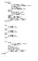
【図10】図10は、図9に続くDTDの一例を示す説明図である。
【図11】図11は、図9に示す例での要項IIのxmlデータの一例を示す説明図である。
【図12】図12は、図9及び図10に示す例での要項Iのxmlデータの一例を示す説明図である。
【図13】図13は、図12に続くxmlデータの一例を示す説明図である。
【図14】図14は、GUI定義によるユーザービューの構成と図11及び図12に示すxmlデータに対応した要項Iデータの内、組織区画の連絡先、従業員、役員等、及び経理担当者の各テーブルの表示例を示す説明図である。
【図15】図15は、要項Iデータの内、組織区画の当行出身者、資本及び大株主(大口出資者)の各テーブルの表示例を示す説明図である。
【図16】図16は、要項Iデータの内、組織区画の事業施設及び関連融資先名寄せの各テーブルの表示例を示す説明図である。
【図17】図17は、要項Iデータの内、組織区画のその他関連先、会計事務所、当行関連会社利用状況及び有価証券保有状況の各テーブルの表示例を示す説明図である。
【図18】図18は、要項Iデータの内、事業区画の平均月商、事業内容、特記事項、業界の地位、製商品及び資金決済の各テーブルの表示例を示す説明図である。
【図19】図19は、要項Iデータの内、事業区画の製商品、販売先及び仕入先の各テーブルの表示例を示す説明図である。
【図20】図20は、要項Iデータの内、事業区画の仕入先及びホームページの各テーブルの表示例を示す説明図である。
【図21】図21は、従属関係コードのコード体系の一例を示す説明図である。
【図22】図22は、表示モード変遷の一例を示す説明図である。
【図23】図23は、ボタンと処理内容等の関係を示す説明図である。
【図24】図24は、ユーザーのログインから端末への要項データの表示までの概要を示すフローチャートである。
【図25】図25は、ユーザーの権限とアクセス可能な表示モード等との関係を示す説明図である。
【図26】図26は、ユーザーの権限を判定する処理例を示すフローチャートである。
【図27】図27は、ロック可否判定処理及びロック取得処理の一例を示すフローチャートである。
【図28】図28は、ロック解放処理の一例を示すフローチャートである。
【図29】図29は要項IIでの編集モードの一例を示す説明図である。
【図30】図30は要項IIでの登録後の一例を示す説明図である。
【図31】図31は分析制御部を備えた構成例を示すブロック図である。
【図32】分析制御部によって生成される相関図の一例を示す説明図である。
【図33】相関図生成機能の処理内容の一例を示すフローチャートである。
【符号の説明】
1 端末
2 ネットワーク
3 データ格納部
4 取引先要項システム
6 取得制御部
8 表示編集制御部
10 格納制御部
16 主要動向区分管理部[0001]
BACKGROUND OF THE INVENTION
The present invention relates to a supplier requirement system, and more particularly to a supplier requirement system that handles character information related to a supplier.
[0002]
[Prior art]
Conventionally, in order to aggregate and manage information on customers and prospects (hereinafter referred to as business partners) in organizations of various types of business, manuals for business partners, business diaries, and customer lists are created by hand. Was. These supplier requirements are attached to the business promotion to the business partner, credit risk management of the credits to the business partner, takeover within the organization, various types of approval / circulation within the organization and approval. It was used.
[0003]
In recent years, with the development of information technology (IT), CRM (Customer Relationship Management) and the like have been introduced, and a mechanism for sharing transaction details with customers in the organization is introduced. For example, a PC (Personal Computer) is distributed to a person in charge in the organization, the PC and a server in the organization are connected via a network, and the information of the business partner is stored in a DB (Data Base) provided in the server. Store. Then, in response to a request from the Web browser of the PC, the server determines the access right of the user of the Web browser and searches for necessary data from the DB. The server converts the search result into data using HTML (Hyper Text Markup Language) or the like, and transmits the data to a Web browser on the PC. By using such a server and a PC, information about a business partner is shared between persons in charge of distributing the PC.
[0004]
RDB (Relational Data Base) is widely used as a DB that cooperates with a Web server. The RDB is a DB that creates a plurality of tables according to real-world entities and defines the relationship between the tables, and uses an SQL (Structured Query Language) statement to insert, update, search, etc. Perform data manipulation. In RDB, when handling a plurality of data for the same item (or attribute, field, column) from the point of data consistency, an upper limit number is set in advance and different item names are used, or a plurality of items may occur. Defines another table and associates it. For example, when managing group companies of business partners, there are a wide variety of business partners with 0 group companies and hundreds of business partners. To develop with RDB, a group company presence flag, a group company table, It is necessary to assign a sequence number of a group company. As described above, in the RDB, it is difficult to handle an entity in which the number of records for one item may be significantly different depending on a business partner, and its development is complicated.
[0005]
In the RDB, normalization is performed in order to perform a reliable search and avoid inconsistencies in data. In order to perform normalization, an item to be a key of the table is set as an essential input item, and when there are a plurality of the same item, a sequence number or the like is given. If the number of arbitrary input items is increased and the degree of freedom of input is increased, it becomes difficult to execute an accurate and reliable search. Therefore, it has been difficult to increase the degree of freedom by reducing the required input items and to improve the workability and usability at the time of user input.
[0006]
In addition, simple memos and comments on information on business partners and their officers were easy to manage when handwritten, and it was easy to convey the situation. It is difficult to construct a system that realizes the same ease of use as handwriting, because it is necessary to decide in advance whether or not it will occur, or simply to use remarks.
[0007]
Further, in the RDB, in order to increase the use efficiency of a data storage unit such as a hard disk and to improve the search efficiency, it is necessary to predetermine the data type and data length for all items. Therefore, there has been a certain limit to flexibly handle character information such as comments in the RDB.
[0008]
On the other hand, in order to share the description contents in the handwritten supplier guidelines etc. within the organization, it is necessary to copy and mail them with a copying machine or the like. In addition, in order to grasp the latest state of business partners, it is necessary to recreate business partners and the like at regular intervals. In other words, since the titles of business partners, manufactured products, and the like change, it is necessary to rewrite this part. However, at the time of renewal, in order to fill in a new form, useless work such as copying items that have not changed occurs. In addition, at the time of this renewal, there is a risk that the information content may change or be missed due to a mistake in posting by the person in charge at that time, and therefore this renewal work will be a heavy burden on paperwork including confirmation work. It was.
[0009]
In addition, in the handwritten supplier guidelines, it is necessary to duplicate almost the same contents in other forms every time a business diary, various discussions, credit risk management, etc. are performed, which increases the administrative burden. When there are a large number of handwritten forms, it is cumbersome to manage which form is to be written and where the form is currently located, and in order to know the contents already described, the investigation is performed again.
[0010]
In addition, in the handwritten supplier guidelines, there is a case where the information is not necessarily uniform and uniform because of the skill level and personality when expressing the situation of the supplier. Therefore, it is difficult to use a business partner form in order to extract a business partner with a certain situation or attribute, and when there are a large number of business partners, there is a certain situation from a paper form. Since it takes a lot of labor to extract the suppliers in the field, there is a limit to its use. Therefore, it has been difficult to share the contents described in the supplier guidelines with the organization.
[0011]
[Problems to be solved by the invention]
It is conceivable to use information of contents to be described as a supplier guideline by creating a database and systematizing this supplier guideline. However, since there are various types and forms of suppliers, it is difficult to systematically handle abundant information similar to handwriting. In addition, when dealing with information such as the sales history of the product, the organization, business, and trend of the business partner, there are a lot of text information and there are entities and items that are not input depending on the business partner. In addition, if the corporate personality (hereinafter referred to as the personality) of a business partner such as a corporation or business person is different, the items handled will change, so modeling with RDB complicates entity relationships, and system development and operation And management cost will become large.
[0012]
In addition, for systematization of supplier requirements, it is desirable to have a mechanism that enables good extraction (horizontal search) of suppliers that correspond to the status, attributes, or characteristics of suppliers. If it can be described arbitrarily, the accuracy of the horizontal search will be reduced.
[0013]
Moreover, it is necessary to deal with the point that the update frequency of information related to suppliers differs depending on each supplier and item. And when referring to information related to business partners on a terminal such as a PC, it is difficult to grasp the freshness of the information at what point in time and the information is still valid. Handling is required. However, when the content of an item is updated, it is difficult to automatically handle which range of data is confirmed as the latest by updating the item.
[0014]
Furthermore, when referring to information related to a business partner on a terminal, it is difficult to intuitively inform the user whether the data is in the middle of a work workflow or approved data.
[0015]
And the burden of office processing due to duplicate handwriting in a form cannot be improved by simply systematizing individual tasks. In other words, if work such as inputting and registering the same contents in each system is generated, the burden of paperwork due to duplicate descriptions will not be reduced as a result.
[0016]
Conventionally, when supplier requirements are renewed at regular intervals, the person in charge memorized and reviewed the customer's situation more strongly as a result of this rewriting work. Systematization of supplier guidelines only refers to items other than the changes, and there is a possibility that the degree of understanding of the situation of the supplier by the person in charge may be reduced compared to the case of copying by handwriting and renewal at the time of renewal Can also be assumed.
[0017]
In this way, in systematization of supplier guidelines that were done by handwriting, firstly, the relationship with other systems was organized,2In addition, we strive to achieve both the flexible handling of character data and the maintenance of lateral search accuracy.3In addition, it is desirable to have a mechanism for maintaining and improving the skills of the person in charge.
In particular, the present invention is to make the supplier summary system according to the present invention a top-level DB among a plurality of systems that handle trend comment data, which is character data about major trends in time series for suppliers. Consider the features you need, andSearch from other systemsThe problem to be solved is to accumulate trend comment data such as maintaining the accuracy of horizontal search so that it can be used effectively.
[0018]
The present invention provides a supplier requirements system capable of effectively utilizing data relating to a business partner stored while maintaining a flexible linkage with character data relating to a business partner and other systems. Objective.
The present invention is particularly useful for trend comment data in a state that is highly available to users and other systems, that is, to clarify reporting and handover, etc. Accumulating data on new business partnersThat is the purpose.
[0019]
In the present invention, as a premise of the invention,Handle character dataWith terminals and other systemsOver the networkConnected servers and data processed by this serverAs XML data including the character dataAnd a data storage unit for storing. AndThe data storage unit includes a DTD that is a tag system definition file that defines an XML system and tags for hierarchizing the data items, a GUI definition file that defines a display area and an input area in the terminal, Tagged data tagged according to DTD is stored as XML data including the character data, and an XML data DB retrieved from the server and the other system is provided.
Furthermore, the server displays the character data in the display area of the terminal by transmitting the data to the terminal.
The server, on the other hand, receives data entered, selected or edited by the user of the terminal in the input area of the terminal, tags the data as defined by the DTD, and validates the validity by the XML parser. A verification process is performed, and the XML data subjected to the verification process is stored in the data storage unit. Also,The serverSearch from the other system is permitted.
Further, as a feature of the present invention, the tag system definition file includes a CIF number as an element of the DTD according to the tag system definition for the XML data, and an occurrence frequency of one or more times in parallel with the CIF number. With emerging customer trends.
The customer trend has a main trend category name that appears once and a trend comment data that appears 0 times or once, and the CIF number is data that uniquely identifies the customer, The trend comment data is the character data, and is character data that is a text that is input or edited by a user of the terminal indicating a main trend of the business partner, and the main trend category name is the character data It is character data belonging to a predetermined classification type that is preliminarily classified in advance with respect to the user's terminal user.
Also,In accordance with the GUI definition file, the server displays, as the display area, a transaction for displaying the data in the items of the main trend category name and the trend comment data for each business partner specified by the CIF number. A future trend table area is displayed on the terminal.
In addition, the serverSupplier trend table, display editing control unit, mainIt has a trend category management unit and a storage control unit.
The supplier trend table has the main trend category name and the trend comment data as data to be displayed in the supplier trend table area, or as data input, selected or edited in the input area. .
The main trend category management unit manages the category type to which each major trend category belongs by storing, for each category type, the range of the main trend category code specifying the main trend category name.
The display editing control unit fetches the XML data from the XML data file when displaying the data in the customer trend table area of the terminal, and stores the XML data according to a tag of the XML data. And the edited supplier trend table is displayed in the supplier trend table area of the terminal.
When the user of the terminal inputs trend comment data in the input area, the user is allowed to select the main trend category name from the list of the main trend category names. When the main trend category name and trend comment data are input, selected or edited in the input area of the terminal, the data is received and edited in the supplier trend table.
When storing the data of the supplier trend table, the storage control unit attaches a tag corresponding to each item to each data of the supplier trend table, and data relating to the supplier trend for each CIF number Is verified by the XML parser to determine whether the data is valid in relation to the tag system definition. By storing, the XML data in which the main trend category name appears only once for each supplier trend is stored in the XML data file,
The server stores the XML data file in the database that allows the search from the other system using the main trend category name or the main trend category code for the trend comment data as an interface with the other system. Control sharing of trend comment data with other systems, Is adopted. Thus, the above-described problem is to be solved.
[0020]
The present invention employs XML technology in order to increase the availability of trend comment data, and accumulates trend comment data with tags as trend comment data. Furthermore, the trend comment data has a category of trend comment data selected from the list by the user in the same hierarchy as the trend comment data, and if there is trend comment data, the fact that the major trend category name exists is XML. Store after verifying with parser. Then, by using this main trend category name (or code) as an interface related to trend comment data, search from other systems is permitted to accumulate in a state where the availability of character data related to supplier trends is enhanced.Accordingly, the supplier guideline system according to the present invention isTrendsIt is positioned as the highest-level DB of character data regarding. That is, according to the present invention,By DTDStructured dataThe endIt can be displayed at the end or sent to another system. “Transmission” to another system is a process for permitting another system to access (search) the data storage unit according to the present invention.Is.
[0021]
In the first embodiment, a main trend classification code that explicitly classifies contents is used for a trend comment that expresses a main trend of a business partner in text (for example, FIG. 3). By using this main trend classification code as a protocol or interface between another system and the acquisition control unit, it is possible to clarify the aggregation and structuring of trend comments and improve the accuracy of lateral search. In addition, by using the group (type) of the main trend category, for example, it has a function to extract and display only the trend comments with the main trend category code of the risk management category, so that the user can record the history and attention of the business partner. It is possible to instantly grasp the points to be performed. In addition, by carefully selecting the main trend categories and disabling the input of trends that are not classified into the main trend categories, the granularity of the trends to be described is constant regardless of the person in charge, and the main trend categories are always used. This makes clear the selection of important trends to be registered among various trends of business partners.
[0022]
In the second embodiment, the essential data is XML data, and various functions relating to display editing are provided, so that data can be input and referenced with the same degree of freedom as in handwriting. In addition, basic character data related to business partners is imported from other systems, and essential items that maintain a systematic structure are automatically acquired, and the positioning of each item is simplified and clarified by the hierarchical data structure using XML. By supporting the input of character data while encouraging the user to understand, flexible handling of character data and maintaining the accuracy of horizontal search are achieved at the same time. Furthermore, the accuracy of the horizontal search is improved while facilitating the input by organizing codes indicating the relationship with the corporation or the individual having a relationship with the position or the business partner.
[0023]
DETAILED DESCRIPTION OF THE INVENTION
<First Embodiment>
FIG. 1 is a block diagram illustrating a configuration example according to the first embodiment. As shown in FIG. 1, a
[0024]
The server further stores character data automatically acquired from another system by the
[0025]
The
[0026]
The
[0027]
When using the business partner system according to the present embodiment in a financial institution, as shown in FIG. 2, other systems include an
[0028]
The
[0029]
The display
[0030]
The
[0031]
The
[0032]
FIG. 2 is an explanatory diagram showing an example of cooperation between another supplier system and a supplier guideline system when the supplier guideline system is used in a financial institution. The
[0033]
The
[0034]
The
[0035]
The self-assessment system evaluates assets such as loans from the viewpoint of credit risk management. Self-assessment is conducted twice a year in accordance with the bank closing date, and is classified into obligor categories such as normal, sensitive, and bankrupt depending on the obligor's situation, and the receivables are classified from class I. Classify by IV classification. Based on this classification, etc., allowance for doubtful accounts is calculated and the bank's asset status is reflected in the account settlement. In the work of classifying the debtors, the business type of the business partner, the position in the industry, the monthly sales for each product manufactured, etc. are also considered. For this reason, the industry code and average monthly quotient acquired from the
[0036]
With regard to this self-assessment, the applicant has developed an
[0037]
The
[0038]
The sales diary system is a system for managing a sales promotion workflow such as a person in charge at a sales office reporting a business situation. The business diary system may manage sales, response to DM shipment, etc. in cooperation with project management, loan appraisal system, and the like. In this case, the progress of the business promotion is managed by the business diary system, etc., and any comments that have been made or not made as a result of the business promotion are commented on trends depending on the importance of the business promotion. May be automatically registered in the supplier's guidelines.
[0039]
In this way, the
[0040]
When important character data is collected in the supplier's guideline system, it is possible to prevent the information from being lost and to refer to it at any time by operating a terminal such as a PC in order to confirm the contents. That is, by using the supplier requirements system, detailed work results in each system can be referred to as a list, and consistency with data of other systems can be maintained while preventing duplicate registration.
[0041]
As a business, it is possible to maintain the homogeneity and accuracy of comment information by establishing a consistent and stable business process of registering conclusions based on the workflows of other systems, and the systematic structure of essential data. As a part of the system and the mechanism that clearly shows the basis of the character data, it becomes easy to access the basis of the character data, and the
[0042]
Referring to FIG. 1 again, the
[0043]
FIG. 3 shows examples of main trend category codes and major trend category names when used in financial institutions. In the example shown in FIG. 3, when trend comments are input according to the control of the display
[0044]
The main trend
[0045]
FIG. 4 shows a GUI and an example of contents of a supplier system for handling trend comments. In the following, examples of screens and business partners will be disclosed for explanation, but the contents are virtual examples and are irrelevant to actual corporations and individuals.
[0046]
In the example shown in FIG. 4, transaction details handled by the supplier requirement system are displayed in the supplier trend table 100. The supplier trend table 100 has a plurality of supplier trend records (one line in the table) as a list display. The supplier trend record includes the date of occurrence, main trend category, and details (trend comment). ), Entry date, and entry person. In the example shown in FIG. 4, the display
[0047]
In the example shown in FIG. 4, the date of occurrence of the loan transaction is October 1, 1960, and the trend of the business partner before the start of the transaction is registered on the same day. In the entry field, the store number and full name are displayed, but are omitted in the figure. Since then, only important matters defined for major trends such as receiver / account receivable accidents and establishment of business facilities have been registered. “Recipient” is a bill of exchange. In October 1970, there was a transfer, which is a change of the dealer. At this time, the entrants changed from the person in charge at the Nagano branch to the person in charge at the head office sales department. After that, the company was listed and established a subsidiary. The trend comment regarding the poor performance can be automatically acquired from the
[0048]
Further, as shown in FIG. 1, the main trend
[0049]
In a preferred example, the main trend
[0050]
FIG. 5 is an explanatory diagram illustrating an example of a trend comment type display. Among the customer trend records shown in FIG. 4, there are two records to which the main trend category belonging to the risk management type is attached, that is, a receiver / account receivable accident and poor performance. The user compares the display of only this risk management type (management item) with the display of all indications, and grasps the trends of business partners in a short time and accurately by performing a detailed examination of the risk management items. be able to.
[0051]
In order to display only the management items, in the example shown in FIG. 3, a supplier trend record having a main trend category code of 10,000 or more and less than 20,000 is extracted. FIG. 6 is a flowchart illustrating an example of trend comment type display control. First, the trend comment group of the said customer stored in the
[0052]
Steps S4 to S8 are repeated to extract all supplier records in the main trend category belonging to the extraction range set in the extraction range setting steps S2 and S3 (intra-range trend comment extraction step). Subsequently, the supplier trend record that is the type display target is displayed on the terminal 1 (step S9, extraction display control step).
[0053]
The configuration shown in FIG. 1 and the processing shown in FIG. 6 and the like can be realized by the CPU of the server executing a predetermined program. The server of the supplier summary system and the CPU (not shown) of the terminal perform various calculations according to a predetermined program (command). The CPU displays character data or the like on the screen of the
[0054]
Particularly in the present embodiment, the supplier trend display program includes the following commands.
A supplier identification command for specifying the supplier trend record group stored in the
An extraction range setting command for acquiring the type or attribute of the main trend category displayed on the
An in-range trend comment extraction command for extracting a supplier trend record of a main trend category belonging to the extraction range set according to this extraction range setting command.
An extraction display control command for causing the terminal to display a supplier trend record group extracted according to the in-range supplier trend record extraction command.
[0055]
This supplier trend display program is stored in a
[0056]
When referring to a program as an instruction to operate the CPU, an instruction to operate the CPU only with each instruction and an instruction to operate the CPU depending on other programs such as an operating system stored in advance in the program storage unit Or both. Here, “operating system” is interpreted broadly. Includes transaction manager, database manager, execution environment, etc.
[0057]
In the example of accumulating trend comments relating to business promotion, a main trend category corresponding to the transaction history type of the main trend category may be added. In a preferred example, when trend comments relating to sales promotion are stored in relation to other types of trend comments, it is possible to generate supplier trends that are easy to register and reference and are easy to understand. In this example, the main trend
[0058]
In a preferred example, the main trend
[0059]
FIG. 7 is an explanatory diagram illustrating an example in which a trend comment of a sales promotion type is associated with a main trend category of another type. In the example shown in FIG. 7, the trend of business partners, the contents and results of business promotion are described in the detailed comments. Then, between the detailed comment and the date of entry, the contract or non-contract of the result of business promotion is displayed. For example, at the start of the Bank's loan transaction on October 1, 1960, it was closed. At this time, a comment is written: “A bank fund transaction will be a parallel transaction due to the start of this bank transaction. On October 1, 1965, a new person in charge at the dealership promoted the business, and the construction of the plant and capital investment of 100 million yen were concluded (
[0060]
In the example shown in FIG. 3 and the like, the main trend categories for classifying trend comments have a hierarchical structure of a plurality of types and categories belonging to various types. In addition, when sub-partitions are used, there are three layers. This hierarchical handling can systematize the importance of customer trends. On the other hand, in the hierarchical structure, there is a case where one item wants to temporarily belong to another item. Further, if links regarding the grounds and relations of each item can be attached, the relationship with work result files and the like in other systems can be handled systematically. In such an example, as shown in FIG. 1, the main trend category belongs to the main trend category in which the main trend
[0061]
The category tree
[0062]
Second Embodiment
In the second embodiment, an example will be described in which a supplier requirement system is constructed using a structured markup language (ML) such as XML (eXtensible Markup Language). XML is a document description format derived from SGML (Standard Generalized Markup Language), which simplifies SGML and is adapted for use on the Internet. In XML, by defining a document type definition (DTD), a tag system (tag set) corresponding to the use of data is used. By using the tag system, document types of elements and attributes can be defined. XML data is a text file that indicates the structure of a document with tags defined by DTD. Since XML is based on SGML, it is suitable for processing non-standard documents such as books and Web pages. For example, the length of data included in one item cannot be determined in advance, and it is difficult to manage a document in which the number of items changes with the RDB, but XML data is tagged text data. Therefore, character information can be handled flexibly.
[0063]
The tag system indicating the structure of the XML document is a hierarchical type. The hierarchical type is, for example, a tree structure in which an element of an organism includes animals, plants, and microorganisms, and an element of an animal includes species such as mammals and reptiles. The tree structure is useful for humans to understand the semantic content of the elements. On the other hand, the tree structure is easy for a computer in that data can be manipulated by accessing a parent-child relationship in which elements are nodes. XML data, which is a set of character data clearly defined in a hierarchical structure, is used not only for page markup but also for describing meta contents for managing various properties, exchanging data with RDB, and messaging can do. That is, a tag indicating the structure of a document is used for specifying an expression format on a page or the like, an attribute specification in a character data system as an element, or a correspondence with an item in an RDB table.
[0064]
In the DTD that defines the tag system, the data type of elements is only character data. An XML document that correctly follows the specified DTD is said to be valid. A valid XML document conforms to the element name, hierarchy, order, and number of appearances such as whether the element is essential or optional as defined in the DTD.
[0065]
A software module that handles XML data is called an XML parser (XML processor). The XML parser parses the XML data and verifies the validity. The XML data whose validity has been verified follows a predetermined tag system. Examples of API (Application Programming Interface) for accessing the internal structure of XML data include DOM (Document Object Model) and SAX (Simple API for XML). DOM expresses XML data as a tree (DOM tree) composed of nodes of elements and character data. A valid XML data DOM tree follows the hierarchical definition by DTD. The DOM API is suitable for processing that sorts the elements of an XML document in a certain order, moves them to another place, or inserts new elements.
[0066]
XML is often used by Web applications that realize certain functions while transmitting and receiving data and programs between a server and a terminal. For this reason, XML parsers or the like having a function for verifying validity are object-oriented. Many have been developed for the Java language (registered trademark). In the Java development / execution environment, class hierarchies have already been defined, and by utilizing interfaces (also called protocols in other languages) without multiple inheritance, programs called modules and components Increases reusability and independence of parts. In a Java development environment, an existing module can be used for XML validation. In Web application development, particularly J2EE (
[0067]
In J2EE, the terminal often uses a Web browser or a Java application equipped with a GUI. When using a Java application, it is easy to define a GUI by using Swing as a GUI or a screen design tool using the same. The EJB maintains a session with the Java application of the
[0068]
Various methods have been proposed for storing XML data in a database. Mapping XML tags to RDB tables and storing them in RDB, storing XML data as huge text data, generating search indexes as side tables, and class hierarchy in object-oriented databases For example, a method of mapping XML data.
[0069]
In XML data operations, instead of using a DOM tree, the schema definition of complex records is performed, and XML data tags, Java objects, and database records can be converted to each other at any time. An execution environment is also provided. In addition, XML Schema is defined as a technique for making document type definition easier to use in XML-related technology. When XML Schema is used, the data type and the like can be verified by validating the XML data.
[0070]
In the present embodiment, a database that stores DTD, DOM tree, and XML data as text and can be searched by SQL using a side table, EJB by J2EE, GUI by Swing, applet executed by Web browser, It uses techniques such as type checking using EJB, servlets, and applets, display editing control, and data fetching from other systems using RDB. Instead of DTD, DOM tree, SQL search, applet, and Web browser, XML Schema, complex record, XQuery, a combination of Web browser and XSLT may be used. When the terminal is a portable terminal such as a PDA or a mobile phone, for example, in order to provide only a display, XML data may be converted into HTML by XSLT and transmitted.
[0071]
FIG. 8 is a block diagram illustrating a configuration example of the second embodiment. A supplier system according to the present embodiment includes a tag
[0072]
The tag
[0073]
In the example shown in FIG. 8, the server captures from the
[0074]
The display
[0075]
The display
[0076]
In addition, the display
[0077]
The
[0078]
The
[0079]
In a preferred example, the display
[0080]
In the present embodiment, the display
[0081]
FIG. 9 is an explanatory diagram showing an example of a DTD used in the present embodiment. The description of DTD is by SGML. yoko2.dtd is the DTD of supplier requirements II. The element (ELEMENT) of supplier essential point II has a CIF number and a supplier trend. The + at the end of the supplier trend indicates that this element appears one or more times. If nothing is added at the end, it must be specified once.? Is 0 or 1 and * is 0 or more. No end and + are required items, and + and * can be written repeatedly on XML. ? And * may not appear. For this reason, the essential item II data is generated when one supplier trend is input for the supplier of the CIF number. The supplier trend may be entered repeatedly.
[0082]
The supplier trend includes the date of occurrence, major trend category code, major trend category name, detailed comment, date of entry, store name, store name, store user ID, and store name. The detailed comment is a trend comment, and if the main trend category and the date of occurrence are entered, the essential point II data is registered even if no comment exists. An example of the essential item II data by this DTD is shown in FIG.
[0083]
yoko1.dtd is the definition of supplier requirements I. As the basic attribute, the industry code and the industry name are enclosed in parentheses in order to specify that the industry name is also required when the industry code is input. Since? Is added outside the parentheses, the number of appearances of the set of industry code and industry name is designated 0 times or once. As a customer, the base date, basic attributes, etc. are defined. This customer stores the data of the
[0084]
In the example shown in the figure, the tag is written in full-width Japanese for ease of understanding, but the software and programs are easy to handle alphabets and numbers, so in fact, English notation or Japanese Roman notation is used. Use it.
[0085]
In a preferred example, when the
[0086]
In addition, when a supplier requirement is attached as a basis for self-assessment, since the supplier requirement at the time of the assessment is required, the history
[0087]
Referring to FIG. 11, the CIF number and the date of occurrence are a fixed-length numeric string without a break. In this embodiment, the XML data does not include a hyphen or the like, and a hyphen is inserted in the GUI definition as a kind of display data type. In yoko2.dtd, the supplier requirements have a unique CIF number and one or more supplier trends in parallel. Specification of document type by tag starts with <tag name> and ends with </ tag name>. This tag is defined by overlapping according to the hierarchy. For example, the main trend classification code belongs to the supplier trend, and the supplier trend belongs to the supplier guideline II. This hierarchy can be managed by a DOM tree having a tree structure. The relationship between the main trend category codes and the main trend category names is as shown in FIG.
[0088]
Referring to FIG. 12, the XML data of the supplier requirement I is updated after the CIF number. This order is the order in parentheses that defines the child element of the element of the supplier requirement I in FIG. The customer following the renewal is omitted here. The title subordinate relationship codes and the names of officers and the like are a list of relationships between the Company (business partners) and officers in advance, and FIG. 21 shows an example. For representatives, etc., the representative right presence /
[0089]
FIG. 14 to FIG. 20 are explanatory diagrams illustrating examples of screens of supplier requirements I. In the essential point I, two sections (pages) of an organization and a business are defined, and transitions are made by tabs. As the contents of the essential I data, the organization section that displays the contents of the organization, contact information, shop name, number of employees, officers, etc., accounting staff, bankers, capital, major shareholders (large investors), business facilities, related It has tables for loan name identification, other related parties, accounting offices, bank affiliated company usage status, and securities holding status. The business section for displaying the business content includes tables of average monthly sales, business content, manufactured products, special notes, fund settlement, sales destination, supplier, and homepage address. The special notes are comments on the business contents and the characteristics of the manufactured products, and comments on the status of the industry.
In the example shown in FIG. 14 and the like, the items that can be input and the entire update date are February 10, 2002, and the update date of data acquired from the
[0090]
The DTD hierarchy and the screen display hierarchy are different. The element definition of DTD is not a semantic content system, but collects data acquired from the RDB as a customer, and collects data related to an input customer as a customer or the like. The DOM tree is generated at the DTD hierarchy. In the presentation layer, that is, the display
[0091]
Since A Sangyo Co., Ltd. is a corporation, the name of the shop name cannot be entered. Fields that cannot be entered should be grayed out. Here, the upper left and lower right diagonal lines of the field (box for inputting each item) indicate that input is not possible. A black circle is added to the upper left of the CIF number field. This black circle indicates that the field is a derivation item. When you enter the CIF number of the president, such as an officer, your name and date of birth are derived. The derivation destination field is grayed out because it cannot be entered. This table of officers and the like is displayed for five records. However, when data of six or more records is registered, the sixth and subsequent contents can be referred to by operating the right slider.
[0092]
In a preferred example, the display
[0093]
In the example shown in FIG. 14, since Shiro Osaka does not have a CIF number as a managing officer or the like, his / her name is directly input. In normal RDB, it is not possible to permit entry of items in the table without inputting a key value such as a CIF number. However, in this embodiment, the data structure is XML, and each item can be arbitrary. On the other hand, when a CIF number is input, derivation can be performed. By separating the definition of the tag system based on DTD and the business logic of derivation, the CIF number can be an optional input item, and flexible handling of derivation when input can be performed.
[0094]
In a preferred example, the display
[0095]
The dependency codes shown in FIG. 21 are systematized in a certain order with the president, chairman, and vice chairman. A plurality of records for the same element of XML have no concept of sequence number or order in the DTD in the present embodiment. In the present embodiment, positions such as officers are coded, and the numbers of the dependency relationship codes are given in the order to be displayed. The arrangement of records of officers and the like (a plurality of identical elements in the XML data) is arranged in ascending order of dependency code. That is, in the present embodiment, the display
[0096]
In the example shown in FIG. 21, the dependency relationship codes are flagged with corporations, individuals, and positions. Thereby, it is possible to have separate code systems for the subordinate relationship in the case of a corporation, the subordinate relationship in the case of an individual business owner, and the case of a position subordinate relationship. In this example, the display
[0097]
In the example shown in FIG. 15, the shareholding ratio is derived from the total and the number of shares held by each shareholder, with the number of shares held by the major shareholders (large investors) as the derivation source. This derivation is performed by EJB. In the example illustrated in FIG. 16, name management of related loan destinations is performed. At this time, the dependency code is used in relation to the Company. Since A Sangyo Co., Ltd. is a corporation, this relation is selected from the subordinate relation codes in which the corporation flag is 1 among the subordinate relations shown in FIG. Related loan name identification (group name identification) is useful for managing credit risk, ascertaining the details of guarantees, and identifying parties that are substantially the same. Particularly in this embodiment, since the correlation is organized using the dependency relationship code, the accuracy of credit risk management for the entire group can be improved. In addition, if the relationship between the Company and A Opto Device is a subsidiary, the A Op Device related lender can automatically add the opposite concept of the subsidiary to the A industry.
[0098]
The other related parties shown in FIG. 17 are, for example, companies that have no business with the Bank but are related to the Company. The Company's shares owned by the Bank in the case of securities holdings are cases where the entity using the supplier's requirements system owns the shares of the counterparty, and vice versa.
[0099]
In the business section shown in FIG. 18 and FIG. 19, the composition ratio of the business content is derived from the business content, the average monthly quotient for each business content, and the average monthly quotient total. For example, when the payment is made on the payment deadline, the payment is closed on the last day of the current month, and the payment is made on the 15th of the following month. The reason why there are two columns is that there are two settlement months in cases where the payment date differs depending on the counterparty or where the settlement is made twice a year (six months settlement). In the fund settlement in FIG. 10, the
[0100]
19 and 20, the CIF number is an optional input item, and when it is input, it is used as a derivation source for the name, address, loan number, and the like. The main transaction store is derived from the loan number. The display
[0101]
FIG. 22 is an explanatory diagram showing an example of display mode transition. As shown in FIG. 22, the display
[0102]
When the user logs in to the supplier requirement system or the loan support system including the same, the user inputs the CIF number and selects the requirement I or II. FIG. 23 is an explanatory diagram showing the relationship between the edit button to be displayed in each edit mode and the processing contents when an event of pressing the button is received. For example, select item I and press the open button. Then, a transition is made to the reference mode of item I. In the reference mode, a return button for transitioning to the selection screen, a point II button for transitioning to the reference mode of the point II, and an editing button for transitioning to the edit mode are handled. The edit button is displayed only when the user has editing authority, and the item II button is also displayed only when the user has the reference authority of item II. In the edit mode, gray-out is canceled for fields that can be input, enabling input and editing. When the back button is pressed, the edited content is discarded and the screen shifts to the item selection screen. When the registration button is pressed down in the edit mode, sorting is performed, and a transition is made to a confirmation mode in which the edited content is displayed on the screen in an uneditable state. In the confirmation mode, an inquiry is made as to whether or not registration is possible. When the Yes button is pressed, after confirmation in a confirmation dialog box or the like, the entire item I data including the editing result is updated to the XML data DB. When the undo button is pressed, the editing mode is restored while maintaining the editing result so far. When the transition is made between the requirement selection screen, the requirement I, and the requirement II, the CIF number already input is taken over. Accordingly, when the point I is referred to and the point II button is pressed down, the reference point II of the same supplier is referred to.
[0103]
In the example shown in FIG. 14 and the like, there is a delete check box at the left end of each table. When the record to be deleted is selected in the edit mode and the check box is turned on, when the registration button is pushed down and the mode is changed to the confirmation mode, the display
[0104]
FIG. 24 is a flowchart showing an outline from user login to display of essential data on the terminal. The supplier requirement system identifies the worker who has logged into the supplier requirement system based on the user ID (step S11). The user inputs the CIF number, selects item I or II, and depresses the open button (step S12). The authority to refer to the supplier requirements is confirmed from the user ID or the like (step S13). If there is an authority, data such as the basic attributes of the supplier is acquired from the
[0105]
In the example of controlling whether or not editing is possible according to the authority of the user, the display
[0106]
In the example in which the access control shown in FIG. 25 is performed, the display
[0107]
FIG. 26 is a flowchart illustrating an example of processing for determining user authority. When the supplier requirement system identifies the worker who has successfully logged in (step S21), it subsequently checks whether or not the supplier has a loanee number (step S23). Since the supplier requirements system accumulates information on suppliers who have loanee numbers that can specify dealer information, suppliers who do not have loanee numbers are not subject to the preparation of the guidelines. . The store information includes a store number or the like that identifies one or a plurality of business stores (transaction stores) that conduct business with the business partner. Further, in the case of accumulating information on a destination with no transaction record such as a prospective customer, a loanee number is assigned to the prospective customer or this step S23 is reviewed. Subsequently, the store to which the user belongs is confirmed (step S24). If you are a headquarters user, you can only refer to it. On the other hand, in the case of a store, first, it is confirmed whether the selection of the essential item is I or II (step S25). In the case of the essential item I, when the store number of the user belongs and the store number of the customer's transaction store match, the edit button is displayed (step S27), the reference and the edit are permitted, and the reference mode screen of the essential item I is changed. To do. Under this condition, since reference and editing of the essential point II are permitted at the same time, the basic item II button is also displayed. On the other hand, in the case of inconsistency, since it is another store, only reference is permitted while editing is not allowed. In this case, the reference item II button is not displayed because reference to the item I is not permitted.
[0108]
In the case of the essential point II, it is confirmed in step S28 whether or not it is another store, and if it is another store, reference is also impossible. Therefore, the transition from the supplier requirement selection screen to the requirement II screen is not performed. On the other hand, if the user's affiliation is a main store or a store with multiple store transactions, an edit button is displayed (step S29), reference and editing are permitted, and a transition is made to the reference mode screen of item II. . Under this condition, the reference I button is also displayed because reference and editing of the guideline I are permitted at the same time.
[0109]
Next, a lock for preventing data inconsistency due to multiple writing to the XML data DB or the like will be described. In this example, the server permits simultaneous multiple references by a plurality of users for the same business partner, and performs exclusive control in edit mode so that a plurality of users do not enter the edit mode for the same business partner at the same time. A lock control unit 94 is provided. As shown in FIG. 22 and the like, in this embodiment, reference and editing are clearly separated. Even if many users refer to it at the same time, there is no need to lock it because writing is not performed. On the other hand, if one user transitions to the edit mode and then allows other users to edit, double writing occurs and one update is discarded. For this reason, in this embodiment, while permitting multiple access for reference, the edit mode is registered in the confirmation mode or locked in units of CIF numbers until editing is interrupted by returning to the selection screen. It was.
Since the edit mode is clearly defined and all edits such as addition, update, and change are disabled at the time of reference, exclusive control can be performed when transitioning to the edit mode and at the time of registration after completion of editing. In this embodiment, by handling the access from the other system to the
[0110]
Further, in a Web application using J2EE or the like, it can be assumed that a terminal such as a PC crashes, the session with the terminal is forcibly disconnected, and only the state where the lock is secured remains in the server.
[0111]
In the example illustrated in FIG. 8, the lock control unit includes a lock acquisition control function 96, a lock
[0112]
The lock availability determination function 98 indicates that the lock end time of the lock management information identified by the CIF number of the business partner to be determined for lock is later than the current time, and the user ID in the lock management information is If they are different, it is determined that the lock has been acquired.
[0113]
Specifically, as shown in FIG. 27, when the lock acquisition control function 96 shifts to the edit mode (step S41), the lock is acquired by the other users in the main item data of the supplier of the CIF number. It is determined based on the lock management information (step S42). If the lock has not been acquired, after confirming that there is no own lock management information (step S43), the lock management information is written (step S44). If there is own lock management information, the end time of the lock information is updated (step S45).
[0114]
If there is a locked user in step S42, the user IDs in the lock management information are compared to confirm whether or not the user is himself. If the terminal is forcibly terminated and the edit button is pushed down after the restart and before the lock end time, the terminal is locked. If it is own lock, the lock information is updated (step S50), the XML data is locked, and the edit mode is started.
[0115]
Following step S44 or S45, the lock information is checked again, and it is determined whether there is another user who has written the lock information at the same timing. When the other party reads the lock information in step S42 between immediately after step S42 and the completion of step S44, there is another user. In the opposite case, there are other users who precede. If there is no other user, the lock is acquired and the mode is changed to the edit mode. On the other hand, if there is another user, the user with the earlier lock start time or the other user is selected by other methods (step S47). If another user is selected, the lock end time is updated and the lock is released (step S48). In steps S48 and S49, if another user has already acquired the lock, editing may be disabled and a message indicating that multiple access has occurred may be displayed on the terminal.
[0116]
As shown in step S28, the lock
[0117]
FIG. 29 is an explanatory diagram showing an example of the GUI of the supplier essential point II. The GUI of the essential item II displays the trend comments in a time series and the supplier trend table 100 that cannot be changed only by display, the existing trend comments in the reference mode, and the existing trend comments in the edit mode. A display / input /
[0118]
FIG.9As shown in FIG. 5, in the edit mode in the essential point II, clear, add, change, and delete buttons are arranged in the vicinity of the display / input /
[0119]
In the supplier trend table 100, records of supplier trends are sorted using the date of occurrence as a sorting key. For this reason, for example, when major trends in several years ago are identified and comments about the trends are entered, the date of occurrence is set to be several years ago, so that the date of occurrence is independent of the entry / registration order. Sorted in order. XML data is generated and stored in this rearranged state.
[0120]
Even within a branch, you may get information that should be limited to the person in charge and their supervisor. For example, information such as executing M & A on a date that is coming soon needs to be handled with care. On the other hand, at the moment of the announcement date, various actions are required. In such a case, if the date of occurrence is registered as a future date, the date is set as the ban date, and the date is displayed when the date is reached, the main points are already on the same day. And can use the information immediately within the organization. Requirement II in the supplier requirements system is for registering important business trends that have occurred in the past. As an exception to the mechanism for registering past results, a mechanism such as ban is introduced. If the display
[0121]
FIG. 31 is a block diagram illustrating an example of a supplier requirements system including an analysis control unit. In this example, the server stores a tag
[0122]
In the example shown in FIG. 31, in particular, the server extracts information related to the relationship between the business partners from the essential data stored by the
[0123]
In the example shown in FIG. 31, related items such as sales destinations are particularly useful in the tag system and GUI definition shown in FIGS. 9 and 14. That is, as the tag system, the CIF number of the subject matter itself, and the CIF number of the seller etc. when the seller and / or supplier (seller etc.) are attached, If the CIF number is not attached to the seller, etc., the name or name and address of the seller, etc., and the sales amount or purchase amount for each seller, etc. regarding sales or purchase to the seller, etc. It is good to have. Here, the CIF number is a unique number that uniquely identifies the customer and the name or name and address.
[0124]
In the example illustrated in FIG. 31, the analysis control unit 110 includes a general-purpose search function 114 that searches for a dependency relationship of a business partner in a search target range using a CIF number, a name, a name, and an address as search keys. The general search function 114 may use the
[0125]
As an example of general-purpose search in relation to sales promotion, for example, high-quality companies that do not have business with the Bank have no supplier requirements, and it is difficult to grasp the business relationship, but the above-mentioned companies are in the sales destination of the requirement I By searching for the destination, it can be used for bill discount promotion. In addition, when a certain customer has a “PC display” for a manufactured product, it is also possible to search for a destination having “PC display” data for the product name of the supplier and use it for business arrangement.
[0126]
FIG. 32 is an explanatory diagram showing an example of a correlation diagram of sales / purchase relationships of business partners. In this example, the industry A shown in FIG. In order to generate the correlation diagram as shown in FIG. 32, the analysis control unit includes a correlation
[0127]
FIG. 33 is a flowchart showing an example of correlation diagram generation processing by the correlation
[0128]
Subsequently, the correlation
[0129]
Subsequently, the extraction of the seller and the supplier is repeated through the loop of steps S86 and S87. When the extraction of the second tier (B industry,
[0130]
When the extraction of the second-tier supplier is completed, the second-tier sales destination is subsequently extracted. If industry A is stored as a supplier in the essential data I of industry B (b1, the first of buyers), it is collected in step S84. As a supplier of B industry, “b1 ss2 (
[0131]
When the correlation diagram illustrated in FIG. 32 is generated by the processing shown in FIG. 33, etc., from the relationship of the composition ratio of the average monthly sales among the business partners, the business position of the business partners and the target business partners for the sales business Can be confirmed. As shown in FIG. 32, when a correlation diagram is generated according to a distribution route centering on a certain customer, the supply chain of the manufactured product is clearly indicated, and a proposal for cost reduction can be made. Furthermore, it is possible to grasp the fund demand schedule for accounts receivable and the like based on the average monthly quotient, the composition ratio, and the payment due date and payment date information. In this case, a cash ratio or the like may be used in combination. Further, payment for sales, payment date for each payee (supplier), and the like may be handled. In this way, when paying attention to the flow of funds, the direction of the arrow in the correlation diagram is the same as the flow of funds, and is the opposite direction to the example shown in FIG. Good.
[0132]
The correlation diagram makes it clear at a glance which business partners need and how much working capital is needed, and makes it easier to carry out the contents of business promotion appropriate for the business partners considered. Further, since the same business partners are aggregated using a CIF number, a name or a name, etc., it is possible to visually grasp the actual state of the business. In addition, if the correlation diagram shown in FIG. 33 is grasped, it is possible to immediately grasp the influence or the like when the credit risk of a certain supplier suddenly increases.
[0133]
As shown in FIG. 32, the search range of the correlation diagram is a purchase / sales hierarchy in several stages from a focused business partner, a group relationship in a certain industry is extracted, and a relationship from a certain raw material to a final product is expressed. Various correlation diagrams according to various purposes, such as extraction, can be generated from data organized and stored in the supplier requirements system. For example, when there is a raw material with a large price movement, by grasping a series of distributions and correlations of business partners who use the raw material as a product, we investigate in advance the impact of changes in the surrounding situation, such as a sharp rise in raw material costs. , Credit risk management accuracy can be dramatically improved.
[0134]
Referring to FIG. 31 again, the
[0135]
In addition to the essential I and essential II data, the essential data includes the loan policy that indicates the Bank's policy regarding future loans, and the general search function 114 enables the extraction of the destinations that have a certain loan policy or more. Also good. In order to make the extraction and search by the analysis control unit 110 precise and useful, the main trend in which the display
[0136]
The display
[0137]
【The invention's effect】
The present invention according to
[0138]
[0139]
Claim3In the present invention,Because trend comment data is sorted and displayed according to the date of occurrence, it is possible to display, transmit, and store XML data that is highly visible and easy to handle in other systems while adopting XML technology. .
[Brief description of the drawings]
FIG. 1 is a block diagram illustrating a configuration example according to a first embodiment.
FIG. 2 is an explanatory diagram showing the relationship of each system regarding handling of character data.
FIG. 3 is an explanatory diagram showing an example of main trend categories;
FIG. 4 is an explanatory diagram illustrating an example of a GUI for a trend comment.
FIG. 5 is an explanatory diagram illustrating an example of a trend comment type display;
FIG. 6 is a flowchart illustrating an example of trend comment type display control;
FIG. 7 is an explanatory diagram illustrating an example in which a trend comment of a business promotion type is associated with a main trend category of another type.
FIG. 8 is a block diagram illustrating a configuration example of the second embodiment.
FIG. 9 is an explanatory diagram showing an example of a DTD used in the present embodiment.
FIG. 10 is an explanatory diagram showing an example of a DTD following FIG. 9;
FIG. 11 is an explanatory diagram showing an example of xml data of the essential point II in the example shown in FIG. 9;
FIG. 12 is an explanatory diagram illustrating an example of xml data of the essential item I in the example illustrated in FIGS. 9 and 10;
FIG. 13 is an explanatory diagram showing an example of xml data following FIG. 12;
FIG. 14 is a view of a user view based on a GUI definition and the essential section I data corresponding to the xml data shown in FIGS. 11 and 12, contact information of an organization section, employees, officers, and accounting staff It is explanatory drawing which shows the example of a display of each table of.
FIG. 15 is an explanatory diagram showing a display example of each table of the bank originator, capital, and major shareholder (major investor) of the organizational block in the essential item I data.
FIG. 16 is an explanatory diagram showing a display example of each table of the business facility of the organizational section and the related loan destination name identification in the essential item I data.
FIG. 17 is an explanatory diagram showing a display example of each table of the other related destinations of the organizational block, the accounting office, the bank affiliated company usage status, and the securities holding status in the essential item I data.
FIG. 18 is an explanatory diagram showing a display example of each table of average monthly sales of business sections, business contents, special notes, industry status, manufactured products, and funds settlement in the item I data.
FIG. 19 is an explanatory diagram showing a display example of each table of manufactured products, sales destinations, and suppliers in the business section in the essential item I data.
FIG. 20 is an explanatory diagram showing a display example of each table of the supplier and the homepage of the business section in the essential item I data.
FIG. 21 is an explanatory diagram illustrating an example of a code system of a dependency relationship code;
FIG. 22 is an explanatory diagram showing an example of display mode transition;
FIG. 23 is an explanatory diagram showing a relationship between a button and processing contents.
FIG. 24 is a flowchart showing an overview from user login to display of essential data on a terminal;
FIG. 25 is an explanatory diagram showing the relationship between user authority and accessible display modes and the like.
FIG. 26 is a flowchart illustrating an example of processing for determining user authority;
FIG. 27 is a flowchart illustrating an example of lock permission determination processing and lock acquisition processing;
FIG. 28 is a flowchart illustrating an example of lock release processing;
FIG. 29 is an explanatory diagram showing an example of an edit mode in item II.
FIG. 30 is an explanatory diagram showing an example after registration in the essential point II.
FIG. 31 is a block diagram illustrating a configuration example including an analysis control unit.
FIG. 32 is an explanatory diagram illustrating an example of a correlation diagram generated by an analysis control unit.
FIG. 33 is a flowchart illustrating an example of processing contents of a correlation diagram generation function.
[Explanation of symbols]
1 terminal
2 network
3 Data storage
4 Supplier Guidelines System
6 Acquisition control unit
8 Display editing control unit
10 Storage controller
16 Major Trend Classification Management Department
Claims (5)
Translated fromJapanese前記データ格納部が、前記データの項目を階層化するXMLの体系及びタグを定義したタグ体系定義ファイルであるDTDと、前記端末での表示領域及び入力領域を予め定めたGUI定義ファイルと、前記DTDに従ってタグ付けされたタグ付きデータを前記文字データを含むXMLデータとして格納すると共に前記サーバー及び前記他システムから検索されるXMLデータDBとを備え、
前記サーバーは、前記端末に前記データを送信することで当該端末の表示領域に当該文字データを表示し、
一方、前記端末の前記入力領域にて当該端末のユーザーによって入力、選択又は編集されたデータを受信し、当該データに前記DTDによって定義されたタグ付けをし、XMLパーサーによる妥当性の検証処理をし、当該検証処理したXMLデータを前記データ格納部に格納し、
当該サーバーが、前記他システムからの検索を許可する所定のシステムにおいて、
前記タグ体系定義ファイルは、前記XMLデータに対する前記タグ体系定義による前記DTDの要素として、
CIF番号と、このCIF番号と並列で発生頻度が1回以上出現の取引先動向とを有し、
当該取引先動向は、発生頻度が1回出現の主要動向区分名称と、0回又は1回出現の動向コメントデータとを有し、
前記CIF番号は、前記取引先を唯一に識別するデータで、
前記動向コメントデータは、前記文字データであって、前記取引先についての主要な動向を示し前記端末のユーザーによって入力又は編集される文章となった文字データで、
前記主要動向区分名称は、前記取引先の主要な動向を前記端末のユーザーに対して予め明示的に区分すると共に、予め定められた所定の区分種別に属する文字データで、
前記サーバーは、前記GUI定義ファイルに従って、前記表示領域として、前記CIF番号で特定される取引先毎に、前記主要動向区分名称と、前記動向コメントデータとの項目で当該データを表示するための取引先動向テーブル領域を前記端末に表示させ、
当該サーバーは、
取引先動向テーブルと、表示編集制御部と、主要動向区分管理部と、格納制御部とを有し、
前記取引先動向テーブルは、
前記取引先動向テーブル領域に表示するデータとして、又は、前記入力領域にて入力、選択若しくは編集されたデータとして、前記主要動向区分名称と、前記動向コメントデータとを有し、
前記主要動向区分管理部は、
前記主要動向区分名称を特定する主要動向区分コードの範囲を前記区分種別毎に記憶することで、前記各主要動向区分が属する前記区分種別を管理し、
前記表示編集制御部は、
前記データを前記端末の前記取引先動向テーブル領域に表示する際に、
前記XMLデータファイルから前記XMLデータを取り込み、当該XMLデータのタグに従って当該XMLデータを取引先動向テーブルに編集し、当該端末の前記取引先動向テーブル領域に当該編集した取引先動向テーブルを表示し、
前記端末のユーザーが前記入力領域に動向コメントデータを入力する際に、
前記主要動向区分名称を当該主要動向区分名称の一覧から当該ユーザーに選択させ、
前記端末の入力領域に主要動向区分名称及び動向コメントデータが入力、選択又は編集された際には、
当該データを受信して、前記取引先動向テーブルに編集し、
前記格納制御部は、
前記取引先動向テーブルのデータを格納する際には、
前記取引先動向テーブルの各データに前記各項目に応じたタグを付し、前記CIF番号毎の取引先動向に関するデータが前記タグ体系定義に定義された階層及び出現回数となっているかを前記XMLパーサーにより検証処理し、当該データが当該タグ体系定義との関係で妥当性を有する場合に当該処理されたXMLデータを格納することで、前記主要動向区分名称が前記取引先動向毎に1回のみ出現するXMLデータを前記XMLデータファイルに格納し、
前記サーバーが、このXMLデータファイルを、当該動向コメントデータについて当該主要動向区分名称又は主要動向区分コードを当該他システムとのインタフェースとし、前記他システムからの検索を許可する前記データベースに格納することで、当該動向コメントデータの他システムとの共有を制御することを特徴とする取引先要項システム。Comprising a connected servervia the terminal and other systems andnetworksthat handles character data, and a data storage unit for storing data to be processed by the server as XML data includingthe character data,
The data storage unit includes a DTD that is a tag system definition file that defines an XML system and tags for hierarchizing the data items, a GUI definition file that defines a display area and an input area in the terminal, An XML data DB that stores tagged data tagged according to DTD as XML data including the character data and is retrieved from the server and the other system;
The server displays the character data in the display area of the terminal by transmitting the data to the terminal,
On the other hand, data input, selected or edited by the user of the terminal in the input area of the terminal is received, the data is tagged as defined by the DTD, and validity verification processing by an XML parser is performed. And storing the verified XML data in the data storage unit,
Ina predetermined system in which the serverpermits a search from the other system,
The tag system definition file is an element of the DTD by the tag system definition for the XML data.
A CIF number and a trend of a customer whose frequency of occurrence appears at least once in parallel with the CIF number,
The supplier trend has a main trend category name that appears once and a trend comment data that appears zero or once.
The CIF number is data that uniquely identifies the customer,
The trend comment data is the character data, and is character data that has become a sentence that is input or edited by a user of the terminal indicating a main trend of the business partner,
The main trend category name is a character data belonging to a predetermined category type, in addition to explicitly classifying the main trend of the business partner in advance to the user of the terminal,
In accordance with the GUI definition file, the server displays, as the display area, a transaction for displaying the data in the items of the main trend category name and the trend comment data for each customer specified by the CIF number. Display the trend table area on the terminal,
The server
Hasa customer trend table, and a display editing control unit, and the main trend section management module, and astorage control section,
The supplier trend table is:
As data to be displayed in the supplier trend table area, or as data input, selected or edited in the input area, the main trend category name and the trend comment data,
The main trend category management department
By storing, for each category type, a range of major trend category codes that specify the major trend category name, managing the category type to which each major trend category belongs,
The display editing control unit
When displaying the data in the customer trend table area of the terminal,
Incorporating the XML data from the XML data file, editing the XML data into a customer trend table according to the XML data tag, and displaying the edited customer trend table in the customer trend table area of the terminal,
When the user of the terminal inputs trend comment data in the input area,
Let the user select the main trend category name from the list of major trend category names,
When the main trend category name and trend comment data are input, selected or edited in the input area of the terminal,
Receive the data, edit it in the supplier trend table,
The storage control unit
When storing the data of the supplier trend table,
A tag corresponding to each item is attached to each data of the supplier trend table, and whether the data related to the supplier trend for each CIF number has the hierarchy and the number of appearances defined in the tag system definition. When the data is validated in relation to the tag system definition by storing it with a parser and storing the processed XML data, the main trend category name is only once for each supplier trend. Storing the appearing XML data in the XML data file;
The server stores the XML data file in the database that allows the search from the other system using the main trend category name or the main trend category code for the trend comment data as an interface with the other system. And a supplier requirements systemfor controlling sharing of the trend comment data with other systems.
前記端末又は前記他システムに当該区分種別毎の前記動向コメントデータを送信する際に、
当該区分種別に属する前記主要動向区分コードを特定し、当該主要動向区分コードの動向コメントデータを前記取引先動向テーブルから抽出することを特徴とする請求項1記載の取引先要項システム。The main trend category management department
When sending the trend comment data for each category type to the terminal or the other system,
2. The supplier requirement system according to claim 1, wherein the main trend category code belonging to the category type is specified, and trend comment data of the main trend category code is extracted from the supplier trend table.
当該発生年月日は、前記動向コメントデータで示される当該取引先の動向が発生した年月日であり、
前記取引先動向テーブルは、前記取引先動向テーブル領域に表示する項目として前記発生年月日を有し、
前記入力領域が、表示・入力・編集エリアとして、前記ユーザーに前記主要動向区分名称のリストからの選択を促す主要動向区分名称のコンボボックスと、前記発生年月日の入力を促す発生年月日エリアと、前記動向コメントデータの入力を促す詳細エリアとを有し、
前記表示編集制御部が、
前記端末に表示する編集ボタン又は登録ボタンへの操作を受信して、当該端末の表示モードを変遷させ、
当該表示編集制御部は、前記表示モードとして、前記取引先動向テーブルへの入力及び編集を不可とする参照モードと、前記取引先動向テーブルへの入力及び編集を許可する編集モードと、当該編集モードでの編集結果で前記取引先動向テーブルの内容をソートして表示を行うと共に当該表示した内容での登録の確認を促す確認モードとを備え、
前記詳細エリアは、前記参照モードでは既存の動向コメントデータを表示する領域とし、前記編集モードでは既存の動向コメントの編集及び新たな動向コメントの入力作業領域とし、
当該表示編集制御部は、
前記参照モードでの表示に際して、前記編集モードへ変遷するために操作される編集ボタンを表示し、
編集モードでの表示に際して、前記確認モードへ変遷するための登録ボタンを表示し、
当該表示編集制御部は、
前記編集モードにて入力及び編集された取引先動向テーブルを前記発生年月日をキーとしてソートし、入力編集不可で前記ユーザーへの確認のために前記端末に表示し、
前記格納制御部は、当該ユーザーによって確認された際には、当該ソートした順序で格納することを特徴とする請求項1又は2記載の取引先要項システム。As an element of the DTD, it has an occurrence date of occurrence once in the same hierarchy as the main trend category name,
The date of occurrence is the date on which the trend of the customer indicated in the trend comment data occurred,
The supplier trend table has the date of occurrence as an item to be displayed in the supplier trend table area,
The input area is a display / input / edit area, a combo box of a main trend category name that prompts the user to select from the list of major trend category names, and an occurrence date that prompts the user to input the date of occurrence An area, and a detailed area that prompts input of the trend comment data,
The display editing control unit
Receiving an operation to the edit button or registration button to be displayed on the terminal, changing the display mode of the terminal,
The display edit control unit includes, as the display mode, a reference mode that disables input and editing to the supplier trend table, an edit mode that allows input and edit to the supplier trend table, and the edit mode. And a confirmation mode that prompts confirmation of registration with the displayed contents while sorting and displaying the contents of the supplier trend table according to the edited result in
The details area is, in the above-reference modeand an area to display the existing trend commentdata, and in the edit mode as editing and new trends comment input work area of the existing trendscomment,
The display editing control unit
When displaying in the reference mode, an edit button operated to change to the edit mode is displayed,
When displaying in the edit mode, a registration button for changing to the confirmation mode is displayed.
The display editing control unit
Sortthe customer trend table entered and edited in the edit mode with the date of occurrence as a key, display on the terminalfor confirmation to the user without input editing ,
3. The supplier requirement system according to claim 1, wherein the storage control unit stores the items in thesorted order when confirmed by the user .
前記取引先要項システムが、
文字データを扱う端末及び他システムとネットワークを介して接続されたサーバーと、このサーバーによって処理されるデータを前記文字データを含むXMLデータとして格納するデータ格納部とを備え、
前記データ格納部が、前記データの項目を階層化するXMLの体系及びタグを定義したタグ体系定義ファイルであるDTDと、前記端末での表示領域及び入力領域を予め定めたGUI定義ファイルと、前記DTDに従ってタグ付けされたタグ付きデータを前記文字データを含むXMLデータとして格納すると共に前記サーバー及び前記他システムから検索されるXMLデータタグ付けをし、XMLパーサーによる妥当性の検証処理をし、当該検証処理したXMLデータを前記データ格納部に格納し、
当該サーバーは、前記他システムからの検索を許可し、
前記タグ体系定義ファイルは、前記XMLデータに対する前記タグ体系定義による前記DTDの要素として、
CIF番号と、このCIF番号と並列で発生頻度が1回以上出現の取引先動向とを有し、
当該取引先動向は、発生頻度が1回出現の主要動向区分名称と、0回又は1回出現の動向コメントデータとを有し、
前記CIF番号は、前記取引先を唯一に識別するデータで、
前記動向コメントデータは、前記文字データであって、前記取引先についての主要な動向を示し前記端末のユーザーによって入力又は編集される文章となった文字データで、、
前記主要動向区分名称は、前記取引先の主要な動向を前記端末のユーザーに対して予め明示的に区分すると共に、予め定められた所定の区分種別に属する文字データで、
前記サーバーは、前記GUI定義ファイルに従って、前記表示領域として、前記CIF番号で特定される取引先毎に、前記主要動向区分名称と、前記動向コメントデータとの項目で当該データを表示するための取引先動向テーブル領域を前記端末に表示させ、
当該サーバーは、
取引先動向テーブルと、表示編集制御部と、主要動向区分管理部と、格納制御部とを有し、
前記取引先動向テーブルは、
前記取引先動向テーブル領域に表示するデータとして、又は、前記入力領域にて入力、選択若しくは編集されたデータとして、前記主要動向区分名称と、前記動向コメントデータとを有し、
前記主要動向区分管理部は、
前記主要動向区分名称を特定する主要動向区分コードの範囲を前記区分種別毎に記憶することで、前記各主要動向区分が属する前記区分種別を管理し、
前記表示編集制御部は、
前記データを前記端末の前記取引先動向テーブル領域に表示する際に、
前記XMLデータファイルから前記XMLデータを取り込み、当該XMLデータのタグに従って当該XMLデータを取引先動向テーブルに編集し、当該端末の前記取引先動向テーブル領域に当該編集した取引先動向テーブルを表示し、
前記端末のユーザーが前記入力領域に動向コメントデータを入力する際に、
前記主要動向区分名称を当該主要動向区分名称の一覧から当該ユーザーに選択させ、
前記端末の入力領域に主要動向区分名称及び動向コメントデータが入力、選択又は編集された際には、
当該データを受信して、前記取引先動向テーブルに編集し、
前記格納制御部は、
前記取引先動向テーブルのデータを格納する際には、
前記取引先動向テーブルの各データに前記各項目に応じたタグを付し、前記CIF番号毎の取引先動向に関するデータが前記タグ体系定義に定義された階層及び出現回数となっているかを前記XMLパーサーにより検証処理し、当該データが当該タグ体系定義との関係で妥当性を有する場合に当該処理されたXMLデータを格納することで、前記主要動向区分名称が前記取引先動向毎に1回のみ出現するXMLデータを前記XMLデータファイルに格納し、
前記サーバーが、このXMLデータファイルを、当該動向コメントデータについて当該主要動向区分名称又は主要動向区分コードを当該他システムとのインタフェースとし、前記他システムからの検索を許可する前記データベースに格納することで、当該動向コメントデータの他システムとの共有を制御し、
ここで、前記サーバーの情報処理として、
前記サーバーが、表示対象の取引先を識別するCIF番号を特定し、当該CIF番号の前記取引先動向を特定し、当該取引先動向に含まれる主要動向区分名称と動向コメントデータと取引先動向レコードとして前記XMLデータから読み出して前記取引先動向テーブルに編集する取引先特定工程と、
前記サーバーが、前記端末に表示する主要動向区分の種別である前記区分種別を受信した際には、当該区分種別に属する前記主要動向区分コードの範囲を抽出範囲として設定する抽出範囲設定工程と、
前記サーバーが、前記取引先動向テーブルの各取引先動向レコードの主要動向区分名称の主要動向区分コードと前記抽出範囲とを比較して、当該抽出範囲に属すると判定した際には、当該取引先動向レコードを抽出して前記区分種別の表示対象に追加し、前記全ての取引先動向レコードについて当該判定及び追加を繰り返す当該範囲内動向コメント抽出工程と、
前記サーバーが、前記区分種別の表示対象に追加された取引先動向レコード群を前記抽出範囲の取引先動向テーブルとして前記端末に表示する抽出表示制御工程とを備えたことを特徴とする取引先動向表示制御方法。A supplier trend display control method for controlling display of data relating to a supplier trend using a supplier requirement system,
The supplier requirements system is
A server connectedto a terminalthat handles character data and other systemsvia a network, and a data storage unit that stores data processed by the serveras XML data including the character data ,
The data storage unit includes a DTD that is a tag system definition file that defines an XML system and tags for hierarchizing the data items, a GUI definition file that defines a display area and an input area in the terminal, The tagged data tagged according to the DTD is stored as XML data including the character data, the XML data tagged from the server and the other system is tagged, and the validity verification process by the XML parser is performed. The verified XML data is stored in the data storage unit,
The serverallows search from the other system,
The tag system definition file is an element of the DTD by the tag system definition for the XML data.
A CIF number and a trend of a customer whose frequency of occurrence appears at least once in parallel with the CIF number,
The supplier trend has a main trend category name that appears once and a trend comment data that appears zero or once.
The CIF number is data that uniquely identifies the customer,
The trend comment data is the character data, and is character data that is a sentence that is input or edited by a user of the terminal indicating a main trend of the business partner,
The main trend category name is a character data belonging to a predetermined category type, in addition to explicitly classifying the main trend of the business partner in advance to the user of the terminal,
In accordance with the GUI definition file, the server displays, as the display area, a transaction for displaying the data in the items of the main trend category name and the trend comment data for each business partner specified by the CIF number. theabove trends table area is displayed on the terminal,
The server
A supplier trend table, a display editing control unit, a main trend category management unit, and a storage control unit;
The supplier trend table is:
As data to be displayed in the supplier trend table area, or as data input, selected or edited in the input area, the main trend category name and the trend comment data,
The main trend category management department
By storing, for each category type, a range of major trend category codes that specify the major trend category name, managing the category type to which each major trend category belongs,
The display editing control unit
When displaying the data in the customer trend table area of the terminal,
Incorporating the XML data from the XML data file, editing the XML data into a customer trend table according to the XML data tag, and displaying the edited customer trend table in the customer trend table area of the terminal,
When the user of the terminal inputs trend comment data in the input area,
Let the user select the main trend category name from the list of major trend category names,
When the main trend category name and trend comment data are input, selected or edited in the input area of the terminal,
Receive the data, edit it in the supplier trend table,
The storage control unit
When storing the data of the supplier trend table,
A tag corresponding to each item is attached to each data of the supplier trend table, and whether the data related to the supplier trend for each CIF number has the hierarchy and the number of appearances defined in the tag system definition. When the data is validated in relation to the tag system definition by storing it with a parser and storing the processed XML data, the main trend category name is only once for each supplier trend. Storing the appearing XML data in the XML data file;
The server stores the XML data file in the database that allows the search from the other system using the main trend category name or the main trend category code for the trend comment data as an interface with the other system. , Control sharing of the trend comment data with other systems,
Here, as information processing of the server,
The server specifiesa CIF number that identifies a business partner to be displayed, identifies thebusiness partner trend of the CIF number, main trend category name, trend comment data, and business partner trend record included in the business partner trend and suppliers specific stepstaken to edit the the suppliers trend table is read from the XML data as,
The server,upon receivingthe segment type is a classification of the main trends segment to be displayed on theterminal, the extraction range setting step of settinga range of the major trends classification code belonging to thiscategory typeas the extraction range ,
When the server compares the main trend categorycode of the main trend category name of each customer trend record of the customer trend table with theextraction range, and determines that theserverbelongs to the extraction range, A trend record is extractedand added to the display target of the category type, and the in- range trend comment extraction stepfor repeating the determination and addition for all the customer trend records ,
Asupplier trend characterized in that the server comprises an extraction display control step for displaying, on the terminal, a supplier trend record groupadded tothe display target of the category type as asupplier trend table of the extraction range. Display control method.
前記取引先要項システムが、
文字データを扱う端末及び他システムとネットワークを介して接続されたサーバーと、このサーバーによって処理されるデータを前記文字データを含むXMLデータとして格納するデータ格納部とを備え、
前記データ格納部が、前記データの項目を階層化するXMLの体系及びタグを定義したタグ体系定義ファイルであるDTDと、前記端末での表示領域及び入力領域を予め定めたGUI定義ファイルと、前記DTDに従ってタグ付けされたタグ付きデータを前記文字データを含むXMLデータとして格納すると共に前記サーバー及び前記他システムから検索されるXMLデータDBとを備え、
前記サーバーは、前記端末に前記データを送信することで当該端末の表示領域に当該文字データを表示し、
一方、前記端末の前記入力領域にて当該端末のユーザーによって入力、選択又は編集されたデータを受信し、当該データに前記DTDによって定義されたタグ付けをし、XMLパーサーによる妥当性の検証処理をし、当該検証処理したXMLデータを前記データ格納部に格納し、
当該サーバーは、前記他システムからの検索を許可し、
前記タグ体系定義ファイルは、前記XMLデータに対する前記タグ体系定義による前記DTDの要素として、
CIF番号と、このCIF番号と並列で発生頻度が1回以上出現の取引先動向とを有し、
当該取引先動向は、発生頻度が1回出現の主要動向区分名称と、0回又は1回出現の動向コメントデータとを有し、
前記CIF番号は、前記取引先を唯一に識別するデータで、
前記動向コメントデータは、前記文字データであって、前記取引先についての主要な動向を示し前記端末のユーザーによって入力又は編集される文章となった文字データで、、
前記主要動向区分名称は、前記取引先の主要な動向を前記端末のユーザーに対して予め明示的に区分すると共に、予め定められた所定の区分種別に属する文字データで、
前記サーバーは、前記GUI定義ファイルに従って、前記表示領域として、前記CIF番号で特定される取引先毎に、前記主要動向区分名称と、前記動向コメントデータとの項目で当該データを表示するための取引先動向テーブル領域を前記端末に表示させ、
当該サーバーは、
取引先動向テーブルと、表示編集制御部と、主要動向区分管理部と、格納制御部とを有し、
前記取引先動向テーブルは、
前記取引先動向テーブル領域に表示するデータとして、又は、前記入力領域にて入力、選択若しくは編集されたデータとして、前記主要動向区分名称と、前記動向コメントデータとを有し、
前記主要動向区分管理部は、
前記主要動向区分名称を特定する主要動向区分コードの範囲を前記区分種別毎に記憶することで、前記各主要動向区分が属する前記区分種別を管理し、
前記表示編集制御部は、
前記データを前記端末の前記取引先動向テーブル領域に表示する際に、
前記XMLデータファイルから前記XMLデータを取り込み、当該XMLデータのタグに従って当該XMLデータを取引先動向テーブルに編集し、当該端末の前記取引先動向テーブル領域に当該編集した取引先動向テーブルを表示し、
前記端末のユーザーが前記入力領域に動向コメントデータを入力する際に、
前記主要動向区分名称を当該主要動向区分名称の一覧から当該ユーザーに選択させ、
前記端末の入力領域に主要動向区分名称及び動向コメントデータが入力、選択又は編集された際には、
当該データを受信して、前記取引先動向テーブルに編集し、
前記格納制御部は、
前記取引先動向テーブルのデータを格納する際には、
前記取引先動向テーブルの各データに前記各項目に応じたタグを付し、前記CIF番号毎の取引先動向に関するデータが前記タグ体系定義に定義された階層及び出現回数となっているかを前記XMLパーサーにより検証処理し、当該データが当該タグ体系定義との関係で妥当性を有する場合に当該処理されたXMLデータを格納することで、前記主要動向区分名称が前記取引先動向毎に1回のみ出現するXMLデータを前記XMLデータファイルに格納し、
前記サーバーが、このXMLデータファイルを、当該動向コメントデータについて当該主要動向区分名称又は主要動向区分コードを当該他システムとのインタフェースとし、前記他システムからの検索を許可する前記データベースに格納することで、当該動向コメントデータの他システムとの共有を制御し、
ここで、前記取引先要項システムの前記サーバーに情報処理である所定の工程を実現させるための取引先要項システム用プログラムであって、
前記サーバーが、前記表示対象の取引先を識別するCIF番号を特定し、当該CIF番号の前記取引先動向を特定し、当該取引先動向に含まれる主要動向区分名称と動向コメントデータと取引先動向レコードとして前記XMLデータから読み出して前記取引先動向テーブルに編集する取引先特定工程と、
前記サーバーが、前記端末に表示する主要動向区分の種別である前記区分種別を受信した際には、当該区分種別に属する前記主要動向区分コードの範囲を抽出範囲として設定する抽出範囲設定工程と、
前記サーバーが、前記取引先動向テーブルの各取引先動向レコードの主要動向区分名称の主要動向区分コードと前記抽出範囲とを比較して、当該抽出範囲に属すると判定した際には、当該取引先動向レコードを抽出して前記区分種別の表示対象に追加し、前記全ての取引先動向レコードについて当該判定及び追加を繰り返す当該範囲内動向コメント抽出工程と、
前記サーバーが、前記区分種別の表示対象に追加された取引先動向レコード群を前記抽出範囲の取引先動向テーブルとして前記端末に表示する抽出表示制御工程とを実現させることを特徴とする取引先動向表示制御用プログラム。A supplier trend display control program for controlling the display of data relating to a supplier trend using the supplier requirement system,
The supplier requirements system is
A server connectedto a terminalthat handles character data and other systemsvia a network, and a data storage unit that stores data processed by the serveras XML data including the character data ,
The data storage unit includes a DTD that is a tag system definition file that defines an XML system and tags for hierarchizing the data items, a GUI definition file that defines a display area and an input area in the terminal, An XML data DB that stores tagged data tagged according to DTD as XML data including the character data and is retrieved from the server and the other system;
The server displays the character data in the display area of the terminal by transmitting the data to the terminal,
On the other hand, data input, selected or edited by the user of the terminal in the input area of the terminal is received, the data is tagged as defined by the DTD, and validity verification processing by an XML parser is performed. And storing theverified XML data in the data storage unit,
The serverallows search from the other system,
The tag system definition file is an element of the DTD by the tag system definition for the XML data.
A CIF number and a trend of a customer whose frequency of occurrence appears at least once in parallel with the CIF number,
The supplier trend has a main trend category name that appears once and a trend comment data that appears zero or once.
The CIF number is data that uniquely identifies the customer,
The trend comment data is the character data, and is character data that is a sentence that is input or edited by a user of the terminal indicating a main trend of the business partner,
The main trend category name is a character data belonging to a predetermined category type, in addition to explicitly classifying the main trend of the business partner in advance to the user of the terminal,
In accordance with the GUI definition file, the server displays, as the display area, a transaction for displaying the data in the items of the main trend category name and the trend comment data for each customer specified by the CIF number. Display the trend table area on the terminal,
The server
A supplier trend table, a display editing control unit, a main trend category management unit, and a storage control unit;
The supplier trend table is:
As data to be displayed in the supplier trend table area, or as data input, selected or edited in the input area, the main trend category name and the trend comment data,
The main trend category management department
By storing, for each category type, a range of major trend category codes that specify the major trend category name, managing the category type to which each major trend category belongs,
The display editing control unit
When displaying the data in the customer trend table area of the terminal,
Incorporating the XML data from the XML data file, editing the XML data into a supplier trend table according to the tag of the XML data, displaying the edited supplier trend table in the customer trend table area of the terminal ,
When the user of the terminal inputs trend comment data in the input area,
Let the user select the main trend category name from the list of major trend category names,
When the main trend category name and trend comment data are input, selected or edited in the input area of the terminal,
Receive the data, edit it in the supplier trend table,
The storage control unit
When storing the data of the supplier trend table,
A tag corresponding to each item is attached to each data of the supplier trend table, and whether the data related to the supplier trend for each CIF number has the hierarchy and the number of appearances defined in the tag system definition. When the data is validated in relation to the tag system definition by storing it with a parser and storing the processed XML data, the main trend category name is only once for each supplier trend. Storing the appearing XML data in the XML data file;
The server stores the XML data file in the database that allows the search from the other system using the main trend category name or the main trend category code for the trend comment data as an interface with the other system. , Control sharing of the trend comment data with other systems,
Here, a program for a supplier requirements system for realizing a predetermined process that is information processing in the server of the supplier requirements system,
The server specifiesa CIF number for identifying the business partner to be displayed, identifies thebusiness partner trend of the CIF number, main trend category name, trend comment data, and business partner trend included in the business partner trend. and suppliers specific stepstaken for the as records are read from the XML data to edit the suppliers trend table,
The server,upon receivingthe segment type is a classification of the main trends segment to be displayed on theterminal, the extraction range setting step of settinga range of the major trends classification code belonging to thiscategory typeas the extraction range ,
When the server compares the main trend categorycode of the main trend category name of each customer trend record of the customer trend table with theextraction range, and determines that theserverbelongs to the extraction range, A trend record is extractedand added to the display target of the category type, and the in- range trend comment extraction stepfor repeating the determination and addition for all the customer trend records ,
Thesupplier trend is torealize an extraction display control step of displaying, on the terminal, a supplier trend record groupadded tothe display target of the category type as asupplier trend table of the extraction range. Display control program.
Priority Applications (1)
| Application Number | Priority Date | Filing Date | Title |
|---|---|---|---|
| JP2002100454AJP4373642B2 (en) | 2002-04-02 | 2002-04-02 | Supplier requirements system, supplier trend display control method, and program |
Applications Claiming Priority (1)
| Application Number | Priority Date | Filing Date | Title |
|---|---|---|---|
| JP2002100454AJP4373642B2 (en) | 2002-04-02 | 2002-04-02 | Supplier requirements system, supplier trend display control method, and program |
Related Child Applications (4)
| Application Number | Title | Priority Date | Filing Date |
|---|---|---|---|
| JP2004343435ADivisionJP2005122758A (en) | 2004-11-29 | 2004-11-29 | Main customer capitulation system |
| JP2004343436ADivisionJP2005135427A (en) | 2004-11-29 | 2004-11-29 | Customer requirement system |
| JP2005358314ADivisionJP4024268B2 (en) | 2005-12-12 | 2005-12-12 | Supplier guidelines system |
| JP2005358313ADivisionJP4024267B2 (en) | 2005-12-12 | 2005-12-12 | Supplier guidelines system |
Publications (2)
| Publication Number | Publication Date |
|---|---|
| JP2003296554A JP2003296554A (en) | 2003-10-17 |
| JP4373642B2true JP4373642B2 (en) | 2009-11-25 |
Family
ID=29388401
Family Applications (1)
| Application Number | Title | Priority Date | Filing Date |
|---|---|---|---|
| JP2002100454AExpired - Fee RelatedJP4373642B2 (en) | 2002-04-02 | 2002-04-02 | Supplier requirements system, supplier trend display control method, and program |
Country Status (1)
| Country | Link |
|---|---|
| JP (1) | JP4373642B2 (en) |
Families Citing this family (10)
| Publication number | Priority date | Publication date | Assignee | Title |
|---|---|---|---|---|
| JP4495782B2 (en)* | 2004-02-25 | 2010-07-07 | 株式会社野村総合研究所 | Data integration management system and data integration management program |
| US7958161B2 (en)* | 2004-11-30 | 2011-06-07 | Siebel Systems, Inc. | Methods and apparatuses for providing hosted tailored vertical applications |
| JP2009064241A (en)* | 2007-09-06 | 2009-03-26 | Seiko Epson Corp | Document management apparatus, document management method, and document management program |
| JP2011022653A (en)* | 2009-07-13 | 2011-02-03 | Ookaya:Kk | Internet recruiting system |
| JP4827989B1 (en)* | 2011-04-22 | 2011-11-30 | 株式会社野村総合研究所 | Application method and application device |
| US20180068383A1 (en)* | 2015-03-31 | 2018-03-08 | Sumitomo Mitsui Banking Corporation | Bank system, method and program for corporate finance overseas credit management |
| CA3029295A1 (en)* | 2015-06-26 | 2016-12-29 | Sumitomo Mitsui Banking Corporation | Banking system, method and program for credit control for structured finance |
| JP6403852B2 (en)* | 2016-09-20 | 2018-10-10 | 株式会社浜銀総合研究所 | Company evaluation method by commercial distribution group |
| JP7206597B2 (en)* | 2018-02-14 | 2023-01-18 | カシオ計算機株式会社 | Information processing device, data conversion support method and program |
| JP7570451B2 (en)* | 2023-03-24 | 2024-10-21 | PayPay株式会社 | Information processing device, information processing method, and information processing program |
- 2002
- 2002-04-02JPJP2002100454Apatent/JP4373642B2/ennot_activeExpired - Fee Related
Also Published As
| Publication number | Publication date |
|---|---|
| JP2003296554A (en) | 2003-10-17 |
Similar Documents
| Publication | Publication Date | Title |
|---|---|---|
| US8442881B2 (en) | Systems and methods of processing and classifying a financial transaction | |
| Coderre | Internal audit efficiency through automation | |
| US8341089B2 (en) | Real estate management system and method | |
| CA2467143C (en) | Electronic trading confirmation system | |
| US20140244490A1 (en) | Bill paying systems and associated methods | |
| US20050044015A1 (en) | Architecture for account reconciliation | |
| US20150046369A1 (en) | Document generation, interpretation, and administration system with built in workflows and analytics | |
| US20160027124A1 (en) | Thematic Repositories for Transaction Management | |
| JP2020035440A (en) | Business card related information providing method, enterprise value determination method, business card information providing method, business card value determination method, business card related information providing device, enterprise value determination device, business card information providing device, business card value determination device and computer program | |
| US20130198109A1 (en) | Municipal bond tracking and evaluation system | |
| JP4373642B2 (en) | Supplier requirements system, supplier trend display control method, and program | |
| JP2002109358A (en) | Providing exclusive information for individual customer, information collection system and automatic sales performance system | |
| CN112950346B (en) | A system and method for automatically analyzing enterprise financial statements | |
| KR20140135398A (en) | System for posting up financial statement | |
| JP4024267B2 (en) | Supplier guidelines system | |
| TWM610766U (en) | Cloud accounting system | |
| KR20140115078A (en) | System for posting up financial statement | |
| KR100334249B1 (en) | Intelligent data structure, processing apparatus, and medium using network | |
| Piechocki | XBRL financial reporting supply chain architecture | |
| JP4024268B2 (en) | Supplier guidelines system | |
| WO2002012113A1 (en) | Web-based system and method for evaluating oil and gas properties | |
| JP2005122758A (en) | Main customer capitulation system | |
| JP2005135427A (en) | Customer requirement system | |
| WO2004003804A1 (en) | Audit service managing system | |
| Kalcheva | Linked Data adoption and application within financial business processes: Part 1 |
Legal Events
| Date | Code | Title | Description |
|---|---|---|---|
| A131 | Notification of reasons for refusal | Free format text:JAPANESE INTERMEDIATE CODE: A131 Effective date:20040928 | |
| A521 | Request for written amendment filed | Free format text:JAPANESE INTERMEDIATE CODE: A523 Effective date:20041129 | |
| A131 | Notification of reasons for refusal | Free format text:JAPANESE INTERMEDIATE CODE: A131 Effective date:20051011 | |
| A521 | Request for written amendment filed | Free format text:JAPANESE INTERMEDIATE CODE: A523 Effective date:20051212 | |
| A02 | Decision of refusal | Free format text:JAPANESE INTERMEDIATE CODE: A02 Effective date:20060124 | |
| A01 | Written decision to grant a patent or to grant a registration (utility model) | Free format text:JAPANESE INTERMEDIATE CODE: A01 | |
| A61 | First payment of annual fees (during grant procedure) | Free format text:JAPANESE INTERMEDIATE CODE: A61 Effective date:20090904 | |
| FPAY | Renewal fee payment (event date is renewal date of database) | Free format text:PAYMENT UNTIL: 20120911 Year of fee payment:3 | |
| R150 | Certificate of patent or registration of utility model | Ref document number:4373642 Country of ref document:JP Free format text:JAPANESE INTERMEDIATE CODE: R150 Free format text:JAPANESE INTERMEDIATE CODE: R150 | |
| FPAY | Renewal fee payment (event date is renewal date of database) | Free format text:PAYMENT UNTIL: 20150911 Year of fee payment:6 | |
| R250 | Receipt of annual fees | Free format text:JAPANESE INTERMEDIATE CODE: R250 | |
| R250 | Receipt of annual fees | Free format text:JAPANESE INTERMEDIATE CODE: R250 | |
| R250 | Receipt of annual fees | Free format text:JAPANESE INTERMEDIATE CODE: R250 | |
| LAPS | Cancellation because of no payment of annual fees |