JP4373536B2 - Endoscopic biopsy forceps with needle - Google Patents
Endoscopic biopsy forceps with needleDownload PDFInfo
- Publication number
- JP4373536B2 JP4373536B2JP20881799AJP20881799AJP4373536B2JP 4373536 B2JP4373536 B2JP 4373536B2JP 20881799 AJP20881799 AJP 20881799AJP 20881799 AJP20881799 AJP 20881799AJP 4373536 B2JP4373536 B2JP 4373536B2
- Authority
- JP
- Japan
- Prior art keywords
- needle
- forceps
- biopsy forceps
- distal end
- support shaft
- Prior art date
- Legal status (The legal status is an assumption and is not a legal conclusion. Google has not performed a legal analysis and makes no representation as to the accuracy of the status listed.)
- Expired - Fee Related
Links
- 238000001861endoscopic biopsyMethods0.000titledescription2
- 238000001574biopsyMethods0.000claimsdescription24
- 210000003323beakAnatomy0.000claims1
- 210000001519tissueAnatomy0.000description17
- 210000004400mucous membraneAnatomy0.000description11
- 210000004877mucosaAnatomy0.000description8
- 230000000740bleeding effectEffects0.000description3
- 208000002193PainDiseases0.000description1
- 238000005452bendingMethods0.000description1
- 238000010586diagramMethods0.000description1
- 230000000694effectsEffects0.000description1
- 239000000463materialSubstances0.000description1
- 238000005070samplingMethods0.000description1
- 229910001220stainless steelInorganic materials0.000description1
- 238000004804windingMethods0.000description1
Images


Landscapes
- Endoscopes (AREA)
Description
Translated fromJapanese【0001】
【発明の属する技術分野】
この発明は、内視鏡の鉗子チャンネルに挿通されて体腔内から生検組織標本を採取するために用いられる内視鏡用針付生検鉗子に関する。
【0002】
【従来の技術】
内視鏡用生検鉗子は一般に、内視鏡の鉗子チャンネルに挿脱されるシース内に挿通配置された操作ワイヤを軸線方向に進退操作することによって、シースの先端に配置された一対の鉗子カップを嘴状に開閉駆動するようになっている。
【0003】
そして針付きの生検鉗子の場合には、組織標本を採取するために鉗子カップを閉じる際に、鉗子カップが粘膜面で滑って標本を採取し損なわないようにするために、後方から前方に向かって一対の鉗子カップ内の中央部分に突出する針が設けられている。
【0004】
【発明が解決しようとする課題】
図7は、そのような従来の内視鏡用針付生検鉗子によって粘膜面から組織標本を採取する状態を示しており、鉗子カップ91を開き、針92を粘膜100に突き刺した状態で鉗子カップ91を粘膜100に押し付けながら閉じることにより、粘膜100から切り取られた組織標本が鉗子カップ91内に採取される。
【0005】
そのような採取動作中に鉗子カップ91を閉じる際には、鉗子カップ91が粘膜100の表面から浮き上がってしまわないように、鉗子カップ91を粘膜100に押し付けながら閉じる必要がある。
【0006】
すると、鉗子カップ91がその容積以上の組織を食いちぎろうとする状態になるので、動作抵抗が大きくて切れ味が悪く、また組織が鉗子カップ91の外部にはみ出して所望の位置の組織を採取できない場合がある。
【0007】
また、鉗子カップ91が粘膜100に深く食い込むので、出血が多くなると共に、図8に示されるように組織標本が切り取られた粘膜100の残り部分が非常に薄くなって、穿孔を起こし易くなる場合がある。
【0008】
そこで本発明は、粘膜の組織標本を、狙ったとおりの正しい位置の適度の深さから採取することができる内視鏡用針付生検鉗子を提供することを目的とする。
【0009】
【課題を解決するための手段】
上記の目的を達成するため、本発明の内視鏡用針付生検鉗子は、シース内に挿通配置された操作ワイヤを軸線方向に進退操作することによって嘴状に開閉駆動される一対の鉗子カップがシースの先端に配置されると共に、後方から前方に向かって一対の鉗子カップ内に突出する針が設けられた内視鏡用針付生検鉗子において、斜め後方に向かって突出する刺状部を針の先端近傍に突設したものである。
【0010】
なお、刺状部は少なくとも一つあればよく、対称に一対配置されていてもよく、位置をずらせて複数配置されていてもよい。
【0011】
【発明の実施の形態】
図面を参照して本発明の実施の形態を説明する。
図3は、本発明の実施の形態の内視鏡用針付生検鉗子の全体構成を示しており、図示されていない内視鏡の鉗子チャンネルに挿脱される可撓性のシース1の内部には、軸線方向に進退自在に操作ワイヤ2が全長にわたって挿通配置されている。
【0012】
シース1の基端(手元側)には、操作ワイヤ2を進退操作させるための操作部4が連結されており、シース1の先端には、操作ワイヤ2によって駆動される先端作動部3が連結されている。
【0013】
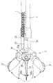
図1は、本発明の実施の形態の内視鏡用針付生検鉗子の先端部分を示している。シース1は、例えばステンレス鋼線材を一定の径で巻いた密着巻きコイルパイプによって形成されている。
【0014】
シース1の先端に連結固定された先端本体33には、長手方向にスリット34が形成されていて、その前端近傍に差し渡された状態に固設された支軸35に、一対の鉗子カップ31が嘴状に開閉するように回動自在に軸支されている。
【0015】
スリット34内には、鉗子カップ31を開閉作動させるために操作ワイヤ2によって駆動される公知のリンク機構36が配置されている。このリンク機構36は、四つのリンクを互いに回動自在に環状に連結したいわゆるパンタグラフ状に形成されており、そのうちの先側の二つのリンクは、一対の鉗子カップ31に一体に連続して形成されていて、支軸35を中心に回動する。
【0016】
リンク機構36の後端に連結された駆動ロッド37には、操作ワイヤ2の先端が連結固着されており、シース1の手元側からの遠隔操作によってリンク機構36を動作させ、操作ワイヤ2を先側へ押し込めば一対の鉗子カップ31が開き、操作ワイヤ2を手元側へ牽引すれば鉗子カップ31が二点鎖線で示されるように閉じる。
【0017】
先端本体33の先端部分から前方に向かって、一対の鉗子カップ31内に突出する針32が設けられている。針32は先端本体33及び一対の鉗子カップ31の中心軸線位置に配置されている。
【0018】
針32は、図2の部分平面断面図にも示されるように、基端部側に形成された孔に支軸35が通されて支持されており、側方に曲げて形成された腕部32aの端部が、先端本体33に形成された孔33aにかしめ固定されて回転止めになっている。
【0019】
図1に戻って、針32の先端は一対の鉗子カップ31が閉じた状態では鉗子カップ31内に納まる長さに設定されており、針32の先端近傍には、斜め後方に向かって突出する一対の刺状部32bが180°対称の位置に突設されている。
【0020】
上述のように構成された内視鏡用針付生検鉗子によって粘膜面から組織標本を採取する際には、鉗子カップ31を開いて針32を粘膜100に突き刺したら、従来とは逆に、そのまま内視鏡用針付生検鉗子を手元側に引き戻すように操作する。
【0021】
すると、図4に示されるように、針32から突設された刺状部32bによって粘膜100が引っ張り上げられ、このように粘膜100が引き伸ばされた状態で鉗子カップ31を閉じることにより、粘膜100の表面寄りの組織標本を適量採取することができ、鉗子カップ31を閉じる際の切れ味もよい。
【0022】
また、標本採取の位置も見当がつけ易くて安全であり、図5に示されるように、組織標本が切り取られた粘膜100の残り部分が適当な厚みを有し、出血が少なくて穿孔の心配もない。
【0023】
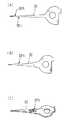
なお、本発明は上記実施の形態に限定されるものではなく、例えば刺状部32bは、図6の(A)に示されるように、位置をずらせて一対(又はそれ以上)配置されていてもよく、(B)に示されるように刺状部32bは少なくとも一個あればよく、(C)に示されるように、板材により形成された針32の一部を折り曲げて刺状部32bを形成してもよい。
【0024】
【発明の効果】
本発明によれば、斜め後方に向かって突出する刺状部を針の先端近傍に突設したので、粘膜面から組織標本を採取する際には、鉗子カップを開いて針を粘膜に突き刺し、そのまま生検鉗子を手元側に引き戻すように操作することにより、針から突設された刺状部によって粘膜が引っ張り上げられ、その状態で鉗子カップを閉じれば粘膜の表面寄りの組織標本を切れ味よく適量採取することができる。そして、標本採取の位置も見当がつけ易くて安全であり、組織標本が切り取られた粘膜の残り部分が適当な厚みを有し、出血が少なくて穿孔の心配もない。
【図面の簡単な説明】
【図1】本発明の実施の形態の内視鏡用針付生検鉗子の先端部分の側面断面図である。
【図2】本発明の実施の形態の内視鏡用針付生検鉗子の先端部分の部分平面断面図である。
【図3】本発明の実施の形態の内視鏡用針付生検鉗子の全体構成を示す側面図である。
【図4】本発明の実施の形態の内視鏡用針付生検鉗子の使用状態の先端部分の側面図である。
【図5】本発明の実施の形態の内視鏡用針付生検鉗子によって組織標本が採取された後の粘膜の状態を示す側面断面図である。
【図6】本発明の実施の形態の内視鏡用針付生検鉗子の針の複数の変形例を示す部品図である。
【図7】従来の内視鏡用針付生検鉗子の使用状態の先端部分の側面図である。
【図8】従来の内視鏡用針付生検鉗子によって組織標本が採取された後の粘膜の状態を示す側面断面図である。
【符号の説明】
1 シース
2 操作ワイヤ
31 鉗子カップ
32 針
32b 刺状部[0001]
BACKGROUND OF THE INVENTION
The present invention relates to an endoscopic needle-equipped biopsy forceps that is inserted into a forceps channel of an endoscope and used to collect a biopsy tissue specimen from within a body cavity.
[0002]
[Prior art]
An endoscopic biopsy forceps is generally a pair of forceps arranged at the distal end of a sheath by operating an operation wire inserted and removed in a sheath inserted into and removed from the forceps channel of the endoscope in the axial direction. The cup is driven to open and close like a bowl.
[0003]
And in the case of a biopsy forceps with a needle, when closing the forceps cup to collect a tissue specimen, the forceps cup slides on the mucosal surface and collects the specimen from the rear to the front. A needle that protrudes toward the center of the pair of forceps cups is provided.
[0004]
[Problems to be solved by the invention]
FIG. 7 shows a state in which a tissue specimen is collected from the mucosal surface using such a conventional endoscopic needle-equipped biopsy forceps. The
[0005]
When closing the
[0006]
Then, since the
[0007]
In addition, since the
[0008]
Therefore, an object of the present invention is to provide an endoscopic needle-equipped biopsy forceps capable of collecting a tissue sample of a mucous membrane from an appropriate depth at a correct position as intended.
[0009]
[Means for Solving the Problems]
In order to achieve the above object, a biopsy forceps with a needle for an endoscope according to the present invention is a pair of forceps that are opened and closed in a hook shape by operating an operation wire inserted and disposed in the sheath in an axial direction. In the biopsy forceps with a needle for an endoscope provided with a needle that protrudes into the pair of forceps cups from the rear to the front while the cup is disposed at the distal end of the sheath, a stab that protrudes obliquely rearward The portion is provided in the vicinity of the tip of the needle.
[0010]
Note that there may be at least one stab-like portion, and a pair of symmetrical portions may be arranged symmetrically, or a plurality of them may be arranged with their positions shifted.
[0011]
DETAILED DESCRIPTION OF THE INVENTION
Embodiments of the present invention will be described with reference to the drawings.
FIG. 3 shows the overall configuration of the endoscopic needle-equipped biopsy forceps according to the embodiment of the present invention. The flexible sheath 1 is inserted into and removed from an endoscopic forceps channel (not shown). An
[0012]
An operation unit 4 for moving the
[0013]
FIG. 1 shows a distal end portion of an endoscopic needle-equipped biopsy forceps according to an embodiment of the present invention. The sheath 1 is formed of, for example, a tightly wound coil pipe obtained by winding a stainless steel wire with a constant diameter.
[0014]
The
[0015]
A known
[0016]
The front end of the
[0017]
A
[0018]
As shown in the partial plan sectional view of FIG. 2, the
[0019]
Returning to FIG. 1, the tip of the
[0020]
When a tissue specimen is collected from the mucosal surface by the biopsy forceps with an endoscope needle configured as described above, if the
[0021]
Then, as shown in FIG. 4, the
[0022]
Further, the position of specimen collection is easy to find and safe, and as shown in FIG. 5, the remaining part of the
[0023]
In addition, this invention is not limited to the said embodiment, For example, as shown to (A) of FIG. 6, as for the stab-
[0024]
【The invention's effect】
According to the present invention, since the stab-like portion protruding obliquely rearward is provided in the vicinity of the tip of the needle, when collecting a tissue specimen from the mucosal surface, the forceps cup is opened and the needle is pierced into the mucous membrane. By operating the biopsy forceps as they are, the mucous membrane is pulled up by the stab-like portion protruding from the needle, and if the forceps cup is closed in this state, the tissue specimen closer to the surface of the mucosa is sharpened. Appropriate amount can be collected. The position of specimen collection is easy to find and safe, the remaining part of the mucous membrane from which the tissue specimen has been cut has an appropriate thickness, there is little bleeding, and there is no concern about perforation.
[Brief description of the drawings]
FIG. 1 is a side sectional view of a distal end portion of an endoscopic needle-equipped biopsy forceps according to an embodiment of the present invention.
FIG. 2 is a partial plan sectional view of a distal end portion of a biopsy forceps with a needle for an endoscope according to an embodiment of the present invention.
FIG. 3 is a side view showing the overall configuration of an endoscopic needle-equipped biopsy forceps according to an embodiment of the present invention.
FIG. 4 is a side view of the distal end portion of the biopsy forceps with a needle for endoscope according to the embodiment of the present invention in use.
FIG. 5 is a side cross-sectional view showing a state of a mucous membrane after a tissue specimen is collected by the biopsy forceps with an endoscope needle according to the embodiment of the present invention.
6 is a component diagram showing a plurality of modified examples of the needle of the biopsy forceps with an endoscope needle according to the embodiment of the present invention. FIG.
FIG. 7 is a side view of a distal end portion of a conventional endoscopic needle-equipped biopsy forceps in use.
FIG. 8 is a side sectional view showing a state of a mucous membrane after a tissue specimen is collected by a conventional endoscopic needle-equipped biopsy forceps.
[Explanation of symbols]
DESCRIPTION OF SYMBOLS 1
Claims (3)
Translated fromJapanese上記針の基端部側に形成された孔に上記支軸を通して上記針を上記支軸で支持すると共に、上記支軸より後方位置において上記針の基端を側方に曲げて、その端部を上記先端本体に形成された孔に固定し、
斜め後方に向かって突出する刺状部を上記針の先端近傍に突設したことを特徴とする内視鏡用針付生検鉗子。A slit that opens forward is formed in the distal end body provided at the distal end of the sheath, and a support shaft is attached to the distal end body so as to cross the slit, and an operation wire that is inserted and disposed in the sheath is provided. a pair of forceps cups driven to open and close the beakaround the said support shaft by reciprocating operation in the axial direction isprovided et the needle projecting into the pair of forcep cups are provided from the rear toward the front In biopsy forceps with a needle for endoscope,
The needle is supported by the support shaft through the support shaft in a hole formed on the proximal end side of the needle, and the proximal end of the needle is bent laterally at a position rearward of the support shaft. Is fixed to the hole formed in the tip body,
A biopsy forceps with a needle for an endoscope, wherein a stab-like portion protruding obliquely rearward is provided in the vicinity of the tip of the needle.
Priority Applications (1)
| Application Number | Priority Date | Filing Date | Title |
|---|---|---|---|
| JP20881799AJP4373536B2 (en) | 1999-07-23 | 1999-07-23 | Endoscopic biopsy forceps with needle |
Applications Claiming Priority (1)
| Application Number | Priority Date | Filing Date | Title |
|---|---|---|---|
| JP20881799AJP4373536B2 (en) | 1999-07-23 | 1999-07-23 | Endoscopic biopsy forceps with needle |
Publications (2)
| Publication Number | Publication Date |
|---|---|
| JP2001029349A JP2001029349A (en) | 2001-02-06 |
| JP4373536B2true JP4373536B2 (en) | 2009-11-25 |
Family
ID=16562624
Family Applications (1)
| Application Number | Title | Priority Date | Filing Date |
|---|---|---|---|
| JP20881799AExpired - Fee RelatedJP4373536B2 (en) | 1999-07-23 | 1999-07-23 | Endoscopic biopsy forceps with needle |
Country Status (1)
| Country | Link |
|---|---|
| JP (1) | JP4373536B2 (en) |
Families Citing this family (5)
| Publication number | Priority date | Publication date | Assignee | Title |
|---|---|---|---|---|
| US8469993B2 (en) | 2003-06-18 | 2013-06-25 | Boston Scientific Scimed, Inc. | Endoscopic instruments |
| US20040260337A1 (en) | 2003-06-18 | 2004-12-23 | Scimed Life Systems, Inc. | Endoscopic instruments and methods of manufacture |
| US7762960B2 (en) | 2005-05-13 | 2010-07-27 | Boston Scientific Scimed, Inc. | Biopsy forceps assemblies |
| JP4705201B2 (en) | 2009-03-05 | 2011-06-22 | オリンパスメディカルシステムズ株式会社 | Biopsy tissue collection device |
| CN107753092B (en)* | 2017-11-30 | 2024-01-19 | 彭翼 | Intra-cavity intima stripping device |
- 1999
- 1999-07-23JPJP20881799Apatent/JP4373536B2/ennot_activeExpired - Fee Related
Also Published As
| Publication number | Publication date |
|---|---|
| JP2001029349A (en) | 2001-02-06 |
Similar Documents
| Publication | Publication Date | Title |
|---|---|---|
| JP3634655B2 (en) | Endoscopic biopsy forceps | |
| JP4081557B2 (en) | Endoscopic multiple specimen biopsy forceps | |
| JP3615960B2 (en) | Endoscopic biopsy forceps with needle | |
| JP3691060B2 (en) | Multi-action specimen collection device for multiple biopsies | |
| EP1529492A3 (en) | Surgical biopsy device having automatic rotation of the probe for taking multiple samples | |
| JPH09501071A (en) | Multiple biopsy sampling device | |
| US6283924B1 (en) | Endoscopic biopsy forceps | |
| JP3718372B2 (en) | Endoscopic treatment tool | |
| JP4628637B2 (en) | Biopsy equipment | |
| JP4445617B2 (en) | Endoscopic treatment tool | |
| US20060084886A1 (en) | Endoscopic multiple biopsy forceps with swing member | |
| JP4373536B2 (en) | Endoscopic biopsy forceps with needle | |
| JPH10137251A (en) | Continuous biopsy tool | |
| EP1985239A1 (en) | Biopsy forceps | |
| JP3076658B2 (en) | Endoscope biopsy forceps | |
| JP2002119514A (en) | Endoscope biopsy forceps | |
| JP4618880B2 (en) | Endoscopic biopsy forceps for endoscope | |
| JPH03139340A (en) | Treating implement for endoscope | |
| JP4132343B2 (en) | Biopsy forceps | |
| JP2002282265A (en) | Endoscope forceps | |
| JP7087496B2 (en) | Tow clip for endoscope | |
| JPH0889475A (en) | Endoscopic treatment tool | |
| JP4338267B2 (en) | Endoscopic biopsy forceps | |
| JP4566358B2 (en) | Endoscopic biopsy forceps | |
| JP4459334B2 (en) | Endoscopic biopsy forceps |
Legal Events
| Date | Code | Title | Description |
|---|---|---|---|
| A621 | Written request for application examination | Free format text:JAPANESE INTERMEDIATE CODE: A621 Effective date:20060621 | |
| A711 | Notification of change in applicant | Free format text:JAPANESE INTERMEDIATE CODE: A712 Effective date:20080428 | |
| A131 | Notification of reasons for refusal | Free format text:JAPANESE INTERMEDIATE CODE: A131 Effective date:20090409 | |
| A521 | Written amendment | Free format text:JAPANESE INTERMEDIATE CODE: A523 Effective date:20090602 | |
| TRDD | Decision of grant or rejection written | ||
| A01 | Written decision to grant a patent or to grant a registration (utility model) | Free format text:JAPANESE INTERMEDIATE CODE: A01 Effective date:20090827 | |
| A01 | Written decision to grant a patent or to grant a registration (utility model) | Free format text:JAPANESE INTERMEDIATE CODE: A01 | |
| A61 | First payment of annual fees (during grant procedure) | Free format text:JAPANESE INTERMEDIATE CODE: A61 Effective date:20090904 | |
| FPAY | Renewal fee payment (event date is renewal date of database) | Free format text:PAYMENT UNTIL: 20120911 Year of fee payment:3 | |
| R150 | Certificate of patent or registration of utility model | Free format text:JAPANESE INTERMEDIATE CODE: R150 | |
| FPAY | Renewal fee payment (event date is renewal date of database) | Free format text:PAYMENT UNTIL: 20130911 Year of fee payment:4 | |
| R250 | Receipt of annual fees | Free format text:JAPANESE INTERMEDIATE CODE: R250 | |
| S533 | Written request for registration of change of name | Free format text:JAPANESE INTERMEDIATE CODE: R313533 | |
| S533 | Written request for registration of change of name | Free format text:JAPANESE INTERMEDIATE CODE: R313533 | |
| R350 | Written notification of registration of transfer | Free format text:JAPANESE INTERMEDIATE CODE: R350 | |
| R250 | Receipt of annual fees | Free format text:JAPANESE INTERMEDIATE CODE: R250 | |
| R250 | Receipt of annual fees | Free format text:JAPANESE INTERMEDIATE CODE: R250 | |
| S531 | Written request for registration of change of domicile | Free format text:JAPANESE INTERMEDIATE CODE: R313531 | |
| R350 | Written notification of registration of transfer | Free format text:JAPANESE INTERMEDIATE CODE: R350 | |
| R250 | Receipt of annual fees | Free format text:JAPANESE INTERMEDIATE CODE: R250 | |
| R250 | Receipt of annual fees | Free format text:JAPANESE INTERMEDIATE CODE: R250 | |
| LAPS | Cancellation because of no payment of annual fees |