JP4370198B2 - Intra-subject introduction device - Google Patents
Intra-subject introduction deviceDownload PDFInfo
- Publication number
- JP4370198B2 JP4370198B2JP2004139892AJP2004139892AJP4370198B2JP 4370198 B2JP4370198 B2JP 4370198B2JP 2004139892 AJP2004139892 AJP 2004139892AJP 2004139892 AJP2004139892 AJP 2004139892AJP 4370198 B2JP4370198 B2JP 4370198B2
- Authority
- JP
- Japan
- Prior art keywords
- clock
- subject
- wireless transmission
- unit
- imaging
- Prior art date
- Legal status (The legal status is an assumption and is not a legal conclusion. Google has not performed a legal analysis and makes no representation as to the accuracy of the status listed.)
- Expired - Fee Related
Links
- 230000005540biological transmissionEffects0.000claimsdescription58
- 238000003384imaging methodMethods0.000claimsdescription32
- 238000005286illuminationMethods0.000claimsdescription5
- 238000012937correctionMethods0.000claimsdescription3
- 239000002775capsuleSubstances0.000description24
- 238000012545processingMethods0.000description19
- 238000001727in vivoMethods0.000description9
- 238000010586diagramMethods0.000description8
- 230000006870functionEffects0.000description7
- 238000006243chemical reactionMethods0.000description6
- 238000012546transferMethods0.000description4
- 230000010355oscillationEffects0.000description3
- 230000001360synchronised effectEffects0.000description3
- 230000033001locomotionEffects0.000description2
- 210000000056organAnatomy0.000description2
- 230000035945sensitivityEffects0.000description2
- 238000004891communicationMethods0.000description1
- 238000003745diagnosisMethods0.000description1
- 239000000284extractSubstances0.000description1
- 230000001678irradiating effectEffects0.000description1
- 239000004973liquid crystal related substanceSubstances0.000description1
- 230000007246mechanismEffects0.000description1
- 230000006386memory functionEffects0.000description1
- 238000000034methodMethods0.000description1
- 238000012986modificationMethods0.000description1
- 230000004048modificationEffects0.000description1
- 230000002572peristaltic effectEffects0.000description1
- 230000000630rising effectEffects0.000description1
- 210000000813small intestineAnatomy0.000description1
- 230000000087stabilizing effectEffects0.000description1
- 210000002784stomachAnatomy0.000description1
- 230000009747swallowingEffects0.000description1
- 238000012360testing methodMethods0.000description1
Images


Classifications
- A—HUMAN NECESSITIES
- A61—MEDICAL OR VETERINARY SCIENCE; HYGIENE
- A61B—DIAGNOSIS; SURGERY; IDENTIFICATION
- A61B1/00—Instruments for performing medical examinations of the interior of cavities or tubes of the body by visual or photographical inspection, e.g. endoscopes; Illuminating arrangements therefor
- A61B1/04—Instruments for performing medical examinations of the interior of cavities or tubes of the body by visual or photographical inspection, e.g. endoscopes; Illuminating arrangements therefor combined with photographic or television appliances
- A61B1/041—Capsule endoscopes for imaging
- A—HUMAN NECESSITIES
- A61—MEDICAL OR VETERINARY SCIENCE; HYGIENE
- A61B—DIAGNOSIS; SURGERY; IDENTIFICATION
- A61B1/00—Instruments for performing medical examinations of the interior of cavities or tubes of the body by visual or photographical inspection, e.g. endoscopes; Illuminating arrangements therefor
- A61B1/00002—Operational features of endoscopes
- A61B1/00011—Operational features of endoscopes characterised by signal transmission
- A61B1/00016—Operational features of endoscopes characterised by signal transmission using wireless means
Landscapes
- Life Sciences & Earth Sciences (AREA)
- Health & Medical Sciences (AREA)
- Surgery (AREA)
- Engineering & Computer Science (AREA)
- Biophysics (AREA)
- Medical Informatics (AREA)
- Nuclear Medicine, Radiotherapy & Molecular Imaging (AREA)
- Optics & Photonics (AREA)
- Pathology (AREA)
- Radiology & Medical Imaging (AREA)
- Veterinary Medicine (AREA)
- Biomedical Technology (AREA)
- Heart & Thoracic Surgery (AREA)
- Physics & Mathematics (AREA)
- Molecular Biology (AREA)
- Animal Behavior & Ethology (AREA)
- General Health & Medical Sciences (AREA)
- Public Health (AREA)
- Computer Networks & Wireless Communication (AREA)
- Endoscopes (AREA)
- Measurement Of The Respiration, Hearing Ability, Form, And Blood Characteristics Of Living Organisms (AREA)
Description
Translated fromJapanese本発明は、被検体内部に導入された被検体内導入装置、たとえば飲み込み型のカプセル型内視鏡から画像情報を無線送信する際に、伝送搬送波を生成する被検体内導入装置に関するものである。 The present invention relates to an intra-subject introduction device introduced into a subject, for example, an intra-subject introduction device that generates a transmission carrier when wirelessly transmitting image information from a swallowable capsule endoscope. .
近年、内視鏡の分野では、撮像機能と無線機能とが装備されたカプセル型内視鏡が登場している。このカプセル型内視鏡は、観察(検査)のために被検体である被検者に飲み込まれた後、被検者の生体から自然排出されるまでの観察期間、胃、小腸などの臓器の内部(体腔内)をその蠕動運動に伴って移動し、撮像機能を用いて順次撮像する構成である。 In recent years, in the field of endoscopes, capsule endoscopes equipped with an imaging function and a wireless function have appeared. This capsule endoscope is used for observation (examination) after being swallowed by the subject, and during the observation period until it is naturally discharged from the subject's living body, organs such as the stomach and small intestine The inside (inside the body cavity) moves with the peristaltic motion and sequentially captures images using an imaging function.
また、これら臓器内の移動によるこの観察期間、カプセル型内視鏡によって体腔内で撮像された画像データは、順次無線通信などの無線機能により、被検体の外部に設けられた外部装置に送信され、外部装置内に設けられたメモリに蓄積される。被検者がこの無線機能とメモリ機能を備えた外部装置を携帯することにより、被検者は、カプセル型内視鏡を飲み込んだ後、排出されるまでの観察期間、不自由を被ることなく行動が可能になる。観察後は、医者もしくは看護士によって、外部装置のメモリに蓄積された画像データに基づいて、体腔内の画像をディスプレイなどの表示手段に表示させて診断を行うことができる。 Also, during this observation period due to movement in these organs, image data captured in the body cavity by the capsule endoscope is sequentially transmitted to an external device provided outside the subject by a wireless function such as wireless communication. Are stored in a memory provided in the external device. When the subject carries the external device having the wireless function and the memory function, the subject does not suffer any inconvenience during the observation period from swallowing the capsule endoscope until it is discharged. Action is possible. After observation, a doctor or nurse can make a diagnosis by displaying an image in the body cavity on a display means such as a display based on the image data stored in the memory of the external device.
この種のカプセル型内視鏡では、たとえば特許文献1に示すような飲み込み型のものがあり、カプセル型内視鏡に電力供給用の電池を内蔵し、この電池から供給される電力によってLEDが照明光の照射を行い、この照明光による被検体内からの反射像を撮像素子で撮像して画像情報を取得し、この画像情報を送信回路から無線送信する構成が提案されている。 In this type of capsule endoscope, for example, there is a swallow type as shown in
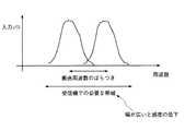
しかしながら、上記のカプセル型内視鏡では、一般に送信回路は、回路内に基準となるクロックを発生させるRF基準クロック発生回路を設け、この基準クロックを用いて伝送搬送波の伝送周波数を規定しており、現状のものでは、たとえば図6に示すように、伝送周波数にばらつきがあった場合には、受信機側でのバンドパスフィルタの通過帯域を広くする必要がある。このように通過帯域を広くすると、通過帯域の広さに対応してノイズなども含まれることとなり、受信感度の低下を招くという問題があった。 However, in the above capsule endoscope, generally, the transmission circuit is provided with an RF reference clock generation circuit for generating a reference clock in the circuit, and the transmission frequency of the transmission carrier is defined using this reference clock. In the present situation, for example, as shown in FIG. 6, when the transmission frequency varies, it is necessary to widen the pass band of the band pass filter on the receiver side. When the pass band is widened in this way, noise and the like are included corresponding to the width of the pass band, and there is a problem that the reception sensitivity is lowered.
本発明は、上記問題に鑑みてなされたものであって、安定した基準クロックの発振を行って伝送搬送波の伝送周波数のばらつきを抑えることができるとともに消費電力を削減することができる被検体内導入装置を提供することを目的とする。The present invention has been made in view of the above problems, andcan be introducedinto a subject to perform stable reference clock oscillation to suppress variation in transmission frequency of a transmission carrier andto reduce power consumption. An object is to provide an apparatus.
上述した課題を解決し、目的を達成するために、本発明にかかる被検体内導入装置は、被検体内部に導入されて、前記被検体内部の情報を取得する被検体内導入装置において、前記被検体内部を照明する照明光を出力する照明手段と、前記照明手段で照明された前記被検体内部の画像情報を取得する撮像手段と、前記被検体内部の情報を無線送信する無線送信手段と、前記撮像手段による画像情報取得のためのクロックを生成するクロック生成手段と、前記クロック生成手段で生成されたクロックに基づいて、前記無線送信手段による無線送信のためのクロックを補正する補正手段と、を備えることを特徴とする。 In order to solve the above-described problems and achieve the object, an in-subject introduction apparatus according to the present invention is introduced into a subject and acquires information inside the subject. Illuminating means for outputting illumination light for illuminating the inside of the subject, imaging means for acquiring image information inside the subject illuminated by the illuminating means, and wireless transmitting means for wirelessly transmitting information inside the subject. A clock generating means for generating a clock for acquiring image information by the imaging means; a correcting means for correcting a clock for wireless transmission by the wireless transmitting means based on the clock generated by the clock generating means; It is characterized by providing.
また、請求項2の発明にかかる被検体内導入装置は、上記発明において、前記クロック生成手段は、前記生成したクロックを分周する分周手段を含み、前記分周手段で分周したクロックを前記無線送信手段に出力することを特徴とする。 According to a second aspect of the present invention, in the in-vivo introduction device according to the second aspect of the invention, the clock generation means includes frequency dividing means for dividing the generated clock, and the clock divided by the frequency dividing means is used. It outputs to the said wireless transmission means, It is characterized by the above-mentioned.
また、請求項3の発明にかかる被検体内導入装置は、上記発明において、前記クロック生成手段は、前記撮像手段の駆動タイミング中は、前記無線送信手段への前記クロックの出力を停止することを特徴とする。 According to a third aspect of the present invention, there is provided the in-subject introduction device according to the above invention, wherein the clock generation unit stops outputting the clock to the wireless transmission unit during the drive timing of the imaging unit. Features.
また、請求項4の発明にかかる被検体内導入装置は、上記発明において、前記補正手段は、前記クロック生成手段からのクロックに前記無線送信手段による無線送信のためのクロックを同期させる同期手段を含むことを特徴とする。 According to a fourth aspect of the present invention, in the in-subject introduction apparatus according to the present invention, the correction means includes synchronization means for synchronizing a clock for wireless transmission by the wireless transmission means with a clock from the clock generation means. It is characterized by including.
また、請求項5の発明にかかる被検体内導入装置は、上記発明において、前記同期手段は、前記クロック生成手段からのクロックに前記無線送信手段による無線送信のためのクロックを位相同期させることを特徴とする。 In the in-vivo introduction device according to the invention of
また、請求項6の発明にかかる被検体内導入装置は、上記発明において、前記クロック生成手段は、前記無線送信手段が動作していない時は、前記無線送信手段への前記クロックの出力を停止することを特徴とする。 According to a sixth aspect of the present invention, in the in-vivo introduction device according to the present invention, the clock generation means stops outputting the clock to the wireless transmission means when the wireless transmission means is not operating. It is characterized by doing.
本発明にかかる被検体内導入装置は、撮像手段による画像情報取得のためのクロック、たとえば撮像系の撮像のタイミングをとるための精度の高い基準クロックから分周したクロックに基づいて、無線送信手段による無線送信のための基準クロックを補正することで、安定した基準クロックの発振を行って伝送搬送波の伝送周波数のばらつきを抑えることができるという効果を奏する。 The in-subject introduction apparatus according to the present invention is based on a clock for acquiring image information by an imaging unit, for example, a radio transmission unit based on a clock divided from a highly accurate reference clock for taking an imaging timing of an imaging system. By correcting the reference clock for wireless transmission according to the method, stable reference clock oscillation can be performed and variations in the transmission frequency of the transmission carrier can be suppressed.
以下に、本発明にかかる被検体内導入装置の実施の形態を図1〜図5の図面に基づいて詳細に説明する。なお、本発明は、これらの実施の形態に限定されるものではなく、本発明の要旨を逸脱しない範囲で種々の変更実施の形態が可能である。 Embodiments of an intra-subject introduction apparatus according to the present invention will be described below in detail based on the drawings of FIGS. The present invention is not limited to these embodiments, and various modifications can be made without departing from the scope of the present invention.
(実施の形態1)
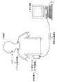
図1は、実施の形態1にかかる被検体内導入装置を含む無線型被検体内情報取得システムの全体構成を示す模式図である。この無線型被検体内情報取得システムでは、被検体内導入装置の一例として、カプセル型内視鏡をあげて説明する。図1において、無線型被検体内情報取得システムは、無線受信機能を有する受信装置3と、被検体1内に導入され、体腔内画像を撮像して受信装置3に対して映像信号などのデータ送信を行うカプセル型内視鏡(被検体内導入装置)2とを備える。また、無線型被検体内情報取得システムは、受信装置3が受信した映像信号に基づいて体腔内画像を表示する表示装置4と、受信装置3と表示装置4との間でデータの受け渡しを行うための携帯型記録媒体5とを備える。受信装置3は、被検体1によって着用される受信ジャケット31と、受信される無線信号の処理などを行う外部装置32とを備える。(Embodiment 1)
FIG. 1 is a schematic diagram illustrating an overall configuration of a wireless in-vivo information acquiring system including an in-subject introduction device according to the first embodiment. In this wireless in-vivo information acquiring system, a capsule endoscope will be described as an example of the in-subject introduction apparatus. In FIG. 1, a wireless in-vivo information acquisition system includes a
表示装置4は、カプセル型内視鏡2によって撮像された体腔内画像などを表示するためのものであり、携帯型記録媒体5によって得られるデータに基づいて画像表示を行うワークステーションなどのような構成を有する。具体的には、表示装置4は、CRTディスプレイ、液晶ディスプレイなどによって直接画像を表示する構成としても良いし、プリンタなどのように、他の媒体に画像を出力する構成としても良い。 The display device 4 is for displaying an in-vivo image captured by the
携帯型記録媒体5は、外部装置32および表示装置4に対して着脱可能であって、両者に対して挿着された時に情報の出力または記録が可能な構造を有する。この実施の形態では、携帯型記録媒体5は、カプセル型内視鏡2が被検体1の体腔内を移動している間は、外部装置32に挿着されてカプセル型内視鏡2から送信されるデータを記録する。そして、カプセル型内視鏡2が被検体1から排出された後、つまり、被検体1の内部の撮像が終了した後には、外部装置32から取り出されて表示装置4に挿着され、この表示装置4によって、携帯型記録媒体5に記録されたデータが読み出される構成を有する。たとえば、外部装置32と表示装置4とのデータの受け渡しを、コンパクトフラッシュ(登録商標)メモリなどから構成される携帯型記録媒体5によって行うことで、外部装置32と表示装置4との間が有線で直接接続された場合よりも、被検体1が体腔内の撮影中に自由に動作することが可能となる。なお、ここでは、外部装置32と表示装置4との間のデータの受け渡しに携帯型記録媒体5を使用したが、必ずしもこれに限らず、たとえば外部装置32に内蔵型の他の記録装置、たとえばハードディスクを用い、表示装置4との間のデータの受け渡しのために、双方を有線または無線接続するように構成してもよい。 The
次に、図2のブロック図を用いて受信装置の構成について説明する。受信装置3は、カプセル型内視鏡2から無線送信された体腔内の画像データを受信する機能を有する。図2に示すように、受信装置3は、被検体1によって着用可能な形状を有し、受信用アンテナA1〜Anを備えた受信ジャケット31と、受信ジャケット31を介して受信された無線信号の処理などを行う外部装置32とを備える。なお、各受信用アンテナA1〜Anは、直接被検体1の外表面に貼付して、受信ジャケット31に備え付けられなくてもよく、また受信ジャケット31に着脱可能なものでもよい。 Next, the configuration of the receiving apparatus will be described with reference to the block diagram of FIG. The
外部装置32は、受信用アンテナA1〜Anによって受信された無線信号に対して復調などの所定の信号処理を行い、無線信号の中からカプセル型内視鏡2によって取得された画像データを抽出するRF受信ユニット33と、抽出された画像データに必要な画像処理を行う画像処理ユニット34と、画像処理が施された画像データを記録するための記憶ユニット35とを備え、カプセル型内視鏡2から送信された無線信号の信号処理を行う。なお、この実施の形態では、記憶ユニット35を介して携帯型記録媒体5に画像データが記録されている。さらに、外部装置32は、所定の蓄電装置またはAC電源アダプタなどを備えた電力供給ユニット38を備え、外部装置32の各構成要素は、電力供給ユニット38から供給される電力を駆動エネルギーとしている。 The
次に、図3のブロック図を用いてカプセル型内視鏡の構成を説明する。カプセル型内視鏡2は、図3のブロック図に示すように、たとえば被検体1の体腔内における被検部位を照射するための照明手段としての発光素子(LED)20と、LED20の駆動状態を制御するLED駆動回路21と、LED20によって照射された領域からの反射光である体腔内の画像を撮像する撮像手段としての電荷結合素子(CCD)23と、CCD23の駆動状態を制御するとしてのCCD駆動回路24と、CCD23から出力された画像信号を所望の形式の画像情報に処理する信号処理回路25と、LED20の点灯タイミングやCCD23の撮像タイミングなどの駆動タイミングを与えるための基準クロックを出力するクロック生成手段としての撮像タイミング発生回路26とを備える。また、カプセル型内視鏡2は、この撮像された画像信号をRF信号に変調するRF送信ユニット27と、RF送信ユニット27から出力されたRF信号を無線送信する無線送信手段としての送信アンテナ部28とを備える。さらに、カプセル型内視鏡2は、これらLED駆動回路21、CCD駆動回路24およびRF送信ユニット27の動作を制御するシステムコントロール回路29を備える。なお、CCD23、CCD駆動回路24、信号処理回路25、および撮像タイミング発生回路26をまとめて撮像部22と呼ぶ。これらの機構を備えることにより、このカプセル型内視鏡2は、被検体1内に導入されている間、LED20によって照射された被検部位の画像情報を、所望の撮像タイミングを構成する基準クロックに基づき、CCD23によって取得するように動作している。この取得された画像情報は、この基準クロックに基づき、信号処理回路25によって信号処理され、さらにRF送信ユニット27によってRF信号に変換された後、送信アンテナ部28を介して被検体1の外部に送信されている。 Next, the configuration of the capsule endoscope will be described with reference to the block diagram of FIG. As shown in the block diagram of FIG. 3, the
すなわち、撮像タイミング発生回路26は、図示しない基準クロックを発生する回路を内蔵し、図4に示すように、LED駆動回路21、CCD駆動回路24および信号処理回路25に駆動タイミングを構成する基準クロックを出力するとともに、この基準クロックを分周する分周手段としてのRF用クロック分周回路26aを備え、このRF用クロック分周回路26aから分周したクロックをRF送信ユニット27に出力している。この撮像タイミング発生回路26から出力される基準クロックは、撮像素子の駆動信号における微小なタイミングの基準になるように高精度に構成されており、周波数のずれの絶対値が小さく設定されている。そこで、この実施の形態では、RF用クロックを出力するにあたり、CCDの撮像タイミングを構成する高精度の基準クロックを、RF用クロック分周回路26aで分周することで、RFの基準クロックを位相同期させるためのRF用クロックを生成して、RF送信ユニット27に出力することによって伝送搬送波の安定発振を可能にする。これにより高精度なクロックをRF送信ユニット内に別に搭載する必要がなくなる。 That is, the imaging
また、CCD23から出力された画像信号は、信号処理回路25の信号処理部25aで所望の信号処理が施され、A/D変換部25bのA/D変換によってデジタル信号に変換され、さらにP/S変換部25cでパラレル/シリアル変換によってシリアル信号に変換され、エンコード部25dで符号化された後に、RF送信ユニット27に出力されている。 The image signal output from the
RF送信ユニット27は、RF用クロック分周回路26aで分周されたクロックを取り込む同期手段としてのPLL回路27aを備える。すなわち、RF用クロック分周回路26aからは、たとえば図5に示すように、撮像用基準クロックを4分周したRF用クロックを出力しており、PLL回路27aは、このRF用クロックに基づいて、フェーズロックをかけ、RF用クロックの立ち上がり(または立ち下がり)で、RF基準クロックの位相を同期させることによって、伝送搬送波を安定的に発振させて伝送周波数のバラツキを抑えた後に、画像情報の無線送信を行う。 The
このように、この実施の形態では、撮像部から周波数の安定精度の高いRF用クロックをRF送信ユニットに出力して、RF基準クロックの位相をこのRF用クロックに同期させることで、安定したRF基準クロックの発振を行って伝送搬送波の伝送周波数のばらつきを抑えることができ、これによって受信装置側でのバンドパスフィルタの通過帯域を狭帯域に設定することが可能となり、ノイズの少ない感度の良い画像情報を受信することができる。 As described above, in this embodiment, an RF clock with high frequency stability accuracy is output from the imaging unit to the RF transmission unit, and the phase of the RF reference clock is synchronized with the RF clock, thereby stabilizing the RF. By oscillating the reference clock, it is possible to suppress variations in the transmission frequency of the transmission carrier wave, which makes it possible to set the passband of the bandpass filter on the receiving device side to a narrow band, and the sensitivity is low and noise is good. Image information can be received.
また、この実施の形態では、CCDの撮像タイミングを構成する撮像用基準クロックから分周したクロックをRF送信ユニットに出力し、RF基準クロックを補正するので、撮像部22を構成するICの出力ピンの出力電流を少なくすることができ、クロック出力ICの消費電流を低減することもできる。 In this embodiment, since the clock divided from the imaging reference clock constituting the imaging timing of the CCD is output to the RF transmission unit and the RF reference clock is corrected, the output pin of the IC constituting the
なお、この実施の形態では、たとえばCCDの駆動タイミング中は、分周回路から出力するRF用クロックを停止させ、イネーブル信号を用いてCCDの駆動状態をRF送信ユニット27に報知することも可能である。この撮像タイミング発生回路26の動作によって、RF送信ユニットは駆動を停止させることが可能となり、システム全体の消費電力の削減を図ることができる。合わせて画像信号が入力されずRF送信ユニット27を駆動する必要がない期間に、RF用クロックを停止させることによって、さらに消費電力を削減することが可能となる。また、RF用クロック分周回路は、たとえばRF用クロックとRF基準クロックの同期が可能なように、RF用クロックをCCDの1画素の転送周波数より高く設定することも可能であり、たとえばこの分周によって高周波数帯域のRF基準クロックを直接生成して、このRF基準クロックをRF送信ユニットに出力することも可能である。 In this embodiment, for example, during the drive timing of the CCD, it is possible to stop the RF clock output from the frequency dividing circuit and inform the
1 被検体
2 カプセル型内視鏡
3 受信装置
4 表示装置
5 携帯型記録媒体
20 LED
21 LED駆動回路
22 撮像部
23 CCD
24 CCD駆動回路
25 信号処理回路
25a 信号処理部
25b A/D変換部
25c P/S変換部
25d エンコード部
26 撮像タイミング発生回路
26a RF用クロック分周回路
27 RF送信アンテナ部
27a PLL回路
28 送信アンテナ部
29 システムコントロール回路
31 受信ジャケット
32 外部装置
33 RF受信ユニット
34 画像処理ユニット
35 記憶ユニット
38 電力供給ユニット
A1〜An 受信用アンテナDESCRIPTION OF
21
24
Claims (4)
Translated fromJapanese前記被検体内部を照明する照明光を出力する照明手段と、
前記照明手段で照明された前記被検体内部の画像情報を取得する撮像手段と、
前記被検体内部の情報を無線送信する無線送信手段と、
前記撮像手段による画像情報取得のためのクロックを生成するクロック生成手段と、
前記クロック生成手段で生成されたクロックに基づいて、前記無線送信手段による無線送信のためのクロックを補正する補正手段と、
を備え、
前記クロック生成手段は、前記生成したクロックを分周する分周手段を含み、前記分周手段で分周したクロックを前記無線送信手段に出力するとともに、前記無線送信手段が動作していない時は、前記無線送信手段への前記クロックの出力を停止することを特徴とする被検体内導入装置。In the in-subject introduction apparatus that is introduced into the subject and acquires information inside the subject,
Illuminating means for outputting illumination light for illuminating the inside of the subject;
Imaging means for acquiring image information inside the subject illuminated by the illumination means;
Wireless transmission means for wirelessly transmitting information inside the subject;
Clock generation means for generating a clock for acquiring image information by the imaging means;
Correction means for correcting a clock for wireless transmission by the wireless transmission means based on the clock generated by the clock generation means;
Bei togive a,
The clock generation means includes frequency dividing means for dividing the generated clock, and outputs the clock divided by the frequency dividing means to the wireless transmission means, and when the wireless transmission means is not operating. An in-subject introduction apparatus, wherein output of the clock to the wireless transmission means is stopped .
Priority Applications (5)
| Application Number | Priority Date | Filing Date | Title |
|---|---|---|---|
| JP2004139892AJP4370198B2 (en) | 2004-05-10 | 2004-05-10 | Intra-subject introduction device |
| PCT/JP2005/007407WO2005107572A1 (en) | 2004-05-10 | 2005-04-18 | Device for introduction into subject |
| EP05730678AEP1747748B1 (en) | 2004-05-10 | 2005-04-18 | Device for introduction into subject |
| CNB2005800149299ACN100450424C (en) | 2004-05-10 | 2005-04-18 | Device for introduction into subject |
| US11/595,052US7860471B2 (en) | 2004-05-10 | 2006-11-09 | Body-insertable apparatus |
Applications Claiming Priority (1)
| Application Number | Priority Date | Filing Date | Title |
|---|---|---|---|
| JP2004139892AJP4370198B2 (en) | 2004-05-10 | 2004-05-10 | Intra-subject introduction device |
Publications (3)
| Publication Number | Publication Date |
|---|---|
| JP2005319098A JP2005319098A (en) | 2005-11-17 |
| JP2005319098A5 JP2005319098A5 (en) | 2007-06-28 |
| JP4370198B2true JP4370198B2 (en) | 2009-11-25 |
Family
ID=35319991
Family Applications (1)
| Application Number | Title | Priority Date | Filing Date |
|---|---|---|---|
| JP2004139892AExpired - Fee RelatedJP4370198B2 (en) | 2004-05-10 | 2004-05-10 | Intra-subject introduction device |
Country Status (5)
| Country | Link |
|---|---|
| US (1) | US7860471B2 (en) |
| EP (1) | EP1747748B1 (en) |
| JP (1) | JP4370198B2 (en) |
| CN (1) | CN100450424C (en) |
| WO (1) | WO2005107572A1 (en) |
Families Citing this family (5)
| Publication number | Priority date | Publication date | Assignee | Title |
|---|---|---|---|---|
| JP2007260066A (en)* | 2006-03-28 | 2007-10-11 | Pentax Corp | Endoscope device |
| JP2008036356A (en)* | 2006-08-10 | 2008-02-21 | Olympus Corp | Electronic endoscope unit and electronic endoscope system |
| JP5622350B2 (en)* | 2007-12-05 | 2014-11-12 | オリンパスメディカルシステムズ株式会社 | Intra-subject introduction apparatus and intra-subject information acquisition system |
| WO2020144862A1 (en)* | 2019-01-11 | 2020-07-16 | オリンパス株式会社 | Capsule endoscope system and reception device |
| US11627243B2 (en)* | 2021-07-23 | 2023-04-11 | Phaox LLC | Handheld wireless endoscope image streaming apparatus |
Family Cites Families (12)
| Publication number | Priority date | Publication date | Assignee | Title |
|---|---|---|---|---|
| KR920003656B1 (en)* | 1988-04-01 | 1992-05-06 | 샤프 가부시끼 가이샤 | Image pickup device with electronic telescope |
| US5408265A (en)* | 1992-02-07 | 1995-04-18 | Olympus Optical Co., Ltd. | Electronic endoscope system adaptable to different T.V. standards while utilizing a common light source |
| IL108352A (en) | 1994-01-17 | 2000-02-29 | Given Imaging Ltd | In vivo video camera system |
| US6081733A (en)* | 1997-04-16 | 2000-06-27 | Motorola, Inc. | Communication control apparatus and method |
| AU1419001A (en)* | 1999-11-22 | 2001-06-04 | Macros Japan Inc. | Call suppressor for spread spectrum portable telephone |
| JP2001245844A (en)* | 2000-03-03 | 2001-09-11 | Asahi Optical Co Ltd | Capsule endoscope |
| DE20122488U1 (en)* | 2000-03-08 | 2005-12-15 | Given Imaging Ltd. | In vivo imaging system for use in applications such as imaging digestive tract, uses camera, illumination source and transmitter enclosed in capsule suitable for insertion into and passing through body lumens or cavities |
| JP4382249B2 (en)* | 2000-04-27 | 2009-12-09 | マスプロ電工株式会社 | In-vehicle satellite tracking device and in-vehicle satellite receiving system |
| JP2002345743A (en) | 2001-05-28 | 2002-12-03 | Fuji Photo Film Co Ltd | Capsule endoscope |
| JP4152606B2 (en) | 2001-06-26 | 2008-09-17 | 三菱電機株式会社 | Mobile terminal device with built-in imaging function |
| JP4744026B2 (en)* | 2001-07-30 | 2011-08-10 | オリンパス株式会社 | Capsule endoscope and capsule endoscope system |
| JP4363843B2 (en)* | 2002-03-08 | 2009-11-11 | オリンパス株式会社 | Capsule endoscope |
- 2004
- 2004-05-10JPJP2004139892Apatent/JP4370198B2/ennot_activeExpired - Fee Related
- 2005
- 2005-04-18EPEP05730678Apatent/EP1747748B1/ennot_activeExpired - Lifetime
- 2005-04-18WOPCT/JP2005/007407patent/WO2005107572A1/enactiveApplication Filing
- 2005-04-18CNCNB2005800149299Apatent/CN100450424C/ennot_activeExpired - Fee Related
- 2006
- 2006-11-09USUS11/595,052patent/US7860471B2/enactiveActive
Also Published As
| Publication number | Publication date |
|---|---|
| EP1747748A4 (en) | 2010-03-03 |
| US7860471B2 (en) | 2010-12-28 |
| CN1950020A (en) | 2007-04-18 |
| WO2005107572A1 (en) | 2005-11-17 |
| EP1747748A1 (en) | 2007-01-31 |
| CN100450424C (en) | 2009-01-14 |
| EP1747748B1 (en) | 2012-01-25 |
| JP2005319098A (en) | 2005-11-17 |
| US20070083083A1 (en) | 2007-04-12 |
Similar Documents
| Publication | Publication Date | Title |
|---|---|---|
| EP1779777B1 (en) | A device for in vivo imaging | |
| US7881668B2 (en) | Receiving apparatus for swallow-type capsule endoscope | |
| CN101868174B (en) | Introduced device in the subject and information acquisition system in the subject | |
| JP4948049B2 (en) | Capsule endoscope system | |
| JP4542370B2 (en) | Intra-subject introduction device | |
| JP4445799B2 (en) | Intra-subject introduction device and medical device | |
| US7860471B2 (en) | Body-insertable apparatus | |
| JP4526315B2 (en) | Intra-subject introduction apparatus and intra-subject information acquisition system | |
| JP4384544B2 (en) | Receiver | |
| JP4150711B2 (en) | Imaging device | |
| JP4847075B2 (en) | Receiver | |
| JP2007089892A (en) | Apparatus introduced into subject, apparatus used outside of subject, and system introduced into subject | |
| JP2005334080A (en) | Apparatus introduced into subject and medical instrument | |
| JP4445733B2 (en) | In-subject introduction apparatus and wireless in-subject information acquisition system | |
| JP4398193B2 (en) | Wireless in-vivo information acquisition system | |
| JP4804831B2 (en) | In-subject information acquisition system | |
| JP4656825B2 (en) | In-subject introduction apparatus and wireless in-subject information acquisition system | |
| JP2006075365A (en) | Receiver apparatus and subject internal guiding system | |
| JP2006020702A (en) | Device and system for introduction into subject | |
| CN101267763A (en) | receiving device | |
| JP4025766B2 (en) | Receiver and transmitter | |
| JP2005287685A (en) | Extra-patient apparatus, and intra-patient introduction apparatus and system | |
| WO2019111470A1 (en) | Communication module, capsule endoscope and reception unit | |
| JP4892065B2 (en) | Receiver and in-subject information acquisition system | |
| JP2008252933A (en) | Imaging apparatus |
Legal Events
| Date | Code | Title | Description |
|---|---|---|---|
| A521 | Request for written amendment filed | Free format text:JAPANESE INTERMEDIATE CODE: A523 Effective date:20070510 | |
| A621 | Written request for application examination | Free format text:JAPANESE INTERMEDIATE CODE: A621 Effective date:20070510 | |
| TRDD | Decision of grant or rejection written | ||
| A01 | Written decision to grant a patent or to grant a registration (utility model) | Free format text:JAPANESE INTERMEDIATE CODE: A01 Effective date:20090804 | |
| A01 | Written decision to grant a patent or to grant a registration (utility model) | Free format text:JAPANESE INTERMEDIATE CODE: A01 | |
| A61 | First payment of annual fees (during grant procedure) | Free format text:JAPANESE INTERMEDIATE CODE: A61 Effective date:20090831 | |
| R151 | Written notification of patent or utility model registration | Ref document number:4370198 Country of ref document:JP Free format text:JAPANESE INTERMEDIATE CODE: R151 | |
| FPAY | Renewal fee payment (event date is renewal date of database) | Free format text:PAYMENT UNTIL: 20120904 Year of fee payment:3 | |
| FPAY | Renewal fee payment (event date is renewal date of database) | Free format text:PAYMENT UNTIL: 20130904 Year of fee payment:4 | |
| S531 | Written request for registration of change of domicile | Free format text:JAPANESE INTERMEDIATE CODE: R313531 | |
| R350 | Written notification of registration of transfer | Free format text:JAPANESE INTERMEDIATE CODE: R350 | |
| R250 | Receipt of annual fees | Free format text:JAPANESE INTERMEDIATE CODE: R250 | |
| R250 | Receipt of annual fees | Free format text:JAPANESE INTERMEDIATE CODE: R250 | |
| R250 | Receipt of annual fees | Free format text:JAPANESE INTERMEDIATE CODE: R250 | |
| R250 | Receipt of annual fees | Free format text:JAPANESE INTERMEDIATE CODE: R250 | |
| LAPS | Cancellation because of no payment of annual fees |