JP4366306B2 - In vivo tissue closure device and in vivo tissue closure device - Google Patents
In vivo tissue closure device and in vivo tissue closure deviceDownload PDFInfo
- Publication number
- JP4366306B2 JP4366306B2JP2004366780AJP2004366780AJP4366306B2JP 4366306 B2JP4366306 B2JP 4366306B2JP 2004366780 AJP2004366780 AJP 2004366780AJP 2004366780 AJP2004366780 AJP 2004366780AJP 4366306 B2JP4366306 B2JP 4366306B2
- Authority
- JP
- Japan
- Prior art keywords
- vivo tissue
- tissue closure
- closure device
- thread
- deformable
- Prior art date
- Legal status (The legal status is an assumption and is not a legal conclusion. Google has not performed a legal analysis and makes no representation as to the accuracy of the status listed.)
- Expired - Fee Related
Links
- 238000001727in vivoMethods0.000titleclaimsdescription188
- 210000004204blood vesselAnatomy0.000claimsdescription43
- 239000000463materialSubstances0.000claimsdescription18
- 210000000078clawAnatomy0.000claimsdescription13
- 230000002093peripheral effectEffects0.000claimsdescription12
- 230000000149penetrating effectEffects0.000claimsdescription11
- 230000009466transformationEffects0.000claimsdescription8
- 238000007789sealingMethods0.000claimsdescription7
- 238000000034methodMethods0.000claimsdescription6
- 238000005452bendingMethods0.000claimsdescription5
- 238000013459approachMethods0.000claimsdescription3
- 210000001519tissueAnatomy0.000description143
- 230000023597hemostasisEffects0.000description18
- 230000000694effectsEffects0.000description14
- 230000002439hemostatic effectEffects0.000description6
- 210000004369bloodAnatomy0.000description3
- 239000008280bloodSubstances0.000description3
- 230000006835compressionEffects0.000description3
- 238000007906compressionMethods0.000description3
- 238000010586diagramMethods0.000description3
- 210000001105femoral arteryAnatomy0.000description3
- 229920005989resinPolymers0.000description3
- 239000011347resinSubstances0.000description3
- 230000000740bleeding effectEffects0.000description2
- 230000036772blood pressureEffects0.000description2
- 238000012790confirmationMethods0.000description2
- 239000000470constituentSubstances0.000description2
- 238000003745diagnosisMethods0.000description2
- 238000003780insertionMethods0.000description2
- 230000037431insertionEffects0.000description2
- 206010033675panniculitisDiseases0.000description2
- 210000004304subcutaneous tissueAnatomy0.000description2
- 230000001225therapeutic effectEffects0.000description2
- DHOZGVQOZATZGP-UHFFFAOYSA-NCC(CCN)C=CChemical compoundCC(CCN)C=CDHOZGVQOZATZGP-UHFFFAOYSA-N0.000description1
- 208000031481Pathologic ConstrictionDiseases0.000description1
- 229920000954PolyglycolidePolymers0.000description1
- 239000000560biocompatible materialSubstances0.000description1
- 210000001124body fluidAnatomy0.000description1
- 239000010839body fluidSubstances0.000description1
- 239000002131composite materialSubstances0.000description1
- 210000004351coronary vesselAnatomy0.000description1
- 230000003176fibrotic effectEffects0.000description1
- 239000004615ingredientSubstances0.000description1
- 230000003902lesionEffects0.000description1
- 239000002184metalSubstances0.000description1
- 238000002324minimally invasive surgeryMethods0.000description1
- 230000000704physical effectEffects0.000description1
- 229920000747poly(lactic acid)Polymers0.000description1
- 229920002463poly(p-dioxanone) polymerPolymers0.000description1
- 239000000622polydioxanoneSubstances0.000description1
- 239000004633polyglycolic acidSubstances0.000description1
- 239000004626polylactic acidSubstances0.000description1
- 239000011148porous materialSubstances0.000description1
- 208000037804stenosisDiseases0.000description1
- 230000036262stenosisEffects0.000description1
- 239000000126substanceSubstances0.000description1
- 229920003002synthetic resinPolymers0.000description1
- 239000000057synthetic resinSubstances0.000description1
- 238000012546transferMethods0.000description1
- 210000000689upper legAnatomy0.000description1
- 208000019553vascular diseaseDiseases0.000description1
- 231100000216vascular lesionToxicity0.000description1
- 210000001835visceraAnatomy0.000description1
Images


Classifications
- A—HUMAN NECESSITIES
- A61—MEDICAL OR VETERINARY SCIENCE; HYGIENE
- A61B—DIAGNOSIS; SURGERY; IDENTIFICATION
- A61B17/00—Surgical instruments, devices or methods
- A61B17/0057—Implements for plugging an opening in the wall of a hollow or tubular organ, e.g. for sealing a vessel puncture or closing a cardiac septal defect
- A61B2017/00575—Implements for plugging an opening in the wall of a hollow or tubular organ, e.g. for sealing a vessel puncture or closing a cardiac septal defect for closure at remote site, e.g. closing atrial septum defects
- A61B2017/00606—Implements H-shaped in cross-section, i.e. with occluders on both sides of the opening
- A—HUMAN NECESSITIES
- A61—MEDICAL OR VETERINARY SCIENCE; HYGIENE
- A61B—DIAGNOSIS; SURGERY; IDENTIFICATION
- A61B17/00—Surgical instruments, devices or methods
- A61B17/0057—Implements for plugging an opening in the wall of a hollow or tubular organ, e.g. for sealing a vessel puncture or closing a cardiac septal defect
- A61B2017/00575—Implements for plugging an opening in the wall of a hollow or tubular organ, e.g. for sealing a vessel puncture or closing a cardiac septal defect for closure at remote site, e.g. closing atrial septum defects
- A61B2017/00619—Locking means for locking the implement in expanded state
- A—HUMAN NECESSITIES
- A61—MEDICAL OR VETERINARY SCIENCE; HYGIENE
- A61B—DIAGNOSIS; SURGERY; IDENTIFICATION
- A61B17/00—Surgical instruments, devices or methods
- A61B17/0057—Implements for plugging an opening in the wall of a hollow or tubular organ, e.g. for sealing a vessel puncture or closing a cardiac septal defect
- A61B2017/00575—Implements for plugging an opening in the wall of a hollow or tubular organ, e.g. for sealing a vessel puncture or closing a cardiac septal defect for closure at remote site, e.g. closing atrial septum defects
- A61B2017/00623—Introducing or retrieving devices therefor
- A—HUMAN NECESSITIES
- A61—MEDICAL OR VETERINARY SCIENCE; HYGIENE
- A61B—DIAGNOSIS; SURGERY; IDENTIFICATION
- A61B17/00—Surgical instruments, devices or methods
- A61B17/0057—Implements for plugging an opening in the wall of a hollow or tubular organ, e.g. for sealing a vessel puncture or closing a cardiac septal defect
- A61B2017/00646—Type of implements
- A61B2017/00659—Type of implements located only on one side of the opening
Landscapes
- Health & Medical Sciences (AREA)
- Surgery (AREA)
- Life Sciences & Earth Sciences (AREA)
- Medical Informatics (AREA)
- Nuclear Medicine, Radiotherapy & Molecular Imaging (AREA)
- Engineering & Computer Science (AREA)
- Biomedical Technology (AREA)
- Heart & Thoracic Surgery (AREA)
- Cardiology (AREA)
- Molecular Biology (AREA)
- Animal Behavior & Ethology (AREA)
- General Health & Medical Sciences (AREA)
- Public Health (AREA)
- Veterinary Medicine (AREA)
- Surgical Instruments (AREA)
- Vending Machines For Individual Products (AREA)
Abstract
Description
Translated fromJapanese本発明は、生体内組織閉鎖具および生体内組織閉鎖装置に関するものである。 The present invention relates to an in vivo tissue closure device and an in vivo tissue closure device.
従来、血管や他の生体内組織中にカテーテル等の診断或いは治療用装置を挿入してなされる低侵襲手術が広く行なわれている。例えば、心臓の冠状動脈の狭窄の治療においては、その治療処置を行なうために血管内へカテーテル等の器具を挿入することが必要になる。 Conventionally, minimally invasive surgery performed by inserting a diagnostic or therapeutic device such as a catheter into a blood vessel or other in vivo tissue has been widely performed. For example, in the treatment of stenosis of the coronary artery of the heart, it is necessary to insert a device such as a catheter into the blood vessel in order to perform the treatment.
このようなカテーテルの血管内への挿入は、通常、大腿部を切開して形成した穿刺孔を介して行なわれる。従って、治療処置が終了した後に、穿刺孔の止血を行なう必要があるが、大腿動脈からの出血時の血圧(出血血圧)は高いため、医療従事者が長時間の間、手指で押さえ続ける(用手圧迫)等の過酷な作業が必要となる。 Such insertion of a catheter into a blood vessel is usually performed through a puncture hole formed by incising the thigh. Therefore, it is necessary to stop hemostasis of the puncture hole after the therapeutic treatment is completed, but since the blood pressure at the time of bleeding from the femoral artery (bleeding blood pressure) is high, the medical worker keeps pressing with fingers for a long time ( Such as manual compression) is required.
近年、このような止血作業を容易かつ確実に行なうために、傷穴から挿入して血管に形成された穴を閉じる種々の装置が開発されている(例えば、特許文献1、特許文献2参照)。 In recent years, in order to easily and reliably perform such hemostasis work, various devices have been developed that are inserted through wound holes and close holes formed in blood vessels (see, for example, Patent Document 1 and Patent Document 2). .
特許文献1には、2つの柔軟な円盤状の部材が中央部で接続されるように一体化されてなり、血管に形成された穴を閉鎖する器具が開示されている。 Patent Document 1 discloses a device that closes a hole formed in a blood vessel, in which two flexible disk-shaped members are integrated so as to be connected at a central portion.
しかしながら、前記特許文献1の器具では、2つの円盤状の部材の位置関係が固定されているので、患者の血管の肉厚(厚み)や状態、血管の周辺組織の状態等によって、止血効果が左右されてしまうという問題がある。 However, since the positional relationship between the two disk-shaped members is fixed in the device of Patent Document 1, the hemostatic effect may be affected by the thickness (thickness) and state of the patient's blood vessel, the state of the surrounding tissue of the blood vessel, and the like. There is a problem of being influenced.
すなわち、心臓等へのカテーテル処置および検査を受ける患者においては、心臓以外の箇所にも何らかの血管疾患を患っている可能性があり、カテーテルが挿入される大腿動脈においても血管病変が存在する場合がある。例えば、カテーテルが挿入される大腿動脈の血管の肉厚は、健常な血管で約1mmであるが、血管が肥厚して肉厚が2mm以上になっていたり、また、石灰化して血管壁が硬くなっている場合がある。また、複数回カテーテル手技を受けた患者においては、血管の穿刺部周辺が繊維化して痕跡となり硬くなっている場合もある。また、カテーテルの挿入によって形成される傷の大きさは、血管の弾性、肉厚、病変等によって各患者によって異なる。このように、カテーテルが留置される患者の血管やその周辺組織の状態(状況)には、個人差が激しい。このため、前記特許文献1の器具では、様々な血管の状態に対応できない。 In other words, in patients undergoing catheter treatment and examination of the heart, etc., there may be some vascular disease in locations other than the heart, and vascular lesions may also exist in the femoral artery into which the catheter is inserted. is there. For example, the thickness of the blood vessel of the femoral artery into which the catheter is inserted is about 1 mm in a healthy blood vessel, but the blood vessel is thickened to a thickness of 2 mm or more, or calcified to harden the blood vessel wall. It may be. Further, in a patient who has undergone multiple catheter procedures, there may be cases where the periphery of the puncture portion of the blood vessel becomes fibrotic and becomes a trace. In addition, the size of the wound formed by inserting the catheter varies depending on each patient depending on the elasticity, thickness, lesion, etc. of the blood vessel. As described above, there are significant individual differences in the state (situation) of the blood vessel of the patient in which the catheter is placed and the surrounding tissue. For this reason, the instrument of Patent Document 1 cannot cope with various blood vessel conditions.
また、特許文献2には、糸が取り付けられた閉鎖部材を血管内に配置し、この糸に沿ってリング(ロッキング部材)を滑らせて移動させ、リングが血管の外側で糸をロックすることで血管に形成された穴を閉鎖する装置が開示されている。 Further, in Patent Document 2, a closing member to which a thread is attached is arranged in a blood vessel, and a ring (locking member) is slid along the thread and moved so that the ring locks the thread outside the blood vessel. Discloses a device for closing a hole formed in a blood vessel.
この装置では、リングを糸に何らかの方法で固定することにより、閉塞部材を血管壁に固定するようになっている。 In this device, the occlusion member is fixed to the blood vessel wall by fixing the ring to the thread by some method.
しかしながら、前記特許文献2の装置では、皮下組織内においてリングを糸に固定する操作を行わなければならないので、その固定操作が困難であり、また、リングを糸に固定した後、糸を皮下組織内で切断する操作が必要であるので、血管に形成された穴を閉じる作業に手間と時間がかかる。 However, in the apparatus of Patent Document 2, since the operation for fixing the ring to the thread must be performed in the subcutaneous tissue, the fixing operation is difficult, and after the ring is fixed to the thread, the thread is subcutaneously tissue. Therefore, it takes time and effort to close the hole formed in the blood vessel.
また、リングの外径は傷穴に入り得る寸法である必要があるため、リングが小型にならざるを得ず、血管に形成された穴から血管内にリングが落下する虞がある。 In addition, since the outer diameter of the ring needs to be a size that can enter the wound hole, the ring must be reduced in size, and the ring may fall into the blood vessel from the hole formed in the blood vessel.
本発明の目的は、様々な生体内組織膜の状態に対応でき、生体内組織膜に形成された傷穴を容易かつ確実に閉じることができて、完全に止血することができるとともに、安全性の高い生体内組織閉鎖具および生体内組織閉鎖装置を提供することにある。 The object of the present invention is to deal with various in vivo tissue membrane states, and can easily and reliably close a wound formed in the in vivo tissue membrane, and can completely stop hemostasis and be safe. An object of the present invention is to provide an in vivo tissue closure device and an in vivo tissue closure device.
このような目的は、下記(1)〜(27)の本発明により達成される。
(1) 生体内組織膜を貫通する傷穴を閉じる生体内組織閉鎖具であって、
前記生体内組織膜の一方の面側から前記傷穴および前記傷穴の周辺部を覆う板状のシール部と、
前記シール部に対して略垂直な方向に伸び、前記シール部に対して略平行な方向に縮小した第1の形態と、前記シール部に対して略垂直な方向に縮み、前記シール部に対して略平行な方向に拡張した第2の形態との間において変形可能である枠状をなす変形部と、
前記変形部が前記第1の形態と前記第2の形態との間の所定の形態になった状態で、その状態を保持する糸状体と、
前記シール部と前記変形部を接続する接続部とを有し、
前記接続部が板状であることを特徴とする生体内組織閉鎖具。Such an object is achieved by the present invention of the following (1) to (27 ).
(1) An in-vivo tissue closure device for closing a wound penetrating through an in-vivo tissue membrane,
A plate-like seal portion covering the wound hole and the peripheral portion of the wound hole from one surface side of the in vivo tissue membrane;
A first form that extends in a direction substantially perpendicular to the seal portion and contracts in a direction substantially parallel to the seal portion; and contracts in a direction substantially perpendicular to the seal portion, with respect to the seal portion A deformable portion having a frame shape that is deformable between the second form expanded in a substantially parallel direction,
In a state where the deforming portion is in a predetermined form between the first form and the second form, a filament that holds the state;
Have aconnecting portion for connecting the flexible portion and the sealingportion,
The in-vivo tissue closure tool,wherein the connecting portion is plate-shaped .
(2) 前記変形部は、パンタグラフ様形状をなしている上記(1)に記載の生体内組織閉鎖具。 (2) The in vivo tissue closure device according to (1), wherein the deformable portion has a pantograph-like shape.
(3) 前記変形部は、帯状体を複数回屈曲させて多角形の環状をなす形状としたものである上記(1)または(2)に記載の生体内組織閉鎖具。 (3) The in-vivo tissue closure device according to (1) or (2), wherein the deformable portion is formed into a polygonal annular shape by bending the belt-like body a plurality of times.
(4) 前記変形部は、4つのリンクを一体的に形成してなる四角形をなし、該四角形の対角位置にある2つの角部同士が接近、離間するように変形するものである上記(1)ないし(3)のいずれかに記載の生体内組織閉鎖具。 (4) The deforming portion is a quadrangle formed by integrally forming four links, and is deformed so that two corners at diagonal positions of the quadrangle approach and separate from each other. The in-vivo tissue closure device according to any one of 1) to (3).
(5) 前記糸状体は、一方向に移動可能な結び目を有し、前記結び目を移動させて前記糸状体を締め付けることにより、前記変形部が前記所定の形態になった状態を保持する上記(1)ないし(4)のいずれかに記載の生体内組織閉鎖具。 (5) The thread-like body has a knot that is movable in one direction, and the deformed portion is held in the predetermined form by moving the knot and tightening the thread-like body. The in-vivo tissue closure device according to any one of 1) to (4).
(6) 前記糸状体が、前記変形部が前記所定の形態になった状態を保持しているとき、前記結び目は、前記変形部の前記シール部と反対側の端部に位置する上記(5)に記載の生体内組織閉鎖具。 (6) When the thread-like body holds the deformed portion in the predetermined form, the knot is located at the end of the deformable portion on the opposite side to the seal portion (5 ) Tissue closure device in vivo.
(7) 前記シール部、前記接続部および前記変形部が一体的に形成されている上記(1)ないし(6)のいずれかに記載の生体内組織閉鎖具。
(8) 前記糸状体は、前記変形部の前記シール部と反対側の端部側と、前記変形部の前記シール部側の端部側とに掛けられている上記(1)ないし(7)のいずれかに記載の生体内組織閉鎖具。(7) The in-vivo tissue closure device according to any one of (1) to (6), wherein the seal portion, the connection portion, and the deformation portion are integrally formed.
(8 ) The said threadlike body is hung on the end part side of the deformation part opposite to the seal part and on the end part side of the deformation part on the seal part side (1) to (7 ). An in vivo tissue closure device according to any one of the above.
(9) 前記糸状体は、前記変形部の前記シール部と反対側の端部および前記接続部を貫通した状態で、前記変形部の前記シール部と反対側の端部と前記接続部とに掛けられている上記(1)ないし(7)のいずれかに記載の生体内組織閉鎖具。(9 ) In the state where the thread-like body penetrates the end portion on the opposite side of the seal portion and the connection portion of the deformation portion, the end portion on the opposite side of the seal portion and the connection portion of the deformation portion. The in-vivo tissue closure device according toany one of(1) to (7), which is applied.
(10) 前記糸状体は、前記変形部の前記シール部と反対側の端部および前記シール部を貫通した状態で、前記変形部の前記シール部と反対側の端部と前記シール部とに掛けられている上記(1)ないし(7)のいずれかに記載の生体内組織閉鎖具。(10 ) The thread-like body penetrates the end portion of the deformable portion opposite to the seal portion and the seal portion, and the end portion opposite to the seal portion of the deformable portion and the seal portion. The in-vivo tissue closure device according to any one of (1) to (7 ), which is applied.
(11) 前記変形部の前記シール部側の内面に、孔が形成された糸掛け部が設けられており、前記糸状体は、前記変形部の前記シール部と反対側の端部および前記糸掛け部の孔を貫通した状態で、前記変形部の前記シール部と反対側の端部と前記糸掛け部とに掛けられている上記(1)ないし(7)のいずれかに記載の生体内組織閉鎖具。(11 ) A thread hook portion having a hole is provided on an inner surface of the deformable portion on the seal portion side, and the thread-like body includes an end portion of the deformable portion opposite to the seal portion and the yarn. The living body according to any one of the above (1) to (7 ), which is hung on an end portion of the deformable portion opposite to the seal portion and the thread hook portion while penetrating the hole of the hook portion. Tissue closure.
(12) 前記変形部および前記糸掛け部が一体的に形成されている上記(11)に記載の生体内組織閉鎖具。(12 ) The in-vivo tissue closure device according to (11 ), wherein the deformable portion and the yarn hooking portion are integrally formed.
(13) 前記変形部の内面に設けられ、前記変形部が前記第1の形態と前記第2の形態との間の所定の形態になった状態で、前記変形部に係合してその状態を保持する、前記糸状体とは別の固定部を有する上記(1)ないし(7)のいずれかに記載の生体内組織閉鎖具。(13 ) Provided on the inner surface of the deformable portion, and in a state where the deformable portion is in a predetermined form between the first form and the second form, the deformed part is engaged with the state. The in-vivo tissue closure device according to any one of (1) to (7 ), further including a fixing portion separate from the filamentous body that holds
(14) 前記固定部は、前記変形部の前記シール部側の内面に設けられている上記(13)に記載の生体内組織閉鎖具。(14 ) The in-vivo tissue closure device according to (13 ), wherein the fixing portion is provided on an inner surface of the deformation portion on the seal portion side.
(15) 前記変形部および前記固定部が一体的に形成されている上記(13)または(14)に記載の生体内組織閉鎖具。(15 ) The in-vivo tissue closure device according to (13 ) or (14 ), wherein the deformable portion and the fixing portion are integrally formed.
(16) 前記変形部の前記第1の形態と前記第2の形態との間の変形の度合いに応じて、前記糸状体による保持と、前記固定部による保持とに分けられている上記(13)ないし(15)のいずれかに記載の生体内組織閉鎖具。(16 ) The above (13), which is divided into holding by the filamentous body and holding by the fixing portion according to the degree of deformation between the first form and the second form of the deforming part. ) To (15 ) The in vivo tissue closure device according to any one of (15 ) to (15 ).
(17) 前記変形部は、前記固定部の少なくとも一部が挿入可能な開口部を有し、
前記固定部は、該固定部が前記開口部に挿入された状態で前記変形部と係合し得る少なくとも一つの爪を有する上記(13)ないし(16)のいずれかに記載の生体内組織閉鎖具。(17 ) The deformable portion has an opening into which at least a part of the fixed portion can be inserted,
The in vivo tissue closure according to any one of (13 ) to (16 ), wherein the fixing portion has at least one nail that can be engaged with the deformable portion in a state where the fixing portion is inserted into the opening. Ingredients.
(18) 前記固定部は、孔を有し、前記糸状体は、前記変形部の前記シール部と反対側の端部および前記固定部の孔を貫通した状態で、前記変形部の前記シール部と反対側の端部と前記固定部とに掛けられている上記(13)ないし(17)のいずれかに記載の生体内組織閉鎖具。(18 ) The fixing portion has a hole, and the thread-like body penetrates the end portion on the opposite side of the sealing portion of the deforming portion and the hole of the fixing portion, and the sealing portion of the deforming portion. The in-vivo tissue closure device according to any one of (13 ) to (17 ), which is hung on an end portion on the opposite side to the fixing portion.
(19) 前記変形部の前記シール部と反対側の端部には、前記固定部の少なくとも一部が挿入可能な開口部が設けられており、
前記固定部は、該固定部が前記開口部に挿入された状態で前記変形部と係合し得る少なくとも一つの爪と、該固定部の前記シール部と反対側の端部に設けられた孔とを有し、
前記固定部が前記開口部に挿入されていないときは、前記糸状体は、前記変形部の開口部および前記固定部の孔を貫通した状態で、前記変形部の前記シール部と反対側の端部と前記固定部とに掛けられている上記(13)ないし(16)のいずれかに記載の生体内組織閉鎖具。(19 ) An opening portion into which at least a part of the fixed portion can be inserted is provided at an end portion of the deformable portion opposite to the seal portion,
The fixing portion includes at least one claw that can be engaged with the deformation portion in a state where the fixing portion is inserted into the opening, and a hole provided in an end portion of the fixing portion opposite to the seal portion. And
When the fixing portion is not inserted into the opening, the filamentous body passes through the opening of the deforming portion and the hole of the fixing portion, and the end of the deforming portion on the opposite side to the seal portion. The in-vivo tissue closure device according to any one of the above (13 ) to (16 ), which is hung on a part and the fixing part.
(20) 前記固定部が前記開口部に挿入され、前記爪が前記変形部と係合する際は、前記変形部の内側に位置する前記糸状体は、前記固定部の孔と共に、前記開口部から前記変形部の外側に移動する上記(19)に記載の生体内組織閉鎖具。(20 ) When the fixing portion is inserted into the opening and the claw engages with the deforming portion, the filament located inside the deforming portion, together with the hole of the fixing portion, The in-vivo tissue closure device according to (19 ), wherein the in-vivo tissue closure device moves to the outside of the deformable portion.
(21) 生体内組織膜を貫通する傷穴を閉じる生体内組織閉鎖具であって、
前記生体内組織膜を一方の面側から前記傷穴および前記傷穴の周辺部を覆うシール部と、
前記シール部に対して略垂直な方向に細長く伸びた第1の形態と、該第1の形態から前記シール部に向かって圧縮された第2の形態へ変形可能な変形部と、
前記変形部が前記第1の形態と前記第2の形態との間の所定の形態になった状態で、その状態を保持する第1の糸状体と、
前記シール部と前記変形部を接続する接続部とを有し、
前記接続部が板状であり、
前記第1の糸状体は、その一方の端部が折り返し部となる二重糸で構成され、該折り返し部と前記シール部との間に前記変形部が位置するような関係に配置され、前記折り返し部により輪が形成されることを特徴とする生体内組織閉鎖具。(21 ) An in vivo tissue closure device for closing a wound penetrating a tissue membrane in a living body,
A seal part that covers the wound hole and the peripheral part of the wound hole from one surface side of the in vivo tissue membrane;
A first form elongated in a direction substantially perpendicular to the seal part, and a deformable part deformable from the first form into a second form compressed toward the seal part,
In a state where the deforming portion is in a predetermined form between the first form and the second form, a first filament that holds the state;
Have aconnecting portion for connecting the flexible portion and the sealingportion,
The connecting portion is plate-shaped,
The first thread-like body is composed of a double thread whose one end is a folded portion, and is arranged in such a relationship that the deformed portion is positioned between the folded portion and the seal portion, An in vivo tissue closure device, wherein a ring is formed by a folded portion.
(22) 当該生体内組織閉鎖具の少なくとも一部は、生体吸収性材料で構成されている上記(1)ないし(21)のいずれかに記載の生体内組織閉鎖具。(22 ) The in vivo tissue closure device according to any one of (1) to (21 ), wherein at least a part of the in vivo tissue closure device is made of a bioabsorbable material.
(23) 前記生体内組織膜は、血管壁であり、前記一方の面は、前記血管壁の内面である上記(1)ないし(22)のいずれかに記載の生体内組織閉鎖具。(23 ) The in vivo tissue closure device according to any one of (1) to (22 ), wherein the in vivo tissue film is a blood vessel wall, and the one surface is an inner surface of the blood vessel wall.
(24) 上記(1)ないし(23)のいずれかに記載の生体内組織閉鎖具と、
先端部において前記生体内組織閉鎖具を着脱自在に保持する長尺状の配置装置とを有し、
前記生体内組織閉鎖具を生体内に配置し、該生体内組織閉鎖具により生体内組織膜を貫通する傷穴を閉じることを特徴とする生体内組織閉鎖装置。(24 ) the in-vivo tissue closure device according to any one of (1) to (23 ),
An elongated arrangement device that detachably holds the in-vivo tissue closure device at the distal end portion;
An in vivo tissue closure device, wherein the in vivo tissue closure device is disposed in a living body, and a wound hole penetrating the in vivo tissue membrane is closed by the in vivo tissue closure device.
(25) 上記(21)に記載の生体内組織閉鎖具と、
先端部において前記生体内組織閉鎖具を着脱自在に保持する長尺状の配置装置とを有し、
前記生体内組織閉鎖具を生体内に配置し、該生体内組織閉鎖具により生体内組織膜を閉じる生体内組織閉鎖装置であって、
前記第1の糸状体の前記折り返し部により形成される輪を挿通する第2の糸状体を有し、該第2の糸状体により、前記生体内組織閉鎖具が着脱自在に保持されることを特徴とする生体内組織閉鎖装置。(25 ) the in-vivo tissue closure device according to (21 ) above,
An elongated arrangement device that detachably holds the in-vivo tissue closure device at the distal end portion;
An in-vivo tissue closure device that disposes the in-vivo tissue closure device in a living body and closes the in-vivo tissue membrane with the in-vivo tissue closure device,
A second thread-like body that is inserted through a ring formed by the folded portion of the first thread-like body, and the second thread-like body holds the biological tissue closure device in a detachable manner. An in-vivo tissue closing device.
(26) 前記第2の糸状体は、その一方の端部が折り返し部となる二重糸で構成されている上記(25)に記載の生体内組織閉鎖装置。(26 ) The in-vivo tissue closure device according to (25 ), wherein the second thread-like body is composed of a double thread having one end portion serving as a folded portion.
(27) 前記配置装置は、その長手方向に沿って設けられ、前記第2の糸状体を挿通させる管腔を有し、
前記第2の糸状体の前記折り返し部は、前記配置装置の基端部に位置し、該折り返し部が、前記配置装置の前記管腔内を、先端方向へ向って移動するのを阻止する固定具を有する上記(26)に記載の生体内組織閉鎖装置。(27 ) The arrangement device is provided along a longitudinal direction thereof, and has a lumen through which the second filamentous body is inserted.
The folded portion of the second filament is located at the proximal end of the placement device, and the fixed portion prevents the folded portion from moving in the distal direction in the lumen of the placement device. The in-vivo tissue closing device according to (26 ), further comprising a tool.
本発明によれば、糸状体により、変形部を、その変形部が変形可能な形態のうちの所望の形態に保持することができる。これにより、様々な生体内組織膜の状態(状況)に対応することができ、血管壁等の生体内組織膜に形成された傷穴に対し、止血作業を容易かつ確実に行なうことができる。すなわち、傷穴を容易かつ確実に閉じる(閉鎖する)ことができ、完全に止血することができる。 According to the present invention, the deformable portion can be held in a desired form among the forms in which the deformable portion can be deformed by the filamentous body. Thereby, various states (situations) of the tissue membrane in the living body can be dealt with, and the hemostasis operation can be easily and reliably performed on the wound formed in the tissue membrane in the living body such as the blood vessel wall. That is, the wound can be easily and reliably closed (closed), and can be completely hemostatic.
また、変形部を容易かつ確実に変形させることができ、これにより、仮に止血不良が生じたとしても、そのときは変形部がシール部に対して略平行な方向に確実に広がっており、このため、その後、用手圧迫止血を行なうことができ、非常に安全に止血作業を行うことができる。 In addition, the deformed portion can be easily and reliably deformed, and even if poor hemostasis occurs, the deformed portion is surely spread in a direction substantially parallel to the seal portion at this time. Therefore, manual compression hemostasis can be performed thereafter, and the hemostasis operation can be performed very safely.
以下、本発明の生体内組織閉鎖具および生体内組織閉鎖装置を添付図面に示す好適実施形態に基づいて詳細に説明する。 Hereinafter, the in-vivo tissue closure device and in-vivo tissue closure device of the present invention will be described in detail based on preferred embodiments shown in the accompanying drawings.
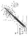
図1は、本発明の生体内組織閉鎖装置の第1実施形態を示す断面図、図2は、図1に示す生体内組織閉鎖装置の生体内組織閉鎖具を示す斜視図、図3は、図1および図2に示す生体内組織閉鎖具の結び目の一例を示した説明図、図4は、図1および図2に示す生体内組織閉鎖具の結び目の他例を示した説明図、図5は、図1および図2に示す生体内組織閉鎖装置の作用(動作)を説明するための斜視図、図6〜図13は、それぞれ、図1に示す生体内組織閉鎖装置の作用(動作)を説明するための断面図である。 1 is a cross-sectional view showing a first embodiment of the in-vivo tissue closing device of the present invention, FIG. 2 is a perspective view showing an in-vivo tissue closing device of the in-vivo tissue closing device shown in FIG. 1, and FIG. FIG. 4 is an explanatory diagram showing an example of the knot of the in-vivo tissue closure shown in FIGS. 1 and 2, and FIG. 4 is an explanatory diagram showing another example of the knot of the in-vivo tissue closure shown in FIG. 1 and FIG. 5 is a perspective view for explaining the operation (operation) of the in-vivo tissue closing device shown in FIGS. 1 and 2, and FIGS. 6 to 13 are respectively the operations (operations) of the in-vivo tissue closing device shown in FIG. It is sectional drawing for demonstrating.
なお、図1では、ストッパー12については、その斜視図も示されている。また、図5において、プッシャーチューブ7は、破線で、模式的に示されている。 In FIG. 1, a perspective view of the
また、説明の都合上、図1、図6〜図12において、図中の左下側を「先端」、右上側(手元側)を「基端」、図2〜図5、図13において、図中の上側を「基端」、下側を「先端」として説明する。 For convenience of explanation, in FIGS. 1 and 6 to 12, the lower left side in the figure is “tip”, the upper right side (hand side) is “base end”, and FIGS. In the following description, the upper side is the “base end” and the lower side is the “tip”.
これらの図に示す生体内組織閉鎖装置1は、例えば、血管等の生体管腔、生体内部器官、生体内部組織等の生体内組織膜に形成され、経皮的に貫通した傷穴(生体内組織膜を貫通する傷穴)を閉じる(閉鎖する)装置である。 The in-vivo tissue closing device 1 shown in these drawings is formed in a living tissue membrane such as a living body lumen such as a blood vessel, a living body internal organ, or a living body internal tissue, and percutaneously penetrates a wound (in vivo This is a device for closing (closing) a wound hole penetrating the tissue membrane.
図1および図2に示すように、生体内組織閉鎖装置1は、長尺状の本体部2と、本体部2の先端部に着脱自在に装着(保持)され、生体内組織膜を貫通する傷穴を閉じる生体内組織閉鎖具であるクリップ4と、クリップ4を牽引する牽引手段である糸(第2の糸状体)8とを備えている。 As shown in FIGS. 1 and 2, the in-vivo tissue closing device 1 is detachably attached (held) to the elongated main body 2 and the distal end of the main body 2 and penetrates the in-vivo tissue membrane. A
本体部2は、中心部に軸線方向に貫通する貫通孔51を有するシース5と、シース5に着脱自在に装着される(シース5内に挿入される)長尺状の配置装置(移送・変形手段)3とを備えている。止血作業(傷穴を閉じる作業)の際は、これらシース5および配置装置3の先端部と、クリップ4とが、それぞれ、傷穴を貫通する。すなわち、傷穴から血管等の生体の管腔(生体管腔)内に挿入される。 The main body 2 includes a
シース5は、略円筒状をなし、その基端部にハブ52を有している。また、ハブ52の内周側には、図示しない止血弁が設置されている。 The
このシース5としては、例えば、カテーテルを用いた治療(PCI)や診断(CAG)の処置後に留置されているシース(イントロデューサシース)を用いてもよく、また、この生体内組織閉鎖装置1専用のものであってもよい。 As the
なお、本実施形態では、本体部2の構成要素にシース5が含まれているが、本発明では、本体部2の構成要素にシース5が含まれていなくてもよい。 In the present embodiment, the
配置装置3は、長尺状の管状部材である外套チューブ(筒状部材)6と、外套チューブ6に着脱自在に装着される(外套チューブ6内に挿入される)長尺状の管状部材であるプッシャーチューブ(筒状部材)7と、キャップ(糸保持部材)9と、キャップ(位置確認用ポート閉鎖部材)13と、ストッパー12とを有している。この配置装置3のうち、外套チューブ6およびプッシャーチューブ7により、クリップ4を移送する移送手段と、後述するクリップ4の糸46の結び目461を移動させることにより、糸46を締め付けて変形部42を変形させる変形手段との主要部が構成される。 The placement device 3 is a mantle tube (cylindrical member) 6 that is a long tubular member, and a long tubular member that is detachably attached to the mantle tube 6 (inserted into the mantle tube 6). A pusher tube (tubular member) 7, a cap (thread holding member) 9, a cap (position confirmation port closing member) 13, and a
外套チューブ6は、チューブ本体61と、チューブ本体61の基端部に設けられたハブ62とで構成され、この外套チューブ6の先端部には、クリップ4が着脱自在に装着(保持)される。この場合、外套チューブ6の先端部の管腔内にクリップ4の後述する変形部42が保持されることにより、そのクリップ4が装着される。 The outer tube 6 includes a tube main body 61 and a
ハブ62は、その先端側に、円筒状の筒状部621を有し、基端側に、円筒状の筒状部622を有している。このハブ362の筒状部621には、シース5のハブ52が嵌合し、筒状部622には、後述するプッシャーチューブ7のハブ72の筒状部721が嵌合する。 The
また、ハブ62には、ハブ62を貫通してチューブ本体61の管腔に連通する貫通孔を有する流出口(位置確認用ポート)623が設けられている。この流出口623には、キャップ13が、着脱自在に装着される。このキャップ13は、頭部を有するピン状をなしており、流出口623内に挿入されることにより、流出口623に装着され、これにより流出口623が閉鎖される。 Further, the
一方、チューブ本体61の先端部には、そのチューブ本体61の管腔に連通する開口(流入口)611が形成されており、この開口611からチューブ本体61の管腔内に流入した体液(血液)は、チューブ本体61の管腔内の内面とプッシャーチューブ7の外面に形成されている図示しない溝とで画成(形成)される流路内を流通して流出口623から流出し得るように構成されている。 On the other hand, an opening (inlet) 611 communicating with the lumen of the tube main body 61 is formed at the distal end portion of the tube main body 61, and body fluid (blood) flowing into the lumen of the tube main body 61 from the opening 611. ) Flows through the flow path defined (formed) by the inner surface in the lumen of the tube main body 61 and the groove (not shown) formed in the outer surface of the
また、外套チューブ6の長さは、シース5より長く設定されている。すなわち、後述するように、配置装置3(外套チューブ6)をシース5の基端側からシース5の貫通孔51に挿入して、外套チューブ6のハブ62とシース5のハブ52とを嵌合させたとき、シース5の先端から外套チューブ6の先端部(開口611を含む部分)が露出するようになっている(シース5の先端が外套チューブ6の先端部より基端側に位置するようになっている。 The length of the outer tube 6 is set longer than that of the
プッシャーチューブ7は、チューブ本体71と、チューブ本体71の基端部711に設けられたハブ72とで構成されている。このプッシャーチューブ7は、外套チューブ6の先端部に装着されているクリップ4を外套チューブ6から押し出し、離脱させる機能と、クリップ4の糸46の結び目461を移動させることにより、糸46を締め付けて変形部42を変形させる機能とを有する。
ハブ72は、その先端側に、円筒状の筒状部721を有している。The
The
また、チューブ本体71の基端部711には、糸留め用のキャップ(牽引部固定手段)9が、着脱自在に装着される。このキャップ9は、頭部を有するピン状をなしており、基端部711の管腔内に挿入されることにより、その基端部711に装着される。 Further, a cap (traction portion fixing means) 9 for thread fastening is detachably attached to the
糸8を基端部711の管腔内から外部に引き出して、キャップ9を基端部711に装着することにより、糸8がキャップ9と基端部711とで挟み込まれ、保持される。これにより、糸8がプッシャーチューブ7の基端部711に固定される。また、この糸8の一端には、球状のストッパー47が固定されている。 By pulling the
また、ストッパー12は、プッシャーチューブ7のチューブ本体71に対し、着脱自在に装着される。 The
ストッパー12は、略C字状の取付部121と、把持部122とで構成されている。このストッパー12は、プッシャーチューブ7のチューブ本体71を取付部121に挿通させることにより、ハブ72の近傍のチューブ本体71に装着され、そのハブ72と、外套チューブ6のハブ62との間に配置される。 The
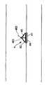
図2に示すように、クリップ(生体内組織閉鎖具)4は、クリップ本体(生閉鎖具本体)40と、糸(第1の糸状体)46とを有している。 As shown in FIG. 2, the clip (in-vivo tissue closure tool) 4 includes a clip body (raw closure body) 40 and a thread (first filament) 46.
クリップ本体40は、シール部41と、変形可能な変形部42と、シール部41と変形部42とを接続する接続部44とで構成されている。これらシール部41、変形部42および接続部44、すなわち、クリップ本体40は、同一の材料で一体的に形成されているのが好ましい。 The clip
シール部41は、生体内組織膜の一方の面(内面)側から傷穴の周辺部(生体内組織膜の傷穴を含む部分)に密着して傷穴および傷穴の周辺部を覆う平面部(平面)412を有する部材であり、板状をなしている。 The
このシール部41における後述する変形部42が接続された面(図2中上側の面)は、略平面をなしている。 A surface (an upper surface in FIG. 2) to which a later-described
変形部42は、パンタグラフ様形状をなしており、接続部44を介してシール部41の平面部412の略中央に連結(接続)されている。 The deforming
すなわち、変形部42は、シール部41に対して略垂直な方向に伸び、シール部41に対して略平行な方向に縮小した第1の形態と、シール部41に対して略垂直な方向に縮み、シール部41に対して略平行な方向に拡張した第2の形態との間において変形可能である枠状をなしている。従って、この変形部42は、図2に示す基本形態(基本形状)から、傷穴を通過可能な形態や、生体内組織膜の他方の面(外面)側からシール部41とで生体内組織膜を挟み、傷穴を閉じることが可能な形態等、前記第1の形態と前記第2の形態との間の任意の形態に変形することができる。 That is, the deforming
生体内組織膜が、血管壁(生体管腔壁)である場合は、前記一方の面は、血管壁(生体管腔壁)の内面であり、前記他方の面は、血管壁(生体管腔壁)の外面である。 When the in-vivo tissue membrane is a blood vessel wall (biological lumen wall), the one surface is an inner surface of the blood vessel wall (biological lumen wall), and the other surface is a blood vessel wall (biological lumen). Wall).
ここで、本実施形態では、変形部42は、帯状体を4回屈曲させて四角形の環状をなす形状(帯状体を複数回屈曲させて多角形の環状をなす形状)としたものである。すなわち、変形部42は、4つのリンクを一体的に形成してなり、ヒンジ状に屈曲可能な4つの角部を有する四角形(四角形の枠状)をなしている。そして、図2中上下方向の対角位置にある2つの角部421、422のうちの図2中下側(シール部41側)の角部422が、接続部44を介してシール部41の平面部412略中央に連結され、接続部44の図2中上側の端部に対して移動不可能な不動部となっている。 Here, in the present embodiment, the deforming
これにより、変形部42は、角部421と角部422とが接近、離間するように変形する、すなわち直行する2方向へ伸縮変形することができ、かつ、シール部41に対し、揺動することもできる。 Accordingly, the
また、2つの角部421、422のうちの図2中上側(シール部41と反対側)の角部421の上面(シール部41と反対側の表面)は、湾曲凸面をなしている。この変形部42の角部421(変形部42のシール部41と反対側の端部)の中央付近には、2つの孔(貫通孔)425および428が形成され、角部422の中央付近には、2つの孔(貫通孔)426および427が形成されている。 Further, of the two
また、接続部44は、板状をなしており、その中央付近には、孔(貫通孔)441が形成されている。この接続部44により、シール部41と変形部42の角部422とを所定距離離間させることができる。 Further, the connecting
糸46は、変形部42のシール部41と反対側の端部側と、変形部42のシール部41側の端部側とに掛けられ、クリップ本体40に取り付けられている。本実施形態では、糸46は、変形部42の角部421(変形部42のシール部41と反対側の端部)および接続部44を貫通した状態で、変形部42の角部421と接続部44とに掛けられている。すなわち、この糸46は、図2中上側から、順次、変形部42の角部421の孔425を挿通(貫通)し、角部422の孔426を挿入し、接続部44の孔441を挿通し、角部422の孔427を挿通し、角部421の孔428を挿通し、その角部421側(変形部42の外側)で、図3または図4に示すような形状の結び目461を形成している。また、結び目461の図2中上側には、糸8が挿通する輪462が形成されている。 The
結び目461は、先端方向(一方向)、すなわち、図2中下方にのみ移動可能な結び方になっており、この結び目461を先端方向に移動させて糸46を締め付けることにより、変形部42が前記第1の形態と前記第2の形態との間の所定の形態に変形し、その状態を保持することができる。糸46が、変形部42前記所定の形態になった状態を保持しているとき、その結び目461は、変形部42のシール部41と反対側の端部、すなわち、角部421に位置する。 The
前記結び目461は、プッシャーチューブ7の内径よりも大きく形成され、また、前記輪462は、プッシャーチューブ7の内径よりも小さく形成されている。これにより、プッシャーチューブ7によって、クリップ4の糸46の結び目461を移動させ、糸46を締め付けて変形部42を変形させる際、輪462は、プッシャーチューブ7の管腔内に入ることができ、また、結び目461がプッシャーチューブ7の管腔内に入ってしまうことを防止することができ、確実に、結び目461を移動させることができる。 The
図1および図2に示すように、糸8は、糸46の輪462を挿通した状態で、プッシャーチューブ7の管腔内を挿通し、その両端部が、プッシャーチューブ7の基端部711から外部に引き出されている。この状態で基端部711にキャップ9を装着することにより、糸8は、キャップ9と基端部711との間で挟まれ(保持され)、基端部711に保持(固定)される。すなわち、糸8は、その一端部にクリップ4が保持され、この状態で、キャップ9により、他端部がプッシャーチューブ7の基端部711に保持(固定)される。 As shown in FIG. 1 and FIG. 2, the
これにより、クリップ4の先端側への移動が阻止(防止)され、外套チューブ6の先端部からのクリップ4の離脱が阻止される。
なお、前記糸46がこの糸8を兼用していてもよい。Thereby, the movement of the
The
前記クリップ4のクリップ本体40の少なくとも一部は、生体吸収性材料で構成されるのが好ましく、特に、クリップ本体40の主要部分(大部分)は、生体吸収性材料で全体を一体的に構成されるのが好ましい。これにより、クリップ本体40の主要部分が所定期間後に生体に吸収され、最終的に生体内に残らないので、人体への影響をなくすことができる。また、糸46も生体吸収性材料で構成されるのが好ましい。 It is preferable that at least a part of the
用いられる生体吸収性材料としては、例えば、ポリ乳酸、ポリグリコール酸、ポリジオキサノン等の単体、あるいはこれらの複合体が挙げられる。 Examples of the bioabsorbable material used include simple substances such as polylactic acid, polyglycolic acid, and polydioxanone, or composites thereof.
なお、クリップ4のクリップ本体40の構成材料としては、生体吸収性材料に限らず、例えば、樹脂や金属等の生体適合性材料を用いることができる。また、糸46の構成材料も生体吸収性材料には限定されない。 In addition, as a constituent material of the clip
また、前記クリップ4のクリップ本体40としては、特に、変形部42の変形機能に求められる材料物性としては、ヒンジ特性に優れたものであることが望ましい。具体的には、引張り強さ250〜500(Kg/cm2)、伸び150〜800%、引張弾性率8〜20(×103Kg/cm2)、曲げ強さ300〜700(Kg/cm2)のものが好ましい。これらの物性値を満たすことによって、クリップ本体40は、ヒンジ特性に優れ、変形部42が所望の変形能を有することができる。 Further, the clip
図11に示すように、クリップ4が外套チューブ6から離脱している状態で、糸8によりクリップ4の糸46を牽引しつつ、クリップ4に対して、配置装置3(本体部2)をその先端方向へ相対的に移動させると、プッシャーチューブ7により結び目461が先端方向へ押され、結び目461が先端方向に移動して、糸46が締め付けられ、変形部42が変形する。 As shown in FIG. 11, while the
この場合、クリップ4が外套チューブ6に装着されているときは、クリップ4の変形部42は、図5(a)に示すように、シール部41に対して略垂直な方向に伸び、シール部41に対して略平行な方向に縮小した形態をなしている。そして、結び目461が先端方向に移動して糸46が締め付けられるにつれて、変形部42の角部421が図5中下側に移動してゆき、その変形部42は、図5(a)に示す形態から、図5(b)に示す形態、図5(c)に示す、シール部41と変形部42で生体内組織膜を挟み、傷穴を閉じることが可能な形態へと、連続的に変形する。すなわち、変形部42は、シール部41に対して略垂直な方向に縮み、シール部41に対して略平行な方向に拡張してゆく。 In this case, when the
また、前述したように、結び目461は、先端方向にのみ移動可能な結び方になっているので、糸46により、変形部42が所定の形態になった状態が保持される。 Further, as described above, the
このように、このクリップ4によれば、変形部42の変形の度合いを連続的に規制(調整)することができる(2つの角部421、422の間の距離を連続的に規制(調整)することができる)。すなわち、変形部42が所望の形態になった状態で、その状態を保持することができる。これにより、例えば、生体内組織膜が厚い人、薄い人、硬い人、軟らかい人等、種々の場合に対応することができる(様々な生体内組織膜の状態(状況)に対応することができる。 As described above, according to the
なお、本発明では、クリップ(生体内組織閉鎖具)の構成は、シール部、変形部および糸(糸状体)を有しているものであれば、前記のものに限定されないことは言うまでもない。 In the present invention, it goes without saying that the configuration of the clip (in vivo tissue closure device) is not limited to the above as long as it has a seal portion, a deformable portion, and a thread (filament).
例えば、本発明では、クリップ(生体内組織閉鎖具)の変形部の形状は、四角形に限らず、他の多角形でもよく、また、円環状、楕円環等の角のない枠状であってもよい。 For example, in the present invention, the shape of the deformed portion of the clip (in vivo tissue closure device) is not limited to a quadrangle, and may be another polygonal shape, or a frame shape having no corners such as an annular shape or an elliptical shape. Also good.
次に、生体内組織閉鎖装置1を用いて行なう止血作業の手順(生体内組織閉鎖装置1の作用)について説明する。 Next, a procedure of hemostasis work performed using the in vivo tissue closing apparatus 1 (operation of the in vivo tissue closing apparatus 1) will be described.
まず、図1に示すように、配置装置3を組み立てる。
この場合、まず、ストッパー12をプッシャーチューブ7のチューブ本体71におけるハブ72の近傍に装着し、そのプッシャーチューブ7を外套チューブ6の基端側から外套チューブ6内に挿入し、プッシャーチューブ7のハブ72と外套チューブ6のハブ62との間にストッパー12を位置させる。First, as shown in FIG. 1, the arrangement device 3 is assembled.
In this case, first, the
次に、糸8の端部をプッシャーチューブ7の基端側からプッシャーチューブ7内に挿入し、その先端部712および外套チューブ6の先端部から外部に引き出す。そして、糸8の端部をクリップ4の糸46の輪462を挿通させ、外套チューブ6およびプッシャーチューブ7の先端側からプッシャーチューブ7内に挿入し、その基端部711から外部に引き出す。 Next, the end portion of the
次に、クリップ4の変形部42を潰して図5(a)に示す形態に変形させ、その変形部42を外套チューブ6の先端側から外套チューブ6内に挿入する(装着する)。 Next, the
次に、糸8の両端部を基端側に向けて適度に引っ張りつつ、キャップ9をプッシャーチューブ7の基端部711の管腔内に挿入し、装着する。これにより、糸8の両端部は、キャップ9と基端部711とで挟み込まれ、基端部711に固定され、糸8の両端部よりも先端側は、プッシャーチューブ7の管腔内に、その管腔に沿って配置される。以上で、配置装置3の組み立てが完了する。なお、配置装置3の組み立ての手順は、これに限定されないことは、言うまでもない。 Next, the
シース5としては、カテーテルを用いた治療(PCI)や診断(CAG)の処置後に留置されているシースを用いる。このシース5の先端部は、血管内に挿入されている。 As the
次に、図1に示すように、配置装置3をシース5の基端側からシース5の貫通孔51に挿入してゆき、図6に示すように、外套チューブ6のハブ62とシース5のハブ52とを嵌合させる。これにより、シース5の先端部から外套チューブ6の先端部が突出するとともに、クリップ4のシール部41が突出し、血管内に挿入される。 Next, as shown in FIG. 1, the placement device 3 is inserted into the through
次に、図7に示すように、本体部2をゆっくり傷穴から引き抜く方向に移動させ、クリップ4のシール部41で血管壁の内側から傷穴および傷穴の周辺部を覆う(シール部41の位置決めを行なう)。クリップ4の変形部42および固定部43は、それぞれ、血管の外側に移動する。 Next, as shown in FIG. 7, the main body portion 2 is slowly moved in the direction of pulling out from the wound hole, and the
なお、術者は、前記シール部41で傷穴および傷穴の周辺部を覆う際の作業(操作)においては、本体部2を傷穴から引き抜く方向に移動させた際、シール部41が傷穴およびその周辺組織に当接したときの抵抗(面当て抵抗)を感知すると、シール部41が傷穴およびその周辺組織に当接し(面当てされ)、シール部41の位置決めが完了したものと判断する。 In addition, in the operation (operation) when the surgeon covers the wound hole and the peripheral portion of the wound hole with the
次に、図8に示すように、外套チューブ6の流出口623に装着されているキャップ13を取り外す。 Next, as shown in FIG. 8, the
流出口623からの血液のバックフラッシュ(フラッシュバック)がないことを確認する。 Make sure there is no blood backflush (flashback) from the
なお、シール部41の位置決めが正しくなされておらず、外套チューブ6の開口611が血管内に位置している場合は、流出口623から血液のバックフラッシュが生じる。この場合は、キャップ13を流出口623に装着して、再度、前記シール部41で傷穴および傷穴の周辺部を覆う作業を行なう。 When the sealing
次に、図9に示すように、外套チューブ6のハブ62とプッシャーチューブ7のハブ72との間にあるストッパー12を取り外し、図10に示すように、外套チューブ6またはシース5を傷穴から引き抜く方向に移動させ、プッシャーチューブ7のハブ72と外套チューブ6のハブ62とを嵌合させる。 Next, as shown in FIG. 9, the
この際、外套チューブ6の先端部に保持されているクリップ4の変形部42は、プッシャーチューブ7により、外套チューブ6から押し出され、離脱する。 At this time, the
次に、図11に示すように、キャップ9をプッシャーチューブ7の基端部711から取り外す。 Next, as shown in FIG. 11, the
次に、図12に示すように、糸8を少し引いてテンションを加えつつ(クリップ4の糸46を牽引しつつ)、本体部2を傷穴内に挿入する方向に押す。これにより、図5(c)に示すように、プッシャーチューブ7によって、結び目461が先端方向へ押され、結び目461が先端方向に移動して、糸46が締め付けられ、変形部42が変形する。この操作を止血が完了するまで続ける。 Next, as shown in FIG. 12, the main body 2 is pushed in the direction of insertion into the wound hole while pulling the
これにより、変形部42が血管壁の外側から傷穴および傷穴の周辺部を覆い、シール部41が血管壁の内側から傷穴および傷穴の周辺部を覆い、これらシール部41と変形部42とで血管壁が挟み込まれ、傷穴が閉じる。そして、糸46により、変形部42が前記の形態になった状態が保持される。 As a result, the deforming
最後に、図13に示すように、本体部2および糸8をそれぞれ抜去し、クリップ4が生体内に配置(留置)される。 Finally, as shown in FIG. 13, the main body 2 and the
なお、糸8の一端にはストッパー47が固定されているので、図5(d)に示すように、本体部2を抜去すると、それと共に糸8も抜去される。以上で、止血作業が完了する。 Since the
以上説明したように、この生体内組織閉鎖装置1によれば、クリップ4の変形部42が第1の形態と第2の形態との間の所望の形態になった状態で、糸46により、その状態を保持することができる。これにより、様々な生体内組織膜の状態(状況)に対応することができ、血管壁等の生体内組織膜に形成された傷穴に対し、止血作業を容易かつ確実に行なうことができる。すなわち、傷穴を容易かつ確実に閉じる(閉鎖する)ことができ、完全に止血することができる。 As described above, according to the in-vivo tissue closing device 1, the
また、変形部42を容易かつ確実に変形させることができ、これにより、仮に止血不良が生じたとしても、そのときは変形部42がシール部41に対して略平行な方向に確実に広がっており、このため、その後、用手圧迫止血を行なうことができ、非常に安全に止血作業を行うことができる。 In addition, the
また、糸8をクリップ4の糸46と別部材で構成しているので、糸を皮下組織内で切断する操作を行なう必要がなく、容易かつ迅速に、止血作業を行なうことができる。 Further, since the
また、クリップ4の糸46は、変形部42の角部421と接続部44とに掛けられているので、その糸46が血管内に入らないという利点がある。 Further, since the
次に、本発明の生体内組織閉鎖装置の第2実施形態について説明する。
図14は、本発明の生体内組織閉鎖装置の第2実施形態における生体内組織閉鎖具を示す斜視図である。Next, a second embodiment of the in vivo tissue closing device of the present invention will be described.
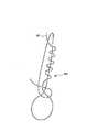
FIG. 14 is a perspective view showing an in-vivo tissue closure device in the second embodiment of the in-vivo tissue closure device of the present invention.
なお、説明の都合上、図14において、図中の上側を「基端」、下側を「先端」として説明する。 For convenience of explanation, in FIG. 14, the upper side in the figure is described as “base end” and the lower side is described as “tip”.
以下、第2実施形態の生体内組織閉鎖装置1について、前述した第1実施形態との相違点を中心に説明し、同様の事項については、その説明を省略する。 Hereinafter, the in-vivo tissue closing device 1 of the second embodiment will be described focusing on the differences from the first embodiment described above, and the description of the same matters will be omitted.
第2実施形態の生体内組織閉鎖装置1では、クリップ(生体内組織閉鎖具)4が、前述した第1実施形態のクリップ4と異なっており、それ以外については、同様である。 In the in-vivo tissue closing device 1 of the second embodiment, the clip (in-vivo tissue closing tool) 4 is different from the above-described
図14に示すように、第2実施形態では、クリップ4の糸46は、変形部42の角部421(変形部42のシール部41と反対側の端部)およびシール部41を貫通した状態で、変形部42の角部421とシール部41とに掛けられている。すなわち、クリップ4のシール部41の中央付近には、接続部44を介して対向する2つの孔(貫通孔)413および414が形成されており、糸46は、図14中上側から、順次、変形部42の角部421の孔425を挿通(貫通)し、角部422の孔426を挿通し、シール部41の孔413を挿通し、シール部41の孔414を挿通し、角部422の孔427を挿通し、角部421の孔428を挿通し、その角部421側(変形部42の外側)で、結び目461を形成している。 As shown in FIG. 14, in the second embodiment, the
この生体内組織閉鎖装置1によれば、前述した第1実施形態の生体内組織閉鎖装置1と同様の効果が得られる。 According to the in-vivo tissue closing device 1, the same effect as the in-vivo tissue closing device 1 of the first embodiment described above can be obtained.
そして、この生体内組織閉鎖装置1では、クリップ4の糸46は、変形部42の角部421とシール部41とに掛けられているので、止血作業の際、接続部44が切断されたとしてもシール部41が血管内を流れていってしまうのを阻止(防止)することができる。 And in this in-vivo tissue closing device 1, since the thread |
また、接続部44には糸46が挿通する孔が形成されていないので、第1実施形態に比べて、接続部44の強度を高くすることができる。 Further, since the hole through which the
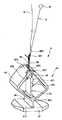
次に、本発明の生体内組織閉鎖装置の第3実施形態について説明する。
図15は、本発明の生体内組織閉鎖装置の第3実施形態における生体内組織閉鎖具を示す斜視図である。Next, a third embodiment of the in vivo tissue closing device of the present invention will be described.
FIG. 15 is a perspective view showing an in-vivo tissue closure device in the third embodiment of the in-vivo tissue closure device of the present invention.
なお、説明の都合上、図15において、図中の上側を「基端」、下側を「先端」として説明する。 For convenience of explanation, in FIG. 15, the upper side in the figure is described as “base end”, and the lower side is described as “tip”.
以下、第3実施形態の生体内組織閉鎖装置1について、前述した第1実施形態との相違点を中心に説明し、同様の事項については、その説明を省略する。 Hereinafter, the in-vivo tissue closing device 1 of the third embodiment will be described focusing on the differences from the first embodiment described above, and the description of the same matters will be omitted.
第3実施形態の生体内組織閉鎖装置1では、クリップ(生体内組織閉鎖具)4が、前述した第1実施形態のクリップ4と異なっており、それ以外については、同様である。 In the in-vivo tissue closing device 1 of the third embodiment, the clip (in-vivo tissue closing tool) 4 is different from the above-described
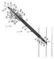
図15に示すように、第3実施形態では、クリップ4の変形部42の角部422の内面(変形部42のシール部41側の内面)に、板状の糸掛け部45が設けられている。糸掛け部45の中央付近には、孔(貫通孔)451が形成されている。また、シール部41、変形部42、接続部44および糸掛け部45、すなわち、クリップ本体40は、同一の材料で一体的に形成されているのが好ましい。 As shown in FIG. 15, in the third embodiment, a plate-
クリップ4の糸46は、変形部42の角部421(変形部42のシール部41と反対側の端部)および糸掛け部45の孔451を貫通した状態で、変形部42の角部421と糸掛け部45とに掛けられている。すなわち、糸46は、図14中上側から、順次、変形部42の角部421の孔425を挿通(貫通)し、糸掛け部45の孔451を挿通し、角部421の孔428を挿通し、その角部421側(変形部42の外側)で、結び目461を形成している。 The
この生体内組織閉鎖装置1によれば、前述した第1実施形態の生体内組織閉鎖装置1と同様の効果が得られる。 According to the in-vivo tissue closing device 1, the same effect as the in-vivo tissue closing device 1 of the first embodiment described above can be obtained.
そして、この生体内組織閉鎖装置1では、クリップ4の糸46は、変形部42の角部421と糸掛け部45とに掛けられており、接続部44には糸46が挿通する孔が形成されていないので、第1実施形態に比べて、接続部44の強度を高くすることができる。 In this in-vivo tissue closing device 1, the
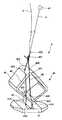
次に、本発明の生体内組織閉鎖装置の第4実施形態について説明する。
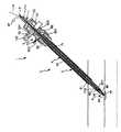
図16は、本発明の生体内組織閉鎖装置の第4実施形態における生体内組織閉鎖具を示す斜視図、図17は、図16に示す生体内組織閉鎖装置の作用(動作)を説明するための斜視図である。
なお、図17において、プッシャーチューブ7は、破線で、模式的に示されている。Next, a fourth embodiment of the in vivo tissue closing device of the present invention will be described.
FIG. 16 is a perspective view showing an in-vivo tissue closing device in a fourth embodiment of the in-vivo tissue closing apparatus of the present invention, and FIG. 17 is a diagram for explaining the operation (operation) of the in-vivo tissue closing apparatus shown in FIG. FIG.
In FIG. 17, the
また、説明の都合上、図16および図17において、図中の上側を「基端」、下側を「先端」として説明する。 For convenience of explanation, in FIGS. 16 and 17, the upper side in the figure is described as “base end” and the lower side is described as “tip”.
以下、第4実施形態の生体内組織閉鎖装置1について、前述した第1実施形態との相違点を中心に説明し、同様の事項については、その説明を省略する。 Hereinafter, the in-vivo tissue closing device 1 according to the fourth embodiment will be described with a focus on differences from the first embodiment described above, and description of similar matters will be omitted.
第4実施形態の生体内組織閉鎖装置1では、クリップ(生体内組織閉鎖具)4およびプッシャーチューブ7が、それぞれ、前述した第1実施形態のクリップ4およびプッシャーチューブ7と異なっており、それ以外については、同様である。 In the in vivo tissue closing device 1 of the fourth embodiment, the clip (in vivo tissue closing tool) 4 and the
図16および図17に示すように、第4実施形態では、クリップ4のクリップ本体40は、シール部41と、変形部42と、シール部41と変形部42とを接続する接続部44と、変形部42が第1の形態と第2の形態との間の所定の形態になった状態で、変形部に係合してその状態を保持する固定部43とで構成されている。これらシール部41、変形部42、接続部44および固定部43、すなわち、クリップ本体40は、同一の材料で一体的に形成されているのが好ましい。 As shown in FIGS. 16 and 17, in the fourth embodiment, the
変形部42の角部421(変形部42のシール部41と反対側の端部)には、略H字状のスリット424が形成されている。スリット424は、枠状の変形部42を貫通した開口部であり、後述する固定部43の少なくとも一部が挿入(挿通)可能なようになっている。 A substantially H-shaped
固定部43は、板状(棒状)をなしている。この固定部43は、変形部42の枠内に位置し、その図16中下側の端部が、角部422の内面に連結されている。これにより、固定部43は、シール部41に対し、変形部42とともに揺動することができる。 The fixing
また、固定部43の図16中左右方向の片側(右側)には、爪431が形成されている。この爪431は、固定部43の長手方向(図16中上下方向)に沿って、所定間隔で複数個(図示例では、2つ)並設されている。 Further, a
また、固定部43の図16中上側の端部(固定部43のシール部41と反対側の端部)の中央付近には、孔(貫通孔)432が形成されている。 Further, a hole (through hole) 432 is formed in the vicinity of the center of the upper end portion in FIG. 16 of the fixing portion 43 (the end portion of the fixing
図16に示すように、固定部43がスリット424に挿入されていないときは、クリップ4の糸46は、変形部42の角部421のスリット424および固定部43の孔432を貫通した状態で、変形部42の角部421(変形部42のシール部41と反対側の端部)と固定部43とに掛けられている。すなわち、糸46は、図16中上側から、順次、変形部42の角部421のスリット424を挿通(貫通)し、固定部43の孔431を挿通し、角部421のスリット424を挿通し、その角部421側(変形部42の外側)で、結び目461を形成している。この結び目461は、スリット424の間隙(図16中左右方向の長さ)よりも大きく形成されている。 As shown in FIG. 16, when the fixing
一方、図17に示すように、プッシャーチューブ7の先端部712の管腔の内径は、先端部712より基端側の部位の管腔の内径よりも大きく設定されている。この先端部712の管腔の内径は、クリップ4の固定部43よりも大きい。 On the other hand, as shown in FIG. 17, the inner diameter of the lumen of the
ここで、このクリップ4では、変形部43の第1の形態と第2の形態との間の変形の度合いに応じて、糸46による保持と、固定部43による保持とに分けられている。すなわち、変形部42の第1の形態を基準にして、変形部42の変形の度合いが小さい領域では、糸46により、変形部42が所定の形態になった状態を保持し、変形部42の変形の度合いが大きい領域では、固定部43により、変形部42が所定の形態になった状態を保持するように構成されている。以下、具体的に説明する。 Here, the
クリップ4が外套チューブ6から離脱している状態で、糸8によりクリップ4の糸46を牽引しつつ、クリップ4に対して、配置装置3(本体部2)をその先端方向へ相対的に移動させると、プッシャーチューブ7の先端部712が図17中上側から変形部42の角部421の上面423に当接するとともに、プッシャーチューブ7により結び目461が先端方向へ押され、結び目461が先端方向に移動して、糸46が締め付けられ、変形部42が変形する。 While the
この場合、クリップ4が外套チューブ6に装着されているときは、クリップ4の変形部42は、図17(a)に示すように、シール部41に対して略垂直な方向に伸び、シール部41に対して略平行な方向に縮小した形態をなしている。そして、結び目461が先端方向に移動して糸46が締め付けられるにつれて、変形部42の角部421が図17中下側に移動してゆき、その変形部42は、図17(a)に示す形態から、図5(b)に示す形態へと、連続的に変形する。また、結び目461は、先端方向にのみ移動可能な結び方になっているので、糸46により、変形部42が所定の形態になった状態が保持される。 In this case, when the
そして、糸8によりクリップ4の糸46を牽引しつつ、クリップ4に対して、さらに、配置装置3(本体部2)をその先端方向へ相対的に移動させると、プッシャーチューブ7により、変形部42の角部421が図17中下側に向って押圧される。このとき、固定部43は、プッシャーチューブ7の管腔内に位置し、邪魔にはならない(図17(c)参照)。 Then, while pulling the
これにより、図17(c)に示すように、変形部42の角部421が図17中下側に移動し、固定部43の図17中上側の端部および固定部43の図17中上側の爪431は、角部421に形成されているスリット424を挿通し(スリット424に挿入され)、その爪431が角部421に係合する。この際、変形部43の内側に位置する糸46は、固定部43の孔432と共に、スリット424から変形部43の外側に移動する。 As a result, as shown in FIG. 17C, the
この状態でプッシャーチューブ7による押圧を解除しても、固定部43により、変形部42が所定の形態になった状態が変形部42の形状は保持される。また、変形部42の角部421が図17中上側に向って押圧されても、固定部43により、変形部42が所定の形態になった状態が保持される。 Even if the pressing by the
クリップ4に対して、さらに、配置装置3(本体部2)をその先端方向へ相対的に移動させると、プッシャーチューブ7により、変形部42の角部421が図17中下側に向ってさらに押圧される。 When the placement device 3 (main body portion 2) is further moved relative to the
これにより、変形部42の角部421が図17中下側にさらに移動し、固定部43の図17中下側の爪431は、角部421に形成されているスリット424を挿通し(スリット424に挿入され)、その爪431が角部421に係合する。 As a result, the
前記と同様に、この状態でプッシャーチューブ7による押圧を解除しても、固定部43により、変形部42が所定の形態になった状態が保持される。 Similarly to the above, even if the pressing by the
この生体内組織閉鎖装置1によれば、前述した第1実施形態の生体内組織閉鎖装置1と同様の効果が得られる。 According to the in-vivo tissue closing device 1, the same effect as the in-vivo tissue closing device 1 of the first embodiment described above can be obtained.
そして、この生体内組織閉鎖装置1では、固定部43により、変形部42が所定の形態になった状態を保持することができるので、第1実施形態に比べて、変形部42が所定の形態になった状態を強固に保持することができる。 And in this in-vivo tissue closing device 1, since the deformation |
また、固定部43の爪431が変形部42の角部421に係合し得る形態まで変形部42が変形できない(変形しない)場合でも、糸8により、変形部42が所定の形態になった状態を保持することができる。 Further, even when the
また、クリップ4の糸46は、変形部42の角部421と固定部45とに掛けられており、接続部44には糸46が挿通する孔が形成されていないので、第1実施形態に比べて、接続部44の強度を高くすることができる。 Further, the
なお、本発明では、クリップ(生体内組織閉鎖具)の固定部の爪の数は、1つでもよく、また、3つ以上でもよい。 In the present invention, the number of claws of the fixing part of the clip (in vivo tissue closure device) may be one, or may be three or more.
次に、本発明の生体内組織閉鎖装置の第5実施形態について説明する。
図18および図19は、それぞれ、本発明の生体内組織閉鎖装置の第5実施形態を示す斜視図である。Next, a fifth embodiment of the in vivo tissue closing device of the present invention will be described.
18 and 19 are perspective views showing a fifth embodiment of the in-vivo tissue closing device of the present invention, respectively.
なお、図18および図19において、プッシャーチューブ7は、破線で、模式的に示されている。また、糸46の結び目461は、強く結んでいない状態が示されている。 18 and 19, the
また、説明の都合上、図18および図19において、図中の上側を「基端」、下側を「先端」として説明する。 For convenience of explanation, in FIGS. 18 and 19, the upper side in the drawing is described as “base end” and the lower side is described as “tip”.
以下、第5実施形態の生体内組織閉鎖装置1について、前述した第1実施形態との相違点を中心に説明し、同様の事項については、その説明を省略する。 Hereinafter, the in-vivo tissue closure device 1 of the fifth embodiment will be described focusing on the differences from the first embodiment described above, and description of similar matters will be omitted.
第5実施形態の生体内組織閉鎖装置1では、クリップ(生体内組織閉鎖具)4の糸(第1の糸状体)46および糸(第2の糸状体)8が、それぞれ、前述した第1実施形態のクリップ4の糸46および糸8と異なり、さらに糸ロック部材(固定具)14が設けられていること以外については、同様である。 In the in vivo tissue closing device 1 of the fifth embodiment, the thread (first filament) 46 and the thread (second filament) 8 of the clip (in vivo tissue closure tool) 4 are respectively the first described above. Unlike the
図18および図19に示すように、第5実施形態では、クリップ4の糸(第1の糸状体)46は、1本の糸(糸状体)を折り返してなり、一方の端部が折り返し部463となる二重糸(二重糸状体)で構成され、その折り返し部463により、輪462が形成されている。そして、第1実施形態と同様に、折り返し部463(輪462)とシール部41との間に変形部42が位置するような関係に配置されている。 As shown in FIG. 18 and FIG. 19, in the fifth embodiment, the thread (first thread-like body) 46 of the
糸(第2の糸状体)8は、1本の糸(糸状体)を折り返してなり、一方の端部が折り返し部81となる二重糸(二重糸状体)で構成されている。糸8の他方の端部には、円筒状のストッパー47が固定されている。ストッパー47の固定方法としては、例えば、接着、かしめ等が挙げられる。この糸8により、生体内組織閉鎖具4が着脱自在に保持される。また、ストッパー47により、糸8の折り返し部81と反対側の端部が、プッシャーチューブ7の管腔内に進入してしまうのを阻止(防止)することができる。 The thread (second thread-like body) 8 is formed of a double thread (double thread-like body) formed by folding one thread (thread-like body) and having one end portion serving as a folded
糸ロック部材(固定具)14は、図19(c)に示すように、頭部を有する線状体で構成されており、図18(a)および(b)に示すように、屈曲または湾曲した形状に弾性変形することができるようになっている。この糸ロック部材14は、例えば、樹脂材料等で形成することができる。 The thread lock member (fixing tool) 14 is formed of a linear body having a head as shown in FIG. 19 (c), and is bent or curved as shown in FIGS. 18 (a) and 18 (b). It can be elastically deformed to the shape. The
図18(a)および(b)に示すように、前記糸8の折り返し部81は、プッシャーチューブ7の基端部711に位置している。そして、前記糸ロック部材14は、糸8の折り返し部81に引っ掛けられ、屈曲または湾曲した状態で、プッシャーチューブ7の基端部711に配置されている。なお、糸ロック部材14の頭部側および先端側は、それぞれ、プッシャーチューブ7の外側に位置している。 As shown in FIGS. 18A and 18B, the folded
止血作業において、変形部42を変形させる際は、図18(b)に示すように、ストッパー47を手指で把持し、そのストッパー47(糸8)を少し引いてテンションを加えつつ(クリップ4の糸46を牽引しつつ)、プッシャーチューブ7(本体部2)を傷穴内に挿入する方向に押す。この際、糸ロック部材14により、糸8の折り返し部81が、プッシャーチューブ7の管腔内を、先端方向へ向って移動するのを阻止(防止)することができ、これにより、クリップ4の糸46を確実に牽引することができる。 In the hemostasis operation, when the deforming
本体部2および糸8をそれぞれ抜去する際は、図18(c)に示すように、糸ロック部材14を取り外し、図18(d)に示すように、プッシャーチューブ7(本体部2)を抜去すると、それと共に糸8も抜去される。 When removing the main body 2 and the
この生体内組織閉鎖装置1によれば、前述した第1実施形態の生体内組織閉鎖装置1と同様の効果が得られる。 According to the in-vivo tissue closing device 1, the same effect as the in-vivo tissue closing device 1 of the first embodiment described above can be obtained.
そして、この生体内組織閉鎖装置1では、糸46の折り返し部463により輪462が形成されるので、糸46に対して、結び目461とは別の結び目を形成し、その結び目を輪として用いる場合に比べ、クリップ4を組み立てる作業や、プッシャーチューブ7により結び目461を押して変形部42を変形させる操作を容易かつ迅速に行なうこができる。その理由は、結び目461とは別の結び目を形成して輪として用いる場合は、止血作業において、変形部42を変形させる際、プッシャーチューブ7によって、その輪を構成する結び目は押さずに、結び目461のみを押す必要があるので、条件が非常に厳しくなるためである。 In this in-vivo tissue closing device 1, since the
また、糸8を抜去する際、糸8の折り返し部81側は、一旦、生体内に入り込む場合があるが、この生体内組織閉鎖装置1では、糸8の折り返し部81およびその近傍の部位をプッシャーチューブ7の管腔内に位置させることができ、無菌状態に保持することができ、非常に安全に止血作業を行うことができる。 Further, when the
また、この生体内組織閉鎖装置1では、糸46に対して、結び目461とは別の結び目を形成し、その結び目を輪として用いる場合に比べ、糸8を抜去する際、その糸8が円滑に糸46の輪462を通過することができ、また、糸46の輪462が円滑にプッシャーチューブ7の管腔内を移動することができる。 Further, in this in-vivo tissue closing device 1, compared to the case where a knot different from the
なお、この第5実施形態は、前記第2〜第4実施形態にもそれぞれ適用することができる。 The fifth embodiment can also be applied to the second to fourth embodiments.
以上、本発明の生体内組織閉鎖具および生体内組織閉鎖装置を、図示の実施形態に基づいて説明したが、本発明はこれに限定されるものではなく、各部の構成は、同様の機能を有する任意の構成のものに置換することができる。また、本発明に、他の任意の構成物が付加されていてもよい。 As mentioned above, although the in-vivo tissue closure tool and in-vivo tissue closure device of this invention were demonstrated based on embodiment of illustration, this invention is not limited to this, The structure of each part has the same function. It can be replaced with one having any structure. In addition, any other component may be added to the present invention.
また、本発明は、前記各実施形態のうちの、任意の2以上の構成(特徴)を組み合わせたものであってもよい。 Further, the present invention may be a combination of any two or more configurations (features) of the above embodiments.
また、前記実施形態では、変形部42は、パンタグラフ様形状、すなわち、シール部41に対して略垂直な方向に伸び、シール部41に対して略平行な方向に縮小した第1の形態と、シール部41に対して略垂直な方向に縮み、シール部41に対して略平行な方向に拡張した第2の形態との間において変形可能である枠状をなしているが、本発明では、変形部は、これに限らず、シール部に対して略垂直な方向に細長く伸びた形態(第1の形態)と、この形態(第1の形態)からシール部に向かって圧縮された形態(第2の形態)へ変形可能なものであればよい。すなわち、変形部としては、前記実施形態の他、例えば、樹脂材料(合成樹脂材料)を主材料とするスポンジ状の多孔質体(多孔質材料)等で構成することができる。 In the embodiment, the
1 生体内組織閉鎖装置
2 本体部
3 配置装置
4 クリップ
40 クリップ本体
41 シール部
412 平面部
413、414 孔
42 変形部
421、422 角部
423 上面
424 スリット
425〜428 孔
43 固定部
431 爪
432 孔
44 接続部
441 孔
45 糸掛け部
451 孔
46 糸
461 結び目
462 輪
463 折り返し部
47 ストッパー
5 シース
51 貫通孔
52 ハブ
6 外套チューブ
61 チューブ本体
611 開口
62 ハブ
621、622 筒状部
623 流出口
7 プッシャーチューブ
71 チューブ本体
711 基端部
712 先端部
72 ハブ
721 筒状部
8 糸
81 折り返し部
9 キャップ
12 ストッパー
121 取付部
122 把持部
13 キャップ
14 糸ロック部材
DESCRIPTION OF SYMBOLS 1 Biological tissue closure apparatus 2 Main body part 3
Claims (27)
Translated fromJapanese前記生体内組織膜の一方の面側から前記傷穴および前記傷穴の周辺部を覆う板状のシール部と、
前記シール部に対して略垂直な方向に伸び、前記シール部に対して略平行な方向に縮小した第1の形態と、前記シール部に対して略垂直な方向に縮み、前記シール部に対して略平行な方向に拡張した第2の形態との間において変形可能である枠状をなす変形部と、
前記変形部が前記第1の形態と前記第2の形態との間の所定の形態になった状態で、その状態を保持する糸状体と、
前記シール部と前記変形部を接続する接続部とを有し、
前記接続部が板状であることを特徴とする生体内組織閉鎖具。An in-vivo tissue closure device for closing a wound penetrating in-vivo tissue membrane,
A plate-like seal portion covering the wound hole and the peripheral portion of the wound hole from one surface side of the in vivo tissue membrane;
A first form that extends in a direction substantially perpendicular to the seal portion and contracts in a direction substantially parallel to the seal portion; and contracts in a direction substantially perpendicular to the seal portion, with respect to the seal portion A deformable portion having a frame shape that is deformable between the second form expanded in a substantially parallel direction,
In a state where the deforming portion is in a predetermined form between the first form and the second form, a filament that holds the state;
Have aconnecting portion for connecting the flexible portion and the sealingportion,
The in-vivo tissue closure tool,wherein the connecting portion is plate-shaped .
前記固定部は、該固定部が前記開口部に挿入された状態で前記変形部と係合し得る少なくとも一つの爪を有する請求項13ないし16のいずれかに記載の生体内組織閉鎖具。The deformation part has an opening part into which at least a part of the fixing part can be inserted,
The in-vivo tissue closure device according to any one of claims13 to16 , wherein the fixing portion has at least one nail that can be engaged with the deformable portion in a state in which the fixing portion is inserted into the opening.
前記固定部は、該固定部が前記開口部に挿入された状態で前記変形部と係合し得る少なくとも一つの爪と、該固定部の前記シール部と反対側の端部に設けられた孔とを有し、
前記固定部が前記開口部に挿入されていないときは、前記糸状体は、前記変形部の開口部および前記固定部の孔を貫通した状態で、前記変形部の前記シール部と反対側の端部と前記固定部とに掛けられている請求項13ないし16のいずれかに記載の生体内組織閉鎖具。At the end of the deformable portion on the opposite side to the seal portion, an opening into which at least a part of the fixed portion can be inserted is provided,
The fixing portion includes at least one claw that can be engaged with the deformation portion in a state where the fixing portion is inserted into the opening, and a hole provided in an end portion of the fixing portion opposite to the seal portion. And
When the fixing portion is not inserted into the opening, the filamentous body passes through the opening of the deforming portion and the hole of the fixing portion, and the end of the deforming portion on the opposite side to the seal portion. The in-vivo tissue closure device according to any one of claims13 to16 , which is hung on a part and the fixing part.
前記生体内組織膜を一方の面側から前記傷穴および前記傷穴の周辺部を覆うシール部と、
前記シール部に対して略垂直な方向に細長く伸びた第1の形態と、該第1の形態から前記シール部に向かって圧縮された第2の形態へ変形可能な変形部と、
前記変形部が前記第1の形態と前記第2の形態との間の所定の形態になった状態で、その状態を保持する第1の糸状体と、
前記シール部と前記変形部を接続する接続部とを有し、
前記接続部が板状であり、
前記第1の糸状体は、その一方の端部が折り返し部となる二重糸で構成され、該折り返し部と前記シール部との間に前記変形部が位置するような関係に配置され、前記折り返し部により輪が形成されることを特徴とする生体内組織閉鎖具。An in-vivo tissue closure device for closing a wound penetrating in-vivo tissue membrane,
A seal part that covers the wound hole and the peripheral part of the wound hole from one surface side of the in vivo tissue membrane;
A first form elongated in a direction substantially perpendicular to the seal part, and a deformable part deformable from the first form into a second form compressed toward the seal part,
In a state where the deforming portion is in a predetermined form between the first form and the second form, a first filament that holds the state;
Have aconnecting portion for connecting the flexible portion and the sealingportion,
The connecting portion is plate-shaped,
The first thread-like body is composed of a double thread whose one end is a folded portion, and is arranged in such a relationship that the deformed portion is positioned between the folded portion and the seal portion, An in vivo tissue closure device, wherein a ring is formed by a folded portion.
先端部において前記生体内組織閉鎖具を着脱自在に保持する長尺状の配置装置とを有し、
前記生体内組織閉鎖具を生体内に配置し、該生体内組織閉鎖具により生体内組織膜を貫通する傷穴を閉じることを特徴とする生体内組織閉鎖装置。An in vivo tissue closure device according to any one of claims 1 to23 ;
An elongated arrangement device that detachably holds the in-vivo tissue closure device at the distal end portion;
An in vivo tissue closure device, wherein the in vivo tissue closure device is disposed in a living body, and a wound hole penetrating the in vivo tissue membrane is closed by the in vivo tissue closure device.
先端部において前記生体内組織閉鎖具を着脱自在に保持する長尺状の配置装置とを有し、
前記生体内組織閉鎖具を生体内に配置し、該生体内組織閉鎖具により生体内組織膜を閉じる生体内組織閉鎖装置であって、
前記第1の糸状体の前記折り返し部により形成される輪を挿通する第2の糸状体を有し、該第2の糸状体により、前記生体内組織閉鎖具が着脱自在に保持されることを特徴とする生体内組織閉鎖装置。In vivo tissue closure device according to claim21 ,
An elongated arrangement device that detachably holds the in-vivo tissue closure device at the distal end portion;
An in-vivo tissue closure device that disposes the in-vivo tissue closure device in a living body and closes the in-vivo tissue membrane with the in-vivo tissue closure device,
A second thread-like body that is inserted through a ring formed by the folded portion of the first thread-like body, and the second thread-like body holds the biological tissue closure device in a detachable manner. An in-vivo tissue closing device.
前記第2の糸状体の前記折り返し部は、前記配置装置の基端部に位置し、該折り返し部が、前記配置装置の前記管腔内を、先端方向へ向って移動するのを阻止する固定具を有する請求項26に記載の生体内組織閉鎖装置。The arrangement device is provided along a longitudinal direction thereof, and has a lumen through which the second filamentous body is inserted.
The folded portion of the second filament is located at the proximal end of the placement device, and the fixed portion prevents the folded portion from moving in the distal direction in the lumen of the placement device. The in-vivo tissue closure device according to claim26 , further comprising a tool.
Priority Applications (5)
| Application Number | Priority Date | Filing Date | Title |
|---|---|---|---|
| JP2004366780AJP4366306B2 (en) | 2004-12-17 | 2004-12-17 | In vivo tissue closure device and in vivo tissue closure device |
| AT05027557TATE425704T1 (en) | 2004-12-17 | 2005-12-15 | DEVICE FOR CLOSING AN OPENING IN A TISSUE |
| DE602005013342TDE602005013342D1 (en) | 2004-12-17 | 2005-12-15 | Device for closing an opening in a tissue |
| EP05027557AEP1671591B1 (en) | 2004-12-17 | 2005-12-15 | Apparatus for closing an opening in a tissue |
| US11/304,704US7875052B2 (en) | 2004-12-17 | 2005-12-16 | Tissue closure and tissue closing device |
Applications Claiming Priority (1)
| Application Number | Priority Date | Filing Date | Title |
|---|---|---|---|
| JP2004366780AJP4366306B2 (en) | 2004-12-17 | 2004-12-17 | In vivo tissue closure device and in vivo tissue closure device |
Publications (2)
| Publication Number | Publication Date |
|---|---|
| JP2006167311A JP2006167311A (en) | 2006-06-29 |
| JP4366306B2true JP4366306B2 (en) | 2009-11-18 |
Family
ID=35708781
Family Applications (1)
| Application Number | Title | Priority Date | Filing Date |
|---|---|---|---|
| JP2004366780AExpired - Fee RelatedJP4366306B2 (en) | 2004-12-17 | 2004-12-17 | In vivo tissue closure device and in vivo tissue closure device |
Country Status (5)
| Country | Link |
|---|---|
| US (1) | US7875052B2 (en) |
| EP (1) | EP1671591B1 (en) |
| JP (1) | JP4366306B2 (en) |
| AT (1) | ATE425704T1 (en) |
| DE (1) | DE602005013342D1 (en) |
Families Citing this family (96)
| Publication number | Priority date | Publication date | Assignee | Title |
|---|---|---|---|---|
| US7662161B2 (en) | 1999-09-13 | 2010-02-16 | Rex Medical, L.P | Vascular hole closure device |
| US9861346B2 (en) | 2003-07-14 | 2018-01-09 | W. L. Gore & Associates, Inc. | Patent foramen ovale (PFO) closure device with linearly elongating petals |
| EP2481356B1 (en) | 2003-07-14 | 2013-09-11 | W.L. Gore & Associates, Inc. | Tubular patent foramen ovale (PFO) closure device with catch system |
| US8480706B2 (en) | 2003-07-14 | 2013-07-09 | W.L. Gore & Associates, Inc. | Tubular patent foramen ovale (PFO) closure device with catch system |
| CA2551531C (en)* | 2003-12-26 | 2015-02-24 | Terumo Kabushiki Kaisha | Tissue closure and tissue closing device |
| EP1748732A1 (en) | 2004-05-07 | 2007-02-07 | NMT Medical, Inc. | Catching mechanisms for tubular septal occluder |
| US20050267520A1 (en)* | 2004-05-12 | 2005-12-01 | Modesitt D B | Access and closure device and method |
| US7678133B2 (en)* | 2004-07-10 | 2010-03-16 | Arstasis, Inc. | Biological tissue closure device and method |
| CN103190942A (en) | 2005-05-12 | 2013-07-10 | 阿尔斯塔西斯公司 | Access and closure device and method |
| JP4955328B2 (en) | 2005-09-29 | 2012-06-20 | テルモ株式会社 | In vivo tissue closure device |
| GB2447400B (en) | 2006-01-31 | 2011-11-02 | Cook Biotech Inc | Fistula grafts and related methods and systems for treating fistulae |
| CA2662901A1 (en) | 2006-06-21 | 2007-12-27 | Cook Incorporated | Fistula grafts and related methods and systems useful for treating gastrointestinal fistulae |
| WO2008036384A2 (en)* | 2006-09-21 | 2008-03-27 | Synecor, Llc | Stomach wall closure devices |
| US9005242B2 (en) | 2007-04-05 | 2015-04-14 | W.L. Gore & Associates, Inc. | Septal closure device with centering mechanism |
| US8535349B2 (en) | 2007-07-02 | 2013-09-17 | Cook Biotech Incorporated | Fistula grafts having a deflectable graft body portion |
| EP2166954A1 (en)* | 2007-07-13 | 2010-03-31 | Rex Medical, L.P. | Vascular hole closure device |
| US9113851B2 (en) | 2007-08-23 | 2015-08-25 | Cook Biotech Incorporated | Fistula plugs and apparatuses and methods for fistula plug delivery |
| US9456816B2 (en) | 2007-09-12 | 2016-10-04 | Transluminal Technologies, Llc | Closure device, deployment apparatus, and method of deploying a closure device |
| JP5426553B2 (en) | 2007-09-12 | 2014-02-26 | トランスルミナル テクノロジーズ リミテッド ライアビリティー カンパニー | Closure device, placement device, and method of placing a closure device |
| US8876861B2 (en)* | 2007-09-12 | 2014-11-04 | Transluminal Technologies, Inc. | Closure device, deployment apparatus, and method of deploying a closure device |
| US20090105744A1 (en)* | 2007-10-17 | 2009-04-23 | Modesitt D Bruce | Methods for forming tracts in tissue |
| US9492149B2 (en) | 2007-11-13 | 2016-11-15 | Cook Biotech Incorporated | Fistula grafts and related methods and systems useful for treating gastrointestinal and other fistulae |
| JP2009148442A (en)* | 2007-12-21 | 2009-07-09 | Hoya Corp | Operating part of clipping device for endoscope |
| US20110029013A1 (en) | 2008-02-15 | 2011-02-03 | Mcguckin James F | Vascular Hole Closure Device |
| US9226738B2 (en) | 2008-02-15 | 2016-01-05 | Rex Medical, L.P. | Vascular hole closure delivery device |
| US8920463B2 (en) | 2008-02-15 | 2014-12-30 | Rex Medical, L.P. | Vascular hole closure device |
| US8920462B2 (en) | 2008-02-15 | 2014-12-30 | Rex Medical, L.P. | Vascular hole closure device |
| US8491629B2 (en) | 2008-02-15 | 2013-07-23 | Rex Medical | Vascular hole closure delivery device |
| US8070772B2 (en)* | 2008-02-15 | 2011-12-06 | Rex Medical, L.P. | Vascular hole closure device |
| JP5290717B2 (en)* | 2008-02-21 | 2013-09-18 | テルモ株式会社 | In vivo tissue closure device |
| US20090227938A1 (en)* | 2008-03-05 | 2009-09-10 | Insitu Therapeutics, Inc. | Wound Closure Devices, Methods of Use, and Kits |
| US20130165967A1 (en) | 2008-03-07 | 2013-06-27 | W.L. Gore & Associates, Inc. | Heart occlusion devices |
| JP2011528605A (en) | 2008-07-21 | 2011-11-24 | アルスタシス,インコーポレイテッド | Device, method, and kit for forming a tube in tissue |
| JP2011528606A (en)* | 2008-07-21 | 2011-11-24 | アルスタシス,インコーポレイテッド | Apparatus and method for forming a tract in tissue |
| US9271706B2 (en)* | 2008-08-12 | 2016-03-01 | Covidien Lp | Medical device for wound closure and method of use |
| US20100152748A1 (en)* | 2008-12-12 | 2010-06-17 | E-Pacing, Inc. | Devices, Systems, and Methods Providing Body Lumen Access |
| US8529598B2 (en) | 2009-02-20 | 2013-09-10 | Boston Scientific Scimed, Inc. | Tissue puncture closure device |
| US9913634B2 (en) | 2009-02-20 | 2018-03-13 | Boston Scientific Scimed, Inc. | Locking element for vascular closure device |
| US8375553B2 (en) | 2009-02-20 | 2013-02-19 | Boston Scientific Scimed, Inc. | Locking element for vascular closure device |
| US8317824B2 (en)* | 2009-02-20 | 2012-11-27 | Boston Scientific Scimed, Inc. | Tissue puncture closure device |
| US8052914B2 (en) | 2009-02-20 | 2011-11-08 | Boston Scientific Scimed, Inc. | Modified plug for arteriotomy closure |
| US8292918B2 (en) | 2009-02-20 | 2012-10-23 | Boston Scientific Scimed, Inc. | Composite plug for arteriotomy closure and method of use |
| EP2416711A4 (en)* | 2009-04-09 | 2017-06-07 | Cardiovascular Technologies, Inc. | Tissue closure devices, device and systems for delivery, kits and methods therefor |
| US20110125178A1 (en)* | 2009-05-15 | 2011-05-26 | Michael Drews | Devices, methods and kits for forming tracts in tissue |
| US9028466B2 (en)* | 2009-06-08 | 2015-05-12 | St. Jude Medical Coordination Center Bvba | Adapter for use in connecting to a first percutaneous introducer |
| US9636094B2 (en) | 2009-06-22 | 2017-05-02 | W. L. Gore & Associates, Inc. | Sealing device and delivery system |
| US20120029556A1 (en) | 2009-06-22 | 2012-02-02 | Masters Steven J | Sealing device and delivery system |
| AU2010298315A1 (en)* | 2009-09-22 | 2012-04-19 | Arstasis, Inc. | Devices, methods, and kits for forming tracts in tissue |
| US8845682B2 (en) | 2009-10-13 | 2014-09-30 | E-Pacing, Inc. | Vasculature closure devices and methods |
| AU2011203850A1 (en)* | 2010-01-11 | 2012-08-02 | Arstasis, Inc. | Device for forming tracts in tissue |
| EP2533698B1 (en) | 2010-02-11 | 2018-03-28 | Boston Scientific Scimed, Inc. | Automatic vascular closure deployment devices |
| US8932325B2 (en)* | 2010-05-19 | 2015-01-13 | Cook Medical Technologies Llc | Devices and methods useful for sealing bodily openings |
| WO2011146729A2 (en) | 2010-05-19 | 2011-11-24 | Cook Incorporated | Devices and methods useful for sealing bodily openings |
| US8597340B2 (en) | 2010-09-17 | 2013-12-03 | Boston Scientific Scimed, Inc. | Torque mechanism actuated bioabsorbable vascular closure device |
| AU2011326525B2 (en) | 2010-11-09 | 2015-06-18 | Transluminal Technologies, Llc | Specially designed magnesium-aluminum alloys and medical uses thereof in a hemodynamic environment |
| US8758402B2 (en) | 2010-12-17 | 2014-06-24 | Boston Scientific Scimed, Inc. | Tissue puncture closure device |
| US10111648B2 (en)* | 2011-05-19 | 2018-10-30 | Terumo Puerto Rico, Llc | Procedural sheath adapter for vascular closure device |
| US9770232B2 (en) | 2011-08-12 | 2017-09-26 | W. L. Gore & Associates, Inc. | Heart occlusion devices |
| US9107653B2 (en)* | 2011-09-22 | 2015-08-18 | Arthrex, Inc. | Tensionable knotless anchors with splice and methods of tissue repair |
| WO2013081905A1 (en)* | 2011-11-28 | 2013-06-06 | St. Jude Medical Puerto Rico Llc | Anchor device for large bore vascular closure |
| EP2819589A4 (en)* | 2012-02-29 | 2015-12-23 | Gandyr Nadlan Ltd | Minimally invasive surgical techniques |
| US20130317481A1 (en) | 2012-05-25 | 2013-11-28 | Arstasis, Inc. | Vascular access configuration |
| US20130317438A1 (en) | 2012-05-25 | 2013-11-28 | Arstasis, Inc. | Vascular access configuration |
| US10070850B2 (en) | 2012-10-19 | 2018-09-11 | Cook Medical Technologies Llc | Vascular closure with multiple connections |
| US9943298B2 (en) | 2012-10-19 | 2018-04-17 | Cook Medical Technologies Llc | Vascular closure with shape memory characteristic |
| US20140172012A1 (en) | 2012-12-13 | 2014-06-19 | Cook Medical Technologies Llc | Vascular closure device suture tension mechanism |
| US10828019B2 (en) | 2013-01-18 | 2020-11-10 | W.L. Gore & Associates, Inc. | Sealing device and delivery system |
| US9955958B2 (en)* | 2013-02-06 | 2018-05-01 | St. Jude Medical Puerto Rico Llc | Extra-vascular closure device with releasable sealing plug |
| US20140277111A1 (en)* | 2013-03-12 | 2014-09-18 | St. Jude Medical Puerto Rico Llc | Oval vascular closure device and methods |
| US10758216B2 (en) | 2013-03-14 | 2020-09-01 | Cook Medical Technologies Llc | Internal closure systems and devices |
| US9724082B2 (en)* | 2013-03-15 | 2017-08-08 | Cook Medical Technologies Llc | Delivery system for tissue opening closures |
| EP3021762B1 (en) | 2013-07-15 | 2020-03-04 | E-Pacing, Inc. | Vasculature closure devices |
| US10258324B2 (en) | 2013-08-02 | 2019-04-16 | Covidien Lp | Devices, systems, and methods for providing surgical access and facilitating closure of surgical access openings |
| US9808230B2 (en) | 2014-06-06 | 2017-11-07 | W. L. Gore & Associates, Inc. | Sealing device and delivery system |
| US10098628B2 (en)* | 2014-07-22 | 2018-10-16 | Cook Medical Technologies Llc | Anchor deployment system, device, and method of treatment |
| DE202014104330U1 (en)* | 2014-09-12 | 2015-12-16 | Pfm Medical Ag | Device for inserting a medical implant into a human or animal body |
| EP4147649A1 (en)* | 2015-02-10 | 2023-03-15 | Teleflex Life Sciences Limited | Closure device for sealing percutaneous opening in a vessel |
| US10335136B2 (en) | 2015-08-20 | 2019-07-02 | Arthrex, Inc. | Tensionable constructs with multi-limb locking mechanism through single splice and methods of tissue repair |
| US10265060B2 (en) | 2015-08-20 | 2019-04-23 | Arthrex, Inc. | Tensionable constructs with multi-limb locking mechanism through single splice and methods of tissue repair |
| US10639020B2 (en) | 2015-09-28 | 2020-05-05 | M-V Arterica AB | Vascular closure device |
| US20190142403A1 (en) | 2017-11-16 | 2019-05-16 | M-V Arterica AB | Tissue closure device |
| US11179145B2 (en)* | 2017-11-16 | 2021-11-23 | M-V Arterica AB | Collapsible tube for hemostasis |
| US11129609B2 (en) | 2018-04-24 | 2021-09-28 | Covidien Lp | Devices, systems, and methods for providing surgical access and facilitating closure of surgical access openings |
| US12263275B2 (en) | 2018-06-13 | 2025-04-01 | Miromatrix Medical Inc. | Fistula filler and deployment system |
| CN110720958B (en)* | 2018-07-16 | 2025-09-19 | 杭州德诺电生理医疗科技有限公司 | Plugging device and plugging system |
| EP3870076A4 (en) | 2018-10-24 | 2022-08-10 | Arterica Inc. | SELF-EXPANDING HEMOSTATIC DEVICES AND METHODS FOR FASCIAL AND VASCULAR PASSAGES |
| US11504105B2 (en) | 2019-01-25 | 2022-11-22 | Rex Medical L.P. | Vascular hole closure device |
| EP4061244A4 (en) | 2019-11-19 | 2024-06-19 | Arterica Inc. | VASCULAR CLOSURE DEVICES AND METHODS |
| EP4079232A4 (en)* | 2019-12-18 | 2023-12-27 | Hangzhou Dinova EP Technology Co., Ltd. | Occluder, occluding system, and knotting method for tightening element in occluder |
| CN112998769A (en)* | 2019-12-18 | 2021-06-22 | 杭州诺茂医疗科技有限公司 | Plugging device, plugging system and knotting method of tightening piece in plugging device |
| WO2022002086A1 (en)* | 2020-07-01 | 2022-01-06 | 杭州德诺电生理医疗科技有限公司 | Occluder and occlusion system |
| US12383246B2 (en) | 2020-10-12 | 2025-08-12 | Abbott Cardiovascular Systems, Inc. | Vessel closure device with improved safety and tract hemostasis |
| US20230172598A1 (en)* | 2021-12-02 | 2023-06-08 | Mayo Foundation For Medical Education And Research | Vascular closure devices and methods |
| US20250049989A1 (en)* | 2022-05-31 | 2025-02-13 | Reprise Biomedical, Inc. | Tunnel Filler Device And Methods Of Use |
| CN116509468B (en)* | 2023-03-13 | 2023-10-27 | 杭州德诺电生理医疗科技有限公司 | Blocking system and knotting method of tightening parts |
| BE1032117B1 (en)* | 2023-11-07 | 2025-06-12 | Two4Med | Artificial hemostatic plug for stopping and/or preventing bleeding in a patient's body and a set that includes the plug |
Family Cites Families (30)
| Publication number | Priority date | Publication date | Assignee | Title |
|---|---|---|---|---|
| US3874388A (en) | 1973-02-12 | 1975-04-01 | Ochsner Med Found Alton | Shunt defect closure system |
| JPS59180109A (en) | 1983-03-29 | 1984-10-13 | 中村 実 | Stud |
| JPH066296B2 (en) | 1987-09-30 | 1994-01-26 | 三菱レイヨン株式会社 | Fiber-reinforced thin-walled cylindrical product manufacturing method |
| JPH0429123Y2 (en)* | 1987-12-02 | 1992-07-15 | ||
| US4917089A (en)* | 1988-08-29 | 1990-04-17 | Sideris Eleftherios B | Buttoned device for the transvenous occlusion of intracardiac defects |
| NL8901350A (en)* | 1989-05-29 | 1990-12-17 | Wouter Matthijs Muijs Van De M | CLOSURE ASSEMBLY. |
| JPH0522824A (en) | 1991-07-12 | 1993-01-29 | Furukawa Electric Co Ltd:The | Assembling method of slip-on type connecting section |
| CA2078530A1 (en) | 1991-09-23 | 1993-03-24 | Jay Erlebacher | Percutaneous arterial puncture seal device and insertion tool therefore |
| US5222974A (en)* | 1991-11-08 | 1993-06-29 | Kensey Nash Corporation | Hemostatic puncture closure system and method of use |
| US5411520A (en)* | 1991-11-08 | 1995-05-02 | Kensey Nash Corporation | Hemostatic vessel puncture closure system utilizing a plug located within the puncture tract spaced from the vessel, and method of use |
| US5676689A (en)* | 1991-11-08 | 1997-10-14 | Kensey Nash Corporation | Hemostatic puncture closure system including vessel location device and method of use |
| WO1994028800A1 (en)* | 1993-06-04 | 1994-12-22 | Kensey Nash Corporation | Hemostatic vessel puncture closure with filament lock |
| US5531759A (en)* | 1994-04-29 | 1996-07-02 | Kensey Nash Corporation | System for closing a percutaneous puncture formed by a trocar to prevent tissue at the puncture from herniating |
| US5702421A (en)* | 1995-01-11 | 1997-12-30 | Schneidt; Bernhard | Closure device for closing a vascular opening, such as patent ductus arteriosus |
| US5853422A (en)* | 1996-03-22 | 1998-12-29 | Scimed Life Systems, Inc. | Apparatus and method for closing a septal defect |
| US5662681A (en)* | 1996-04-23 | 1997-09-02 | Kensey Nash Corporation | Self locking closure for sealing percutaneous punctures |
| US5690674A (en)* | 1996-07-02 | 1997-11-25 | Cordis Corporation | Wound closure with plug |
| US6080183A (en)* | 1998-11-24 | 2000-06-27 | Embol-X, Inc. | Sutureless vessel plug and methods of use |
| US7618426B2 (en)* | 2002-12-11 | 2009-11-17 | Usgi Medical, Inc. | Apparatus and methods for forming gastrointestinal tissue approximations |
| US7341595B2 (en)* | 1999-09-13 | 2008-03-11 | Rex Medical, L.P | Vascular hole closure device |
| AU7373700A (en)* | 1999-09-13 | 2001-04-17 | Rex Medical, Lp | Vascular closure |
| US7267679B2 (en)* | 1999-09-13 | 2007-09-11 | Rex Medical, L.P | Vascular hole closure device |
| US6780197B2 (en)* | 2000-01-05 | 2004-08-24 | Integrated Vascular Systems, Inc. | Apparatus and methods for delivering a vascular closure device to a body lumen |
| US6508828B1 (en)* | 2000-11-03 | 2003-01-21 | Radi Medical Systems Ab | Sealing device and wound closure device |
| US6783499B2 (en)* | 2000-12-18 | 2004-08-31 | Biosense, Inc. | Anchoring mechanism for implantable telemetric medical sensor |
| JP4267867B2 (en)* | 2001-05-03 | 2009-05-27 | ラディ・メディカル・システムズ・アクチェボラーグ | Wound occlusion element guide device |
| US7318833B2 (en)* | 2001-12-19 | 2008-01-15 | Nmt Medical, Inc. | PFO closure device with flexible thrombogenic joint and improved dislodgement resistance |
| AU2003240549A1 (en)* | 2002-06-05 | 2003-12-22 | Nmt Medical, Inc. | Patent foramen ovale (pfo) closure device with radial and circumferential support |
| US20040143294A1 (en)* | 2003-01-22 | 2004-07-22 | Cardia, Inc. | Septal stabilization device |
| CA2551531C (en)* | 2003-12-26 | 2015-02-24 | Terumo Kabushiki Kaisha | Tissue closure and tissue closing device |
- 2004
- 2004-12-17JPJP2004366780Apatent/JP4366306B2/ennot_activeExpired - Fee Related
- 2005
- 2005-12-15ATAT05027557Tpatent/ATE425704T1/ennot_activeIP Right Cessation
- 2005-12-15DEDE602005013342Tpatent/DE602005013342D1/enactiveActive
- 2005-12-15EPEP05027557Apatent/EP1671591B1/ennot_activeNot-in-force
- 2005-12-16USUS11/304,704patent/US7875052B2/enactiveActive
Also Published As
| Publication number | Publication date |
|---|---|
| EP1671591A1 (en) | 2006-06-21 |
| EP1671591B1 (en) | 2009-03-18 |
| JP2006167311A (en) | 2006-06-29 |
| DE602005013342D1 (en) | 2009-04-30 |
| ATE425704T1 (en) | 2009-04-15 |
| US7875052B2 (en) | 2011-01-25 |
| US20060135991A1 (en) | 2006-06-22 |
Similar Documents
| Publication | Publication Date | Title |
|---|---|---|
| JP4366306B2 (en) | In vivo tissue closure device and in vivo tissue closure device | |
| JP4777885B2 (en) | Tissue closure device and tissue closure device | |
| JP4744191B2 (en) | In vivo tissue closure device | |
| US6387114B2 (en) | Gastrointestinal compression clips | |
| US6099552A (en) | Gastrointestinal copression clips | |
| JP4399035B2 (en) | Suture device for sealing an opening in a wall of biological tissue | |
| US20060106418A1 (en) | Apparatus for sealing surgical punctures | |
| JP2008504053A (en) | Liquid tight puncture occlusion device for anatomical structures | |
| JP4589643B2 (en) | In vivo tissue closure device | |
| AU2004245108B2 (en) | Sizing and positioning adapter for medical instruments | |
| US10772621B2 (en) | Suture management devices, methods, and systems | |
| JP4223417B2 (en) | In vivo tissue closure device | |
| JP4629445B2 (en) | In vivo tissue closure device and in vivo tissue closure device | |
| JP4308114B2 (en) | In vivo tissue closure device and in vivo tissue closure device | |
| JP4528534B2 (en) | In vivo tissue closure device | |
| JP4278587B2 (en) | In vivo tissue closure device and in vivo tissue closure device | |
| JP4312691B2 (en) | In vivo tissue closure device | |
| JP2006051103A (en) | Biological tissue closing implement and biological tissue closing device |
Legal Events
| Date | Code | Title | Description |
|---|---|---|---|
| A621 | Written request for application examination | Free format text:JAPANESE INTERMEDIATE CODE: A621 Effective date:20071128 | |
| A131 | Notification of reasons for refusal | Free format text:JAPANESE INTERMEDIATE CODE: A131 Effective date:20090519 | |
| A977 | Report on retrieval | Free format text:JAPANESE INTERMEDIATE CODE: A971007 Effective date:20090521 | |
| A521 | Request for written amendment filed | Free format text:JAPANESE INTERMEDIATE CODE: A523 Effective date:20090713 | |
| TRDD | Decision of grant or rejection written | ||
| A01 | Written decision to grant a patent or to grant a registration (utility model) | Free format text:JAPANESE INTERMEDIATE CODE: A01 Effective date:20090811 | |
| A01 | Written decision to grant a patent or to grant a registration (utility model) | Free format text:JAPANESE INTERMEDIATE CODE: A01 | |
| A61 | First payment of annual fees (during grant procedure) | Free format text:JAPANESE INTERMEDIATE CODE: A61 Effective date:20090824 | |
| FPAY | Renewal fee payment (event date is renewal date of database) | Free format text:PAYMENT UNTIL: 20120828 Year of fee payment:3 | |
| R150 | Certificate of patent or registration of utility model | Ref document number:4366306 Country of ref document:JP Free format text:JAPANESE INTERMEDIATE CODE: R150 Free format text:JAPANESE INTERMEDIATE CODE: R150 | |
| FPAY | Renewal fee payment (event date is renewal date of database) | Free format text:PAYMENT UNTIL: 20130828 Year of fee payment:4 | |
| R250 | Receipt of annual fees | Free format text:JAPANESE INTERMEDIATE CODE: R250 | |
| R250 | Receipt of annual fees | Free format text:JAPANESE INTERMEDIATE CODE: R250 | |
| R250 | Receipt of annual fees | Free format text:JAPANESE INTERMEDIATE CODE: R250 | |
| R250 | Receipt of annual fees | Free format text:JAPANESE INTERMEDIATE CODE: R250 | |
| R250 | Receipt of annual fees | Free format text:JAPANESE INTERMEDIATE CODE: R250 | |
| LAPS | Cancellation because of no payment of annual fees |