JP4363835B2 - Electrical equipment operating state control system - Google Patents
Electrical equipment operating state control systemDownload PDFInfo
- Publication number
- JP4363835B2 JP4363835B2JP2002309616AJP2002309616AJP4363835B2JP 4363835 B2JP4363835 B2JP 4363835B2JP 2002309616 AJP2002309616 AJP 2002309616AJP 2002309616 AJP2002309616 AJP 2002309616AJP 4363835 B2JP4363835 B2JP 4363835B2
- Authority
- JP
- Japan
- Prior art keywords
- electric device
- communication control
- operation state
- state
- unit
- Prior art date
- Legal status (The legal status is an assumption and is not a legal conclusion. Google has not performed a legal analysis and makes no representation as to the accuracy of the status listed.)
- Expired - Fee Related
Links
Images


Classifications
- G—PHYSICS
- G08—SIGNALLING
- G08C—TRANSMISSION SYSTEMS FOR MEASURED VALUES, CONTROL OR SIMILAR SIGNALS
- G08C17/00—Arrangements for transmitting signals characterised by the use of a wireless electrical link
- G—PHYSICS
- G08—SIGNALLING
- G08B—SIGNALLING OR CALLING SYSTEMS; ORDER TELEGRAPHS; ALARM SYSTEMS
- G08B21/00—Alarms responsive to a single specified undesired or abnormal condition and not otherwise provided for
- G08B21/18—Status alarms
- G—PHYSICS
- G08—SIGNALLING
- G08C—TRANSMISSION SYSTEMS FOR MEASURED VALUES, CONTROL OR SIMILAR SIGNALS
- G08C17/00—Arrangements for transmitting signals characterised by the use of a wireless electrical link
- G08C17/02—Arrangements for transmitting signals characterised by the use of a wireless electrical link using a radio link
- H—ELECTRICITY
- H05—ELECTRIC TECHNIQUES NOT OTHERWISE PROVIDED FOR
- H05B—ELECTRIC HEATING; ELECTRIC LIGHT SOURCES NOT OTHERWISE PROVIDED FOR; CIRCUIT ARRANGEMENTS FOR ELECTRIC LIGHT SOURCES, IN GENERAL
- H05B47/00—Circuit arrangements for operating light sources in general, i.e. where the type of light source is not relevant
- H05B47/10—Controlling the light source
- H05B47/105—Controlling the light source in response to determined parameters
- H—ELECTRICITY
- H05—ELECTRIC TECHNIQUES NOT OTHERWISE PROVIDED FOR
- H05B—ELECTRIC HEATING; ELECTRIC LIGHT SOURCES NOT OTHERWISE PROVIDED FOR; CIRCUIT ARRANGEMENTS FOR ELECTRIC LIGHT SOURCES, IN GENERAL
- H05B47/00—Circuit arrangements for operating light sources in general, i.e. where the type of light source is not relevant
- H05B47/10—Controlling the light source
- H05B47/155—Coordinated control of two or more light sources
- H—ELECTRICITY
- H05—ELECTRIC TECHNIQUES NOT OTHERWISE PROVIDED FOR
- H05B—ELECTRIC HEATING; ELECTRIC LIGHT SOURCES NOT OTHERWISE PROVIDED FOR; CIRCUIT ARRANGEMENTS FOR ELECTRIC LIGHT SOURCES, IN GENERAL
- H05B47/00—Circuit arrangements for operating light sources in general, i.e. where the type of light source is not relevant
- H05B47/10—Controlling the light source
- H05B47/16—Controlling the light source by timing means
- H—ELECTRICITY
- H05—ELECTRIC TECHNIQUES NOT OTHERWISE PROVIDED FOR
- H05B—ELECTRIC HEATING; ELECTRIC LIGHT SOURCES NOT OTHERWISE PROVIDED FOR; CIRCUIT ARRANGEMENTS FOR ELECTRIC LIGHT SOURCES, IN GENERAL
- H05B47/00—Circuit arrangements for operating light sources in general, i.e. where the type of light source is not relevant
- H05B47/10—Controlling the light source
- H05B47/17—Operational modes, e.g. switching from manual to automatic mode or prohibiting specific operations
- H—ELECTRICITY
- H05—ELECTRIC TECHNIQUES NOT OTHERWISE PROVIDED FOR
- H05B—ELECTRIC HEATING; ELECTRIC LIGHT SOURCES NOT OTHERWISE PROVIDED FOR; CIRCUIT ARRANGEMENTS FOR ELECTRIC LIGHT SOURCES, IN GENERAL
- H05B47/00—Circuit arrangements for operating light sources in general, i.e. where the type of light source is not relevant
- H05B47/10—Controlling the light source
- H05B47/175—Controlling the light source by remote control
- H05B47/19—Controlling the light source by remote control via wireless transmission
- H05B47/195—Controlling the light source by remote control via wireless transmission the transmission using visible or infrared light
- Y—GENERAL TAGGING OF NEW TECHNOLOGICAL DEVELOPMENTS; GENERAL TAGGING OF CROSS-SECTIONAL TECHNOLOGIES SPANNING OVER SEVERAL SECTIONS OF THE IPC; TECHNICAL SUBJECTS COVERED BY FORMER USPC CROSS-REFERENCE ART COLLECTIONS [XRACs] AND DIGESTS
- Y02—TECHNOLOGIES OR APPLICATIONS FOR MITIGATION OR ADAPTATION AGAINST CLIMATE CHANGE
- Y02B—CLIMATE CHANGE MITIGATION TECHNOLOGIES RELATED TO BUILDINGS, e.g. HOUSING, HOUSE APPLIANCES OR RELATED END-USER APPLICATIONS
- Y02B20/00—Energy efficient lighting technologies, e.g. halogen lamps or gas discharge lamps
- Y02B20/40—Control techniques providing energy savings, e.g. smart controller or presence detection
Landscapes
- Engineering & Computer Science (AREA)
- Computer Networks & Wireless Communication (AREA)
- Physics & Mathematics (AREA)
- General Physics & Mathematics (AREA)
- Business, Economics & Management (AREA)
- Emergency Management (AREA)
- Selective Calling Equipment (AREA)
- Circuit Arrangement For Electric Light Sources In General (AREA)
Description
Translated fromJapanese【0001】
【発明の属する技術分野】
本発明は、利用者が操作して動作状態を切替えるための操作手段を備えてなる電機機器を見通し外より遠隔操作するための動作状態制御システムに関する。
【0002】
【従来の技術】
例えば、特許文献1には、家庭内に設置されているエアコン、照明、換気扇などの複数の電気機器を集中管理するためのシステムが開示されている。また、特許文献2には、複数の空調装置を無線で遠隔操作すると共に、リモコンによる操作も受け付けるようにしたシステムが開示されている。
【0003】
【特許文献1】
特開2000−59404
【0004】
【特許文献2】
特開平5−302749
【0005】
【発明が解決しようとする課題】
即ち、特許文献1においては遠隔操作で各機器を集中管理するが、実使用上においてユーザによる手動操作との関係がどのように処理されるのかが不明である。従って、例えば、ユーザが壁に設置されているスイッチを操作することで照明を消灯した場合には、その照明を遠隔操作では制御できなくなることも想定される。
【0006】
また、特許文献2では、ユーザは集中管理のための遠隔制御とは独立にリモコンを用いて各機器を個別に制御することができる。尚、ここで言う「リモコン」とは、一般に赤外線信号を用いるものでユーザが制御対象機器を見通せる範囲で使用するものである。
【0007】
そして、これらの特許文献は、何れも、各電気機器を集中管理するためのシステムを、そのシステム用に構成された電気機器を用いて構成している。従って、ユーザが上記のような集中管理システムを導入することを希望した場合、既に家庭内などに設置して使用している電気機器があるとすれば、それらを総替えしてシステムを構成しなければならず、極めて不経済である。
【0008】
本発明は上記事情に鑑みてなされたものであり、その目的は、既設の電気機器をそのまま利用して見通し外からの遠隔操作を可能とする電気機器の動作状態制御システムを提供することにある。
【0009】
【課題を解決するための手段】
上記目的を達成するため、請求項1記載の電気機器の動作状態制御システムは、利用者が操作して動作状態を切替えるための操作手段により操作される電気機器と、当該電気機器の動作用電源との間に通信制御手段を配置し、
前記電機機器は、電源が投入された場合の動作状態が複数段階に遷移可能に構成され、
前記電気機器の動作状態を、前記操作手段における操作とは独立に操作して切替えるための動作状態切替え手段を前記電気機器側に配置し、
前記動作状態切替え手段を、前記通信制御手段と見通し外通信を行う遠隔操作用端末を利用者が操作することで、前記通信制御手段を介して制御可能とすることを特徴とする。
【0010】
即ち、通信制御手段を既存の電気機器とその動作用電源との間に配置し、動作状態切替え手段を電気機器側に配置する、という最低限の構成変更を行なうことで、利用者は、遠隔操作用端末を操作して動作状態切替え手段を制御し、その電気機器の動作状態を切替えることができる。従って、既存の電気機器を見通し外から遠隔操作して集中管理することが極めて容易に可能となる。そして、電気機器が予め備えている操作手段による動作状態の切替えもそのまま行うことができるので、利便性を低下させることがない。
【0011】
尚、上記において、電気機器の「操作手段」とは既製品の電気機器に予め備わっている操作手段であり、例えば赤外線リモコンを用いて行なうような電気機器を見通し内で遠隔操作するものも含むとする。また、動作状態切替え手段を配置する「電気機器側」とは、遠隔操作を行なうための遠隔操作用端末との相対的な位置関係において「電気機器側」であることを意味する。
そして、電源が投入された場合の動作状態が複数段階に遷移可能に構成されている電機機器に本発明のシステムを導入するので、遠隔操作によってその動作状態を段階的に遷移させることができる。
【0012】
請求項2記載の電気機器の動作状態制御システムは、利用者が操作して動作状態を切替えるための操作手段により操作される電気機器と、当該電気機器の動作用電源との間に通信制御手段を配置し、
前記電気機器の動作状態を、前記操作手段における操作とは独立に操作して切替えるための動作状態切替え手段を前記電気機器側に配置し、
前記動作状態切替え手段を、前記通信制御手段と見通し外通信を行う遠隔操作用端末を利用者が操作することで、前記通信制御手段を介して制御可能とし、
前記通信制御手段は、前記遠隔操作用端末より前記電気機器の動作状態を切替えるための指令を受信した時点から、所定の条件が成立した時点で前記指令を実行可能に構成されていることを特徴とする。
即ち、通信制御手段を既存の電気機器とその動作用電源との間に配置し、動作状態切替え手段を電気機器側に配置する、という最低限の構成変更を行なうことで、利用者は、遠隔操作用端末を操作して動作状態切替え手段を制御し、その電気機器の動作状態を切替えることができる。従って、既存の電気機器を見通し外から遠隔操作して集中管理することが極めて容易に可能となる。そして、電気機器が予め備えている操作手段による動作状態の切替えもそのまま行うことができるので、利便性を低下させることがない。
また、通信制御手段を、遠隔操作用端末より電気機器の動作状態を切替えるための指令を受信した時点から、所定の条件が成立した時点で前記指令を実行可能に構成するので、例えば、利用者が電気機器を遠隔操作することを思い付いたが、実際に動作を開始させたい時点はそれよりも後の方が都合が良い場合などに有効である。
【0013】
請求項3記載の電気機器の動作状態制御システムは、利用者が操作して動作状態を切替えるための操作手段により操作される電気機器と、当該電気機器の動作用電源との間に通信制御手段を配置し、
前記電気機器の動作状態を、前記操作手段における操作とは独立に操作して切替えるための動作状態切替え手段を前記電気機器側に配置し、
前記動作状態切替え手段を、前記通信制御手段と見通し外通信を行う遠隔操作用端末を利用者が操作することで、前記通信制御手段を介して制御可能とし、
前記電機機器の動作状態を検出して前記通信制御手段に通知する検出手段を備え、
前記通信制御手段は、前記検出手段より通知された検出結果を前記遠隔操作用端末に送信し、
前記遠隔操作用端末は、送信された検出結果を報知するための報知手段を備え、
前記検出手段は、複数の電気機器に配置されて夫々の電力消費状態を検出し、
前記通信制御手段は、前記複数の電気機器の動作状態を制御可能に構成されていると共に、前記検出手段より通知された夫々の電力消費状態の合計が上限値を超える場合は、優先順位が低い電気機器から順次その消費電力を低減させるか若しくはその動作を停止させて、前記合計が上限値以内となるように制御することを特徴とする。
即ち、通信制御手段を既存の電気機器とその動作用電源との間に配置し、動作状態切替え手段を電気機器側に配置する、という最低限の構成変更を行なうことで、利用者は、遠隔操作用端末を操作して動作状態切替え手段を制御し、その電気機器の動作状態を切替えることができる。従って、既存の電気機器を見通し外から遠隔操作して集中管理することが極めて容易に可能となる。そして、電気機器が予め備えている操作手段による動作状態の切替えもそのまま行うことができるので、利便性を低下させることがない。
また、遠隔操作用端末に、送信された検出結果を報知するための報知手段を備えるので、利用者は、遠隔操作用端末によって電気機器を見通せない位置から遠隔操作を行なっている場合でも、報知手段によって電機機器の動作状態を確認することができる。
更に、例えば、上限値を電力会社との契約電力量を若干下回る程度に設定しておけば、利用者が遠隔操作によって多数の電気機器を同時に動作させようとする場合にそれらの電力消費状態の合計が上限値を超えると、通信制御手段によってその合計が上限値以内となるように制御される。従って、契約電力量を超えてブレーカが開離してしまい、そのブレーカを介して電源が供給されている電気機器の動作が全て停止してしまうような事態を回避することができる。
【0014】
この場合、請求項4に記載したように、通信制御手段を、動作状態を切替えた時点が最近である電気機器の優先順位を最低に設定すると共に、前記時点が過去に遡るものについて優先順位が順次高くなるように設定する構成としても良い。即ち、電気機器の一般的な使用状態を鑑みれば、動作を開始させた時点が最近の機器の動作をより早く停止させても問題が発生する可能性は極めて低いので、優先順位を妥当に設定することができる。
【0015】
また、請求項5に記載したように、動作状態切替え手段を、電気機器の操作手段を自動的に操作するための自動操作手段として構成しても良い。即ち、自動操作手段は、利用者の遠隔操作によって電気機器が予め備えている操作手段を自動的に操作する。従って、動作状態切替え手段を、操作手段の直接操作とは独立に電気機器の動作状態を切替えられるようにするため電気的構成を直接変更する必要がなくなるので、システムの構成をより容易に行うことができる。
【0016】
また、請求項6に記載したように、電気機器側に、当該電気機器に電源が投入されているか否かを報知するための電源投入状態報知手段を備えると良い。斯様に構成すれば、利用者が直接操作を行なわず、遠隔操作によって動作状態が切替えられて電源が投入若しくは切断された場合でも、利用者は、電源投入状態報知手段によってその状態を確認することができる。
【0017】
また、請求項7に記載したように、通信制御手段と遠隔操作用端末とを、公衆通信回線を介して通信が可能となるように構成しても良い。斯様に構成すれば、例えば、利用者が外出している場合でも、遠隔操作用端末により電話回線などを介して電気機器の動作状態を遠隔操作することができる。
【0021】
【発明の実施の形態】
(第1実施例)
以下、本発明を電気機器たる照明機器に適用した場合の第1実施例について図1乃至図5を参照して説明する。動作状態制御システムの電気機器側の構成を示す図1において、照明機器1(A,B)は、通常は図5に示すように、商用交流電源に接続される電源プラグ3と照明機器1との間に配置される壁スイッチ4によりON/OFF(点灯/消灯)されるものであるが、その壁スイッチ(操作手段)4(A,B)は、制御システム用のスイッチユニット5(A,B)に置き換えられている。
【0022】
スイッチユニット5は、2つの固定接点6Ma,6Mbと1つの可動接点6Mcとで構成される壁スイッチ部(操作手段)6Mと、同様に2つの固定接点6Ra,6Rbと1つの可動接点6Rcとで構成される遠隔制御スイッチ部(動作状態切替え手段)6Rとを備えている。両者の固定接点6Ma,6Ra同士,固定接点6Mb,6Rb同士は互いに接続されていると共に、夫々が電源プラグ3の電源線7a,7bに接続されている。そして、可動接点6Mc,6Rcは、照明機器1の電源線8a,8bに夫々接続されていると共に、両者の間は、LED(電源投入状態報知手段)9を介して接続されている。
【0023】
また、スイッチユニット5は、電源回路10,制御部11及び無線送受信部12を備えている。尚、これらは通信制御部(通信制御手段)13を構成している。電源回路10は、具体的には図示しないが整流回路やDC/DCコンバータなどで構成されており、電源プラグ3を介して供給される商用交流電源を整流平滑して降圧し、制御部11及び無線送受信部12に動作用電源を供給するようになっている。無線送受信部12は、アンテナ12aを介し端末機器(遠隔操作用端末)14(図3参照)との間で電波信号により無線通信(例えば、Bluetoothや無線LAN,その他の小電力無線方式など)を行うもので見通し外からでも通信が可能であり、その通信データは制御部11との間で転送される。
【0024】
制御部11は、マイクロコンピュータで構成されており、無線送受信部12を介して端末機器14より受信した指令に応じて遠隔制御スイッチ部6Rの可動接点6Rcを切替えるようになっている。また、電源プラグ3の電源線7a側には、例えば電流トランスなどで構成される電流モニタ(検出手段)15が各照明機器1毎に配置されており、その電流モニタ15の出力信号は制御部11に与えられている。
【0025】
図2は、スイッチユニット5が壁に取り付けられた状態の外観構成を示すものである。外観は、一般的な壁スイッチと略同様であるが、無線送受信部12のアンテナ12aが外部に露出している点,2つのLED9A,9Bが配置されている点が異なっている。シーソー型の2つの操作子16A,16Bは、ユーザ(利用者)が手動で夫々壁スイッチ部6AM,6BMの可動接点6Mcの切替えを行なうためのものである。即ち、壁スイッチ4をスイッチユニット5に置き換えたといっても、ユーザが操作子16を手動操作することで照明機器1の点灯,消灯を制御する点は、壁スイッチ4と全く変わるところがない。尚、図1においては、符号表記が煩雑になることを回避するため、スイッチ部6に関する符号についてA,Bを付すことを省略している。
【0026】
図3(a)は、端末機器14の外観を示す平面図であり、図3(b)は、端末機器14を中心とする電気的構成を示す機能ブロック図である。端末機器14は、制御部17,無線送受信部18,記憶装置19,表示部20,操作部21によって構成されている。これらは、小型のケース22の内部に収納されており、図示しない電池によって駆動されることで端末機器14は形態可能に構成されている。
【0027】
制御部17は、やはりマイクロコンピュータで構成され、各種操作キーよりなる操作部21の操作信号を受けて所定の処理を行なうと共に、必要に応じて無線送受信部18を介しスイッチユニット5の通信制御部13と通信を行うようになっている。また、制御部17は、液晶パネルなどで構成される表示部20の表示制御を行い、ROMやRAMなどの記憶装置19に必要に応じてデータを記憶させるようになっている。
【0028】
尚、端末機器14と、通信制御部13との間で行われる通信については、不特定の端末機器によって照明機器1の操作が行なわれてしまうことを防止するため、何らかのセキュリティ機能を持たせることが望ましい。例えば、IPv6(Internet Protocol version 6)を端末機器14と、通信制御部13とにアサインすることでIPv6が有しているセキュリティ機能を利用しても良い。
【0029】
次に、本実施例の作用について図4をも参照して説明する。図4は、スイッチユニット5側の制御部11による制御内容を示すフローチャートである。制御部11は、端末機器14側より信号の送信があるまで待機しており(ステップA1)、送信があると(「YES」)、指定された制御対象を判別する(ステップA2)。即ち、照明機器1A,1Bの何れが制御対象に指定されたかを判別する。
【0030】
次に、制御部11は、送信された信号がON信号であるか否かを判断(ステップA3)し、ON信号である場合(「YES」)は、電流モニタ15の出力信号を参照して照明機器1の現在の状態がON(点灯)であるか否かを判断する。照明機器1に流れる電流が検出されず現在の状態がONでなければ(「NO」)、
遠隔制御スイッチ部6Rの可動接点6Rcを切替える(ステップA5)。
【0031】
例えば、この時、壁スイッチ部6Mの可動接点6Mcが固定接点6Ma側にあるとすると、遠隔制御スイッチ部6Rの可動接点6Rcも固定接点6Ra側にあるので、可動接点6Rcを固定接点6Rb側に切替える。すると、照明機器1には商用交流電源が供給されて点灯するようになる。また、可動接点6Mc,6Rc間に接続されているLED9は、アノード側の極性が正になった場合に導通して点灯し、ユーザに照明機器1が導通状態にあることを報知する。それから、ステップA1に戻る。
【0032】
また、ステップA4において、照明機器1の現在の状態がONである場合(「YES」)、即ち、ユーザが既にスイッチユニット5の操作子16を操作して照明機器1を点灯させており、例えば、可動接点6Mcが固定接点6Ma側、可動接点6Rcが固定接点6Rb側にある場合、制御部11は可動接点6Rcを切替える必要がないのでその時点でステップA1に戻る。
【0033】
一方、ステップA3において、送信された信号がON信号でない場合は(「NO」)OFF信号であるから、制御部11は、電流モニタ15の出力信号を参照して照明機器1の現在の状態がOFF(消灯)であるか否かを判断する(ステップA6)。照明機器1に流れる電流が検出され、現在の状態がONであれば(「NO」)、ステップA5に移行して遠隔制御スイッチ部6Rの可動接点6Rcを切替え、照明機器1を消灯させる。また、ステップA6において、照明機器1の現在の状態がOFFである場合(「YES」)、制御部11は可動接点6Rcを切替える必要がないのでその時点でステップA1に戻る。
【0034】
以上のように本実施例によれば、ユーザが直接手動操作して動作状態を切替えるための壁スイッチ4を備えてなる照明機器1と、照明機器1の動作用電源(商用交流電源)との間に通信制御部13を配置し、照明機器1の動作状態を、壁スイッチ4(に置き換わった壁スイッチ部6M)における操作とは独立に操作して切替えるための遠隔操作用スイッチ部6Rを照明機器1側に配置し、その遠隔操作用スイッチ部6Rを、端末機器14をユーザが操作することで通信制御部13を介して制御可能とした。
【0035】
即ち、最低限の構成変更を行なうことで、ユーザは、端末機器14を操作することで遠隔操作用スイッチ部6Rを制御し、照明機器1の動作状態を切替えることができる。従って、既存の照明機器1を見通し外から遠隔操作して集中管理することが極めて容易に可能となる。そして、照明機器1が予め備えている壁スイッチ4(壁スイッチ部6M)による動作状態の切替えもそのまま行なうことができる。
【0036】
また、本実施例によれば、照明機器1側に、電源が投入されているか否かを報知するためのLED9を備えたので、ユーザが直接操作を行なわず、遠隔操作によって動作状態が切替えられて電源が投入若しくは切断された場合でも、ユーザはその状態を確認することができる。
【0037】
(第2実施例)
図6は、本発明の第2実施例を示すものであり、第1実施例と同一部分には同一符号を付して説明を省略し、以下異なる部分についてのみ説明する。第2実施例では、端末機器(遠隔操作用端末)23側と制御対象たる照明機器1が配置されるスイッチユニット24の通信制御部(通信制御手段)25とが、電話回線網(公衆通信回線)26を介して通信を行うように構成されている点が異なっている。
【0038】
即ち、端末機器23の無線送受信部27は、携帯電話機としての通信機能を備えている。そして、照明機器1が配置されている家屋内には、電話回線網26と、通信制御部25との間のインターフェイスとなる家庭内通信網(例えば、Bluetoothや無線LANなど)28が設置されている。その他の構成は、第1実施例と同様である。
【0039】
以上のように構成された第2実施例によれば、通信制御部25と端末機器23とを、電話回線網26を介して通信が可能となるようにした。斯様に構成すれば、例えば、ユーザが外出している場合でも、端末機器23により照明機器1の動作状態を遠隔操作することができる。例えば、ユーザが照明機器1を消灯した状態で外出し夜間になった場合、防犯上の理由から照明機器1を点灯させたいと思った場合には、外出先から点灯制御することが可能となる。
【0040】
(第3実施例)
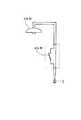
図7乃至図10は本発明の第3実施例を示すものである。第1実施例では、スイッチユニット5を壁スイッチ4と置き換えることで動作状態制御システムを構成したが、第3実施例では、照明機器(電気機器)29に通信制御部(通信制御手段)30(図8参照)を外付けすることでシステムを構成する。
【0041】
図7に示すように、照明機器29は、通常、家屋内の天井31に配置されている照明機器接続用のコンセント32に電源プラグ33を介して接続されるものである。第3実施例では、それらの間に遠隔操作用ユニット34を介挿するようになっている。遠隔操作用ユニット34は、外形が短円筒状をなすケース35を有しており、ケース35の上面側にはコンセント32に電気的接続を行うためのプラグ36を有し、下面側には照明機器29の電源プラグ33を受け入れるためのコンセント37を有している。
【0042】
図8は、遠隔操作用ユニット34を中心とする電気的構成を示すものである。プラグ36とコンセント37との間を接続する一方の電源線38aにはLED(内部で2つの素子が逆方向接続されているもの)39が介挿されており、他方の電源線38bには切り替えスイッチ(動作状態切替え手段)40及び電流モニタ(検出手段)41が介挿されている。切り替えスイッチ40の固定接点40aはコンセント37側に接続されており、可動接点40cはプラグ36側に接続され、固定接点40bはオープンである。尚、LED(電源投入状態報知手段)39は、図7に示すようにケース35の外部に露出している。
【0043】
また、ケース35の内部には、電源回路10,制御部11A及び無線送受信部12を備えており、これらが通信制御部30を構成している。制御部11Aの機能は第1実施例における制御部11と略同じであり、端末機器14より照明機器29のON/OFF指令が送信されると、それに応じて切替えスイッチ40を切替え制御し、可動接点40cを固定接点40a,40b側の何れかに切替えさせる。それに加えて、制御部11Aは、照明機器29をユーザが直接操作するためのつりひも(操作手段)42部分に配置されているつりひも駆動部(自動操作手段,動作状態切替え手段)43に制御信号を出力するようになっている。
【0044】
尚、照明機器29は、ユーザがつりひも42を引く毎に、
OFF(消灯)→全ON(点灯レベル強)→半ON(点灯レベル弱)→
豆球ON→OFF→・・・
のように動作状態が循環的に遷移するように構成されている。
【0045】
図9は、つりひも駆動部43の構成を示すものである。つりひも駆動部43は、照明機器1の笠44部分に固定される取付け板45に部品が搭載されている。シーソー機構46の支柱47は取付け板45に固定され、回動棒48の中点を回動自在に支持している。
【0046】
回動棒48の図9中左端側と取付け板45との間にはばね49が取り付けられており、回動棒48の右端側には磁石50が取付けられている。そして、磁石50の取付け位置に対応して、取付け板45には電磁石51が配置されている。電磁石51は、制御部11Aによって駆動制御される。また、回動棒48の左端側と支柱47の支点との間には、つりひも42の途中部分が巻き付けられて固定されている。
【0047】
即ち、回動棒48は、通常はばね49の付勢力により左端側が上方にひきつけられているが、電磁石51の図示しないコイルに通電が行なわれると、電磁石51は、ばね49の付勢力に抗して右端側の磁石50をひきつけるので、回動棒48は支点を中心として半時計方向に回動し、左端側のつりひも42は下方に引き下げられるように構成されている。また、ユーザは、つりひも42を自身の手で直接下方に引き下げることで、照明機器29を通常通りに操作することも可能である。
【0048】
次に、第3実施例の作用について図10をも参照して説明する。図10は、制御部11Aによる制御内容を示すフローチャートであり、第1実施例における図4に第3実施例独自の制御内容を追加したものである。制御部11Aは、ステップA3において「NO」と判断するとステップA7に移行し、端末機器14より送信された信号がOFF信号であるか否かを判定する。OFF信号であれば(「YES」)ステップA6に移行し、OFF信号でなければ(「NO」) ステップA8に移行して、端末機器14より送信された操作指令が全ON,半ON,豆球ON,の何れであるかを判定する。尚、ステップA5においては、切り替えスイッチ40の可動接点40cを切替える。
【0049】
次に、制御部11Aは、ステップA9に移行し、電流モニタ41の出力信号を参照して照明機器29の現在の動作状態が、全ON,半ON,豆球ON,OFFの何れであるかを判定する。そして、その状態と操作指令とに応じて、つりひも駆動部43の電磁石51に駆動信号を出力する(ステップA10)。
【0050】
例えば、照明機器29の現在の状態が「豆球ON」である場合に操作指令が「半ON」であれば、制御部11Aは電磁石51に3回通電を行う。すると、つりひも駆動部43によってつりひも42が3回引き下げられて、照明機器29は、豆球ON→OFF→全ON→半ON,のように動作状態が切替わる。また、現在の状態が「全ON」である場合に操作指令が「豆球ON」であれば、制御部11Aは電磁石51を2回だけ通電させる。すると、つりひも駆動部43によってつりひも42が2回引き下げられて、照明機器29は、全ON→半ON→豆球ON,のように動作状態が切替わる。
【0051】
以上のように第3実施例によれば、動作状態が全ONからOFFまで複数段階に遷移可能に構成される照明機器29のつりひも42部分につりひも駆動部43を配置し、端末機器14による遠隔操作によってつりひも42を操作可能としたので、つりひも42の直接操作とは独立に照明機器29の動作状態を切替えられるようにするため電気的構成を直接変更する必要がなくなるので、システムの構成をより容易に行うことができる。また、遠隔操作によって照明機器29の動作状態を段階的に遷移させることが簡単にできる。
【0052】
(第4実施例)
図11乃至図13は本発明の第4実施例を示すものであり、第3実施例と異なる部分についてのみ説明する。第4実施例では、照明機器(電気機器)53は、つりひも42による直接操作とは別に、例えば、赤外線を利用したリモコン(操作手段)54を用いて見通し内で遠隔操作することも可能となるように構成されている。即ち、具体的には図示しないが、リモコン54より送信される赤外線信号を受信して動作状態を切替えるための制御ユニットが照明機器53に内蔵されている。
【0053】
そして、照明機器53は、第3実施例の照明機器29と同様に、ユーザがつりひも42を引く毎に動作状態がOFF→全ON→半ON→豆球ON→OFF→・・・のように循環的に遷移すると共に、リモコン54より送信される赤外線信号によっても動作状態の切替が可能となるように構成されている。
【0054】
第4実施例では、つりひも駆動部43に代えてリモコン操作部(自動操作手段,動作状態切替え手段)55が配置されている。即ち、図11に示すように、リモコン54は、ユーザによって操作されない場合は、家屋内の壁面などに取り付けられているホルダ56に収納されているが、そのホルダ56にリモコン操作部55を配置する。尚、電気的構成を示す図12において、遠隔操作用ユニット34は第3実施例と同じ構成であり、制御部11Aは、つりひも駆動部43に代えてリモコン操作部55に駆動信号を出力するようになっている。
【0055】
図13は、リモコン操作部55の構成を示す断面図である。リモコン操作部55の操作子57は取付け板58によって支持されており、リモコン54の操作ボタン59の位置に合わせて配置されている。操作子57は磁石で構成されており、その外周部分にはコイル60が配置されていると共に、コイル60と操作子57の鍔部57aとの間にはばね61が配置されている。操作子57は、通常はばね61により図13中上方(反リモコン方向)に付勢されている。
【0056】
そして、この状態から、制御部11Aによりコイル60に通電が行われると、コイル60が発生する磁界と操作子57が帯びている磁界とが反発し、操作子57は、ばね61の付勢力に抗して下方に変位する。すると、操作子57は、リモコン54の操作ボタン59を押下する。
【0057】
尚、リモコン54は、操作ボタン59が押下される毎につりひも42が引き下げられた場合と同様に動作状態を切替えるものであっても良いし、また、各動作状態に直接切替えるための操作ボタン59を夫々備えていても良い(勿論、双方を同時に備えていても良い)。前者の場合、制御部11Aは第3実施例のフローチャートと同様にリモコン操作部55を駆動すれば良い。また、後者の場合は、リモコン操作部55の操作子57を夫々の操作ボタン59に対応して配置し、制御部11Aはリモコン54より送信された信号に応じて何れの操作子57を駆動するか決定すれば良い。
【0058】
以上のように第4実施例によれば、照明機器53のリモコン54が収納されるホルダ56にリモコン操作部55を配置し、端末機器14による遠隔操作によってリモコン54の操作ボタン59を操作可能とした。従って、第3実施例と同様の、つりひも42の直接操作とは独立に照明機器53の動作状態を切替えられるようにするため電気的構成を直接変更する必要がなくなり、システムの構成をより容易に行うことができ、遠隔操作により照明機器53の動作状態を段階的に遷移させることが簡単にできる。
【0059】
(第5実施例)
図14及び図15は本発明の第5実施例を示すものであり、第1実施例と異なる部分についてのみ説明する。第5実施例は、テーブルタップ62の内部に通信制御部等を配置した構成を示す。テーブルタップ62は、ケース63に電源コンセント64を例えば6個配置してなる6口構成であり、電源プラグ65を商用交流電源のコンセントに接続することにより、それら6個の電源コンセント64に接続される電気機器に交流電源を供給可能となっている。また、各電源コンセント64に対応して、夫々について電源ON/OFFの切替えを行なうためのシーソースイッチ66が配置されている。
【0060】
電気的構成を示す図15において、ケース63内部の電気的構成は、基本的に第1実施例と同様である。即ち、各電源コンセント64につき、シーソースイッチ66に対応する手動スイッチ部(操作手段)67Mと、遠隔制御スイッチ部(動作状態切替え手段)67Rとを備えると共に、LED(電源投入状態報知手段)68,電流モニタ(検出手段)69も配置されている。
【0061】
また、ケース63の内部には、第1実施例の通信制御部13と同様に、電源回路70,制御部71及び無線送受信部72よりなる通信制御部(通信制御手段)73が配置されており、LED68と無線送受信部72のアンテナ72aはケース63の外部に露出している。そして、制御部71は、端末機器14より送信される指令に応じて各電源コンセント64に対する電源供給を、シーソースイッチ66による操作とは独立に制御する。
【0062】
以上のように第5実施例によれば、テーブルタップ62の内部に、遠隔制御スイッチ部67Rと通信制御部73とを配置したので、各電源コンセント64に接続される電気機器は、ユーザがシーソースイッチ66を直接操作することで動作状態を切替えることができると共に、端末機器14を用いて遠隔操作することも可能となる。
【0063】
(第6実施例)
図16は本発明の第6実施例を示すものである。第6実施例の構成は基本的に第1実施例と同様であり、第6実施例は、通信制御部13の制御部11及び端末機器14の制御部17が行う付加的な処理内容を示す。図16(a)は、制御部11が実行する動作状態判定処理のフローチャートである。制御部11は、一定時間毎にこの処理を実行するようになっている。
【0064】
先ず、制御部11は、電流モニタ15の出力信号を参照し(ステップB1)、電流値が前回参照した値から変化しているか否かを判断する(ステップB2)。そして、前回参照した値から変化している場合は(「YES」)端末機器14に照明機器1の動作状態を送信し(ステップB3)、変化していない場合は(「NO」)そのままメインルーチンにリターンする。尚、この処理は、照明機器1A,1Bの夫々について行う。
【0065】
例えば、照明機器1の各動作状態に対応する消費電力と消費電流との関係は以下のようになる(但し、商用交流電源電圧が100Vの場合)。
【0066】
以上のように構成された第6実施例によれば、照明機器1に流れる電流を検出して通信制御部13に通知する電流モニタ15を備えて、通信制御部13は通知された電流の検出結果に基づく照明機器1の動作状態を端末機器14に送信し、端末機器14は、表示部20にその情報を表示してユーザに報知するので、ユーザは、照明機器1を見通せない位置から遠隔操作を行なう場合でも、照明機器1の動作状態を確認することができる。
【0067】
(第7実施例)
図17は本発明の第7実施例を示すものである。第7実施例の構成は基本的に第1実施例と同様であり、ソフトウエア的な処理が若干異なっている。端末機器14は、通信制御部13側に制御指令を送信する際に、当該指令を通信制御部13に実行させる時刻(所定条件)を指定可能となっている。
【0068】
そして、制御部11は、ステップA4,A6において夫々「NO」と判断すると、ONまたはOFF指令につき実行時刻が指定されているか否かを判断する(ステップA11)。実行時刻の指定がない場合(「NO」)、制御部11はステップA5に移行し、指定がある場合は(「YES」)内蔵されているリアルタイムクロック(図示せず)を参照してその指定時刻に達するまで待機し(ステップA12)、達した時点で(「YES」)ステップA5に移行する。
【0069】
以上のように構成された第7実施例によれば、通信制御部13の制御部11は、端末機器14より照明機器1の動作状態を切替えるための指令を受信すると、指定された時刻に達した時点でその指令を実行するので、例えば、ユーザが照明機器1を遠隔操作することを思い付いたが、実際に動作を開始させたい時点はそれよりも後の方が都合が良い場合などに有効である(即ち、動作を開始させる時刻に合わせて遠隔操作を行う必要がない)。
【0070】
また、例えば、防犯上の理由により無人である室内の照明機器を点灯させるような場合に、
21時:台所の照明:ON,居間の照明:OFF
24時:寝室の照明:ON,
26時:寝室の照明:OFF
といったように、ユーザの実際の生活パターンに一致するように照明を制御したり、定期的にトイレの照明をONさせるなどしてよりリアリティーのある制御が可能となる。従って、防犯効果が向上する。
【0071】
(第8実施例)
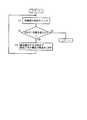
図18は本発明の第8実施例を示すものである。第8実施例の構成は基本的に第1実施例と同様であり、ソフトウエア的な処理が若干異なっている。通信制御部13の制御部11は、制御対象となる電気機器が複数ある場合に、それらの電力消費状態を電流モニタ15により電流消費状態としてモニタすることで、システム的に制御を行うようになっている。
【0072】
例えば、通信制御部13が、第1実施例よりも多数の照明機器1を同時に制御しているものとする。制御部11の制御内容を示す図18において、制御部11は、それらの照明機器1の電流値を電流モニタ15によりモニタすると(ステップC1)、その電流値の合計が予め定められている上限値を超えたか否かを判断する(ステップC2)。
【0073】
ここで、上限値は、例えば、電力会社と契約している消費電力量が30Aであるとすれば、それよりも低い値に設定しておく(例えば、25Aなど)。この時、通信制御部13の制御対象外であり、常時動作している例えば冷蔵庫などがある場合は、その消費電流量も考慮し適当なマージンを設定して定めれば良い。
【0074】
ステップC2において、電流値の合計が上限値以内であれば(「NO」)そのままメインルーチンにリターンし、合計が上限値を超えていれば(「YES」)、複数の照明機器1について予め設定されている優先順位がその時点で最も低いものの電源をOFFする(ステップC3)。それから、ステップC1に戻り、ステップC2における判定を繰り返す。
【0075】
ここで、優先順位は、高い方から例えば、
1:居間,2:台所,3:寝室,4:廊下,5:風呂,6:トイレ
のように予め設定しておき、優先順位が最低である「6:トイレ」の照明機器1からOFFする。それでも、電流値の合計が上限値を超えている場合は、その時点で優先順位が最低となっている「5:風呂」の照明機器1からOFFする。
【0076】
以上のように第8実施例によれば、電流モニタ15を複数の照明機器1に配置して夫々の電力消費状態を検出させ、通信制御部13の制御部11は、電流モニタ15より通知された夫々の消費電流量の合計が上限値を超える場合は、優先順位が低い照明機器1から順次その電源をOFFさせるようにした。従って、遠隔操作を行った場合に、契約電力量を超えて配電設備に設置されているブレーカが開離してしまい、そのブレーカを介して電源が供給されている電気機器の動作が全て停止してしまうような事態を回避することができる。
【0077】
(第9実施例)
図19は本発明の第9実施例を示すものであり、第3実施例と同一部分には同一符号を付して説明を省略し、以下異なる部分についてのみ説明する。第9実施例では、第3実施例におけるつりひも駆動部43に代えて、異なる構造のつりひも駆動部(自動操作手段,動作状態切替え手段)74を用いたものである。取付け板45には、ステッピングモータ75が搭載されている。モータ75の回転軸75aには穴が開けられており、照明機器29のつりひも42は、その穴に通されている。また、回転軸75aの若干下方に位置する部位のつりひも42には、穴径よりも外形寸法が大であるストッパ76が固定されている。
【0078】
次に、第9実施例の作用について説明する。制御部11Aからの駆動信号を受けてモータ75が何れかの方向に回転すると、つりひも42は、回転軸75aの穴に通されている箇所から下方に位置する部分が巻き取られて行く。すると、ストッパ76が回転軸75a方向に次第に移動する。そして、ストッパ76が回転軸75aの穴部分に当接すると、その時点からつりひも42の回転軸75aよりも上方に位置する部分が巻き取られ、つりひも42は下方に引き下げられる。
【0079】
制御部11Aは、駆動信号を所定パルス数だけ出力することで、つりひも42を所定量だけ下方に引き下げて照明機器29の動作状態を切替えさせると、その後、モータ75を反転させて回転軸75aに巻き取られたつりひも42を初期状態に戻すようにする。従って、ユーザは、第3実施例と同様に、つりひも42を自身の手で直接下方に引き下げることで照明機器29を通常通りに操作することも可能である。
【0080】
以上のように第9実施例によれば、照明機器29のつりひも42部分につりひも駆動部74を配置し、端末機器14による遠隔操作によってつりひも42を操作可能としたので、第3実施例と同様の効果を得ることができる。
【0081】
本発明は上記し且つ図面に記載した実施例にのみ限定されるものではなく、以下のような変形または拡張が可能である。
電気機器は、照明機器に限ることなく、その他、エアコン,扇風機,テレビ,ビデオデッキ,電子レンジなどでも良く、夫々の操作形態に合わせて動作状態切替え手段,或いは自動操作手段を配置すれば良い。
第1実施例において、必ずしも壁スイッチ4をスイッチユニット5に置き換える必要はなく、壁スイッチ4をそのまま残して壁スイッチ部6Mとして利用し、その他必要な構成要素を壁スイッチ4の内部に組み付けるようにしても良い。 第1実施例などにおいて、通信用のアンテナは、通信状態に問題がない場合はスイッチユニット5等の内部に配置しても良い。
【0082】
通信方式は無線信号を用いるものに限らず、例えば、商用交流電源線を利用して行う方式でも良く、要は、電気機器の見通し外からでも通信が可能な方式であれば良い。
検出手段は、電流モニタ15に限ることなく、その他電圧,照度や温度などをモニタするものでも良い。
端末機器14の表示部20に、当該端末機器14の操作ガイダンスを表示させても良い。
電気機器の動作用電源は商用交流電源に限ることなく、二次電池でも良い。 第2実施例において、通信制御部に携帯電話機としての機能、若しくは一般電話機としての機能を持たせて、家庭内通信網28を介すことなく通信を行うようにしても良い。
第3実施例において、電磁石51が発生する磁力の強さによっては、磁石50に代えて磁性体の金属を配置しても良い。
【0083】
第6実施例において、照明機器1の動作状態の送信は、制御部11において前回のモニタ値より変化しているか否かを判定することなく一定時間毎に行うようにしても良い。また、端末機器14側から動作状態の送信要求があった場合のみ電流値をモニタして送信するようにしても良い。
第7実施例において、所定条件は指令の実行時刻に限らず、例えば、指令を送信した時点から2時間後といったように時間を指定しても良い。この場合、制御対象機器がエアコンであれば、例えば帰宅時に部屋の温度が快適な温度となっているように動作させることができる。また、例えば、家屋の玄関ドアの開閉状態を検出するようにして、ドア開いたことをトリガとし手照明をONさせたりボイスレコーダに予め録音した音声を再生させるなどしても良い。斯様にして、恰も家人が在宅であるように見せかけるようにすれば、防犯上有効である。
第8実施例において、第3実施例の照明機器29のように、電源が投入された場合の動作状態が複数あるものを制御している場合は、必ずしも電源をOFFさせる必要はなく消費電流がより小さくなるように動作状態を切替えても良い。
【0084】
また、第8実施例において、電気機器の電力消費状態は、電気機器や検出手段の種類に応じて電流以外のもので検出・判定するようにしても良い。
更に、第8実施例において、その時点における各電気機器の動作状態によって優先順位をダイナミックに変更するようにしても良い。例えば、電子レンジが調理中であればその優先順位が高くなるように設定して調理が中断することを防止する。また、ビデオデッキが録画予約中となっている場合は優先順位を最高に設定する。
加えて、第8実施例において、電気機器の優先順位を、動作状態を切替えた時点が最近であるものを最低に設定し、その時点が過去に遡るものについて優先順位が順次高くなるように設定しても良い。即ち、電気機器の一般的な使用状態を鑑みれば、動作を開始させた時点が最近の機器の動作をより早く停止させても問題が発生する可能性は極めて低いので、優先順位を妥当に設定することができる。また、それらの電気機器を複数のユーザが同時に使用するため、電気機器自体の種類では優先順位を定め難い場合にも有効である。
【0085】
【発明の効果】
本発明の電気機器の動作状態制御システムによれば、通信制御手段を既存の電気機器とその動作用電源との間に配置し、動作状態切替え手段を電気機器側に配置する、という最低限の構成変更を行なうことで、利用者は、遠隔操作用端末を操作して動作状態切替え手段を制御し、その電気機器の動作状態を切替えることができる。従って、既存の電気機器を見通し外から遠隔操作して集中管理することが極めて容易に可能となる。そして、電気機器が予め備えている操作手段による動作状態の切替えもそのまま行なうことができ、電源が投入された場合の動作状態が複数段階に遷移可能に構成されている電機機器の動作状態を、遠隔操作によって段階的に遷移させることができる(請求項1)。
また、通信制御手段を、遠隔操作用端末より電気機器の動作状態を切替えるための指令を受信した時点から、所定の条件が成立した時点で前記指令を実行可能に構成すれば、利用者が電気機器を遠隔操作することを思い付いたが、実際に動作を開始させたい時点はそれよりも後の方が都合が良い場合などに有効である(請求項2)。
また、遠隔操作用端末に報知手段を備えることで、利用者は、遠隔操作用端末によって電気機器を見通せない位置から遠隔操作を行なっている場合でも、報知手段によって電機機器の動作状態を確認できる。更に、例えば利用者が遠隔操作によって多数の電気機器を同時に動作させようとする場合に、それらの電力消費状態の合計が上限値を超えると、通信制御手段によってその合計が上限値以内となるように制御すれば、契約電力量を超えてブレーカが開離してしまい、そのブレーカを介して電源が供給されている電気機器の動作が全て停止してしまうような事態を回避できる(請求項3)。
【図面の簡単な説明】
【図1】本発明を電気機器たる照明機器に適用した場合の第1実施例であり、動作状態制御システムの電気機器側の構成を示す図
【図2】スイッチユニットが壁に取り付けられた状態の外観構成を示す図
【図3】(a)は、端末機器の外観を示す平面図、(b)は、端末機器を中心とする電気的構成を示す機能ブロック図
【図4】スイッチユニット側の制御部による制御内容を示すフローチャート
【図5】動作状態制御システムを導入する前の状態を示す図1相当図
【図6】本発明の第2実施例を示す図3相当図
【図7】本発明の第3実施例であり、照明機器と、家屋内の天井に配置されている照明機器接続用のコンセントに遠隔操作用ユニットを介挿する状態を示す分解斜視図
【図8】遠隔操作用ユニットを中心とする電気的構成を示す図
【図9】つりひも駆動部の構成を示す図
【図10】通信制御部の制御部による制御内容を示すフローチャート
【図11】本発明の第4実施例を示す図7相当図
【図12】図8相当図
【図13】リモコン操作部の構成を示す断面図
【図14】本発明の第5実施例であり、テーブルタップの外観構成を示す斜視図
【図15】図1相当図
【図16】本発明の第6実施例であり、(a)は制御部が実行する動作状態判定処理のフローチャート、(b)は端末機器の表示部に、通信制御部の制御部より送信された照明機器の動作状態を表示させた状態を示す図
【図17】本発明の第7実施例を示す図4相当図
【図18】本発明の第8実施例を示す図4相当図
【図19】本発明の第9実施例を示す図9相当図
【符号の説明】
1は照明機器(電気機器)、4は壁スイッチ(操作手段)、6Mは壁スイッチ部(操作手段)、6Rは遠隔制御スイッチ部(動作状態切替え手段)、9はLED(電源投入状態報知手段)、13は通信制御部(通信制御手段)、14は端末機器(遠隔操作用端末)、15は電流モニタ(検出手段)、20は表示部(報知手段)、23は端末機器(遠隔操作用端末)、25は通信制御部(通信制御手段)、26は電話回線網(公衆通信回線)、29は照明機器(電気機器)、30は通信制御部(通信制御手段)、39はLED(電源投入状態報知手段)、40は切替えスイッチ(動作状態切替え手段)、41は電流モニタ(検出手段)、42はつりひも(操作手段)、43はつりひも駆動部(自動操作手段,動作状態切替え手段)、53は照明機器(電気機器)、54はリモコン(操作手段)、55はリモコン操作部(自動操作手段,動作状態切替え手段)、67Mは手動スイッチ部(操作手段)、67Rは遠隔制御スイッチ部(動作状態切替え手段)、68はLED(電源投入状態報知手段)、69は電流モニタ(検出手段)、73は通信制御部(通信制御手段)を示す。[0001]
BACKGROUND OF THE INVENTION
The present invention relates to an operation state control system for remotely operating an electrical device provided with an operation means for a user to operate and switch an operation state from outside the line of sight.
[0002]
[Prior art]
For example,
[0003]
[Patent Document 1]
JP 2000-59404 A
[0004]
[Patent Document 2]
JP-A-5-302749
[0005]
[Problems to be solved by the invention]
That is, in
[0006]
Moreover, in
[0007]
In each of these patent documents, a system for centrally managing each electrical device is configured by using an electrical device configured for the system. Therefore, if the user wishes to introduce the above-mentioned centralized management system, if there are electrical devices that are already installed and used in the home, etc., the system is configured by replacing them. It must be very uneconomical.
[0008]
The present invention has been made in view of the above circumstances, and an object of the present invention is to provide an operation state control system for an electric device that enables remote operation from outside the line of sight using the existing electric device as it is. .
[0009]
[Means for Solving the Problems]
In order to achieve the above object, an operation state control system for an electric device according to
The electrical equipment is configured such that the operating state when power is turned on can be transitioned to a plurality of stages,
The operation state switching means for operating and switching the operation state of the electric device independently of the operation in the operation unit is arranged on the electric device side,
The operation state switching means can be controlled via the communication control means when a user operates a remote operation terminal that performs non-line-of-sight communication with the communication control means.
[0010]
In other words, the user can remotely change the configuration by arranging the communication control means between the existing electric equipment and the power supply for operation and arranging the operation state switching means on the electric equipment side. It is possible to operate the operation terminal and control the operation state switching means to switch the operation state of the electric device. Therefore, it becomes extremely easy to perform centralized management by remotely operating an existing electrical device from outside the line of sight. And since the switching of the operation state by the operating means provided in advance in the electric device can be performed as it is, the convenience is not lowered.
[0011]
In the above, “operating means” of an electric device is an operating means provided in advance on an off-the-shelf electric device, and includes, for example, an electric device that is remotely operated within a line-of-sight using an infrared remote controller. And In addition, the “electric device side” where the operation state switching means is arranged means “the electric device side” in the relative positional relationship with the remote operation terminal for performing remote operation.
And since the system of this invention is introduce | transduced into the electric equipment comprised so that the operation state when a power supply is turned on can be changed in multiple steps, the operation state can be changed in steps by remote operation.
[0012]
The operation state control system for an electric device according to
The operation state switching means for operating and switching the operation state of the electric device independently of the operation in the operation unit is arranged on the electric device side,
The operation state switching means can be controlled via the communication control means when a user operates a remote operation terminal that performs non-line-of-sight communication with the communication control means,
The communication control means is configured to be capable of executing the command when a predetermined condition is satisfied from the time when the command for switching the operation state of the electrical device is received from the remote operation terminal. And
That is, the user can remotely change the configuration by arranging the communication control means between the existing electric device and the power supply for operation and arranging the operation state switching means on the electric device side. It is possible to control the operation state switching means by operating the operation terminal and switch the operation state of the electric device. Therefore, it becomes extremely easy to remotely control existing electrical devices from outside the line of sight and centrally manage them. And since the switching of the operation state by the operating means provided in advance in the electric device can be performed as it is, the convenience is not lowered.
Further, since the communication control means is configured to be able to execute the command when a predetermined condition is satisfied from the time when the command for switching the operation state of the electrical device is received from the remote operation terminal, for example, the user Came up with remote control of electrical equipment, but it is effective when it is more convenient to start the operation later.
[0013]
The operation state control system for an electric device according to
The operation state switching means for operating and switching the operation state of the electric device independently of the operation in the operation unit is arranged on the electric device side,
The operation state switching means can be controlled via the communication control means when a user operates a remote operation terminal that performs non-line-of-sight communication with the communication control means,
Detecting means for detecting an operating state of the electrical equipment and notifying the communication control means;
The communication control means transmits the detection result notified from the detection means to the remote operation terminal,
The remote operation terminal includes an informing means for informing the transmitted detection result,
The detection means is arranged in a plurality of electric devices to detect each power consumption state,
The communication control unit is configured to be able to control the operation states of the plurality of electric devices, and when the total of the power consumption states notified from the detection unit exceeds the upper limit value, the priority order is low. The power consumption is sequentially reduced from an electric device or the operation is stopped, and the total is controlled to be within the upper limit value.
That is, the user can remotely change the configuration by arranging the communication control means between the existing electric device and the power supply for operation and arranging the operation state switching means on the electric device side. It is possible to control the operation state switching means by operating the operation terminal and switch the operation state of the electric device. Therefore, it becomes extremely easy to remotely control existing electrical devices from outside the line of sight and centrally manage them. And since the switching of the operation state by the operating means provided in advance in the electric device can be performed as it is, the convenience is not lowered.
In addition, since the remote operation terminal is provided with notification means for notifying the transmitted detection result, even when the user is performing remote operation from a position where the electric device cannot be seen by the remote operation terminal, the notification is performed. The operation state of the electrical equipment can be confirmed by the means.
Furthermore, for example, if the upper limit value is set to be slightly lower than the contracted power amount with the electric power company, when the user tries to operate a large number of electric devices simultaneously by remote control, When the sum exceeds the upper limit value, the communication control means controls the sum to be within the upper limit value. Therefore, it is possible to avoid a situation in which the breaker is disconnected exceeding the contracted power amount and the operation of the electrical equipment to which power is supplied via the breaker is stopped.
[0014]
in this case,As described in
[0015]
Further, as described in
[0016]
Moreover, as described in claim 6,A power-on state notifying unit for notifying whether or not the electric device is powered on may be provided on the electric device side. With this configuration, even when the user does not directly operate and the operation state is switched by remote operation and the power is turned on or off, the user confirms the state by the power-on state notifying unit. be able to.
[0017]
Moreover, as described in claim 7,The communication control means and the remote operation terminal may be configured to be able to communicate via a public communication line. With this configuration, for example, even when the user is out, the operation state of the electric device can be remotely operated by a remote operation terminal via a telephone line or the like.
[0021]
DETAILED DESCRIPTION OF THE INVENTION
(First embodiment)
Hereinafter, a first embodiment when the present invention is applied to an illumination device as an electric device will be described with reference to FIGS. In FIG. 1 showing the configuration on the electric equipment side of the operation state control system, the lighting equipment 1 (A, B) is usually composed of a
[0022]
The
[0023]
The
[0024]
The
[0025]
FIG. 2 shows an external configuration of the
[0026]
FIG. 3A is a plan view showing an external appearance of the
[0027]
The
[0028]
In addition, about the communication performed between the
[0029]
Next, the operation of this embodiment will be described with reference to FIG. FIG. 4 is a flowchart showing the contents of control by the
[0030]
Next, the
The movable contact 6Rc of the remote
[0031]
For example, if the movable contact 6Mc of the wall switch unit 6M is on the fixed contact 6Ma side at this time, the movable contact 6Rc of the remote
[0032]
In step A4, if the current state of the
[0033]
On the other hand, if the transmitted signal is not an ON signal in step A3 ("NO"), the
[0034]
As described above, according to the present embodiment, the
[0035]
That is, by performing the minimum configuration change, the user can control the remote
[0036]
Further, according to the present embodiment, since the
[0037]
(Second embodiment)
FIG. 6 shows a second embodiment of the present invention. The same parts as those of the first embodiment are denoted by the same reference numerals and the description thereof is omitted. Only different parts will be described below. In the second embodiment, the terminal device (remote operation terminal) 23 side and the communication control unit (communication control means) 25 of the switch unit 24 where the
[0038]
That is, the wireless transmission /
[0039]
According to the second embodiment configured as described above, the communication control unit 25 and the
[0040]
(Third embodiment)
7 to 10 show a third embodiment of the present invention. In the first embodiment, the operation state control system is configured by replacing the
[0041]
As shown in FIG. 7, the
[0042]
FIG. 8 shows an electrical configuration centered on the
[0043]
The
[0044]
The
OFF (dark) → all ON (lighting level high) → half ON (lighting level weak) →
Bean ball ON → OFF → ・ ・ ・
Thus, the operation state is configured to transition cyclically.
[0045]
FIG. 9 shows the configuration of the
[0046]
A
[0047]
That is, the rotating
[0048]
Next, the operation of the third embodiment will be described with reference to FIG. FIG. 10 is a flowchart showing the contents of control by the
[0049]
Next, the
[0050]
For example, when the current state of the
[0051]
As described above, according to the third embodiment, the
[0052]
(Fourth embodiment)
11 to 13 show a fourth embodiment of the present invention, and only the parts different from the third embodiment will be described. In the fourth embodiment, the lighting device (electrical device) 53 can be remotely operated within the line of sight using, for example, a remote control (operation means) 54 using infrared rays, in addition to the direct operation by the
[0053]
Then, the lighting device 53, like the
[0054]
In the fourth embodiment, a remote control operation unit (automatic operation means, operation state switching means) 55 is disposed in place of the
[0055]
FIG. 13 is a cross-sectional view showing the configuration of the remote
[0056]
In this state, when the
[0057]
The
[0058]
As described above, according to the fourth embodiment, the remote
[0059]
(5th Example)
14 and 15 show a fifth embodiment of the present invention, and only the parts different from the first embodiment will be described. 5th Example shows the structure which has arrange | positioned the communication control part etc. inside the
[0060]
In FIG. 15 showing the electrical configuration, the electrical configuration inside the
[0061]
In addition, a communication control unit (communication control means) 73 including a
[0062]
As described above, according to the fifth embodiment, since the remote
[0063]
(Sixth embodiment)
FIG. 16 shows a sixth embodiment of the present invention. The configuration of the sixth embodiment is basically the same as that of the first embodiment, and the sixth embodiment shows the details of additional processing performed by the
[0064]
First, the
[0065]
For example, the relationship between power consumption and current consumption corresponding to each operation state of the
[0066]
According to the sixth embodiment configured as described above, the
[0067]
(Seventh embodiment)
FIG. 17 shows a seventh embodiment of the present invention. The configuration of the seventh embodiment is basically the same as that of the first embodiment, and the software processing is slightly different. When the
[0068]
When the
[0069]
According to the seventh embodiment configured as described above, when the
[0070]
In addition, for example, when lighting an indoor lighting device that is unattended for crime prevention reasons,
21:00: Kitchen lighting: ON, living room lighting: OFF
24:00: Bedroom lighting: ON,
26:00: Bedroom lighting: OFF
As described above, more realistic control is possible by controlling the lighting so as to match the actual life pattern of the user or periodically turning on the lighting of the toilet. Accordingly, the crime prevention effect is improved.
[0071]
(Eighth embodiment)
FIG. 18 shows an eighth embodiment of the present invention. The configuration of the eighth embodiment is basically the same as that of the first embodiment, and the software processing is slightly different. When there are a plurality of electrical devices to be controlled, the
[0072]
For example, it is assumed that the
[0073]
Here, for example, if the power consumption contracted with the electric power company is 30 A, the upper limit value is set to a lower value (for example, 25 A). At this time, if there is, for example, a refrigerator that is not controlled by the
[0074]
In step C2, if the sum of the current values is within the upper limit value (“NO”), the process directly returns to the main routine, and if the sum exceeds the upper limit value (“YES”), the plurality of
[0075]
Here, the priority order is, for example, from the highest order:
1: living room, 2: kitchen, 3: bedroom, 4: corridor, 5: bath, 6: toilet
The
[0076]
As described above, according to the eighth embodiment, the
[0077]
(Ninth embodiment)
FIG. 19 shows a ninth embodiment of the present invention. The same parts as those of the third embodiment are designated by the same reference numerals and the description thereof is omitted. Only the different parts will be described below. In the ninth embodiment, instead of the
[0078]
Next, the operation of the ninth embodiment will be described. When the
[0079]
When the
[0080]
As described above, according to the ninth embodiment, the strap driving section 74 is disposed in the
[0081]
The present invention is not limited to the embodiments described above and shown in the drawings, and the following modifications or expansions are possible.
The electric device is not limited to the lighting device, but may be an air conditioner, a fan, a television, a video deck, a microwave oven, or the like, and an operation state switching unit or an automatic operation unit may be arranged in accordance with each operation mode.
In the first embodiment, it is not always necessary to replace the
[0082]
The communication method is not limited to a method using a radio signal, and may be a method that uses a commercial AC power line, for example, and may be any method that enables communication from outside the line-of-sight of an electric device.
The detection means is not limited to the
The operation guidance of the
The power supply for operation of the electric device is not limited to a commercial AC power supply, and may be a secondary battery. In the second embodiment, the communication control unit may have a function as a mobile phone or a function as a general telephone so that communication can be performed without going through the home communication network 28.
In the third embodiment, depending on the strength of the magnetic force generated by the
[0083]
In the sixth embodiment, the operation state of the
In the seventh embodiment, the predetermined condition is not limited to the execution time of the command. For example, the predetermined time may be specified as two hours after the command is transmitted. In this case, if the control target device is an air conditioner, for example, it can be operated so that the room temperature is a comfortable temperature when returning home. Further, for example, the open / closed state of the front door of the house may be detected, and when the door is opened, hand lighting may be turned on, or voice recorded in advance by a voice recorder may be reproduced. In this way, it is effective for crime prevention if the householder is made to appear to be at home.
In the eighth embodiment, when controlling a device having a plurality of operating states when the power is turned on, such as the
[0084]
In the eighth embodiment, the power consumption state of the electric device may be detected / determined by something other than the current according to the type of the electric device or the detection means.
Furthermore, in the eighth embodiment, the priority order may be dynamically changed according to the operating state of each electrical device at that time. For example, if the microwave oven is being cooked, the priority is set to be higher to prevent cooking from being interrupted. If the video deck is in recording reservation, the highest priority is set.
In addition, in the eighth embodiment, the priority order of the electric equipment is set to the lowest one when the operation state is switched to the latest, and the priority order is set so that the priority order is sequentially increased for those that go back to the past. You may do it. In other words, considering the general usage state of electrical equipment, it is very unlikely that a problem will occur even if the operation of the latest equipment stops earlier, so the priority should be set appropriately. can do. In addition, since a plurality of users use these electric devices at the same time, it is also effective when it is difficult to determine the priority order according to the type of the electric device itself.
[0085]
【The invention's effect】
According to the electrical equipment operation state control system of the present invention, the communication control means is disposed between the existing electrical equipment and the power supply for operation, and the operation state switching means is disposed on the electrical equipment side. By changing the configuration, the user can operate the remote operation terminal to control the operation state switching means and switch the operation state of the electric device. Therefore, it becomes extremely easy to perform centralized management by remotely operating an existing electrical device from outside the line of sight. And the switching of the operation state by the operating means provided in advance in the electric equipment can be performed as it is.The operation state of the electrical equipment that is configured so that the operation state when the power is turned on can be changed in a plurality of stages can be changed stepwise by remote operation.
In addition, if the communication control unit is configured to be able to execute the command when a predetermined condition is satisfied from the time when the command for switching the operation state of the electrical device is received from the remote operation terminal, the user can It has been conceived that the device is remotely controlled, but it is effective when it is more convenient to start the operation later than that.
In addition, by providing the remote operation terminal with the notification means, the user can check the operating state of the electrical equipment by the notification means even when the remote operation terminal performs remote operation from a position where the electrical device cannot be seen. . Further, for example, when a user tries to operate a large number of electrical devices simultaneously by remote operation, if the total of their power consumption state exceeds the upper limit value, the total is within the upper limit value by the communication control means. If the control is performed, it is possible to avoid a situation in which the breaker is separated beyond the contracted electric energy and the operation of the electrical equipment to which power is supplied via the breaker is completely stopped (Claim 3). .
[Brief description of the drawings]
FIG. 1 is a diagram showing a configuration of an operation state control system on an electric device side according to a first embodiment when the present invention is applied to a lighting device as an electric device.
FIG. 2 is a diagram showing an external configuration in a state where a switch unit is attached to a wall.
3A is a plan view showing an external appearance of a terminal device, and FIG. 3B is a functional block diagram showing an electrical configuration centering on the terminal device.
FIG. 4 is a flowchart showing the contents of control by the control unit on the switch unit side.
FIG. 5 is a view corresponding to FIG. 1 showing a state before the operation state control system is introduced.
6 is a view corresponding to FIG. 3, showing a second embodiment of the present invention.
FIG. 7 is an exploded perspective view showing a state in which the remote control unit is inserted into the lighting device and an outlet for connecting the lighting device arranged on the ceiling in the house, according to the third embodiment of the present invention.
FIG. 8 is a diagram showing an electrical configuration centered on a remote control unit;
FIG. 9 is a diagram showing a configuration of a strap driver
FIG. 10 is a flowchart showing the contents of control by the control unit of the communication control unit.
FIG. 11 is a view corresponding to FIG. 7 showing a fourth embodiment of the present invention.
FIG. 12 is equivalent to FIG.
FIG. 13 is a cross-sectional view showing the configuration of a remote control operation unit
FIG. 14 is a perspective view showing an external configuration of a table tap according to a fifth embodiment of the present invention.
15 is equivalent to FIG.
FIG. 16 is a sixth embodiment of the present invention, wherein (a) is a flowchart of an operation state determination process executed by the control unit, and (b) is transmitted from the control unit of the communication control unit to the display unit of the terminal device. Showing the state of displaying the operating state of the lighting equipment
FIG. 17 is a view corresponding to FIG. 4 showing a seventh embodiment of the present invention.
18 is a view corresponding to FIG. 4 showing an eighth embodiment of the present invention.
FIG. 19 is a view corresponding to FIG. 9 showing a ninth embodiment of the present invention.
[Explanation of symbols]
1 is a lighting device (electrical device), 4 is a wall switch (operation means), 6M is a wall switch section (operation means), 6R is a remote control switch section (operation state switching means), and 9 is an LED (power-on state notification means). ), 13 is a communication control unit (communication control unit), 14 is a terminal device (remote operation terminal), 15 is a current monitor (detection unit), 20 is a display unit (notification unit), and 23 is a terminal device (for remote operation). Terminal), 25 a communication control unit (communication control means), 26 a telephone network (public communication line), 29 lighting equipment (electrical equipment), 30 a communication control unit (communication control means), and 39 an LED (power supply) (Insertion state notifying means), 40 is a changeover switch (operation state switching means), 41 is a current monitor (detection means), 42 is a strap (operation means), 43 is a strap drive unit (automatic operation means, operation state switching means), 53 is lighting Device (electrical equipment), 54 is a remote control (operation means), 55 is a remote control operation section (automatic operation means, operation state switching means), 67M is a manual switch section (operation means), 67R is a remote control switch section (operation state switching) Means), 68 is an LED (power-on state notifying means), 69 is a current monitor (detecting means), and 73 is a communication control unit (communication control means).
Claims (7)
Translated fromJapanese前記電機機器は、電源が投入された場合の動作状態が複数段階に遷移可能に構成され、
前記電気機器の動作状態を、前記操作手段における操作とは独立に操作して切替えるための動作状態切替え手段を前記電気機器側に配置し、
前記動作状態切替え手段を、前記通信制御手段と見通し外通信を行う遠隔操作用端末を利用者が操作することで、前記通信制御手段を介して制御可能とすることを特徴とする電気機器の動作状態制御システム。A communication control means is arranged between an electric device operated by an operation means for a user to operate and switch an operation state, and an operation power source of the electric device,
The electrical equipment is configured such that the operating state when power is turned on can be transitioned to a plurality of stages,
The operation state switching means for operating and switching the operation state of the electric device independently of the operation in the operation unit is arranged on the electric device side,
The operation of the electric equipment, characterized in that the operation state switching means can be controlled via the communication control means when a user operates a remote operation terminal that performs non-line-of-sight communication with the communication control means. State control system.
前記電気機器の動作状態を、前記操作手段における操作とは独立に操作して切替えるための動作状態切替え手段を前記電気機器側に配置し、
前記動作状態切替え手段を、前記通信制御手段と見通し外通信を行う遠隔操作用端末を利用者が操作することで、前記通信制御手段を介して制御可能とし、
前記通信制御手段は、前記遠隔操作用端末より前記電気機器の動作状態を切替えるための指令を受信した時点から、所定の条件が成立した時点で前記指令を実行可能に構成されていることを特徴とする電気機器の動作状態制御システム。A communication control means is arranged between an electric device operated by an operation means for a user to operate and switch an operation state, and an operation power source of the electric device,
The operation state switching means for operating and switching the operation state of the electric device independently of the operation in the operation unit is arranged on the electric device side,
The operation state switching means can be controlled via the communication control means when a user operates a remote operation terminal that performs non-line-of-sight communication with the communication control means,
The communication control means is configured to be capable of executing the command when a predetermined condition is satisfied from the time when the command for switching the operation state of the electrical device is received from the remote operation terminal. An operating state control systemfor electrical equipment.
前記電気機器の動作状態を、前記操作手段における操作とは独立に操作して切替えるための動作状態切替え手段を前記電気機器側に配置し、
前記動作状態切替え手段を、前記通信制御手段と見通し外通信を行う遠隔操作用端末を利用者が操作することで、前記通信制御手段を介して制御可能とし、
前記電機機器の動作状態を検出して前記通信制御手段に通知する検出手段を備え、
前記通信制御手段は、前記検出手段より通知された検出結果を前記遠隔操作用端末に送信し、
前記遠隔操作用端末は、送信された検出結果を報知するための報知手段を備え、
前記検出手段は、複数の電気機器に配置されて夫々の電力消費状態を検出し、
前記通信制御手段は、前記複数の電気機器の動作状態を制御可能に構成されていると共に、前記検出手段より通知された夫々の電力消費状態の合計が上限値を超える場合は、優先順位が低い電気機器から順次その消費電力を低減させるか若しくはその動作を停止させて、前記合計が上限値以内となるように制御することを特徴とする電気機器の動作状態制御システム。A communication control means is arranged between an electric device operated by an operation means for a user to operate and switch an operation state, and an operation power source of the electric device,
The operation state switching means for operating and switching the operation state of the electric device independently of the operation in the operation unit is arranged on the electric device side,
The operation state switching means can be controlled via the communication control means when a user operates a remote operation terminal that performs non-line-of-sight communication with the communication control means,
Detecting means for detecting an operating state of the electrical equipment and notifying the communication control means;
The communication control means transmits the detection result notified from the detection means to the remote operation terminal,
The remote operation terminal includes an informing means for informing the transmitted detection result,
The detection means is arranged in a plurality of electric devices to detect each power consumption state,
The communication control unit is configured to be able to control the operation states of the plurality of electric devices, and when the total of the power consumption states notified from the detection unit exceeds the upper limit value, the priority order is low. An operation state control system foran electric device, wherein power consumption is sequentially reduced from the electric device or the operation is stopped, and the total is controlled to be within an upper limit value .
Priority Applications (6)
| Application Number | Priority Date | Filing Date | Title |
|---|---|---|---|
| JP2002309616AJP4363835B2 (en) | 2002-10-24 | 2002-10-24 | Electrical equipment operating state control system |
| KR1020057006892AKR100673122B1 (en) | 2002-10-24 | 2003-10-24 | Control system of operation state of electric equipment |
| CNB2003801020943ACN100534219C (en) | 2002-10-24 | 2003-10-24 | Operating state control system for electrical equipment |
| US10/532,339US20060221522A1 (en) | 2002-10-24 | 2003-10-24 | Electric device operation state control system |
| EP03758909AEP1558054A1 (en) | 2002-10-24 | 2003-10-24 | Electric device operation state control system |
| PCT/JP2003/013673WO2004039118A1 (en) | 2002-10-24 | 2003-10-24 | Electric device operation state control system |
Applications Claiming Priority (1)
| Application Number | Priority Date | Filing Date | Title |
|---|---|---|---|
| JP2002309616AJP4363835B2 (en) | 2002-10-24 | 2002-10-24 | Electrical equipment operating state control system |
Publications (2)
| Publication Number | Publication Date |
|---|---|
| JP2004147065A JP2004147065A (en) | 2004-05-20 |
| JP4363835B2true JP4363835B2 (en) | 2009-11-11 |
Family
ID=32171012
Family Applications (1)
| Application Number | Title | Priority Date | Filing Date |
|---|---|---|---|
| JP2002309616AExpired - Fee RelatedJP4363835B2 (en) | 2002-10-24 | 2002-10-24 | Electrical equipment operating state control system |
Country Status (6)
| Country | Link |
|---|---|
| US (1) | US20060221522A1 (en) |
| EP (1) | EP1558054A1 (en) |
| JP (1) | JP4363835B2 (en) |
| KR (1) | KR100673122B1 (en) |
| CN (1) | CN100534219C (en) |
| WO (1) | WO2004039118A1 (en) |
Families Citing this family (15)
| Publication number | Priority date | Publication date | Assignee | Title |
|---|---|---|---|---|
| ITMI20042217A1 (en) | 2004-11-18 | 2005-02-18 | Bticino Spa | RADIO CONTROLLED DEVIATOR FOR ELECTRICAL SYSTEMS |
| JP2006211470A (en)* | 2005-01-31 | 2006-08-10 | Mitsubishi Electric Corp | Wireless communication apparatus, wall switch, and wireless communication system |
| JP2008228427A (en)* | 2007-03-12 | 2008-09-25 | Kawamura Electric Inc | Switching system |
| FR2916111A1 (en) | 2007-05-10 | 2008-11-14 | Parrot Sa | AUTOMATICALLY CONTROLLED LIGHTING DEVICE AND INSTALLATION COMPRISING A PLURALITY OF THESE DEVICES |
| US20090058193A1 (en)* | 2007-08-31 | 2009-03-05 | Square D Company | Wall switch for lighting load management system for lighting systems having multiple power circuits |
| KR101536750B1 (en) | 2007-11-08 | 2015-07-15 | 삼성전자주식회사 | A remote control device for setting a mode according to the state of a broadcast receiving apparatus |
| CN102445990A (en)* | 2010-10-12 | 2012-05-09 | 鸿富锦精密工业(深圳)有限公司 | Keyboard with a keyboard body |
| JP2012090070A (en)* | 2010-10-20 | 2012-05-10 | Hibiya Eng Ltd | Remote switching apparatus, and remote operation system for electrical facilities |
| US9627928B2 (en)* | 2012-03-02 | 2017-04-18 | Ideal Industries, Inc. | Electrical outlet having wireless control capabilities |
| AU2013204369B2 (en)* | 2012-04-20 | 2015-09-03 | Smartswitch Pty Ltd | A programmable electrical control device |
| JP6094227B2 (en)* | 2013-01-10 | 2017-03-15 | 株式会社リコー | Feeding tap |
| JP5667257B1 (en)* | 2013-08-07 | 2015-02-12 | 三菱電機株式会社 | Home device, home system, control method, and program |
| JP6029607B2 (en)* | 2014-03-20 | 2016-11-24 | 三菱電機株式会社 | Wireless control system, switch device, wireless communication device, and arrangement state determination method of wireless communication device |
| CN105223815B (en)* | 2015-07-22 | 2017-10-31 | 广东天诚智能科技有限公司 | Intelligent household wireless control system |
| GB2579460B (en)* | 2017-08-29 | 2022-07-06 | Mitsubishi Electric Corp | Operation apparatus |
Family Cites Families (8)
| Publication number | Priority date | Publication date | Assignee | Title |
|---|---|---|---|---|
| JPH0295135A (en)* | 1988-09-29 | 1990-04-05 | Mitsubishi Electric Corp | load control device |
| JPH0591000A (en)* | 1991-09-26 | 1993-04-09 | Tamura Seisakusho Co Ltd | Device for power supply terminal |
| CN2250605Y (en)* | 1994-12-19 | 1997-03-26 | 杜光东 | Telephone capable of controlling electric appliance |
| US6080971A (en)* | 1997-05-22 | 2000-06-27 | David Seitz | Fluid heater with improved heating elements controller |
| JPH11220782A (en)* | 1998-01-30 | 1999-08-10 | Sanyo Electric Co Ltd | Appliance equipment unit centralized management system and equipment unit appliance power controller used for the same |
| TW421927B (en)* | 1998-01-30 | 2001-02-11 | Sanyo Electric Co | Central system for managing machines, central managing device for use in such system or terminals for use in the machines to be managed |
| US6218787B1 (en)* | 1998-04-20 | 2001-04-17 | Jrs Technology Inc. | Remote dimming control system for a fluorescent ballast utilizing existing building wiring |
| US6861956B2 (en)* | 2001-07-10 | 2005-03-01 | Yingco Electronic Inc. | Remotely controllable wireless energy control unit |
- 2002
- 2002-10-24JPJP2002309616Apatent/JP4363835B2/ennot_activeExpired - Fee Related
- 2003
- 2003-10-24USUS10/532,339patent/US20060221522A1/ennot_activeAbandoned
- 2003-10-24CNCNB2003801020943Apatent/CN100534219C/ennot_activeExpired - Fee Related
- 2003-10-24EPEP03758909Apatent/EP1558054A1/ennot_activeWithdrawn
- 2003-10-24KRKR1020057006892Apatent/KR100673122B1/ennot_activeExpired - Fee Related
- 2003-10-24WOPCT/JP2003/013673patent/WO2004039118A1/enactiveApplication Filing
Also Published As
| Publication number | Publication date |
|---|---|
| JP2004147065A (en) | 2004-05-20 |
| CN1709008A (en) | 2005-12-14 |
| KR100673122B1 (en) | 2007-01-22 |
| CN100534219C (en) | 2009-08-26 |
| US20060221522A1 (en) | 2006-10-05 |
| KR20050051714A (en) | 2005-06-01 |
| WO2004039118A1 (en) | 2004-05-06 |
| EP1558054A1 (en) | 2005-07-27 |
Similar Documents
| Publication | Publication Date | Title |
|---|---|---|
| JP4363835B2 (en) | Electrical equipment operating state control system | |
| US6713975B2 (en) | Lighting apparatus, lighting control system and home electric appliance | |
| US7415310B2 (en) | System for home automation | |
| US20210048910A1 (en) | Modular touch panel smart switches and systems | |
| JP5096563B2 (en) | Power supply | |
| CA3050384A1 (en) | Easy-install home automation light switch | |
| WO2012070439A1 (en) | Load-control switch and load-control switch system | |
| CA3104907C (en) | Retrofit smart home controller device with power supply module, charger and dock | |
| CN108702834A (en) | wireless switch | |
| JP2007189392A (en) | Residential equipment control system | |
| WO2015138219A1 (en) | Intui-network | |
| EA004946B1 (en) | Switch unit | |
| JP3551774B2 (en) | Power saving system | |
| KR100990131B1 (en) | System for controlling standby power | |
| CN205319048U (en) | Take intelligence of pivot easily to paste switch | |
| JP2002142269A (en) | Wireless switch system | |
| KR20020085620A (en) | Switch capable of being remote controlled | |
| JP2006073220A (en) | Switch remote controller | |
| CN115763129A (en) | Intelligent home controller | |
| JP5581185B2 (en) | Load control switch and load control switch system | |
| US20050025637A1 (en) | Direction control device for a ceiling fan | |
| CN204145836U (en) | Intelligent light sensing ceiling light and controller thereof | |
| TWI809482B (en) | Wiring apparatus, wiring system, and storage medium | |
| JP2004336896A (en) | Power feed unit | |
| TWM569958U (en) | Remote control device for power source |
Legal Events
| Date | Code | Title | Description |
|---|---|---|---|
| A621 | Written request for application examination | Free format text:JAPANESE INTERMEDIATE CODE: A621 Effective date:20050413 | |
| A131 | Notification of reasons for refusal | Free format text:JAPANESE INTERMEDIATE CODE: A131 Effective date:20080819 | |
| A521 | Request for written amendment filed | Free format text:JAPANESE INTERMEDIATE CODE: A523 Effective date:20080930 | |
| TRDD | Decision of grant or rejection written | ||
| A01 | Written decision to grant a patent or to grant a registration (utility model) | Free format text:JAPANESE INTERMEDIATE CODE: A01 Effective date:20090728 | |
| A01 | Written decision to grant a patent or to grant a registration (utility model) | Free format text:JAPANESE INTERMEDIATE CODE: A01 | |
| A61 | First payment of annual fees (during grant procedure) | Free format text:JAPANESE INTERMEDIATE CODE: A61 Effective date:20090818 | |
| FPAY | Renewal fee payment (event date is renewal date of database) | Free format text:PAYMENT UNTIL: 20120828 Year of fee payment:3 | |
| R151 | Written notification of patent or utility model registration | Ref document number:4363835 Country of ref document:JP Free format text:JAPANESE INTERMEDIATE CODE: R151 | |
| FPAY | Renewal fee payment (event date is renewal date of database) | Free format text:PAYMENT UNTIL: 20130828 Year of fee payment:4 | |
| S111 | Request for change of ownership or part of ownership | Free format text:JAPANESE INTERMEDIATE CODE: R313111 | |
| S111 | Request for change of ownership or part of ownership | Free format text:JAPANESE INTERMEDIATE CODE: R313114 | |
| S111 | Request for change of ownership or part of ownership | Free format text:JAPANESE INTERMEDIATE CODE: R313117 | |
| S111 | Request for change of ownership or part of ownership | Free format text:JAPANESE INTERMEDIATE CODE: R313113 | |
| R350 | Written notification of registration of transfer | Free format text:JAPANESE INTERMEDIATE CODE: R350 | |
| R350 | Written notification of registration of transfer | Free format text:JAPANESE INTERMEDIATE CODE: R350 | |
| R350 | Written notification of registration of transfer | Free format text:JAPANESE INTERMEDIATE CODE: R350 | |
| R350 | Written notification of registration of transfer | Free format text:JAPANESE INTERMEDIATE CODE: R350 | |
| S111 | Request for change of ownership or part of ownership | Free format text:JAPANESE INTERMEDIATE CODE: R313113 | |
| R350 | Written notification of registration of transfer | Free format text:JAPANESE INTERMEDIATE CODE: R350 | |
| LAPS | Cancellation because of no payment of annual fees |