JP4359860B2 - Distributed serial control system - Google Patents
Distributed serial control systemDownload PDFInfo
- Publication number
- JP4359860B2 JP4359860B2JP51917398AJP51917398AJP4359860B2JP 4359860 B2JP4359860 B2JP 4359860B2JP 51917398 AJP51917398 AJP 51917398AJP 51917398 AJP51917398 AJP 51917398AJP 4359860 B2JP4359860 B2JP 4359860B2
- Authority
- JP
- Japan
- Prior art keywords
- psic
- signal
- network
- psics
- power
- Prior art date
- Legal status (The legal status is an assumption and is not a legal conclusion. Google has not performed a legal analysis and makes no representation as to the accuracy of the status listed.)
- Expired - Fee Related
Links
- 230000006854communicationEffects0.000claimsdescription51
- 238000004891communicationMethods0.000claimsdescription51
- 238000012545processingMethods0.000claimsdescription36
- 230000004044responseEffects0.000claimsdescription10
- 230000008878couplingEffects0.000claimsdescription7
- 238000010168coupling processMethods0.000claimsdescription7
- 238000005859coupling reactionMethods0.000claimsdescription7
- 238000000034methodMethods0.000claimsdescription6
- 238000012544monitoring processMethods0.000claimsdescription5
- 230000008569processEffects0.000claimsdescription4
- 238000001514detection methodMethods0.000claims3
- 238000005286illuminationMethods0.000description5
- 238000004886process controlMethods0.000description5
- 230000007175bidirectional communicationEffects0.000description4
- 238000010586diagramMethods0.000description4
- 239000004020conductorSubstances0.000description3
- 238000004519manufacturing processMethods0.000description3
- 230000005540biological transmissionEffects0.000description2
- 238000009434installationMethods0.000description2
- 238000012546transferMethods0.000description2
- 230000009471actionEffects0.000description1
- 230000006978adaptationEffects0.000description1
- 238000013459approachMethods0.000description1
- 230000008901benefitEffects0.000description1
- 230000008859changeEffects0.000description1
- 230000001419dependent effectEffects0.000description1
- 238000011161developmentMethods0.000description1
- 230000009977dual effectEffects0.000description1
- 238000005516engineering processMethods0.000description1
- 238000012986modificationMethods0.000description1
- 230000004048modificationEffects0.000description1
- 230000008054signal transmissionEffects0.000description1
- 239000013589supplementSubstances0.000description1
Images


Landscapes
- Small-Scale Networks (AREA)
- Cable Transmission Systems, Equalization Of Radio And Reduction Of Echo (AREA)
- Selective Calling Equipment (AREA)
Description
Translated fromJapanese発明の分野
本発明は、布線通信(wired communication)と制御システムに関し、特に、複数のセンサー、アクチュエータ、処理素子(processing element)を持つネットワークにおいて同一線にそって電力とメッセージ情報の同時分配(simultaneous distribution)をもたらす装置に関する。
発明の背景
分散型制御システム(distribted control system)として知られるものは、電力とデータの供給が行われるいくつかのインテリジェント「セル」を具備し、このセルには一つまたはそれ以上のセンサー、アクチュエーターなどの外部ペイロード素子が結合(coupled)され、またセルにおいて、アクチュエーターはプロセッサーが生成する制御信号に呼応して作動し、プロセッサー自体はデータ信号とセンサーで生成されるセンサー信号に反応(responsive)する。
かかるネットワークは例えば、Echelon Corporationに譲渡された米国特許4,918,690(Markkula, Jr.ら)にみられるが、この技術に関してEchelon Corporation名義の米国特許がこれら以外にもいくつかある。プログラム可能なセルには、それぞれ製造過程で、固有(unique)の48ビットの識別番号(ID)が与えられており、この番号はセルにおいて不変に保たれる。セルは電力線(power line)、撚線対、無線周波数(radio frequency)など、異なる媒体に結合されてネットワークを形成することができる。
ネットワーク内のセルはグループを形成して、特定の機能を果たし、それぞれのIDを介してアドレスされる。セルの一部(アナウンサー)は例えばスイッチの状態を検出するタスクを与えられ、他のセル(リスナー))は照明(light)の制御などの制御をタスクとする。これらセルは複数のタスクを実行でき、ネットワーク内の異なるグループのメンバーになることができる。例えば、あるセルは、あるグループについてはリピーター(repeater)として、また他のグループについてはリスナーとして機能することができる。
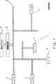
図1に、Echelon Corporationに譲渡された米国特許5,454,008(Baumannら)に記載されるような、典型的なネットワーク・コンフィギュレーション1を示す。セルは複数のノード2によって示し、ノードは撚線対3によって互いに接続している。線は多数の分岐を形成し、それぞれに単一のノードが接続されて、すべて中央の電力サプライ4から撚線対を通って電力を受ける。電力サプライ4は電源結合器5(source coupler)を通ってネットワークと接続する。このような配置においては、それぞれのノードは有効な線成端(line termination)を形成するため、追加分岐を必要に応じて接続して、新しいノードでそれぞれの分岐を終端させれば、より多くのノードをネットワーク内に収める(accommodated)ことができる。
このネットワーク・コンフィギュレーションでは、既知の星型トポロジー(star topologies)に比べ、ケーブリング・オーバーヘッド(cabling overhead)を少なくすることで、追加ノードを収納するための拡張(extension)が比較的容易にできる。しかし、図1に示すバス・トポロジーの場合、それぞれのセルあるいはノードを個々にアドレスするには、複雑なアドレス操作(addressing)が必要である。さらに、伝送ノード(transmistting node)は全ネットワークをつなぐ(ties up)ため、2つ以上のノードが同時にデータ伝送を行うのを妨げることになる。
さらに、上記米国特許4,918,690ならびにその他の先行技術のノードあるいはセルは一般に中央管理方式(centralized management)を採用しており、そのため各ノードはノード自体にとっては外部の論理に従って作動している。
記述したような制御ネットワークの展開は、これもEchelon Corporationに譲渡された米国特許5,148,144(Sutterlinら)に記載される方式によるデータの電力信号へのスーパーインポジション(superimposition of data on a power signal)に端を発している。このようなトポロジーは、各電力出口(power outlet)が中央分電盤(central distribution board)に放射状に接続される、放射状すなわち星型トポロジーを主として採用してきた家庭用ならびに産業用配線分配システム(wiring distribution system)のトポロジーによって決まる。したがって、このようなシステムにおいては、それぞれのセルをそれぞれの電力出口に結合するようにすると、星型トポロジーをもつ非分散型ネットワークを必然的に形成することになる。
先行技術のコンフィギュレーションにいくつかの欠点があることは明白であろう。一般に、通信はあるセルの出力(output)と、これに接続された複数のセルの対応する入力(input)との間で成立(effected)する。これはシステム内での限定的なデータ伝送(limited data transfer)という結果をもたらす。さらに、ネットワークの一部に結合されたノイズなど(noise coupled to a part of the network)、通信に問題がある場合、いくつかのセルが並列接続していて、ノイズがネットワーク全体の劣化をもたらすため、問題の出所を突き止めるのがより困難になる。
加えて、このようなコンフィギュレーションでは、隣りあう分岐間の接合部(junction)で入手可能な電力が分割(split)され、各分岐に届くのは電源から供給されるパワーの一部にすぎないため、コンフィギュレーションは電力不足(power-limited)になる。
最後に、先に述べたように、製造過程でセルに焼き付けるか(burnt into)あるいは設置時に手で取り付けるかした固有IDを用いてアドレスしなければならない。これには、各セルのネットワーク内での位置があらかじめコントローラーにわかるようにコントローラーをプログラムしなければならないため、ネットワークの柔軟性が失われる。そのため、セルを互いに交換する、追加する、取り除くなどすると、それに応じてコントローラを再度プログラムし直さなければならず、この種のトポロジーではリアルタイムで処理中に「その場で」(“on the fly”)アドレスを割り当てるための用意がない。
米国特許5,535,336(Smithら)にも、基本的には電力とデータをネットワーク中の別個の線に沿って通信するためのバストポロジーを用いるコンピューターネットワークが記載されている。ネットワーク中のノードを電気的に相互に区別できないことから生じる、バストポロジーにまつわるアドレス操作の問題に対応するために、追加の「デージーチェーン」接続ネットワークを設けて、初期化中のパワーオン時に(up on powe-on during initilization)ネットワーク中のすべてのセルに対する「1回きり」(one time only)の制御信号伝送を可能にする。これにより、ネットワークセルに論理的アドレス(logical addresses)を割り付ける(assign)ことができ、製造時あるいはシステムインスタレーションの一環として手動で、固有アドレスをあらかじめ割り付ける(pre-assign)必要がなくなる。
Smithらが記述するネットワークや、その他バストポロジーに基づくデータ伝送など、類似のネットワークにまつわる主な欠点は、2つのセル間の通信が、ワイヤ不足(short in the wires)あるいは過剰誘導ノイズ(exessive induced noise)のために落ちる(fall)場合、ネットワーク全体が崩壊することである。このことはネットワークの通信経路(communication paths)間の依存性を強めることになり、その結果ネットワークの異なる区分(different segments of the network)が独立の動作ができなくなる。
従来技術によるネットワークは、ある特定のセルが独立して1つ以上の隣接セルと通信できるようにするために、2つの独立した通信経路(communication routes)を同時に採用できるような仕組みになっていない。
これら欠点はネットワークの無防備性(vulnerability)にさらに衝撃を加える(further impinges on the network vulnerability)。ネットワーク中のいずれか2つの導電体にまたがる単一のショートの場合(single short across the two conductors anywhere in the network)、Smithらのネットワークは崩壊し、そのシステムではそれ以上通信ができなくなる。さらに、既知の従来ネットワークでは、誤りの箇所を切り離す(isolate)のが難しい。
発明の要旨
したがって本発明の目的は、外部の制御マネジャーのかわりに、あるいはこれに加えて、セル内に一体的に記憶させた(stored integrally therein)制御論理によって各セルを制御できるようにし、かつセルを直列接続させてケーブル配線(cabling)を少なくできるようにした、分散型トポロジー(distributed topology)を提供することにある。
これらの目的は、分散型検出、制御、通信(distributed sensing, control and communication)を可能にするネットワークトポロジーにより、本発明の好ましい実施例にしたっがて実現できるものであり、
電源と、
少なくとも3つのラインパワード直列インテリジェントセル(line-Powered, Serially connected Intelligent Cells(PSICs))であって、そのうち少なくとも一つは電源によって直接付勢(energized)され、前記PSICはそれぞれ少なくとも2つの導電体(electrical conductors)を具備する通信チャンネルを介してデージーチェーンフォーメーションをなして互いに結合される(coupled to the power source and to each other)インテリジェントセルと、
各PSIC内にあって、固有に参照符をつける(uniquely referencing)ためのアドレス手段と、
PSICの少なくとも一つは、前記PSICの一つに埋設されるか、又は供給される制御論理に従って作動するためにPSICに結合されたペイロード素子を1つ以上持ち、
PSICの少なくとも一つは、それぞれ隣接するPSICとは相互に独立した通信を、それぞれの通信チャンネルを介して実行するために、個別に制御される専用通信ポートを2つ以上持ち、
通信チャンネルの少なくとも一つは、双方向通信が可能である
ことを特徴とする。
セルの直列接続を可能にするこのようなトポロジーを用いることで、一つのセルと隣接するセルとの間でいずれの方向にもデータを送ることができる。
さらに、ある一組の隣接セル間の通信は、他の隣接セル間で同時に行われる通信とは独立している。これは星型あるいはバストポロジー(bus topology)を用いる従来システムではもちろん不可能である。
本発明の一実施例によれば、制御データは電力信号にスーパーインポーズされ、各セル内においてネットワーク内の先行セル(preceding cell)から受取られる電力信号から抽出されて、同じようにネットワーク内の後続セル(succeeding cell)に供給される電力信号にスーパーインポーズされる。
あるいは、バス型配置のネットワークの全セルに直接電力を供給し、データだけ直列式にセルからセルへ、いずれか一方または双方向に供給してもよい。
【図面の簡単な説明】
本発明を理解し、実地での実施方法を知るために、ここで好ましい実施例をいくつか非制限的な例を通して、かつ添付図面を参照して、説明する。図中、
図1は、典型的な従来技術による分散型ネットワークを概略的に示す。
図2は、本発明による分散型ネットワークを概略的に示す。
図3は、図1のネットワークで用いられるPSICの主要構成部品を機能的に示すブロック図である。
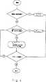
図4は、かかるネットワークにおける個々のPSICのアドレス操作を行うための主要操作ステップを示すフロー図である。
好ましい実施例の詳細な説明
図2は、全体を10で表す分散型インテリジェントネットワークを示すもので、ネットワークはラインパワード直列インテリジェントセル(PSIC)13と、撚線対12を介して来れに電力を供給する電源11を具備し、PSIC13はそれぞれ(双方向通信チャンネルを構成する)撚線対18、19、10を介して他のPSIC14、15、16、17と直列に接続している。
以下の説明の目的上、PSIC13、14、15、16、17はそれぞれ第1、第2、第3、第4、第5PSICとするが、事実、PSICはこの順序で個別にアドレスされ、その結果撚線対によって構成される双方向通信チャンネルに沿っていずれかの方向に逐次伝送されるデータは、適切なPSICとの間で正しくやり取りされる
センサー22が、第1PSIC13の入力に接続され、一対のセンサー23、24が、第3PSIC15のそれぞれの入力に、センサー25が第4PSIC15の入力の一つに接続される。同様に、一対のアクチュエータ26、27が第2PSIC14のそれぞれの出力に、アクチュエータ28が第5PSIC17の出力に接続される。マネジャー29は第3PSIC15の入力に結合されて、ネットワーク内の他のPSICに制御データを経由させる方法ならびに、これに結合されているアクチュエータを制御する方法をPSICに指示(direct)するために、所定(predetermined)の論理をネットワークに供給し、またネットワークのPSIC、アクチュエータ、センサーの状態をモニターする、外部論理制御とモニター素子を構成している。
PSICの動作(operation)とアドレス操作(addressing)1を説明する前に、図2を参照してPSICの一般的な特長をいくつか明記しておく。まず、PSIC13乃至17は必ずしも同一ではない。たとえば、第1のPSIC13は、第2PSICの入力に接続する出力と第4PSIC16の入力に接続する出力の2つの出力を持つ。他方、PSICはすべて、単一の電力入力しか持たないことを特徴とする。第2に、PSICに任意でセンサーまたはアクチュエータを接続してもよく、あるいはまた第4PSIC16のようにまったく何も接続しなくてもよい。PSICにペイロード素子が接続されていない場合は、そのPSICは通信チャンネル上の電力/データ信号を増幅して、長大な通信線上で信号が減衰するのを補償(compensate for)するための中継器(repeater)として機能する。普通長大な通信チャンネル全体に間隔を置いて設けられるこうした中継器は、それ自体公知であり、例えば上記で引用したBaumannらに対する米国特許5,454,008に記載されている。
第3に、マネジャー29により構成される外部論理制御ユニットは、任意でネットワーク10のPSICの一つに接続することができる点に注目されたい。その場合、マネジャー29は各PSICに記憶されたディスクリート論理(discrete logic)を補完(supplement)することができ、あるいは必要であれば、PSIC内に設けるべき内部論理を省くこともできる。非常に単純なシステムでは、例えば、センサー22を光依存抵抗子(lilght dependent resistor)とし、アクチュエーター28をPSIC17によって制御される照明灯(illumination light)にして、センサー22に投下される照明レベルの関数としての照明灯照度(brightness of illumination lamp)を制御することもできる。その場合、アクチュエーター28は必要な照明レベルを表す制御信号に呼応することになり、この信号はPSIC17に内包される(contained the rein)ローカル論理(local logic)、またはマネジャー29からネットワーク10を通って伝送される論理、あるいはまたこれらの組合せに基づいて第5PSIC17により生成される。
いずれのアプローチによる場合でも、センサー22で生成されセンサー信号を表すデータは、第2、第3PSIC14、15をそれぞれ介して、第1PSIC13によってマネジャー29に、また第4PSIC16を介して第5PSIC17に供給される。このようにして、マネジャー29およびアクチュエーター28が接続された第5PSIC17は、センサー22の照明レベルに呼応してアクチュエーター28を制御するための正しい制御信号を生成する。第5PSIC17がマネジャー29によって制御される場合は、制御信号は撚線対19と18に沿って、第1PSIC13に逐次供給され、第1PSIC13から撚線対20、21に沿って、逐次第5PSIC17に供給される。いずれの場合も、状態データ(status data)がネットワーク内の各PSICによってマネジャー29に供給されることで、マネジャー29はネットワーク10内のすべてのセンサーとアクチュエーターの状態をモニターすることができる。
したがって、このような単純なシステムの場合、アクチュエーター28はセンサー信号に呼応するが、この信号自体はアクチュエーター28から離れた場所で生成されるものでもよいことに留意されたい。他方、必要であれば、アクチュエーターをアクチュエーターと同じPSICに接続したセンサーに呼応するようにしてもよい。事実、多重センサー(multiple sensors)と多重アクチュエーター(multiple actuators)を同一PSICに接続することもできるが、ただし十分なセンサーと、アクチュエーターインターフェースがその中に設けられていることが条件であることは言うまでもない。
第1PSIC13ならびに第3、第5PSIC15、17(これらはそれぞれの分岐の最後のPSICである)を除き、ネットワーク内のすべてのPSICは先行PSIC(a preceding PSIC)から電力ならびにデータを受取り、電力とデータを後続PSIC(a succeeding PSIC)に供給する。第3、第5PSIC15、17はもちろん、それぞれ別のPSICと接続するためのインターフェースを具備していてよいが、実際にはこのインターフェースは使われない。しかし、第1PSIC13は、電力を電源11から受けるものの、データはここから受けないという点で他のPSICとは異なっている。同じように、後続PSICから受取るデータを電源11に供給することはない。このことから、第1PSIC13は一般的なPSICアーキテクチャーを完全に具現しておらず、このアーキテクチャーについては第2PSIC14についてよりよく説明されている。
図3は、電力とデータが一緒に伝送される場合に、PSIC14に設けられる機能構成部品(functional components)を示すブロック図である。データ通信ネットワーク内で電力とデータを同一ケーブル束(cable bundle)によりデータ通信ネットワーク内の複数の通信ノードに送る方法そのものは既知であり、先に説明したSutterlinらの米国特許5,148,144の冒頭部分に記述される電話方式でも長年用いられている。
第2PSIC14は、第1PSIC13と結合することで、ここから第1の入力電力とデータ信号をうけとる第1のポートを構成するラインインターフェース30を含む。入力する結合信号(incoming combined signal)は、入力電力信号からの第1の入力データ信号を減結合(decouple)させる電力/データ結合器/減結合器31に送られる。分離された(separated)第1のデータ信号は、モデム32に送られ、直流または交流電力信号そのものは電力ハンドリングユニット33に送られて、ここから第1の出力電力信号を生成して、これに結合された電力サプライ34に電力を供給し、電力サプライ34は必要に応じていくつかの出力チャンネルを持っていて、PSIC14内のローカル回路(local circuitry)に電力を与える(powering)。
モデム32で受取った第1の入力データ信号はアナログであり、デジタルの形に変換されて処理制御ユニット35に送られ、処理制御ユニット35はこの第1入力データ信号を、ユニットに記憶させた制御論理に従って、あるいはこれに代えてまたはこれに加えて、処理制御ユニット35に結合された通信ポート36を介して36マネジャー29によって、処理制御ユニット35に供給される外部論理に従って、処理する。
同様に、処理制御ユニット35はそれぞれのセンサーインターフェース37を介してユニット35に送られるさまざまなセンサー信号に呼応することもでき、上記で説明したように、それぞれのアクチュエーターを処理制御ユニット結合させるために、複数のアクチュエーターインターフェース38に処理制御ユニット35を結合させてもよい。
処理制御ユニット35は第1の入力データ信号を処理して、第1の出力データ信号を生成し、この信号はモデム39によってアナログ信号に変換されて第2の電力/データ結合器/減結合器40(第2の結合/減結合手段を構成する)に送られ、第2の電力/データ結合器/減結合器40は、交流又は直流電力信号を第2の電力/データ結合器/減結合器40が結合されている電力ハンドリングユニット33から受取り、第1の出力データ信号を第1の出力電力信号と結合して(combines)、第1の出力電力/データ信号を生成し、この信号はラインインターフェース41に送られる。ラインインターフェース41は第2のポートを構成していて、PSIC14と対応する後続PSICとの接続を可能にしている。必要であれば、それぞれがモデム39と第2の電力/データ結合器/減結合器40に接続させたラインインターフェース41を具備した、対応する第2のポートを介して、多数のPSICをPSIC14に結合させることもできる。
上記の配置では、センサーインターフェース37とアクチュエーターインターフェース38はそれぞれペイロードポートを構成していて、それぞれのペイロード素子を処理制御ユニット35に接続することを可能にしている。
それぞれのアクチュエーターインターフェース38を介して処理制御ユニット35に接続されるさまざまなアクチュエーターと、場合によっては(possibly)、それぞれのセンサーインターフェース37を介してこれに接続されるセンサーの少なくともいくつかに対しても、効果的な操作のために処理制御ユニット35によって生成されるデータ信号に加え、電力信号も供給する必要があることが明らかであろう。この目的のために、センサーインターフェース37とアクチュエーターインターフェース38はそれぞれ、対応するペイロードパワーインターフェース42と関連しており(associated)、ペイロードパワーインターフェース42自体は、電力ハンドリングユニット33と結合するとともに、処理制御ユニット35から制御信号を受取ってモニター信号をこのユニット35に送信するために処理制御ユニット35に作動可能に(operatively)結合されている。このような手段により、各センサー、アクチュエーターの要件に対応するさまざまな電圧レベルが、処理制御ユニット35内の制御論理にしたがって、あるいは外部からマネジャー29を介してユニットに印加される制御論理にしたがって、対応するインターフェースに正しく与えられる。
上記説明では、ラインインターフェース30は第1入力電力とデータ信号が供給される受信インターフェース(receiving interface)とみなされており、一方ラインインターフェース41は対応する第1出力電力とデータ信号を、これに接続される後続PSICに供給する。しかし、上記でみてきたように、ネットワーク10内の通信チャンネルは双方向性であり、PSIC14はそのため、同じように後続PSICからの第2の入力データ信号を受取るのに適している。この場合、電力/データ結合器/減結合器40は、第1の出力電力信号からの第2の入力データ信号を減結合させ、モデム39は、処理制御ユニットに供給するために、アナログの第2入力データ信号をデジタル信号に変換する。モデム32はついで、デジタル信号をアナログ信号に再変換し、電力/データ結合器/減結合器31がアナログ信号を入力電力信号にスーパーインポーズして、第2出力信号をラインインターフェース30に供給する。
したがって、第1モデム32が第1入力データ信号と第2出力データ信号の同時二重ハンドリング(full duplex handling)を可能にする一方、同時に、第2モデム39が第1出力データ信号と第2入力データ信号の同時二重ハンドリングを可能にすることがわかる。したがって、PSIC14は4種類の独立した通信を同時に実行できる。
本発明はPSICを直列接続することで、PSICの一つから前後いずれかの方向に隣り合うPSICにデータを送ることができるという特徴を持つが、データを電力信号にスーパーインンポーズさせることは要件ではない。必要であれば、電力は共通の電力バスを介してネットワークのPSICそれぞれに供給することもでき、あるいは、既知の星型トポロジーを用いて放射状に各PSICに供給してもよい。いずれの場合も、電力信号、データ信号はディスクリートに扱われる(discretely handled)ため、電力/データ結合器/減結合器31、40は省略することができる。事実、データと電力が同じ撚線対によって供給される場合でも、第1PSIC13は電源11から電力のみをうけとり、一方データは第2PSIC14を介してのみ第1PSIC13に供給されることがわかる。この目的のために、先に指摘したように、第1PSIC13の内部アーキテクチャーの一部は、他のPSICのものとは異なっている。特に、電力信号は電力ハンドリングユニット33に直接供給されるため、電力/データ結合器/減結合器31は省略してもよい。同じような理由から、必要であれば、最後のPSIC(すなわち、図2に示す例では第5PSIC17)には後続PSICが接続されていないので、この中の電力/データ結合器/減結合器40は省略できる。他方、ネットワークを拡張する必要がある場合は、簡略化した第5PSIC17は電力/データ結合器/減結合器40に接続したラインインターフェース41を持つものと交換する必要がある。
PSICの内部アーキテクチャーを説明し終わったところで、そのアドレス操作を説明する。アドレスを行うと、受取り側PSIC(receiving PSIC)はデータをどの後続PSICを経由(to route)させればよいかがわかり、またどのセンサーからデータが送られたのかを特定する。この目的のために、各データパケット(data packet)は、本技術分野で周知の通り、所定のプロトコールに従って発信源(source)と目的地(destination)アドレスを定義するヘッダーを含んでいる。
図4は、ネットワークのトポロジーに従って、ネットワーク10に示すPSICのそれぞれを、ディスクリート(discretely)にかつ個別にアドレスする際の主要ステップをフロー図として示す。ネットワークトポロジーによって、第1、第2、第3PSIC13、14、15で構成される主分岐のPSICの数が決まる。第1PSIC13は電源11に直接接続されていることを「確かめ」(“sees”)、自らに内部アドレスI=1を割り当てる(assigns)。これに続く(subsequent)PSICは、PSICが先行PSICの第1出力に、あるいは分岐が2つしかない単純なケースではその第2出力に、接続されているかどうかによって作動する。この場合、先行PSICの第1出力に接続されているPSICは、先行PSICのインデックス+1、すなわちIN-1+1に等しい内部アドレスINを自らに割り当てる。
他方、現行PSICが先行PSICの第1出力に接続されていない場合、図2に示すネットワーク10の場合のように分岐が2つしかないと仮定して、現行PSICのインデックスINは1プラス主分岐のPSICの数に設定される。その結果、主分岐に3つのPSIC(13、14、15)を持つネットワーク10では、第4PSICのインデックスは(1+3)すなわち4に設定される。
図4に示す論理が、図2に示す特定ネットワーク構成に適合させたものであるが、しかし追加分岐が設けられる場合、簡単な適応構造(simple adaptation)に修正可能であることが明らかであろう。このプロセスは、たとえばシステムのパワリングアップに当たって(on powering up the system)独立して実施できる。
図4に関連して説明したような論理を採用することの利点は、アドレス操作論理(addressing logic)を変える必要が全くないまま、第4、第5PSIC16、17からなる第2分岐にPSICを追加したり除去したりできる点である。事実、分岐が一つしかないより単純な場合では、上記のようなアドレス論理を用いることで、単一の分岐からPSICを容易に追加したり除去したりでき、ネットワークが完全にフレキシブルになる。
アドレス操作論理を得る他の方法として、各PSICにエンコーダを設け、マネジャー29が設けられている場合はマネジャー29にも知られている(known also to the Manager 29)ディスクリートアドレスに手動で設定する。エンコーダはネットワークカード(network cards)で普通に用いられるDIPスイッチの形式を取ってもよく、あるいROMに記憶させた固有のアドレスコードの形式であってもよい。必要であれば、組み合わせを用いることで、アドレスコードの一部をPSIC内部に記憶させるとともに、他のアドレスを図4に示す論理に従ってネットワークトポロジーに基づいて「その場で」(on the fly)割り当てることもできる。このような配置は多数の分岐が用いられているような場合に特に好適であって、その結果、たとえば各分岐の第1PSICは、これに続く分岐における第1PSICのそれぞれのアドレスと矛盾することなく、PSICをさらに追加できるように適切にオフセットされた特定アドレスをプログラムしたハードウェアとすることができる。たとえば、第1分岐の第1PSIC13には通常の方法で1というアドレスを与える一方、第2分岐の第1PSIC16には100に等しいアドレスを与えることができる。これにより、第2分岐の第1PSIC16にあらかじめ設定したアドレスと矛盾することなく、最大96の追加PSICを主分岐に接続することができる。ここまで終えたところで、各分岐のPSICそれぞれのアドレス操作(addressing of each of the PSICs)を、図4に関連して説明した上記ネットワークトポロジーに基づいて決定することができる。
マネジャー29の形式で外部制御ユニットが設けられている場合は、29はあらかじめプログラムしておくことで、マネジャー29がPSICのぞれぞれについていかなる行動(action)を取るべきかを知ること、その目的のためには、各分岐の第1PSICについて知っている(is a ware of the first PSIC)ことが必要であることは明らかである。しかし、マネジャー29が省略されているような場合には、それぞれのPSICは自身のアドレスを知っているだけでよく、各PSICに接続されている1つ又はそれ以上のアクチュエーターを作動させるために各PSICに送られるデータは、正しいPSICアドレスによって適切にエンコードされる。
多数のセンサーやアクチュエーターをPSICに接続することについて、典型的なネットワークを通して一般性をもたせて説明してきた。しかし、本発明は発明から逸脱することなく修正を行うことを想定していることが理解される。たとえば、最も単純な形をとった場合、ネットワークにはペイロード素子を一つ設けるだけでよい。これをアクチュエーターにして、このアクチュエーターが接続されるPSIC、あるいはその中に論理が記憶されたPSICに供給される論理に呼応するようにしてもよい。あるいは、このペイロード素子としてセンサーを用い、このセンサーが生成するセンサー信号によってネットワーク中の異なるPSICに、それぞれの制御信号を中継する(for relaying a respective control signal)ようにしてもよい。このような配置は、たとえば、ネットワークで生成される制御信号に呼応するアクチュエーターをもつ遠隔システムにネットワークを結合させるのに有用であろう。また、センサーはセンサーの状態に従って1つ以上の固定出力信号を生成するものであればどのような装置(device)でもよい。したがってたとえば、センサーはどのスイッチ位置が選択されたかによって出力が決まる手動セレクタースイッチでもよい。
処理制御ユニットによって生成される制御信号は、ネットワークに直接あるいは間接に接続されたデータベースに最終的に入力されるデータによって、その一部又は全部を構成されていてもよいことは理解される。
また、本発明は特に双方向データ通信に適しているが、必要であれば、一方向のみにデータを供給するためにネットワークを利用できることも理解される。
さらにまた、本発明と添付のクレームの文脈内において、PSICについて用いられる「先行する」という語句は隣接PSICに結合され、これに電力を供給するPSICを表すことに留意されたい。同じように、PSICについて用いられる「後続」なる語句は、隣接するPSICに結合されてこれから電力を受取るためのPSICを表す。
本発明はこのように、複数のインテリジェントセルが双方向通信チャンネルを介して直列に接続されて、データ(ならびに任意で電力)をネットワークに沿ってPSICの一つから他のPSICに任意でいずれの方向にも供給できるようになっているインテリジェント分散型ネットワーク(intelligent,distributed network)を提供する。Field of Invention
The present invention relates to wired communication and control systems, and in particular, simultaneous distribution of power and message information along the same line in a network having a plurality of sensors, actuators and processing elements. It is related with the apparatus which brings about.
Background of the Invention
What is known as a distributed control system includes several intelligent “cells” that provide power and data, which are external to one or more sensors, actuators, etc. Payload elements are coupled, and in the cell, the actuator operates in response to a control signal generated by the processor, and the processor itself is responsive to the data signal and the sensor signal generated by the sensor.
Such networks are found, for example, in US Pat. No. 4,918,690 (Markkula, Jr. et al.) Assigned to Echelon Corporation, but there are several other US patents in the name of Echelon Corporation regarding this technology. Each programmable cell is given a unique 48-bit identification number (ID) during the manufacturing process, and this number remains unchanged in the cell. Cells can be coupled to different media, such as power lines, twisted pair, radio frequency, etc., to form a network.
The cells in the network form a group and perform a specific function and are addressed through their respective IDs. For example, a part of the cell (announcer) is given a task of detecting the state of the switch, and the other cell (listener)) has a task such as control of light. These cells can perform multiple tasks and can be members of different groups in the network. For example, a cell can function as a repeater for some groups and as a listener for other groups.
FIG. 1 shows a
In this network configuration, extensions to accommodate additional nodes can be made relatively easy by reducing cabling overhead compared to known star topologies. . However, in the case of the bus topology shown in FIG. 1, complex addressing is required to address each cell or node individually. In addition, transmission nodes (ties up) connect the entire network and prevent two or more nodes from transmitting data simultaneously.
Further, the above U.S. Pat. No. 4,918,690 and other prior art nodes or cells generally employ centralized management, so that each node operates according to external logic for the node itself. .
The development of the control network as described is based on the superimposition of data on a data to a power signal in the manner described in US Pat. No. 5,148,144 (Sutterlin et al.), Also assigned to Echelon Corporation. power signal). Such a topology is a household and industrial wiring distribution system that has mainly adopted a radial or star topology, where each power outlet is connected radially to a central distribution board. distribution system) topology. Thus, in such a system, coupling each cell to its respective power outlet will inevitably form a non-distributed network with a star topology.
It will be apparent that the prior art configuration has several drawbacks. In general, communication is effected between an output of a cell and corresponding inputs of a plurality of cells connected to the cell. This results in limited data transfer within the system. In addition, if there is a communication problem, such as noise coupled to a part of the network, several cells are connected in parallel, and the noise causes the entire network to deteriorate. , Making it harder to find the source of the problem.
In addition, in such a configuration, the power available at the junction between adjacent branches is split, and only a portion of the power supplied from the power source reaches each branch. As a result, the configuration is power-limited.
Finally, as described above, it must be addressed using a unique ID that is either burnt into the cell during manufacturing or manually attached during installation. This loses the flexibility of the network because the controller must be programmed so that the controller knows in advance the location of each cell in the network. Therefore, if the cells are swapped, added, removed, etc., the controller must be re-programmed accordingly, and this type of topology “on the fly” during processing in real time. ) There is no provision for assigning addresses.
US Pat. No. 5,535,336 (Smith et al.) Also describes a computer network that uses a bus topology to basically communicate power and data along separate lines in the network. To address the addressing issues around the bus topology that result from the inability of the nodes in the network to be electrically distinguished from each other, an additional “daisy chain” connection network is provided to allow for power up during initialization (up on powe-on during initilization) Enables "one time only" control signal transmission to all cells in the network. Thereby, logical addresses can be assigned to network cells (assign), and it is not necessary to pre-assign unique addresses at the time of manufacturing or manually as part of system installation.
The main drawbacks of similar networks, such as the network described by Smith et al. And other data transmissions based on bus topology, are that communication between two cells is short in the wires or excessive induced noise. ) Falls for the whole network to collapse. This increases the dependency between the communication paths of the network, and as a result, different segments of the network cannot operate independently.
Prior art networks are not designed to allow two independent communication routes to be employed simultaneously to allow a particular cell to communicate independently with one or more neighboring cells. .
These shortcomings have a further impact on the vulnerability of the network (further impinges on the network vulnerability). In the case of a single short across the two conductors anywhere in the network, Smith et al.CollapseHowever, the system can no longer communicate. Furthermore, it is difficult to isolate the location of the error in the known conventional network.
Summary of the Invention
Accordingly, it is an object of the present invention to allow each cell to be controlled by control logic stored within the cell instead of or in addition to an external control manager, and to connect the cells in series. The purpose is to provide a distributed topology that can be connected to reduce cabling.
These objectives can be realized according to a preferred embodiment of the present invention by means of a network topology that enables distributed sensing, control and communication,
Power supply,
At least three line-powered, serially connected intelligent cells (PSICs), at least one of which is directly energized by a power source, each of the PSICs having at least two conductors ( intelligent cells coupled to the power source and to each other via communication channels with electrical conductors),
An addressing means within each PSIC for uniquely referencing;
At least one of the PSICs has one or more payload elements that are embedded in one of the PSICs or coupled to the PSIC to operate according to the supplied control logic;
At least one of the PSICs has two or more dedicated communication ports that are individually controlled in order to perform communication independent from each other adjacent PSIC through each communication channel,
At least one of the communication channels is capable of bidirectional communication
It is characterized by that.
By using such a topology that allows cells to be connected in series, data can be sent in either direction between one cell and an adjacent cell.
Further, communication between a certain set of adjacent cells is independent of communication performed simultaneously between other adjacent cells. This is of course not possible with conventional systems using a star or bus topology.
According to one embodiment of the present invention, control data is superimposed on a power signal and extracted from a power signal received from a preceding cell in the network within each cell, as well as within the network. Superimposed on the power signal supplied to the succeeding cell.
Alternatively, power may be supplied directly to all cells in a bus-type network, and only data may be supplied in series or from cell to cell in either or both directions.
[Brief description of the drawings]
In order to understand the present invention and know how to implement it in practice, a preferred embodiment will now be described through some non-limiting examples and with reference to the accompanying drawings. In the figure,
FIG. 1 schematically illustrates a typical prior art distributed network.
FIG. 2 schematically shows a distributed network according to the invention.
FIG. 3 is a block diagram functionally showing the main components of the PSIC used in the network of FIG.
FIG. 4 is a flow diagram showing the main operation steps for addressing individual PSICs in such a network.
Detailed Description of the Preferred Embodiment
FIG. 2 shows a distributed intelligent network, generally designated 10, which comprises a line-powered serial intelligent cell (PSIC) 13 and a
For purposes of the following description,
The
Before describing the operation and addressing 1 of the PSIC, some general features of the PSIC are specified with reference to FIG. First, the
Thirdly, it should be noted that the external logic control unit configured by the
In either approach, the data generated by the
Thus, in such a simple system, it should be noted that the
Except for the
FIG. 3 is a block diagram illustrating functional components provided in
The
The first input data signal received by the
Similarly, the
The
In the above arrangement, the
Also for various actuators connected to the
In the above description, the
Thus, the
The present invention has a feature that by connecting PSICs in series, data can be sent from one of the PSICs to adjacent PSICs in either the front or back direction. However, superimposing data on a power signal is not possible. It is not a requirement. If desired, power can be supplied to each PSIC in the network via a common power bus, or can be supplied radially to each PSIC using a known star topology. In any case, the power / data coupler /
Now that we have described the internal architecture of the PSIC, the address operation will be described. Upon addressing, the receiving PSIC knows which subsequent PSIC the data should be routed to, and identifies which sensor the data was sent from. For this purpose, each data packet includes a header that defines a source and destination address according to a predetermined protocol, as is well known in the art.
FIG. 4 shows as a flow diagram the main steps in addressing each of the PSICs shown in the
On the other hand, if the current PSIC is not connected to the first output of the preceding PSIC, assuming that there are only two branches as in the
It will be clear that the logic shown in FIG. 4 is adapted to the specific network configuration shown in FIG. 2, but can be modified to a simple adaptation if additional branches are provided. . This process can be performed independently, for example, on powering up the system.
The advantage of employing the logic as described in connection with FIG. 4 is that the PSIC is added to the second branch consisting of the fourth and fifth PSICs 16 and 17 without having to change the addressing logic at all. It can be removed or removed. In fact, in the simpler case where there is only one branch, the use of address logic as described above can easily add or remove PSICs from a single branch, making the network completely flexible.
As another method for obtaining the address operation logic, an encoder is provided in each PSIC, and when the
If an external control unit is provided in the form of
The connection of a large number of sensors and actuators to the PSIC has been described with generality through a typical network. However, it is understood that the present invention contemplates modifications without departing from the invention. For example, in the simplest form, the network need only have one payload element. This may be an actuator that responds to the logic supplied to the PSIC to which the actuator is connected or to the PSIC in which the logic is stored. Alternatively, a sensor may be used as the payload element, and each control signal may be relayed to a different PSIC in the network by a sensor signal generated by the sensor. Such an arrangement may be useful, for example, for coupling the network to a remote system having actuators that respond to control signals generated by the network. The sensor may be any device that generates one or more fixed output signals according to the state of the sensor. Thus, for example, the sensor may be a manual selector switch whose output is determined by which switch position is selected.
It will be understood that the control signal generated by the processing control unit may be composed in part or in whole by data that is ultimately input into a database connected directly or indirectly to the network.
It will also be appreciated that although the present invention is particularly suitable for bi-directional data communication, a network can be utilized to provide data in only one direction, if necessary.
Furthermore, it should be noted that within the context of the present invention and the appended claims, the phrase “preceding” as used for PSIC refers to a PSIC that is coupled to and powers an adjacent PSIC. Similarly, the term “success” used for a PSIC represents a PSIC that is coupled to and receives power from an adjacent PSIC.
The present invention thus enables multiple intelligent cells to be connected in series via a bi-directional communication channel to transfer data (and optionally power) optionally from one PSIC to another PSIC along the network. Provide an intelligent, distributed network that can be supplied in any direction.
Claims (17)
Translated fromJapanese電源と、
複数のラインーパワード直列インテリジェントセル(PSICs)と、からなり、
PSICの少なくとも一つは、電源によって直接電力供給され、
PSICは、第1、第2及び第3のPSICを含み、
PSICは、それぞれの通信チャンネルを介してデージーチェーン構成として結合され、
PSICの各々は、固有のアドレスによって参照するためにその中にアドレス手段を持ち、
PSICの少なくとも一つは、制御論理に従って作動するために少なくとも一つのペイロード素子に関連付けられ、
PSICの少なくとも一つは、それぞれの通信チャンネルを介して、それぞれ隣接するPSICと相互に独立した通信を実行するために、少なくとも2つの別個に制御される専用通信ポートを持ち、
通信チャンネルの少なくとも一つは、双方向通信を可能にし、
第1のPSICは、
電源から入力電力信号を受取るよう構成された入力ポートと、
それぞれ、第2及び第3のPSICに結合するよう構成された第1及び第2のポートと、
それぞれ、第1及び第2のポートに結合された第1及び第2の手段と、を含み、
第1の手段は、データ信号を与えるために第1のポートから入力データ信号を受取るよう構成され、
第2の手段は、出力データ信号を出力電力信号にスーパーインポーズし、
出力データ信号及び出力電力信号は、出力電力及びデータ信号を生成するためにデータ信号及び入力電力信号から生じ、
第2のポートへ出力電力及びデータ信号を与えるよう構成される、
ネットワーク。Distributed detection,a networkfor control and communication,
Power supply,
A plurality of line-powered serial intelligent cells (PSICs),
At least one of the PSICs is directly powered by a power source,
The PSIC includes first, second and third PSICs,
PSICis engagedsintered in a daisy chain configuration via the communication channel oftheir respective,
Each PSIC has address means in it for reference by a unique address,
At least one PSICisassociated with at least one payload element to operate in accordance withcontrollogic,
At least one of the PSICs has atleast two separately controlled dedicated communication ports to perform communication independent of each other adjacent PSIC via respective communication channels,
At least one of the communication channels allows two-way communication,
The first PSIC is
An input port configured to receive an input power signal from a power source;
First and second ports configured to couple to the second and third PSICs, respectively;
First and second means coupled to the first and second ports, respectively,
The first means is configured to receive an input data signal from the first port to provide a data signal;
The second means superimposes the output data signal to the output power signal,
The output data signal and the output power signal result from the data signal and the input power signal to generate the output power and data signal,
Configured to provide output power and data signals to the second port;
Network.
制御論理が呼応して制御データを少なくとも一つの他のPSICを経由させるセンサー信号を与えるためのセンサーと、
PSICに供給される制御データに呼応して作動するためにPSICの一つに結合されたアクチュエーターと
のうち少なくとも一つを含む、請求項3のネットワーク。At least one payload element is
A sensor for providing sensor signals in response to control logic to route control data through at least one other PSIC;
An actuator coupled to one of the PSICs to operate in response to control data supplied to the PSIC;
Comprising at least one of, thenetworkof claim3.
電源と、Power supply,
複数のライン−パワード直列インテリジェントセル(PSICs)と、からなり、A plurality of line-powered serial intelligent cells (PSICs),
PSICの少なくとも一つは、電源によって直接電力供給され、At least one of the PSICs is directly powered by a power source,
PSICは、第1、第2及び第3のPSICを含み、The PSIC includes first, second and third PSICs,
PSICは、それぞれの通信チャンネルを介してデージーチェーン構成として結合され、PSICs are combined in a daisy chain configuration via their respective communication channels,
PSICの各々は、固有のアドレスによって参照するためにその中にアドレス手段を持ち、Each PSIC has address means in it for reference by a unique address,
PSICの少なくとも一つは、制御論理に従って作動するために少なくとも一つのペイロード素子に関連付けられ、At least one of the PSICs is associated with at least one payload element to operate according to control logic;
PSICの少なくとも一つは、それぞれの通信チャンネルを介して、それぞれ隣接するPSICと相互に独立した通信を実行するために、少なくとも2つの別個に制御される専用通信ポートを持ち、At least one of the PSICs has at least two separately controlled dedicated communication ports to perform communication independent of each other adjacent PSIC via respective communication channels,
通信チャンネルの少なくとも一つは、双方向通信を可能にし、At least one of the communication channels allows two-way communication,
電力及びデータは、通信チャンネル上でともに供給され、Power and data are supplied together on the communication channel,
第2のPSICは、The second PSIC is
第1のPSICから入力信号を受取るよう構成された第1のポートと、A first port configured to receive an input signal from a first PSIC;
受取った入力信号に呼応して入力データ信号及び入力電力信号を出力するよう構成された第1の手段と、First means configured to output an input data signal and an input power signal in response to the received input signal;
入力データ信号に呼応して処理されたデータ信号を与えるよう構成された処理手段と、Processing means configured to provide a processed data signal in response to an input data signal;
それぞれ、処理されたデータ信号及び入力電力信号から生じた出力データ信号及び出力電力信号を含む出力信号を出力するよう構成された第2の手段と、Second means configured to output an output signal including an output data signal and an output power signal, respectively, resulting from the processed data signal and the input power signal;
第3のPSICに出力信号を与えるよう構成された第2のポートと、を含むA second port configured to provide an output signal to the third PSIC.
ネットワーク。network.
処理手段からアクチュエーターに制御信号を与えるか、又はGiving a control signal to the actuator from the processing means, or
センサーからセンサー信号を受取り、センサー信号を処理手段に与えるよう構成される、請求項10のネットワーク。11. The network of claim 10, configured to receive a sensor signal from a sensor and provide the sensor signal to a processing means.
外部論理制御素子に結合して、処理手段の状態をモニターするために処理手段に結合された通信ポート、及びそれに結合されたペイロード素子、又はA communication port coupled to the processing means for monitoring the status of the processing means coupled to an external logic control element, and a payload element coupled thereto, or
外部論理制御素子に結合して、前記所定の論理を処理手段に供給し、処理手段の状態をモニターするために処理手段に結合された通信ポート、及びそれに結合されたペイロード素子をさらに含む、請求項11のネットワーク。And further comprising a communication port coupled to the processing means for coupling the external logic control element to supply the predetermined logic to the processing means and monitoring the status of the processing means, and a payload element coupled thereto. Item 11. The network according to Item 11.
第2の手段は、受取ったもう一つの入力信号に呼応してもう一つの入力データ信号を出力するよう構成され、The second means is configured to output another input data signal in response to the other input signal received;
処理手段は、もう一つの入力データ信号に呼応してもう一つの処理されたデータ信号を与えるよう構成され、The processing means is configured to provide another processed data signal in response to another input data signal;
第1の手段は、それぞれ、もう一つの処理されたデータ信号及び入力電力信号から生じたもう一つの出力データ信号及びもう一つの出力電力信号を含むもう一つの出力信号を出力するよう構成され、The first means is configured to output another output signal that includes another output data signal and another output power signal, respectively, resulting from another processed data signal and the input power signal, respectively.
第1のポートは、第1のPSICにもう一つの出力信号を与えるよう構成される、請求項9から12のうち何れか1項のネットワーク。13. A network as claimed in any one of claims 9 to 12, wherein the first port is configured to provide another output signal to the first PSIC.
電源と、Power supply,
複数のライン−パワード直列インテリジェントセル(PSICs)と、からなり、A plurality of line-powered serial intelligent cells (PSICs),
PSICの少なくとも一つは、電源によって直接電力供給され、At least one of the PSICs is directly powered by a power source,
PSICは、第1、第2及び第3のPSICを含み、The PSIC includes first, second and third PSICs,
PSICは、それぞれの通信チャンネルを介してデージーチェーン構成として結合され、PSICs are combined in a daisy chain configuration via their respective communication channels,
PSICの各々は、固有のアドレスによって参照するためにその中にアドレス手段を持ち、Each PSIC has address means in it for reference by a unique address,
PSICの少なくとも一つは、制御論理に従って作動するために少なくとも一つのペイロード素子に関連付けられ、At least one of the PSICs is associated with at least one payload element to operate according to control logic;
PSICの少なくとも一つは、それぞれの通信チャンネルを介して、それぞれ隣接するPSICと相互に独立した通信を実行するために、少なくとも2つの別個に制御される専用通信ポートを持ち、At least one of the PSICs has at least two separately controlled dedicated communication ports to perform communication independent of each other adjacent PSIC via respective communication channels,
通信チャンネルの少なくとも一つは、双方向通信を可能にし、At least one of the communication channels allows two-way communication,
電力及びデータは、異なるチャンネル上でPSICに供給され、Power and data are supplied to the PSIC on different channels,
第2のPSICは、The second PSIC is
第1のPSICから第1の入力データ信号を受取るよう構成され、Configured to receive a first input data signal from a first PSIC;
受取った第1の入力データ信号を受取り、所定の論理に従って制御信号を生成するよう構成された処理手段と、Processing means configured to receive a received first input data signal and generate a control signal according to a predetermined logic;
処理手段とペイロード素子との間の通信のためにペイロード素子を処理手段に結合するための第2のポートと、A second port for coupling the payload element to the processing means for communication between the processing means and the payload element;
第3のPSICに結合するための第3のポートと、A third port for coupling to a third PSIC;
処理手段及びペイロード素子へ電源によって電力を供給するための第4のポートと、を含むA fourth port for supplying power to the processing means and the payload element by a power source.
ネットワーク。network.
制御手段は、The control means
第2のポートを介してアクチュエーターに制御信号を与え、又はProviding a control signal to the actuator via the second port, or
第2のポートを介してセンサーからセンサー信号を受取る、請求項14のネットワーク。The network of claim 14, receiving a sensor signal from a sensor via a second port.
外部論理制御素子に結合して、処理手段の状態をモニターするために処理手段に結合された通信ポート、及びそれに結合されたペイロード素子、又はA communication port coupled to the processing means for monitoring the status of the processing means coupled to an external logic control element, and a payload element coupled thereto, or
外部論理制御素子に結合して、前記所定の論理を処理手段に供給し、処理手段の状態をモニターするために処理手段に結合された通信ポート、及びそれに結合されたペイロード素子をさらに含む、請求項15のネットワーク。And further comprising a communication port coupled to the processing means for coupling the external logic control element to supply the predetermined logic to the processing means and monitoring the status of the processing means, and a payload element coupled thereto. Item 15. The network according to item 15.
第2の手段は、受取ったもう一つの入力信号に呼応してもう一つの入力データ信号を出力するよう構成され、The second means is configured to output another input data signal in response to the other input signal received;
処理手段は、もう一つの入力データ信号に呼応してもう一つの処理されたデータ信号を与えるよう構成され、The processing means is configured to provide another processed data signal in response to another input data signal;
第1の手段は、もう一つの処理されたデータ信号から生じたもう一つの出力データ信号を含むもう一つの出力信号を出力するよう構成され、The first means is configured to output another output signal that includes another output data signal resulting from another processed data signal;
第1のポートは、もう一つの出力信号を第1のPSICに与えるよう構成される、請求項14から16のうち何れか1項のネットワーク。17. A network according to any one of claims 14 to 16, wherein the first port is configured to provide another output signal to the first PSIC.
Applications Claiming Priority (3)
| Application Number | Priority Date | Filing Date | Title |
|---|---|---|---|
| IL119454 | 1996-10-21 | ||
| IL11945496AIL119454A (en) | 1996-10-21 | 1996-10-21 | Distributed serial control system |
| PCT/IL1997/000195WO1998018236A1 (en) | 1996-10-21 | 1997-06-16 | Distributed serial control system |
Related Child Applications (2)
| Application Number | Title | Priority Date | Filing Date |
|---|---|---|---|
| JP2007339548ADivisionJP4633784B2 (en) | 1996-10-21 | 2007-12-28 | Distributed serial control system |
| JP2009098942ADivisionJP4355028B2 (en) | 1996-10-21 | 2009-04-15 | Distributed serial control system |
Publications (3)
| Publication Number | Publication Date |
|---|---|
| JP2001502864A JP2001502864A (en) | 2001-02-27 |
| JP2001502864A5 JP2001502864A5 (en) | 2005-02-10 |
| JP4359860B2true JP4359860B2 (en) | 2009-11-11 |
Family
ID=11069392
Family Applications (5)
| Application Number | Title | Priority Date | Filing Date |
|---|---|---|---|
| JP51917398AExpired - Fee RelatedJP4359860B2 (en) | 1996-10-21 | 1997-06-16 | Distributed serial control system |
| JP2007339548AExpired - Fee RelatedJP4633784B2 (en) | 1996-10-21 | 2007-12-28 | Distributed serial control system |
| JP2009098942AExpired - Fee RelatedJP4355028B2 (en) | 1996-10-21 | 2009-04-15 | Distributed serial control system |
| JP2010199774AExpired - Fee RelatedJP5143876B2 (en) | 1996-10-21 | 2010-09-07 | Distributed serial control system |
| JP2012210616AExpired - LifetimeJP5607122B2 (en) | 1996-10-21 | 2012-09-25 | Distributed serial control system |
Family Applications After (4)
| Application Number | Title | Priority Date | Filing Date |
|---|---|---|---|
| JP2007339548AExpired - Fee RelatedJP4633784B2 (en) | 1996-10-21 | 2007-12-28 | Distributed serial control system |
| JP2009098942AExpired - Fee RelatedJP4355028B2 (en) | 1996-10-21 | 2009-04-15 | Distributed serial control system |
| JP2010199774AExpired - Fee RelatedJP5143876B2 (en) | 1996-10-21 | 2010-09-07 | Distributed serial control system |
| JP2012210616AExpired - LifetimeJP5607122B2 (en) | 1996-10-21 | 2012-09-25 | Distributed serial control system |
Country Status (3)
| Country | Link |
|---|---|
| EP (1) | EP0932959B1 (en) |
| JP (5) | JP4359860B2 (en) |
| DE (1) | DE69711904T2 (en) |
Families Citing this family (3)
| Publication number | Priority date | Publication date | Assignee | Title |
|---|---|---|---|---|
| US7446491B2 (en)* | 2005-02-24 | 2008-11-04 | Abb Ltd. | Intelligent power management for actuators |
| WO2012097142A2 (en)* | 2011-01-12 | 2012-07-19 | Tait Towers, Inc. | System for providing power and control signals to devices |
| JP6713427B2 (en)* | 2017-03-27 | 2020-06-24 | 日立オートモティブシステムズ株式会社 | Load drive system and load drive method |
Family Cites Families (6)
| Publication number | Priority date | Publication date | Assignee | Title |
|---|---|---|---|---|
| JPS5954349A (en)* | 1982-09-22 | 1984-03-29 | Morii Dengiyou Kk | Data transmitting system |
| JPS6295047A (en)* | 1985-10-22 | 1987-05-01 | Omron Tateisi Electronics Co | Multiplex transmission equipment |
| IT1232090B (en)* | 1989-05-04 | 1992-01-23 | Sgs Thomson Microelectronics | CONNECTION SYSTEM BETWEEN A MAIN PROCESSING UNIT AND THE PERIPHERAL UNITS |
| JP2710073B2 (en)* | 1990-07-06 | 1998-02-10 | 松下電器産業株式会社 | Power line carrier communication system |
| JPH04213990A (en)* | 1990-12-10 | 1992-08-05 | Seiwa Denki Kk | Two-wire type data collection device |
| JP3308611B2 (en)* | 1992-12-02 | 2002-07-29 | マツダ株式会社 | Multiplex transmission equipment |
- 1997
- 1997-06-16JPJP51917398Apatent/JP4359860B2/ennot_activeExpired - Fee Related
- 1997-06-16DEDE69711904Tpatent/DE69711904T2/ennot_activeExpired - Lifetime
- 1997-06-16EPEP97925261Apatent/EP0932959B1/ennot_activeExpired - Lifetime
- 2007
- 2007-12-28JPJP2007339548Apatent/JP4633784B2/ennot_activeExpired - Fee Related
- 2009
- 2009-04-15JPJP2009098942Apatent/JP4355028B2/ennot_activeExpired - Fee Related
- 2010
- 2010-09-07JPJP2010199774Apatent/JP5143876B2/ennot_activeExpired - Fee Related
- 2012
- 2012-09-25JPJP2012210616Apatent/JP5607122B2/ennot_activeExpired - Lifetime
Also Published As
| Publication number | Publication date |
|---|---|
| JP4355028B2 (en) | 2009-10-28 |
| JP5607122B2 (en) | 2014-10-15 |
| DE69711904T2 (en) | 2002-11-21 |
| JP5143876B2 (en) | 2013-02-13 |
| JP2008148340A (en) | 2008-06-26 |
| JP2013042515A (en) | 2013-02-28 |
| JP4633784B2 (en) | 2011-02-16 |
| DE69711904D1 (en) | 2002-05-16 |
| JP2001502864A (en) | 2001-02-27 |
| EP0932959B1 (en) | 2002-04-10 |
| JP2009159642A (en) | 2009-07-16 |
| EP0932959A1 (en) | 1999-08-04 |
| JP2010283887A (en) | 2010-12-16 |
Similar Documents
| Publication | Publication Date | Title |
|---|---|---|
| US5841360A (en) | Distributed serial control system | |
| EP1678593B1 (en) | Lan with integrated energy and information transmission over the same line | |
| US8121132B2 (en) | Local area network for distributing data communication, sensing and control signals | |
| KR100646591B1 (en) | Local area network of serial intelligent cell | |
| CN100508488C (en) | Addressable socket and network using same | |
| JPH0616624B2 (en) | Circuit device for voltage supply | |
| CN102971989B (en) | Wind farm network system and method for providing redundant network | |
| CN102696162A (en) | Power Distribution and Communication Systems | |
| JP5607122B2 (en) | Distributed serial control system | |
| US20100020813A1 (en) | Routing facility for a subsea electronics module | |
| JP4449396B2 (en) | Load control system | |
| JPH11215186A (en) | Network system | |
| EP4243353B1 (en) | On-machine industrial spe network system and method | |
| US20250156352A1 (en) | Bus system and method for allocating addresses of bus nodes in a bus system | |
| JPS62219721A (en) | Gateway | |
| JP2691615B2 (en) | Signal transmission system | |
| EP1968206A1 (en) | Control signal transmission | |
| JP2566022B2 (en) | Optical ring bus control system | |
| JPH0935876A (en) | Lighting repeaters, lighting fixtures, lighting systems | |
| JPH06141098A (en) | Communication equipment for air conditioner | |
| DK155400B (en) | PROCEDURE FOR MONITORING WIRES CONNECTING MORE STATIONS IN THE REMOTE CONTROL MACHINE | |
| JP2001285506A (en) | Autonomous distributed controller |
Legal Events
| Date | Code | Title | Description |
|---|---|---|---|
| A521 | Request for written amendment filed | Free format text:JAPANESE INTERMEDIATE CODE: A523 Effective date:20040512 | |
| A621 | Written request for application examination | Free format text:JAPANESE INTERMEDIATE CODE: A621 Effective date:20040512 | |
| A131 | Notification of reasons for refusal | Free format text:JAPANESE INTERMEDIATE CODE: A131 Effective date:20060926 | |
| A601 | Written request for extension of time | Free format text:JAPANESE INTERMEDIATE CODE: A601 Effective date:20061226 | |
| A602 | Written permission of extension of time | Free format text:JAPANESE INTERMEDIATE CODE: A602 Effective date:20070219 | |
| A131 | Notification of reasons for refusal | Free format text:JAPANESE INTERMEDIATE CODE: A131 Effective date:20070703 | |
| A601 | Written request for extension of time | Free format text:JAPANESE INTERMEDIATE CODE: A601 Effective date:20070913 | |
| A602 | Written permission of extension of time | Free format text:JAPANESE INTERMEDIATE CODE: A602 Effective date:20071022 | |
| A131 | Notification of reasons for refusal | Free format text:JAPANESE INTERMEDIATE CODE: A131 Effective date:20080311 | |
| A601 | Written request for extension of time | Free format text:JAPANESE INTERMEDIATE CODE: A601 Effective date:20080516 | |
| RD02 | Notification of acceptance of power of attorney | Free format text:JAPANESE INTERMEDIATE CODE: A7422 Effective date:20080516 | |
| A602 | Written permission of extension of time | Free format text:JAPANESE INTERMEDIATE CODE: A602 Effective date:20080623 | |
| A521 | Request for written amendment filed | Free format text:JAPANESE INTERMEDIATE CODE: A523 Effective date:20080728 | |
| A72 | Notification of change in name of applicant | Free format text:JAPANESE INTERMEDIATE CODE: A721 Effective date:20080728 | |
| A602 | Written permission of extension of time | Free format text:JAPANESE INTERMEDIATE CODE: A602 Effective date:20080908 | |
| A02 | Decision of refusal | Free format text:JAPANESE INTERMEDIATE CODE: A02 Effective date:20081216 | |
| A521 | Request for written amendment filed | Free format text:JAPANESE INTERMEDIATE CODE: A523 Effective date:20090415 | |
| A911 | Transfer to examiner for re-examination before appeal (zenchi) | Free format text:JAPANESE INTERMEDIATE CODE: A911 Effective date:20090611 | |
| TRDD | Decision of grant or rejection written | ||
| A711 | Notification of change in applicant | Free format text:JAPANESE INTERMEDIATE CODE: A711 Effective date:20090626 | |
| A01 | Written decision to grant a patent or to grant a registration (utility model) | Free format text:JAPANESE INTERMEDIATE CODE: A01 Effective date:20090630 | |
| A01 | Written decision to grant a patent or to grant a registration (utility model) | Free format text:JAPANESE INTERMEDIATE CODE: A01 | |
| A521 | Request for written amendment filed | Free format text:JAPANESE INTERMEDIATE CODE: A821 Effective date:20090626 | |
| A61 | First payment of annual fees (during grant procedure) | Free format text:JAPANESE INTERMEDIATE CODE: A61 Effective date:20090730 | |
| R150 | Certificate of patent or registration of utility model | Free format text:JAPANESE INTERMEDIATE CODE: R150 | |
| FPAY | Renewal fee payment (event date is renewal date of database) | Free format text:PAYMENT UNTIL: 20120821 Year of fee payment:3 | |
| FPAY | Renewal fee payment (event date is renewal date of database) | Free format text:PAYMENT UNTIL: 20130821 Year of fee payment:4 | |
| R250 | Receipt of annual fees | Free format text:JAPANESE INTERMEDIATE CODE: R250 | |
| R250 | Receipt of annual fees | Free format text:JAPANESE INTERMEDIATE CODE: R250 | |
| S531 | Written request for registration of change of domicile | Free format text:JAPANESE INTERMEDIATE CODE: R313531 | |
| S533 | Written request for registration of change of name | Free format text:JAPANESE INTERMEDIATE CODE: R313533 | |
| R350 | Written notification of registration of transfer | Free format text:JAPANESE INTERMEDIATE CODE: R350 | |
| LAPS | Cancellation because of no payment of annual fees |