JP4359836B2 - Information processing apparatus and method, recording medium, and program - Google Patents
Information processing apparatus and method, recording medium, and programDownload PDFInfo
- Publication number
- JP4359836B2 JP4359836B2JP2004119009AJP2004119009AJP4359836B2JP 4359836 B2JP4359836 B2JP 4359836B2JP 2004119009 AJP2004119009 AJP 2004119009AJP 2004119009 AJP2004119009 AJP 2004119009AJP 4359836 B2JP4359836 B2JP 4359836B2
- Authority
- JP
- Japan
- Prior art keywords
- signal
- signal path
- processing
- path table
- input
- Prior art date
- Legal status (The legal status is an assumption and is not a legal conclusion. Google has not performed a legal analysis and makes no representation as to the accuracy of the status listed.)
- Expired - Fee Related
Links
Images


Landscapes
- Computer And Data Communications (AREA)
- Small-Scale Networks (AREA)
Description
Translated fromJapanese本発明は、情報処理装置および方法、記録媒体、並びにプログラムに関し、特に、複数の信号処理装置を簡単に接続するようにした、情報処理装置および方法、記録媒体、並びにプログラムに関する。 The present invention relates to an information processing device and method, a recording medium, and a program, and more particularly, to an information processing device and method, a recording medium, and a program in which a plurality of signal processing devices are simply connected.
例えば、従来テレビジョン受像機とオーディオ機器は、従来より家庭内おいて利用されていたが、それぞれ相互に独立して使用されることが多かった。これらが単独で使用される場合、相互の情報の授受が困難となり不便であるため、家庭内で使用される電子機器の数が多くなってきたことと相まって、各電子機器を家庭内のバスなどで相互に接続することが行われるようになってきた。これにより、ユーザは、各電子機器を相互に有機的に結合して、一体のシステムとして利用することが可能となる。 For example, a conventional television receiver and audio device have been used in the home conventionally, but are often used independently of each other. When these are used alone, it is inconvenient because it is difficult to exchange information between them, and coupled with the increase in the number of electronic devices used in the home, each electronic device is connected to a home bus, etc. It has come to be connected to each other. As a result, the user can organically couple the electronic devices to each other and use it as an integrated system.
異なる機能の複数の装置を1つの装置にまとめて、多機能の処理を実行させることも提案されている(例えば特許文献1)。
しかしながら、従来のシステムにおいては、各電子機器の相互の接続をユーザが指示しなければならず、操作に不慣れな初心者は、結局、各装置を有機的に結合した状態でシステムを使用することができない課題があった。 However, in the conventional system, the user has to instruct the mutual connection of each electronic device, and a beginner who is unfamiliar with the operation may eventually use the system with the devices organically coupled. There was a problem that could not be done.
本発明はこのような状況に鑑みてなされたものであり、ユーザに大きな負担をかけることなく、簡単に各装置を有機的に結合して、利用することができるようにするものである。 The present invention has been made in view of such a situation, and is to make it possible to easily combine and use each device organically without imposing a heavy burden on the user.
本発明の情報処理装置は、接続されている信号処理装置から入出力信号形式を取得する取得手段と、信号処理装置の中から第1の装置として、外部からの処理信号を入力する外部入力装置を選択する選択手段と、選択された第1の装置の出力信号形式に対応する入力信号形式を有する第2の装置を信号処理装置の中から選択し、第1の装置が出力する処理信号を入力する装置とする信号経路テーブルを作成する作成手段と、信号経路テーブルに作成された信号経路の表示を制御する表示手段とを備え、選択手段は、外部入力装置に関する信号経路テーブルの作成が完了した後、外部入力装置以外の装置であって、かつ、処理信号を外部に出力する外部出力装置以外の装置である中間装置を選択し、作成手段は、外部入力装置に関する信号経路テーブルの作成が完了した後、中間装置を第1の装置として信号経路テーブルを作成することを特徴とする。An information processing apparatus according to the present invention includes an acquisition unit that acquires an input / output signal format from a connected signal processing apparatus,and an external input apparatus that inputs a processing signal from the outside as a first apparatus among the signal processingapparatuses. selection means forselecting selects the second device having an input signal format corresponding to the output signal format of the first device selected from among the signal processing apparatus, the processing signal first apparatus outputs A creation means for creating a signal path table as an input device and a display means for controlling the display of the signal path created in the signal path table are provided, and the selection means has completed the creation of the signal path table for the external input device After that, an intermediate device that is a device other than the external input device and that is a device other than the external output device that outputs the processing signal to the outside is selected, and the creating means is a signal path for the external input device After the creation of Buru is completed, characterized by creating a signal path table intermediate device as the first device.
前記作成手段は、中間装置に関する信号経路テーブルの作成が完了した後、信号経路が確立しない信号処理装置を信号経路テーブルから削除するようにすることができる。 The creation means can delete the signal processing device in which the signal path is not established from the signal path table after the creation of the signal path table related to the intermediate device is completed.
前記信号経路テーブルに作成された信号経路が複数ある場合、優先順位に基づいて最も優先順位が高い1つの信号経路を決定する決定手段をさらに備えるようにすることができる。When there are a plurality of signal paths created in the signal path table, the signal path table may further include a determining unit that determines one signal path having thehighest priority based onthe priority .
前記決定手段は、信号処理装置に予め付加されている重みに基づいて優先順位を決定するようにすることができる。 The determining means may determine the priority order based on a weight added in advance to the signal processing device.
前記決定手段は、信号処理装置に想定されている信号経路に基づいて優先順位を決定するようにすることができる。 The determining means may determine the priority order based on a signal path assumed in the signal processing device.
前記表示手段は、さらに、第1のモードが選択されている場合、信号経路に属する前記信号処理装置の処理の種類を指定するパラメータを詳細に設定する第1のパラメータ入力画面を表示し、第2のモードが選択されている場合、パラメータを簡単に設定する第2のパラメータ入力画面を表示するようにすることができる。The display means further displays, when the first mode is selected, a first parameter input screen for setting in detaila parameter forspecifying a processing type of the signal processing device belonging to thesignal path, When the second mode is selected, a second parameter input screen for easily setting parameters can be displayed.
本発明の情報処理方法は、取得手段と、選択手段と、作成手段と、表示手段とを備える情報処理装置の情報処理方法であって、取得手段が、接続されている信号処理装置から入出力信号形式を取得し、選択手段が、信号処理装置の中から第1の装置として、外部からの処理信号を入力する外部入力装置を選択し、作成手段が、選択された第1の装置の出力信号形式に対応する入力信号形式を有する第2の装置を信号処理装置の中から選択し、第1の装置が出力する処理信号を入力する装置とする信号経路テーブルを作成し、表示手段が、信号経路テーブルに作成された信号経路の表示を制御し、選択手段は、外部入力装置に関する信号経路テーブルの作成が完了した後、外部入力装置以外の装置であって、かつ、処理信号を外部に出力する外部出力装置以外の装置である中間装置を選択し、作成手段は、外部入力装置に関する信号経路テーブルの作成が完了した後、中間装置を前記第1の装置として信号経路テーブルを作成するステップを含むことを特徴とする。An information processing method of the present invention is an information processing method of an information processing apparatus including anacquisition unit, a selection unit, a creation unit, and a display unit, and the acquisition unit inputs and outputs froma connected signal processing device. The signal format is acquired, the selecting unit selectsan external input device that inputs an external processing signal as the first device from the signal processing devices,and the creating unit outputs the selected first device. Selecting a second device having an input signal format corresponding to the signal format from the signal processing devices, creating a signal path table as a device for inputting a processing signal output by the first device, and displaying means; The display of the signal path created in the signal path table is controlled,and the selection means is a device other than the external input device after the creation of the signal route table related to the external input device is completed, and the processing signal is sent to the outside. Outside to output Select intermediate apparatus is a device other than the output apparatus, create means, after the creation of the signal path table for the external input apparatus is completed, including the stepof creating a signal path table intermediate device as the first device It is characterized by.
本発明の記録媒体のプログラムは、接続されている信号処理装置から入出力信号形式を取得し、信号処理装置の中から第1の装置として、外部からの処理信号を入力する外部入力装置を選択し、選択された第1の装置の出力信号形式に対応する入力信号形式を有する第2の装置を信号処理装置の中から選択し、第1の装置が出力する処理信号を入力する装置とする信号経路テーブルを作成し、信号経路テーブルに作成された信号経路の表示を制御し、外部入力装置に関する信号経路テーブルの作成が完了した後、外部入力装置以外の装置であって、かつ、処理信号を外部に出力する外部出力装置以外の装置である中間装置を選択し、外部入力装置に関する信号経路テーブルの作成が完了した後、中間装置を第1の装置として信号経路テーブルを作成する処理を実行させることを特徴とする。The recording medium program of the present invention acquiresan input / output signal format from a connected signal processing device,and selects an external input device for inputting a processing signal from the outside as the first device from the signal processing devices.Then , a second device having an input signal format corresponding to the output signal format of the selected first device is selected from the signal processing devices, and a processing signal output from the first device is input. After creatingthe signal path table, controlling the display of the signal path createdin the signal path table, andcompleting the creation of the signal path table related to the external input device, it is a device other than the external input device and the processing signal After selecting the intermediate device that is a device other than the external output device that outputs the signal to the outside and completing the creation of the signal route table related to the external input device, the intermediate device is used as the first device. Characterized in thatto execute the process of creating.
本発明のプログラムは、接続されている信号処理装置から入出力信号形式を取得し、信号処理装置の中から第1の装置として、外部からの処理信号を入力する外部入力装置を選択し、選択された第1の装置の出力信号形式に対応する入力信号形式を有する第2の装置を信号処理装置の中から選択し、第1の装置が出力する処理信号を入力する装置とする信号経路テーブルを作成し、信号経路テーブルに作成された信号経路の表示を制御し、外部入力装置に関する信号経路テーブルの作成が完了した後、外部入力装置以外の装置であって、かつ、処理信号を外部に出力する外部出力装置以外の装置である中間装置を選択し、外部入力装置に関する信号経路テーブルの作成が完了した後、中間装置を第1の装置として信号経路テーブルを作成する処理をコンピュータに実行させることを特徴とする。The program of the present invention acquiresan input / output signal format from a connected signal processingdevice, selects an external input device that inputs an external processing signal as the first device from the signal processing devices, and selects A signal path table for selecting a second device having an input signal format corresponding to the output signal format of the first device selected from the signal processing devices and inputting a processing signal output from the first device. Control the display of the signal path createdin the signal path table, and after the creationof the signal path table related to the external input device is completed, it is a device other than the external input device and the processing signal is sent to the outside. After selecting an intermediate device, which is a device other than the external output device to output, and completing the creation of the signal route table related to the external input device, the signal route table is created using the intermediate device as the first device. Characterized in that to execute themanagement to the computer.
本発明においては、接続されている信号処理装置の入出力信号形式に基づいて信号経路テーブルが作成され、信号経路テーブルに作成された信号経路が表示される。 In the present invention, a signal path table is created based on the input / output signal format of the connected signal processing apparatus, and the created signal path is displayed in the signal path table.
本発明によれば、信号処理装置を接続することができる。特に、ユーザに大きな負担をかけることなく、簡単に各信号処理装置を有機的に結合し、利用することが可能となる。 According to the present invention, a signal processing device can be connected. In particular, the signal processing devices can be easily organically coupled and used without imposing a heavy burden on the user.
以下、本発明の実施の形態について説明する。 Embodiments of the present invention will be described below.
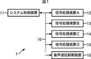
図1は、本発明を適用した情報処理システムの構成例を表している。同図に示されるように、情報処理システム1は、システム制御装置11と、信号処理装置12乃至15が、バス10により相互に接続されている。また、必要に応じて、このバス10には、音声遅延制御装置16も接続される。 FIG. 1 shows a configuration example of an information processing system to which the present invention is applied. As shown in FIG. 1, in the
信号処理装置12乃至15は、必要に応じて、それぞれ信号処理装置A乃至信号処理装置Dとも称する。信号処理装置12乃至15は、それぞれ単独で機能する装置として構成することもできるし、また、それぞれが1つの基板として構成され、1つの装置に装着されることで、全体として1つの装置として機能させるようにすることもできる。 The
図2は、信号処理装置12(信号処理装置A)の機能的構成例を表している。同図に示されるように、信号処理装置12は、本処理部31、通信部32、および装置情報格納部33により構成されている。 FIG. 2 illustrates a functional configuration example of the signal processing device 12 (signal processing device A). As shown in the figure, the
通信部32は、バス10を介してシステム制御装置11の他、他の信号処理装置と通信する。装置情報格納部33は、自分自身の信号処理装置ID、処理内容情報、および入出力信号形式を予め格納している。装置情報格納部33は、例えば、マイクロプロセッサ、RAM(Random Access Memory)、ROM(Read Only Memory)などから構成される。もちろん、RAM、フラッシュROM、その他、制御回路だけの構成でもよい。本処理部31は、信号処理装置12の動作を制御する。 The
図示は省略するが、信号処理装置13乃至15、並びに音声遅延制御装置16も、基本的に、図2に示される場合と同様の構成を有している。 Although illustration is omitted, the
信号処理装置IDは、各信号処理装置を識別するための各信号処理装置に固有の識別番号である。 The signal processing device ID is an identification number unique to each signal processing device for identifying each signal processing device.
処理内容情報は、その信号処理装置が実行可能な処理に関する情報である。図3は、この処理内容情報の例を表している。 The processing content information is information relating to processing that can be executed by the signal processing apparatus. FIG. 3 shows an example of this processing content information.
図3には、外部信号入力a,b、外部信号出力a、解像度創造a、ノイズ除去a,bが例示されている。それぞれの処理IDは、00010,00011,00020,00030,00040,または00041とされている。 FIG. 3 illustrates external signal inputs a and b, external signal output a, resolution creation a, and noise removal a and b. Each processing ID is set to 00001,00011,00020,000,30,040, or 00004.
外部信号入力aは、アナログの外部からの信号を入力する処理を意味する。外部とは、バス10を介さないで入力されることを意味する。外部信号入力bは、外部からデジタルの信号を入力する処理を意味する。外部信号出力aは、外部へデジタル信号を出力する処理を意味する。外部へ信号を出力するとは、バス10を介さずに信号を出力することを意味する。 The external signal input a means processing for inputting an analog external signal. “External” means input without going through the
解像度創造aは、解像度を創造する処理を意味する。ノイズ除去aは、伝送路ノイズを除去する処理を意味し、ノイズ除去bは、符号化ノイズを除去する処理を意味する。 Resolution creation a means a process of creating resolution. Noise removal a means processing for removing transmission line noise, and noise removal b means processing for removing coding noise.
各信号処理装置は、これらの処理内容のうち、自分自身が実行する処理内容を処理内容情報として装置情報格納部33に格納する。 Each signal processing device stores the processing content executed by itself in the device
なお、この他、システム内部の制御に必要最低限の情報と、ユーザインターフェースに利用するための情報などが、処理内容情報として記憶されるようにしてもよい。 In addition, the minimum information necessary for control inside the system, information used for the user interface, and the like may be stored as processing content information.
入出力信号形式は、各信号処理装置が入力または出力可能な信号形式を意味する。図4は、入出力信号形式の例を表している。図4の例においては、525i(60I)の信号形式で入力する信号形式と出力する信号形式が、それぞれ記述されている。前者の信号形式IDは00010、対応処理IDは00010とされ、後者の信号形式IDは00011、対応処理IDは00011とされている。 The input / output signal format means a signal format that can be input or output by each signal processing device. FIG. 4 shows an example of the input / output signal format. In the example of FIG. 4, the signal format to be input and the signal format to be output are described in the signal format of 525i (60I). The former signal format ID is 0010, the corresponding process ID is 00010, the latter signal format ID is 00001, and the corresponding process ID is 00001.
さらに、625i(50I)の入力信号形式が、信号形式ID00020、対応処理ID00010として記述されている。さらに、525p(60P)の入力信号形式が、信号形式ID00030、対応処理ID00030として記述されている。720p(60P)の入力信号形式も、信号形式ID00040、対応処理ID00040として記述されている。 Further, the input signal format of 625i (50I) is described as a signal format ID00020 and a corresponding processing ID00010. Further, an input signal format of 525p (60P) is described as a signal format ID 0030 and a corresponding process ID 00003. The input signal format of 720p (60P) is also described as a signal format ID 0640 and a corresponding processing ID 0640.
なお、信号形式の、例えば「525」の数字は走査線の数を表し、「60I」のうちの数字(60)はフレームの数を表している。また、「I」はインタレース方式を表し、「P」はプログレッシブ(線順次方式)を意味する。 In the signal format, for example, the number “525” represents the number of scanning lines, and the number (60) in “60I” represents the number of frames. “I” represents an interlace system, and “P” represents progressive (line-sequential system).
各信号処理装置は、これらの入出力信号形式のうち、自分自身が有するものを装置情報格納部33に保持する。 Each signal processing apparatus holds in its apparatus
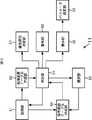
図5は、システム制御装置11の機能的構成例を表している。取得部61は、各信号処理装置12乃至15から、信号処理装置ID、処理内容情報、並びに入出力信号形式を取得する。処理装置テーブル作成部62は、取得部61により取得された信号処理装置IDに基づいて、バス10に接続されている装置を特定するための処理装置テーブルを作成する。判定部63は、処理装置テーブルに変化があるか、外部入力装置があるか、中間装置があるかといった判定処理や、確立していない信号経路があるか、信号経路の数は複数であるかといった判定処理を行う。 FIG. 5 illustrates a functional configuration example of the
信号経路テーブル作成部64は、バス10に接続されている各信号処理装置の信号経路を表す信号経路テーブルを作成し、記憶する。選択部65は、判定部63の判定結果に基づいて各種の選択処理を行う。警告部66は、判定部63の判定結果に基づいて、ユーザに対して各種の警告を行う。優先順位決定部67は、信号経路が複数ある場合において、その優先順位を決定する。表示部68は、決定された信号経路やパラメータの入力画面などの表示を制御する。パラメータ設定部69は、表示部68により表示されたパラメータ入力画面に基づいてパラメータ設定処理を行う。 The signal path
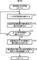
次に、図6と図7のフローチャートを参照して、信号経路テーブル作成処理について説明する。この処理は、例えば、システム制御装置11の電源をオンした直後に実行される。 Next, signal path table creation processing will be described with reference to the flowcharts of FIGS. 6 and 7. This process is executed immediately after the
ステップS1において、取得部61は、信号処理装置IDを取得する処理を実行する。具体的には、取得部61は、バス10を介して、各信号処理装置に対して信号処理装置IDの送信を要求する。各信号処理装置は、その装置情報格納部33に格納されている信号処理装置IDを、バス10を介してシステム制御装置11に通知する。ステップS2において、処理装置テーブル作成部62は、信号処理装置IDを処理装置テーブルに追加する処理を実行する。具体的には、処理装置テーブル作成部62は、取得部61より供給された信号処理装置IDを内部に記憶する処理装置テーブルに追加する。図1の例の場合、信号処理装置A乃至信号処理装置Dが接続されているので、図8に示されるような処理装置テーブルが作成される。図8の例においては、信号処理装置の名称として、信号処理装置A乃至Dと、そのそれぞれの信号処理装置IDとして、00010,00020,00030,または00040が対応して記述されている。 In step S1, the
次に、ステップS3において、判定部63は、処理装置テーブルに変化があるか否かを判定する。すなわち、過去に電源がオンされたときに作成された処理装置テーブルと、今回の電源オン時に作成された処理装置テーブルとが比較され、それらの間に変化がなければ、後述する信号経路テーブルも既に作成済みであるので、処理は終了される。 Next, in step S3, the
これに対して、ステップS3において、判定部63により処理装置テーブルに変化があると判定された場合、ステップS4において、取得部61は、処理内容情報と入出力信号形式を取得する処理を実行する。具体的には、取得部61は、今回作成された処理装置テーブルに、新たに追加された信号処理装置に対して、その処理内容情報と入出力信号形式の送信を要求する。この要求を受けた信号処理装置は、その装置情報格納部33に格納されている自分自身の処理内容情報と入出力信号形式を読み出し、バス10を介してシステム制御装置11に通知する。 On the other hand, when the
取得部61は、この処理内容情報と入出力信号形式を取得すると、これを信号経路テーブル作成部64に供給する。信号経路テーブル作成部64は、ステップS5において、取得部61より供給された処理内容情報と入出力信号形式を信号経路テーブルに追加し、新たな信号経路テーブルを作成する。システム制御装置11の電源が初めてオンされた場合には、前回の処理装置テーブルと信号経路テーブルが存在しないため、接続されている全ての信号処理装置の処理装置テーブルと信号経路テーブルが作成されることになる。図9は、このようにして作成された信号経路テーブルの例を表している。 When acquiring the processing content information and the input / output signal format, the acquiring
図9の例においては、信号処理装置Aは、外部入力aの処理内容を有し、その入力信号形式は、525i(60I),525p(60P)、または1125i(60I)とされ、対応する出力信号形式は、同様に、525i(60I),525p(60P)、または1125i(60I)とされている。すなわち、外部入力aは、入力された信号形式はそのまま出力することを意味する。 In the example of FIG. 9, the signal processing apparatus A has the processing content of the external input a, and the input signal format is 525i (60I), 525p (60P), or 1125i (60I), and the corresponding output Similarly, the signal format is 525i (60I), 525p (60P), or 1125i (60I). That is, the external input a means that the input signal format is output as it is.
信号処理装置Bは、ノイズ除去aの処理内容を有し、その入力信号形式は、525i(60I)または525p(60P)とされ、出力信号形式は、入力信号形式に対応して、それぞれ525i(60I)または525p(60P)とされている。 The signal processing device B has the processing content of noise removal a, and its input signal format is 525i (60I) or 525p (60P), and the output signal format corresponds to the input signal format, respectively 525i ( 60I) or 525p (60P).
すなわち、ノイズ除去aは、525i(60I)または525p(60P)の入力信号形式の入力を、ノイズを除去した後、応する出力信号形式、すなわち525i(60I)または525p(60P)の信号で出力する。 That is, the noise removal a outputs an input signal format of 525i (60I) or 525p (60P) in a corresponding output signal format, that is, a signal of 525i (60I) or 525p (60P) after removing noise. To do.
信号処理装置Cは、処理内容として解像度創造aを有し、その入力信号形式は525i(60I)で、出力信号形式は720p(60P)、または1125i(60I)とされている。 The signal processing apparatus C has resolution creation a as processing contents, and its input signal format is 525i (60I), and its output signal format is 720p (60P) or 1125i (60I).
信号処理装置Cは、525i(60I)の入力信号形式で入力された信号を、その解像度創造を行った後、720p(60P)の出力信号形式または1125i(60I)の出力信号形式で出力する。 The signal processing apparatus C, after creating the resolution of the signal input in the 525i (60I) input signal format, outputs the signal in the 720p (60P) output signal format or the 1125i (60I) output signal format.
信号処理装置Dは、処理内容として外部出力aを有し、その入力信号形式は525i(60I),525p(60P)、または720p(60P)とされ、出力信号形式は、それぞれ入力信号形式に対応して、525i(60I),525p(60P)または720p(60P)とされる。 The signal processing device D has an external output a as processing contents, and its input signal format is 525i (60I), 525p (60P), or 720p (60P), and each output signal format corresponds to the input signal format. Thus, 525i (60I), 525p (60P), or 720p (60P) is obtained.
すなわち、信号処理装置Dは、入力された信号をそのまま外部に出力する機能を有していることになる。 That is, the signal processing device D has a function of outputting the input signal as it is to the outside.
次に、図6のステップS6において、判定部63は、信号経路テーブルに外部入力装置があるか否かを判定する。図9の信号経路テーブルの場合、外部入力装置としての機能を有する信号処理装置Aが存在する。仮に信号経路テーブルに外部入力装置が存在しない場合には、接続処理を実行することができない。そこで、判定部63により、信号経路テーブルに外部入力装置がないと判定された場合、警告部66は、ステップS7において、警告する処理を実行する。具体的には、ユーザに、例えば「外部入力装置がないので接続を行うことができません」といったメッセージを呈示する。 Next, in step S6 of FIG. 6, the
信号経路テーブルに外部入力装置が存在すると判定部63により判定された場合、ステップS8において、選択部65は、外部入力装置を選択する処理を実行する。すなわち、処理装置テーブルに記述されている装置の中から外部入力装置が1つ選択される。例えば、ここで信号処理装置Aが選択される。ステップS9において、信号経路テーブル作成部64は、外部入力装置の出力信号形式に対応する信号を入力信号形式とする他の信号処理装置を外部入力装置の出力装置に配置する。具体的には、ステップS8で選択された信号処理装置Aは、525i(60I),525p(60P)、または1125i(60I)の出力信号形式を有している。これらの出力信号形式のいずれかに対応する入力信号形式を有している装置は、信号処理装置B(525i(60I),525p(60P))、信号処理装置C(525i(60I))、信号処理装置D(525i(60I),525p(60P))である。そこで、図10の信号経路テーブルに示されるように、これらの各信号処理装置B,C,Dが、信号処理装置Aの出力装置として記述される。同様に、信号処理装置B,C,Dの入力装置として、信号処理装置Aが記述される。 If the
これにより、信号処理装置Aの出力が信号処理装置B,CまたはDに供給される信号経路が作成されたことになる。 As a result, a signal path in which the output of the signal processing device A is supplied to the signal processing device B, C, or D is created.
次に、ステップS10において、判定部63は、信号経路テーブルに他の外部入力装置があるか否かを判定する。他の外部入力装置がある場合には、ステップS8に戻り、再び新たな外部入力装置が選択され、その選択された外部入力装置について、ステップS9で信号経路テーブルを作成する処理が実行される。 Next, in step S10, the
しかしながら、図9(図10)の信号経路テーブルの場合、信号処理装置A以外に外部入力装置は存在しない。そこで処理はステップS10からステップS11に進み、ステップS11において、判定部63は、信号経路テーブルに中間装置があるか否かを判定する。中間装置とは、外部入力装置でもなく、また、外部出力装置でもない装置を言う。換言すれば、外部入力装置と外部出力装置との間に配置される装置を意味する。信号経路テーブルに中間装置が存在しない場合には、結局、外部入力装置から入力された処理信号を外部出力装置にそのまま出力するだけのことになるので、実質的には信号経路が作成されたことにならない。そこで、この場合には、ステップS7において、警告部66は、例えば、「接続する装置がありません」といったようなメッセージを表示する。 However, in the case of the signal path table of FIG. 9 (FIG. 10), there is no external input device other than the signal processing device A. Therefore, the process proceeds from step S10 to step S11. In step S11, the
ステップS11において、判定部63により信号経路テーブルに中間装置が存在すると判定された場合、ステップS12において、選択部65は、信号経路テーブルから中間装置を選択する処理を実行する。図9(図10)の信号経路テーブルの例の場合、信号処理装置Bと信号処理装置Cが中間装置である。そこで、ステップS12において、例えば、信号処理装置Bが選択される。ステップS13において、信号経路テーブル作成部64は、中間装置の出力信号形式に対応する信号を入力信号形式とする他の信号処理装置を中間装置の出力装置に配置する。これにより、例えば図11に示されるように、信号処理装置Bの出力装置として、信号処理装置Cと信号処理装置Dが記述され、信号処理装置Cと信号処理装置Dの入力装置として、信号処理装置Bが記述される。 If the
次に、ステップS14において、判定部63は、信号経路テーブルに他の中間装置があるか否かを判定する。図9(図11)の信号経路テーブルの場合、信号処理装置Cも中間装置である。そこで、ステップS12に戻り、選択部65は、信号処理装置Cを中間装置として選択する。そして、ステップS13において、信号経路テーブル作成部64は、図12に示されるように、信号処理装置Cの出力装置として信号処理装置Dを記述し、信号処理装置Dの入力装置として信号処理装置Cを記述する。 Next, in step S14, the
再びステップS14において、判定部63は、信号経路テーブルに他の中間装置があるか否かを判定する。図9(図12)の信号経路テーブルの場合、もはや、他の中間装置は存在しない。そこで、ステップS15において、判定部63は、確立していない信号経路があるか否かを判定する。図12の信号経路テーブルに示されるように、中間装置である信号処理装置Cの上から2番目の経路には出力装置が記述されていない。同様に、上から4番目の経路にも出力装置が記述されていない。このことは、この経路は確立していないことを意味する。そこで、ステップS16において信号経路テーブル作成部64は、確立していない信号経路を削除する処理を実行する。具体的には、図12に示される信号処理装置Cのうちの上から2番目と4番目の経路を削除する。これにより、信号経路テーブルは、図13に示されるようになる。 In step S14 again, the
ステップS15において、確立していない信号経路が存在しないと判定された場合には、ステップS16の処理は、必要がないのでスキップされる。 If it is determined in step S15 that there is no signal path that has not been established, the process of step S16 is skipped because it is not necessary.
その後、ステップS17において、判定部63は、信号経路は複数あるか否かを判定する。信号経路が複数ある場合には、ステップS18において、複数の信号経路の中から1つの信号経路を選択するための優先順位決定処理が実行される。この優先順位決定処理の詳細については、図20または図23のフローチャートを参照して後述する。 Thereafter, in step S17, the
ステップS17において、判定部63により信号経路は複数存在しないと判定された場合には、ステップS18の優先順位決定処理はスキップされる。 In step S17, when the
次に、ステップS19において、表示部68は、信号経路を表示する処理を行う。具体的には、ステップS18またはステップS9,S13,S16で作成された信号経路がモニタ等に表示され、ユーザに提示される。 Next, in step S19, the
その後、ステップS20において、パラメータ設定書部69は、パラメータ設定処理を実行する。このパラメータ設定処理の詳細は、図28のフローチャートを参照して後述するが、これにより選択された信号経路を構成する信号処理装置のパラメータが設定される。 Thereafter, in step S20, the parameter
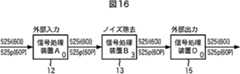
図13の信号経路テーブルに記述されている信号経路を図示すると、図14に示されるようになる。この信号経路は、分解すると、図15乃至図18に示されるように、4つの信号経路を含んでいる。 FIG. 14 shows the signal paths described in the signal path table of FIG. This signal path, when disassembled, includes four signal paths as shown in FIGS.
図15の信号経路では、外部入力装置である信号処理装置Aが、525i(60I)または525p(60P)の入力信号形式で入力された信号をそのままの形式で外部出力装置としての信号処理装置Dに出力し、信号処理装置Dは、その信号そのままの出力信号形式で出力する。すなわち、この場合には、入力された信号がスルーされるだけで、実質的に処理は何も行われないことになる。 In the signal path of FIG. 15, the signal processing device A, which is an external input device, uses a signal input in the 525i (60I) or 525p (60P) input signal format as it is as the signal processing device D as an external output device. The signal processing device D outputs the signal as it is in the output signal format. That is, in this case, the input signal is simply passed through, and virtually no processing is performed.
図16の信号経路には、信号処理装置A,B,Dが、順次配置されている。信号処理装置Aは、525i(60I)または525p(60P)の入力信号形式で入力された信号を、ノイズ除去機能を有する中間装置としての信号処理装置Bに供給する。信号処理装置Bは、525i(60I)または525p(60P)の入力信号形式で入力された信号のノイズを除去し、対応する出力信号形式の出力信号として、外部出力装置としての信号処理装置Dに出力する。信号出力装置Dは、525i(60I)または525p(60P)の入力信号形式で入力された信号を、そのままの形式で出力する。 In the signal path of FIG. 16, signal processing devices A, B, and D are sequentially arranged. The signal processing apparatus A supplies a signal input in an input signal format of 525i (60I) or 525p (60P) to a signal processing apparatus B as an intermediate apparatus having a noise removal function. The signal processing device B removes noise from the signal input in the 525i (60I) or 525p (60P) input signal format, and outputs it to the signal processing device D as an external output device as an output signal in the corresponding output signal format. Output. The signal output device D outputs the signal input in the input signal format of 525i (60I) or 525p (60P) in the format as it is.
図17の信号経路においては、信号処理装置A,C,Dが、順次配置されている。信号処理装置Aは、525i(60I)の入力信号形式で信号を入力し、これを、そのままの形式で中間装置としての信号処理装置Cに供給する。信号処理装置Cは、525i(60I)の入力信号形式で入力された信号に対して解像度創造処理を実行し、720p(60P)の出力信号形式で外部出力装置としての信号処理装置Dに出力する。信号処理装置Dは、720p(60P)の入力信号形式で入力された信号を、そのままの形式で外部の装置に出力する。 In the signal path of FIG. 17, the signal processing devices A, C, and D are sequentially arranged. The signal processing apparatus A inputs a signal in the input signal format of 525i (60I), and supplies this to the signal processing apparatus C as an intermediate apparatus in the same format. The signal processing device C performs resolution creation processing on the signal input in the 525i (60I) input signal format, and outputs it to the signal processing device D as an external output device in the 720p (60P) output signal format. . The signal processing device D outputs a signal input in the 720p (60P) input signal format to an external device in the same format.
図18の信号経路においては、信号処理装置A,B,Dが順次配置されている。外部入力装置としての信号処理装置Aは、525i(60I)の入力信号形式で信号を入力し、そのままの形式で中間装置としての信号処理装置Bに出力する。信号処理装置Bは、525i(60I)の入力信号形式で入力された信号に対してノイズ除去の処理を行い、同一の信号形式で、中間装置としての信号処理装置Cに出力する。 In the signal path of FIG. 18, signal processing devices A, B, and D are sequentially arranged. The signal processing device A as an external input device inputs a signal in an input signal format of 525i (60I) and outputs it as it is to a signal processing device B as an intermediate device. The signal processing device B performs noise removal processing on the signal input in the 525i (60I) input signal format, and outputs the signal to the signal processing device C as an intermediate device in the same signal format.
信号処理装置Cは、525i(60I)の入力信号形式で入力された信号に対して解像度創造処理を行い、720p(60P)の出力信号形式で、外部出力装置としての信号処理装置Dに出力する。信号処理装置Dは、720p(60P)の入力信号形式で入力された信号をそのままの形式で外部装置に出力する。 The signal processing device C performs resolution creation processing on the signal input in the 525i (60I) input signal format, and outputs it to the signal processing device D as an external output device in the 720p (60P) output signal format. . The signal processing device D outputs the signal input in the 720p (60P) input signal format to the external device as it is.
このように、4つの信号経路が存在するため、優先順位決定部67は、ステップS18の優先順位決定処理において、1つの信号経路を決定する処理を行う。このため、優先順位決定部67は、図19に示されるような機能的構成を有している。 As described above, since there are four signal paths, the priority
選択部91は、複数の信号経路の中から1つの信号経路を選択する処理を実行する。重み計算部92は、選択部91により選択された信号経路の重みを計算する。判定部93は、全ての信号経路に対して重み計算処理を実行したか否かを判定し、まだ計算していない信号経路が存在する場合には、選択部91に再び他の信号経路を選択させる。決定部94は、重み計算部92により計算された重みに基づいて、優先順位を決定する。 The
次に、図20のフローチャートを参照して、優先順位決定処理について説明する。ステップS31において、選択部91は、複数の信号経路の中から1つの信号経路を選択する。例えば、図15乃至図18に示される経路の中から、図15に示される信号経路がここで選択される。ステップS32において、重み計算部92は、各信号処理装置の優先順位の重みを加算する。具体的には、この実施の形態の場合、信号処理装置Aには0、信号処理装置Bには3、信号処理装置Cには2、信号処理装置Dには0の重みがそれぞれ予め決められている。この重みも信号処理装置IDとともに、各信号処理装置からシステム制御装置11に供給されている。重み計算部92は、この重みを記録している。図15の信号経路の場合、信号入力装置Aと信号入力装置Dの重みはいずれも0であるため、その加算値は0である。 Next, priority order determination processing will be described with reference to the flowchart of FIG. In step S31, the
次に、ステップS33において、判定部93は、全ての信号経路を選択したか否かを判定する。いまの場合、まだ全ての信号経路を選択していないため、選択部93は、ステップS31において、再び選択部91に他の1つの信号経路を選択させる。これにより、例えば、図16の信号経路が選択される。ステップS32において、重み計算部92は、図16の信号経路の各装置の重みを計算する。この場合、信号処理装置Aの重みは0、信号処理装置Bの重みは3、信号処理装置Dの重みは0であるため、その加算値は3となる。 Next, in step S33, the
以下同様の処理が、順次実行され、図17に示される信号経路は、信号処理装置Aの重みが0、信号処理装置Cの重みが2、信号処理装置Dの重みが0であるため、その加算値は2となる。また、図18に示される信号経路の場合、信号処理装置Aの重みは0、信号処理装置Bの重みは3、信号処理装置Cの重みは2、信号処理装置Dの重みは0であるため、その加算値は5となる。 Thereafter, the same processing is sequentially performed, and the signal path shown in FIG. 17 has a weight of 0 for the signal processing device A, a weight of 2 for the signal processing device C, and a weight of 0 for the signal processing device D. The added value is 2. In the case of the signal path shown in FIG. 18, the weight of the signal processing device A is 0, the weight of the signal processing device B is 3, the weight of the signal processing device C is 2, and the weight of the signal processing device D is 0. The added value is 5.
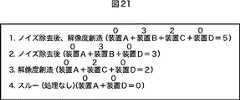
ステップS33において、全ての信号経路を選択したと判定された場合、ステップS34において、決定部94は、加算値の大きさの順番に優先順位を決定する。すなわち、いまの場合、図15乃至図18に示される4つの信号経路の重みの加算値は、順番に図示すると、図21に示されるようになる。図18に示されるノイズ除去後解像度創造処理を実行する信号経路の重みの加算値が5で最も重く、次が、図16に示されるノイズ除去を実行する信号経路の加算値が3で、3番目に重いのが、図17に示される解像度創造処理を実行する加算値が2で、加算値が最も小さいのは、図15に示される信号経路で、その値は0である。 If it is determined in step S33 that all signal paths have been selected, in step S34, the
従って、この場合には、図21に示されるような優先順位となる。そこで、ステップS35において、決定部94は、優先順位が最も高い信号経路を表示する信号経路とする。図21の例の場合、ノイズ除去後解像度創造処理を実行する信号経路が選択される。従って、図7のステップS19の信号経路を表示する処理では、この例の場合、図18に示される信号経路が表示されることになる。 Therefore, in this case, the priorities are as shown in FIG. Therefore, in step S35, the
以上の優先順位決定処理は、各信号処理装置に予め設定されている重みを利用して優先順位を決定するようにしたが、各信号処理装置に想定されている想定信号経路に基づいて重みを決定するようにしてもよい。このようにする場合、優先順位決定部67は、例えば、図22に示されるように構成される。 In the above priority determination processing, the priority is determined using the weight set in advance for each signal processing device. However, the weight is determined based on the assumed signal path assumed for each signal processing device. It may be determined. In this case, the priority
記憶部111は、デフォルトの優先順位を予め記憶する。デフォルト順位設定部112は、記憶部111に記憶されているデフォルト順位を設定する。判定部113は、想定信号経路を有する信号処理装置が存在するか否かを判定する。選択部114は、想定信号経路を有する信号処理装置が存在する場合、その想定信号経路の中から、より上流の信号処理装置を選択する処理を行う。 The
削除部115は、実際に接続されていない信号処理装置が含まれる想定信号経路を削除する処理を実行する。補正部116は、デフォルト順位設定部112により設定されたデフォルトの優先順位を、選択部114で選択された優先順位に基づいて補正する処理を実行する。決定部117は、優先順位が最も高い信号経路を決定する。 The
次に、図23のフローチャートを参照して、想定信号経路に基づく優先順位決定処理について説明する。 Next, with reference to the flowchart of FIG. 23, priority order determination processing based on the assumed signal path will be described.
ステップS51において、デフォルト順位設定部112は、デフォルトの優先順位を設定する。具体的には、記憶部111に予め記憶されているデフォルト順位が、仮の優先順位としてここで設定される。このデフォルトの優先順位としては、例えば、上述した図20の処理により決定される優先順位とすることもできる。このようにした場合、ここで図24に示される優先順位が仮の順位として設定されることになる。 In step S51, the default
すなわち、第1番目がノイズ除去後解像度創造処理を行う信号経路、第2番目がノイズ除去を行う信号経路、第3番目が解像度創造処理を実行する信号経路、第4番目がスルー処理を行う信号経路である。 That is, the first is a signal path for performing a noise creation process after noise removal, the second is a signal path for performing noise removal, the third is a signal path for performing a resolution creation process, and the fourth is a signal for performing a through process. It is a route.
次に、ステップS52において、判定部113は、想定信号経路を有する信号処理装置があるか否かを判定する。すなわち、この実施の形態の場合、各信号処理装置に、その信号処理装置を使用する場合に想定される信号経路の優先順位が予め記憶されている。そして、この信号経路も、信号処理装置IDとともにシステム制御装置11に供給される。例えば、信号処理装置Cに、図25に示されるような想定信号経路が付加されている場合、これがシステム制御装置11に供給される。図25の例の場合、第1番目が外部入力、ノイズ除去、時間解像度創造、解像度創造、外部出力の信号経路であり、第2番目の信号経路が、外部入力、解像度創造、外部出力の信号経路であり、第3番目の信号経路が、外部入力、ノイズ除去、解像度創造、外部出力の信号経路である。 Next, in step S52, the
ステップS53において、選択部114は、より上流の信号処理装置の想定信号経路を選択する。具体的には、ステップS51の処理で、仮に設定された優先順位のうち、最も優先順位の高い信号経路において、最もその信号の流れる上流側の信号処理装置の想定信号経路が選択される。具体的には、ステップS51では、図24に示される優先順位が設定されているため、最もその優先順位の高い第1番目の信号経路での信号処理の順番は、信号処理装置A,B,C,Dの順である。従って、信号処理装置Aが最も上流であり、信号処理装置Dが最も下流である。想定信号経路が信号処理装置Bと信号処理装置Cとに付加されている場合には、より上流側の信号処理装置Bの想定信号経路が選択される。いまの場合、信号処理装置Bには、想定信号経路が付加されていないので、信号処理装置Cの図25に示されるような想定信号経路が選択される。これにより、より最適な信号経路を設定することが可能となる。 In step S <b> 53, the
ステップS54において、判定部113は、接続されていない信号処理装置を含む想定信号経路があるか否かを判定する。すなわち、ステップS53の処理で選択された想定信号経路の中に、実際に接続されている信号処理装置があり、実行できない機能が含まれているか否かが判定される。すなわち、その処理を実行するには、他の信号処理装置を接続しなければできないか否かが判定される。他の信号処理装置を接続しなければ実行できない場合には、その想定信号経路は実行不能であるため、ステップS55において、削除部115は、接続されていない信号処理装置を含む想定信号経路を削除する。図25の例の場合、第1番目の信号経路のうち、時間解像度創造処理は、信号処理装置A乃至Dのいずれも実行することができない機能であり、従って、実行解像度創造処理のための信号処理装置は、接続されていない。そこで、この想定信号経路は削除される。 In step S54, the
ステップS54において、接続されていない信号処理装置を含む想定信号経路が存在しないと判定された場合、削除すべき想定信号経路は存在しないため、ステップS55の処理はスキップされる。 If it is determined in step S54 that there is no assumed signal path including a signal processing apparatus that is not connected, the process in step S55 is skipped because there is no assumed signal path to be deleted.
次に、ステップS56において、補正部116は、デフォルトの優先順位を想定信号経路で補正する処理を実行する。この場合、想定信号経路での優先順位がデフォルトの優先順位より優先される。このため、ステップS51の処理で設定された図24に示される優先順位は、ステップS55で設定された想定信号経路により補正され、図26に示されるような優先順位となる。すなわち、図25では、図24の第3番目の解像度創造が第1番目であり、図24の第1番目のノイズ除去後、解像度創造を行う処理が第2番目の優先順位とされる。このため、図24の第3番目の優先順位が最上位の優先順位とされ、図26に示されるような優先順位となる。 Next, in step S56, the
ステップS57において、決定部117は、優先順位が最も高い信号経路を表示する信号経路とする処理を実行する。具体的には、決定部117は、図26の第1番目の解像度創造処理を実行する信号経路、すなわち、図17の信号経路を表示する信号経路として決定する。 In step S <b> 57, the
従って、この場合には、図7のステップS19において、この図17に示される信号経路が表示されることになる。 Therefore, in this case, the signal path shown in FIG. 17 is displayed in step S19 of FIG.
次に、図7のステップS20におけるパラメータ設定処理の詳細について説明する。このパラメータ設定処理を実行するために、図5のパラメータ設定部69は、例えば、図27に示されるような機能的構成を有している。 Next, details of the parameter setting process in step S20 of FIG. 7 will be described. In order to execute this parameter setting process, the
判定部151は、ユーザより指定されたモードが簡易設定モードであるのか詳細設定モードであるのかを判定する。表示部152は、判定部151により判定されたモードに対応するパラメータ設定入力画面としてのウィンドウを表示する。受け付け部153は、表示部152により表示されたパラメータ入力画面に基づいて、ユーザより入力されたパラメータを受け付ける。設定部154は、受け付け部153により受け付けられたパラメータを設定する処理を実行する。 The
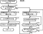
次に、図28のフローチャートを参照して、パラメータ設定処理について説明する。ステップS71において、判定部151は、ユーザからの指令に基づいて、現在設定されているモードは簡易設定モードか否かを判定する。モードが簡易設定モードでない(詳細設定モードである)と判定された場合、ステップS72において、表示部152は、詳細設定ウィンドウをモニタに表示させる。これにより、例えば、図29Aに示されるノイズ除去に関するパラメータ入力画面が表示される。ユーザは、この入力画面に基づいて、ノイズ除去のためのパラメータとして、パラメータN1とパラメータN2を入力する。 Next, parameter setting processing will be described with reference to the flowchart of FIG. In step S71, the
ユーザがパラメータを入力すると、ステップS73において、受け付け部153は、入力されたパラメータを受け付ける。ステップS74において、受け付け部153は、入力が完了したか否かを判定し、まだ完了していない場合には、ステップS73に戻り、再び入力を受け付ける処理を実行する。ステップS74において、入力が完了したと判定された場合、ステップS75において、判定部154は、全ての入力が完了したか否かを判定する。まだ全ての入力が完了していないと判定した場合、判定部154は、表示部152を制御し、ステップS72において、前の表示に替えて、新たなパラメータ入力画面を表示させる。これにより、例えば図29Bに示されるパラメータ入力画面が表示される。このパラメータ入力画面においては、解像度創造処理のためのパラメータとして、パラメータV1とパラメータV2が入力される。 When the user inputs a parameter, in step S73, the receiving
ステップS73において、受け付け部153は、今表示されているパラメータ入力画面からの入力を受け付け、ステップS74において入力が完了したと判定されるまで、受付処理を繰り返す。入力が完了したと判定された場合、ステップS75において、判定部154は、再び全ての入力が完了したか否かを判定する。全ての入力が完了したと判定された場合、ステップS78において、設定部155は、ステップS73で受け付けられたパラメータを設定する処理を実行する。これにより、図29Aと図29Bに示される入力画面で設定されたノイズ除去のためのパラメータN1,N2と、解像度創造処理のためのパラメータV1,V2が設定される。これにより、信号処理装置Bと信号処理装置Cにおいては、それぞれのパラメータを利用して、ノイズ除去または解像度創造処理が実行される。 In step S73, the accepting
ステップS71において、現在のモードが簡易設定モードであると判定された場合、ステップS76において、表示部152は、パラメータ入力画面として簡易設定ウィンドウを表示する。この簡易設定ウィンドウの例が、図30に示されている。図30の例においては、ノイズ除去のためのパラメータとして、パラメータN1だけが、解像度創造処理のためのパラメータとして、パラメータV1だけが、それぞれ入力できるようになっている。すなわち、このモードは簡易設定モードであるため、ユーザは、簡単にパラメータを設定することができるようになされている。換言すれば、この簡易設定モードにおいては、パラメータN2とパラメータV2は、設定部154がユーザより入力されたパラメータN1とパラメータV1に基づいて、最適な値を自動的に決定する。これにより、ユーザは、より微細なパラメータの調整はできないが、より簡易な入力が可能となる。 If it is determined in step S71 that the current mode is the simple setting mode, in step S76, the
ステップS77において受け付け部153は、ステップS76で表示されたウィンドウから入力されたパラメータを受け付け、ステップS78において、設定部154は、ステップS77の処理で受け付けられたパラメータを設定する。 In step S77, the
このように、詳細設定モードの場合には、図29Aに示されるノイズ除去のパラメータの入力が完了した後、そのパラメータ入力画面が切り換えられ、図29Bに示される解像度創造のためのパラメータ入力画面が表示される。これにより、ユーザは、より詳細にパラメータを設定することができる。 As described above, in the detailed setting mode, after the input of the noise removal parameter shown in FIG. 29A is completed, the parameter input screen is switched, and the parameter input screen for creating the resolution shown in FIG. 29B is displayed. Is displayed. Thereby, the user can set parameters in more detail.
これに対して、簡易設定モードにおいては、入力画面は1回しか表示されない。これにより、簡単かつ迅速なパラメータ設定を可能とする。 On the other hand, in the simple setting mode, the input screen is displayed only once. Thereby, simple and quick parameter setting is enabled.
なお、音声遅延制御装置16が接続されている場合、設定された信号経路に基づいて、画像信号の処理時間遅延分と音声信号の処理時間遅延分を同期させる、いわゆるリップシンク処理を行うようにすることもできる。 When the audio
例えば、図15乃至図18に示される信号処理装置A乃至信号処理装置Dのそれぞれの画像信号の処理時間の長さが0,1,2,0と設定されている場合、図15に示される信号経路が設定された場合、音声遅延量を0とし、図16に示される信号経路が設定された場合、音声遅延量を1、図17に示される信号経路が設定された場合、音声遅延量を2とし、図18に示される信号経路が設定された場合、音声遅延量を3とし、それぞれの遅延時間を音声遅延制御装置16により制御するようにしてもよい。 For example, when the length of the processing time of each image signal of the signal processing devices A to D shown in FIGS. 15 to 18 is set to 0, 1, 2, 0, it is shown in FIG. When the signal path is set, the voice delay amount is set to 0, when the signal path shown in FIG. 16 is set, the voice delay amount is set to 1, and when the signal path shown in FIG. 17 is set, the voice delay amount is set. 18 and the signal path shown in FIG. 18 is set, the audio delay amount may be set to 3, and the respective delay times may be controlled by the audio
上述した一連の処理は、ハードウエアにより実行させることもできるし、ソフトウエアにより実行させることもできる。この場合、例えば、システム制御装置11は、図31に示されるようなパーソナルコンピュータにより構成される。 The series of processes described above can be executed by hardware or can be executed by software. In this case, for example, the
図31において、CPU(Central Processing Unit)221は、ROM(Read Only Memory)222に記憶されているプログラム、または記憶部228からRAM(Random Access Memory)223にロードされたプログラムに従って各種の処理を実行する。RAM223にはまた、CPU221が各種の処理を実行する上において必要なデータなども適宜記憶される。 In FIG. 31, a CPU (Central Processing Unit) 221 executes various processes according to a program stored in a ROM (Read Only Memory) 222 or a program loaded from a
CPU221、ROM222、およびRAM223は、バス224を介して相互に接続されている。このバス224にはまた、入出力インタフェース225も接続されている。 The
入出力インタフェース225には、キーボード、マウスなどよりなる入力部226、CRT(Cathode Ray Tube)、LCD(Liquid Crystal display)などよりなるディスプレイ、並びにスピーカなどよりなる出力部227、ハードディスクなどより構成される記憶部228、モデムなどより構成される通信部229が接続されている。通信部229は、インターネットを含むネットワークを介しての通信処理を行う。 The input /
入出力インタフェース225にはまた、必要に応じてドライブ230が接続され、磁気ディスク、光ディスク、光磁気ディスク、或いは半導体メモリなどのリムーバブルメディア231が適宜装着され、それらから読み出されたコンピュータプログラムが、必要に応じて記憶部228にインストールされる。
A
一連の処理をソフトウエアにより実行させる場合には、そのソフトウエアを構成するプログラムが、専用のハードウエアに組み込まれているコンピュータ、または、各種のプログラムをインストールすることで、各種の機能を実行することが可能な、例えば汎用のパーソナルコンピュータなどに、ネットワークや記録媒体からインストールされる。 When a series of processing is executed by software, a program constituting the software executes various functions by installing a computer incorporated in dedicated hardware or various programs. For example, a general-purpose personal computer is installed from a network or a recording medium.
この記録媒体は、図31に示されるように、装置本体とは別に、ユーザにプログラムを提供するために配布される、プログラムが記録されている磁気ディスク(フロッピディスクを含む)、光ディスク(CD-ROM(Compact Disk-Read Only Memory),DVD(Digital Versatile Disk)を含む)、光磁気ディスク(MD(Mini-Disk)を含む)、もしくは半導体メモリなどよりなるリムーバブルメディア231により構成されるだけでなく、装置本体に予め組み込まれた状態でユーザに提供される、プログラムが記録されているROM222や、記憶部228に含まれるハードディスクなどで構成される。 As shown in FIG. 31, this recording medium is distributed to provide a program to the user separately from the main body of the apparatus, and includes a magnetic disk (including a floppy disk) on which the program is recorded, an optical disk (CD- It is not only composed of a
なお、本明細書において、記録媒体に記録されるプログラムを記述するステップは、記載された順序に沿って時系列的に行われる処理はもちろん、必ずしも時系列的に処理されなくとも、並列的あるいは個別に実行される処理をも含むものである。 In the present specification, the step of describing the program recorded on the recording medium is not limited to the processing performed in chronological order according to the described order, but is not necessarily performed in chronological order. It also includes processes that are executed individually.
また、本明細書において、システムとは、複数の装置により構成される装置全体を表すものである。 Further, in this specification, the system represents the entire apparatus constituted by a plurality of apparatuses.
1 情報処理システム, 11 システム制御装置, 12乃至15 信号処理装置, 16 音声遅延制御装置, 31 本処理部, 32 通信部, 33 装置情報格納部, 61 取得部, 62 処理装置テーブル作成部, 63 判定部, 64 信号経路テーブル作成部, 65 選択部, 66 警告部, 67 優先順位決定部, 68 表示部, 69 パラメータ設定部 DESCRIPTION OF
Claims (9)
Translated fromJapanese前記信号処理装置の中から第1の装置として、外部からの処理信号を入力する外部入力装置を選択する選択手段と、
選択された前記第1の装置の出力信号形式に対応する入力信号形式を有する第2の装置を前記信号処理装置の中から選択し、前記第1の装置が出力する処理信号を入力する装置とする信号経路テーブルを作成する作成手段と、
前記信号経路テーブルに作成された前記信号経路の表示を制御する表示手段と
を備え、
前記選択手段は、前記外部入力装置に関する前記信号経路テーブルの作成が完了した後、前記外部入力装置以外の装置であって、かつ、処理信号を外部に出力する外部出力装置以外の装置である中間装置を選択し、
前記作成手段は、前記外部入力装置に関する前記信号経路テーブルの作成が完了した後、前記中間装置を前記第1の装置として前記信号経路テーブルを作成する
ことを特徴とする情報処理装置。Obtaining means for obtaining an input / output signal format from a connected signal processing device;
Selection meansfor selecting anexternal input device for inputting an external processing signal as the first device from among the signal processing devices;
A device that selects a second device having an input signal format corresponding to the selected output signal format of the first device from the signal processing devices and inputs a processing signal output by the first device; Creating means for creating a signal path table to be
Display means for controlling display of the signal path created in the signal path table;
The selecting means is a device other than the external input device after the creation of the signal path table related to the external input device is completed, and an intermediate device other than the external output device that outputs a processing signal to the outside. Select the device
The creation unit creates the signal path table using the intermediate apparatus as the first apparatus after the creation of the signal path table related to the external input device is completed.
An information processing apparatus characterized by that.
ことを特徴とする請求項1に記載の情報処理装置。2. The information according to claim1 , wherein the creation unit deletes, from the signal path table, the signal processing apparatus in which the signal path is not established after the creation of the signal path table related to the intermediate apparatus is completed. Processing equipment.
さらに備えることを特徴とする請求項1に記載の情報処理装置。2. The apparatus according to claim 1, further comprising: a determination unit that determines one signal path having thehighest priority based on a priority when there are a plurality of the signal paths created in the signal path table. Information processing device.
ことを特徴とする請求項3に記載の情報処理装置。The information processing apparatus according to claim3 , wherein the determination unit determines the priority based on a weight added in advance to the signal processing apparatus.
ことを特徴とする請求項3に記載の情報処理装置。The information processing apparatus according to claim3 , wherein the determination unit determines the priority order based on the signal path assumed in the signal processing apparatus.
ことを特徴とする請求項1に記載の情報処理装置。The display means further displays a first parameter input screen for setting in detaila parameter fordesignating a processing type of the signal processing device belonging to the signal path when the first mode is selected; The information processing apparatus according to claim 1,wherein when the second mode is selected, a second parameter input screen for easily setting the parameter is displayed.
選択手段と、
作成手段と、
表示手段と
を備える情報処理装置の情報処理方法において、
前記取得手段が、接続されている信号処理装置から入出力信号形式を取得し、
前記選択手段が、前記信号処理装置の中から第1の装置として、外部からの処理信号を入力する外部入力装置を選択し、
前記作成手段が、選択された前記第1の装置の出力信号形式に対応する入力信号形式を有する第2の装置を前記信号処理装置の中から選択し、前記第1の装置が出力する処理信号を入力する装置とする信号経路テーブルを作成し、
前記表示手段が、前記信号経路テーブルに作成された前記信号経路の表示を制御し、
前記選択手段は、前記外部入力装置に関する前記信号経路テーブルの作成が完了した後、前記外部入力装置以外の装置であって、かつ、処理信号を外部に出力する外部出力装置以外の装置である中間装置を選択し、
前記作成手段は、前記外部入力装置に関する前記信号経路テーブルの作成が完了した後、前記中間装置を前記第1の装置として前記信号経路テーブルを作成する
ステップを含むことを特徴とする情報処理方法。Acquisition means;
A selection means;
Creating means;
Display means and
In an information processing method of an information processing apparatus comprising:
The acquisition means acquires an input / output signal format froma connected signal processing device,
The selection means selectsan external input device for inputting a processing signal from the outside as the first device from the signal processing devices,
The creation means selects a second device having an input signal format corresponding tothe selected output signal format of the first device from the signal processing devices, and a processing signal output by the first devicecreate a signal path table to apparatus forinputting,
The display means controls display of the signal path created in the signal path table;
The selecting means is a device other than the external input device after the creation of the signal path table related to the external input device is completed, and an intermediate device other than the external output device that outputs a processing signal to the outside. Select the device
The creation unit creates the signal path table using the intermediate apparatus as the first apparatus after the creation of the signal path table related to the external input device is completed.
An information processing method comprisingsteps .
前記信号処理装置の中から第1の装置として、外部からの処理信号を入力する外部入力装置を選択し、
選択された前記第1の装置の出力信号形式に対応する入力信号形式を有する第2の装置を前記信号処理装置の中から選択し、前記第1の装置が出力する処理信号を入力する装置とする信号経路テーブルを作成し、
前記信号経路テーブルに作成された前記信号経路の表示を制御し、
前記外部入力装置に関する前記信号経路テーブルの作成が完了した後、前記外部入力装置以外の装置であって、かつ、処理信号を外部に出力する外部出力装置以外の装置である中間装置を選択し、
前記外部入力装置に関する前記信号経路テーブルの作成が完了した後、前記中間装置を前記第1の装置として前記信号経路テーブルを作成する
処理を実行させるためのコンピュータが読み取り可能なプログラムが記録されている記録媒体。Get the input / output signal format from the connected signal processing device,
Select an external input device for inputting a processing signal from the outside as the first device from the signal processing device,
A device that selects a second device having an input signal format corresponding to the selected output signal format of the first device from the signal processing devices and inputs a processing signal output by the first device;create a signal pathtable,
Control the display of the signal path created in the signal path table;
After the creation of the signal path table for the external input device is completed, select an intermediate device that is a device other than the external input device and is a device other than the external output device that outputs the processing signal to the outside,
After the creation of the signal path table related to the external input device is completed, the signal path table is created using the intermediate device as the first device.
A recording medium on which a computer-readable programfor executing processing is recorded.
前記信号処理装置の中から第1の装置として、外部からの処理信号を入力する外部入力装置を選択し、
選択された前記第1の装置の出力信号形式に対応する入力信号形式を有する第2の装置を前記信号処理装置の中から選択し、前記第1の装置が出力する処理信号を入力する装置とする信号経路テーブルを作成し、
前記信号経路テーブルに作成された前記信号経路の表示を制御し、
前記外部入力装置に関する前記信号経路テーブルの作成が完了した後、前記外部入力装置以外の装置であって、かつ、処理信号を外部に出力する外部出力装置以外の装置である中間装置を選択し、
前記外部入力装置に関する前記信号経路テーブルの作成が完了した後、前記中間装置を前記第1の装置として前記信号経路テーブルを作成する
処理をコンピュータに実行させることを特徴とするプログラム。Get the input / output signal format from the connected signal processing device,
Select an external input device for inputting a processing signal from the outside as the first device from the signal processing device,
A device that selects a second device having an input signal format corresponding to the selected output signal format of the first device from the signal processing devices and inputs a processing signal output by the first device;create a signal pathtable,
Control the display of the signal path created in the signal path table;
After the creation of the signal path table for the external input device is completed, select an intermediate device that is a device other than the external input device and is a device other than the external output device that outputs the processing signal to the outside,
After the creation of the signal path table related to the external input device is completed, the signal path table is created using the intermediate device as the first device.
A program that causes a computer to executeprocessing .
Priority Applications (2)
| Application Number | Priority Date | Filing Date | Title |
|---|---|---|---|
| JP2004119009AJP4359836B2 (en) | 2004-04-14 | 2004-04-14 | Information processing apparatus and method, recording medium, and program |
| US11/093,868US20050273657A1 (en) | 2004-04-01 | 2005-03-30 | Information processing apparatus and method, and recording medium and program for controlling the same |
Applications Claiming Priority (1)
| Application Number | Priority Date | Filing Date | Title |
|---|---|---|---|
| JP2004119009AJP4359836B2 (en) | 2004-04-14 | 2004-04-14 | Information processing apparatus and method, recording medium, and program |
Publications (2)
| Publication Number | Publication Date |
|---|---|
| JP2005301803A JP2005301803A (en) | 2005-10-27 |
| JP4359836B2true JP4359836B2 (en) | 2009-11-11 |
Family
ID=35333236
Family Applications (1)
| Application Number | Title | Priority Date | Filing Date |
|---|---|---|---|
| JP2004119009AExpired - Fee RelatedJP4359836B2 (en) | 2004-04-01 | 2004-04-14 | Information processing apparatus and method, recording medium, and program |
Country Status (1)
| Country | Link |
|---|---|
| JP (1) | JP4359836B2 (en) |
- 2004
- 2004-04-14JPJP2004119009Apatent/JP4359836B2/ennot_activeExpired - Fee Related
Also Published As
| Publication number | Publication date |
|---|---|
| JP2005301803A (en) | 2005-10-27 |
Similar Documents
| Publication | Publication Date | Title |
|---|---|---|
| JP4525760B2 (en) | Information processing apparatus and information providing method | |
| CN101377917B (en) | Display apparatus | |
| JP2005049837A (en) | Apparatus and method for processing multiple video input signals in a display device | |
| KR101486254B1 (en) | Method for setting frame rate conversion and display apparatus applying the same | |
| EP1881710A1 (en) | Apparatus and method for inspection of electronic devices | |
| US20110234910A1 (en) | Resolution changing device, resolution changing method, and resolution changing program | |
| JP4795906B2 (en) | Video display device and multi-screen display method | |
| JP3797360B2 (en) | AV system, amplification apparatus, content reproduction apparatus, amplification apparatus, and operation program for content reproduction apparatus | |
| US8600946B2 (en) | Content reproducing system and content reproducing method | |
| JP4359836B2 (en) | Information processing apparatus and method, recording medium, and program | |
| US8116594B2 (en) | Image processing apparatus, image processing method, and program | |
| JP2010048974A (en) | Image display, its control method and program, and recording medium | |
| CN100576928C (en) | Image display device and method | |
| JP2007312183A (en) | Image display apparatus | |
| JP2004229085A (en) | Control system, information processor and processing method, apparatus controller and controlling method, recording medium, and program | |
| US20100271386A1 (en) | Method for setting display apparatus and display apparatus using the same | |
| US9253441B2 (en) | Conference system, program and conference method | |
| CN102577424A (en) | Video outputting apparatus, video outputting method and program | |
| JPWO2007119718A1 (en) | Video signal processing apparatus and video signal processing method | |
| US20050273657A1 (en) | Information processing apparatus and method, and recording medium and program for controlling the same | |
| JP2014123891A (en) | Video processing apparatus, video processing method and video processing program | |
| JP2005292876A (en) | Image display system | |
| JP7371658B2 (en) | Video output device | |
| JP2010213129A (en) | Television conference apparatus, television conference system, television conference control method, and program for television conference apparatus | |
| JP2007034553A (en) | Information processing device |
Legal Events
| Date | Code | Title | Description |
|---|---|---|---|
| A621 | Written request for application examination | Free format text:JAPANESE INTERMEDIATE CODE: A621 Effective date:20070305 | |
| A977 | Report on retrieval | Free format text:JAPANESE INTERMEDIATE CODE: A971007 Effective date:20090417 | |
| A131 | Notification of reasons for refusal | Free format text:JAPANESE INTERMEDIATE CODE: A131 Effective date:20090428 | |
| A521 | Written amendment | Free format text:JAPANESE INTERMEDIATE CODE: A523 Effective date:20090626 | |
| TRDD | Decision of grant or rejection written | ||
| A01 | Written decision to grant a patent or to grant a registration (utility model) | Free format text:JAPANESE INTERMEDIATE CODE: A01 Effective date:20090716 | |
| A01 | Written decision to grant a patent or to grant a registration (utility model) | Free format text:JAPANESE INTERMEDIATE CODE: A01 | |
| A61 | First payment of annual fees (during grant procedure) | Free format text:JAPANESE INTERMEDIATE CODE: A61 Effective date:20090729 | |
| FPAY | Renewal fee payment (event date is renewal date of database) | Free format text:PAYMENT UNTIL: 20120821 Year of fee payment:3 | |
| FPAY | Renewal fee payment (event date is renewal date of database) | Free format text:PAYMENT UNTIL: 20130821 Year of fee payment:4 | |
| R250 | Receipt of annual fees | Free format text:JAPANESE INTERMEDIATE CODE: R250 | |
| R250 | Receipt of annual fees | Free format text:JAPANESE INTERMEDIATE CODE: R250 | |
| R250 | Receipt of annual fees | Free format text:JAPANESE INTERMEDIATE CODE: R250 | |
| LAPS | Cancellation because of no payment of annual fees |