JP4359239B2 - Flight equipment - Google Patents
Flight equipmentDownload PDFInfo
- Publication number
- JP4359239B2 JP4359239B2JP2004540701AJP2004540701AJP4359239B2JP 4359239 B2JP4359239 B2JP 4359239B2JP 2004540701 AJP2004540701 AJP 2004540701AJP 2004540701 AJP2004540701 AJP 2004540701AJP 4359239 B2JP4359239 B2JP 4359239B2
- Authority
- JP
- Japan
- Prior art keywords
- flight
- unit
- flying
- levitation
- flying device
- Prior art date
- Legal status (The legal status is an assumption and is not a legal conclusion. Google has not performed a legal analysis and makes no representation as to the accuracy of the status listed.)
- Expired - Fee Related
Links
Images


Classifications
- A—HUMAN NECESSITIES
- A63—SPORTS; GAMES; AMUSEMENTS
- A63G—MERRY-GO-ROUNDS; SWINGS; ROCKING-HORSES; CHUTES; SWITCHBACKS; SIMILAR DEVICES FOR PUBLIC AMUSEMENT
- A63G31/00—Amusement arrangements
- B—PERFORMING OPERATIONS; TRANSPORTING
- B64—AIRCRAFT; AVIATION; COSMONAUTICS
- B64C—AEROPLANES; HELICOPTERS
- B64C39/00—Aircraft not otherwise provided for
- B64C39/001—Flying saucers
Landscapes
- Engineering & Computer Science (AREA)
- Aviation & Aerospace Engineering (AREA)
- Toys (AREA)
- Adornments (AREA)
- Transition And Organic Metals Composition Catalysts For Addition Polymerization (AREA)
- Structure Of Belt Conveyors (AREA)
- Catching Or Destruction (AREA)
- Aiming, Guidance, Guns With A Light Source, Armor, Camouflage, And Targets (AREA)
- Physical Deposition Of Substances That Are Components Of Semiconductor Devices (AREA)
- Surgical Instruments (AREA)
- Separation By Low-Temperature Treatments (AREA)
- Burglar Alarm Systems (AREA)
- Details Of Garments (AREA)
Abstract
Description
Translated fromJapanese参加者に飛翔または飛行の感覚を与える遊園地の乗り物は、カーニバルの呼び物として知られている。しかし、既知の飛行装置は、参加者または利用者がそのような遊園地の乗り物を利用する間に積極的に関与する機会が無いように構成されている。それどころか、参加者は、強制的に管理されて例えばローラコースタ、バーティカルコラム(vertical column)、またはロッド(rod)のようなレールに乗って、決められた経路を辿る座席に着座せざるを得ない。したがって、参加者は乗ることしかできず、イベントの経路を自分で決定することはできない。彼は、軌道経路または飛翔プロセスに積極的に影響を及ぼすことができない。 Amusement park rides that give participants a sense of flight or flight are known as carnival features. However, known flight devices are configured such that participants or users do not have the opportunity to be actively involved while using such amusement park vehicles. On the contrary, participants are forced to sit on a seat that follows a predetermined path on a rail such as a roller coaster, a vertical column, or a rod. . Therefore, participants can only ride and cannot determine the event route themselves. He cannot positively affect the trajectory path or flight process.
本発明によって解決しようとする問題は、参加者が飛行または飛翔経験に積極的に参加することを可能にする飛行装置を利用可能にすることである。これは、遊園地の装置だけでなく、特に飛行装置を熟達することができるようにするために不可欠の身体的および知的能力を訓練するための装置をも含む。 The problem to be solved by the present invention is to make available a flying device that allows participants to actively participate in the flight or flight experience. This includes not only amusement park equipment, but especially equipment for training the physical and intellectual abilities essential to be able to master the flying equipment.
この問題を解決するために、請求項1の特徴を持つ飛行装置を提案する。 In order to solve this problem, a flight device having the features of claim 1 is proposed.
したがって、飛行装置はホールと、好ましくは一人、しかし場合によっては二人またはそれ以上の人間を収容することができ、垂直方向に離陸することができ、かつ次いでホール中を自由に飛行することのできる、最小限一台の自由飛行ユニットとを含む。 Thus, the flying device can accommodate a hole and preferably one, but possibly two or more people, can take off vertically and then fly freely through the hole. Includes at least one free flight unit.
このホールは、飛行ユニットが飛行中にホールから出て行くのをホールの境界が防止するように設計される。これは、ホールに閉鎖壁および閉鎖天井を設けることによって実現することができる。しかし、境界を隙間無く閉鎖することが絶対に必要というわけではない。境界は、ホールが言わば飛行ユニットのためのケージを形成するように、線格子によって画定することもできる。境界を機械的手段によって画定する必要さえ無い。飛行ユニットが極限された領域から出るのを防止するために、遠隔制御を使用することさえできる。したがって、例えばこの型の垂直境界に接近したときに、飛行ユニットを強制的に脇に逸らすか下降させることができる。 The hole is designed such that the hole boundary prevents the flight unit from exiting the hole during flight. This can be achieved by providing a closed wall and a closed ceiling in the hall. However, it is not absolutely necessary to close the boundaries without any gaps. The boundary can also be defined by a line grid so that the holes form a cage for the flight unit. There is even no need to define the boundary by mechanical means. Remote control can even be used to prevent the flight unit from exiting the limited area. Thus, for example, when approaching this type of vertical boundary, the flight unit can be forced to aside or lowered.
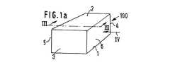
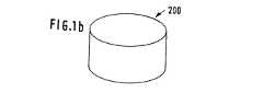
用語「ホール」は、それらが自由飛行ユニットを適切に収容することができる限りにおいて、非常に多様な幾何学的形状の構造を含むつもりである。最も単純で経済的に最も有利な形状は、全ての側面が凸面の構造のそれであり(請求項2)、特に平坦な矩形の側面を持つ箱形の形状の構造のそれである(請求項3)が、平坦でない境界領域、例えば円形の直立境界領域(請求項4)も同様に可能である。 The term “hole” is intended to encompass structures of a great variety of geometric shapes as long as they can properly accommodate a free flight unit. The simplest and most economically advantageous shape is that of a convex structure on all sides (Claim 2), in particular that of a box-shaped structure with flat rectangular sides (Claim 3). However, non-flat boundary regions, for example circular upright boundary regions (claim 4), are possible as well.
構造は全側面が凸面である必要は無い。考えている一つの可能性は、飛行トンネル設計のそれであり(請求項5)、特に、飛行ユニットが閉じた経路内を飛行することができる、自己循環飛行トンネルを持つものである(請求項6)。 The structure need not be convex on all sides. One possibility considered is that of a flight tunnel design (Claim 5), in particular having a self-circulating flight tunnel in which the flight unit can fly in a closed path (Claim 6). ).
請求項7によると、異なる型の多数のホールを組み合わせることも可能である。 According to claim 7, it is also possible to combine a number of different types of holes.
自由飛行の感覚が充分に明瞭になることを確実にするために、飛行ユニットが充分に移動でき、境界に接近するのが早すぎないように、飛行ユニットおよびホールは、相互に対する特定のサイズ比を持たなければならない。例えば、箱形の形状のホールは、一台の飛行ユニットだけの20倍または30倍の長さおよび高さとなるように寸法を決定すべきである。ホールの水平方向の寸法はしばしば、経済的に実現可能なサイズによってだけでなく、遊園地または同様に施設でそのようなホールに利用可能な空間によっても制限される。 In order to ensure that the sense of free flight is sufficiently clear, the flight unit and the hole have a specific size ratio relative to each other so that the flight unit can move sufficiently and not approach the boundary too quickly. Must have. For example, a box-shaped hole should be sized to be 20 or 30 times as long and high as a single flying unit. The horizontal dimensions of the halls are often limited not only by the size that is economically feasible, but also by the space available for such holes at amusement parks or similar facilities.
飛行ユニットは主として、一人の人間を収容するように設計される。実務的に実現可能なホールに対し正しいサイズ比を維持するために、飛行ユニットは過度に大きくすべきではない。つまり、それらは小型飛行機のサイズを持つべきではないのである。この型の飛行ユニットは先行技術から公知である。したがって、例えば、ロサンゼルスのオリンピック競技の開会式中に、ロケット動力式飛行ユニットを備えた飛行士がスタジアム内に浮揚して入場した。そのような飛行ユニットが商業的に実現されるのがいかに近いかは、週刊誌「WELT am SONNTAG」第33号2002年8月18日に発表された「Push the button and lift off」と題する記事から明らかである。 The flight unit is primarily designed to accommodate a single person. In order to maintain the correct size ratio for a practically feasible hole, the flying unit should not be overly large. That is, they should not have the size of a small airplane. This type of flight unit is known from the prior art. Thus, for example, during the opening ceremony of the Los Angeles Olympic Games, an aviator with a rocket powered flight unit floated and entered the stadium. An article titled “Push the button and lift off”, published on August 18, 2002, weekly magazine “WELT am SONNTAG” No. 33, will tell you how closely such a flight unit will be commercially realized. It is clear from
本発明は、乗ることを営業目的とする遊園地またはカーニバル用の呼び物としてだけでなく、ゴーカートトラックのそれと同様の永久固定設備としても適している。さらに、本発明は遊興または娯楽的価値を持つだけでなく、スポーツまたは職業目的に関係する型の飛行ユニットによる飛行訓練用の道具としても使用することができる。 The present invention is suitable not only as an amusement park or carnival feature for business purposes, but also as a permanent fixing facility similar to that of go-kart trucks. Furthermore, the present invention not only has entertainment or entertainment value, but can also be used as a flight training tool with flight units of the type related to sports or professional purposes.
飛行ユニットは、中心に人間用の空間が設けられ、かつ浮揚ユニット組立体をも有する、プラットフォーム付きの飛行円盤の形に設計することができる(請求項8)。そのようなプラットフォームは、充分に強力な浮揚ユニット組立体を収容することができるように、約3〜5mの直径を持つことができる。 The flight unit can be designed in the form of a flight disk with a platform, which is provided with a human space in the center and also has a levitation unit assembly (claim 8). Such a platform can have a diameter of about 3-5 m so that it can accommodate a sufficiently strong levitation unit assembly.
請求項9によると、浮揚ユニット組立体は、中心の周りに分散され、中心の周りに均等に分散された浮揚効果を起動することのできる、複数の別個の浮揚ユニットを含むことができる。 According to claim 9, the levitation unit assembly can comprise a plurality of separate levitation units that are distributed around the center and can activate a levitation effect distributed evenly around the center.
均等な浮揚効果は、プラットフォームを水平面内に保持するのに必要である。均等な浮揚効果は、適切な制御によって達成される。 A uniform levitation effect is necessary to keep the platform in a horizontal plane. An even levitation effect is achieved by appropriate control.
請求項10に係る本発明の好適な実施例では、浮揚ユニットは、動作中に垂直方向に下向きに動作するブロワであり、それは、請求項11に係る実施例では、例えば請求項12に係る駆動用の電力がホール内の検出ループによって供給されるように、電気的に駆動することができる。 In a preferred embodiment of the invention according to
浮揚ユニットを駆動するために、請求項13に係る代替実施例は、燃料燃焼モータが含まれる、プラットフォーム上に配置されるようにする。請求項14によると、別の代替例は、浮揚ユニットがロケットブース他の形で設計される。 In order to drive the levitation unit, an alternative embodiment according to
請求項15に係る本発明の重要な特長は、ホール内の位置をいつでも決定することができるように、少なくとも一台の飛行ユニットが位置検出装置を持つことである。 An important feature of the present invention according to claim 15 is that at least one flight unit has a position detection device so that the position in the hall can be determined at any time.
これは、飛行ユニットの他の飛行ユニッまたはホールの境界との衝突をその設計に関係なく回避するため、または必要ならば特定の飛行ユニットを地上に戻すことができるようにするために(請求項17)、飛行ユニットを遠隔制御装置によって制御できる(請求項16)ことを確実にするための前提条件である。 This is to avoid collisions with other flight units or hole boundaries of the flight unit regardless of its design, or to allow a particular flight unit to be returned to the ground if necessary (claims) 17) A prerequisite for ensuring that the flight unit can be controlled by a remote control device (claim 16).
請求項18によると、ホールは最小限二つのゾーンを含むことができ、飛行ユニットによる飛行は、一つのゾーンまたは特定のゾーンに、例えば初心者を地面の高さに近い低域ゾーンに、制限することができる。 According to claim 18, the hole can comprise a minimum of two zones, and flight by a flight unit limits a beginner to a single zone or a specific zone, for example, a beginner to a low zone close to the ground level. be able to.
請求項19によると、衝突の危険性を無くすために、少なくとも一台の飛行ユニットが、遠隔制御装置に接続された距離センサを装備することが推奨される。 According to claim 19, in order to eliminate the risk of collision, it is recommended that at least one flight unit is equipped with a distance sensor connected to the remote control device.
図面に、本発明に係る飛行ユニットの実施例を図式的表現として示す。 In the drawing, an embodiment of a flight unit according to the present invention is shown as a schematic representation.
図1aでその全体を100で示すホールは、地面1、天井面2、二つの短側面3および4、ならびに二つの長側面5および6を持つ箱形の形状を有する。面2ないし6は、閉鎖壁として、したがって前記ホール内を飛行する飛行ユニット10(図2)がホール100から出ること防止するように、あるいは、飛行ユニット10の制御と関係する「電子壁」として、前記飛行ユニットが箱形の空間から出るのを防止するように、設計可能な境界を形成する。 The hole, generally designated 100 in FIG. 1 a, has a box-like shape with a ground 1, a
箱形の形状は単なる一つの具体的な実施例にすぎない。図1bは、直立円筒形断面の形状を有する代替的構成のホール200を示す。図5は、飛行トンネル組立体40の形態に設計されたホール300を示す。 The box shape is merely one specific embodiment. FIG. 1b shows an alternative configuration of a
図2は、この特定の実施例では飛行円盤の形に設計され、円形断面のプラットフォーム7を含む単一の飛行ユニット10を示し、プラットフォームの中心には、プレキシグラスのような透明な材料から作られたドーム8が配置され、該ドームは、飛行ユニット10の動作中に人間を収容する。ドーム8の全周囲の円形領域に均等に分散されているのは、矢印12として示す浮揚エアジェットをそこから放出する、下方に向けられたノズル11付きの浮揚ブロワ9の形の九個の浮揚ユニット10’である。適切な自動制御によって、浮揚ブロワ9の浮揚効果が周囲全体に均等に分散されることを確実にすることができるので、飛行中、プラットフォーム7は実質的に水平に維持される。プラットフォーム7が約3mの直径を持つ場合、図示した組立体では、浮揚させかつドーム8内の少なくとも一人の人間を飛行させるのに充分な動力を持つ浮揚ブロワ9を収容することが可能である。プラットフォーム7の円形断面および九個の浮揚ブロワ9の個数は実施例の特徴にすぎず、必須ではない。 FIG. 2 shows a
ドーム8内の人間は、ブロワ9の動力出力およびしたがって飛行ユニットの上昇および下降を制御するために、図2には線で示す手動操作制御装置13を利用することができる。人間はまた、浮揚ブロワ9を適切に操ることによって、あるいは水平方向に効果的な追加ノズル(図示せず)によって、進行の方向を決定することもできる。 A person in the
飛行ユニット10の浮揚ユニット10’が浮揚ブロワ9である場合、ホール100、200、300内の飛行ユニット10の自由移動性を維持するために、これらの浮揚ブロワは、ホール100、200、300内の適切な検出ループによって供給される電流により、電気的に駆動することができる。 When the
しかし、浮揚ブロワ9は燃料燃焼モータによって駆動することもでき、それにより構造容積が低減される。また、浮揚ブロワ9の代わりに、ある種のロケットブースタを使用することも可能である。 However, the levitation blower 9 can also be driven by a fuel combustion motor, which reduces the structural volume. It is also possible to use some kind of rocket booster instead of the levitation blower 9.
飛行ユニット10の技術的設計の詳細は、単なる実施例として意図されている。重要なものは、図3でホール100について示唆するように、そのような飛行ユニット10にホール100、200、300中を自由に飛行させる概念である。 Details of the technical design of the
ホール100の自由内部空間20内で、幾つかの飛行ユニット10が自由に飛び回ることができる。図3および4では、飛行ユニット10は、図2におけるそれらの表現とは対照的に、簡素化された形で示される。 Within the free internal space 20 of the
ホール100は、飛行する人間が外部を眺望することができ、したがってより優れた飛行感覚をもたらすように、例えば金属線格子から作成することのできる、図1aに示した境界を有する。 The
内部では、ホール100は追加の境界21、22によって三つのゾーン23、24、25に分割される。最下ゾーン23は地面に近く、初心者用に意図されている。各飛行ユニット10は、さまざまな飛行ユニット10を識別して意図されたゾーン23、24、または25内の存在を監視することのできる遠隔制御装置26と関係する位置検出装置を有する。許可を与えられたゾーンの境界を越えた場合、あるいは技術的問題が発生した場合、飛行ユニットは、手動制御装置13(図2)より優先する遠隔制御装置26によって地上に戻すことができる。 Inside, the
遠隔制御装置26を介しての制御に加えて、他の飛行ユニット10またはホールの境界3、4、5、6との衝突を回避するために、距離センサ27(図2)を個々の飛行ユニットに配置することができる。 In addition to control via
ホール100の内部20のゾーン23、24、25を相互に分離する境界21、22は「電子壁」とすることができる。しかし、境界21、22が線格子壁の形の機械的境界である場合、ゾーン24、25へのアクセスは、飛行ユニット10を高位のゾーン24、25の一つに移送しそれを所望のゾーンに配置する、エレベータ28によって達成される。しかし、最初に飛行ユニット10をケーブルによって高位ゾーン24、25まで吊り上げ、関係する飛行ユニットが飛行状態になってからようやく接続を解除することも可能である。そのようなケーブル接続は、離陸段階中に飛行ユニット10を固定し、必要な浮揚動力が得られない場合に墜落を回避することを可能にする。 The
ホール100、200は全側面に凸形の形状を有するが、図5の「ホール」300は、飛行トンネル30の組立体40を含むものである。飛行トンネル30は管状構造であり、その壁は、ホール100のそれと同様の閉鎖された物理的境界によって、例えば線格子またはプラスチックパネルによって、形成することができる。しかし、飛行トンネル30に「電子壁」を使用することも可能である。飛行トンネル30の内部断面は圧倒的に凸状である、飛行ユニット10が障害無く飛行することを可能にする大きさである。境界との衝突を回避するために、飛行トンネル30の内径は、全方向に飛行ユニット10の直径の約5倍ないし20倍の大きさとすべきである。 The
飛行トンネルの最も単純な実施形態は、例えば比較的大きい箱形ホール100の内側で、またはそのようなホール100から別のそのようなホールへ、直線経路を横断飛行することのできる、直線状の水平飛行トンネルである。 The simplest embodiment of a flight tunnel is a straight line that can fly across a straight path, for example, inside a relatively large box-shaped
次の段階は、飛行ユニット10が閉じた自己循環経路を辿ることを可能にする、リングの形の飛行トンネルである。 The next step is a ring shaped flight tunnel that allows the
図5は、上向きの傾斜をも含み、かつ広大かつ非常に多様な経路での進行を可能にする、かなり複雑な飛行トンネル組立体40を示す。ゾーン31では、飛行トンネル30の三つのセグメントが順に重なった幾つかのレベルで運用される。ゾーン32では、飛行トンネル30は螺旋状経路を形成し、そこから飛行トンネル30は一種のドーム33になり、全側面が凸状の「ホール」を形成する。ゾーン34では、飛行トンネル30は約45度のかなり上向きの傾斜を取る。 FIG. 5 shows a fairly complex
飛行トンネル組立体40は、門様支持構造35によって支持される。それは空間的に比較的大きいが、飛行トンネル組立体40は境界機能を持つだけであり、それ自体の重量以外は何も支持する必要が無いので、容易に実現することができる。 The
1 地面
2 天井面
3 側面
4 側面
5 側面
6 側面
7 プラットフォーム
8 ドーム浮揚ユニット
9 浮揚ブロワ
10 飛行ユニット
10’ 浮揚ユニット
11 ノズル
12 浮揚エアジェット
13 制御装置
23 ゾーン
24 ゾーン
25 ゾーン
26 制御装置
27 距離センサ
28 エレベータ
30 飛行トンネル
31 ゾーン
32 ゾーン
33 ドーム
34 ゾーン
35 支持構造
40 飛行トンネル組立体
100 ホール
200 ホール
300 ホールDESCRIPTION OF SYMBOLS 1
Claims (21)
Translated fromJapanese前記手動操作制御装置(13)とは別に前記飛行ユニット(10)を制御するための遠隔制御装置(26)と、
を備えた飛行装置であって、
前記飛行ユニット(10)が前記ゾーン(23〜25)の境界(2、3、4、5、6、21、22)を越えようとしたときには、前記遠隔制御装置(26)が、前記手動操作制御装置(13)より優先して前記飛行ユニット(10)を制御することを特徴とする飛行装置。It can take offvertically, even withoutleast holes (100,200, 300) freely in thezone (23-25) defined by the boundary (2,3,4,5,6,21,22) in At least one humanKi de beaccommodated, and the flightunit with a manually operated control device (13) for manual operation by the humanbeing (10) in order to flyto,
A remote control device (26) for controlling the flight unit (10) separately from the manual operation control device (13);
A flying device comprising:
When the flight unit (10) tries to cross the boundary (2, 3, 4, 5, 6, 21, 22) of the zone (23-25), the remote control device (26) A flying device characterizedin that theflying unit (10) is controlled in preference to the control device (13) .
Applications Claiming Priority (2)
| Application Number | Priority Date | Filing Date | Title |
|---|---|---|---|
| DE10245351ADE10245351A1 (en) | 2002-09-27 | 2002-09-27 | flight equipment |
| PCT/EP2003/010659WO2004030783A2 (en) | 2002-09-27 | 2003-09-25 | Flying device |
Publications (2)
| Publication Number | Publication Date |
|---|---|
| JP2006515542A JP2006515542A (en) | 2006-06-01 |
| JP4359239B2true JP4359239B2 (en) | 2009-11-04 |
Family
ID=32049168
Family Applications (1)
| Application Number | Title | Priority Date | Filing Date |
|---|---|---|---|
| JP2004540701AExpired - Fee RelatedJP4359239B2 (en) | 2002-09-27 | 2003-09-25 | Flight equipment |
Country Status (10)
| Country | Link |
|---|---|
| US (2) | US7465236B2 (en) |
| EP (1) | EP1549405B1 (en) |
| JP (1) | JP4359239B2 (en) |
| CN (1) | CN100368044C (en) |
| AT (1) | ATE413217T1 (en) |
| AU (1) | AU2003267408A1 (en) |
| DE (2) | DE10245351A1 (en) |
| ES (1) | ES2316793T3 (en) |
| RU (2) | RU2005112724A (en) |
| WO (1) | WO2004030783A2 (en) |
Families Citing this family (48)
| Publication number | Priority date | Publication date | Assignee | Title |
|---|---|---|---|---|
| GB2426150B (en)* | 2005-05-12 | 2007-09-19 | Roke Manor Research | A method of controlling communication |
| CN103157284A (en)* | 2011-12-15 | 2013-06-19 | 渠仁书 | Recreation facility device |
| WO2015000028A1 (en)* | 2013-07-01 | 2015-01-08 | Entecho Pty Ltd | An aerodynamic lifting device |
| DE102013108206A1 (en)* | 2013-07-31 | 2015-02-26 | E-Volo Gmbh | Aircraft, in particular multicopters and use of such, in particular for a flight ride |
| US9550566B2 (en)* | 2015-05-27 | 2017-01-24 | John Francis Henning, JR. | Disc-shaped turbo-jet aircraft |
| DE102017000087A1 (en) | 2016-02-13 | 2017-08-17 | Volker Naumann | Aircraft for passenger transport |
| US10214285B2 (en) | 2016-07-01 | 2019-02-26 | Bell Helicopter Textron Inc. | Aircraft having autonomous and remote flight control capabilities |
| US10011351B2 (en)* | 2016-07-01 | 2018-07-03 | Bell Helicopter Textron Inc. | Passenger pod assembly transportation system |
| US10870487B2 (en) | 2016-07-01 | 2020-12-22 | Bell Textron Inc. | Logistics support aircraft having a minimal drag configuration |
| US11104446B2 (en) | 2016-07-01 | 2021-08-31 | Textron Innovations Inc. | Line replaceable propulsion assemblies for aircraft |
| US10315761B2 (en) | 2016-07-01 | 2019-06-11 | Bell Helicopter Textron Inc. | Aircraft propulsion assembly |
| US10981661B2 (en) | 2016-07-01 | 2021-04-20 | Textron Innovations Inc. | Aircraft having multiple independent yaw authority mechanisms |
| US10633087B2 (en) | 2016-07-01 | 2020-04-28 | Textron Innovations Inc. | Aircraft having hover stability in inclined flight attitudes |
| US11142311B2 (en) | 2016-07-01 | 2021-10-12 | Textron Innovations Inc. | VTOL aircraft for external load operations |
| US9963228B2 (en) | 2016-07-01 | 2018-05-08 | Bell Helicopter Textron Inc. | Aircraft with selectively attachable passenger pod assembly |
| US11608173B2 (en) | 2016-07-01 | 2023-03-21 | Textron Innovations Inc. | Aerial delivery systems using unmanned aircraft |
| US10183746B2 (en) | 2016-07-01 | 2019-01-22 | Bell Helicopter Textron Inc. | Aircraft with independently controllable propulsion assemblies |
| US11124289B2 (en) | 2016-07-01 | 2021-09-21 | Textron Innovations Inc. | Prioritizing use of flight attitude controls of aircraft |
| US10737765B2 (en) | 2016-07-01 | 2020-08-11 | Textron Innovations Inc. | Aircraft having single-axis gimbal mounted propulsion systems |
| US10604249B2 (en) | 2016-07-01 | 2020-03-31 | Textron Innovations Inc. | Man portable aircraft system for rapid in-situ assembly |
| US10737778B2 (en) | 2016-07-01 | 2020-08-11 | Textron Innovations Inc. | Two-axis gimbal mounted propulsion systems for aircraft |
| US10625853B2 (en) | 2016-07-01 | 2020-04-21 | Textron Innovations Inc. | Automated configuration of mission specific aircraft |
| US11084579B2 (en) | 2016-07-01 | 2021-08-10 | Textron Innovations Inc. | Convertible biplane aircraft for capturing drones |
| US10220944B2 (en) | 2016-07-01 | 2019-03-05 | Bell Helicopter Textron Inc. | Aircraft having manned and unmanned flight modes |
| US10597164B2 (en) | 2016-07-01 | 2020-03-24 | Textron Innovations Inc. | Aircraft having redundant directional control |
| US10501193B2 (en) | 2016-07-01 | 2019-12-10 | Textron Innovations Inc. | Aircraft having a versatile propulsion system |
| US10232950B2 (en) | 2016-07-01 | 2019-03-19 | Bell Helicopter Textron Inc. | Aircraft having a fault tolerant distributed propulsion system |
| US10227133B2 (en) | 2016-07-01 | 2019-03-12 | Bell Helicopter Textron Inc. | Transportation method for selectively attachable pod assemblies |
| US10618647B2 (en) | 2016-07-01 | 2020-04-14 | Textron Innovations Inc. | Mission configurable aircraft having VTOL and biplane orientations |
| US10633088B2 (en) | 2016-07-01 | 2020-04-28 | Textron Innovations Inc. | Aerial imaging aircraft having attitude stability during translation |
| US11027837B2 (en) | 2016-07-01 | 2021-06-08 | Textron Innovations Inc. | Aircraft having thrust to weight dependent transitions |
| US10442522B2 (en) | 2017-05-26 | 2019-10-15 | Bell Textron Inc. | Aircraft with active aerosurfaces |
| US10618646B2 (en) | 2017-05-26 | 2020-04-14 | Textron Innovations Inc. | Rotor assembly having a ball joint for thrust vectoring capabilities |
| US10661892B2 (en) | 2017-05-26 | 2020-05-26 | Textron Innovations Inc. | Aircraft having omnidirectional ground maneuver capabilities |
| US10329014B2 (en) | 2017-05-26 | 2019-06-25 | Bell Helicopter Textron Inc. | Aircraft having M-wings |
| US10351232B2 (en) | 2017-05-26 | 2019-07-16 | Bell Helicopter Textron Inc. | Rotor assembly having collective pitch control |
| US10669020B2 (en)* | 2018-04-02 | 2020-06-02 | Anh VUONG | Rotorcraft with counter-rotating rotor blades capable of simultaneously generating upward lift and forward thrust |
| JP2020001671A (en)* | 2018-06-27 | 2020-01-09 | 敏秀 淺川 | Disk-shaped flight body |
| US10940397B2 (en)* | 2019-02-25 | 2021-03-09 | Maurice Daniel | Advanced bumper car amusement park ride and ancillary support for same |
| US11312491B2 (en) | 2019-10-23 | 2022-04-26 | Textron Innovations Inc. | Convertible biplane aircraft for autonomous cargo delivery |
| US11530035B2 (en) | 2020-08-27 | 2022-12-20 | Textron Innovations Inc. | VTOL aircraft having multiple wing planforms |
| US11319064B1 (en) | 2020-11-04 | 2022-05-03 | Textron Innovations Inc. | Autonomous payload deployment aircraft |
| US11630467B2 (en) | 2020-12-23 | 2023-04-18 | Textron Innovations Inc. | VTOL aircraft having multifocal landing sensors |
| US12084200B2 (en) | 2021-11-03 | 2024-09-10 | Textron Innovations Inc. | Ground state determination systems for aircraft |
| US11932387B2 (en) | 2021-12-02 | 2024-03-19 | Textron Innovations Inc. | Adaptive transition systems for VTOL aircraft |
| US11643207B1 (en) | 2021-12-07 | 2023-05-09 | Textron Innovations Inc. | Aircraft for transporting and deploying UAVs |
| US11673662B1 (en) | 2022-01-05 | 2023-06-13 | Textron Innovations Inc. | Telescoping tail assemblies for use on aircraft |
| US12103673B2 (en) | 2022-01-10 | 2024-10-01 | Textron Innovations Inc. | Payload saddle assemblies for use on aircraft |
Family Cites Families (32)
| Publication number | Priority date | Publication date | Assignee | Title |
|---|---|---|---|---|
| US965816A (en)* | 1909-10-27 | 1910-07-26 | Almon D Hill | Folding bracket. |
| US1841321A (en)* | 1929-03-28 | 1932-01-12 | Goodyear Zeppelin Corp | Aircraft hangar and method of building it |
| GB921398A (en)* | 1960-06-15 | 1963-03-20 | Wilbert Arthur Howie | Aircraft |
| GB934169A (en)* | 1962-04-30 | 1963-08-14 | Leonor Zalles Freeland | Aircraft |
| FR1532428A (en)* | 1967-05-23 | 1968-07-12 | Sud Aviation | Jet propulsion and lift personal aerodyne |
| US3676964A (en)* | 1969-12-29 | 1972-07-18 | Carlos Anglade Jr | Frame and building structure and method of constructing same |
| US3752419A (en)* | 1971-07-29 | 1973-08-14 | S Richter | Aircraft |
| CH568187A5 (en)* | 1973-09-25 | 1975-10-31 | Kaelin J R | |
| DE3205488A1 (en)* | 1981-03-05 | 1982-09-16 | Tepla Trading Co. S.A., Panama | FLOATING DEVICE |
| US4487410A (en)* | 1982-09-30 | 1984-12-11 | Sassak John J | Fluid suspended passenger carrying spherical body having universal attitude control |
| FR2546217B3 (en)* | 1983-05-20 | 1986-06-27 | Leray Pierre | SHELTER FOR FLYING MACHINE, ESPECIALLY FOR AN ULTRALIGHT MACHINE |
| JPH01301495A (en)* | 1988-02-02 | 1989-12-05 | Kobe Steel Ltd | Lift generator, flying body using same and lift generating method |
| US5410488A (en)* | 1992-11-02 | 1995-04-25 | Lorton Aerospace Company | Proximity sensor gap measuring method and apparatus |
| DE4241574C1 (en)* | 1992-12-10 | 1994-03-17 | Istvan Szekely | Flying with closed flying chamber and mesh floor - comprises track with fans under flight path producing air currents upwardly and forwardly inclined through floor and lateral limiting walls |
| AT399196B (en)* | 1993-08-16 | 1995-03-27 | Frantl Conprojekt | Aircraft hangar |
| DE59401900D1 (en)* | 1993-08-16 | 1997-04-10 | Conprojekt Handelsvertretung U | hangar |
| US5842667A (en)* | 1994-03-31 | 1998-12-01 | Jones; Tommy Lee | Vertical takeoff and landing mass transit system and method |
| US5669821A (en)* | 1994-04-12 | 1997-09-23 | Prather; James G. | Video augmented amusement rides |
| JPH07299251A (en)* | 1994-04-28 | 1995-11-14 | Shinichi Marumo | Spatial game system |
| DE19540272A1 (en)* | 1995-10-28 | 1997-04-30 | Johannes Schier | Ring wing missile |
| US5716281A (en)* | 1995-11-27 | 1998-02-10 | Sega Enterprises, Ltd. | Game apparatus using a vehicle with an optical image synthesizing system |
| DE19752559B4 (en)* | 1997-11-27 | 2004-01-22 | Honeywell Ag | Procedure for guiding aircraft on taxiways |
| FR2775949B1 (en)* | 1998-03-11 | 2000-04-21 | Centre Nat Etd Spatiales | FREE MOBILE PERMANENT ROTATING AEROSTAT IN RADIAL TRANSLATION IN RELATION TO ATMOSPHERIC AIR |
| US6053451A (en)* | 1998-07-07 | 2000-04-25 | Yu; Shia-Giow | Remote-control flight vehicle structure |
| US6134849A (en)* | 1999-04-23 | 2000-10-24 | Holler; Max Michael | Prefabricated self-supporting panelled structure system |
| US6119983A (en)* | 1999-04-28 | 2000-09-19 | Provitola; Anthony Italo | Airship/spacecraft |
| US6752720B1 (en)* | 2000-06-15 | 2004-06-22 | Intel Corporation | Mobile remote control video gaming system |
| US6837456B1 (en)* | 2001-01-10 | 2005-01-04 | Florida State University Research Foundation | Microjet based control system |
| DE10106150A1 (en)* | 2001-02-10 | 2002-08-14 | Bayerische Motoren Werke Ag | Driving simulator |
| US6796908B2 (en)* | 2001-06-14 | 2004-09-28 | Creative Kingdoms, Llc | Interactive dark ride |
| AU2002334708A1 (en)* | 2001-10-01 | 2003-04-14 | Kline And Walker, Llc | Pfn/trac system faa upgrades for accountable remote and robotics control |
| US6641485B1 (en)* | 2002-11-06 | 2003-11-04 | Sanjay Chauhan | Space ride simulator |
- 2002
- 2002-09-27DEDE10245351Apatent/DE10245351A1/ennot_activeCeased
- 2003
- 2003-09-25USUS10/528,886patent/US7465236B2/ennot_activeExpired - Fee Related
- 2003-09-25RURU2005112724/12Apatent/RU2005112724A/enunknown
- 2003-09-25AUAU2003267408Apatent/AU2003267408A1/ennot_activeAbandoned
- 2003-09-25WOPCT/EP2003/010659patent/WO2004030783A2/enactiveApplication Filing
- 2003-09-25JPJP2004540701Apatent/JP4359239B2/ennot_activeExpired - Fee Related
- 2003-09-25EPEP03748086Apatent/EP1549405B1/ennot_activeExpired - Lifetime
- 2003-09-25CNCNB038230607Apatent/CN100368044C/ennot_activeExpired - Fee Related
- 2003-09-25RURU2008147955/22Upatent/RU88177U1/enactiveProtection Beyond IP Right Term
- 2003-09-25ATAT03748086Tpatent/ATE413217T1/enactive
- 2003-09-25DEDE50310752Tpatent/DE50310752D1/ennot_activeExpired - Lifetime
- 2003-09-25ESES03748086Tpatent/ES2316793T3/ennot_activeExpired - Lifetime
- 2008
- 2008-11-20USUS12/274,821patent/US7722470B2/ennot_activeExpired - Fee Related
Also Published As
| Publication number | Publication date |
|---|---|
| DE50310752D1 (en) | 2008-12-18 |
| EP1549405A2 (en) | 2005-07-06 |
| WO2004030783A3 (en) | 2004-09-30 |
| ES2316793T3 (en) | 2009-04-16 |
| CN100368044C (en) | 2008-02-13 |
| EP1549405B1 (en) | 2008-11-05 |
| CN1684748A (en) | 2005-10-19 |
| AU2003267408A1 (en) | 2004-04-23 |
| WO2004030783A2 (en) | 2004-04-15 |
| JP2006515542A (en) | 2006-06-01 |
| ATE413217T1 (en) | 2008-11-15 |
| US20060058106A1 (en) | 2006-03-16 |
| US7465236B2 (en) | 2008-12-16 |
| US7722470B2 (en) | 2010-05-25 |
| DE10245351A1 (en) | 2004-06-03 |
| RU88177U1 (en) | 2009-10-27 |
| US20090143153A1 (en) | 2009-06-04 |
| RU2005112724A (en) | 2006-01-20 |
Similar Documents
| Publication | Publication Date | Title |
|---|---|---|
| JP4359239B2 (en) | Flight equipment | |
| CN101137420B (en) | Playground theme pavilion | |
| EP3171952B1 (en) | Vehicle transportation room system and method | |
| US9084941B1 (en) | Combination ride for amusement park | |
| ES2963395T3 (en) | Interactive tower attraction systems and methods | |
| JP6615910B2 (en) | Simulator rides | |
| ES2867761T3 (en) | Attraction in amusement park | |
| US20070089630A1 (en) | Multi-track multi-vehicle roller coaster | |
| WO2017136118A1 (en) | Immersive mobile theater | |
| CN101797434A (en) | Wheel hub rider conveyor | |
| US20090017927A1 (en) | Amusement Ride With Mechanical Lift, Slides, Sequenced Ejections, And Show Systems | |
| EP3969686B1 (en) | Event system | |
| US7739958B2 (en) | Multi-track multi-vehicle interactive roller coaster | |
| JP3203713U (en) | Vehicle play equipment | |
| KR102219002B1 (en) | tunnel-type adventure play facility | |
| JP2000350873A (en) | Labyrinth type game facility | |
| HK1118243B (en) | Amusement park attraction | |
| US20210170288A1 (en) | Safe Falling Ride Apparatus and Multi-Feature Guest Attraction | |
| CN117177799A (en) | Amusement system for displaying events in a scene room | |
| JP2006297010A (en) | Method and device for raising/lowering protective member in stadium | |
| JPH0715092U (en) | Round trip coaster | |
| JP2008188352A (en) | Recreational vehicle equipment |
Legal Events
| Date | Code | Title | Description |
|---|---|---|---|
| A621 | Written request for application examination | Free format text:JAPANESE INTERMEDIATE CODE: A621 Effective date:20060428 | |
| A977 | Report on retrieval | Free format text:JAPANESE INTERMEDIATE CODE: A971007 Effective date:20081128 | |
| A131 | Notification of reasons for refusal | Free format text:JAPANESE INTERMEDIATE CODE: A131 Effective date:20081209 | |
| A601 | Written request for extension of time | Free format text:JAPANESE INTERMEDIATE CODE: A601 Effective date:20090309 | |
| A602 | Written permission of extension of time | Free format text:JAPANESE INTERMEDIATE CODE: A602 Effective date:20090316 | |
| A601 | Written request for extension of time | Free format text:JAPANESE INTERMEDIATE CODE: A601 Effective date:20090406 | |
| A602 | Written permission of extension of time | Free format text:JAPANESE INTERMEDIATE CODE: A602 Effective date:20090413 | |
| A601 | Written request for extension of time | Free format text:JAPANESE INTERMEDIATE CODE: A601 Effective date:20090508 | |
| A521 | Request for written amendment filed | Free format text:JAPANESE INTERMEDIATE CODE: A523 Effective date:20090513 | |
| A602 | Written permission of extension of time | Free format text:JAPANESE INTERMEDIATE CODE: A602 Effective date:20090515 | |
| TRDD | Decision of grant or rejection written | ||
| A01 | Written decision to grant a patent or to grant a registration (utility model) | Free format text:JAPANESE INTERMEDIATE CODE: A01 Effective date:20090721 | |
| A01 | Written decision to grant a patent or to grant a registration (utility model) | Free format text:JAPANESE INTERMEDIATE CODE: A01 | |
| A61 | First payment of annual fees (during grant procedure) | Free format text:JAPANESE INTERMEDIATE CODE: A61 Effective date:20090807 | |
| FPAY | Renewal fee payment (event date is renewal date of database) | Free format text:PAYMENT UNTIL: 20120814 Year of fee payment:3 | |
| R150 | Certificate of patent or registration of utility model | Free format text:JAPANESE INTERMEDIATE CODE: R150 | |
| FPAY | Renewal fee payment (event date is renewal date of database) | Free format text:PAYMENT UNTIL: 20130814 Year of fee payment:4 | |
| R250 | Receipt of annual fees | Free format text:JAPANESE INTERMEDIATE CODE: R250 | |
| R250 | Receipt of annual fees | Free format text:JAPANESE INTERMEDIATE CODE: R250 | |
| R250 | Receipt of annual fees | Free format text:JAPANESE INTERMEDIATE CODE: R250 | |
| R250 | Receipt of annual fees | Free format text:JAPANESE INTERMEDIATE CODE: R250 | |
| R250 | Receipt of annual fees | Free format text:JAPANESE INTERMEDIATE CODE: R250 | |
| LAPS | Cancellation because of no payment of annual fees |