JP4358727B2 - Gas supply apparatus, substrate processing apparatus, and supply gas setting method - Google Patents
Gas supply apparatus, substrate processing apparatus, and supply gas setting methodDownload PDFInfo
- Publication number
- JP4358727B2 JP4358727B2JP2004357292AJP2004357292AJP4358727B2JP 4358727 B2JP4358727 B2JP 4358727B2JP 2004357292 AJP2004357292 AJP 2004357292AJP 2004357292 AJP2004357292 AJP 2004357292AJP 4358727 B2JP4358727 B2JP 4358727B2
- Authority
- JP
- Japan
- Prior art keywords
- gas
- branch pipe
- gas supply
- pipe
- additional gas
- Prior art date
- Legal status (The legal status is an assumption and is not a legal conclusion. Google has not performed a legal analysis and makes no representation as to the accuracy of the status listed.)
- Expired - Fee Related
Links
- 239000000758substrateSubstances0.000titleclaimsdescription37
- 238000000034methodMethods0.000titleclaimsdescription15
- 239000007789gasSubstances0.000claimsdescription348
- 238000005259measurementMethods0.000claimsdescription8
- 230000002093peripheral effectEffects0.000claimsdescription6
- 238000007599dischargingMethods0.000claimsdescription2
- 238000005530etchingMethods0.000description26
- 235000012431wafersNutrition0.000description18
- 238000001020plasma etchingMethods0.000description14
- 239000007795chemical reaction productSubstances0.000description6
- 239000004020conductorSubstances0.000description4
- 230000001737promoting effectEffects0.000description4
- 238000000151depositionMethods0.000description3
- 230000008021depositionEffects0.000description3
- 238000010586diagramMethods0.000description3
- 229910000838Al alloyInorganic materials0.000description2
- PNEYBMLMFCGWSK-UHFFFAOYSA-Naluminium oxideInorganic materials[O-2].[O-2].[O-2].[Al+3].[Al+3]PNEYBMLMFCGWSK-UHFFFAOYSA-N0.000description2
- 239000003990capacitorSubstances0.000description2
- 239000012159carrier gasSubstances0.000description2
- 239000002826coolantSubstances0.000description2
- 230000005684electric fieldEffects0.000description2
- 238000004519manufacturing processMethods0.000description2
- 239000000463materialSubstances0.000description2
- 239000000203mixtureSubstances0.000description2
- 239000003507refrigerantSubstances0.000description2
- 239000000498cooling waterSubstances0.000description1
- 238000005520cutting processMethods0.000description1
- 230000003111delayed effectEffects0.000description1
- 239000012895dilutionSubstances0.000description1
- 238000010790dilutionMethods0.000description1
- 150000002222fluorine compoundsChemical class0.000description1
- NBVXSUQYWXRMNV-UHFFFAOYSA-NfluoromethaneChemical compoundFCNBVXSUQYWXRMNV-UHFFFAOYSA-N0.000description1
- 239000011261inert gasSubstances0.000description1
- 239000004973liquid crystal related substanceSubstances0.000description1
- 230000003647oxidationEffects0.000description1
- 238000007254oxidation reactionMethods0.000description1
- SIWVEOZUMHYXCS-UHFFFAOYSA-Noxo(oxoyttriooxy)yttriumChemical compoundO=[Y]O[Y]=OSIWVEOZUMHYXCS-UHFFFAOYSA-N0.000description1
- 238000005192partitionMethods0.000description1
- 238000005268plasma chemical vapour depositionMethods0.000description1
- 239000010453quartzSubstances0.000description1
- 239000004065semiconductorSubstances0.000description1
- VYPSYNLAJGMNEJ-UHFFFAOYSA-Nsilicon dioxideInorganic materialsO=[Si]=OVYPSYNLAJGMNEJ-UHFFFAOYSA-N0.000description1
- 238000004544sputter depositionMethods0.000description1
Images

Classifications
- H—ELECTRICITY
- H01—ELECTRIC ELEMENTS
- H01L—SEMICONDUCTOR DEVICES NOT COVERED BY CLASS H10
- H01L21/00—Processes or apparatus adapted for the manufacture or treatment of semiconductor or solid state devices or of parts thereof
- H01L21/02—Manufacture or treatment of semiconductor devices or of parts thereof
- H01L21/04—Manufacture or treatment of semiconductor devices or of parts thereof the devices having potential barriers, e.g. a PN junction, depletion layer or carrier concentration layer
- H01L21/18—Manufacture or treatment of semiconductor devices or of parts thereof the devices having potential barriers, e.g. a PN junction, depletion layer or carrier concentration layer the devices having semiconductor bodies comprising elements of Group IV of the Periodic Table or AIIIBV compounds with or without impurities, e.g. doping materials
- H01L21/30—Treatment of semiconductor bodies using processes or apparatus not provided for in groups H01L21/20 - H01L21/26
- H01L21/302—Treatment of semiconductor bodies using processes or apparatus not provided for in groups H01L21/20 - H01L21/26 to change their surface-physical characteristics or shape, e.g. etching, polishing, cutting
- H01L21/306—Chemical or electrical treatment, e.g. electrolytic etching
- H01L21/3065—Plasma etching; Reactive-ion etching
- H—ELECTRICITY
- H01—ELECTRIC ELEMENTS
- H01L—SEMICONDUCTOR DEVICES NOT COVERED BY CLASS H10
- H01L21/00—Processes or apparatus adapted for the manufacture or treatment of semiconductor or solid state devices or of parts thereof
- H01L21/67—Apparatus specially adapted for handling semiconductor or electric solid state devices during manufacture or treatment thereof; Apparatus specially adapted for handling wafers during manufacture or treatment of semiconductor or electric solid state devices or components ; Apparatus not specifically provided for elsewhere
- H01L21/67005—Apparatus not specifically provided for elsewhere
- H01L21/67011—Apparatus for manufacture or treatment
- H01L21/67017—Apparatus for fluid treatment
- H01L21/67063—Apparatus for fluid treatment for etching
- H01L21/67069—Apparatus for fluid treatment for etching for drying etching
- H—ELECTRICITY
- H01—ELECTRIC ELEMENTS
- H01L—SEMICONDUCTOR DEVICES NOT COVERED BY CLASS H10
- H01L21/00—Processes or apparatus adapted for the manufacture or treatment of semiconductor or solid state devices or of parts thereof
- H01L21/67—Apparatus specially adapted for handling semiconductor or electric solid state devices during manufacture or treatment thereof; Apparatus specially adapted for handling wafers during manufacture or treatment of semiconductor or electric solid state devices or components ; Apparatus not specifically provided for elsewhere
- H01L21/683—Apparatus specially adapted for handling semiconductor or electric solid state devices during manufacture or treatment thereof; Apparatus specially adapted for handling wafers during manufacture or treatment of semiconductor or electric solid state devices or components ; Apparatus not specifically provided for elsewhere for supporting or gripping
- H01L21/687—Apparatus specially adapted for handling semiconductor or electric solid state devices during manufacture or treatment thereof; Apparatus specially adapted for handling wafers during manufacture or treatment of semiconductor or electric solid state devices or components ; Apparatus not specifically provided for elsewhere for supporting or gripping using mechanical means, e.g. chucks, clamps or pinches
- H01L21/68714—Apparatus specially adapted for handling semiconductor or electric solid state devices during manufacture or treatment thereof; Apparatus specially adapted for handling wafers during manufacture or treatment of semiconductor or electric solid state devices or components ; Apparatus not specifically provided for elsewhere for supporting or gripping using mechanical means, e.g. chucks, clamps or pinches the wafers being placed on a susceptor, stage or support
Landscapes
- Engineering & Computer Science (AREA)
- Physics & Mathematics (AREA)
- Condensed Matter Physics & Semiconductors (AREA)
- General Physics & Mathematics (AREA)
- Manufacturing & Machinery (AREA)
- Computer Hardware Design (AREA)
- Microelectronics & Electronic Packaging (AREA)
- Power Engineering (AREA)
- Plasma & Fusion (AREA)
- Drying Of Semiconductors (AREA)
- Chemical Vapour Deposition (AREA)
Description
Translated fromJapanese本発明は,処理容器にガスを供給するガス供給装置,当該ガス供給装置に接続される基板処理装置及び供給ガス設定方法に関する。 The present invention relates to a gas supply apparatus that supplies a gas to a processing container, a substrate processing apparatus connected to the gas supply apparatus, and a supply gas setting method.
例えば半導体装置や液晶表示装置等の電子デバイスの製造プロセスにおいては,例えば基板の表面に導電性の膜や絶縁膜を形成する成膜処理や,基板上に形成された膜を蝕刻するエッチング処理などが行われている。 For example, in the manufacturing process of an electronic device such as a semiconductor device or a liquid crystal display device, for example, a film forming process for forming a conductive film or an insulating film on the surface of a substrate, an etching process for etching a film formed on the substrate, etc. Has been done.
例えば,上述のエッチング処理には,プラズマエッチング装置が広く用いられている。プラズマエッチング装置は,基板を収容する処理容器内に,基板を載置する下部電極と,下部電極の基板に向けてガスを噴出するシャワーヘッドを有している。シャワーヘッドは,上部電極を構成している。エッチング処理は,シャワーヘッドから所定の混合ガスを噴出した状態で両電極間に高周波を印加し,処理容器内にプラズマを生成することによって,基板上の膜をエッチングしている。 For example, a plasma etching apparatus is widely used for the above etching process. The plasma etching apparatus includes a lower electrode on which a substrate is placed and a shower head that ejects gas toward the substrate of the lower electrode in a processing container that accommodates the substrate. The shower head constitutes the upper electrode. In the etching process, a film on the substrate is etched by applying a high frequency between both electrodes in a state where a predetermined mixed gas is ejected from the shower head and generating plasma in the processing container.
ところで,エッチングレートやエッチング選択比などのエッチング特性は,基板上に供給されるガス濃度に影響される。また,エッチング特性を基板面内において均一にし,基板面内のエッチングの均一性を向上することは,従来からの重要課題である。そこで,シャワーヘッドの内部を複数のガス室に仕切り,各ガス室毎にガス導入管を独立に接続し,基板面内の各部分に任意の種類或いは流量の混合ガスを供給することが提案されている(例えば,特許文献1参照。)。これにより,基板面内のガス濃度を局所的に調整して,エッチングの基板面内の均一性を向上することができる。 Incidentally, the etching characteristics such as the etching rate and the etching selectivity are affected by the concentration of gas supplied onto the substrate. Further, it has been an important problem from the past to make the etching characteristics uniform in the substrate surface and improve the uniformity of etching in the substrate surface. Therefore, it has been proposed to divide the inside of the shower head into a plurality of gas chambers, connect a gas introduction pipe to each gas chamber independently, and supply a mixed gas of any kind or flow rate to each part in the substrate surface. (For example, refer to Patent Document 1). Thereby, the gas concentration in the substrate surface can be locally adjusted to improve the uniformity of the etching substrate surface.
しかしながら,エッチング処理時に用いられる混合ガスは,例えば直接エッチングに関与するエッチングガスや,反応生成物のデポ(堆積)をコントロールするためのガス,不活性ガスなどのキャリアガスなどの多種類のガスの組み合わせにより構成され,被エッチング材料やプロセス条件に応じて選択される。このため,例えばシャワーヘッド内を複数のガス室を分割し,各ガス室毎にガス導入管を接続する場合,例えば特開平9−45624号公報(特許文献2)の第1図に示すように各ガス導入管毎に,多数のガス供給源に通じる配管を接続し,さらに各配管毎にマスフローコントローラを設けるようにしていた。それ故,ガス供給系の配管構造が複雑化し,各配管のガス流量の制御も複雑化していた。このため,例えば広い配管スペースが必要になり,装置制御系の負担も増大していた。 However, the mixed gas used in the etching process includes various gases such as an etching gas directly involved in etching, a gas for controlling deposition of reaction products, and a carrier gas such as an inert gas. It is configured by a combination and is selected according to the material to be etched and process conditions. Therefore, for example, when a plurality of gas chambers are divided in the shower head and a gas introduction pipe is connected to each gas chamber, for example, as shown in FIG. 1 of Japanese Patent Laid-Open No. 9-45624 (Patent Document 2). For each gas introduction pipe, pipes leading to a large number of gas supply sources were connected, and a mass flow controller was provided for each pipe. Therefore, the piping structure of the gas supply system has become complicated, and the control of the gas flow rate of each pipe has also become complicated. For this reason, for example, a large piping space is required, and the burden on the apparatus control system is increased.
本発明は,かかる点に鑑みてなされたものであり,エッチング装置などの基板処理装置における処理容器の複数個所に任意の混合ガスを供給するにあたり,簡単な配管構成を実現できるガス供給装置と,ガス供給装置に接続された処理容器を備えた基板処理装置及びガス供給装置を用いた供給ガス設定方法を提供することをその目的とする。 The present invention has been made in view of the above points, and a gas supply device capable of realizing a simple piping configuration when supplying an arbitrary mixed gas to a plurality of locations in a processing vessel in a substrate processing apparatus such as an etching apparatus, It is an object of the present invention to provide a substrate processing apparatus provided with a processing container connected to a gas supply apparatus and a supply gas setting method using the gas supply apparatus.
上記目的を達成する本発明は,基板を処理する処理容器にガスを供給するガス供給装置であって,複数のガス供給源と,前記複数のガス供給源から供給される複数のガスを混合する混合配管と,前記混合配管で混合された混合ガスを分流して処理容器の複数箇所に供給する複数の分岐配管と,前記分岐配管の内の一部のみであって少なくとも一つの分岐配管を流れる混合ガスに所定の付加ガスを供給する付加ガス供給装置と,を備え,ガス流量を調整するためのバルブと圧力計を各分岐配管に備え,さらに,前記圧力計の計測結果に基づいて,前記バルブの開閉度を調整して,前記混合配管の混合ガスを所定の圧力比で前記分岐配管に分流する圧力比制御装置を備え,前記付加ガス供給装置は,前記分岐配管に連通する付加ガス供給配管を有し,前記付加ガス供給配管は,前記圧力計と前記バルブの下流側に接続され,前記圧力比制御装置は,前記付加ガス供給装置から分岐配管に前記付加ガスを供給しない状態で,前記各分岐配管に分流される混合ガスの圧力比を前記バルブにより所定の圧力比に調整し,その状態で前記バルブの開閉度を固定することを特徴とする。
The present invention for achieving the above object is a gas supply apparatus for supplying a gas to a processing vessel for processing a substrate, wherein a plurality of gas supply sources and a plurality of gases supplied from the plurality of gas supply sources are mixed. A mixed pipe, a plurality of branch pipes for dividing the mixed gas mixed in the mixed pipe and supplying the mixed gas to a plurality of locations in the processing vessel, andonly a part of the branch pipe and flowing through at least one branch pipe An additional gas supply device for supplying a predetermined additional gas to the mixed gas, a valve and a pressure gauge for adjusting the gas flow rate are provided in each branch pipe, and further, based on the measurement result of the pressure gauge, A pressure ratio control device that adjusts the degree of opening and closing of the valve and diverts the mixed gas of the mixing pipe to the branch pipe at a predetermined pressure ratio, and theadditional gas supply device supplies an additional gas that communicates with the branch pipe Have piping The additional gas supply pipe is connected to the downstream side of the pressure gauge and the valve, and the pressure ratio control device does not supply the additional gas from the additional gas supply apparatus to the branch pipe. The pressure ratio of the mixed gas to be divided into two is adjusted to a predetermined pressure ratio by the valve, and the opening / closing degree of the valve is fixed in that state .
本発明によれば,複数のガス供給源のガスが混合配管において混合され,その後複数の分岐配管に分流される。そして,特定の分岐配管では,所定の付加ガスが付加され,混合ガスのガス成分や流量が調整される。付加ガスが付加されない分岐配管では,混合配管からの混合ガスがそのまま処理容器に供給される。かかる場合,例えば混合配管においてガス成分の共通な混合ガスが生成され,各分岐配管において,必要に応じて混合ガスのガス成分や流量が調整されるので,必要最小限の配管数で足りる。この結果,処理容器の複数個所への任意の混合ガスの供給を,単純な配管構成で実現できる。 According to the present invention, gases from a plurality of gas supply sources are mixed in the mixing pipe and then divided into the plurality of branch pipes. And in specific branch piping, predetermined additional gas is added and the gas component and flow volume of mixed gas are adjusted. In a branch pipe to which no additional gas is added, the mixed gas from the mixing pipe is supplied to the processing vessel as it is. In such a case, for example, a mixed gas having a common gas component is generated in the mixing pipe, and the gas component and flow rate of the mixed gas are adjusted in each branch pipe as necessary. As a result, supply of an arbitrary mixed gas to a plurality of locations in the processing vessel can be realized with a simple piping configuration.
前記ガス供給装置は,前記圧力比制御装置により前記分岐配管の混合ガスが所定の圧力比に調整された後に,前記付加ガス供給装置から前記分岐配管に付加ガスを供給する制御部をさらに備えていてもよい。 The gas supply device further includes a control unit that supplies additional gas from the additional gas supply device to the branch pipe after the mixed gas in the branch pipe is adjusted to a predetermined pressure ratio by the pressure ratio control device. May be.
別の観点による本発明によれば,基板を収容する処理容器と,複数のガス供給源と,前記複数のガス供給源から供給される複数のガスを混合する混合配管と,前記混合配管で混合された混合ガスを分流して処理容器の複数箇所に供給する複数の分岐配管と,前記分岐配管の内の一部のみであって少なくとも一つの分岐配管を流れる混合ガスに所定の付加ガスを供給する付加ガス供給装置と,を備え,前記処理容器内に配置され,前記処理容器内の処理空間にガスを吐出させるためのシャワーヘッドを有し,前記複数の分岐配管は,前記シャワーヘッドに接続され,ガス流量を調整するためのバルブと圧力計を各分岐配管に備え,さらに,前記圧力計の計測結果に基づいて,前記バルブの開閉度を調整して,前記混合配管の混合ガスを所定の圧力比で前記分岐配管に分流する圧力比制御装置を備え,前記付加ガス供給装置は,前記分岐配管に連通する付加ガス供給配管を有し,前記付加ガス供給配管は,前記圧力計と前記バルブの下流側に接続され,前記圧力比制御装置は,前記付加ガス供給装置から分岐配管に前記付加ガスを供給しない状態で,前記各分岐配管に分流される混合ガスの圧力比を前記バルブにより所定の圧力比に調整し,その状態で前記バルブの開閉度を固定することを特徴とする基板処理装置が提供される。
また,上記基板処理装置は,前記圧力比制御装置により前記分岐配管の混合ガスが所定の圧力比に調整された後に,前記付加ガス供給装置から前記分岐配管に付加ガスを供給する制御部をさらに備えていてもよい。
また,前記複数の分岐配管は2本であり,前記2本の分岐配管は,前記シャワーヘッド内部で同心円状に区画された第1,第2のバッファ室にそれぞれ接続されることとしてもよい。
また,前記第1のバッファ室はシャワーヘッド中心部側に,前記第2のバッファ室は前記シャワーヘッド外周部側に配置され,前記付加ガス供給装置が接続された分岐配管は,前記第2のバッファ室に接続されていてもよい。
また,上記基板処理装置は,前記処理容器内に配置され,前記基板を載置する載置部を有し,前記複数の分岐配管の内の一部かつ少なくとも1つは,前記処理容器の側面から,前記シャワーヘッドと前記載置部とで形成される空間にガスを供給できるよう接続されていてもよい。
According to another aspect of the present invention, a processing container that accommodates a substrate, a plurality of gas supply sources, a mixing pipe that mixes a plurality of gases supplied from the plurality of gas supply sources, and a mixing pipe that mixes A plurality of branch pipes for diverting the mixed gas to be supplied to a plurality of locations of the processing vessel, and supplying a predetermined additional gas to the mixed gas that isonly a part of the branch pipe and flows through at least one branch pipe An additional gas supply device that is disposed in the processing vessel, has a shower head for discharging gas into the processing space in the processing vessel, and the plurality of branch pipes are connected to the shower headA valve and a pressure gauge for adjusting the gas flow rate are provided in each branch pipe, and the opening and closing degree of the valve is adjusted based on the measurement result of the pressure gauge, so that the mixed gas in the mixing pipe is predetermined. Pressure A pressure ratio control device for diverting to the branch pipe at a ratio, and the additional gas supply device has an additional gas supply pipe communicating with the branch pipe, and the additional gas supply pipe is connected to the pressure gauge and the valve. The pressure ratio control device is connected downstream, and the pressure ratio of the mixed gas to be branched into each branch pipe is determined by the valve in a state in which the additional gas is not supplied from the additional gas supply device to the branch pipe. There is provideda substrate processing apparatus characterized by adjusting the pressure ratio and fixing the degree of opening and closing of the valve in that state .
The substrate processing apparatus may further include a control unit that supplies additional gas from the additional gas supply device to the branch pipe after the mixed gas in the branch pipe is adjusted to a predetermined pressure ratio by the pressure ratio control device. You may have.
The plurality of branch pipes may be two, and the two branch pipes may be connected to first and second buffer chambers concentrically divided inside the shower head.
The first buffer chamber is disposed on the shower head center side, the second buffer chamber is disposed on the outer periphery of the shower head, and the branch pipe connected to the additional gas supply device is connected to the second buffer chamber. It may be connected to the buffer chamber.
In addition, the substrate processing apparatus includes a mounting portion that is disposed in the processing container and mounts the substrate,and at least one of the plurality of branch pipes is a side surface of the processing container. From the above, it may be connected so that gas can be supplied to the space formed by the shower head and the mounting portion.
さらに別の観点による本発明によれば,複数のガス供給源と,前記複数のガス供給源から供給される複数のガスを混合する混合配管と,前記混合配管で混合された混合ガスを分流して処理容器の複数箇所に供給する複数の分岐配管と,前記分岐配管の内の一部のみであって少なくとも一つの分岐配管を流れる混合ガスに所定の付加ガスを供給する付加ガス供給装置と,を有し,ガス流量を調整するためのバルブと圧力計を各分岐配管に備えたガス供給装置を用いた供給ガス設定方法であって,前記付加ガス供給装置から前記分岐配管に付加ガスを供給しない状態で,前記混合配管から各分岐配管に分流される混合ガスの圧力比を前記バルブにより所定の混合比に調整し,その後前記分岐配管の前記バルブの開閉度を固定する工程と,その後,前記付加ガス供給装置から所定の前記分岐配管に前記圧力計と前記バルブの下流側において所定流量の付加ガスを供給する工程と,を有することを特徴とする,供給ガス設定方法が提供される。According to another aspect of the present invention, a plurality of gas supply sources, a mixing pipe for mixing a plurality of gases supplied from the plurality of gas supply sources, and a mixed gas mixed in the mixing pipe are divided. A plurality of branch pipes to be supplied to a plurality of locations of the processing vessel, and an additional gas supply device that supplies a predetermined additional gas to a mixed gas that isonly a part of the branch pipe and flows through at least one branch pipe; A supply gas setting method using a gas supply device having a valve and a pressure gauge for adjusting a gas flow rate in each branch pipe, and supplying the additional gas from the additional gas supply device to the branch pipe without this, the steps of said from the mixing pipe pressure ratio of the gas mixture to be diverted to the branch pipe is adjusted to a predetermined mixture ratio by the valve, and then fix the opening degree of the valve of the branch pipes, then,Downstream fromserial additional gas supply deviceand predeterminedthe pressure gauge on the branch pipethe valve and supplying a predetermined flow rate of the additional gas, characterized by having a feed gas setting method is provided.
本発明によれば,配管構成が単純化し,配管スペースの低減や流量制御の負担の低減が図られる。 According to the present invention, the piping configuration is simplified, and the piping space can be reduced and the burden of flow rate control can be reduced.
以下,本発明の好ましい実施の形態について説明する。図1は,本実施の形態にかかるガス供給装置が適用される基板処理装置としてのプラズマエッチング装置1の構成の概略を示す縦断面の説明図である。 Hereinafter, preferred embodiments of the present invention will be described. FIG. 1 is an explanatory view of a longitudinal section showing an outline of a configuration of a plasma etching apparatus 1 as a substrate processing apparatus to which a gas supply apparatus according to the present embodiment is applied.
プラズマエッチング装置1は,平行平板型電極構造の容量結合型のプラズマエッチング装置である。プラズマエッチング装置1は,略円筒形状の処理容器10を有している。処理容器10は,例えばアルミニウム合金により形成され,内壁面がアルミナ膜又はイットリウム酸化膜により被覆されている。処理容器10は,接地されている。 The plasma etching apparatus 1 is a capacitively coupled plasma etching apparatus having a parallel plate electrode structure. The plasma etching apparatus 1 has a substantially
処理容器10内の中央の底部には,絶縁板12を介在して円柱状のサセプタ支持台14が設けられている。サセプタ支持台14上には,基板としてのウェハWを載置する載置部としてのサセプタ16が支持されている。サセプタ16は,平行平板型電極構造の下部電極を構成している。サセプタ16は,例えばアルミニウム合金により形成されている。 A
サセプタ16の上部には,ウェハWを保持する静電チャック18が設けられている。静電チャック18は,内部に電極20を有している。電極20には,直流電源22が電気的に接続されている。直流電源22から電極20に直流電圧を印加することによって,クーロン力を発生させ,サセプタ16の上面にウェハWを吸着できる。 An
静電チャック18の周囲のサセプタ16の上面には,フォーカスリング24が設けられている。サセプタ16及びサセプタ支持台14の外周面には,例えば石英からなる円筒状の内壁部材26が貼り付けられている。 A
サセプタ支持台14の内部には,リング状の冷媒室28が形成されている。冷媒室28は,配管30a,30bを通じて,処理容器10の外部に設置されたチラーユニット(図示せず)に連通している。冷媒室28には,配管30a,30bを通じて冷媒又は冷却水が循環供給され,この循環供給によりサセプタ16上のウェハWの温度を制御できる。静電チャック18の上面には,サセプタ16及びサセプタ支持台14内を通るガス供給ライン32が通じており,ウェハWと静電チャック18との間にHeガスなどの伝熱ガスを供給できる。 A ring-
サセプタ16の上方には,サセプタ16と平行に対向する上部電極34が設けられている。サセプタ16と上部電極34との間には,プラズマ生成空間PSが形成されている。 Above the
上部電極34は,リング状の外側上部電極36と,その内側の円板形状の内側上部電極38を備えている。外側上部電極36と内側上部電極38との間には,リング状の誘電体42が介在されている。外側上部電極36と処理容器10の内周壁との間には,例えばアルミナからなるリング状の絶縁性遮蔽部材44が気密に介在されている。 The
外側上部電極36には,整合器46,上部給電棒48,コネクタ50及び給電筒52を介して第1の高周波電源54が電気的に接続されている。第1の高周波電源54は,40MHz以上,例えば60MHzの周波数の高周波電圧を出力できる。 A first high-
給電筒52は,例えば下面が開口した略円筒状に形成され,下端部が外側上部電極36に接続されている。給電筒52の上面の中央部には,コネクタ50によって上部給電棒48の下端部が電気的に接続されている。上部給電棒48の上端部は,整合器46の出力側に接続されている。整合器46は,第1の高周波電源54に接続されており,第1の高周波電源54の内部インピーダンスと負荷インピーダンスを整合させることができる。給電筒52の外方は,処理容器10と同じ径の側壁を有する円筒状の接地導体10aにより覆われている。接地導体10aの下端部は,処理容器10の側壁の上部に接続されている。接地導体10aの上面の中央部には,上述の上部給電棒48が貫通しており,接地導体10aと上部給電棒48の接触部には,絶縁部材56が介在されている。 The
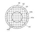
内側上部電極38は,サセプタ16に載置されたウェハW上に所定の混合ガスを噴出するシャワーヘッドを構成している。内側上部電極38は,多数のガス噴出孔60aを有する円形状の電極板60と,電極板60の上面側を着脱自在に支持する電極支持体62を備えている。電極支持体62は,電極板60と同じ径の円盤形状に形成され,内部に円形状のバッファ室63が形成されている。バッファ室63内には,例えば図2に示すようにOリングからなる環状隔壁部材64が設けられ,バッファ室63を中心部側の第1のバッファ室63aと外周部側の第2のバッファ室63bに分割している。第1のバッファ室63aは,サセプタ16上のウェハWの中央部に対向し,第2のバッファ室63bは,サセプタ16上のウェハWの外周部に対向している。各バッファ室63a,63bの下面には,ガス噴出孔60aが連通しており,第1のバッファ室63aからは,ウェハWの中央部に,第2のバッファ室63bからは,ウェハWの外周部に向けて所定の混合ガスを噴出できる。なお,各バッファ室63に所定の混合ガスを供給するガス供給装置100については後述する。 The inner
電極支持体62の上面には,図1に示すように上部給電棒48に接続された下部給電筒70が電気的に接続されている。下部給電筒70には,可変コンデンサ72が設けられている。可変コンデンサ72は,第1の高周波電源54による高周波電圧により外側上部電極36の直下に形成される電界強度と,内側上部電極38の直下に形成される電界強度との相対的な比率を調整できる。 As shown in FIG. 1, a lower power supply cylinder 70 connected to the upper
処理容器10の底部には,排気口74が形成されている。排気口74は,排気管76を通じて,真空ポンプなどを備えた排気装置78に接続されている。排気装置78により,処理容器10内の所望の真空度に減圧できる。 An
サセプタ16には,整合器80を介して第2の高周波電源82が電気的に接続されている。第2の高周波電源82は,例えば2MHz〜20MHzの範囲,例えば20MHzの周波数の高周波電圧を出力できる。 A second high
内側上部電極38には,第1の高周波電源54からの高周波を遮断し,第2の高周波電源82からの高周波をグランドに通すためのローパスフィルタ84が電気的に接続されている。サセプタ16には,第1の高周波電源54からの高周波をグランドに通すためのハイパスフィルタ86が電気的に接続されている。 The inner
プラズマエッチング装置1には,直流電源22,第1の高周波電源54及び第2の高周波電源82などのエッチング処理を実行するための各種諸元の動作を制御する装置制御部90が設けられている。 The plasma etching apparatus 1 is provided with an
次に,プラズマエッチング装置1の内側上部電極38に混合ガスを供給するガス供給装置100について説明する。 Next, the
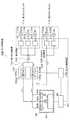
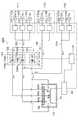
ガス供給装置100は,図3に示すように複数,例えば3つのガス供給源110a,110b,110cが収容された第1のガスボックス111と,複数,例えば2つの付加ガス供給源112a,112bが収容された第2のガスボックス113を備えている。本実施の形態においては,例えばガス供給源110aには,エッチングガスとしての例えばフロロカーボン系のフッ素化合物,例えばCF4,C4F6,C4F8,C5F8などのCXFYガスが封入され,ガス供給源110bには,例えばCF系の反応生成物のデポをコントロールするガスとしての例えばO2ガスが封入され,ガス供給源110cには,キャリアガスとしての希ガス,例えばArガスが封入されている。また,付加ガス供給源112aには,例えばエッチングを促進可能なCXFYガスが封入され,付加ガス供給源112bには,例えばCF系の反応生成物のデポをコントロール可能なO2ガスが封入されている。As shown in FIG. 3, the
第1のガスボックス111の各ガス供給源110a〜110cには,各ガス供給源110a〜110cからの各種ガスが合流され混合される混合配管120が接続されている。混合配管120には,各ガス供給源110a〜110cからのガスの流量を調整するマスフローコントローラ121がガス供給源毎に設けられている。混合配管120には,混合配管120で混合された混合ガスを分流する第1の分岐配管122と第2の分岐配管123が接続されている。第1の分岐配管122は,上記処理容器10の内側上部電極38の第1のバッファ室63aに接続されている。第2の分岐配管123は,内側上部電極38の第2のバッファ室63bに接続されている。 The
第1の分岐配管122には,圧力調整部124が設けられている。同様に第2の分岐配管123には,圧力調整部125が設けられている。圧力調整部124は,圧力計124aとバルブ124bを備えている。同様に圧力調整部125は,圧力計125aとバルブ125bを備えている。圧力調整部124の圧力計124aによる計測結果と,圧力調整部125の圧力計125aによる計測結果は,圧力比制御装置126に出力できる。圧力比制御装置126は,圧力計124a,125aの計測結果に基づいて,各バルブ124b,125bの開閉度を調整し,第1の分岐配管122と第2の分岐配管123に分流される混合ガスの圧力比,つまり流量比を制御できる。また,圧力比制御装置126は,供給ガスの設定時において,後述する第2のガスボックス113から第2の分岐配管123に付加ガスが供給されていない状態で,第1の分岐配管122と第2の分岐配管123を流れる混合ガスの圧力比を所定の目標圧力比に調整し,その状態でバルブ124b,125bの開閉度を固定することができる。 The
第2のガスボックス113の各付加ガス供給源112a,112bには,例えば第2の分岐配管123に連通する付加ガス供給配管130が接続されている。例えば付加ガス供給配管130は,各付加ガス供給源112a,112bに接続され,途中で集合して第2の分岐配管123に接続されている。付加ガス供給配管130は,圧力調整部125の下流側に接続されている。付加ガス供給配管130には,各付加ガス供給源112a,112bからの付加ガスの流量を調整するマスフローコントローラ131が付加ガス供給源毎に設けられている。かかる構成により,第2のガスボックス113の付加ガスを選択して或いは混合させて第2の分岐配管123に供給することができる。なお,本実施の形態では,第2のガスボックス113,付加ガス供給源112a,112b,付加ガス供給配管130及びマスフローコントローラ131により付加ガス供給装置が構成されている。 For example, an additional
第1のガスボックス111におけるマスフローコントローラ121と,第2のガスボックス113におけるマスフローコントローラ131の動作は,例えばプラズマエッチング装置1の装置制御部90により制御されている。したがって,装置制御部90により,第1のガスボックス111及び第2のガスボックス113からの各種ガスの供給の開始と停止,各種ガスのガス流量を制御できる。 The operations of the
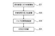
次に,以上のように構成されたガス供給装置100の動作について説明する。図4は,処理容器10に供給される混合ガスのガス成分や流量を設定する際のフロー図である。先ず,装置制御部90の指示信号により,第1のガスボックス111内の予め設定されているガスが所定流量で混合配管120に流される(図4中の工程S1)。例えば,ガス供給源110a〜110cのCXFYガス,O2ガス及びArガスがそれぞれ所定流量で供給され,混合配管120において混合されて,所定の混合比のCXFYガス,O2ガス及びArガスからなる混合ガスが生成される。続いて,圧力比制御装置126により,圧力計124a,125aの計測結果に基づいて,バルブ124b,125bの開閉度が調整され,第1の分岐配管122及び第2の分岐配管123に流れる混合ガスの圧力比が目標圧力比に調整される(図4中の工程S2)。これにより,第1の分岐配管122を通じて第1のバッファ室63aに供給される混合ガスのガス成分(混合比)と流量が設定される。また,第2の分岐配管123が通じる第2のバッファ室63bには,この時点で,少なくとも第1のバッファ室63aと同じ混合ガス,つまりエッチング処理が可能な混合ガスが供給されている。Next, the operation of the
そして,第1の分岐配管122及び第2の分岐配管123に流れる混合ガスが目標圧力比に調整され安定すると,圧力比制御装置126により,圧力調整部124,125のバルブ124b,125bの開閉度が固定される(図4中の工程S3)。バルブ124b,125bの開閉度が固定されるのを見計らって,装置制御部90の指示信号により,第2のガスボックス113から予め設定されている付加ガスが所定流量で付加ガス供給配管130に流される(図4中の工程S4)。この第2のガスボックス113からの付加ガスの供給を開始させるための指示信号は,装置制御部90に予め設定された設定時間が経過することにより送信される。例えば付加ガス供給源112aからエッチングを促進可能なCXFYガス,例えばCF4ガスが所定の流量で供給され,第2の分岐配管123に合流される。これにより,第2の分岐配管123が連通する第2のバッファ室63bには,第1のバッファ室63aよりもCF4ガスの多い混合ガスが供給される。こうして,第2のバッファ室63bに供給される混合ガスのガス成分及び流量が設定される。なお,この第2の分岐配管123への付加ガスの供給により第1の分岐配管122と第2の分岐配管123の圧力比は変動するが,バルブ124b,125bが固定されているので,第1のバッファ室63aには,当初の流量の混合ガスが供給される。When the mixed gas flowing in the
そして,プラズマエッチング装置1では,減圧雰囲気の下,サセプタ16上のウェハWの中心部付近には,第1のバッファ室63aからの混合ガスが供給され,ウェハWの外周部には,第2のバッファ室63bからのCF4ガスの多い混合ガスが供給される。これにより,ウェハWの外周部におけるエッチング特性がウェハWの中心部に対して相対的に調整され,ウェハW面内のエッチング特性が均一になる。In the plasma etching apparatus 1, the mixed gas from the
以上の実施の形態によれば,第1のガスボックスからの複数種類のガスが混合配管120で混合され,その混合ガスが第1の分岐配管122と第2の分岐配管123に分流して処理容器10の第1のバッファ室63aと第2のバッファ室63bに供給される。第2の分岐配管123には,エッチング特性を調整するための付加ガスが供給され,第2のバッファ室63bには,第1のバッファ室63aと異なる成分で流量の混合ガスが供給される。このように,処理容器10における第1のバッファ室63aと第2のバッファ室63bに供給される混合ガスのガス成分や流量を,簡単な配管構成で任意に調整できる。 According to the above embodiment, a plurality of types of gas from the first gas box are mixed in the mixing
また,第1の分岐配管122と第2の分岐配管123の流量を圧力調整部124,125により調整したので,プラズマエッチング装置1のようにガスの供給先の圧力が極めて低い場合であっても,供給配管の流量調整を適正に行うことができる。 Further, since the flow rates of the
以上の実施の形態において,第2の分岐配管123には,エッチングを促進可能なCF4ガスを供給したが,例えばウェハWの中心部よりも外周部の方がCF系の反応生成物の堆積が多く,エッチングが遅れるような場合には,第2の分岐配管123に,CF系の反応生成物を除去するO2ガスを供給してもよい。また,第2の分岐配管123には,CF4ガスとO2ガスの両方を所定の混合比で混合して供給してもよい。In the above embodiment, the CF4 gas capable of promoting the etching is supplied to the
上記実施の形態では,第2のガスボックス113から第2の分岐配管123に付加ガスを供給するタイミングは,装置制御部90における設定時間により予め設定されていたが,例えば装置制御部90が圧力比制御装置126を通じて圧力計124a,125bによる計測値を監視し,所望の目標圧力比に安定した時点で,第2のガスボックス113側に指示信号を発信して,付加ガスの供給を開始してもよい。 In the above embodiment, the timing of supplying the additional gas from the
また,第2のガスボックス113の各付加ガス供給源112a,112bを,付加ガス供給配管130によって第1の分岐配管122側にも接続してもよい。こうすることにより,必要な場合には,第1のバッファ室63に供給される混合ガスのガス成分や流量も微調整できる。 Further, the additional
以上の実施の形態で記載した第2のガスボックス113には,CF4ガスとO2ガスの付加ガス供給源が設けられていたが,エッチングを促進したり抑制したりする他の付加ガス,例えばエッチングを促進するガスとして,CHF3,CH2F2,CH3FなどのCXHYFZガス,CF系反応生成物をコントロールするガスとして,N2ガスやCOガス,希釈ガスとして,XeガスやHeガスなどの付加ガス供給源が設けられてもよい。この他,以上の実施の形態で記載した第1のガスボックス111や第2のガスボックス113に収容されるガスのガス種や数は,被エッチング材料やプロセス条件などに応じて,任意に選択できる。In the
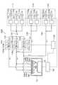
以上の実施の形態で記載したガス供給装置100は,処理容器10における第1のバッファ室63aと第2のバッファ室63bの二箇所に混合ガスを供給していたが,処理容器10の三箇所以上に混合ガスを供給してもよい。図5は,かかる一例を示すものであり,例えば内側上部電極38には,同心円状の3つのバッファ室63が形成されている。つまり,内側上部電極38の第2のバッファ室63bのさらに外側に,環状の第3のバッファ室63cが形成されている。この場合,混合配管120には,第1,第2の分岐配管122,123に加えて,さらに第3の分岐配管150が分岐されている。第3の分岐配管150は,第3のバッファ室63cに接続されている。第3の分岐配管150には,他の分岐配管122,123と同様に圧力調整室151,圧力計151a及びバルブ151bが設けられている。また,この例のガス供給装置100には,第3の分岐配管150に所定の付加ガスを供給するための第3のガスボックス152が設けられている。第3のガスボックス152は,例えば第2のガスボックス113と同様の構成を有し,CF4の付加ガス供給源153aとO2ガスの付加ガス供給源153bを備えている。各付加ガス供給源153a,153bは,付加ガス供給配管154によって第3の分岐配管150に接続され,付加ガス供給配管154には,付加ガス供給源毎にマスフローコントローラ155が設けられている。なお,この他の部分の構成は,上記実施の形態と同様なので,説明を省略する。In the
そして,各バッファ室63a〜63cに混合ガスが供給される際には,第1のガスボックス111の例えばガス供給源110a〜110cのガスが混合配管120に供給され,混合された後,その混合ガスが3つの分岐配管122,123,150に分流される。圧力比制御装置126により,分岐配管122,123,150の圧力比が所定の目標圧力比に調整され,その後バルブ124b,125b,151bの開閉度が固定される。これにより,第1の分岐配管122が連通する第1のバッファ室63aの混合ガスのガス成分と流量が設定される。その後,第2のガスボックス133から付加ガス供給配管130を通じて所定種類の所定流量の付加ガスが第2の分岐配管123に供給され,また第3のガスボックス152から付加ガス供給配管154を通じて所定種類の所定流量の付加ガスが第3の分岐配管150に供給される。こうして,第2のバッファ室63b,第3のバッファ室63cに供給される混合ガスのガス成分と流量が設定される。かかる場合においても,簡単な配管構成で,処理容器10の三箇所に任意の混合ガスを供給できる。 When the mixed gas is supplied to each of the
以上の実施の形態では,ガス供給装置100から供給された混合ガスが,処理容器10の上部からウェハWに向けて噴出されていたが,処理容器10の他の部分,例えば処理容器10におけるプラズマ生成空間PSの側面からも混合ガスが噴出されてもよい。かかる場合,例えば図6に示すように上記第3の分岐配管150が処理容器10の両側面に接続される。かかる場合,プラズマ生成空間PSの上部と側部からそれぞれ所定の混合ガスを供給できるので,プラズマ生成空間PS内のガス濃度を調整し,ウェハ面内のエッチング特性の均一性をさらに向上することができる。 In the above embodiment, the mixed gas supplied from the
以上の実施の形態では,分岐配管の流量を圧力調整部により調整していたが,マスフローコントローラを用いてもよい。また,以上の実施の形態で記載したガス供給装置100は,プラズマエッチング装置1に混合ガスを供給するものであったが,混合ガスが供給される他の基板処理装置,例えばプラズマCVD装置,スパッタリング装置,熱酸化装置などの成膜装置にも本発明は適用できる。さらに本発明は,ウェハ以外の例えばFPD(フラットパネルディスプレイ),フォトマスク用のマスクレチクルなどの他の基板処理装置やMEMS(マイクロエレクトロメカニカルシステム)製造装置にも適用できる。 In the above embodiment, the flow rate of the branch pipe is adjusted by the pressure adjusting unit, but a mass flow controller may be used. Further, the
本発明は,基板の処理容器の複数個所に任意の混合ガスを供給する際に有用である。 The present invention is useful when supplying an arbitrary mixed gas to a plurality of locations in a substrate processing container.
1 プラズマエッチング装置
10 処理容器
38 内側上部電極
63 バッファ室
90 装置制御部
100 ガス供給装置
111 第1のガスボックス
113 第2のガスボックス
120 混合配管
122 第1の分岐配管
123 第2の分岐配管
124,125 圧力調整部
130 付加ガス供給配管
126 圧力比制御装置
W ウェハDESCRIPTION OF SYMBOLS 1
Claims (8)
Translated fromJapanese複数のガス供給源と,
前記複数のガス供給源から供給される複数のガスを混合する混合配管と,
前記混合配管で混合された混合ガスを分流して処理容器の複数箇所に供給する複数の分岐配管と,
前記分岐配管の内の一部のみであって少なくとも一つの分岐配管を流れる混合ガスに所定の付加ガスを供給する付加ガス供給装置と,を備え,
ガス流量を調整するためのバルブと圧力計を各分岐配管に備え,
さらに,前記圧力計の計測結果に基づいて,前記バルブの開閉度を調整して,前記混合配管の混合ガスを所定の圧力比で前記分岐配管に分流する圧力比制御装置を備え,
前記付加ガス供給装置は,前記分岐配管に連通する付加ガス供給配管を有し,
前記付加ガス供給配管は,前記圧力計と前記バルブの下流側に接続され,
前記圧力比制御装置は,前記付加ガス供給装置から分岐配管に前記付加ガスを供給しない状態で,前記各分岐配管に分流される混合ガスの圧力比を前記バルブにより所定の圧力比に調整し,その状態で前記バルブの開閉度を固定することを特徴とする,ガス供給装置。A gas supply device for supplying a gas to a processing container for processing a substrate,
Multiple gas sources;
A mixing pipe for mixing a plurality of gases supplied from the plurality of gas supply sources;
A plurality of branch pipes for dividing the mixed gas mixed in the mixing pipe and supplying the mixed gas to a plurality of locations in the processing vessel;
An additional gas supply device for supplying a predetermined additional gas to a mixed gas flowing through at least one branch pipe andonly a part of the branch pipe;
Each branch pipe is equipped with a valve and pressure gauge to adjust the gas flow rate.
And a pressure ratio control device that adjusts the degree of opening and closing of the valve based on the measurement result of the pressure gauge and diverts the mixed gas of the mixing pipe to the branch pipe at a predetermined pressure ratio,
The additional gas supply device has an additional gas supply pipe communicating with the branch pipe;
The additional gas supply pipe is connected to the downstream side of the pressure gauge and the valve,
The pressure ratio control device adjusts the pressure ratio of the mixed gas divided into each branch pipe to a predetermined pressure ratio by the valve without supplying the additional gas from the additional gas supply device to the branch pipe, In this state, the opening and closing degree of the valve is fixed .
複数のガス供給源と,Multiple gas sources;
前記複数のガス供給源から供給される複数のガスを混合する混合配管と,A mixing pipe for mixing a plurality of gases supplied from the plurality of gas supply sources;
前記混合配管で混合された混合ガスを分流して処理容器の複数箇所に供給する複数の分岐配管と,A plurality of branch pipes for dividing the mixed gas mixed in the mixing pipe and supplying the mixed gas to a plurality of locations in the processing vessel;
前記分岐配管の内の一部のみであって少なくとも一つの分岐配管を流れる混合ガスに所定の付加ガスを供給する付加ガス供給装置と,を備え,An additional gas supply device for supplying a predetermined additional gas to a mixed gas flowing through at least one branch pipe and only a part of the branch pipe;
前記処理容器内に配置され,前記処理容器内の処理空間にガスを吐出させるためのシャワーヘッドを有し,A shower head disposed in the processing vessel, for discharging gas into the processing space in the processing vessel;
前記複数の分岐配管は,前記シャワーヘッドに接続され,The plurality of branch pipes are connected to the shower head,
ガス流量を調整するためのバルブと圧力計を各分岐配管に備え,Each branch pipe is equipped with a valve and pressure gauge to adjust the gas flow rate.
さらに,前記圧力計の計測結果に基づいて,前記バルブの開閉度を調整して,前記混合配管の混合ガスを所定の圧力比で前記分岐配管に分流する圧力比制御装置を備え,And a pressure ratio control device that adjusts the degree of opening and closing of the valve based on the measurement result of the pressure gauge and diverts the mixed gas of the mixing pipe to the branch pipe at a predetermined pressure ratio,
前記付加ガス供給装置は,前記分岐配管に連通する付加ガス供給配管を有し,The additional gas supply device has an additional gas supply pipe communicating with the branch pipe;
前記付加ガス供給配管は,前記圧力計と前記バルブの下流側に接続され,The additional gas supply pipe is connected to the downstream side of the pressure gauge and the valve,
前記圧力比制御装置は,前記付加ガス供給装置から分岐配管に前記付加ガスを供給しない状態で,前記各分岐配管に分流される混合ガスの圧力比を前記バルブにより所定の圧力比に調整し,その状態で前記バルブの開閉度を固定することを特徴とする基板処理装置。The pressure ratio control device adjusts the pressure ratio of the mixed gas divided into each branch pipe to a predetermined pressure ratio by the valve without supplying the additional gas from the additional gas supply device to the branch pipe, In this state, the opening / closing degree of the valve is fixed.
前記複数のガス供給源から供給される複数のガスを混合する混合配管と,A mixing pipe for mixing a plurality of gases supplied from the plurality of gas supply sources;
前記混合配管で混合された混合ガスを分流して処理容器の複数箇所に供給する複数の分岐配管と,A plurality of branch pipes for dividing the mixed gas mixed in the mixing pipe and supplying the mixed gas to a plurality of locations in the processing vessel;
前記分岐配管の内の一部のみであって少なくとも一つの分岐配管を流れる混合ガスに所定の付加ガスを供給する付加ガス供給装置と,を有し,An additional gas supply device for supplying a predetermined additional gas to a mixed gas flowing through at least one branch pipe and only a part of the branch pipe;
ガス流量を調整するためのバルブと圧力計を各分岐配管に備えたガス供給装置を用いた供給ガス設定方法であって,A supply gas setting method using a gas supply device provided with a valve and a pressure gauge for adjusting a gas flow rate in each branch pipe,
前記付加ガス供給装置から前記分岐配管に付加ガスを供給しない状態で,前記混合配管から各分岐配管に分流される混合ガスの圧力比を前記バルブにより所定の混合比に調整し,その後前記分岐配管の前記バルブの開閉度を固定する工程と,The pressure ratio of the mixed gas branched from the mixing pipe to each branch pipe is adjusted to a predetermined mixing ratio by the valve without supplying additional gas from the additional gas supply device to the branch pipe, and then the branch pipe Fixing the opening / closing degree of the valve of
その後,前記付加ガス供給装置から所定の前記分岐配管に前記圧力計と前記バルブの下流側において所定流量の付加ガスを供給する工程と,を有することを特徴とする,供給ガス設定方法。And a step of supplying a predetermined flow rate of the additional gas downstream from the pressure gauge and the valve from the additional gas supply device to the predetermined branch pipe.
Priority Applications (7)
| Application Number | Priority Date | Filing Date | Title |
|---|---|---|---|
| JP2004357292AJP4358727B2 (en) | 2004-12-09 | 2004-12-09 | Gas supply apparatus, substrate processing apparatus, and supply gas setting method |
| US11/296,209US20060124169A1 (en) | 2004-12-09 | 2005-12-08 | Gas supply unit, substrate processing apparatus, and supply gas setting method |
| TW094143443ATWI441254B (en) | 2004-12-09 | 2005-12-08 | A gas supply device, a substrate processing device, and a supply gas setting method |
| KR1020050119216AKR100753692B1 (en) | 2004-12-09 | 2005-12-08 | Gas supply unit, substrate processing apparatus and supply gas setting method |
| CNB2005101303873ACN100390933C (en) | 2004-12-09 | 2005-12-09 | Gas supply device, substrate processing device, and supply gas setting method |
| US12/651,165US8906193B2 (en) | 2004-12-09 | 2009-12-31 | Gas supply unit, substrate processing apparatus and supply gas setting method |
| US13/691,125US9441791B2 (en) | 2004-12-09 | 2012-11-30 | Gas supply unit, substrate processing apparatus and supply gas setting method |
Applications Claiming Priority (1)
| Application Number | Priority Date | Filing Date | Title |
|---|---|---|---|
| JP2004357292AJP4358727B2 (en) | 2004-12-09 | 2004-12-09 | Gas supply apparatus, substrate processing apparatus, and supply gas setting method |
Publications (3)
| Publication Number | Publication Date |
|---|---|
| JP2006165399A JP2006165399A (en) | 2006-06-22 |
| JP2006165399A5 JP2006165399A5 (en) | 2008-01-31 |
| JP4358727B2true JP4358727B2 (en) | 2009-11-04 |
Family
ID=36667053
Family Applications (1)
| Application Number | Title | Priority Date | Filing Date |
|---|---|---|---|
| JP2004357292AExpired - Fee RelatedJP4358727B2 (en) | 2004-12-09 | 2004-12-09 | Gas supply apparatus, substrate processing apparatus, and supply gas setting method |
Country Status (4)
| Country | Link |
|---|---|
| JP (1) | JP4358727B2 (en) |
| KR (1) | KR100753692B1 (en) |
| CN (1) | CN100390933C (en) |
| TW (1) | TWI441254B (en) |
Cited By (3)
| Publication number | Priority date | Publication date | Assignee | Title |
|---|---|---|---|---|
| KR20160009542A (en) | 2013-05-15 | 2016-01-26 | 도쿄엘렉트론가부시키가이샤 | Plasma etching device and plasma etching method |
| US9349619B2 (en) | 2011-08-31 | 2016-05-24 | Tokyo Electron Limited | Plasma etching method and plasma etching apparatus |
| KR20180086151A (en) | 2017-01-20 | 2018-07-30 | 도쿄엘렉트론가부시키가이샤 | Plasma processing apparatus |
Families Citing this family (20)
| Publication number | Priority date | Publication date | Assignee | Title |
|---|---|---|---|---|
| JP4550507B2 (en) | 2004-07-26 | 2010-09-22 | 株式会社日立ハイテクノロジーズ | Plasma processing equipment |
| JP4895167B2 (en)* | 2006-01-31 | 2012-03-14 | 東京エレクトロン株式会社 | Gas supply apparatus, substrate processing apparatus, and gas supply method |
| JP5211450B2 (en)* | 2006-08-15 | 2013-06-12 | 東京エレクトロン株式会社 | Substrate processing apparatus, substrate processing method, and storage medium |
| US20080078746A1 (en) | 2006-08-15 | 2008-04-03 | Noriiki Masuda | Substrate processing system, gas supply unit, method of substrate processing, computer program, and storage medium |
| JP5192214B2 (en) | 2007-11-02 | 2013-05-08 | 東京エレクトロン株式会社 | Gas supply apparatus, substrate processing apparatus, and substrate processing method |
| JP5378706B2 (en)* | 2008-05-22 | 2013-12-25 | 東京エレクトロン株式会社 | Plasma processing apparatus and processing gas supply apparatus used therefor |
| JP5452133B2 (en)* | 2009-08-27 | 2014-03-26 | 株式会社日立ハイテクノロジーズ | Plasma processing apparatus and plasma processing method |
| JP5562712B2 (en)* | 2010-04-30 | 2014-07-30 | 東京エレクトロン株式会社 | Gas supply equipment for semiconductor manufacturing equipment |
| JP5689294B2 (en) | 2010-11-25 | 2015-03-25 | 東京エレクトロン株式会社 | Processing equipment |
| JP2014003234A (en)* | 2012-06-20 | 2014-01-09 | Tokyo Electron Ltd | Plasma processing apparatus and plasma processing method |
| JP6034655B2 (en) | 2012-10-25 | 2016-11-30 | 東京エレクトロン株式会社 | Plasma processing equipment |
| US9620417B2 (en)* | 2014-09-30 | 2017-04-11 | Taiwan Semiconductor Manufacturing Co., Ltd. | Apparatus and method of manufacturing fin-FET devices |
| US20180149315A1 (en)* | 2015-05-17 | 2018-05-31 | Entegris, Inc. | Gas cabinets |
| JP6502779B2 (en)* | 2015-07-29 | 2019-04-17 | 東京エレクトロン株式会社 | Method of inspecting leak of valve of gas supply system |
| CH713539A1 (en)* | 2017-03-03 | 2018-09-14 | Pelco Sarl | Automatic gas mixer. |
| JP7296854B2 (en)* | 2019-11-07 | 2023-06-23 | 東京エレクトロン株式会社 | Gas supply method and substrate processing apparatus |
| JP7685507B2 (en)* | 2020-01-13 | 2025-05-29 | ラム リサーチ コーポレーション | Gas distribution plate with multiple zones to optimize groove contours |
| JP7727528B2 (en)* | 2021-12-23 | 2025-08-21 | 東京エレクトロン株式会社 | Plasma processing equipment |
| CN117198848A (en)* | 2022-06-01 | 2023-12-08 | 长鑫存储技术有限公司 | Gas distribution device, plasma processing device and method |
| CN114774887A (en)* | 2022-06-22 | 2022-07-22 | 拓荆科技(北京)有限公司 | Gas delivery device, method and semiconductor deposition equipment |
Family Cites Families (7)
| Publication number | Priority date | Publication date | Assignee | Title |
|---|---|---|---|---|
| JPH05136098A (en)* | 1991-11-15 | 1993-06-01 | Seiko Epson Corp | Semiconductor device manufacturing apparatus and semiconductor device manufacturing method |
| US5916369A (en)* | 1995-06-07 | 1999-06-29 | Applied Materials, Inc. | Gas inlets for wafer processing chamber |
| JPH09289170A (en)* | 1996-04-23 | 1997-11-04 | Sony Corp | Semiconductor manufacturing equipment |
| US6210482B1 (en)* | 1999-04-22 | 2001-04-03 | Fujikin Incorporated | Apparatus for feeding gases for use in semiconductor manufacturing |
| CN1240113C (en)* | 2002-08-20 | 2006-02-01 | 东京毅力科创株式会社 | Plasma etching method and device |
| JP4127779B2 (en)* | 2002-08-28 | 2008-07-30 | 株式会社神戸製鋼所 | Hot isostatic pressurizing device and hot isostatic pressurizing method |
| US20040050326A1 (en)* | 2002-09-12 | 2004-03-18 | Thilderkvist Karin Anna Lena | Apparatus and method for automatically controlling gas flow in a substrate processing system |
- 2004
- 2004-12-09JPJP2004357292Apatent/JP4358727B2/ennot_activeExpired - Fee Related
- 2005
- 2005-12-08TWTW094143443Apatent/TWI441254B/ennot_activeIP Right Cessation
- 2005-12-08KRKR1020050119216Apatent/KR100753692B1/ennot_activeExpired - Fee Related
- 2005-12-09CNCNB2005101303873Apatent/CN100390933C/ennot_activeExpired - Fee Related
Cited By (5)
| Publication number | Priority date | Publication date | Assignee | Title |
|---|---|---|---|---|
| US9349619B2 (en) | 2011-08-31 | 2016-05-24 | Tokyo Electron Limited | Plasma etching method and plasma etching apparatus |
| US9887109B2 (en) | 2011-08-31 | 2018-02-06 | Tokyo Electron Limited | Plasma etching method and plasma etching apparatus |
| KR20160009542A (en) | 2013-05-15 | 2016-01-26 | 도쿄엘렉트론가부시키가이샤 | Plasma etching device and plasma etching method |
| US9583315B2 (en) | 2013-05-15 | 2017-02-28 | Tokyo Electron Limited | Plasma etching apparatus and plasma etching method |
| KR20180086151A (en) | 2017-01-20 | 2018-07-30 | 도쿄엘렉트론가부시키가이샤 | Plasma processing apparatus |
Also Published As
| Publication number | Publication date |
|---|---|
| JP2006165399A (en) | 2006-06-22 |
| CN1787170A (en) | 2006-06-14 |
| CN100390933C (en) | 2008-05-28 |
| KR100753692B1 (en) | 2007-08-30 |
| KR20060065510A (en) | 2006-06-14 |
| TW200633049A (en) | 2006-09-16 |
| TWI441254B (en) | 2014-06-11 |
Similar Documents
| Publication | Publication Date | Title |
|---|---|---|
| JP4358727B2 (en) | Gas supply apparatus, substrate processing apparatus, and supply gas setting method | |
| US8906193B2 (en) | Gas supply unit, substrate processing apparatus and supply gas setting method | |
| JP4911984B2 (en) | Gas supply apparatus, substrate processing apparatus, gas supply method, and shower head | |
| JP4895167B2 (en) | Gas supply apparatus, substrate processing apparatus, and gas supply method | |
| US8790529B2 (en) | Gas supply system, substrate processing apparatus and gas supply method | |
| JP4460288B2 (en) | Substrate processing apparatus and power distribution method | |
| JP4393844B2 (en) | Plasma film forming apparatus and plasma film forming method | |
| US8561572B2 (en) | Gas supply system, substrate processing apparatus and gas supply method | |
| US8261691B2 (en) | Plasma processing apparatus | |
| US20040031564A1 (en) | Switched uniformity control | |
| JPH1167737A (en) | Plasma processing equipment | |
| JP2019096835A (en) | Plasma processing apparatus and plasma processing method | |
| JP2007208194A (en) | Gas supply apparatus, substrate processing apparatus, and gas supply method | |
| JP4357487B2 (en) | Gas supply apparatus, substrate processing apparatus, and gas supply method | |
| JP4410117B2 (en) | Gas setting method, gas setting device, etching device and substrate processing system |
Legal Events
| Date | Code | Title | Description |
|---|---|---|---|
| A521 | Request for written amendment filed | Free format text:JAPANESE INTERMEDIATE CODE: A523 Effective date:20071207 | |
| A621 | Written request for application examination | Free format text:JAPANESE INTERMEDIATE CODE: A621 Effective date:20071207 | |
| A977 | Report on retrieval | Free format text:JAPANESE INTERMEDIATE CODE: A971007 Effective date:20090512 | |
| A131 | Notification of reasons for refusal | Free format text:JAPANESE INTERMEDIATE CODE: A131 Effective date:20090526 | |
| A521 | Request for written amendment filed | Free format text:JAPANESE INTERMEDIATE CODE: A523 Effective date:20090709 | |
| TRDD | Decision of grant or rejection written | ||
| A01 | Written decision to grant a patent or to grant a registration (utility model) | Free format text:JAPANESE INTERMEDIATE CODE: A01 Effective date:20090804 | |
| A01 | Written decision to grant a patent or to grant a registration (utility model) | Free format text:JAPANESE INTERMEDIATE CODE: A01 | |
| A61 | First payment of annual fees (during grant procedure) | Free format text:JAPANESE INTERMEDIATE CODE: A61 Effective date:20090806 | |
| FPAY | Renewal fee payment (event date is renewal date of database) | Free format text:PAYMENT UNTIL: 20120814 Year of fee payment:3 | |
| R150 | Certificate of patent or registration of utility model | Ref document number:4358727 Country of ref document:JP Free format text:JAPANESE INTERMEDIATE CODE: R150 Free format text:JAPANESE INTERMEDIATE CODE: R150 | |
| FPAY | Renewal fee payment (event date is renewal date of database) | Free format text:PAYMENT UNTIL: 20120814 Year of fee payment:3 | |
| FPAY | Renewal fee payment (event date is renewal date of database) | Free format text:PAYMENT UNTIL: 20150814 Year of fee payment:6 | |
| R250 | Receipt of annual fees | Free format text:JAPANESE INTERMEDIATE CODE: R250 | |
| R250 | Receipt of annual fees | Free format text:JAPANESE INTERMEDIATE CODE: R250 | |
| R250 | Receipt of annual fees | Free format text:JAPANESE INTERMEDIATE CODE: R250 | |
| R250 | Receipt of annual fees | Free format text:JAPANESE INTERMEDIATE CODE: R250 | |
| R250 | Receipt of annual fees | Free format text:JAPANESE INTERMEDIATE CODE: R250 | |
| R250 | Receipt of annual fees | Free format text:JAPANESE INTERMEDIATE CODE: R250 | |
| R250 | Receipt of annual fees | Free format text:JAPANESE INTERMEDIATE CODE: R250 | |
| LAPS | Cancellation because of no payment of annual fees |