JP4358635B2 - Starter assembly for gas discharge lamp - Google Patents
Starter assembly for gas discharge lampDownload PDFInfo
- Publication number
- JP4358635B2 JP4358635B2JP2003570378AJP2003570378AJP4358635B2JP 4358635 B2JP4358635 B2JP 4358635B2JP 2003570378 AJP2003570378 AJP 2003570378AJP 2003570378 AJP2003570378 AJP 2003570378AJP 4358635 B2JP4358635 B2JP 4358635B2
- Authority
- JP
- Japan
- Prior art keywords
- gas discharge
- discharge lamp
- control unit
- lamp
- assembly
- Prior art date
- Legal status (The legal status is an assumption and is not a legal conclusion. Google has not performed a legal analysis and makes no representation as to the accuracy of the status listed.)
- Expired - Lifetime
Links
Images


Classifications
- B—PERFORMING OPERATIONS; TRANSPORTING
- B01—PHYSICAL OR CHEMICAL PROCESSES OR APPARATUS IN GENERAL
- B01D—SEPARATION
- B01D35/00—Filtering devices having features not specifically covered by groups B01D24/00 - B01D33/00, or for applications not specifically covered by groups B01D24/00 - B01D33/00; Auxiliary devices for filtration; Filter housing constructions
- B01D35/30—Filter housing constructions
- B—PERFORMING OPERATIONS; TRANSPORTING
- B65—CONVEYING; PACKING; STORING; HANDLING THIN OR FILAMENTARY MATERIAL
- B65D—CONTAINERS FOR STORAGE OR TRANSPORT OF ARTICLES OR MATERIALS, e.g. BAGS, BARRELS, BOTTLES, BOXES, CANS, CARTONS, CRATES, DRUMS, JARS, TANKS, HOPPERS, FORWARDING CONTAINERS; ACCESSORIES, CLOSURES, OR FITTINGS THEREFOR; PACKAGING ELEMENTS; PACKAGES
- B65D45/00—Clamping or other pressure-applying devices for securing or retaining closure members
- C—CHEMISTRY; METALLURGY
- C02—TREATMENT OF WATER, WASTE WATER, SEWAGE, OR SLUDGE
- C02F—TREATMENT OF WATER, WASTE WATER, SEWAGE, OR SLUDGE
- C02F9/00—Multistage treatment of water, waste water or sewage
- C02F9/20—Portable or detachable small-scale multistage treatment devices, e.g. point of use or laboratory water purification systems
- H—ELECTRICITY
- H01—ELECTRIC ELEMENTS
- H01J—ELECTRIC DISCHARGE TUBES OR DISCHARGE LAMPS
- H01J5/00—Details relating to vessels or to leading-in conductors common to two or more basic types of discharge tubes or lamps
- H01J5/50—Means forming part of the tube or lamps for the purpose of providing electrical connection to it
- H01J5/52—Means forming part of the tube or lamps for the purpose of providing electrical connection to it directly applied to or forming part of the vessel
- H—ELECTRICITY
- H01—ELECTRIC ELEMENTS
- H01J—ELECTRIC DISCHARGE TUBES OR DISCHARGE LAMPS
- H01J61/00—Gas-discharge or vapour-discharge lamps
- H01J61/02—Details
- H01J61/56—One or more circuit elements structurally associated with the lamp
- H—ELECTRICITY
- H05—ELECTRIC TECHNIQUES NOT OTHERWISE PROVIDED FOR
- H05B—ELECTRIC HEATING; ELECTRIC LIGHT SOURCES NOT OTHERWISE PROVIDED FOR; CIRCUIT ARRANGEMENTS FOR ELECTRIC LIGHT SOURCES, IN GENERAL
- H05B41/00—Circuit arrangements or apparatus for igniting or operating discharge lamps
- H05B41/02—Details
- H05B41/04—Starting switches
- H05B41/10—Starting switches magnetic only
- H—ELECTRICITY
- H05—ELECTRIC TECHNIQUES NOT OTHERWISE PROVIDED FOR
- H05B—ELECTRIC HEATING; ELECTRIC LIGHT SOURCES NOT OTHERWISE PROVIDED FOR; CIRCUIT ARRANGEMENTS FOR ELECTRIC LIGHT SOURCES, IN GENERAL
- H05B41/00—Circuit arrangements or apparatus for igniting or operating discharge lamps
- H05B41/14—Circuit arrangements
- H05B41/26—Circuit arrangements in which the lamp is fed by power derived from DC by means of a converter, e.g. by high-voltage DC
- H05B41/28—Circuit arrangements in which the lamp is fed by power derived from DC by means of a converter, e.g. by high-voltage DC using static converters
- H05B41/295—Circuit arrangements in which the lamp is fed by power derived from DC by means of a converter, e.g. by high-voltage DC using static converters with semiconductor devices and specially adapted for lamps with preheating electrodes, e.g. for fluorescent lamps
- H—ELECTRICITY
- H05—ELECTRIC TECHNIQUES NOT OTHERWISE PROVIDED FOR
- H05B—ELECTRIC HEATING; ELECTRIC LIGHT SOURCES NOT OTHERWISE PROVIDED FOR; CIRCUIT ARRANGEMENTS FOR ELECTRIC LIGHT SOURCES, IN GENERAL
- H05B41/00—Circuit arrangements or apparatus for igniting or operating discharge lamps
- H05B41/14—Circuit arrangements
- H05B41/36—Controlling
- B—PERFORMING OPERATIONS; TRANSPORTING
- B01—PHYSICAL OR CHEMICAL PROCESSES OR APPARATUS IN GENERAL
- B01D—SEPARATION
- B01D2201/00—Details relating to filtering apparatus
- B01D2201/30—Filter housing constructions
- B01D2201/301—Details of removable closures, lids, caps, filter heads
- B—PERFORMING OPERATIONS; TRANSPORTING
- B01—PHYSICAL OR CHEMICAL PROCESSES OR APPARATUS IN GENERAL
- B01D—SEPARATION
- B01D2201/00—Details relating to filtering apparatus
- B01D2201/34—Seals or gaskets for filtering elements
- C—CHEMISTRY; METALLURGY
- C02—TREATMENT OF WATER, WASTE WATER, SEWAGE, OR SLUDGE
- C02F—TREATMENT OF WATER, WASTE WATER, SEWAGE, OR SLUDGE
- C02F1/00—Treatment of water, waste water, or sewage
- C02F1/28—Treatment of water, waste water, or sewage by sorption
- C02F1/283—Treatment of water, waste water, or sewage by sorption using coal, charred products, or inorganic mixtures containing them
- C—CHEMISTRY; METALLURGY
- C02—TREATMENT OF WATER, WASTE WATER, SEWAGE, OR SLUDGE
- C02F—TREATMENT OF WATER, WASTE WATER, SEWAGE, OR SLUDGE
- C02F1/00—Treatment of water, waste water, or sewage
- C02F1/30—Treatment of water, waste water, or sewage by irradiation
- C02F1/32—Treatment of water, waste water, or sewage by irradiation with ultraviolet light
- C—CHEMISTRY; METALLURGY
- C02—TREATMENT OF WATER, WASTE WATER, SEWAGE, OR SLUDGE
- C02F—TREATMENT OF WATER, WASTE WATER, SEWAGE, OR SLUDGE
- C02F2201/00—Apparatus for treatment of water, waste water or sewage
- C02F2201/002—Construction details of the apparatus
- C02F2201/006—Cartridges
Landscapes
- Chemical & Material Sciences (AREA)
- Engineering & Computer Science (AREA)
- Chemical Kinetics & Catalysis (AREA)
- Hydrology & Water Resources (AREA)
- Health & Medical Sciences (AREA)
- Environmental & Geological Engineering (AREA)
- Water Supply & Treatment (AREA)
- Life Sciences & Earth Sciences (AREA)
- Organic Chemistry (AREA)
- Clinical Laboratory Science (AREA)
- Mechanical Engineering (AREA)
- Circuit Arrangements For Discharge Lamps (AREA)
- Physical Water Treatments (AREA)
- Water Treatment By Sorption (AREA)
Description
Translated fromJapanese本発明は、ガス放電ランプのためのスタータに関し、さらに特に、ガス放電ランプを起動するために使用される磁気スイッチと制御回路とを有するスタータアセンブリに関する。 The present invention relates to a starter for a gas discharge lamp, and more particularly to a starter assembly having a magnetic switch and a control circuit used to activate the gas discharge lamp.
本発明は、2002年2月19日付で出願された標題「ユースポイント水処理システム(Point Of Use Water Treatment System)」の米国仮出願番号60/357,908の35 USC §119(e)による利益を請求する。 The present invention is benefit from 35 USC §119 (e) of US Provisional Application No. 60 / 357,908, entitled “Point Of Use Water Treatment System,” filed on Feb. 19, 2002. To charge.
本出願には、2002年4月26日付で出願された標題「誘導駆動ランプアセンブリ(Inductively Powered Lamp Assembly)」の米国特許出願番号10/133,860と、2000年6月12日付で出願された標題「流体処理システム」の米国特許出願番号90/592,194と、2002年9月18日付で出願された標題「誘導結合バラスト回路」の米国特許出願番号10/246,155と、標題「誘導結合バラストを有する水処理システム」の発行された米国特許第6,436,299号とが、参照として組み込まれている。 This application was filed on April 26, 2002, with the title “Inductively Powered Lamp Assembly”, US patent application Ser. No. 10 / 133,860, filed June 12, 2000. US patent application Ser. No. 90 / 592,194 entitled “Fluid Processing System”; US Patent Application No. 10 / 246,155 entitled “Inductively Coupled Ballast Circuit” filed on September 18, 2002; US Pat. No. 6,436,299 issued “Water Treatment System with Combined Ballast” is incorporated by reference.
本発明は、ガス放電ランプのスタータに関し、特に、ガス放電ランプを起動するための磁気スイッチを有するスタータアセンブリに関する。従来においては、ガス放電ランプは、そのガス放電ランプを起動するために特殊なスタータスイッチ機構を使用した。ガス放電ランプが最初に点灯される時には、電気がバイパス回路を通過し、スタータスイッチを経由し、ガス放電ランプの電極を通過して流れる。この電気はガス放電ランプの電極を予熱し、そのガス放電ランプ内のガスをイオン化し、それによって導電媒質を生じさせる。ガス放電ランプの電極が十分に加熱された後に、スタータスイッチが開き、ガス放電ランプのバラスト(ballast)が電圧サージを生じさせて、電流がガス放電ランプを通って電弧を生じさせる。従来のスタータスイッチは、ネオンまたは他のガスを含む小さな放電球(discharge bulb)を使用する。この放電球は、互いに隣接して配置されている2つの電極を有する。電流がこれらの電極の間に電弧を生じさせ、少量の熱を放電球内で生じさせ、このことが、一方のバイメタル電極を他方の電極に接触するように湾曲させる。2つの電極が互いに接触すると、電流は電極の間に電弧を生じさせなくなる。したがって、ガスを通って流れる帯電粒子は存在しない。帯電粒子からの熱が無いと、バイメタル電極の温度が低下し、湾曲して互いから離れる。このことが回路を開路させ、バラストがエネルギーをガス放電ランプ電極に移動させ、その次に、ガス放電ランプの点灯を引き起こす。電流がバイパス回路を通って流れると、この電流は、ガス放電ランプのバラストの一部分において磁界を形成する。この磁界は、流れる電流によって維持される。スタータスイッチが開かれると、この電流は、短時間の間、バラストから遮断される。磁界が失われ、このことが電流の突発的な急上昇を生じさせ、それによって、バラストがその蓄積エネルギーを放出し、ガス放電ランプを点灯させる。 The present invention relates to a starter for a gas discharge lamp, and more particularly to a starter assembly having a magnetic switch for starting a gas discharge lamp. Conventionally, gas discharge lamps have used a special starter switch mechanism to start the gas discharge lamp. When the gas discharge lamp is first turned on, electricity flows through the bypass circuit, through the starter switch, and through the electrodes of the gas discharge lamp. This electricity preheats the electrodes of the gas discharge lamp and ionizes the gas in the gas discharge lamp, thereby creating a conductive medium. After the gas discharge lamp electrodes are sufficiently heated, the starter switch is opened and the ballast of the gas discharge lamp causes a voltage surge and the current causes an arc through the gas discharge lamp. Conventional starter switches use a small discharge bulb containing neon or other gas. The discharge sphere has two electrodes arranged adjacent to each other. The current causes an arc between these electrodes, and a small amount of heat is generated in the discharge sphere, which causes one bimetal electrode to bend in contact with the other electrode. When the two electrodes are in contact with each other, the current does not cause an arc between the electrodes. Thus, there are no charged particles flowing through the gas. Without the heat from the charged particles, the temperature of the bimetal electrode will decrease, bend away from each other. This opens the circuit and the ballast transfers energy to the gas discharge lamp electrode, which in turn causes the gas discharge lamp to light up. As current flows through the bypass circuit, this current forms a magnetic field in a portion of the ballast of the gas discharge lamp. This magnetic field is maintained by the flowing current. When the starter switch is opened, this current is cut off from the ballast for a short time. The magnetic field is lost, which causes a sudden surge in current, whereby the ballast releases its stored energy and turns on the gas discharge lamp.
他のガス放電ランプは、スタータスイッチを含まない設計に基づいている。その代わりに、こうした他のガス放電ランプのバラストは、絶えず両方の電極を通して電流を流す。この電流の流れは、2つの電極の間に電荷の差が存在して、ガス放電ランプをまたいで電圧を生じさせるように形成される。 Other gas discharge lamps are based on designs that do not include a starter switch. Instead, the ballast of these other gas discharge lamps constantly conducts current through both electrodes. This current flow is formed such that there is a charge difference between the two electrodes, creating a voltage across the gas discharge lamp.
この代りに、ガス放電ランプが、ガス放電ランプを起動するために使用されるコロナ放電を生じさせる、ガス放電ランプ電極に対する高い初期電圧に基づいていてもよい。ガス放電ランプの電極表面上の過剰な電子が幾らかの電子をガスの中に送り込む。この自由電子はガスをイオン化させ、電極間の電圧差がほぼ瞬時のうちに電弧を生じさせる。 Alternatively, the gas discharge lamp may be based on a high initial voltage on the gas discharge lamp electrode that produces a corona discharge that is used to start the gas discharge lamp. Excess electrons on the electrode surface of the gas discharge lamp drive some electrons into the gas. The free electrons ionize the gas, and the voltage difference between the electrodes generates an electric arc almost instantaneously.
上記のスタータ設計に関する第1の問題点は、これらの設計が、ガス放電ランプの予熱要件における相違に対処できないということである。個々のスタータは、特定のガス放電ランプの予熱要件または限られた範囲のガス放電ランプの予熱要件に適合するように設計されなければならない。上記のスタータ設計に関する第2の問題点は、こうしたスタータ設計が、ガス放電ランプの材料および構造における差異を原因とするガス放電ランプの相違に適合することが不可能であるということである。こうした相違はガス放電ランプに関する予熱要件の変更の原因となる可能性がある。この変更は、ガス放電ランプスタータ設計における変更、または、仕様から外れたガス放電ランプの廃棄を結果的に生じさせることがある。上述のスタータ設計に関する別の問題点が、こうしたスタータ設計が、特にガス放電ランプが使用と使用期間とに応じて変化するので、ガス放電ランプの予熱要件における変化に対処することが不可能であるということである。本発明のスタータアセンブリは、従来のガス放電ランプスタータに関連したこれらの問題点と他の問題点とを克服するかまたは最小限に抑える。 The first problem with the starter designs described above is that these designs cannot address differences in the preheating requirements of gas discharge lamps. Individual starters must be designed to meet specific gas discharge lamp preheating requirements or a limited range of gas discharge lamp preheating requirements. The second problem with the starter design described above is that such a starter design cannot be adapted to the differences in gas discharge lamps due to differences in the material and structure of the gas discharge lamp. These differences can cause changes in preheating requirements for gas discharge lamps. This change may result in changes in the gas discharge lamp starter design, or the disposal of gas discharge lamps that are out of specification. Another problem with the starter design described above is that it is not possible to cope with changes in the pre-heating requirements of the gas discharge lamp, as such starter designs vary especially with the use and duration of use. That's what it means. The starter assembly of the present invention overcomes or minimizes these and other problems associated with conventional gas discharge lamp starters.
本発明は、ガス放電ランプのための独特なスタータアセンブリを備える。このスタータアセンブリは、ガス放電ランプの第1の電極に接続されている第1の脚部とガス放電ランプの第2の電極に接続されている第2の脚部とを有する電路を含む。この電路は磁気スイッチを備える。この磁気スイッチは、制御回路によって制御される電磁石によって作動させられる。制御ユニットは、ガス放電ランプのために必要とされる予熱時間を用いてプログラムされてもよい。別の実施形態では、この制御ユニットは、ガス放電ランプに関する一定の範囲内の予熱時間を用いてプログラムされてもよい。この実施形態では、制御ユニットに、ガス放電ランプの起動毎に持続時間が増大するか、または、代案として、ガス放電ランプの使用期間に応じて持続時間が増大する予熱時間が与えられる。 The present invention comprises a unique starter assembly for a gas discharge lamp. The starter assembly includes an electrical circuit having a first leg connected to the first electrode of the gas discharge lamp and a second leg connected to the second electrode of the gas discharge lamp. This electric circuit includes a magnetic switch. This magnetic switch is actuated by an electromagnet controlled by a control circuit. The control unit may be programmed with the preheat time required for the gas discharge lamp. In another embodiment, the control unit may be programmed with a preheat time within a certain range for the gas discharge lamp. In this embodiment, the control unit is provided with a preheating time that increases in duration each time the gas discharge lamp is activated, or alternatively increases in duration depending on the duration of use of the gas discharge lamp.
別の代案の実施形態では、スタータアセンブリは、さらに、制御ユニットと無線周波識別システムを有する。この無線周波識別システムは、ガス放電ランプに接続されているトランスポンダを含む。この無線周波識別システムは、放電灯のトランスポンダからそのガス放電ランプに関する情報を得る。その次に、この情報は制御回路に与えられる。制御回路は、この情報に基づいてそのガス放電ランプに関する予熱時間を変更できる。当業者は、代案の非接触タイプおよび接触タイプの識別システムが、この無線周波識別システムの代わりに使用できるということを理解するであろう。 In another alternative embodiment, the starter assembly further comprises a control unit and a radio frequency identification system. The radio frequency identification system includes a transponder connected to a gas discharge lamp. The radio frequency identification system obtains information about the gas discharge lamp from the discharge lamp transponder. This information is then provided to the control circuit. The control circuit can change the preheating time for the gas discharge lamp based on this information. Those skilled in the art will appreciate that alternative contactless and contact type identification systems can be used in place of this radio frequency identification system.
本発明は、その用途において、添付図面と明細書に例示されている通りの部品の構造と配置との詳細に限定されるものではない。本発明をこの特定の用途に関連付けて説明しているが、当業者は、本発明が特許請求項の範囲内で様々な形で実施可能であるということを理解するであろう。これに加えて、本発明の磁気スタータ回路を紫外線ランプと組み合わせて使用するように例示しているが、当業者は、本発明が、スタータ回路を使用するあらゆるタイプのガス放電ランプと組み合わせて使用可能であるということを理解するであろう。 The invention is not limited in its application to the details of construction and arrangement of parts as illustrated in the accompanying drawings and specification. While the invention has been described in connection with this particular application, those skilled in the art will appreciate that the invention can be implemented in a variety of forms within the scope of the claims. In addition, although the magnetic starter circuit of the present invention is illustrated for use in combination with an ultraviolet lamp, those skilled in the art will recognize that the present invention is used in combination with any type of gas discharge lamp that uses a starter circuit. You will understand that it is possible.
I.ランプの構成
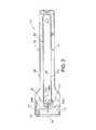
本発明の一実施形態によるガス放電ランプアセンブリが図1と図2に示されており、このアセンブリは全体として番号10で示されている。開示のために、本発明は、2002年4月26日付で出願された標題「誘導駆動ランプアセンブリ」の米国特許出願番号10/133,860に説明されているタイプのような、38ワットで使用するように変換されている従来タイプのPL−S 11ワット紫外線(UV)ランプに関連付けて説明されており、この特許出願の主内容の全体は本明細書に引例として組み入れられている。ランプアセンブリ10は、一般的に、ランプ回路12と外側スリーブ70とを含む。この実施形態では、ランプ回路12は、小直径ワイヤ22のコイルの形であることが好ましい単一の二次コイル14を含む。この二次コイル14は、関連のバラスト(図示していない)の一次コイル(図示していない)から誘導によって電力を受け取る。ランプ回路12全体とランプ18は、外側スリーブ70の内側に完全に収容されている。この図示した実施形態では、外側スリーブ70の少なくとも一部分が透明であり、電気ワイヤまたは他の要素によって貫通されていない。外側スリーブ70が主本体90とキャップ92とを含むことが好ましい。この主本体90は、開いた端部と閉じた端部とを有するおおむね円筒形の管である。ランプ回路12が主本体の中に取り付けられた後に、キャップ92が、ランプ回路12を完全に密封するために主本体90の開いた端部の上に封着される。ランプ18は、チャンバ28を協働的に画定するように相互連結されている2つの互いに平行な脚部72a、72bを有する石英スリーブを備えるおおむね従来通りのPL−Sタイプのランプである。チャンバ28は部分真空状態にされており、水銀蒸気のような所望の放電ガスを収容する。ステム32a、32bが脚部72a、72bの各々の基部に配置されている。1対の従来通りまたは注文設計の電極36a、36bがチャンバ28内に配置されており、それぞれがステム32a、32bの各々の頂部に取り付けられている。この実施形態では、外側スリーブ70が、UV光の効率的な通過を可能にするように石英で作られていることが好ましい。非UV用途では、ランプによって発生させられる熱とランプの動作環境とに部分的に基づいて、外側スリーブがガラス、テフロン、または、プラスチックで作られてもよい。例えば、代案の外側スリーブを、密封された両端部(図示されていない)を有する一定の長さのテフロン管材で作ることが可能である。このテフロン管材をランプアセンブリの残り部分の上に嵌合することが可能であり、その両端部が、そのテフロンスリーブを密封するために圧着し、またはその他の方法で封着することが可能である。テフロン管材の各々の端部を折り返して熱と圧力とを使用して圧着することが好ましい。I. Lamp Configuration A gas discharge lamp assembly according to one embodiment of the present invention is shown in FIGS. 1 and 2, and this assembly is generally designated by the
添付図面、特に図1と図2をさらに参照すると、ランプアセンブリ10は、さらに、外側スリーブ70内にランプ18の両端部を保持する基部50と支持体86とを含む。基部50は、おおむね円筒形であり、外側スリーブ70内にぴったりと嵌合する寸法にされている。基部50は、ランプ18の一方の端部を保持することに加えて、さらに詳細に後述するようにコンデンサ16と磁気スイッチ34とを受ける。さらに詳細に後述するように、基部50は、二次コイル14の巻線を受けるための環状の凹み80と、各脚部72a、72bの基部端部を受けるための1対の穴82a、82bと、コンデンサ16と磁気スイッチ34またはトランスポンダ126とを収容するための1対の隙間84a、84bとを画定する。ランプアセンブリ10は、さらに、二次コイルと電極36a、36bとの間に配置されている熱反射器58を含んでもよい。この熱反射器58は、それが取り付けられている箇所でランプスリーブ52の横断面形状に合致するように形成されていることが好ましく、および、適切な基体上のアルミニウムまたはアルミニウム箔のような従来通りの反射性材料から作られていることが好ましい。支持体86はおおむね円板状の形状であり、外側スリーブ70内にぴったりと嵌合するような寸法にされている。支持体86がランプスリーブ52の脚部72a、72bの間に摩擦嵌合させられるタブ88を含むことが好ましい。基部50と支持体86との精確な設計と形状は、外側スリーブ70とランプ回路12の様々な構成要素との設計および形状にしたがって、用途に応じて様々であることが可能である。基部50と支持体86がセラミックまたは高温度プラスチックのような高温に耐えることが可能な材料で作られていることが好ましい。With further reference to the accompanying drawings, in particular FIGS. 1 and 2, the
誘導ランプアセンブリ10に給電できる様々なバラストが当業者に公知である。したがって、バラストに関しては詳細に説明しない。例示されている実施形態のランプと組み合わせた使用に特に適している1つのバラストが、2002年9月18日付で出願された標題「誘導結合バラスト回路」の米国特許出願番号10/246,155に開示されており、この出願内容の全体が本明細書に引例として組み入れられている。このバラストは、開示されている本発明の実施形態の効率の良い動作を実現するように容易に適合化されることが可能である。 Various ballasts that can power the
II.起動回路
添付図面を参照すると、特に図3と図4において、例示されている実施形態のスタータアセンブリが、上記のUVランプアセンブリとの組合せの形で示されている。ランプ回路12は、電極36a、36bと、コンデンサ16と、二次コイル14と、磁気スイッチ34とから構成されている。本発明の磁気スタータアセンブリと組み合わせた使用に適した1つの典型的なランプ回路が、2002年4月26日付で出願された標題「誘導駆動ランプアセンブリ」の米国特許出願番号10/133,860に説明されている。II. Start-up Circuit Referring to the accompanying drawings, in particular in FIGS. 3 and 4, the illustrated embodiment starter assembly is shown in combination with the UV lamp assembly described above. The
さらに図3と図4を参照すると、磁気スイッチ34は、電極36a、36bの間に直列に接続されており、エレクトロニクスモジュール100によって作動させられる。エレクトロニクスモジュール100は、制御ユニット102と、抵抗器104と、FET 106と、ダイオード108と、電磁石110とによって構成されている。電磁石110は磁気スイッチ34に隣接して配置されており、通電される時に、スイッチ34を選択的に閉じることが可能である。制御ユニット102は電磁石110の動作を制御する。制御ユニット102は、ランプ回路12が給電される度に、一定の時間間隔すなわち「予熱時間」にわたって電磁石110に通電するように、当業で公知の方法を使用してプログラムされている。例示されている実施形態では、ランプバラスト(図示されていない)が一次コイル(図示されていない)から二次コイル14に給電する。ランプバラスト(図示されていない)は、さらに、制御ユニット102にランプ起動信号を与える。その次に、制御ユニット102は、FET 106を閉じるために5ボルト信号を使用し、電磁石110に165ボルトの電圧を生じさせる。この電圧は、磁気スイッチ34を閉じさせる磁界を電磁石110に生じさせ、それによって、二次コイル14からの電流が脚部72a、72bを通過せずに直接的に電極36a、36bを通過して流れることを引き起こす。この結果として、電極36a、36bが急激に加熱される。予熱時間の一定の時間間隔が経過し終わった後に、制御ユニット102はFET 106を開き、電磁石110の電源切断を生じさせる。電磁石110の電源切断はスイッチ34を開き、このことが電極36a、36bの間で脚部72a、72bを通過して電流が流れることを引き起こす。スイッチ34が開くことは、ガス放電ランプ18を起動させるために使用されるランプバラスト(図示されていない)からの電圧サージを生じさせる場合が多い。磁気スイッチ34は、バラスト一次コイル(図示されていない)の磁界によって磁気スイッチ34が動かされないように、そのバラスト一次コイル(図示されていない)の磁界に対して実質的に垂直に配置されていることが好ましい。例示されている実施形態の磁気スイッチ34は、Cotoによって製造されている部品番号RI−48Aの常開磁気リードスイッチ(normally open magnetic reed switch)であるが、当業者は、あらゆる実質的に同様の磁気スイッチが同等に機能するということを理解するであろう。例示されている実施形態のランプアセンブリ10のための予熱時間間隔は400ミリ秒であるが、当業者は、この予熱時間が、異なるランプ構成の間で様々であってよく、および、同一の構成であるランプの間でも様々であってよいということを理解するであろう。例示されている実施形態の電磁石110は、部品番号YT−50054−IのElytoneコイルから構成されている。FETとともに示されているが、当業者は、任意のリレー装置が電磁石110に電力を供給するために使用可能であるということを理解するであろう。例示されている実施形態の制御ユニット102は、部品番号18F452のMicrochip Technology Inc.のマイクロプロセッサから構成されている。 Still referring to FIGS. 3 and 4, the
III.別の実施形態
本発明の磁気スタータアセンブリの別の実施形態は、さらに、無線周波識別(Radio Frequency Identification(RFID))システムも含む。図5を参照すると、例示されている実施形態のランプアセンブリ10は、さらに、トランスポンダ126を有しており、エレクトロニクスモジュール100は、さらに、RFID回路124を有している。RFID回路は当業で公知であり、RFID回路の一例が、「誘導結合バラストを有する水処理システム」の米国特許第6,436,299号に説明されており、この特許の内容の全体が本明細書に引例として組み入れられている。RFID回路は非接触式のデータ読み取りを可能にし、このデータはトランスポンダ126から制御ユニット102に伝送されるか、または、代案の実施形態では、トランスポンダ126と制御ユニット102との間で双方向に伝送される。III. Another Embodiment Another embodiment of the magnetic starter assembly of the present invention further includes a Radio Frequency Identification (RFID) system. Referring to FIG. 5, the
無線周波識別システム124は、UVランプアセンブリ10に固有の情報を得るために制御ユニット102によって使用される。UVランプの無線周波識別トランスポンダ126がUVランプアセンブリ10内に配置されているので、これらの装置は分離されることが無く、このことが制御ユニット102がベースステーション360を経由してトランスポンダ126に対する情報の読取り/書込みを行うことを可能にする。 The radio
再び図5を参照すると、UVランプの無線周波識別トランスポンダ126は、トランスポンダアンテナ362と、読取り/書込みIDIC(R)(e5551)チップ364とを含む。読取り/書込みIDIC(R)(e5551)チップは、さらに、それぞれのUVランプアセンブリ10に関する関連情報を記憶場所内に物理的に記憶するEEPROMデバイス366を含む。この現時点で好ましい実施形態では、この関連情報は紫外線ランプのシリアル番号と紫外線ランプの予熱時間とから成る。 Referring again to FIG. 5, the UV lamp radio
紫外線ランプのシリアル番号は、各々の紫外線ランプアセンブリ10に固有である。紫外線ランプの予熱時間は、紫外線ランプ18の予熱に必要とされる時間の量に関係する。 The UV lamp serial number is unique to each
無線周波識別システム124は、図5に示されるように電気的に接続されている、ベースステーション360と、コイル380と、複数のダイオード382、384、386、388、390、392、394と、複数の抵抗器396、398、400、402、404、406、408、410、412、414、416、418、420と、複数のコンデンサ422、424、426、428、430、432、434、436を含む。当業者は、上述の構成要素の接続が当業者に公知であることを理解するであろう。無線周波識別システム124は、TK5551A−PPに関して説明した仕様を使用するエレクトロニクスモジュール100の中に収容されており、このTK5551A−PPは、上述したようにTEMIC Semiconductorsによって製造されている。本発明のためには、ベースステーション360が紫外光無線周波識別トランスポンダ126との双方向通信のためにコイル380を使用するということを指摘することが重要である。制御ユニット102は、その制御ユニット102がベースステーション360と通信することが可能であるようにベースステーション360と電気的に接続されている。無線周波識別システム124は、図5に示されているように、第1の直流電源180と第2の直流電源184とに接続されており、この第2の直流電源184は、動作中に機能するように無線周波識別システム124にエネルギーを供給する。 The radio
例示されている実施形態の1つの代案では、EEPROMデバイス366内に格納されている 当業で公知の方法を使用してランプアセンブリ10のシリアル番号を用いてプログラムされている。ランプアセンブリ10の起動時に、無線周波識別システム124は、トランスポンダ126からランプアセンブリ10に関するシリアル番号を引き出す。ランプアセンブリ10のシリアル番号はベースステーション360によって制御ユニット102に通信される。その次に、当業で公知の方法を使用することによって、制御ユニット102は、トランスポンダ126からの引き出されたシリアル番号に基づいてその特定のランプアセンブリに関する予熱時間を求めるために、予めプログラムされたルックアップテーブルを参照する。制御ユニット102は、特定された予熱時間にわたって電磁石110を作動させ、それによってランプアセンブリ10を起動させる前に要素36a、36bを予熱する。 In one alternative of the illustrated embodiment, it is programmed with the serial number of the
例示されている実施形態の第2の代案では、EEPROMデバイス366内に格納されている 当業で公知の方法を使用してランプアセンブリ10のシリアル番号を用いてプログラムされている。EEPROMデバイス366は、さらに、本発明のスタータアセンブリによって起動させられた各ランプアセンブリ10の起動の数を記憶するように構成されている。ランプアセンブリ10の起動時には、無線周波識別システム124が、ランプアセンブリ10に関するシリアル番号をトランスポンダ126から引き出す。ランプアセンブリ10のシリアル番号はベースステーション360によって制御ユニット10に通信される。その次に、制御ユニット102は、ランプアセンブリ10のシリアル番号とランプアセンブリ10の起動の合計数とに基づいて、その特定のガス放電ランプアセンブリ10に関する予熱時間を求めるために、EEPROMデバイス366内に記憶されている予めプログラムされたルックアップテーブルを参照する。ランプアセンブリ10が起動された後に、制御ユニットは、EEPROMデバイス366内に記憶されている記憶されているランプアセンブリ10の起動の合計数を増やす。本発明の一実施形態では、ランプアセンブリ10の予熱時間が起動数の増大につれて増大させられる。 In a second alternative of the illustrated embodiment, it is programmed with the serial number of the
別の代案の実施形態では、EEPROMデバイス366内に格納されている 当業で公知の方法を使用してランプアセンブリ19の予熱を用いてプログラムされている。ランプアセンブリ10の起動時に、無線周波識別システム124は、EPROMデバイス366内に格納されているものからランプアセンブリ10に関する予熱を引き出す。ランプアセンブリ10の予熱は、ベースステーション360によって制御ユニット102に伝達される。その次に、制御ユニット102は、ランプ回路12が電源投入される度に電磁石110に通電するために、この予熱時間を使用する。 In another alternative embodiment, the lamp assembly 19 is programmed with preheating using methods known in the art that are stored in the
当業者は、接触タイプの識別システムのような他の識別システムが本発明と組み合わせて使用可能であることを理解するであろう。しかし、本発明のこの好ましい実施形態は、無線周波識別システム124がもたらす特有の利点のために、無線周波識別システム124を使用する。 One skilled in the art will appreciate that other identification systems, such as contact type identification systems, can be used in conjunction with the present invention. However, this preferred embodiment of the present invention uses the radio
磁気スタータアセンブリの構成は、主としてランプのタイプとこれに関連した電力要件とに応じて、用途毎に様々であってよい。本発明は、様々な既存の照明システムと組み合わせた使用を可能にするために、容易に変更されることが可能である。上述の説明は、本発明の様々な実施形態の説明である。様々な変更と変形とが、添付された特許請求項に定義されている通りの本発明の着想と広範な側面とから逸脱することなしに加えられることが可能であり、こうした変更と変形は均等の原則を含む特許法の原理にしたがって解釈されなければならない。例えば、冠詞「a」、「an」、「the」または「said」を使用して単数の形で特許請求項の要素を言及することが、その要素を単数に限定するものとして理解されてはならない。 The configuration of the magnetic starter assembly may vary from application to application, primarily depending on the type of lamp and the associated power requirements. The present invention can be easily modified to allow use in combination with various existing lighting systems. The above description is that of various embodiments of the invention. Various changes and modifications can be made without departing from the spirit and broad aspects of the invention as defined in the appended claims, and such changes and modifications are equally Must be interpreted in accordance with the principles of patent law, including For example, referring to an element of a claim in the singular using the articles “a”, “an”, “the”, or “said” is not to be understood as limiting that element to the singular. Don't be.
Claims (9)
Translated fromJapanese前記ガス放電ランプの少なくとも2つの電極の間に直列に配置されている少なくとも1つのスイッチと、
前記スイッチを作動させるように動作する制御ユニットと、
前記制御ユニットに電気的に接続されているベースステーションと、
前記ベースステーションと無線通信している前記ガス放電ランプアセンブリ内に配置されている少なくとも1つの無線周波識別トランスポンダと、
を含み、
前記制御ユニットは、前記トランスポンダから受け取られた情報にしたがって前記スイッチを作動させるスタータアセンブリ。A starter assembly for a gas discharge lamp assembly,
At least one switch arranged in series between at least two electrodes of the gas discharge lamp;
A control unit that operates to actuate the switch;
A base station electrically connected to the control unit;
At least one radio frequency identification transponder disposed in the gas discharge lamp assembly in wireless communication with the base station;
Including
A starter assembly in which the control unit activates the switch in accordance with information received from the transponder.
常開磁気スイッチを前記ガス放電ランプの少なくとも2つの電極に直列に接続する段階、
電流が通常前記ガス放電ランプに向かう段階、
予め決められた長さの時間にわたって電磁石によって前記磁気スイッチを閉じる段階、
前記予め決められた長さの時間にわたって前記電極と前記磁気スイッチとを選択的に通る電流を供給する段階、
とを含み、
さらに、前記ガス放電ランプ内に配置されているトランスポンダから予熱に関する情報を引き出し、該情報に基づき前記磁気スイッチを作動させる段階を含む方法。A method of starting a gas discharge lamp, comprising:
Connecting a normally open magnetic switch in series with at least two electrodes of the gas discharge lamp;
A stage in which current is normally directed to the gas discharge lamp;
Closing the magnetic switch with an electromagnet for a predetermined length of time;
Supplying a current selectively through the electrode and the magnetic switch for the predetermined amount of time;
Including
The method furtherincludes extracting information regarding preheating from a transponder disposed in the gas discharge lampand activating the magnetic switch based on the information .
Applications Claiming Priority (2)
| Application Number | Priority Date | Filing Date | Title |
|---|---|---|---|
| US35790802P | 2002-02-19 | 2002-02-19 | |
| PCT/US2003/004768WO2003071568A2 (en) | 2002-02-19 | 2003-02-18 | Starter assembly for a gas discharge lamp |
Publications (2)
| Publication Number | Publication Date |
|---|---|
| JP2005527070A JP2005527070A (en) | 2005-09-08 |
| JP4358635B2true JP4358635B2 (en) | 2009-11-04 |
Family
ID=27757673
Family Applications (2)
| Application Number | Title | Priority Date | Filing Date |
|---|---|---|---|
| JP2003570378AExpired - LifetimeJP4358635B2 (en) | 2002-02-19 | 2003-02-18 | Starter assembly for gas discharge lamp |
| JP2003569304AExpired - LifetimeJP4430399B2 (en) | 2002-02-19 | 2003-02-18 | Detachable closure assembly for water purification equipment |
Family Applications After (1)
| Application Number | Title | Priority Date | Filing Date |
|---|---|---|---|
| JP2003569304AExpired - LifetimeJP4430399B2 (en) | 2002-02-19 | 2003-02-18 | Detachable closure assembly for water purification equipment |
Country Status (9)
| Country | Link |
|---|---|
| US (3) | US6984320B2 (en) |
| EP (2) | EP1476239A4 (en) |
| JP (2) | JP4358635B2 (en) |
| KR (2) | KR100824147B1 (en) |
| CN (3) | CN100354023C (en) |
| AU (2) | AU2003215277B2 (en) |
| CA (2) | CA2475118C (en) |
| NZ (2) | NZ534331A (en) |
| WO (2) | WO2003070352A1 (en) |
Families Citing this family (172)
| Publication number | Priority date | Publication date | Assignee | Title |
|---|---|---|---|---|
| US7065658B1 (en) | 2001-05-18 | 2006-06-20 | Palm, Incorporated | Method and apparatus for synchronizing and recharging a connector-less portable computer system |
| WO2005027588A1 (en)* | 2003-09-18 | 2005-03-24 | Philips Intellectual Property & Standards Gmbh | Blended light lamp |
| US8280398B2 (en)* | 2004-03-03 | 2012-10-02 | Nec Corporation | Positioning system, positioning method, and program thereof |
| DE102004039677B4 (en) | 2004-05-28 | 2023-02-02 | Zumtobel Lighting Gmbh | Building management system and actuator with memory part |
| DE102004029225A1 (en)* | 2004-06-17 | 2006-01-12 | Hydac Filtertechnik Gmbh | Filter device and filter element |
| DE102004031608A1 (en)* | 2004-06-30 | 2006-02-09 | Mann + Hummel Gmbh | housing lock |
| DE102004038512A1 (en)* | 2004-08-07 | 2006-03-30 | Scherle, Jürgen, Dipl.-Ing. (FH) | Lamps and/or lights monitoring method for industrial application, involves selecting data from memory, and conveying data to computer, while inserting ID-chip and reading data by manufacturer and user, where data is evaluated in computer |
| US20060272997A1 (en)* | 2005-06-06 | 2006-12-07 | Hsin-Fa Liu | Reverse osmosis filtering assembly |
| US7825543B2 (en)* | 2005-07-12 | 2010-11-02 | Massachusetts Institute Of Technology | Wireless energy transfer |
| CN101860089B (en) | 2005-07-12 | 2013-02-06 | 麻省理工学院 | wireless non-radiative energy transfer |
| JP4813171B2 (en)* | 2005-12-16 | 2011-11-09 | 株式会社豊田自動織機 | Stator manufacturing method and manufacturing apparatus |
| US7952322B2 (en) | 2006-01-31 | 2011-05-31 | Mojo Mobility, Inc. | Inductive power source and charging system |
| US11201500B2 (en) | 2006-01-31 | 2021-12-14 | Mojo Mobility, Inc. | Efficiencies and flexibilities in inductive (wireless) charging |
| US8169185B2 (en) | 2006-01-31 | 2012-05-01 | Mojo Mobility, Inc. | System and method for inductive charging of portable devices |
| US8337693B2 (en)* | 2006-03-10 | 2012-12-25 | Whirlpool Corporation | Enhanced filter indicatior for refrigerator |
| US11329511B2 (en) | 2006-06-01 | 2022-05-10 | Mojo Mobility Inc. | Power source, charging system, and inductive receiver for mobile devices |
| US7948208B2 (en)* | 2006-06-01 | 2011-05-24 | Mojo Mobility, Inc. | Power source, charging system, and inductive receiver for mobile devices |
| CN105323942A (en)* | 2006-06-02 | 2016-02-10 | 皇家飞利浦电子股份有限公司 | Lamp control circuit and method of driving lamp |
| KR20090024809A (en) | 2006-06-27 | 2009-03-09 | 코닌클리케 필립스 일렉트로닉스 엔.브이. | Water purification system and filter element for this system |
| US9022293B2 (en) | 2006-08-31 | 2015-05-05 | Semiconductor Energy Laboratory Co., Ltd. | Semiconductor device and power receiving device |
| US7560867B2 (en)* | 2006-10-17 | 2009-07-14 | Access Business Group International, Llc | Starter for a gas discharge light source |
| US20080156717A1 (en)* | 2006-12-07 | 2008-07-03 | Access Business Group International Llc | Fluid flow director for water treatment system |
| MY147309A (en)* | 2007-01-08 | 2012-11-30 | Access Business Group Int Llc | Inductively-powered gas discharge lamp circuit |
| US7821208B2 (en)* | 2007-01-08 | 2010-10-26 | Access Business Group International Llc | Inductively-powered gas discharge lamp circuit |
| KR100841572B1 (en)* | 2007-03-05 | 2008-06-26 | 최인실 | Magnetic ballast |
| KR20080083903A (en)* | 2007-03-13 | 2008-09-19 | 삼성전자주식회사 | Water Purifier |
| EP2132961B1 (en)* | 2007-03-27 | 2021-05-12 | Signify Holding B.V. | Control circuit, system for operating a device and device for programming such a control circuit |
| US8115448B2 (en) | 2007-06-01 | 2012-02-14 | Michael Sasha John | Systems and methods for wireless power |
| US9421388B2 (en) | 2007-06-01 | 2016-08-23 | Witricity Corporation | Power generation for implantable devices |
| US7883619B2 (en)* | 2007-11-13 | 2011-02-08 | Access Business Group International Llc | Water treatment system with moisture detector |
| JP2011512621A (en)* | 2008-02-14 | 2011-04-21 | コーニンクレッカ フィリップス エレクトロニクス エヌ ヴィ | Control device for controlling the discharge lamp |
| US20110050164A1 (en) | 2008-05-07 | 2011-03-03 | Afshin Partovi | System and methods for inductive charging, and improvements and uses thereof |
| CN102099958B (en) | 2008-05-14 | 2013-12-25 | 麻省理工学院 | Wireless power transfer including interference enhancement |
| TW200948451A (en)* | 2008-05-20 | 2009-12-01 | Zhi-Hao Cai | Water treatment device featuring easy replacement of filter |
| US20090289582A1 (en)* | 2008-05-23 | 2009-11-26 | Nordson Corporation | Lamp assemblies, lamp systems, and methods of operating lamp systems |
| USD640976S1 (en) | 2008-08-28 | 2011-07-05 | Hewlett-Packard Development Company, L.P. | Support structure and/or cradle for a mobile computing device |
| US8527688B2 (en) | 2008-09-26 | 2013-09-03 | Palm, Inc. | Extending device functionality amongst inductively linked devices |
| US8401469B2 (en)* | 2008-09-26 | 2013-03-19 | Hewlett-Packard Development Company, L.P. | Shield for use with a computing device that receives an inductive signal transmission |
| US8385822B2 (en) | 2008-09-26 | 2013-02-26 | Hewlett-Packard Development Company, L.P. | Orientation and presence detection for use in configuring operations of computing devices in docked environments |
| US8868939B2 (en) | 2008-09-26 | 2014-10-21 | Qualcomm Incorporated | Portable power supply device with outlet connector |
| US8234509B2 (en)* | 2008-09-26 | 2012-07-31 | Hewlett-Packard Development Company, L.P. | Portable power supply device for mobile computing devices |
| US8850045B2 (en) | 2008-09-26 | 2014-09-30 | Qualcomm Incorporated | System and method for linking and sharing resources amongst devices |
| US8688037B2 (en)* | 2008-09-26 | 2014-04-01 | Hewlett-Packard Development Company, L.P. | Magnetic latching mechanism for use in mating a mobile computing device to an accessory device |
| US8712324B2 (en) | 2008-09-26 | 2014-04-29 | Qualcomm Incorporated | Inductive signal transfer system for computing devices |
| US8629578B2 (en) | 2008-09-27 | 2014-01-14 | Witricity Corporation | Wireless energy transfer systems |
| US8552592B2 (en) | 2008-09-27 | 2013-10-08 | Witricity Corporation | Wireless energy transfer with feedback control for lighting applications |
| US8907531B2 (en) | 2008-09-27 | 2014-12-09 | Witricity Corporation | Wireless energy transfer with variable size resonators for medical applications |
| US9515494B2 (en) | 2008-09-27 | 2016-12-06 | Witricity Corporation | Wireless power system including impedance matching network |
| US8461720B2 (en) | 2008-09-27 | 2013-06-11 | Witricity Corporation | Wireless energy transfer using conducting surfaces to shape fields and reduce loss |
| US9601261B2 (en) | 2008-09-27 | 2017-03-21 | Witricity Corporation | Wireless energy transfer using repeater resonators |
| US9544683B2 (en) | 2008-09-27 | 2017-01-10 | Witricity Corporation | Wirelessly powered audio devices |
| US9601266B2 (en) | 2008-09-27 | 2017-03-21 | Witricity Corporation | Multiple connected resonators with a single electronic circuit |
| US8461722B2 (en) | 2008-09-27 | 2013-06-11 | Witricity Corporation | Wireless energy transfer using conducting surfaces to shape field and improve K |
| US8901779B2 (en) | 2008-09-27 | 2014-12-02 | Witricity Corporation | Wireless energy transfer with resonator arrays for medical applications |
| US8901778B2 (en) | 2008-09-27 | 2014-12-02 | Witricity Corporation | Wireless energy transfer with variable size resonators for implanted medical devices |
| US8304935B2 (en) | 2008-09-27 | 2012-11-06 | Witricity Corporation | Wireless energy transfer using field shaping to reduce loss |
| US9184595B2 (en) | 2008-09-27 | 2015-11-10 | Witricity Corporation | Wireless energy transfer in lossy environments |
| EP3179640A1 (en) | 2008-09-27 | 2017-06-14 | WiTricity Corporation | Wireless energy transfer systems |
| US8937408B2 (en) | 2008-09-27 | 2015-01-20 | Witricity Corporation | Wireless energy transfer for medical applications |
| US8692410B2 (en) | 2008-09-27 | 2014-04-08 | Witricity Corporation | Wireless energy transfer with frequency hopping |
| US8476788B2 (en) | 2008-09-27 | 2013-07-02 | Witricity Corporation | Wireless energy transfer with high-Q resonators using field shaping to improve K |
| US8587153B2 (en) | 2008-09-27 | 2013-11-19 | Witricity Corporation | Wireless energy transfer using high Q resonators for lighting applications |
| US9601270B2 (en) | 2008-09-27 | 2017-03-21 | Witricity Corporation | Low AC resistance conductor designs |
| US9093853B2 (en) | 2008-09-27 | 2015-07-28 | Witricity Corporation | Flexible resonator attachment |
| US9396867B2 (en) | 2008-09-27 | 2016-07-19 | Witricity Corporation | Integrated resonator-shield structures |
| US8461721B2 (en) | 2008-09-27 | 2013-06-11 | Witricity Corporation | Wireless energy transfer using object positioning for low loss |
| US8946938B2 (en) | 2008-09-27 | 2015-02-03 | Witricity Corporation | Safety systems for wireless energy transfer in vehicle applications |
| US8482158B2 (en) | 2008-09-27 | 2013-07-09 | Witricity Corporation | Wireless energy transfer using variable size resonators and system monitoring |
| US9065423B2 (en) | 2008-09-27 | 2015-06-23 | Witricity Corporation | Wireless energy distribution system |
| US8723366B2 (en) | 2008-09-27 | 2014-05-13 | Witricity Corporation | Wireless energy transfer resonator enclosures |
| US8441154B2 (en) | 2008-09-27 | 2013-05-14 | Witricity Corporation | Multi-resonator wireless energy transfer for exterior lighting |
| US8587155B2 (en) | 2008-09-27 | 2013-11-19 | Witricity Corporation | Wireless energy transfer using repeater resonators |
| US8963488B2 (en) | 2008-09-27 | 2015-02-24 | Witricity Corporation | Position insensitive wireless charging |
| US8324759B2 (en) | 2008-09-27 | 2012-12-04 | Witricity Corporation | Wireless energy transfer using magnetic materials to shape field and reduce loss |
| US8692412B2 (en) | 2008-09-27 | 2014-04-08 | Witricity Corporation | Temperature compensation in a wireless transfer system |
| US8487480B1 (en) | 2008-09-27 | 2013-07-16 | Witricity Corporation | Wireless energy transfer resonator kit |
| US8922066B2 (en) | 2008-09-27 | 2014-12-30 | Witricity Corporation | Wireless energy transfer with multi resonator arrays for vehicle applications |
| US8686598B2 (en) | 2008-09-27 | 2014-04-01 | Witricity Corporation | Wireless energy transfer for supplying power and heat to a device |
| US9035499B2 (en) | 2008-09-27 | 2015-05-19 | Witricity Corporation | Wireless energy transfer for photovoltaic panels |
| US9106203B2 (en) | 2008-09-27 | 2015-08-11 | Witricity Corporation | Secure wireless energy transfer in medical applications |
| US8928276B2 (en) | 2008-09-27 | 2015-01-06 | Witricity Corporation | Integrated repeaters for cell phone applications |
| US8466583B2 (en) | 2008-09-27 | 2013-06-18 | Witricity Corporation | Tunable wireless energy transfer for outdoor lighting applications |
| US8669676B2 (en) | 2008-09-27 | 2014-03-11 | Witricity Corporation | Wireless energy transfer across variable distances using field shaping with magnetic materials to improve the coupling factor |
| US8772973B2 (en) | 2008-09-27 | 2014-07-08 | Witricity Corporation | Integrated resonator-shield structures |
| US9577436B2 (en) | 2008-09-27 | 2017-02-21 | Witricity Corporation | Wireless energy transfer for implantable devices |
| US8933594B2 (en) | 2008-09-27 | 2015-01-13 | Witricity Corporation | Wireless energy transfer for vehicles |
| US8497601B2 (en) | 2008-09-27 | 2013-07-30 | Witricity Corporation | Wireless energy transfer converters |
| US8569914B2 (en) | 2008-09-27 | 2013-10-29 | Witricity Corporation | Wireless energy transfer using object positioning for improved k |
| US8912687B2 (en) | 2008-09-27 | 2014-12-16 | Witricity Corporation | Secure wireless energy transfer for vehicle applications |
| US8947186B2 (en) | 2008-09-27 | 2015-02-03 | Witricity Corporation | Wireless energy transfer resonator thermal management |
| US9246336B2 (en) | 2008-09-27 | 2016-01-26 | Witricity Corporation | Resonator optimizations for wireless energy transfer |
| US9318922B2 (en) | 2008-09-27 | 2016-04-19 | Witricity Corporation | Mechanically removable wireless power vehicle seat assembly |
| US8957549B2 (en) | 2008-09-27 | 2015-02-17 | Witricity Corporation | Tunable wireless energy transfer for in-vehicle applications |
| US9744858B2 (en) | 2008-09-27 | 2017-08-29 | Witricity Corporation | System for wireless energy distribution in a vehicle |
| US8643326B2 (en) | 2008-09-27 | 2014-02-04 | Witricity Corporation | Tunable wireless energy transfer systems |
| US9160203B2 (en) | 2008-09-27 | 2015-10-13 | Witricity Corporation | Wireless powered television |
| US8400017B2 (en) | 2008-09-27 | 2013-03-19 | Witricity Corporation | Wireless energy transfer for computer peripheral applications |
| US8410636B2 (en) | 2008-09-27 | 2013-04-02 | Witricity Corporation | Low AC resistance conductor designs |
| US9105959B2 (en) | 2008-09-27 | 2015-08-11 | Witricity Corporation | Resonator enclosure |
| US8471410B2 (en) | 2008-09-27 | 2013-06-25 | Witricity Corporation | Wireless energy transfer over distance using field shaping to improve the coupling factor |
| US8598743B2 (en) | 2008-09-27 | 2013-12-03 | Witricity Corporation | Resonator arrays for wireless energy transfer |
| US8362651B2 (en) | 2008-10-01 | 2013-01-29 | Massachusetts Institute Of Technology | Efficient near-field wireless energy transfer using adiabatic system variations |
| US9083686B2 (en)* | 2008-11-12 | 2015-07-14 | Qualcomm Incorporated | Protocol for program during startup sequence |
| WO2010078557A2 (en) | 2009-01-05 | 2010-07-08 | Palm, Inc. | Interior connector scheme for accessorizing a mobile computing device with a removeable housing segment |
| CN104692570A (en)* | 2009-01-12 | 2015-06-10 | 捷通国际有限公司 | Point-of-use water treatment system |
| WO2010121964A1 (en)* | 2009-04-24 | 2010-10-28 | Osram Gesellschaft mit beschränkter Haftung | Lamp-coupler-unit for electrodeless high intensity discharge (ehid) lamps with a data memory and communication and an impedance-controlled feedthrough and electrodeless high intensity discharge system with such lamp-coupler-unit |
| DE102009019625B4 (en)* | 2009-04-30 | 2014-05-15 | Osram Gmbh | A method of determining a type of gas discharge lamp and electronic ballast for operating at least two different types of gas discharge lamps |
| US8437695B2 (en)* | 2009-07-21 | 2013-05-07 | Hewlett-Packard Development Company, L.P. | Power bridge circuit for bi-directional inductive signaling |
| US9395827B2 (en)* | 2009-07-21 | 2016-07-19 | Qualcomm Incorporated | System for detecting orientation of magnetically coupled devices |
| US8954001B2 (en)* | 2009-07-21 | 2015-02-10 | Qualcomm Incorporated | Power bridge circuit for bi-directional wireless power transmission |
| US8755815B2 (en) | 2010-08-31 | 2014-06-17 | Qualcomm Incorporated | Use of wireless access point ID for position determination |
| US8395547B2 (en) | 2009-08-27 | 2013-03-12 | Hewlett-Packard Development Company, L.P. | Location tracking for mobile computing device |
| JP5564880B2 (en)* | 2009-10-02 | 2014-08-06 | ウシオ電機株式会社 | UV irradiation equipment |
| US8022775B2 (en) | 2009-10-08 | 2011-09-20 | Etymotic Research, Inc. | Systems and methods for maintaining a drive signal to a resonant circuit at a resonant frequency |
| US8237402B2 (en) | 2009-10-08 | 2012-08-07 | Etymotic Research, Inc. | Magnetically coupled battery charging system |
| US8460816B2 (en) | 2009-10-08 | 2013-06-11 | Etymotic Research, Inc. | Rechargeable battery assemblies and methods of constructing rechargeable battery assemblies |
| US8174234B2 (en)* | 2009-10-08 | 2012-05-08 | Etymotic Research, Inc. | Magnetically coupled battery charging system |
| US8174233B2 (en) | 2009-10-08 | 2012-05-08 | Etymotic Research, Inc. | Magnetically coupled battery charging system |
| USD674391S1 (en) | 2009-11-17 | 2013-01-15 | Hewlett-Packard Development Company, L.P. | Docking station for a computing device |
| KR101795827B1 (en)* | 2010-06-04 | 2017-11-08 | 액세스 비지니스 그룹 인터내셔날 엘엘씨 | Wirelessly powered dielectric barrier discharge lamp, and base station for a wirelessly powered fluid treatment system |
| WO2011156768A2 (en) | 2010-06-11 | 2011-12-15 | Mojo Mobility, Inc. | System for wireless power transfer that supports interoperability, and multi-pole magnets for use therewith |
| USD643506S1 (en) | 2010-07-07 | 2011-08-16 | Access Business Group International Llc | Water treatment system |
| KR101747085B1 (en)* | 2010-08-06 | 2017-06-27 | 제너럴 이콜로지 인코포레이티드 | Apparatus for filtering and/or conditioning and/or purifying a fluid such as water |
| US9602168B2 (en) | 2010-08-31 | 2017-03-21 | Witricity Corporation | Communication in wireless energy transfer systems |
| CN103222319B (en) | 2010-09-29 | 2016-08-10 | 高通股份有限公司 | A kind of method for mobile computing device and mobile computing device |
| US10115520B2 (en) | 2011-01-18 | 2018-10-30 | Mojo Mobility, Inc. | Systems and method for wireless power transfer |
| US11342777B2 (en) | 2011-01-18 | 2022-05-24 | Mojo Mobility, Inc. | Powering and/or charging with more than one protocol |
| US9178369B2 (en) | 2011-01-18 | 2015-11-03 | Mojo Mobility, Inc. | Systems and methods for providing positioning freedom, and support of different voltages, protocols, and power levels in a wireless power system |
| US9496732B2 (en) | 2011-01-18 | 2016-11-15 | Mojo Mobility, Inc. | Systems and methods for wireless power transfer |
| WO2012141992A1 (en)* | 2011-04-15 | 2012-10-18 | Boyle William P | Apparatus for sterilizing the inside of a container |
| US9948145B2 (en) | 2011-07-08 | 2018-04-17 | Witricity Corporation | Wireless power transfer for a seat-vest-helmet system |
| CN108110907B (en) | 2011-08-04 | 2022-08-02 | 韦特里西提公司 | Tunable wireless power supply architecture |
| US20130048550A1 (en)* | 2011-08-22 | 2013-02-28 | Access Business Group International Llc | Water treatment system with sealing enclosure |
| EP2754222B1 (en) | 2011-09-09 | 2015-11-18 | Witricity Corporation | Foreign object detection in wireless energy transfer systems |
| US20130062966A1 (en) | 2011-09-12 | 2013-03-14 | Witricity Corporation | Reconfigurable control architectures and algorithms for electric vehicle wireless energy transfer systems |
| US9318257B2 (en) | 2011-10-18 | 2016-04-19 | Witricity Corporation | Wireless energy transfer for packaging |
| CA2853824A1 (en) | 2011-11-04 | 2013-05-10 | Witricity Corporation | Wireless energy transfer modeling tool |
| JP2015508987A (en) | 2012-01-26 | 2015-03-23 | ワイトリシティ コーポレーションWitricity Corporation | Wireless energy transmission with reduced field |
| US9722447B2 (en) | 2012-03-21 | 2017-08-01 | Mojo Mobility, Inc. | System and method for charging or powering devices, such as robots, electric vehicles, or other mobile devices or equipment |
| US20130271069A1 (en) | 2012-03-21 | 2013-10-17 | Mojo Mobility, Inc. | Systems and methods for wireless power transfer |
| US9343922B2 (en) | 2012-06-27 | 2016-05-17 | Witricity Corporation | Wireless energy transfer for rechargeable batteries |
| US9287607B2 (en) | 2012-07-31 | 2016-03-15 | Witricity Corporation | Resonator fine tuning |
| US9595378B2 (en) | 2012-09-19 | 2017-03-14 | Witricity Corporation | Resonator enclosure |
| EP2909912B1 (en) | 2012-10-19 | 2022-08-10 | WiTricity Corporation | Foreign object detection in wireless energy transfer systems |
| US9842684B2 (en) | 2012-11-16 | 2017-12-12 | Witricity Corporation | Systems and methods for wireless power system with improved performance and/or ease of use |
| US9837846B2 (en) | 2013-04-12 | 2017-12-05 | Mojo Mobility, Inc. | System and method for powering or charging receivers or devices having small surface areas or volumes |
| US9857821B2 (en) | 2013-08-14 | 2018-01-02 | Witricity Corporation | Wireless power transfer frequency adjustment |
| EP2846147B1 (en)* | 2013-09-06 | 2020-01-01 | Atlas Material Testing Technology GmbH | Weathering Test using radiation source identifiable by a RFID chip |
| US9780573B2 (en) | 2014-02-03 | 2017-10-03 | Witricity Corporation | Wirelessly charged battery system |
| US9952266B2 (en) | 2014-02-14 | 2018-04-24 | Witricity Corporation | Object detection for wireless energy transfer systems |
| US9892849B2 (en) | 2014-04-17 | 2018-02-13 | Witricity Corporation | Wireless power transfer systems with shield openings |
| US9842687B2 (en) | 2014-04-17 | 2017-12-12 | Witricity Corporation | Wireless power transfer systems with shaped magnetic components |
| US9837860B2 (en) | 2014-05-05 | 2017-12-05 | Witricity Corporation | Wireless power transmission systems for elevators |
| JP2017518018A (en) | 2014-05-07 | 2017-06-29 | ワイトリシティ コーポレーションWitricity Corporation | Foreign object detection in wireless energy transmission systems |
| US9954375B2 (en) | 2014-06-20 | 2018-04-24 | Witricity Corporation | Wireless power transfer systems for surfaces |
| US10574091B2 (en) | 2014-07-08 | 2020-02-25 | Witricity Corporation | Enclosures for high power wireless power transfer systems |
| CN107258046B (en) | 2014-07-08 | 2020-07-17 | 无线电力公司 | Resonator equalization in wireless power transfer systems |
| US9843217B2 (en) | 2015-01-05 | 2017-12-12 | Witricity Corporation | Wireless energy transfer for wearables |
| BR112017022999A2 (en)* | 2015-05-22 | 2018-07-24 | Access Business Group Int Llc | point of use water treatment system |
| US10248899B2 (en) | 2015-10-06 | 2019-04-02 | Witricity Corporation | RFID tag and transponder detection in wireless energy transfer systems |
| US9929721B2 (en) | 2015-10-14 | 2018-03-27 | Witricity Corporation | Phase and amplitude detection in wireless energy transfer systems |
| WO2017070227A1 (en) | 2015-10-19 | 2017-04-27 | Witricity Corporation | Foreign object detection in wireless energy transfer systems |
| WO2017070009A1 (en) | 2015-10-22 | 2017-04-27 | Witricity Corporation | Dynamic tuning in wireless energy transfer systems |
| US10075019B2 (en) | 2015-11-20 | 2018-09-11 | Witricity Corporation | Voltage source isolation in wireless power transfer systems |
| WO2017136491A1 (en) | 2016-02-02 | 2017-08-10 | Witricity Corporation | Controlling wireless power transfer systems |
| CN114123540B (en) | 2016-02-08 | 2024-08-20 | 韦特里西提公司 | Variable capacitance device and high-power wireless energy transmission system |
| WO2019006376A1 (en) | 2017-06-29 | 2019-01-03 | Witricity Corporation | Protection and control of wireless power systems |
| PL234666B1 (en)* | 2018-04-26 | 2020-03-31 | Aquael Janusz Jankiewicz Spolka Z Ograniczona Odpowiedzialnoscia | Water filter for an aquarium |
| US11383183B2 (en) | 2018-10-05 | 2022-07-12 | Pureflo Limited | Cap for refillable water filter |
| US11444485B2 (en) | 2019-02-05 | 2022-09-13 | Mojo Mobility, Inc. | Inductive charging system with charging electronics physically separated from charging coil |
| KR102816226B1 (en) | 2019-04-11 | 2025-06-05 | 삼성전자주식회사 | Filter assembly for water purifier |
| US12024039B2 (en) | 2021-12-07 | 2024-07-02 | Arnold Chase | Vehicle self-centered charging system |
Family Cites Families (56)
| Publication number | Priority date | Publication date | Assignee | Title |
|---|---|---|---|---|
| US1108765A (en)* | 1912-08-08 | 1914-08-25 | Michael J Lawless | Cover-fastening device for receptacles. |
| US1370007A (en)* | 1919-01-13 | 1921-03-01 | Jr Augustine Davis | Milk-can |
| US1760888A (en)* | 1927-08-05 | 1930-06-03 | Augustine Davis Jr | Lock cover for cans |
| US2779616A (en)* | 1954-12-10 | 1957-01-29 | Daniel E Houghton | Cam closure |
| US2916671A (en)* | 1958-06-06 | 1959-12-08 | Westinghouse Electric Corp | Starting and operating circuit for gaseous discharge lamps |
| US3394836A (en)* | 1966-01-28 | 1968-07-30 | George L Fowler | Fill tube cap |
| US3640390A (en) | 1968-05-13 | 1972-02-08 | Torite Enterprises Inc | Replaceable cartridge filter housing |
| US3746171A (en) | 1971-07-21 | 1973-07-17 | J Thomsen | Filter assembly |
| US3949787A (en)* | 1974-10-21 | 1976-04-13 | Universal Valve Company, Inc. | Pipe cap |
| US4328446A (en)* | 1980-04-11 | 1982-05-04 | Gte Laboratories Incorporated | Method and apparatus for starting high intensity discharge lamps |
| US4371439A (en) | 1980-05-08 | 1983-02-01 | Fram Corporation | Cam actuated filter assembly |
| US4349768A (en)* | 1980-06-26 | 1982-09-14 | Creators, Inc. | Method for starting and operating a preheat type fluorescent lamp |
| US4355261A (en) | 1980-12-15 | 1982-10-19 | Gte Products Corporation | Discharge lamp with integral starter |
| JPS5935354A (en)* | 1982-08-23 | 1984-02-27 | Iwasaki Electric Co Ltd | high pressure metal vapor discharge lamp |
| US4501994A (en)* | 1982-09-02 | 1985-02-26 | Cooper Industries, Inc. | Ballast modifying device and lead-type ballast for programming and controlling the operating performance of an hid sodium lamp |
| US4523795A (en)* | 1982-09-30 | 1985-06-18 | Gte Products Corporation | Discharge lamp operating apparatus and method |
| JPS59198699A (en)* | 1983-04-27 | 1984-11-10 | 株式会社日立製作所 | High voltage discharge lamp firing device |
| US4661745A (en)* | 1984-02-06 | 1987-04-28 | Gte Products Corporation | Rapid-start fluorescent lamp power reducer |
| NL8401956A (en)* | 1984-06-20 | 1986-01-16 | Oce Helioprint As | SWITCH FOR IGNITION OF A GAS DISCHARGE TUBE. |
| US4659466A (en) | 1985-03-01 | 1987-04-21 | Farr Company | Quick release cover assembly for a liquid filter housing |
| US5027032A (en)* | 1985-10-18 | 1991-06-25 | Nilssen Ole K | Electronically controlled magnetic fluorescent lamp ballast |
| US5256939A (en)* | 1985-10-24 | 1993-10-26 | Nilssen Ole K | Magnetic electronic fluorescent lamp ballast |
| US4791338A (en)* | 1986-06-26 | 1988-12-13 | Thomas Industries, Inc. | Fluorescent lamp circuit with regulation responsive to voltage, current, and phase of load |
| US4914354A (en)* | 1988-09-08 | 1990-04-03 | General Electric Company | Reactor-type ballast circuit |
| GB2222534B (en) | 1988-09-09 | 1992-11-25 | Process Scient Innovations | Filter assembly and cartridge therefor |
| US4915831A (en) | 1989-01-23 | 1990-04-10 | Cuno, Incorporated | Filter assembly featuring displaceable filter head plunger for locking into filter cartridge detent |
| US5023521A (en)* | 1989-12-18 | 1991-06-11 | Radionic Industries, Inc. | Lamp ballast system |
| US5132595A (en)* | 1990-06-21 | 1992-07-21 | Magnetek Universal Mfg. Co. | Filment switch for a lamp ballast |
| US5070279A (en)* | 1990-07-25 | 1991-12-03 | North American Philips Corporation | Lamp ignitor with automatic shut-off feature |
| US5164636A (en)* | 1991-05-31 | 1992-11-17 | Societe De Transport De La Communaute Urbaine De Montreal | Actuator for flashing light |
| US5344558A (en) | 1993-02-16 | 1994-09-06 | Amway Corporation | Water filter cartridge |
| JP3320185B2 (en)* | 1994-01-12 | 2002-09-03 | 山信工業株式会社 | Filter device for liquid filtration |
| US5652481A (en)* | 1994-06-10 | 1997-07-29 | Beacon Light Products, Inc. | Automatic state tranition controller for a fluorescent lamp |
| DE4421736C2 (en)* | 1994-06-22 | 1998-06-18 | Wolfgang Nuetzel | Controllable lighting system |
| US5656891A (en)* | 1994-10-13 | 1997-08-12 | Tridonic Bauelemente Gmbh | Gas discharge lamp ballast with heating control circuit and method of operating same |
| CN2222191Y (en)* | 1995-03-01 | 1996-03-13 | 任罗铁 | Door type theft-proof well cover |
| KR970075806A (en)* | 1995-09-18 | 1997-12-10 | 김광호 | Refrigerator with fluorescent lamp for lighting inside cooling room |
| US5843309A (en) | 1995-10-13 | 1998-12-01 | Puragua, Inc. | Water purification system |
| WO1998040147A1 (en) | 1997-03-10 | 1998-09-17 | Alamo Water Refiners, Inc. | Improved water filter cartridge container and method of assembly |
| US5945786A (en) | 1997-06-02 | 1999-08-31 | High End Systems, Inc. | Discharge lamp igniter with reduced noise output |
| US5925990A (en)* | 1997-12-19 | 1999-07-20 | Energy Savings, Inc. | Microprocessor controlled electronic ballast |
| US6040661A (en) | 1998-02-27 | 2000-03-21 | Lumion Corporation | Programmable universal lighting system |
| US6187179B1 (en)* | 1998-03-31 | 2001-02-13 | Eheim Gmbh & Co. Kg | Outside filter, in particular for aquarium |
| DE19814323A1 (en)* | 1998-03-31 | 1999-10-07 | Eheim Gmbh & Co Kg | Aquarium external water filter with self-priming pump |
| US6245229B1 (en)* | 1998-07-31 | 2001-06-12 | Amway Corporation | Point-of-use water treatment system |
| US6120685A (en) | 1999-02-26 | 2000-09-19 | Maytag Corporation | Water filtering system with replaceable cartridge for a refrigerator |
| US6144171A (en)* | 1999-05-07 | 2000-11-07 | Philips Electronics North America Corporation | Ignitor for high intensity discharge lamps |
| AU5487800A (en)* | 1999-06-21 | 2001-01-09 | Amway Corporation | Fluid treatment system |
| US6436299B1 (en)* | 1999-06-21 | 2002-08-20 | Amway Corporation | Water treatment system with an inductively coupled ballast |
| US6187188B1 (en) | 1999-07-19 | 2001-02-13 | Stanadyne Automotive Corp. | Filter cartridge retention system |
| EP1128060A3 (en) | 2000-02-16 | 2002-05-02 | Stanadyne Automotive Corp. | Filter system base module with self-locking cartridge retainer |
| US6436162B1 (en) | 2000-03-22 | 2002-08-20 | Nelson Industries, Inc. | Twist and lock filter housing with anti-rotation stop |
| WO2002013230A1 (en)* | 2000-08-08 | 2002-02-14 | Koninklijke Philips Electronics N.V. | High-pressure discharge lamp |
| US6359387B1 (en)* | 2000-08-31 | 2002-03-19 | Philips Electronics North America Corporation | Gas-discharge lamp type recognition based on built-in lamp electrical properties |
| JP2002190281A (en)* | 2000-12-22 | 2002-07-05 | Matsushita Electric Ind Co Ltd | High pressure discharge lamp |
| US6507154B1 (en)* | 2001-09-21 | 2003-01-14 | The Fire Products Company | Circuit for operating warning lights |
- 2003
- 2003-02-18JPJP2003570378Apatent/JP4358635B2/ennot_activeExpired - Lifetime
- 2003-02-18JPJP2003569304Apatent/JP4430399B2/ennot_activeExpired - Lifetime
- 2003-02-18CNCNB038042177Apatent/CN100354023C/ennot_activeExpired - Lifetime
- 2003-02-18USUS10/368,673patent/US6984320B2/ennot_activeExpired - Lifetime
- 2003-02-18NZNZ534331Apatent/NZ534331A/ennot_activeIP Right Cessation
- 2003-02-18CACA 2475118patent/CA2475118C/ennot_activeExpired - Fee Related
- 2003-02-18CNCNA038042290Apatent/CN1636424A/enactivePending
- 2003-02-18WOPCT/US2003/004930patent/WO2003070352A1/enactiveIP Right Grant
- 2003-02-18KRKR1020047012802Apatent/KR100824147B1/ennot_activeExpired - Lifetime
- 2003-02-18NZNZ534330Apatent/NZ534330A/ennot_activeIP Right Cessation
- 2003-02-18WOPCT/US2003/004768patent/WO2003071568A2/enactiveIP Right Grant
- 2003-02-18CNCN2012105872430Apatent/CN103108477A/enactivePending
- 2003-02-18EPEP03716079Apatent/EP1476239A4/ennot_activeWithdrawn
- 2003-02-18KRKR1020047012787Apatent/KR100875571B1/ennot_activeExpired - Lifetime
- 2003-02-18EPEP03711095.4Apatent/EP1477045B1/ennot_activeExpired - Lifetime
- 2003-02-18AUAU2003215277Apatent/AU2003215277B2/ennot_activeCeased
- 2003-02-18USUS10/368,702patent/US6806649B2/ennot_activeExpired - Lifetime
- 2003-02-18CACA 2475196patent/CA2475196C/ennot_activeExpired - Fee Related
- 2003-02-18AUAU2003219804Apatent/AU2003219804B2/ennot_activeCeased
- 2004
- 2004-05-20USUS10/849,731patent/US7170200B2/ennot_activeExpired - Lifetime
Also Published As
Similar Documents
| Publication | Publication Date | Title |
|---|---|---|
| JP4358635B2 (en) | Starter assembly for gas discharge lamp | |
| US8618749B2 (en) | Inductively coupled ballast circuit | |
| US6825620B2 (en) | Inductively coupled ballast circuit | |
| US6673250B2 (en) | Radio frequency identification system for a fluid treatment system | |
| JP4819617B2 (en) | Radio frequency identification system for fluid treatment system | |
| JP2008539541A (en) | Electronic lamp identification system | |
| JPH0447324B2 (en) | ||
| US7696701B2 (en) | Power supply for halogen lamp having an inverter and output circuit | |
| EP1903837B1 (en) | Starter assembly for a gas discharge lamp | |
| HK1078234A (en) | Starter assembly for a gas discharge lamp | |
| KR100297450B1 (en) | Electronic starter of fluorescent lamp | |
| HK1109132B (en) | Radio frequency identification system for a fluid treatment system | |
| HK1109132A1 (en) | Radio frequency identification system for a fluid treatment system | |
| HK1117699B (en) | Ballast circuit for fluid processing system and method of providing electromagnetic radiation in the system | |
| HK1142943B (en) | Inductively powered lamp assembly | |
| UA60072A (en) | DEVICE FOR INITIATING A luminescent lamp | |
| HK1142943A1 (en) | Inductively powered lamp assembly | |
| HK1161338B (en) | Inductively powered lamp assembly |
Legal Events
| Date | Code | Title | Description |
|---|---|---|---|
| A621 | Written request for application examination | Free format text:JAPANESE INTERMEDIATE CODE: A621 Effective date:20051216 | |
| A131 | Notification of reasons for refusal | Free format text:JAPANESE INTERMEDIATE CODE: A131 Effective date:20080513 | |
| A601 | Written request for extension of time | Free format text:JAPANESE INTERMEDIATE CODE: A601 Effective date:20080811 | |
| A602 | Written permission of extension of time | Free format text:JAPANESE INTERMEDIATE CODE: A602 Effective date:20080818 | |
| A521 | Request for written amendment filed | Free format text:JAPANESE INTERMEDIATE CODE: A523 Effective date:20081017 | |
| A131 | Notification of reasons for refusal | Free format text:JAPANESE INTERMEDIATE CODE: A131 Effective date:20081118 | |
| A521 | Request for written amendment filed | Free format text:JAPANESE INTERMEDIATE CODE: A523 Effective date:20090217 | |
| A02 | Decision of refusal | Free format text:JAPANESE INTERMEDIATE CODE: A02 Effective date:20090317 | |
| A521 | Request for written amendment filed | Free format text:JAPANESE INTERMEDIATE CODE: A523 Effective date:20090513 | |
| A911 | Transfer to examiner for re-examination before appeal (zenchi) | Free format text:JAPANESE INTERMEDIATE CODE: A911 Effective date:20090617 | |
| TRDD | Decision of grant or rejection written | ||
| A01 | Written decision to grant a patent or to grant a registration (utility model) | Free format text:JAPANESE INTERMEDIATE CODE: A01 Effective date:20090707 | |
| A01 | Written decision to grant a patent or to grant a registration (utility model) | Free format text:JAPANESE INTERMEDIATE CODE: A01 | |
| A61 | First payment of annual fees (during grant procedure) | Free format text:JAPANESE INTERMEDIATE CODE: A61 Effective date:20090806 | |
| FPAY | Renewal fee payment (event date is renewal date of database) | Free format text:PAYMENT UNTIL: 20120814 Year of fee payment:3 | |
| R150 | Certificate of patent or registration of utility model | Ref document number:4358635 Country of ref document:JP Free format text:JAPANESE INTERMEDIATE CODE: R150 Free format text:JAPANESE INTERMEDIATE CODE: R150 | |
| FPAY | Renewal fee payment (event date is renewal date of database) | Free format text:PAYMENT UNTIL: 20130814 Year of fee payment:4 | |
| R250 | Receipt of annual fees | Free format text:JAPANESE INTERMEDIATE CODE: R250 | |
| R250 | Receipt of annual fees | Free format text:JAPANESE INTERMEDIATE CODE: R250 | |
| R250 | Receipt of annual fees | Free format text:JAPANESE INTERMEDIATE CODE: R250 | |
| R250 | Receipt of annual fees | Free format text:JAPANESE INTERMEDIATE CODE: R250 | |
| R250 | Receipt of annual fees | Free format text:JAPANESE INTERMEDIATE CODE: R250 | |
| R250 | Receipt of annual fees | Free format text:JAPANESE INTERMEDIATE CODE: R250 | |
| R250 | Receipt of annual fees | Free format text:JAPANESE INTERMEDIATE CODE: R250 | |
| R250 | Receipt of annual fees | Free format text:JAPANESE INTERMEDIATE CODE: R250 | |
| R250 | Receipt of annual fees | Free format text:JAPANESE INTERMEDIATE CODE: R250 | |
| R250 | Receipt of annual fees | Free format text:JAPANESE INTERMEDIATE CODE: R250 | |
| R250 | Receipt of annual fees | Free format text:JAPANESE INTERMEDIATE CODE: R250 | |
| EXPY | Cancellation because of completion of term |