JP4356708B2 - Power supply system and vehicle equipped with the same - Google Patents
Power supply system and vehicle equipped with the sameDownload PDFInfo
- Publication number
- JP4356708B2 JP4356708B2JP2006174113AJP2006174113AJP4356708B2JP 4356708 B2JP4356708 B2JP 4356708B2JP 2006174113 AJP2006174113 AJP 2006174113AJP 2006174113 AJP2006174113 AJP 2006174113AJP 4356708 B2JP4356708 B2JP 4356708B2
- Authority
- JP
- Japan
- Prior art keywords
- voltage
- voltage conversion
- power storage
- unit
- power
- Prior art date
- Legal status (The legal status is an assumption and is not a legal conclusion. Google has not performed a legal analysis and makes no representation as to the accuracy of the status listed.)
- Expired - Fee Related
Links
Images


Classifications
- B—PERFORMING OPERATIONS; TRANSPORTING
- B60—VEHICLES IN GENERAL
- B60K—ARRANGEMENT OR MOUNTING OF PROPULSION UNITS OR OF TRANSMISSIONS IN VEHICLES; ARRANGEMENT OR MOUNTING OF PLURAL DIVERSE PRIME-MOVERS IN VEHICLES; AUXILIARY DRIVES FOR VEHICLES; INSTRUMENTATION OR DASHBOARDS FOR VEHICLES; ARRANGEMENTS IN CONNECTION WITH COOLING, AIR INTAKE, GAS EXHAUST OR FUEL SUPPLY OF PROPULSION UNITS IN VEHICLES
- B60K6/00—Arrangement or mounting of plural diverse prime-movers for mutual or common propulsion, e.g. hybrid propulsion systems comprising electric motors and internal combustion engines
- B60K6/20—Arrangement or mounting of plural diverse prime-movers for mutual or common propulsion, e.g. hybrid propulsion systems comprising electric motors and internal combustion engines the prime-movers consisting of electric motors and internal combustion engines, e.g. HEVs
- B60K6/22—Arrangement or mounting of plural diverse prime-movers for mutual or common propulsion, e.g. hybrid propulsion systems comprising electric motors and internal combustion engines the prime-movers consisting of electric motors and internal combustion engines, e.g. HEVs characterised by apparatus, components or means specially adapted for HEVs
- B60K6/36—Arrangement or mounting of plural diverse prime-movers for mutual or common propulsion, e.g. hybrid propulsion systems comprising electric motors and internal combustion engines the prime-movers consisting of electric motors and internal combustion engines, e.g. HEVs characterised by apparatus, components or means specially adapted for HEVs characterised by the transmission gearings
- B60K6/365—Arrangement or mounting of plural diverse prime-movers for mutual or common propulsion, e.g. hybrid propulsion systems comprising electric motors and internal combustion engines the prime-movers consisting of electric motors and internal combustion engines, e.g. HEVs characterised by apparatus, components or means specially adapted for HEVs characterised by the transmission gearings with the gears having orbital motion
- B—PERFORMING OPERATIONS; TRANSPORTING
- B60—VEHICLES IN GENERAL
- B60L—PROPULSION OF ELECTRICALLY-PROPELLED VEHICLES; SUPPLYING ELECTRIC POWER FOR AUXILIARY EQUIPMENT OF ELECTRICALLY-PROPELLED VEHICLES; ELECTRODYNAMIC BRAKE SYSTEMS FOR VEHICLES IN GENERAL; MAGNETIC SUSPENSION OR LEVITATION FOR VEHICLES; MONITORING OPERATING VARIABLES OF ELECTRICALLY-PROPELLED VEHICLES; ELECTRIC SAFETY DEVICES FOR ELECTRICALLY-PROPELLED VEHICLES
- B60L50/00—Electric propulsion with power supplied within the vehicle
- B60L50/50—Electric propulsion with power supplied within the vehicle using propulsion power supplied by batteries or fuel cells
- B—PERFORMING OPERATIONS; TRANSPORTING
- B60—VEHICLES IN GENERAL
- B60W—CONJOINT CONTROL OF VEHICLE SUB-UNITS OF DIFFERENT TYPE OR DIFFERENT FUNCTION; CONTROL SYSTEMS SPECIALLY ADAPTED FOR HYBRID VEHICLES; ROAD VEHICLE DRIVE CONTROL SYSTEMS FOR PURPOSES NOT RELATED TO THE CONTROL OF A PARTICULAR SUB-UNIT
- B60W20/00—Control systems specially adapted for hybrid vehicles
- B60W20/10—Controlling the power contribution of each of the prime movers to meet required power demand
- B60W20/13—Controlling the power contribution of each of the prime movers to meet required power demand in order to stay within battery power input or output limits; in order to prevent overcharging or battery depletion
- B—PERFORMING OPERATIONS; TRANSPORTING
- B60—VEHICLES IN GENERAL
- B60K—ARRANGEMENT OR MOUNTING OF PROPULSION UNITS OR OF TRANSMISSIONS IN VEHICLES; ARRANGEMENT OR MOUNTING OF PLURAL DIVERSE PRIME-MOVERS IN VEHICLES; AUXILIARY DRIVES FOR VEHICLES; INSTRUMENTATION OR DASHBOARDS FOR VEHICLES; ARRANGEMENTS IN CONNECTION WITH COOLING, AIR INTAKE, GAS EXHAUST OR FUEL SUPPLY OF PROPULSION UNITS IN VEHICLES
- B60K6/00—Arrangement or mounting of plural diverse prime-movers for mutual or common propulsion, e.g. hybrid propulsion systems comprising electric motors and internal combustion engines
- B60K6/20—Arrangement or mounting of plural diverse prime-movers for mutual or common propulsion, e.g. hybrid propulsion systems comprising electric motors and internal combustion engines the prime-movers consisting of electric motors and internal combustion engines, e.g. HEVs
- B60K6/42—Arrangement or mounting of plural diverse prime-movers for mutual or common propulsion, e.g. hybrid propulsion systems comprising electric motors and internal combustion engines the prime-movers consisting of electric motors and internal combustion engines, e.g. HEVs characterised by the architecture of the hybrid electric vehicle
- B60K6/44—Series-parallel type
- B60K6/445—Differential gearing distribution type
- B—PERFORMING OPERATIONS; TRANSPORTING
- B60—VEHICLES IN GENERAL
- B60L—PROPULSION OF ELECTRICALLY-PROPELLED VEHICLES; SUPPLYING ELECTRIC POWER FOR AUXILIARY EQUIPMENT OF ELECTRICALLY-PROPELLED VEHICLES; ELECTRODYNAMIC BRAKE SYSTEMS FOR VEHICLES IN GENERAL; MAGNETIC SUSPENSION OR LEVITATION FOR VEHICLES; MONITORING OPERATING VARIABLES OF ELECTRICALLY-PROPELLED VEHICLES; ELECTRIC SAFETY DEVICES FOR ELECTRICALLY-PROPELLED VEHICLES
- B60L58/00—Methods or circuit arrangements for monitoring or controlling batteries or fuel cells, specially adapted for electric vehicles
- B60L58/10—Methods or circuit arrangements for monitoring or controlling batteries or fuel cells, specially adapted for electric vehicles for monitoring or controlling batteries
- B60L58/18—Methods or circuit arrangements for monitoring or controlling batteries or fuel cells, specially adapted for electric vehicles for monitoring or controlling batteries of two or more battery modules
- B60L58/20—Methods or circuit arrangements for monitoring or controlling batteries or fuel cells, specially adapted for electric vehicles for monitoring or controlling batteries of two or more battery modules having different nominal voltages
- B—PERFORMING OPERATIONS; TRANSPORTING
- B60—VEHICLES IN GENERAL
- B60W—CONJOINT CONTROL OF VEHICLE SUB-UNITS OF DIFFERENT TYPE OR DIFFERENT FUNCTION; CONTROL SYSTEMS SPECIALLY ADAPTED FOR HYBRID VEHICLES; ROAD VEHICLE DRIVE CONTROL SYSTEMS FOR PURPOSES NOT RELATED TO THE CONTROL OF A PARTICULAR SUB-UNIT
- B60W10/00—Conjoint control of vehicle sub-units of different type or different function
- B60W10/24—Conjoint control of vehicle sub-units of different type or different function including control of energy storage means
- B60W10/26—Conjoint control of vehicle sub-units of different type or different function including control of energy storage means for electrical energy, e.g. batteries or capacitors
- H—ELECTRICITY
- H02—GENERATION; CONVERSION OR DISTRIBUTION OF ELECTRIC POWER
- H02J—CIRCUIT ARRANGEMENTS OR SYSTEMS FOR SUPPLYING OR DISTRIBUTING ELECTRIC POWER; SYSTEMS FOR STORING ELECTRIC ENERGY
- H02J7/00—Circuit arrangements for charging or depolarising batteries or for supplying loads from batteries
- H—ELECTRICITY
- H02—GENERATION; CONVERSION OR DISTRIBUTION OF ELECTRIC POWER
- H02M—APPARATUS FOR CONVERSION BETWEEN AC AND AC, BETWEEN AC AND DC, OR BETWEEN DC AND DC, AND FOR USE WITH MAINS OR SIMILAR POWER SUPPLY SYSTEMS; CONVERSION OF DC OR AC INPUT POWER INTO SURGE OUTPUT POWER; CONTROL OR REGULATION THEREOF
- H02M3/00—Conversion of DC power input into DC power output
- H02M3/02—Conversion of DC power input into DC power output without intermediate conversion into AC
- H02M3/04—Conversion of DC power input into DC power output without intermediate conversion into AC by static converters
- H02M3/10—Conversion of DC power input into DC power output without intermediate conversion into AC by static converters using discharge tubes with control electrode or semiconductor devices with control electrode
- H02M3/145—Conversion of DC power input into DC power output without intermediate conversion into AC by static converters using discharge tubes with control electrode or semiconductor devices with control electrode using devices of a triode or transistor type requiring continuous application of a control signal
- H02M3/155—Conversion of DC power input into DC power output without intermediate conversion into AC by static converters using discharge tubes with control electrode or semiconductor devices with control electrode using devices of a triode or transistor type requiring continuous application of a control signal using semiconductor devices only
- B—PERFORMING OPERATIONS; TRANSPORTING
- B60—VEHICLES IN GENERAL
- B60K—ARRANGEMENT OR MOUNTING OF PROPULSION UNITS OR OF TRANSMISSIONS IN VEHICLES; ARRANGEMENT OR MOUNTING OF PLURAL DIVERSE PRIME-MOVERS IN VEHICLES; AUXILIARY DRIVES FOR VEHICLES; INSTRUMENTATION OR DASHBOARDS FOR VEHICLES; ARRANGEMENTS IN CONNECTION WITH COOLING, AIR INTAKE, GAS EXHAUST OR FUEL SUPPLY OF PROPULSION UNITS IN VEHICLES
- B60K1/00—Arrangement or mounting of electrical propulsion units
- B60K1/02—Arrangement or mounting of electrical propulsion units comprising more than one electric motor
- B—PERFORMING OPERATIONS; TRANSPORTING
- B60—VEHICLES IN GENERAL
- B60L—PROPULSION OF ELECTRICALLY-PROPELLED VEHICLES; SUPPLYING ELECTRIC POWER FOR AUXILIARY EQUIPMENT OF ELECTRICALLY-PROPELLED VEHICLES; ELECTRODYNAMIC BRAKE SYSTEMS FOR VEHICLES IN GENERAL; MAGNETIC SUSPENSION OR LEVITATION FOR VEHICLES; MONITORING OPERATING VARIABLES OF ELECTRICALLY-PROPELLED VEHICLES; ELECTRIC SAFETY DEVICES FOR ELECTRICALLY-PROPELLED VEHICLES
- B60L2210/00—Converter types
- B60L2210/20—AC to AC converters
- B—PERFORMING OPERATIONS; TRANSPORTING
- B60—VEHICLES IN GENERAL
- B60W—CONJOINT CONTROL OF VEHICLE SUB-UNITS OF DIFFERENT TYPE OR DIFFERENT FUNCTION; CONTROL SYSTEMS SPECIALLY ADAPTED FOR HYBRID VEHICLES; ROAD VEHICLE DRIVE CONTROL SYSTEMS FOR PURPOSES NOT RELATED TO THE CONTROL OF A PARTICULAR SUB-UNIT
- B60W20/00—Control systems specially adapted for hybrid vehicles
- B—PERFORMING OPERATIONS; TRANSPORTING
- B60—VEHICLES IN GENERAL
- B60W—CONJOINT CONTROL OF VEHICLE SUB-UNITS OF DIFFERENT TYPE OR DIFFERENT FUNCTION; CONTROL SYSTEMS SPECIALLY ADAPTED FOR HYBRID VEHICLES; ROAD VEHICLE DRIVE CONTROL SYSTEMS FOR PURPOSES NOT RELATED TO THE CONTROL OF A PARTICULAR SUB-UNIT
- B60W2510/00—Input parameters relating to a particular sub-units
- B60W2510/24—Energy storage means
- B60W2510/242—Energy storage means for electrical energy
- B60W2510/244—Charge state
- H—ELECTRICITY
- H02—GENERATION; CONVERSION OR DISTRIBUTION OF ELECTRIC POWER
- H02M—APPARATUS FOR CONVERSION BETWEEN AC AND AC, BETWEEN AC AND DC, OR BETWEEN DC AND DC, AND FOR USE WITH MAINS OR SIMILAR POWER SUPPLY SYSTEMS; CONVERSION OF DC OR AC INPUT POWER INTO SURGE OUTPUT POWER; CONTROL OR REGULATION THEREOF
- H02M3/00—Conversion of DC power input into DC power output
- H02M3/02—Conversion of DC power input into DC power output without intermediate conversion into AC
- H02M3/04—Conversion of DC power input into DC power output without intermediate conversion into AC by static converters
- H02M3/10—Conversion of DC power input into DC power output without intermediate conversion into AC by static converters using discharge tubes with control electrode or semiconductor devices with control electrode
- H02M3/145—Conversion of DC power input into DC power output without intermediate conversion into AC by static converters using discharge tubes with control electrode or semiconductor devices with control electrode using devices of a triode or transistor type requiring continuous application of a control signal
- H02M3/155—Conversion of DC power input into DC power output without intermediate conversion into AC by static converters using discharge tubes with control electrode or semiconductor devices with control electrode using devices of a triode or transistor type requiring continuous application of a control signal using semiconductor devices only
- H02M3/156—Conversion of DC power input into DC power output without intermediate conversion into AC by static converters using discharge tubes with control electrode or semiconductor devices with control electrode using devices of a triode or transistor type requiring continuous application of a control signal using semiconductor devices only with automatic control of output voltage or current, e.g. switching regulators
- H02M3/158—Conversion of DC power input into DC power output without intermediate conversion into AC by static converters using discharge tubes with control electrode or semiconductor devices with control electrode using devices of a triode or transistor type requiring continuous application of a control signal using semiconductor devices only with automatic control of output voltage or current, e.g. switching regulators including plural semiconductor devices as final control devices for a single load
- H02M3/1584—Conversion of DC power input into DC power output without intermediate conversion into AC by static converters using discharge tubes with control electrode or semiconductor devices with control electrode using devices of a triode or transistor type requiring continuous application of a control signal using semiconductor devices only with automatic control of output voltage or current, e.g. switching regulators including plural semiconductor devices as final control devices for a single load with a plurality of power processing stages connected in parallel
- Y—GENERAL TAGGING OF NEW TECHNOLOGICAL DEVELOPMENTS; GENERAL TAGGING OF CROSS-SECTIONAL TECHNOLOGIES SPANNING OVER SEVERAL SECTIONS OF THE IPC; TECHNICAL SUBJECTS COVERED BY FORMER USPC CROSS-REFERENCE ART COLLECTIONS [XRACs] AND DIGESTS
- Y02—TECHNOLOGIES OR APPLICATIONS FOR MITIGATION OR ADAPTATION AGAINST CLIMATE CHANGE
- Y02T—CLIMATE CHANGE MITIGATION TECHNOLOGIES RELATED TO TRANSPORTATION
- Y02T10/00—Road transport of goods or passengers
- Y02T10/60—Other road transportation technologies with climate change mitigation effect
- Y02T10/62—Hybrid vehicles
- Y—GENERAL TAGGING OF NEW TECHNOLOGICAL DEVELOPMENTS; GENERAL TAGGING OF CROSS-SECTIONAL TECHNOLOGIES SPANNING OVER SEVERAL SECTIONS OF THE IPC; TECHNICAL SUBJECTS COVERED BY FORMER USPC CROSS-REFERENCE ART COLLECTIONS [XRACs] AND DIGESTS
- Y02—TECHNOLOGIES OR APPLICATIONS FOR MITIGATION OR ADAPTATION AGAINST CLIMATE CHANGE
- Y02T—CLIMATE CHANGE MITIGATION TECHNOLOGIES RELATED TO TRANSPORTATION
- Y02T10/00—Road transport of goods or passengers
- Y02T10/60—Other road transportation technologies with climate change mitigation effect
- Y02T10/70—Energy storage systems for electromobility, e.g. batteries
- Y—GENERAL TAGGING OF NEW TECHNOLOGICAL DEVELOPMENTS; GENERAL TAGGING OF CROSS-SECTIONAL TECHNOLOGIES SPANNING OVER SEVERAL SECTIONS OF THE IPC; TECHNICAL SUBJECTS COVERED BY FORMER USPC CROSS-REFERENCE ART COLLECTIONS [XRACs] AND DIGESTS
- Y02—TECHNOLOGIES OR APPLICATIONS FOR MITIGATION OR ADAPTATION AGAINST CLIMATE CHANGE
- Y02T—CLIMATE CHANGE MITIGATION TECHNOLOGIES RELATED TO TRANSPORTATION
- Y02T10/00—Road transport of goods or passengers
- Y02T10/60—Other road transportation technologies with climate change mitigation effect
- Y02T10/72—Electric energy management in electromobility
- Y—GENERAL TAGGING OF NEW TECHNOLOGICAL DEVELOPMENTS; GENERAL TAGGING OF CROSS-SECTIONAL TECHNOLOGIES SPANNING OVER SEVERAL SECTIONS OF THE IPC; TECHNICAL SUBJECTS COVERED BY FORMER USPC CROSS-REFERENCE ART COLLECTIONS [XRACs] AND DIGESTS
- Y02—TECHNOLOGIES OR APPLICATIONS FOR MITIGATION OR ADAPTATION AGAINST CLIMATE CHANGE
- Y02T—CLIMATE CHANGE MITIGATION TECHNOLOGIES RELATED TO TRANSPORTATION
- Y02T10/00—Road transport of goods or passengers
- Y02T10/80—Technologies aiming to reduce greenhouse gasses emissions common to all road transportation technologies
- Y02T10/92—Energy efficient charging or discharging systems for batteries, ultracapacitors, supercapacitors or double-layer capacitors specially adapted for vehicles
Landscapes
- Engineering & Computer Science (AREA)
- Transportation (AREA)
- Mechanical Engineering (AREA)
- Chemical & Material Sciences (AREA)
- Combustion & Propulsion (AREA)
- Power Engineering (AREA)
- Life Sciences & Earth Sciences (AREA)
- Sustainable Development (AREA)
- Sustainable Energy (AREA)
- Automation & Control Theory (AREA)
- Electric Propulsion And Braking For Vehicles (AREA)
- Dc-Dc Converters (AREA)
- Charge And Discharge Circuits For Batteries Or The Like (AREA)
Description
Translated fromJapaneseこの発明は、複数の蓄電部を有する電源システムおよびそれを備える車両に関し、特に2つの蓄電部のうちいずれか一方のみを選択して使用する技術に関する。 The present invention relates to a power supply system having a plurality of power storage units and a vehicle including the same, and more particularly to a technique for selecting and using only one of two power storage units.
近年、環境問題を考慮して、電気自動車、ハイブリッド自動車、燃料電池車などのように、電動機を駆動力源とする車両が注目されている。このような車両は、電動機に電力を供給したり、回生制動時に運動エネルギーを電気エネルギーに変換して蓄えたりするために、二次電池やキャパシタなどからなる蓄電部を搭載している。 In recent years, in consideration of environmental problems, vehicles using an electric motor as a driving force source such as an electric vehicle, a hybrid vehicle, and a fuel cell vehicle have attracted attention. Such a vehicle is equipped with a power storage unit such as a secondary battery or a capacitor in order to supply electric power to the electric motor or to convert kinetic energy into electric energy and store it during regenerative braking.
このような電動機を駆動力源とする車両において、加速性能や走行持続距離などの走行性能を高めるためには、蓄電部の充放電容量をより大きくすることが望ましい。蓄電部の充放電容量を大きくするための方法として、複数の蓄電部を搭載する構成が提案されている。 In such a vehicle using an electric motor as a driving force source, it is desirable to increase the charge / discharge capacity of the power storage unit in order to improve the running performance such as acceleration performance and running distance. As a method for increasing the charge / discharge capacity of the power storage unit, a configuration in which a plurality of power storage units is mounted has been proposed.
たとえば、特開2003−209969号公報(特許文献1)には、高電圧車両牽引システムに所望の直流高電圧レベルを提供する電動モータ電源管理システムが開示されている。この電動モータ電源管理システムは、それぞれが電池とブースト/バック直流・直流コンバータとを有しかつ並列に接続された、少なくとも1つのインバータに直流電力を提供する複数の電源ステージと、複数の電源ステージの電池を均等に充放電させて複数の電源ステージが少なくとも1つのインバータへの出力電圧を維持するように複数の電源ステージを制御するコントローラとを備える。 For example, Japanese Unexamined Patent Application Publication No. 2003-209969 (Patent Document 1) discloses an electric motor power management system that provides a desired DC high voltage level to a high voltage vehicle traction system. The electric motor power management system includes a plurality of power supply stages each having a battery and a boost / buck DC / DC converter and connected in parallel to provide DC power to at least one inverter, and a plurality of power supply stages And a controller for controlling the plurality of power supply stages so that the plurality of power supply stages maintain the output voltage to at least one inverter.
一方、車両に要求される駆動力は、走行状況に応じて大きく変化する。たとえば、低速走行時や下り坂走行時などにおいては、複数の蓄電部における充放電許容電力の合計値に比較して、要求される電力は小さくなる。そこで、このような場合には、所定の蓄電部に対応する電圧変換部(上記のブースト/バック直流・直流コンバータに相当)の電圧変換動作を選択的に停止し、電圧変換部における電力変換損失を低減することが望ましい。 On the other hand, the driving force required for the vehicle varies greatly depending on the traveling situation. For example, when traveling at a low speed or traveling downhill, the required power is smaller than the total charge / discharge allowable power in the plurality of power storage units. Therefore, in such a case, the voltage conversion operation of the voltage conversion unit (corresponding to the boost / buck DC / DC converter) corresponding to the predetermined power storage unit is selectively stopped, and the power conversion loss in the voltage conversion unit is stopped. It is desirable to reduce
このような電圧変換部の選択的な停止に際しては、対応の蓄電部の蓄電状態などを考慮して、停止対象の電圧変換部が選択される。一例として、各電圧変換部に接続される蓄電部における出力電圧の大小関係に応じて、停止対象の電圧変換部が選択される。すなわち、対応の蓄電部の出力電圧が小さい方の電圧変換部を優先的に停止することで、蓄電部間の不要な循環電流の発生を回避する。
しかしながら、たとえば、比較的容量の近似した2つの蓄電部を有する電源システムにおいては、各蓄電部の出力電圧も比較的近似した値となり得る。そのため、単純に蓄電部の出力電圧の大小関係に応じて、停止対象の電圧変換部を選択すると、停止対象の電圧変換部の切換が頻繁に生じ、電圧変換部から負荷装置への供給電圧が不安定化するという問題があった。また、各電圧変換部にとってみれば、電圧変換動作の停止および実行が頻繁に繰返されることになるので、電圧変換動作に係る制御系が不安定化するという問題もあった。 However, for example, in a power supply system having two power storage units having relatively approximate capacities, the output voltage of each power storage unit can also be a relatively approximate value. Therefore, simply selecting the voltage conversion unit to be stopped according to the magnitude relationship of the output voltage of the power storage unit frequently causes switching of the voltage conversion unit to be stopped, and the supply voltage from the voltage conversion unit to the load device is There was a problem of destabilization. Further, for each voltage converter, since the stop and execution of the voltage conversion operation are frequently repeated, there is a problem that the control system related to the voltage conversion operation becomes unstable.
この発明は、このような問題点を解決するためになされたものであって、その目的は、2つの電圧変換部のうち、一方の電圧変換部だけに電圧変換動作を実行させる動作モードの安定性を向上させた電源システムおよびそれを備える車両を提供することである。 The present invention has been made to solve such a problem, and its object is to stabilize the operation mode in which only one of the two voltage converters performs the voltage conversion operation. A power supply system with improved performance and a vehicle including the same are provided.
この発明によれば、各々が充放電可能に構成された複数の蓄電部を有する電源システムである。この発明に係る電源システムは、負荷装置と電源システムとの間で電力を授受可能に構成された電力線と、複数の蓄電部と電力線との間にそれぞれ設けられ、各々が対応の蓄電部と電力線との間で電圧変換動作を行なう複数の電圧変換部と、負荷装置からの電力要求に応じて、複数の電圧変換部に含まれる第1および第2の電圧変換部のうち、一方の電圧変換部の電圧変換動作を実行させるとともに、他方の電圧変換部の電圧変換動作を停止させる動作モードを選択する動作モード選択手段と、動作モードの選択時に、各々に対応する蓄電部の出力電圧に基づいて、電圧変換動作を実行させる電圧変換部を選択する電圧変換部選択手段とを備える。そして、電圧変換部選択手段は、電圧変換動作を実行中の電圧変換部に対応する蓄電部の出力電圧が、電圧変換動作を停止中の電圧変換部に対応する蓄電部の出力電圧よりも、所定のしきい値電圧を超えて低下したときに、電圧変換動作を実行させる電圧変換部を切換える。 According to this invention, it is a power supply system which has the some electrical storage part each comprised so that charging / discharging was possible. A power supply system according to the present invention is provided between a power line configured to be able to exchange power between a load device and a power supply system, and a plurality of power storage units and a power line, each of which corresponds to a corresponding power storage unit and power line. A plurality of voltage conversion units that perform a voltage conversion operation between the first voltage conversion unit and one of the first and second voltage conversion units included in the plurality of voltage conversion units in response to a power request from the load device. Based on the output voltage of the power storage unit corresponding to each of the operation mode selection means for selecting the operation mode for executing the voltage conversion operation of the second voltage conversion unit and stopping the voltage conversion operation of the other voltage conversion unit. And a voltage conversion unit selection means for selecting a voltage conversion unit for executing the voltage conversion operation. Then, the voltage conversion unit selection means is configured such that the output voltage of the power storage unit corresponding to the voltage conversion unit that is executing the voltage conversion operation is higher than the output voltage of the power storage unit corresponding to the voltage conversion unit that is stopping the voltage conversion operation. When the voltage drops below a predetermined threshold voltage, the voltage conversion unit that executes the voltage conversion operation is switched.
この発明によれば、負荷装置からの電力要求に応じて、複数の電圧変換部に含まれる第1および第2の電圧変換部のうち、一方の電圧変換部に電圧変換動作を実行させるとともに、他方の電圧変換部の電圧変換動作を停止させる動作モードが選択される。この動作モードにおいて、電圧変換動作を実行中の電圧変換部に対応する蓄電部の出力電圧が、電圧変換動作を停止中の電圧変換部に対応する蓄電部の出力電圧よりも、所定のしきい値電圧を超えて低下したときに、電圧変換動作を実行する電圧変換部の切換えが行なわれる。これにより、蓄電部の出力電圧の大小関係に完全に連動させて電圧変換部を切換える構成に比較して、過剰な電圧変換部の切換動作が生じ難い。よって、負荷装置への供給電圧の不安定化や、電圧変換動作に係る制御系の不安定化などを回避できる。 According to the present invention, in response to a power request from the load device, one of the first and second voltage converters included in the plurality of voltage converters is caused to execute a voltage conversion operation by one of the voltage converters, An operation mode for stopping the voltage conversion operation of the other voltage conversion unit is selected. In this operation mode, the output voltage of the power storage unit corresponding to the voltage conversion unit that is executing the voltage conversion operation has a predetermined threshold value than the output voltage of the power storage unit corresponding to the voltage conversion unit that is stopping the voltage conversion operation. When the voltage exceeds the value voltage, the voltage conversion unit that performs the voltage conversion operation is switched. Thereby, compared with the structure which switches a voltage conversion part fully interlocked with the magnitude relationship of the output voltage of an electrical storage part, the switching operation of an excessive voltage conversion part does not arise easily. Therefore, it is possible to avoid instability of the supply voltage to the load device and instability of the control system related to the voltage conversion operation.
好ましくは、電圧変換部選択手段は、動作モードにおける初期値として、各々に対応する蓄電部の出力電圧が大きい方の電圧変換部を選択する。 Preferably, the voltage conversion unit selection means selects a voltage conversion unit having a larger output voltage of the power storage unit corresponding to each as an initial value in the operation mode.
また、好ましくは、切換しきい値電圧は、蓄電部の出力電圧の変動度合いに関連する状態値に応じて決定される。 Preferably, the switching threshold voltage is determined according to a state value related to the degree of fluctuation of the output voltage of the power storage unit.
さらに好ましくは、切換しきい値電圧は、第1および第2の電圧変換部の各々に対応する蓄電部の少なくとも一方の温度、内部抵抗、劣化度合い、もしくは残存容量に応じて変更される。 More preferably, the switching threshold voltage is changed according to the temperature, internal resistance, degree of deterioration, or remaining capacity of at least one power storage unit corresponding to each of the first and second voltage conversion units.
さらに好ましくは、切換しきい値電圧は、電圧変換動作を実行中の電圧変換部に対応する蓄電部の出力電流に応じて変更される。 More preferably, the switching threshold voltage is changed according to the output current of the power storage unit corresponding to the voltage conversion unit that is executing the voltage conversion operation.
また、この発明によれば、上述したこの発明に係る電源システムと、当該電源システムから供給される電力を受けて駆動力を発生する駆動力発生部とを備える車両である。 Moreover, according to this invention, it is a vehicle provided with the power supply system which concerns on this invention mentioned above, and the driving force generation part which receives the electric power supplied from the said power supply system, and generates a driving force.
この発明によれば、2つの電圧変換部のうち、一方の電圧変換部だけに電圧変換動作を実行させる動作モードの安定性を向上させた電源システムおよびそれを備える車両を実現できる。 According to the present invention, it is possible to realize a power supply system that improves the stability of an operation mode in which only one of the two voltage conversion units performs a voltage conversion operation, and a vehicle including the same.
本発明の実施の形態について、図面を参照しながら詳細に説明する。なお、図中の同一または相当部分については、同一符号を付してその説明は繰返さない。 Embodiments of the present invention will be described in detail with reference to the drawings. Note that the same or corresponding parts in the drawings are denoted by the same reference numerals and description thereof will not be repeated.
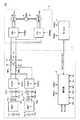
図1は、本発明の実施の形態に従う電源システム1を備える車両100の要部を示す概略構成図である。 FIG. 1 is a schematic configuration diagram showing a main part of a
図1を参照して、本実施の形態においては、負荷装置の一例として、車両100の駆動力を発生するための駆動力発生部3との間で電力授受を行なう構成について例示する。そして、車両100は、駆動力発生部3が電源システム1から供給される電力を受けて発生する駆動力を車輪(図示しない)に伝達することで走行する。 With reference to FIG. 1, in the present embodiment, as an example of a load device, a configuration in which power is transferred to and from drive
本実施の形態においては、複数の蓄電部の一例として、2つの蓄電部を有する電源システム1について説明する。電源システム1は、主正母線MPLおよび主負母線MNLを介して、駆動力発生部3との間で直流電力の授受を行なう。 In the present embodiment,
駆動力発生部3は、第1インバータINV1と、第2インバータINV2と、第1モータジェネレータMG1と、第2モータジェネレータMG2とを備え、HV_ECU(Hybrid Vehicle Electrical Control Unit)4からのスイッチング指令PWM1,PWM2に応じて駆動力を発生する。 The driving
インバータINV1,INV2は、主正母線MPLおよび主負母線MNLに並列接続され、それぞれ電源システム1との間で電力の授受を行なう。すなわち、インバータINV1,INV2は、それぞれ主正母線MPLおよび主負母線MNLを介して受ける直流電力を交流電力に変換してモータジェネレータMG1,MG2へ供給する。さらに、インバータINV1,INV2は、車両100の回生制動時などにおいて、モータジェネレータMG1,MG2が車両100の運動エネルギーを受けて発電する交流電力を直流電力に変換して回生電力として電源システム1へ返還するように構成されてもよい。一例として、インバータINV1,INV2は、三相分のスイッチング素子を含むブリッジ回路で構成され、それぞれHV_ECU4から受けたスイッチング指令PWM1,PWM2に応じて、スイッチング(回路開閉)動作を行なうことで、三相交流電力を発生する。 Inverters INV1 and INV2 are connected in parallel to main positive bus MPL and main negative bus MNL, and exchange power with
モータジェネレータMG1,MG2は、それぞれインバータINV1,INV2から供給される交流電力を受けて回転駆動力を発生可能であるとともに、外部からの回転駆動力を受けて交流電力を発電可能に構成される。一例として、モータジェネレータMG1,MG2は、永久磁石が埋設されたロータを備える三相交流回転電機である。そして、モータジェネレータMG1,MG2は、それぞれ動力伝達機構6と連結され、発生した駆動力を駆動軸8によって車輪(図示しない)へ伝達する。 Motor generators MG1 and MG2 are configured to receive AC power supplied from inverters INV1 and INV2, respectively, to generate rotational driving force, and to generate AC power by receiving external rotational driving force. As an example, motor generators MG1 and MG2 are three-phase AC rotating electric machines including a rotor in which permanent magnets are embedded. Motor generators MG1 and MG2 are connected to
なお、駆動力発生部3がハイブリッド車両に適用される場合には、モータジェネレータMG1,MG2は、動力伝達機構6または駆動軸8を介してエンジン(図示しない)とも機械的に連結される。そして、HV_ECU4によって、エンジンの発生する駆動力とモータジェネレータMG1,MG2の発生する駆動力とが最適な比率となるように制御が実行される。このようなハイブリッド車両に適用される場合には、一方のモータジェネレータをもっぱら電動機として機能させ、他方のモータジェネレータをもっぱら発電機として機能させるように構成することもできる。 When driving
HV_ECU4は、予め格納されたプログラムを実行することで、図示しない各センサから送信された信号、走行状況、アクセル開度の変化率、および格納しているマップなどに基づいて、モータジェネレータMG1,MG2のトルク目標値および回転数目標値を算出する。そして、HV_ECU4は、モータジェネレータMG1,MG2の発生トルクおよび回転数がそれぞれ当該算出したトルク目標値および回転数目標値となるように、スイッチング指令PWM1,PWM2を生成して駆動力発生部3へ与える。 The HV_ECU 4 executes a program stored in advance, so that the motor generators MG1, MG2 are based on a signal transmitted from each sensor (not shown), a traveling state, a change rate of the accelerator opening, a stored map, and the like. Torque target value and rotational speed target value are calculated. Then, HV_ECU 4 generates switching commands PWM1 and PWM2 and gives them to driving
また、HV_ECU4は、当該算出したトルク目標値および回転数目標値、もしくは図示しない各種センサにより検出したトルク実績値および回転数実績値に基づいて、モータジェネレータMG1,MG2のそれぞれにおいて生じる逆起電圧Vm1,Vm2を取得し、当該逆起電圧Vm1,Vm2に基づいて決定される電圧要求値Vm1*,Vm2*を電源システム1へ出力する。すなわち、HV_ECU4は、電源システム1からモータジェネレータMG1,MG2へ電力を供給できるように、逆起電圧Vm1,Vm2より大きい電圧を電圧要求値Vm1*,Vm2*として決定する。HV_ECU 4 also generates counter electromotive voltage Vm1 generated in each of motor generators MG1 and MG2 based on the calculated torque target value and rotation speed target value, or actual torque value and rotation speed actual value detected by various sensors (not shown). acquires Vm2, the counter electromotive voltage Vm1, the voltage required value is determined based on the Vm2Vm1 *, and outputs the Vm2* to
さらに、HV_ECU4は、上述のトルク目標値と回転数目標値との積、もしくはトルク実績値と回転数実績値との積に基づいて、電力要求P1*,P2*を算出して電源システム1へ出力する。なお、HV_ECU4は、電力要求P1*,P2*の符号を変化させることで、電力消費(正値)および電力回生(負値)といった駆動力発生部3における電力需給状態を電源システム1へ伝達する。Further, the HV_ECU 4 calculates the power demands P1* and P2* based on the product of the torque target value and the rotational speed target value, or the product of the actual torque value and the actual rotational speed value, to the
一方、電源システム1は、平滑コンデンサCと、供給電流検出部16と、供給電圧検出部18と、第1のコンバータCONV1と、第2のコンバータCONV2と、第1の蓄電部BAT1と、第2の蓄電部BAT2と、出力電流検出部10−1,10−2と、出力電圧検出部12−1,12−2と、蓄電部温度検出部14−1,14−2と、制御部2とを備える。 On the other hand, the
平滑コンデンサCは、主正母線MPLと主負母線MNLとの間に接続され、コンバータCONV1,CONV2からの供給電力に含まれる変動成分(交流成分)を低減する。 Smoothing capacitor C is connected between main positive bus MPL and main negative bus MNL, and reduces fluctuation components (AC components) included in the power supplied from converters CONV1 and CONV2.
供給電流検出部16は、主正母線MPLに直列に介挿され、駆動力発生部3への供給電流Ihを検出し、その検出結果を制御部2へ出力する。 Supply
供給電圧検出部18は、主正母線MPLと主負母線MNLとの間に接続され、駆動力発生部3への供給電圧Vhを検出し、その検出結果を制御部2へ出力する。 The
コンバータCONV1,CONV2は、主正母線MPLおよび主負母線MNLに並列接続され、それぞれ対応の蓄電部BAT1,BAT2と主正母線MPLおよび主負母線MNLとの間で電圧変換動作を行なう。具体的には、コンバータCONV1,CONV2は、それぞれ蓄電部BAT1,BAT2からの放電電力を目標電圧まで昇圧して供給電力を生成する。一例として、コンバータCONV1,CONV2は、チョッパ回路を含んで構成される。 Converters CONV1 and CONV2 are connected in parallel to main positive bus MPL and main negative bus MNL, and perform voltage conversion operations between corresponding power storage units BAT1 and BAT2, main positive bus MPL and main negative bus MNL, respectively. Specifically, converters CONV1 and CONV2 boost the discharge power from power storage units BAT1 and BAT2, respectively, to a target voltage to generate supply power. As an example, converters CONV1 and CONV2 are configured to include a chopper circuit.
蓄電部BAT1,BAT2は、それぞれコンバータCONV1,CONV2を介して、主正母線MPLおよび主負母線MNLに並列接続される。一例として、蓄電部BAT1,BAT2は、ニッケル水素電池やリチウムイオン電池などの充放電可能に構成された二次電池や、電気二重層キャパシタなどの蓄電素子から構成される。 Power storage units BAT1, BAT2 are connected in parallel to main positive bus MPL and main negative bus MNL through converters CONV1, CONV2, respectively. As an example, the power storage units BAT1 and BAT2 are configured by a secondary battery configured to be chargeable / dischargeable such as a nickel metal hydride battery or a lithium ion battery, or a power storage element such as an electric double layer capacitor.
出力電流検出部10−1,10−2は、それぞれ蓄電部BAT1,BAT2とコンバータCONV1,CONV2とを接続する2本の電力線の一方に介挿され、蓄電部BAT1,BAT2の入出力に係る出力電流Ib1,Ib2を検出し、その検出結果を制御部2へ出力する。 Output current detection units 10-1 and 10-2 are inserted into one of two power lines connecting power storage units BAT1 and BAT2 and converters CONV1 and CONV2, respectively, and outputs related to input / output of power storage units BAT1 and BAT2 The currents Ib1 and Ib2 are detected, and the detection results are output to the
出力電圧検出部12−1,12−2は、それぞれ蓄電部BAT1,BAT2とコンバータCONV1,CONV2とを接続する2本の電力線の線間に接続され、蓄電部BAT1,BAT2の出力電圧Vb1,Vb2を検出し、その検出結果を制御部2へ出力する。 Output voltage detection units 12-1 and 12-2 are connected between two power lines connecting power storage units BAT1 and BAT2 and converters CONV1 and CONV2, respectively, and output voltages Vb1 and Vb2 of power storage units BAT1 and BAT2 are connected. And the detection result is output to the
蓄電部温度検出部14−1,14−2は、それぞれ蓄電部BAT1,BAT2を構成する電池セルなどに近接して配置され、蓄電部BAT1,BAT2の内部温度である蓄電部温度Tb1,Tb2を検出し、その検出結果を制御部2へ出力する。なお、蓄電部温度検出部14−1,14−2は、それぞれ蓄電部BAT1,BAT2を構成する複数の電池セルに対応付けて配置された複数の検出素子の検出結果に基づいて、平均化処理などにより代表値を出力するように構成されてもよい。 The power storage unit temperature detection units 14-1 and 14-2 are arranged in proximity to the battery cells constituting the power storage units BAT1 and BAT2, respectively, and store the power storage unit temperatures Tb1 and Tb2 that are the internal temperatures of the power storage units BAT1 and BAT2. The detection result is output to the
制御部2は、HV_ECU4から受けた電圧要求値Vm1*,Vm2*および電力要求P1*,P2*と、供給電流検出部16から受けた供給電流Ihと、供給電圧検出部18から受けた供給電圧Vhと、出力電流検出部10−1,10−2から受けた出力電流Ib1,Ib2と、出力電圧検出部12−1,12−2から受けた出力電圧Vb1,Vb2と、蓄電部温度検出部14−1,14−2から受けた蓄電部温度Tb1,Tb2とに基づいて、後述する制御構造に従ってそれぞれスイッチング指令PWC1,PWC2を生成し、コンバータCONV1,CONV2における電圧変換動作を制御する。
特に、制御部2は、駆動力発生部3からの電力要求P1*,P2*に応じて、コンバータCONV1およびCONV2のうち、一方のコンバータの電圧変換動作を実行させるとともに、他方のコンバータの電圧変換動作を停止させる動作モード(以下、「片側停止モード」とも称す)を選択実行する。すなわち、駆動力発生部3からの電力要求P1*,P2*の合計値が蓄電部BAT1またはBAT2の充放電許容電力より小さければ、制御部2は、一方のコンバータの電圧変換動作を停止させて、電力変換損失を低減する。In particular, the
具体的には、制御部2は、片側停止モードにおける初期値として、蓄電部BAT1およびBAT2のうち、その出力電圧が大きい方の蓄電部に対応するコンバータを選択し、電圧変換動作を実行させる。これは、蓄電部間の不要な循環電流の発生を抑制し、蓄電部の異常劣化や不要な損失を回避するためである。すなわち、電圧変換動作を停止中のコンバータに接続される蓄電部の出力電圧が他の蓄電部の出力電圧より大きくなると、当該電圧変換動作を停止中のコンバータを逆流して、不要な循環電流が生じるからである。 Specifically,
さらに、制御部2は、電圧変換動作を実行中のコンバータに対応の蓄電部の出力電圧が、電圧変換動作を停止中のコンバータに対応の蓄電部の出力電圧よりも、所定のしきい値電圧を超えて低下したときに、電圧変換動作を実行させるコンバータを切換える。すなわち、制御部2は、片側停止モードにおけるコンバータの切換判定に関して、切換しきい値電圧で規定されるヒステリシス特性を有する。 Further, the
この切換しきい値電圧は、蓄電部における出力電圧の変動度合いに関連する状態値に応じて決定される。このような切換しきい値電圧を決定する状態値として、後述するように、蓄電部温度Tb1,Tb2、出力電流Ib1,Ib2、蓄電部BAT1,BAT2の内部抵抗、蓄電部BAT1,BAT2の劣化度合い、および蓄電部BAT1,BAT2の残存容量(SOC:State Of Charge)などが用いられる。 This switching threshold voltage is determined according to a state value related to the degree of fluctuation of the output voltage in the power storage unit. As state values for determining such a switching threshold voltage, as will be described later, power storage unit temperatures Tb1, Tb2, output currents Ib1, Ib2, internal resistances of power storage units BAT1, BAT2, and deterioration degrees of power storage units BAT1, BAT2 And the remaining capacity (SOC: State Of Charge) of power storage units BAT1, BAT2 are used.
さらに、上述の切換しきい値電圧として、コンバータCONV1からコンバータCONV2への切換判定に用いられる第1の切換しきい値電圧と、コンバータCONV2からコンバータCONV1への切換判断に用いられる第2の切換しきい値電圧とを互いに独立に設定してもよい。 Further, as the switching threshold voltage, the first switching threshold voltage used for switching determination from converter CONV1 to converter CONV2 and the second switching used for switching determination from converter CONV2 to converter CONV1. The threshold voltage may be set independently of each other.
なお、上述したように、蓄電部からの放電電流が電圧変換動作を停止しているコンバータを逆流するためには、他の蓄電部の出力電圧に対して、所定の電圧差が必要となるので、このようなヒステリシス特性を有するように構成したとしても、問題となるような循環電流が生じることはほとんどない。 As described above, in order for the discharge current from the power storage unit to reversely flow through the converter that has stopped the voltage conversion operation, a predetermined voltage difference is required with respect to the output voltage of the other power storage unit. Even if it is configured to have such a hysteresis characteristic, a circulating current causing a problem hardly occurs.
本発明の実施の形態においては、駆動力発生部3が「負荷装置」に相当し、主正母線MPLおよび主負母線MNLが「電力線」に相当し、コンバータCONV1,CONV2が「複数の電圧変換部」に相当する。また、制御部2が「動作モード選択手段」および「電圧変換部選択手段」を実現する。 In the embodiment of the present invention, the driving
図2は、本発明の実施の形態に従うコンバータCONV1,CONV2の概略構成図である。 FIG. 2 is a schematic configuration diagram of converters CONV1 and CONV2 according to the embodiment of the present invention.
図2を参照して、コンバータCONV1は、チョッパ回路40Aと、平滑コンデンサC1とからなる。 Referring to FIG. 2, converter CONV1 includes a
チョッパ回路40Aは、電力を双方向に供給することが可能である。具体的には、チョッパ回路40Aは、制御部2(図1)からのスイッチング指令PWC1に応じて、蓄電部BAT1からの放電電力を昇圧して駆動力発生部3(図1)へ供給可能であるとともに、駆動力発生部3から受けた回生電力を降圧して蓄電部BAT1へ供給可能である。そして、チョッパ回路40Aは、それぞれ正母線LN1Aと、負母線LN1Cと、配線LN1Bと、スイッチング素子であるトランジスタQ1A,Q1Bと、ダイオードD1A,D1Bと、インダクタL1とを含む。 The
正母線LN1Aは、その一方端がトランジスタQ1Aのコレクタに接続され、他方端が主正母線MPLに接続される。また、負母線LN1Cは、その一方端が蓄電部BAT1の負側に接続され、他方端が主負母線MNLに接続される。 Positive bus LN1A has one end connected to the collector of transistor Q1A and the other end connected to main positive bus MPL. Negative bus LN1C has one end connected to the negative side of power storage unit BAT1 and the other end connected to main negative bus MNL.
トランジスタQ1AおよびQ1Bは、正母線LN1Aと負母線LN1Cとの間に直列に接続される。そして、トランジスタQ1Aのコレクタは正母線LN1Aに接続され、トランジスタQ1Bのエミッタは負母線LN1Cに接続される。また、各トランジスタQ1A,Q1Bのコレクタ−エミッタ間には、エミッタ側からコレクタ側へ電流を流すダイオードD1A,D1Bがそれぞれ接続されている。さらに、インダクタL1は、トランジスタQ1AとトランジスタQ1Bとの接続点に接続される。 Transistors Q1A and Q1B are connected in series between positive bus LN1A and negative bus LN1C. Transistor Q1A has a collector connected to positive bus LN1A, and transistor Q1B has an emitter connected to negative bus LN1C. Further, diodes D1A and D1B that flow current from the emitter side to the collector side are connected between the collector and emitter of the transistors Q1A and Q1B, respectively. Further, inductor L1 is connected to a connection point between transistor Q1A and transistor Q1B.
配線LN1Bは、一方端が蓄電部BAT1の正側に接続され、他方端がインダクタL1に接続される。 Line LN1B has one end connected to the positive side of power storage unit BAT1, and the other end connected to inductor L1.
平滑コンデンサC1は、配線LN1Bと負母線LN1Cとの間に接続され、配線LN1Bと負母線LN1Cとの間の直流電圧に含まれる交流成分を低減する。 Smoothing capacitor C1 is connected between wiring LN1B and negative bus LN1C, and reduces the AC component included in the DC voltage between wiring LN1B and negative bus LN1C.
以下、コンバータCONV1の電圧変換動作について説明する。昇圧動作時において、制御部2(図1)は、トランジスタQ1Aをオン状態に維持し、かつ、トランジスタQ1Bを所定のデューティー比でオン/オフさせる。トランジスタQ1Bのオン期間においては、蓄電部BAT1から配線LN1B、インダクタL1、ダイオードD1A、および正母線LN1Aを順に介して、放電電流が主正母線MPLへ流れる。同時に、蓄電部BAT1から配線LN1B、インダクタL1、トランジスタQ1B、および負母線LN1Cを順に介して、ポンプ電流が流れる。インダクタL1は、このポンプ電流により電磁エネルギーを蓄積する。続いて、トランジスタQ1Bがオン状態からオフ状態に遷移すると、インダクタL1は、蓄積した電磁エネルギーを放電電流に重畳する。その結果、コンバータCONV1から主正母線MPLおよび主負母線MNLへ供給される直流電力の平均電圧は、デューティー比に応じてインダクタL1に蓄積される電磁エネルギーに相当する電圧だけ昇圧される。 Hereinafter, the voltage conversion operation of the converter CONV1 will be described. During the boosting operation, control unit 2 (FIG. 1) maintains transistor Q1A in the on state, and turns on / off transistor Q1B with a predetermined duty ratio. In the on period of transistor Q1B, a discharge current flows from power storage unit BAT1 to main positive bus MPL through wiring LN1B, inductor L1, diode D1A, and positive bus LN1A in this order. At the same time, a pump current flows from power storage unit BAT1 through wiring LN1B, inductor L1, transistor Q1B, and negative bus LN1C in this order. The inductor L1 accumulates electromagnetic energy by this pump current. Subsequently, when the transistor Q1B transitions from the on state to the off state, the inductor L1 superimposes the accumulated electromagnetic energy on the discharge current. As a result, the average voltage of the DC power supplied from converter CONV1 to main positive bus MPL and main negative bus MNL is boosted by a voltage corresponding to the electromagnetic energy stored in inductor L1 according to the duty ratio.
コンバータCONV2についても上述したコンバータCONV1と同様の構成および動作であるので、詳細な説明は繰返さない。 Since converter CONV2 has the same configuration and operation as converter CONV1 described above, detailed description thereof will not be repeated.
(片側停止モード)
図3は、片側停止モードにおいて駆動力発生部3との間で授受される電力を示す概略図である。(One-side stop mode)
FIG. 3 is a schematic diagram showing electric power exchanged with the driving
図3(a)は、コンバータCONV1が選択されて電力変換動作を行なう場合を示す。
図3(b)は、コンバータCONV2が選択されて電力変換動作を行なう場合を示す。FIG. 3A shows a case where converter CONV1 is selected to perform a power conversion operation.
FIG. 3B shows a case where the converter CONV2 is selected and a power conversion operation is performed.
図3(a)を参照して、片側停止モードに移行した直後において、蓄電部BAT1の出力電圧Vb1が蓄電部BAT2の出力電圧Vb2より大きい場合には、コンバータCONV1が電圧変換動作を実行するとともに、コンバータCONV2が電圧変換動作を停止する。すると、駆動力発生部3には、コンバータCONV1を介して、蓄電部BAT1からの放電電力Paが供給される。 Referring to FIG. 3A, immediately after the transition to the one-side stop mode, when output voltage Vb1 of power storage unit BAT1 is higher than output voltage Vb2 of power storage unit BAT2, converter CONV1 performs a voltage conversion operation. The converter CONV2 stops the voltage conversion operation. Then, the driving
一方、図3(b)を参照して、片側停止モードに移行した直後において、蓄電部BAT2の出力電圧Vb2が蓄電部BAT1の出力電圧Vb1より大きい場合には、コンバータCONV2が電圧変換動作を実行するとともに、コンバータCONV1が電圧変換動作を停止する。すると、駆動力発生部3には、コンバータCONV2を介して、蓄電部BAT2からの放電電力Pbが供給される。 On the other hand, referring to FIG. 3B, immediately after shifting to the one-side stop mode, when output voltage Vb2 of power storage unit BAT2 is higher than output voltage Vb1 of power storage unit BAT1, converter CONV2 performs a voltage conversion operation. At the same time, the converter CONV1 stops the voltage conversion operation. Then, the driving
上述のように、片側停止モードにおいては、2つのコンバータCONV1,CONV2のうち、一方の電圧変換動作が停止されるので、チョッパ回路40A,40B(図2)などにおけるスイッチング損失(電力変換損失)を低減できる。 As described above, in the one-side stop mode, one of the two converters CONV1 and CONV2 is stopped. Therefore, the switching loss (power conversion loss) in the
(制御構造)
図4は、本発明の実施の形態に従う制御部2における制御構造を示すブロック図である。(Control structure)
FIG. 4 is a block diagram showing a control structure in
図4を参照して、本発明の実施の形態に従う制御構造は、コンバータCONV1,CONV2における電圧変換動作(昇圧動作)を制御するためのスイッチング指令PWC1A,PWC2Aを生成する。そして、本発明の実施の形態に従う制御構造は、目標値・モード決定部50と、減算部54a,54b,58a,58bと、比例積分部(PI)56a,56bと、選択部60a,60bと、変調部(MOD)62a,62bとを含む。 Referring to FIG. 4, the control structure according to the embodiment of the present invention generates switching commands PWC1A and PWC2A for controlling the voltage conversion operation (boost operation) in converters CONV1 and CONV2. The control structure according to the embodiment of the present invention includes a target value /
減算部54aおよび比例積分部56aは、コンバータCONV1についての電圧フィードバック制御要素を構成し、主正母線MPLと主負母線MNLとの間の供給電圧Vhを目標電圧Vh*に一致させるように制御出力を生成する。また、減算部58aは、コンバータCONV1についての電圧フィードフォワード制御要素を構成し、比例積分部56aから出力される制御出力を補償して、デューティー指令#Ton1A(暫定値)を生成する。
選択部60aは、デューティー指令#Ton1A(暫定値)および「0」値を入力され、選択指令SEL1に応じて、いずれか一方をデューティー指令Ton1Aとして変調部62aへ出力する。 The
変調部62aは、図示しない発振部が発生する搬送波(キャリア波)とデューティー指令Ton1Aとを比較して、スイッチング指令PWC1Aを生成して、コンバータCONV1へ与える。したがって、デューティー指令Ton1Aとして、選択部60aからデューティー指令#Ton1A(暫定値)が出力されると、コンバータCONV1は電圧変換動作を実行する一方、選択部60aから「0」値が出力されると、コンバータCONV1は電圧変換動作を停止する。
同様に、減算部54bおよび比例積分部56bは、コンバータCONV2についての電圧フィードバック制御要素を構成し、主正母線MPLと主負母線MNLとの間の供給電圧Vhを目標電圧Vh*に一致させるように制御出力を生成する。また、減算部58bは、コンバータCONV2についての電圧フィードフォワード制御要素を構成し、比例積分部56bから出力される制御出力を補償して、デューティー指令#Ton2A(暫定値)を生成する。Similarly,
選択部60bは、デューティー指令#Ton2A(暫定値)および「0」値を入力され、選択指令SEL2に応じて、いずれか一方をデューティー指令Ton2Aとして変調部62bへ出力する。 The
変調部62bは、図示しない発振部が発生する搬送波(キャリア波)とデューティー指令Ton2Aとを比較して、スイッチング指令PWC2Aを生成して、コンバータCONV2へ与える。したがって、デューティー指令Ton2Aとして、選択部60bからデューティー指令#Ton2A(暫定値)が出力されると、コンバータCONV2は電圧変換動作を実行する一方、選択部60bから「0」値が出力されると、コンバータCONV2は電圧変換動作を停止する。
なお、比例積分部56a,56bは、それぞれ少なくとも比例要素(P:proportional element)および積分要素(I:integral element)を含んで構成され、目標電圧Vh*と供給電圧Vhとの偏差に応じた制御出力を所定のゲインおよび時定数に従って出力する。Each of the
目標値・モード決定部50は、HV_ECU4から受けた電圧要求値Vm1*,Vm2*に応じて目標電圧Vh*を決定し、減算部54a,54bへ出力する。また、目標値・モード決定部50は、片側停止モード判定部51と、ヒステリシス特性部52とを含む。Target
片側停止モード判定部51は、駆動力発生部3からの電力要求P1*,P2*に応じて、片側停止モードを選択すべきか否かを判定する。そして、片側停止モード判定部51は、片側停止モードを選択すべきと判定すると、その信号をヒステリシス特性部52へ出力する。The one-side stop mode determination unit 51 determines whether or not the one-side stop mode should be selected according to the power requests P1* and P2* from the driving
ヒステリシス特性部52は、片側停止モード判定部51から片側停止モードの選択を示す信号を受けると、初期値として、出力電圧が大きい方の蓄電部に対応するコンバータを選択する。そして、ヒステリシス特性部52は、選択したコンバータに対応するSEL1,SEL2のいずれか一方だけを出力する。 When the hysteresis
さらに、ヒステリシス特性部52は、所定の切換しきい値電圧で規定されるヒステリシス特性に従って、選択指令SEL1,SEL2を切換える。すなわち、ヒステリシス特性部52は、出力電圧Vb1と出力電圧Vb2との間の電圧差が切換しきい値電圧以上になった時点で選択指令SEL1,SEL2の切換を実行する。さらに、ヒステリシス特性部52は、出力電圧Vb1,Vb2の変動度合いに関連する蓄電部BAT1,BAT2の状態値に応じて、切換しきい値電圧を決定する。 Furthermore, hysteresis
(ヒステリシス特性)
図5は、ヒステリシス特性部52のより詳細な動作を説明するための図である。(Hysteresis characteristics)
FIG. 5 is a diagram for explaining a more detailed operation of the hysteresis
図5を参照して、ヒステリシス特性部52は、出力電圧Vb1と出力電圧Vb2との電圧差に応じて、選択指令SEL1,SEL2の出力を切換える。具体的には、ヒステリシス特性部52は、現在の選択状態(履歴)に依存する状態特性ST1およびST2に従って、選択指令SEL1,SEL2の出力を切換える。すなわち、ヒステリシス特性部52は、選択指令SEL1が選択中であれば、状態特性ST1に従って切換判定を実行する一方、選択指令SEL2が選択中であれば、状態特性ST2に従って切換判定を実行する。 Referring to FIG. 5, hysteresis
したがって、ヒステリシス特性部52は、蓄電部BAT1の出力電圧Vb1が蓄電部BAT2の出力電圧Vb2に比較して僅かに小さくなった場合でも選択指令SEL1の選択を維持する。そして、出力電圧Vb1が出力電圧Vb2に比較して、第1の切換しきい値電圧Vth1を超えて低下すれば、ヒステリシス特性部52は、選択指令SEL1を選択指令SEL2に切換えて出力する(遷移特性TR12)。 Therefore, hysteresis
また同様に、ヒステリシス特性部52は、蓄電部BAT2の出力電圧Vb2が蓄電部BAT1の出力電圧Vb1に比較して僅かに小さくなった場合でも選択指令SEL2の選択を維持する。そして、出力電圧Vb2が出力電圧Vb1に比較して、第2の切換しきい値電圧Vth2を超えて低下すれば、ヒステリシス特性部52は、選択指令SEL2を選択指令SEL1に切換えて出力する(遷移特性TR21)。 Similarly, hysteresis
上述したヒステリシス特性部52によれば、出力電圧Vb1と出力電圧Vb2との間の電圧差が、(−)側の切換しきい値電圧Vth1および(+)側の切換しきい値電圧Vth2の範囲内で変動する限りは、選択指令SEL1,SEL2の切換は実行されず、現在選択中の選択指令(すなわち、電圧変換動作を実行するコンバータの選択)が維持される。 According to the hysteresis
図6は、本発明の実施の形態に従うヒステリシス特性部52を用いて実行される片側停止モードの一例を説明するための図である。 FIG. 6 is a diagram illustrating an example of the one-side stop mode executed using hysteresis
図6(a)は、出力電圧Vb1と出力電圧Vb2との間の電圧差の時間的変化を示す。
図6(b)は、従来技術に従う選択指令の時間的変化を示す。FIG. 6A shows a temporal change in the voltage difference between the output voltage Vb1 and the output voltage Vb2.
FIG. 6B shows a temporal change of the selection command according to the prior art.
図6(c)は、本発明の実施の形態に従うヒステリシス特性部52から出力される選択指令の時間的変化を示す。 FIG. 6C shows a temporal change in the selection command output from hysteresis
図6(a)に示すような出力電圧Vb1と出力電圧Vb2との間の電圧差(Vb1−Vb2)の時間的変化を例にとると、出力電圧Vb1と出力電圧Vb2との間の電圧差がゼロクロスする時刻は、それぞれ時刻tm1〜tm8となる。 Taking the time change of the voltage difference (Vb1-Vb2) between the output voltage Vb1 and the output voltage Vb2 as shown in FIG. 6A as an example, the voltage difference between the output voltage Vb1 and the output voltage Vb2 Are zero-crossed times tm1 to tm8, respectively.
図6(b)を参照して、従来技術によれば、図6(a)に示す時刻tm1〜tm8の各々において、出力される選択指令は切換えられる。その結果、時刻tm1〜tm8の期間において、合計8回の選択指令の切換が行なわれることになる。特に、時刻tm3〜tm8の期間においては、頻繁に選択指令の切換が生じていることがわかる。 Referring to FIG. 6 (b), according to the prior art, the selection command to be output is switched at each of times tm1 to tm8 shown in FIG. 6 (a). As a result, the selection command is switched eight times in total during the period from time tm1 to tm8. In particular, during the period from time tm3 to tm8, it can be seen that selection command switching frequently occurs.
図6(c)を参照して、本発明の実施の形態1に従うヒステリシス特性部52は、切換しきい値電圧Vth1およびVt2で規定されるヒステリシス特性に従って、選択指令の切換を実行する。そのため、出力電圧Vb1と出力電圧Vb2との間の電圧差がゼロクロスする時刻tm1では、選択指令SEL1からSEL2への切換は実行されない。その後、出力電圧Vb1と出力電圧Vb2との間の電圧差が切換しきい値電圧Vth1となった時刻tm1#において、はじめて選択指令SEL1から選択指令SEL2への切換が実行される。 Referring to FIG. 6 (c), hysteresis
同様にして、選択指令SEL2から選択指令SEL1への切換は、出力電圧Vb1と出力電圧Vb2との間の電圧差が切換しきい値電圧Vth2となった時刻tm2#において実行される。 Similarly, switching from selection command SEL2 to selection command SEL1 is executed at time tm2 # when the voltage difference between output voltage Vb1 and output voltage Vb2 becomes switching threshold voltage Vth2.
さらに、時刻tm3〜tm8の期間における出力電圧Vb1と出力電圧Vb2との間の電圧差は、切換しきい値電圧Vth1およびVth2の範囲内で変動するだけであるので、選択指令の切換は実行されず、選択指令SEL1が継続的に出力される。 Furthermore, since the voltage difference between the output voltage Vb1 and the output voltage Vb2 during the period from time tm3 to tm8 only varies within the range of the switching threshold voltages Vth1 and Vth2, the selection command is switched. Instead, the selection command SEL1 is continuously output.
このように、この発明の実施の形態1に従うヒステリシス特性部52によれば、選択指令の頻繁な切換を抑制できる。よって、片側停止モードにおいて、駆動力発生部3への供給電圧、およびコンバータCONV1,CONV2における電圧変換動作を安定化できる。 Thus, according to hysteresis
(切換しきい値電圧の決定)
上述の図6(a)に示すような出力電圧Vb1と出力電圧Vb2との間の電圧差の時間的変化は、蓄電部BAT1,BAT2における出力電圧Vb1,Vb2の変動度合いに大きく影響される。すなわち、出力電圧Vb1,Vb2の変動度合いが大きければ、出力電圧Vb1と出力電圧Vb2との間の電圧差も大きく変動することになる。そのため、出力電圧Vb1,Vb2の変動度合いが大きければ、切換しきい値電圧Vth1,Vth2も大きくして、電力変換動作を実行するコンバータの切換頻度を抑制することが望ましい。(Determination of switching threshold voltage)
The temporal change in the voltage difference between the output voltage Vb1 and the output voltage Vb2 as shown in FIG. 6A is greatly influenced by the degree of fluctuation of the output voltages Vb1 and Vb2 in the power storage units BAT1 and BAT2. That is, if the variation degree of the output voltages Vb1 and Vb2 is large, the voltage difference between the output voltage Vb1 and the output voltage Vb2 also varies greatly. Therefore, if the degree of fluctuation of output voltages Vb1 and Vb2 is large, it is desirable to increase switching threshold voltages Vth1 and Vth2 to suppress the switching frequency of the converter that performs the power conversion operation.
そこで、本発明の実施の形態に従うヒステリシス特性部52は、蓄電部BAT1,BAT2の出力電圧Vb1,Vb2の変動度合いに関連する状態値に応じて、切換しきい値電圧Vth1,Vth2を決定する。ヒステリシス特性部52は、このような切換しきい値電圧Vth1,Vth2を決定する状態値として、蓄電部温度Tb1,Tb2、出力電流Ib1,Ib2、蓄電部BAT1,BAT2の内部抵抗、蓄電部BAT1,BAT2の劣化度合い、および蓄電部BAT1,BAT2の残存容量SOCなどを用いる。以下、各状態値について詳述する。 Therefore, hysteresis
なお、以下の説明においては、蓄電部BAT1,BAT2、蓄電部温度Tb1,Tb2、出力電流Ib1,Ib2、出力電圧Vb1,Vb2および切換しきい値電圧Vth1,Vth2をそれぞれ総称する場合には、単に「蓄電部BAT」、「蓄電部温度Tb」、「出力電流Ib」、「出力電圧Vb」および「切換しきい値電圧Vth」とも称す。 In the following description, power storage units BAT1, BAT2, power storage unit temperatures Tb1, Tb2, output currents Ib1, Ib2, output voltages Vb1, Vb2, and switching threshold voltages Vth1, Vth2 are simply referred to Also referred to as “power storage unit BAT”, “power storage unit temperature Tb”, “output current Ib”, “output voltage Vb”, and “switching threshold voltage Vth”.
(蓄電部温度および出力電流との関連性)
図7は、蓄電部BATの出力電圧Vbの変動度合いと、蓄電部温度Tbおよび出力電流Ibとの関連を説明するための図である。(Relationship with power storage unit temperature and output current)
FIG. 7 is a diagram for explaining the relationship between the degree of fluctuation of output voltage Vb of power storage unit BAT, power storage unit temperature Tb, and output current Ib.
図7を参照して、蓄電部温度TbがそれぞれT1およびT2(T1<T2)である場合について、出力電流Ibに対する出力電圧Vbの変化を示す2つのIb−Vb特性が示される。 Referring to FIG. 7, two Ib-Vb characteristics indicating changes in output voltage Vb with respect to output current Ib are shown for power storage unit temperatures Tb of T1 and T2 (T1 <T2), respectively.
これらのIb−Vb特性において、出力電流IbがいずれもI1となる2つのポイントPt1(Tb=T2)およびPt2(Tb=T1)についての電圧変動を比較する。ポイントPt1において、出力電流Ibの電流変動ΔIに対する出力電圧Vbの変動分は、電圧変動ΔV1に相当する。一方、ポイントPt2において、出力電流Ibの電流変動ΔIに対する出力電圧Vbの変動分は、電圧変動ΔV2に相当する。 In these Ib-Vb characteristics, voltage fluctuations at two points Pt1 (Tb = T2) and Pt2 (Tb = T1) at which the output current Ib is I1 are compared. At the point Pt1, the variation of the output voltage Vb with respect to the current variation ΔI of the output current Ib corresponds to the voltage variation ΔV1. On the other hand, at the point Pt2, the fluctuation of the output voltage Vb with respect to the current fluctuation ΔI of the output current Ib corresponds to the voltage fluctuation ΔV2.
ここで、電圧変動ΔV2>電圧変動ΔV1であるので、(電圧変動ΔV2/電流変動ΔI)>(電圧変動ΔV1/電流変動ΔI)が成立する。すなわち、駆動力発生部3(図1)との間の授受電力の変動に伴って、蓄電部BATの出力電流Ibが変動する場合には、蓄電部温度Tbが低いほど、蓄電部BATの出力電圧Vbの変動度合いが大きくなることを意味する。 Here, since voltage fluctuation ΔV2> voltage fluctuation ΔV1, (voltage fluctuation ΔV2 / current fluctuation ΔI)> (voltage fluctuation ΔV1 / current fluctuation ΔI) is established. That is, when the output current Ib of the power storage unit BAT varies with the fluctuation of the power exchanged with the driving force generation unit 3 (FIG. 1), the output of the power storage unit BAT decreases as the power storage unit temperature Tb decreases. This means that the degree of fluctuation of the voltage Vb increases.
したがって、片側停止モードをより安定化させる観点からは、蓄電部BATの蓄電部温度Tbが低いほど、切換しきい値電圧Vthを大きくすることが望ましい。 Therefore, from the viewpoint of further stabilizing the one-side stop mode, it is desirable to increase switching threshold voltage Vth as power storage unit temperature Tb of power storage unit BAT is lower.
また、蓄電部温度Tb=T2の場合のIb−Vb特性において、出力電流IbがそれぞれI1およびI2となる2つのポイントPt1およびP3についての電圧変動を比較する。ポイントPt1において、出力電流Ibの電流変動ΔIに対する出力電圧Vbの変動分は、電圧変動ΔV1に相当する。一方、ポイントPt3において、同一の電流変動ΔIに対する出力電圧Vbの変動分は、電圧変動ΔV3に相当する。 Further, in the Ib-Vb characteristics when the power storage unit temperature Tb = T2, the voltage fluctuations at two points Pt1 and P3 at which the output current Ib becomes I1 and I2 are compared. At the point Pt1, the variation of the output voltage Vb with respect to the current variation ΔI of the output current Ib corresponds to the voltage variation ΔV1. On the other hand, at the point Pt3, the fluctuation of the output voltage Vb with respect to the same current fluctuation ΔI corresponds to the voltage fluctuation ΔV3.
ここで、電圧変動ΔV3>電圧変動ΔV1であるので、(電圧変動ΔV3/電流変動ΔI)>(電圧変動ΔV1/電流変動ΔI)が成立する。すなわち、駆動力発生部3(図1)との間の授受電力の変動に伴って、蓄電部BATの出力電流Ibが変動する場合には、出力電流Ibの絶対値が大きいほど、蓄電部BATの出力電圧Vbの変動度合いが大きいことを意味する。 Here, since voltage fluctuation ΔV3> voltage fluctuation ΔV1, (voltage fluctuation ΔV3 / current fluctuation ΔI)> (voltage fluctuation ΔV1 / current fluctuation ΔI) is established. That is, when the output current Ib of the power storage unit BAT fluctuates with the fluctuation of power exchanged with the driving force generation unit 3 (FIG. 1), the larger the absolute value of the output current Ib, the larger the power storage unit BAT. This means that the degree of fluctuation of the output voltage Vb is large.
したがって、片側停止モードをより安定化させる観点からは、蓄電部BATの出力電流Ibの絶対値が大きいほど、切換しきい値電圧Vthを大きくすることが望ましい。 Therefore, from the viewpoint of further stabilizing the one-side stop mode, it is desirable to increase switching threshold voltage Vth as the absolute value of output current Ib of power storage unit BAT increases.
上述したような特性に基づいて、ヒステリシス特性部52(図4)は、一例として、切換しきい値電圧Vth1を蓄電部温度Tbおよび出力電流Ibと対応付けて規定したマップを予め格納する。そして、ヒステリシス特性部52は、蓄電部BAT1,BAT2の少なくとも一方の蓄電部温度Tbや出力電流Ibに応じて、切換しきい値電圧Vthを変更する。 Based on the characteristics as described above, for example, hysteresis characteristic unit 52 (FIG. 4) stores in advance a map that defines switching threshold voltage Vth1 in association with power storage unit temperature Tb and output current Ib. Hysteresis
図8は、切換しきい値電圧Vthを蓄電部温度Tbおよび出力電流Ibと対応付けて規定したマップの一例を示す図である。 FIG. 8 is a diagram showing an example of a map in which switching threshold voltage Vth is defined in association with power storage unit temperature Tb and output current Ib.
図8を参照して、蓄電部温度Tbが低いほど、また出力電流Ibが大きいほど、切換しきい値電圧Vthはより大きい値に決定される。 Referring to FIG. 8, switching threshold voltage Vth is determined to be larger as power storage unit temperature Tb is lower and output current Ib is larger.
(蓄電部の内部抵抗および蓄電部の劣化度合いとの関連性)
図9は、蓄電部BATの出力電圧Vbの変動度合いと、蓄電部BATの内部抵抗および蓄電部BATの劣化度合いとの関連を説明するための図である。(Relationship between internal resistance of power storage unit and degree of deterioration of power storage unit)
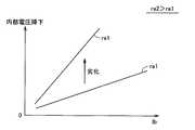
FIG. 9 is a diagram for explaining the relationship between the degree of fluctuation of output voltage Vb of power storage unit BAT and the internal resistance of power storage unit BAT and the degree of deterioration of power storage unit BAT.
図9を参照して、蓄電部BATは、分極作用などに起因する内部抵抗を有する。この内部抵抗を流れる出力電流Ibにより生じる内部電圧降下によって、蓄電部BATの出力電圧Vbは低下する。このような内部電圧降下は、内部抵抗と出力電流Ibとの積に比例するため、内部抵抗もしくは出力電流Ibが大きいほど、蓄電部BATの出力電圧Vbの変動度合いは大きくなる。 Referring to FIG. 9, power storage unit BAT has an internal resistance due to a polarization action or the like. Due to the internal voltage drop caused by the output current Ib flowing through the internal resistance, the output voltage Vb of the power storage unit BAT decreases. Since such an internal voltage drop is proportional to the product of the internal resistance and the output current Ib, the degree of fluctuation of the output voltage Vb of the power storage unit BAT increases as the internal resistance or the output current Ib increases.
さらに、内部抵抗は、蓄電部BATの劣化度合いによって増大する傾向を示す。一例として、劣化前に内部抵抗ra1を有していた蓄電部BATが劣化して、その内部抵抗がra2まで増大したとすると、内部電圧降下の大きさも増大する。したがって、蓄電部BATの劣化度合いは、蓄電部BATの内部抵抗の大きさ、すなわち蓄電部BATの出力電圧Vbの変動度合いに関連する。 Furthermore, the internal resistance tends to increase depending on the degree of deterioration of power storage unit BAT. As an example, if the power storage unit BAT having the internal resistance ra1 before deterioration deteriorates and the internal resistance increases to ra2, the magnitude of the internal voltage drop also increases. Therefore, the degree of deterioration of power storage unit BAT is related to the magnitude of the internal resistance of power storage unit BAT, that is, the degree of fluctuation of output voltage Vb of power storage unit BAT.
したがって、片側停止モードをより安定化させる観点からは、蓄電部BATの内部抵抗、もしくは蓄電部BATの劣化度合いが大きいほど、切換しきい値電圧Vthを大きくすることが望ましい。 Therefore, from the viewpoint of further stabilizing the one-side stop mode, it is desirable to increase switching threshold voltage Vth as the internal resistance of power storage unit BAT or the deterioration degree of power storage unit BAT increases.
上述したような特性に基づいて、ヒステリシス特性部52(図4)は、一例として、切換しきい値電圧Vthを蓄電部BATの内部抵抗、もしくは蓄電部BATの劣化度合いと対応付けて規定したマップを予め格納する。そして、ヒステリシス特性部52は、蓄電部BAT1,BAT2の少なくとも一方の内部抵抗、もしくは劣化度合いに応じて、切換しきい値電圧Vthを変更する。 Based on the characteristics as described above, for example, the hysteresis characteristic unit 52 (FIG. 4) defines the switching threshold voltage Vth in association with the internal resistance of the power storage unit BAT or the deterioration degree of the power storage unit BAT. Is stored in advance. Hysteresis
図10は、切換しきい値電圧Vthを蓄電部BATの内部抵抗、もしくは蓄電部BATの劣化度合いと対応付けて規定したマップの一例を示す図である。 FIG. 10 is a diagram showing an example of a map in which switching threshold voltage Vth is defined in association with the internal resistance of power storage unit BAT or the degree of deterioration of power storage unit BAT.
図10を参照して、蓄電部BATの内部抵抗、もしくは蓄電部BATの劣化度合いが大きいほど、切換しきい値電圧Vthはより大きい値に決定される。また、蓄電部温度Tbが低いほど、切換しきい値電圧Vthはより大きい値に決定される。 Referring to FIG. 10, switching threshold voltage Vth is determined to be larger as the internal resistance of power storage unit BAT or the deterioration degree of power storage unit BAT is larger. In addition, switching threshold voltage Vth is determined to be larger as power storage unit temperature Tb is lower.
なお、蓄電部BATの内部抵抗を測定する方法としては、周知のさまざまな手段を用いることができるが、一例として、蓄電部BATの出力電圧Vbと出力電流Ibとをプロットし、出力電流Ibに対する出力電圧Vbの変化量として得られる傾きから内部抵抗を測定できる。 As a method for measuring the internal resistance of power storage unit BAT, various known means can be used. As an example, the output voltage Vb and output current Ib of power storage unit BAT are plotted, and the output current Ib is plotted. The internal resistance can be measured from the slope obtained as the change amount of the output voltage Vb.
また、蓄電部BATの劣化度合いを測定する方法としては、周知のさまざまな手段を用いることができるが、一例として、蓄電部BATの出力電圧Vbが所定の電圧変化を生じるのに要する電荷量(電力)に基づいて推定される満充電容量から劣化度合い(満充電容量の減少率)を測定できる。 In addition, various known means can be used as a method of measuring the degree of deterioration of the power storage unit BAT. As an example, the amount of charge required for the output voltage Vb of the power storage unit BAT to generate a predetermined voltage change ( It is possible to measure the degree of deterioration (decrease rate of full charge capacity) from the full charge capacity estimated based on (electric power).
(蓄電部の残存容量および蓄電部の劣化度合いとの関連性)
図11は、蓄電部BATの出力電圧Vbの変動度合いと、蓄電部BATの残存容量SOCおよび蓄電部BATの劣化度合いとの関連を説明するための図である。(Relationship between remaining capacity of power storage unit and degree of deterioration of power storage unit)
FIG. 11 is a diagram for explaining the relationship between the degree of fluctuation of output voltage Vb of power storage unit BAT and the remaining capacity SOC of power storage unit BAT and the degree of deterioration of power storage unit BAT.
図11を参照して、蓄電部BATの劣化前および劣化後の場合について、残存容量SOCに対する出力電圧Vbの関係を規定する2つのSOC−Vb特性が示される。 Referring to FIG. 11, two SOC-Vb characteristics defining the relationship of output voltage Vb with respect to remaining capacity SOC are shown for power storage unit BAT before and after deterioration.
SOC−Vb特性(劣化前)において、残存容量SOCがそれぞれSOC1およびSOC2となる2つのポイントPt4およびP5についての電圧変動を比較する。ポイントPt4において、残存容量SOCの残存容量変動ΔSOCに対する出力電圧Vbの変動分は、電圧変動ΔV4に相当する。一方、ポイントPt5において、同一の残存容量変動ΔSOCに対する出力電圧Vbの変動分は、電圧変動ΔV5に相当する。 In the SOC-Vb characteristics (before deterioration), voltage fluctuations at two points Pt4 and P5 at which the remaining capacity SOC becomes SOC1 and SOC2 are compared. At the point Pt4, the fluctuation of the output voltage Vb with respect to the remaining capacity fluctuation ΔSOC of the remaining capacity SOC corresponds to the voltage fluctuation ΔV4. On the other hand, at the point Pt5, the fluctuation of the output voltage Vb with respect to the same remaining capacity fluctuation ΔSOC corresponds to the voltage fluctuation ΔV5.
ここで、電圧変動ΔV4<電圧変動ΔV5であるので、(電圧変動ΔV4/残存容量変動ΔSOC)<(電圧変動ΔV5/残存容量変動ΔSOC)が成立する。すなわち、駆動力発生部3(図1)への電力供給に伴って、蓄電部BATの残存容量SOCが時間的に低下する場合には、残存容量SOCの絶対値が小さいほど、出力電圧Vbの変動度合いが大きいことを意味する。 Here, since voltage fluctuation ΔV4 <voltage fluctuation ΔV5, (voltage fluctuation ΔV4 / remaining capacity fluctuation ΔSOC) <(voltage fluctuation ΔV5 / remaining capacity fluctuation ΔSOC) is established. That is, when the remaining capacity SOC of the power storage unit BAT decreases with time as power is supplied to the driving force generation unit 3 (FIG. 1), the smaller the absolute value of the remaining capacity SOC is, the lower the output voltage Vb is. It means that the degree of fluctuation is large.
また、蓄電部BATの残存容量SOCの絶対値が満充電容量に近い場合にも、蓄電部BATの出力電圧Vbの変動度合いが大きくなる。 Even when the absolute value of the remaining capacity SOC of the power storage unit BAT is close to the full charge capacity, the degree of fluctuation of the output voltage Vb of the power storage unit BAT increases.
したがって、片側停止モードをより安定化させる観点からは、残存容量SOCの絶対値に応じて、切換しきい値電圧Vthを変化させることが望ましい。 Therefore, from the viewpoint of further stabilizing the one-side stop mode, it is desirable to change the switching threshold voltage Vth according to the absolute value of the remaining capacity SOC.
また、SOC−Vb特性(劣化前)およびSOC−Vb特性(劣化後)において、残存容量SOCがいずれもSOC1となる2つのポイントPt4およびP6についての電圧変動を比較する。ポイントPt4において、残存容量SOCの残存容量変動ΔSOCに対する出力電圧Vbの変動分は、電圧変動ΔV4に相当する。一方、ポイントPt6において、残存容量SOCの残存容量変動ΔSOCに対する出力電圧Vbの変動分は、電圧変動ΔV6に相当する。 Further, in the SOC-Vb characteristic (before deterioration) and the SOC-Vb characteristic (after deterioration), voltage fluctuations at two points Pt4 and P6 at which the remaining capacity SOC becomes SOC1 are compared. At the point Pt4, the fluctuation of the output voltage Vb with respect to the remaining capacity fluctuation ΔSOC of the remaining capacity SOC corresponds to the voltage fluctuation ΔV4. On the other hand, at the point Pt6, the fluctuation of the output voltage Vb with respect to the remaining capacity fluctuation ΔSOC of the remaining capacity SOC corresponds to the voltage fluctuation ΔV6.
ここで、電圧変動ΔV6>電圧変動ΔV4であるので、(電圧変動ΔV6/残存容量変動ΔSOC)>(電圧変動ΔV4/残存容量変動ΔSOC)が成立する。すなわち、駆動力発生部3(図1)との間の授受電力の変動に伴って、蓄電部BATの出力電流Ibが変動する場合には、蓄電部BATの劣化度合いが大きいほど、蓄電部BATの出力電圧Vbの変動度合いが大きいことを意味する。 Here, since voltage fluctuation ΔV6> voltage fluctuation ΔV4, (voltage fluctuation ΔV6 / remaining capacity fluctuation ΔSOC)> (voltage fluctuation ΔV4 / remaining capacity fluctuation ΔSOC) is established. That is, when the output current Ib of the power storage unit BAT varies with the variation in the power exchanged with the driving force generation unit 3 (FIG. 1), the greater the degree of deterioration of the power storage unit BAT, the greater the power storage unit BAT. This means that the degree of fluctuation of the output voltage Vb is large.
したがって、片側停止モードをより安定化させる観点からは、蓄電部BATの劣化度合いが大きいほど、切換しきい値電圧Vthを大きくすることが望ましい。 Therefore, from the viewpoint of further stabilizing the one-side stop mode, it is desirable to increase switching threshold voltage Vth as the degree of deterioration of power storage unit BAT increases.
上述したような特性に基づいて、ヒステリシス特性部52(図4)は、一例として、切換しきい値電圧Vthを蓄電部BATの残存容量SOCおよび蓄電部BATの劣化度合いと対応付けて規定したマップを予め格納する。そして、ヒステリシス特性部52は、蓄電部BAT1,BAT2の少なくとも一方の残存容量SOCおよび劣化度合いに応じて、切換しきい値電圧Vthを変更する。 Based on the characteristics as described above, for example, hysteresis characteristic unit 52 (FIG. 4) defines a map in which switching threshold voltage Vth is defined in association with remaining capacity SOC of power storage unit BAT and the degree of deterioration of power storage unit BAT. Is stored in advance. Hysteresis
図12は、切換しきい値電圧Vthを蓄電部BATの残存容量SOCおよび蓄電部BATの劣化度合いと対応付けて規定したマップの一例を示す図である。 FIG. 12 is a diagram showing an example of a map in which switching threshold voltage Vth is defined in association with remaining capacity SOC of power storage unit BAT and the degree of deterioration of power storage unit BAT.
図12を参照して、蓄電部BATの残存容量SOCが中間値であるほど、切換しきい値電圧Vthはより小さい値に決定される。また、蓄電部BATの劣化度合いが大きいほど、切換しきい値電圧Vthはより大きい値に決定される。 Referring to FIG. 12, switching threshold voltage Vth is determined to be smaller as the remaining capacity SOC of power storage unit BAT is an intermediate value. In addition, switching threshold voltage Vth is determined to be larger as the degree of deterioration of power storage unit BAT is larger.
なお、蓄電部BATの残存容量SOCを測定する方法としては、周知のさまざまな手段を用いることができるが、一例として、蓄電部BATが開回路状態で生じる出力電圧Vb(開回路電圧値)から算出される暫定SOCと、出力電流Ibの積算値から算出される補正SOCとを加算することでSOCを逐次的に検出できる。 As a method of measuring the remaining capacity SOC of the power storage unit BAT, various known means can be used. As an example, from the output voltage Vb (open circuit voltage value) generated when the power storage unit BAT is in an open circuit state. The SOC can be sequentially detected by adding the calculated provisional SOC and the correction SOC calculated from the integrated value of the output current Ib.
上述の説明においては、説明の便宜上、蓄電部BATの出力電圧Vbの変動度合いとの関連性について、蓄電部温度Tbおよび出力電流Ib、蓄電部BATの内部抵抗および蓄電部BATの劣化度合い、ならびに蓄電部BATの残存容量SOCおよび蓄電部BATの劣化度合い、の3つの場合について例示したが、これらに限られるものではない。すなわち、蓄電部温度Tb、出力電流Ib、蓄電部BATの内部抵抗、蓄電部BATの劣化度合い、および蓄電部BATの残存容量SOCといった状態値のうち、1または複数の任意の状態値を用いて、切換しきい値電圧Vthを決定できる。 In the above description, for convenience of explanation, regarding the relationship with the degree of fluctuation of output voltage Vb of power storage unit BAT, power storage unit temperature Tb and output current Ib, the internal resistance of power storage unit BAT and the degree of deterioration of power storage unit BAT, and The three cases of the remaining capacity SOC of the power storage unit BAT and the degree of deterioration of the power storage unit BAT are illustrated, but are not limited thereto. That is, using one or more arbitrary state values among state values such as power storage unit temperature Tb, output current Ib, internal resistance of power storage unit BAT, degree of deterioration of power storage unit BAT, and remaining capacity SOC of power storage unit BAT The switching threshold voltage Vth can be determined.
さらに、切換しきい値電圧Vth1およびVth2は、互いに独立に設定することも可能である。たとえば、コンバータCONV1からコンバータCONV2への切換判定に用いられる切換しきい値電圧Vth1は、蓄電部BAT1の状態値のみに基づいて決定する一方、切換しきい値電圧Vth2は、蓄電部BAT2の状態値のみに基づいて決定することもできる。 Furthermore, the switching threshold voltages Vth1 and Vth2 can be set independently of each other. For example, switching threshold voltage Vth1 used for switching determination from converter CONV1 to converter CONV2 is determined based only on the state value of power storage unit BAT1, while switching threshold voltage Vth2 is the state value of power storage unit BAT2. It can also be determined on the basis of only.
さらに、蓄電部BAT1の状態値に基づいて決定される切換しきい値電圧の暫定値と、蓄電部BAT2の状態値に基づいて決定される切換しきい値電圧の暫定値とに対して、それぞれ所定の重み係数を乗じて加算することで、切換しきい値電圧Vth1およびVth2を決定してもよい。すなわち、切換しきい値電圧Vth1およびVth2は、それぞれ蓄電部BAT1およびBAT2の状態値に依存するように決定してもよい。 Furthermore, for the provisional value of the switching threshold voltage determined based on the state value of power storage unit BAT1 and the provisional value of the switching threshold voltage determined based on the state value of power storage unit BAT2, respectively The switching threshold voltages Vth1 and Vth2 may be determined by multiplying and adding a predetermined weighting factor. That is, switching threshold voltages Vth1 and Vth2 may be determined depending on the state values of power storage units BAT1 and BAT2, respectively.
本発明の実施の形態によれば、駆動力発生部からの電力要求に応じて、2つのコンバータのうち、一方のコンバータに電圧変換動作を実行させるとともに、他方のコンバータに電圧変換動作を停止させる片側停止モードが選択される。この片側停止モードにおいて、電圧変換動作を実行中のコンバータに対応する蓄電部の出力電圧が、電圧変換動作を停止中のコンバータに対応する蓄電部の出力電圧よりも、所定のしきい値電圧を超えて低下したときに、電圧変換動作を実行するコンバータの切換えが行なわれる。これにより、蓄電部の出力電圧の大小関係に完全に連動させてコンバータを切換える構成に比較して、過剰なコンバータの切換動作が生じ難い。よって、負荷装置への供給電圧の不安定化や、電圧変換動作に係る制御系の不安定化などを回避でき、片側停止モードにおける安定性の向上を実現できる。 According to the embodiment of the present invention, one of the two converters performs a voltage conversion operation and the other converter stops the voltage conversion operation in response to a power request from the driving force generation unit. One-side stop mode is selected. In this one-side stop mode, the output voltage of the power storage unit corresponding to the converter that is performing the voltage conversion operation has a predetermined threshold voltage higher than the output voltage of the power storage unit corresponding to the converter that is stopping the voltage conversion operation. When the voltage drops more than that, the converter that performs the voltage conversion operation is switched. As a result, an excessive converter switching operation is unlikely to occur as compared with a configuration in which the converter is switched in fully interlocked with the magnitude relationship of the output voltage of the power storage unit. Therefore, it is possible to avoid instability of the supply voltage to the load device, instability of the control system related to the voltage conversion operation, and the like, and improvement in stability in the one-side stop mode can be realized.
また、この発明の実施の形態によれば、コンバータの切換判定に用いられる切換しきい値電圧は、蓄電部における出力電圧の変動度合いに関連するように決定される。これにより、蓄電部の出力電圧の変動度合いに応じて、コンバータの切換頻度が過剰となるような事態や、コンバータの切換が実行されないような事態を回避できる。よって、電力変換動作を実行するコンバータの切換判定を最適化できる。 According to the embodiment of the present invention, the switching threshold voltage used for switching determination of the converter is determined so as to relate to the degree of fluctuation of the output voltage in the power storage unit. Thereby, it is possible to avoid a situation where the switching frequency of the converter becomes excessive or a situation where the switching of the converter is not executed according to the degree of fluctuation of the output voltage of the power storage unit. Therefore, it is possible to optimize the switching determination of the converter that performs the power conversion operation.
(変形例)
本発明は、上述した2つの蓄電部を有する電源システムに加えて、3個以上の蓄電部を有する電源システムについても適用できる。(Modification)
The present invention can be applied to a power supply system having three or more power storage units in addition to the power supply system having two power storage units described above.
図13は、本発明の実施の形態の変形例に従う電源システム1#を備える車両100#の要部を示す概略構成図である。 FIG. 13 is a schematic configuration diagram showing a main part of
図13を参照して、車両100#は、図1に示す車両100において電源システム1に代えて電源システム1#を配置したものであるので、駆動力発生部3についての詳細な説明は繰返さない。本発明の実施の形態の変形例においては、N個の蓄電部を備える電源システム1#について説明する。 Referring to FIG. 13,
電源システム1#は、図1に示す電源システム1において、コンバータCONV1,CONV2、蓄電部BAT1,BAT2、出力電流検出部10−1,10−2、出力電圧検出部12−1,12−2、および蓄電部温度検出部14−1,14−2に代えて、コンバータCONV1〜CONVN、蓄電部BAT1〜BATN、出力電流検出部10−1〜10−N、出力電圧検出部12−1〜12−N、および蓄電部温度検出部14−1〜14−Nを配置し、さらに、制御部2に代えて、制御部2#を配置したものである。 The
コンバータCONV1〜CONVNは、主正母線MPLおよび主負母線MNLに並列接続され、それぞれ対応の蓄電部BAT1〜BATNと主正母線MPLおよび主負母線MNLとの間で電圧変換動作を行なう。 Converters CONV1 to CONVN are connected in parallel to main positive bus MPL and main negative bus MNL, and perform voltage conversion operations between corresponding power storage units BAT1 to BATN and main positive bus MPL and main negative bus MNL, respectively.
蓄電部BAT1〜BATNは、それぞれコンバータCONV1〜CONVNを介して、主正母線MPLおよび主負母線MNLに並列接続される。 Power storage units BAT1 to BATN are connected in parallel to main positive bus MPL and main negative bus MNL via converters CONV1 to CONVN, respectively.
出力電流検出部10−1〜10−N、出力電圧検出部12−1〜12−N、および蓄電部温度検出部14−1〜14−Nは、それぞれ蓄電部BAT1〜BATNと対応付けて配置される。 Output current detection units 10-1 to 10-N, output voltage detection units 12-1 to 12-N, and power storage unit temperature detection units 14-1 to 14-N are arranged in association with power storage units BAT1 to BATN, respectively. Is done.
制御部2#は、コンバータCONV1〜CONVNのうち、特定の2つのコンバータ(一例として、コンバータCONV1およびCONV2)に対して、片側停止モードを実行可能に構成される。すなわち、制御部2#は、駆動力発生部3からの電力要求が蓄電部BAT1またはBAT2の充放電許容電力に相当する程度だけ低減した場合には、コンバータCONV1またはCONV2のいずれか一方における電圧変換動作を停止するとともに、残余のコンバータについては、そのまま電圧変換動作を継続させる。
このようにして、制御部2#は、コンバータCONV1またはCONV2における電力変換損失を低減するとともに、駆動力発生部3における比較的大きな電力要求に対応する。 In this way,
その他については、上述した本発明の実施の形態と同様であるので、詳細な説明は繰返さない。 Since others are the same as the embodiment of the present invention described above, detailed description will not be repeated.
本発明の実施の形態の変形例においては、駆動力発生部3が「負荷装置」に相当し、主正母線MPLおよび主負母線MNLが「電力線」に相当し、コンバータCONV1〜CONVNが「複数の電圧変換部」に相当する。 In the modification of the embodiment of the present invention, the driving
本発明の実施の形態の変形例によれば、3台以上のコンバータおよび蓄電部から構成される場合であっても、本発明の実施の形態における効果と同様の効果を発揮させることができる。これにより、負荷装置の電力要求値に応じて、コンバータおよび蓄電部の数を比較的自由に設計することができる。よって、さまざまな大きさおよび種類の負荷装置に対して電力供給可能な電源システムおよびそれを備えた車両を実現できる。 According to the modification of the embodiment of the present invention, the same effect as the effect of the embodiment of the present invention can be exhibited even when it is constituted by three or more converters and a power storage unit. Thereby, the number of converters and power storage units can be designed relatively freely according to the power requirement value of the load device. Therefore, it is possible to realize a power supply system capable of supplying power to load devices of various sizes and types and a vehicle including the power supply system.
なお、本発明の実施の形態およびその変形例においては、負荷装置の一例として、2つのモータジェネレータを含む駆動力発生部を用いる構成について説明したが、モータジェネレータの数は制限されない。さらに、負荷装置としては、車両の駆動力を発生する駆動力発生部に限られず、電力消費のみを行なう装置および電力消費および発電の両方が可能な装置のいずれにも適用することができる。 In the embodiment of the present invention and its modification, the configuration using the driving force generation unit including two motor generators as an example of the load device has been described, but the number of motor generators is not limited. Furthermore, the load device is not limited to the driving force generator that generates the driving force of the vehicle, and can be applied to both a device that only consumes power and a device that can both consume power and generate power.
今回開示された実施の形態はすべての点で例示であって制限的なものではないと考えられるべきである。本発明の範囲は、上記した説明ではなく、特許請求の範囲によって示され、特許請求の範囲と均等の意味および範囲内でのすべての変更が含まれることが意図される。 The embodiment disclosed this time should be considered as illustrative in all points and not restrictive. The scope of the present invention is defined by the terms of the claims, rather than the description above, and is intended to include any modifications within the scope and meaning equivalent to the terms of the claims.
1,1# 電源システム、2,2# 制御部、3 駆動力発生部、6 動力伝達機構、8 駆動軸、10 出力電流検出部、12 出力電圧検出部、14 蓄電部温度検出部、16 供給電流検出部、18 供給電圧検出部、40A,40B チョッパ回路、50 目標値・モード決定部、52 ヒステリシス特性部、54a,54b,58a,58b 減算部、56a,56b 比例積分部、60a,60b 選択部、62a,62b 変調部、100,100# 車両、BAT1〜BATN 蓄電部、C,C1 平滑コンデンサ、CONV1〜CONVN コンバータ、D1A,D1B ダイオード、Ib1,Ib2 出力電流、Ih 供給電流、INV1,INV2 インバータ、L1 インダクタ、LN1A 正母線、LN1B 配線、LN1C 負母線、MG1,MG2 モータジェネレータ、MNL 主負母線、MPL 主正母線、P1*,P2* 電力要求、Pa,Pb 放電電力、PWC1A,PWC2A,PWM1,PWM2 スイッチング指令、Q1A,Q1B トランジスタ、SEL1,SEL2 選択指令、ST1,ST2 状態特性、Tb1,Tb2 蓄電部温度、Ton1A,Ton2A デューティー指令、TR12,TR21 遷移特性、Vb1,Vb2 出力電圧、Vh 供給電圧、Vh* 目標電圧、Vm1*,Vm2* 電圧要求値、Vm1,Vm2 逆起電圧、Vth1,Vth2 切換しきい値電圧。1, 1 # power supply system, 2, 2 # control unit, 3 driving force generation unit, 6 power transmission mechanism, 8 drive shaft, 10 output current detection unit, 12 output voltage detection unit, 14 power storage unit temperature detection unit, 16 supply Current detection unit, 18 supply voltage detection unit, 40A, 40B chopper circuit, 50 target value / mode determination unit, 52 hysteresis characteristic unit, 54a, 54b, 58a, 58b subtraction unit, 56a, 56b proportional integration unit, 60a, 60b selection Unit, 62a, 62b modulation unit, 100, 100 # vehicle, BAT1 to BATN power storage unit, C, C1 smoothing capacitor, CONV1 to CONVN converter, D1A, D1B diode, Ib1, Ib2 output current, Ih supply current, INV1, INV2 inverter , L1 inductor, LN1A positive bus, LN1B wiring, LN1C negative bus, MG1, MG2 Motor generator, MNL main negative bus, MPL main positiveline, P1*, P2 * power requirements, Pa, Pb discharge power, PWC1A, PWC2A, PWM1, PWM2 switching command, Q1A, Q1B transistor, SEL1, SEL2 selection command, ST1, ST2 state characteristics, Tb1, Tb2 power storage unit temperature, Ton1A, Ton2A duty command, TR12, TR21 transition characteristics, Vb1, Vb2 output voltage, Vh supply voltage, Vh* target voltage, Vm1* , Vm2* voltage required value, Vm1, Vm2 Back electromotive force, Vth1, Vth2 switching threshold voltage.
Claims (13)
Translated fromJapanese負荷装置と前記電源システムとの間で電力を授受可能に構成された電力線と、
前記複数の蓄電部と前記電力線との間にそれぞれ設けられ、各々が対応の前記蓄電部と前記電力線との間で電圧変換動作を行なう複数の電圧変換部と、
前記負荷装置からの電力要求に応じて、前記複数の電圧変換部に含まれる第1および第2の電圧変換部のうち、一方の電圧変換部の電圧変換動作を実行させるとともに、他方の電圧変換部の電圧変換動作を停止させる動作モードを選択する動作モード選択手段と、
前記動作モードの選択時に、各々に対応する前記蓄電部の出力電圧に基づいて、電圧変換動作を実行させる前記電圧変換部を選択する電圧変換部選択手段とを備え、
前記電圧変換部選択手段は、電圧変換動作を実行中の前記電圧変換部に対応する前記蓄電部の出力電圧が、電圧変換動作を停止中の前記電圧変換部に対応する前記蓄電部の出力電圧よりも、所定のしきい値電圧を超えて低下したときに、電圧変換動作を実行させる前記電圧変換部を切換える、電源システム。A power supply system having a plurality of power storage units each configured to be chargeable / dischargeable,
A power line configured to be able to transfer power between a load device and the power supply system;
A plurality of voltage conversion units provided between the plurality of power storage units and the power line, each performing a voltage conversion operation between the corresponding power storage unit and the power line;
The voltage conversion operation of one of the first and second voltage conversion units included in the plurality of voltage conversion units is executed in response to a power request from the load device, and the other voltage conversion is performed. An operation mode selection means for selecting an operation mode for stopping the voltage conversion operation of the unit;
Voltage conversion unit selection means for selecting the voltage conversion unit to perform a voltage conversion operation based on the output voltage of the power storage unit corresponding to each of the operation modes,
The voltage conversion unit selection unit is configured such that an output voltage of the power storage unit corresponding to the voltage conversion unit that is executing a voltage conversion operation is an output voltage of the power storage unit corresponding to the voltage conversion unit that is stopping the voltage conversion operation. A power supply system that switches the voltage conversion unit that executes a voltage conversion operation when the voltage falls below a predetermined threshold voltage.
前記電源システムから供給される電力を受けて駆動力を発生する駆動力発生部とを備える車両であって、
前記電源システムは、
前記駆動力発生部と前記電源システムとの間で電力を授受可能に構成された電力線と、
前記複数の蓄電部と前記電力線との間にそれぞれ設けられ、各々が対応の前記蓄電部と前記電力線との間で電圧変換動作を行なう複数の電圧変換部と、
前記負荷装置からの電力要求に応じて、前記複数の電圧変換部に含まれる第1および第2の電圧変換部のうち、一方の電圧変換部の電圧変換動作を実行させるとともに、他方の電圧変換部の電圧変換動作を停止させる動作モードを選択する動作モード選択手段と、
前記動作モードの選択時に、各々に対応する前記蓄電部の出力電圧に基づいて、電圧変換動作を実行させる前記電圧変換部を選択する電圧変換部選択手段とを備え、
前記電圧変換部選択手段は、電圧変換動作を実行中の前記電圧変換部に対応する前記蓄電部の出力電圧が、電圧変換動作を停止中の前記電圧変換部に対応する前記蓄電部の出力電圧よりも、所定のしきい値電圧を超えて低下したときに、電圧変換動作を実行させる前記電圧変換部を切換える、車両。A power supply system having a plurality of power storage units each configured to be chargeable / dischargeable;
A vehicle including a driving force generator that receives electric power supplied from the power supply system and generates a driving force;
The power supply system includes:
A power line configured to be able to transfer power between the driving force generator and the power supply system;
A plurality of voltage conversion units provided between the plurality of power storage units and the power line, each performing a voltage conversion operation between the corresponding power storage unit and the power line;
The voltage conversion operation of one of the first and second voltage conversion units included in the plurality of voltage conversion units is executed in response to a power request from the load device, and the other voltage conversion is performed. An operation mode selection means for selecting an operation mode for stopping the voltage conversion operation of the unit;
Voltage conversion unit selection means for selecting the voltage conversion unit to perform a voltage conversion operation based on the output voltage of the power storage unit corresponding to each of the operation modes,
The voltage conversion unit selection unit is configured such that an output voltage of the power storage unit corresponding to the voltage conversion unit that is executing a voltage conversion operation is an output voltage of the power storage unit corresponding to the voltage conversion unit that is stopping the voltage conversion operation. Rather, the vehicle switches the voltage conversion unit for executing the voltage conversion operation when the voltage falls below a predetermined threshold voltage.
Priority Applications (9)
| Application Number | Priority Date | Filing Date | Title |
|---|---|---|---|
| JP2006174113AJP4356708B2 (en) | 2006-06-23 | 2006-06-23 | Power supply system and vehicle equipped with the same |
| PCT/JP2007/061962WO2007148592A1 (en) | 2006-06-23 | 2007-06-07 | Power supply system and vehicle having the same |
| CA2654468ACA2654468C (en) | 2006-06-23 | 2007-06-07 | Power supply system and vehicle including the same |
| RU2009102051ARU2391764C1 (en) | 2006-06-23 | 2007-06-07 | System of power supply and vehicle comprising such system |
| EP07745219.1AEP2034596B1 (en) | 2006-06-23 | 2007-06-07 | Power supply system and vehicle having the same |
| KR1020097001174AKR101006213B1 (en) | 2006-06-23 | 2007-06-07 | Power system and vehicle with same |
| US12/227,850US8267207B2 (en) | 2006-06-23 | 2007-06-07 | Power supply system and vehicle including the same |
| BRPI0713525-4ABRPI0713525A2 (en) | 2006-06-23 | 2007-06-07 | power supply and vehicle system which includes the same |
| CN2007800235289ACN101479918B (en) | 2006-06-23 | 2007-06-07 | Power supply system and vehicle having the same |
Applications Claiming Priority (1)
| Application Number | Priority Date | Filing Date | Title |
|---|---|---|---|
| JP2006174113AJP4356708B2 (en) | 2006-06-23 | 2006-06-23 | Power supply system and vehicle equipped with the same |
Publications (2)
| Publication Number | Publication Date |
|---|---|
| JP2008005657A JP2008005657A (en) | 2008-01-10 |
| JP4356708B2true JP4356708B2 (en) | 2009-11-04 |
Family
ID=38833334
Family Applications (1)
| Application Number | Title | Priority Date | Filing Date |
|---|---|---|---|
| JP2006174113AExpired - Fee RelatedJP4356708B2 (en) | 2006-06-23 | 2006-06-23 | Power supply system and vehicle equipped with the same |
Country Status (9)
| Country | Link |
|---|---|
| US (1) | US8267207B2 (en) |
| EP (1) | EP2034596B1 (en) |
| JP (1) | JP4356708B2 (en) |
| KR (1) | KR101006213B1 (en) |
| CN (1) | CN101479918B (en) |
| BR (1) | BRPI0713525A2 (en) |
| CA (1) | CA2654468C (en) |
| RU (1) | RU2391764C1 (en) |
| WO (1) | WO2007148592A1 (en) |
Families Citing this family (28)
| Publication number | Priority date | Publication date | Assignee | Title |
|---|---|---|---|---|
| CN101682289B (en)* | 2007-06-28 | 2012-07-04 | 三菱电机株式会社 | power conversion device |
| JP4380772B2 (en)* | 2007-10-16 | 2009-12-09 | トヨタ自動車株式会社 | POWER SUPPLY DEVICE, VEHICLE EQUIPPED WITH THE SAME, CONTROL METHOD FOR POWER SUPPLY DEVICE, AND COMPUTER-READABLE RECORDING MEDIUM CONTAINING PROGRAM FOR CAUSING COMPUTER TO EXECUTE THE CONTROL METHOD |
| JP5353025B2 (en)* | 2008-02-20 | 2013-11-27 | パナソニック株式会社 | Control device for electric compressor |
| JP4469000B2 (en)* | 2008-04-18 | 2010-05-26 | トヨタ自動車株式会社 | Power supply system, vehicle equipped with the same, and control method of power supply system |
| CN102202930B (en)* | 2008-10-31 | 2014-01-01 | 丰田自动车株式会社 | Electric vehicle and control method for electric vehicle |
| EP2353921B1 (en)* | 2008-11-21 | 2019-05-22 | Toyota Jidosha Kabushiki Kaisha | Vehicle control device and control method |
| JP5343741B2 (en)* | 2009-07-08 | 2013-11-13 | 株式会社明電舎 | Motor drive power consumption calculation method and motor drive control method using power consumption calculation method |
| JP5651424B2 (en)* | 2010-10-14 | 2015-01-14 | 株式会社東芝 | Power stabilization system and power stabilization method |
| JP5545372B2 (en)* | 2010-10-20 | 2014-07-09 | トヨタ自動車株式会社 | Vehicle control apparatus and control method |
| JP5565273B2 (en)* | 2010-10-29 | 2014-08-06 | 株式会社豊田自動織機 | Industrial vehicle |
| CN102480142B (en)* | 2010-11-26 | 2015-07-22 | 比亚迪股份有限公司 | Battery pack parallel charging device and parallel charging method thereof |
| JP5880008B2 (en)* | 2011-12-19 | 2016-03-08 | マツダ株式会社 | In-vehicle power supply controller |
| RU2476331C1 (en)* | 2012-01-30 | 2013-02-27 | Анатолий Александрович Рыбаков | Method of stabilizing optimum angular velocity of power plant electrical generator armature in recovery of braking kinetic power |
| JP5742788B2 (en) | 2012-06-12 | 2015-07-01 | トヨタ自動車株式会社 | Hybrid car |
| US20140077776A1 (en)* | 2012-09-17 | 2014-03-20 | Intel Corporation | Voltage regulator |
| US9550421B2 (en)* | 2014-03-17 | 2017-01-24 | Denso International America, Inc. | DC-to-DC converter with variable set-point control |
| JP6152241B2 (en)* | 2014-04-23 | 2017-06-21 | レノボ・シンガポール・プライベート・リミテッド | Power system, portable electronic device, and power supply method |
| US9837921B2 (en) | 2014-09-08 | 2017-12-05 | Infineon Technologies Austria Ag | Multi-cell power conversion method and multi-cell power converter |
| US9584034B2 (en) | 2014-09-08 | 2017-02-28 | Infineon Technologies Austria Ag | Power converter circuit and method with asymmetrical half bridge |
| US9762134B2 (en)* | 2014-09-08 | 2017-09-12 | Infineon Technologies Austria Ag | Multi-cell power conversion method and multi-cell power converter |
| US9929662B2 (en) | 2014-09-08 | 2018-03-27 | Infineon Technologies Austria Ag | Alternating average power in a multi-cell power converter |
| KR101918341B1 (en) | 2015-12-07 | 2018-11-13 | 현대자동차주식회사 | Control method of low dc-dc conveter for hybrid vehicle |
| US10840813B2 (en)* | 2016-06-02 | 2020-11-17 | Mitsubishi Electric Corporation | Power conversion system |
| DE102016122383A1 (en)* | 2016-11-21 | 2018-06-14 | Rutronik Elektronische Bauelemente Gmbh | Hybrid energy storage system |
| US10483886B2 (en)* | 2017-09-14 | 2019-11-19 | Hamilton Sundstrand Corportion | Modular electric power generating system with multistage axial flux generator |
| JP6888512B2 (en)* | 2017-10-16 | 2021-06-16 | トヨタ自動車株式会社 | Hybrid car |
| JP7081959B2 (en)* | 2018-03-30 | 2022-06-07 | 本田技研工業株式会社 | Vehicle power system |
| IT201800006205A1 (en)* | 2018-06-11 | 2019-12-11 | ELECTRICAL POWER SYSTEM OF A VEHICLE WITH ELECTRIC PROPULSION |
Family Cites Families (23)
| Publication number | Priority date | Publication date | Assignee | Title |
|---|---|---|---|---|
| US3576487A (en)* | 1969-12-22 | 1971-04-27 | Gen Electric | Battery charging circuit utilizing multivibrator locking means |
| GB1400391A (en)* | 1971-06-11 | 1975-07-16 | Sevcon Ltd | Battercy discharge indicators |
| US4489242A (en)* | 1981-01-22 | 1984-12-18 | Worst Marc T | Stored power system for vehicle accessories |
| RU2025862C1 (en) | 1992-01-30 | 1994-12-30 | Юлий Иосифович Майзенберг | Gear for control over charging of storage battery of motor vehicle |
| US5373195A (en)* | 1992-12-23 | 1994-12-13 | General Electric Company | Technique for decoupling the energy storage system voltage from the DC link voltage in AC electric drive systems |
| US5640078A (en)* | 1994-01-26 | 1997-06-17 | Physio-Control Corporation | Method and apparatus for automatically switching and charging multiple batteries |
| JPH08336205A (en)* | 1995-04-07 | 1996-12-17 | Nippon Soken Inc | Battery charging device for hybrid vehicle |
| JP3487952B2 (en) | 1995-04-14 | 2004-01-19 | 株式会社日立製作所 | Drive device and drive control method for electric vehicle |
| US5710504A (en)* | 1996-05-20 | 1998-01-20 | The Board Of Trustees Of The University Of Illinois | Switched capacitor system for automatic battery equalization |
| US5821734A (en)* | 1997-08-29 | 1998-10-13 | Compaq Computer Corporation | Converting battery module with resistor programmation of default output voltage |
| US6835491B2 (en)* | 1998-04-02 | 2004-12-28 | The Board Of Trustees Of The University Of Illinois | Battery having a built-in controller |
| JP2000235065A (en)* | 1999-02-16 | 2000-08-29 | Yazaki Corp | Battery management device |
| KR100387483B1 (en) | 2000-12-30 | 2003-06-18 | 현대자동차주식회사 | Method for controlling state of charge of battery for a vehicle |
| JP2002291247A (en)* | 2001-03-28 | 2002-10-04 | Tdk Corp | Power converter and vehicle provided with the same |
| US6608396B2 (en)* | 2001-12-06 | 2003-08-19 | General Motors Corporation | Electrical motor power management system |
| JP3969165B2 (en)* | 2002-04-16 | 2007-09-05 | トヨタ自動車株式会社 | Voltage conversion apparatus, voltage conversion method, and computer-readable recording medium recording a program for causing a computer to execute control of voltage conversion |
| JP2004147477A (en) | 2002-10-28 | 2004-05-20 | Komatsu Ltd | Motor power supply |
| US7075194B2 (en)* | 2003-07-31 | 2006-07-11 | The Titan Corporation | Electronically reconfigurable battery |
| TWI259907B (en)* | 2004-02-11 | 2006-08-11 | Benq Corp | Battery with remaining electrical capacity display function and method of the same |
| JP4140552B2 (en)* | 2004-04-28 | 2008-08-27 | トヨタ自動車株式会社 | Automotive power supply device and automobile equipped with the same |
| US7002263B2 (en) | 2004-06-09 | 2006-02-21 | Micrel, Incorporated | Elimination of recirculation current loss in load-shared switching mode power supplies |
| JP2006014506A (en) | 2004-06-25 | 2006-01-12 | Mitsumi Electric Co Ltd | Power supply |
| JP4416585B2 (en)* | 2004-07-06 | 2010-02-17 | 三洋電機株式会社 | Power supply for vehicle |
- 2006
- 2006-06-23JPJP2006174113Apatent/JP4356708B2/ennot_activeExpired - Fee Related
- 2007
- 2007-06-07BRBRPI0713525-4Apatent/BRPI0713525A2/ennot_activeIP Right Cessation
- 2007-06-07CNCN2007800235289Apatent/CN101479918B/ennot_activeExpired - Fee Related
- 2007-06-07WOPCT/JP2007/061962patent/WO2007148592A1/enactiveApplication Filing
- 2007-06-07USUS12/227,850patent/US8267207B2/ennot_activeExpired - Fee Related
- 2007-06-07CACA2654468Apatent/CA2654468C/ennot_activeExpired - Fee Related
- 2007-06-07EPEP07745219.1Apatent/EP2034596B1/ennot_activeCeased
- 2007-06-07RURU2009102051Apatent/RU2391764C1/ennot_activeIP Right Cessation
- 2007-06-07KRKR1020097001174Apatent/KR101006213B1/ennot_activeExpired - Fee Related
Also Published As
| Publication number | Publication date |
|---|---|
| JP2008005657A (en) | 2008-01-10 |
| US20090145675A1 (en) | 2009-06-11 |
| KR20090023716A (en) | 2009-03-05 |
| US8267207B2 (en) | 2012-09-18 |
| BRPI0713525A2 (en) | 2012-02-14 |
| EP2034596A1 (en) | 2009-03-11 |
| EP2034596A4 (en) | 2017-04-26 |
| WO2007148592A1 (en) | 2007-12-27 |
| CA2654468C (en) | 2014-01-07 |
| KR101006213B1 (en) | 2011-01-07 |
| CN101479918A (en) | 2009-07-08 |
| CN101479918B (en) | 2011-12-28 |
| CA2654468A1 (en) | 2007-12-27 |
| RU2391764C1 (en) | 2010-06-10 |
| EP2034596B1 (en) | 2019-04-03 |
Similar Documents
| Publication | Publication Date | Title |
|---|---|---|
| JP4356708B2 (en) | Power supply system and vehicle equipped with the same | |
| JP4501893B2 (en) | Power supply system and vehicle | |
| CN101490936B (en) | Power system, vehicle equipped with the power system, and control method of the power system | |
| JP4337848B2 (en) | Power supply system, vehicle including the same, and temperature management method | |
| JP4600390B2 (en) | Power supply system, vehicle including the same, and control method thereof | |
| EP2001701B1 (en) | Power supply system and vehicle including the same | |
| JP5287983B2 (en) | Power supply system and vehicle equipped with the same | |
| WO2008004464A1 (en) | Voltage converter and vehicle having the same | |
| EP2154772B1 (en) | Power supply system, vehicle using the same and power supply system control method | |
| JP5109958B2 (en) | Power supply system, vehicle equipped with the same, and control method of power supply system | |
| JP5267092B2 (en) | Power supply system, vehicle equipped with the same, and control method of power supply system |
Legal Events
| Date | Code | Title | Description |
|---|---|---|---|
| TRDD | Decision of grant or rejection written | ||
| A01 | Written decision to grant a patent or to grant a registration (utility model) | Free format text:JAPANESE INTERMEDIATE CODE: A01 Effective date:20090714 | |
| A01 | Written decision to grant a patent or to grant a registration (utility model) | Free format text:JAPANESE INTERMEDIATE CODE: A01 | |
| A61 | First payment of annual fees (during grant procedure) | Free format text:JAPANESE INTERMEDIATE CODE: A61 Effective date:20090727 | |
| FPAY | Renewal fee payment (event date is renewal date of database) | Free format text:PAYMENT UNTIL: 20120814 Year of fee payment:3 | |
| R151 | Written notification of patent or utility model registration | Ref document number:4356708 Country of ref document:JP Free format text:JAPANESE INTERMEDIATE CODE: R151 | |
| FPAY | Renewal fee payment (event date is renewal date of database) | Free format text:PAYMENT UNTIL: 20120814 Year of fee payment:3 | |
| FPAY | Renewal fee payment (event date is renewal date of database) | Free format text:PAYMENT UNTIL: 20130814 Year of fee payment:4 | |
| LAPS | Cancellation because of no payment of annual fees |