JP4355742B2 - Short-circuit plate - Google Patents
Short-circuit plateDownload PDFInfo
- Publication number
- JP4355742B2 JP4355742B2JP2007283580AJP2007283580AJP4355742B2JP 4355742 B2JP4355742 B2JP 4355742B2JP 2007283580 AJP2007283580 AJP 2007283580AJP 2007283580 AJP2007283580 AJP 2007283580AJP 4355742 B2JP4355742 B2JP 4355742B2
- Authority
- JP
- Japan
- Prior art keywords
- neck
- cut
- conductor
- cutting line
- short
- Prior art date
- Legal status (The legal status is an assumption and is not a legal conclusion. Google has not performed a legal analysis and makes no representation as to the accuracy of the status listed.)
- Active
Links
Images


Landscapes
- Coupling Device And Connection With Printed Circuit (AREA)
- Connections Arranged To Contact A Plurality Of Conductors (AREA)
Description
Translated fromJapaneseこの発明は短絡板に関し、特に、電気機器の端子台で異なる端子を容易に接続するための短絡板に関するものである。 The present invention relates to a short-circuit plate, and more particularly to a short-circuit plate for easily connecting different terminals on a terminal block of an electric device.
従来より、端子台等の複数の端子部を有する電気機器において、それらの端子部を短絡するための短絡板が使用されている(例えば、特許文献1および2参照)。 Conventionally, in an electric device having a plurality of terminal portions such as a terminal block, a short-circuit plate for short-circuiting those terminal portions has been used (for example, see
図1は、この種の従来の短絡板の構成を示したものである。図1において、1は短絡板、2は接続部、3は絶縁被覆、4は結合部、5は首部、30は導体である。短絡板1は、導体30と絶縁被覆3とから構成されている。導体30は、接続部2と、結合部4と、首部5とから構成されている。導体30は、図1に示すように、左右に長い板状の結合部(橋絡部)4と、結合部4の長辺側の一辺から首部5を介して突設され、電気機器の端子台に設けられた端子に接続される、略々U字型の複数個の接続部2とを有する櫛状のプレス成形金具である。このように、各接続部2の下部は結合部4により一体的に結合されている。なお、首部5の幅は、図1に示すように、U字型の接続部2の幅よりも細くなるように形成されている。結合部4には絶縁被覆3が施され、短絡板1を電気機器等の端子部に接続固定した際の絶縁の役目を果たしている。 FIG. 1 shows the configuration of this type of conventional short-circuit plate. In FIG. 1, 1 is a short circuit board, 2 is a connection part, 3 is insulation coating, 4 is a coupling | bond part, 5 is a neck part, 30 is a conductor. The short-
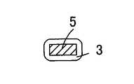
図2は図1のA−A部の断面図で、3は絶縁被覆、4は導体30の結合部を示す。また、図3は図1のB−B部の断面図で、3は絶縁被覆、4は導体30の結合部、5は導体30の首部を示す。図4は図1のC−C部の断面図で、3は絶縁被覆、5は導体30の首部を示す。 FIG. 2 is a cross-sectional view taken along line AA in FIG. 3 is a cross-sectional view taken along the line B-B in FIG. 1, 3 is an insulating coating, 4 is a coupling portion of the
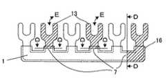
図5は、後述する図7に示すような端子台8の実使用例に対応した短絡板を製作するため、図1の短絡板を切断加工する箇所を示す図面で、13および16のハッチングがほどこされている箇所は切断部で、7は切断部13,16の切断箇所を示し、切断加工時に、図中D−D部をニッパ等によって切断する。 FIG. 5 is a diagram showing a portion for cutting the short-circuit plate in FIG. 1 in order to manufacture a short-circuit plate corresponding to an actual use example of the
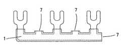
図6は、図1の短絡板1を実使用例に対応させるために加工した短絡板を示す図面で、図5の切断部13の切断箇所7の切断面は、図1のC−C部の断面図である図4と同じ構成を有している。図5の切断部16の切断箇所7の切断面は、図1のA−A部の断面図である図2と同じ構成を有している。いずれの切断面も、図2および図4に示されるように、導体部分が絶縁被覆3と同一面となり、導体が露出している状態となり、その部分は絶縁されていない状態となる。 FIG. 6 is a drawing showing a short-circuit plate processed so as to correspond to the actual use example of the short-
図7は、端子台8に、図6に示した実使用例に対応するように切断加工された短絡板1と電線15と圧着端子12で圧着したケーブルとを接続した例を示す図面である。なお、端子台8は、モールド基台11(図示せず、図8参照)と、モールド基台11上に設けられた端子台導体部10と、端子台導体部10と圧着端子12または短絡板1の接続部2とを固定する端子ネジ9とから構成されている。 FIG. 7 is a diagram showing an example in which the short-
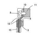
図8は、図7のF−F部の断面図である。図8に示すように、ニッパ等によって切断した短絡板1の図5に示した切断部13を切断した切断箇所7の切断面は、図1のC−C部の断面図と同じで図4の断面図のようになり、首部5からなる導体部分が絶縁被覆3と同一面となり、導体が露出している。そのため、圧着端子12の導体部と首部5との絶縁距離が絶縁被覆3の厚みだけとなり、近接してしまうという問題点があった。 FIG. 8 is a cross-sectional view taken along the line FF in FIG. As shown in FIG. 8, the cut surface of the
このため、従来においては、中間の端子をまたがって短絡板により端子台の端子を接続する場合には、中間の端子部と首部の導体が無く、しかも、その中間の端子部と首部とが設けられていない部分の結合部が絶縁被覆に覆われている専用の短絡板を用いるか、あるいは、上述のように、接続しない導体の接続部を首部で切断加工した短絡板を使用する場合は、導体部分が切断面で露出してしまうため、圧着端子として、絶縁スリーブ付の絶縁付圧着端子を用いて配線する必要があった。 For this reason, in the past, when connecting the terminal of the terminal block across the intermediate terminal by the short-circuit plate, there is no intermediate terminal part and neck conductor, and the intermediate terminal part and neck part are provided. When using a dedicated short-circuit plate in which the coupling portion of the part that is not covered is covered with an insulating coating, or using a short-circuit plate in which the connection portion of the conductor that is not connected is cut at the neck as described above, Since the conductor portion is exposed at the cut surface, it is necessary to perform wiring by using an insulation crimp terminal with an insulation sleeve as the crimp terminal.
また、多極の短絡板から所定の極数の短絡板を切断加工して製作する場合、切断加工した結合部の導体切断面が絶縁物で覆われていないので、絶縁する必要があるという問題点があった。 In addition, when a short-circuit plate having a predetermined number of poles is cut from a multi-pole short-circuit plate, the conductor cut surface of the cut joint portion is not covered with an insulator, so it is necessary to insulate There was a point.
上述したように、従来においては、電気機器の端子台で中間の端子をまたがって短絡板により端子台の端子を接続して、またがった中間の端子から圧着端子により電線を接続する場合には、中間の端子部と首部とが設けられておらず、しかも、その中間の端子部と首部が設けられていない部分の結合部が絶縁被覆に覆われた専用の短絡板を用いて接続する方法が用いられていた。この場合、中間の端子をまたがる端子の数に応じて、それぞれ専用の短絡板を用意する必要があり、手間が非常にかかる上に、大量生産ができないため、コスト面でも大きな問題があった。 As described above, in the past, when connecting the terminal of the terminal block by the short-circuit plate across the intermediate terminal in the terminal block of the electrical equipment, and connecting the electric wire from the intermediate terminal across the crimp terminal, There is a method in which the intermediate terminal portion and the neck portion are not provided, and the connecting portion of the portion where the intermediate terminal portion and the neck portion are not provided is connected using a dedicated short-circuit plate covered with an insulating coating. It was used. In this case, it is necessary to prepare a dedicated short-circuit plate according to the number of terminals straddling the intermediate terminals, which is very troublesome and cannot be mass-produced, resulting in a large cost problem.
また、接続しない端子を切断した短絡板を使用する場合は、短絡板の切断した導体部が圧着端子の金属部分に接触しないようにするため、絶縁スリーブ付の絶縁圧着端子を用いて配線しなければならないという問題点があった。 In addition, when using a short-circuit plate with a terminal that is not connected cut, the insulated conductor with the insulation sleeve must be used for wiring so that the cut conductor of the short-circuit board does not contact the metal part of the crimp terminal. There was a problem of having to.
また、多極の短絡板から所定の極数の短絡板を切断加工して製作する場合、加工した切断面が絶縁物で覆われていないので、その部分が外部に露出してしまうという問題点があった。 In addition, when a short circuit plate having a predetermined number of poles is cut from a multipolar short circuit plate and manufactured, the processed cut surface is not covered with an insulator, so that the part is exposed to the outside. was there.
この発明は、かかる問題点を解決するためになされたものであり、短絡板の使用しない部分を切断した場合にも、切断箇所の導体部分を絶縁被覆の先端から内側にすることを可能にし、従来必要であった専用の短絡板を製作する手間を大幅に削減し、容易に種々の端子台に対応可能で、安価で、かつ、絶縁状態が良好な短絡板を得ることを目的としている。 This invention was made to solve such a problem, and even when the unused portion of the short-circuit plate is cut, it is possible to make the conductor portion of the cut portion inside from the tip of the insulation coating, The purpose of the present invention is to obtain a short-circuit plate that can be easily applied to various terminal blocks, is inexpensive, and has a good insulation state, by greatly reducing the labor required to manufacture a dedicated short-circuit plate that has been necessary in the past.
この発明は、端子台に設けられた異なる端子同士を接続するための短絡板であって、前記端子とそれぞれ1対1に接続される複数の接続部と、前記接続部の下部を一体的に結合するための結合部と、前記接続部と前記結合部との間に設けられた首部とから構成される導体と、前記導体の前記結合部をコーティングして絶縁するとともに、前記導体の前記首部の少なくとも一部分をコーティングして絶縁する絶縁被覆と、前記首部を所定の位置で切断するために、前記首部の一部を前記首部の他の部分よりも薄くして形成するとともに、前記絶縁被覆でコーティングした首部カッティングラインとを備え、前記首部カッティングラインを覆った前記絶縁被覆を残したまま、前記首部カッティングラインの位置から前記首部を切断することを特徴とする短絡板である。This invention provides a short-circuiting plate for connecting the different terminalsare provided in the terminal block, anda plurality of connecting portions to be connectedto the terminalsand respectively one to one, the lower the integrally of the connecting portion A conductor composed of a coupling portion for coupling; a neck portion provided between the connection portion and the coupling portion; and coating and insulating the coupling portion of the conductor; and the neck portion of the conductor An insulating coating that coats and insulates at least a portion of the neck portion, and in order to cut the neck portion at a predetermined position, a part of the neck portion is made thinner than other portions of the neck portion, and the insulating coating A neck cutting line that is coated, and the neck is cut from the position of the neck cutting line while leaving the insulating coating covering the neck cutting line. It is a short-circuit plate for.
この発明は、端子台に設けられた異なる端子同士を接続するための短絡板であって、前記端子とそれぞれ1対1に接続される複数の接続部と、前記接続部の下部を一体的に結合するための結合部と、前記接続部と前記結合部との間に設けられた首部とから構成される導体と、前記導体の前記結合部をコーティングして絶縁するとともに、前記導体の前記首部の少なくとも一部分をコーティングして絶縁する絶縁被覆と、前記首部を所定の位置で切断するために、前記首部の一部を前記首部の他の部分よりも薄くして形成するとともに、前記絶縁被覆でコーティングした首部カッティングラインとを備え、前記首部カッティングラインを覆った前記絶縁被覆を残したまま、前記首部カッティングラインの位置から前記首部を切断することを特徴とする短絡板であるので、ので、短絡板の使用しない部分を切断した場合にも、切断箇所の導体部分を絶縁被覆の先端から内側にすることを可能にし、従来必要であった専用の短絡板を製作する手間を大幅に削減し、容易に種々の端子台に対応可能で、安価で、かつ、絶縁状態が良好な短絡板を得ることができる。This invention provides a short-circuiting plate for connecting the different terminalsare provided in the terminal block, anda plurality of connecting portions to be connectedto the terminalsand respectively one to one, the lower the integrally of the connecting portion A conductor composed of a coupling portion for coupling; a neck portion provided between the connection portion and the coupling portion; and coating and insulating the coupling portion of the conductor; and the neck portion of the conductor An insulating coating that coats and insulates at least a portion of the neck portion, and in order to cut the neck portion at a predetermined position, a part of the neck portion is made thinner than other portions of the neck portion, and the insulating coating A neck cutting line that is coated, and the neck is cut from the position of the neck cutting line while leaving the insulating coating covering the neck cutting line. Therefore, even when the unused part of the shorting plate is cut, it is possible to make the conductor part of the cutting part inside from the tip of the insulation coating, and the dedicated shorting plate that was necessary in the past Therefore, it is possible to obtain a short-circuit plate that can be easily applied to various terminal blocks, is inexpensive, and has a good insulation state.
実施の形態1.
本発明の実施の形態について説明する。
図9は本発明の実施の形態1に係る短絡板の構成を示した図である。短絡板1は、接続部2と結合部4と首部5とからなる導体30と絶縁被覆3とから構成されている。基本的な構成は、図1に示した従来の短絡板と同じであるため、ここでは詳細な説明は省略し、異なる構成を主に説明する。
Embodiments of the present invention will be described.
FIG. 9 is a diagram showing a configuration of the short-circuit plate according to
図9において、6と14は、本実施の形態における導体30のカッティングラインで、6は、首部5に設けられ、首部5を所定の位置で切断しやすくするための首部カッティングラインで、14は、首部5から結合部4にかけて設けられ、結合部4を所定の位置で切断しやすくするための結合部カッティングラインである。なお、絶縁被覆3は、結合部4をコーティングして絶縁するとともに、首部5に沿って延びていて、首部5の少なくとも一部分をコーティングして絶縁している。また、首部カッティングライン6は、そのように首部5に沿って延びた絶縁被覆3の端面(先端)よりも内側の位置に形成されている。本実施の形態に係る導体30には、このように、導体30の所定の箇所を切断しやすくし、かつ、切断箇所の絶縁被覆3の厚みが他の箇所に比べて厚くなり、切断箇所の絶縁状態を良好にすることを可能にするカッティングラインが複数設けられている。以下、詳細に説明する。 In FIG. 9, 6 and 14 are cutting lines of the
図10は、図9のG−G部の断面図で、3は絶縁被覆、4は導体30の結合部、5は導体30の首部、6は首部カッティングラインである。首部カッティングライン6は、図10に示すように、結合部4や首部5に比べて、厚みが薄く、細くなるように形成されている。従って、首部カッティングライン6の箇所においては、絶縁被覆3が、他の部分に比べて、厚みが厚く、首部5の内側に入り込んだ状態となっている。尚、首部カッティングライン6については、本実施の形態においては、首部5の両面にV字型の溝を入れて形成しているが、その場合に限らず、首部5の一方の面にだけ形成するようにしてもよい。またV字型以外の例えばU字型や矩形型の形状の溝でもよく、本実施の形態における首部カッティングライン6と同様な効果が得られるカッティングラインであればいずれの形状のものでもよい。 FIG. 10 is a cross-sectional view of the GG portion of FIG. 9, wherein 3 is an insulating coating, 4 is a coupling portion of the
図11は、図9のH−H部の断面図で、3は絶縁被覆、4は導体30の結合部、14は結合部4を所定の位置で切断しやすくするための結合部カッティングラインを示す。図11に示すように、結合部4と結合部カッティングライン14とは絶縁被覆3により覆われている。結合部カッティングライン14は、図11に示すように、結合部4の他の部分に比べて、厚みが薄くなるように形成されている。従って、結合部カッティングライン14の箇所においては、絶縁被覆3が、他の部分に比べて、厚みが厚く、結合部4の内側に入り込んだ状態となっている。尚、結合部カッティングライン14については、本実施の形態においては、結合部4の両面にV字型の溝を入れて形成しているが、その場合に限らず、結合部4の一方の面にだけ形成するようにしてもよい。またV字型以外の例えばU字型や矩形型の形状の溝でもよく、本実施の形態における結合部カッティングライン14と同様な効果が得られるカッティングラインであればいずれの形状のものでもよい。 FIG. 11 is a cross-sectional view taken along the line H-H in FIG. 9, wherein 3 is an insulation coating, 4 is a coupling portion of the
図12は、後述する図14の端子台8の実使用例に対応させた短絡板を製作するため、図9の短絡板1を切断加工する箇所を示す図面で、17,18,19のハッチングを施した部分は切断加工により切除される切断部を示す。7は、切断部17と切断部18とを切断する切断箇所を示している。なお、結合部カッティングライン14は切断箇所7よりも内側の位置に形成されている。また、18は、切断箇所7から切断部17を切断したときに、絶縁被覆3内に残る切断部である。切断部17および18の切断加工においては、まず、切断部17部分を切除するために、切断箇所7において、絶縁被覆3とその中の結合部4を構成している導体部分とをニッパ等によって同時に切断して切除する。その後、絶縁被覆3内に残っている切断部18部分を手またはラジオペンチ等でつかみ、反対側を手またはペンチ等により水平に固定して、切断部18部分をつかんだ手またはラジオペンチを矢印J方向に上下に動かして、結合部カッティングライン14の上下方向への折り曲げを繰り返し行うことにより、結合部カッティングライン14を切断し、切断部18を切除する。なお、このとき、切断部18部分だけでなく、絶縁被覆3ごと切断部18部分を手またはラジオペンチ等でつかんで上述の折り曲げ動作を行ってもよく、その場合においても、絶縁被覆3は柔軟性を有しているため、上述の折り曲げ動作によって破損するようなことはない。また、切断部19の切断加工においては、首部カッティングライン6が外部に近い位置にあり、切断箇所7のように完全に絶縁被覆3で覆われている訳ではないので、上述したニッパ等による切断作業は不要であり、単に、切断部19部分を手またはラジオペンチ等でつかみ、反対側を手またはペンチ等により水平に固定して、切断部19部分をつかんだ手またはラジオペンチを矢印J方向に上下に動かして、首部カッティングライン6の上下方向への折り曲げを繰り返し行うことにより、首部カッティングライン6を切断し、切断部19を切除する。首部カッティングライン6および結合部カッティングライン14は、他の部分に比べて、厚みが薄く、細く形成されているので、上記の折り曲げ動作により、容易に、かつ、きれいにその部分から切断される。 FIG. 12 is a diagram showing a location where the short-
図13は、図9の短絡板1を実使用例に対応させて切断加工した短絡板を示す図面である。上述したように、絶縁被覆3は切断箇所7の位置で切断され、導体30は切断箇所7よりも内側に位置する首部カッティングライン6および結合部カッティングライン14の位置で切断されるので、切断した首部カッティングライン6と結合部カッティングライン14における導体切断面が絶縁被覆3の端面より内側に入ることになる。当該導体切断面と絶縁被覆3の端面(先端)との距離は、当該導体切断面が他の部材に接触することを防止し、それらから絶縁するために十分な距離になるように構成されているので、従って、当該導体切断面は絶縁被覆3によって絶縁され、短絡板1を電気機器の端子台等に装着した場合に、良好な絶縁状態が確保されることがわかる。 FIG. 13 is a drawing showing a short-circuit plate obtained by cutting the short-
なお、本実施の形態における絶縁被覆3は柔軟性を有しており、切断箇所7においては、当該柔軟性により、絶縁被覆3の切断面が切断箇所7よりもわずかに盛り上がるとともに、上側の絶縁被覆3と下側の絶縁被覆3とが互いに若干接近し、その結果、導体切断面は絶縁被覆3の中に埋没した状態となるので、絶縁被覆3が何らかの原因によってめくれてしまい導体切断面が外部に露出されるようなことはない。なお、絶縁被覆3は弾力性を有していてもよい。 The insulating
このように、本実施の形態は、端子台に設けられた異なる端子を接続するための短絡板であって、端子台8の端子に接続される1以上の接続部2と、接続部2の下部を一体的に結合するための結合部4と、接続部2と結合部4との間に設けられた首部5とから構成される導体30と、導体30の結合部4をコーティングして絶縁するとともに、導体30の首部5の少なくとも一部をコーティングして絶縁する絶縁被覆3と、首部5を所定の位置で切断するために、首部5の一部を首部5の他の部分よりも薄くなるように形成した首部カッティングライン6とを備え、当該首部カッティングライン6は、絶縁被覆3でコーティングされ、首部5を切断する場合には、首部カッティングライン6を覆った部分の絶縁被覆3を残したまま、首部カッティングライン6の位置から首部5を切断する構成を有している。さらに、本実施の形態においては、導体30の結合部4を所定の位置で切断するために、結合部4の一部を結合部4の他の部分よりも薄くなるように形成した結合部カッティングライン14を備え、結合部4を切断する場合には、結合部カッティングライン14を覆った部分の絶縁被覆3を残したまま、結合部カッティングライン14の位置から結合部4を切断する構成を有している。なお、本実施の形態においては、首部カッティングライン6と結合部カッティングライン14とを両方設けた例について説明したが、その場合に限らず、いずれか一方のみを設けるようにしてもよい。 Thus, this Embodiment is a short circuit board for connecting the different terminal provided in the terminal block, Comprising: One or
図14は、モールド基台11(図示せず、図15参照)と端子台導体部10と端子ネジ9とから構成される端子台8に対して、図13に示す実使用例に対応させて切断加工した短絡板1と、電線15を圧着端子12で圧着したケーブル20とを接続させた実施例を示した図である。 14 corresponds to the actual use example shown in FIG. 13 for the
図15は、図14のK−K部の断面図を示す図面であり、図15に示すように、圧着端子12の導体部分と絶縁被覆3より内側に入った首部カッティングライン6の導体切断面とが絶縁被覆3により絶縁状態を確保するのに十分な絶縁距離を確保していることがわかる。 15 is a cross-sectional view of the KK portion of FIG. 14, and as shown in FIG. 15, the conductor cut surface of the
以上のように、本実施の形態においては、短絡板1から接続に使用しない不要な部分を切断するための首部カッティングライン6および結合部カッティングライン14を設け、それらのカッティングラインを柔軟性のある絶縁被覆3で覆い、覆った絶縁被覆3をカッティングラインよりも長めに残した状態で、絶縁被覆3内にある導体をカッティングラインで切断して取り除くことができる構成にした。その結果、不要な部分を切断したときに、絶縁被覆3の切断面の方が導体部分の切断面よりも外側になって、導体部分が露出されることなく説線被覆3で覆われ、導体部分の切断面が絶縁被覆3の切断面の内側に埋没するように切断できるので、絶縁被覆3の切断面から内側にある導体部分の切断面までの絶縁距離が絶縁に十分な寸法を確保して切断できる。従って、本実施の形態による短絡板を予め用意しておくことにより、上述したような各種仕様の短絡板を容易に切断加工して製作することができる。これにより、従来のように種々の専用の短絡板をいくつも予め用意する必要をなくし、それらの専用の短絡板を製作するために従来必要であった手間を大幅に削減し、容易に製作でき、しかも、大量生産を可能にしたため、安価で、かつ、絶縁状態が良好な短絡板を得ることができる。 As described above, in the present embodiment, the
1 短絡板、2 接続部、3 絶縁被覆、4 結合部、5 首部、6 首部カッティングライン、7 切断箇所、8 端子台、9 端子ネジ、10 端子台導体部、11 モールド基台、12 圧着端子、13 切断部、14 結合部カッティングライン、15 電線、16 切断部、17 切断部、18 切断部、19 切断部、20 ケーブル、30 導体。 DESCRIPTION OF
Claims (3)
Translated fromJapanese前記端子とそれぞれ1対1に接続される複数の接続部と、前記接続部の下部を一体的に結合するための結合部と、前記接続部と前記結合部との間に設けられた首部とから構成される導体と、
前記導体の前記結合部をコーティングして絶縁するとともに、前記導体の前記首部の少なくとも一部分をコーティングして絶縁する絶縁被覆と、
前記首部を所定の位置で切断するために、前記首部の一部を前記首部の他の部分よりも薄くして形成するとともに、前記絶縁被覆でコーティングした首部カッティングラインと
を備え、
前記首部カッティングラインを覆った前記絶縁被覆を残したまま、前記首部カッティングラインの位置から前記首部を切断することを特徴とする短絡板。A short circuit plate for connecting the different terminalsare provided in the terminal block,
Aplurality of connecting portions to be connectedto the terminalsand respectively one to one, and the connecting portion coupling portion for integrally coupling the lower portion of a neck portion provided between said connecting portion and the coupling portion A conductor composed of
An insulating coating that coats and insulates the coupling portion of the conductor and coats and insulates at least a portion of the neck of the conductor;
In order to cut the neck at a predetermined position, a part of the neck is formed thinner than the other part of the neck, and a neck cutting line coated with the insulating coating is provided.
A short-circuit plate, wherein the neck is cut from the position of the neck cutting line while leaving the insulating coating covering the neck cutting line.
前記端子とそれぞれ1対1に接続される複数の接続部と、前記接続部の下部を一体的に結合するための結合部と、前記接続部と前記結合部との間に設けられた首部とから構成される導体と、
前記導体の前記結合部をコーティングして絶縁する絶縁被覆と、
前記結合部を所定の位置で切断するために、前記結合部の一部を前記結合部の他の部分よりも薄くして形成した結合部カッティングラインと
を備え、
前記結合部カッティングラインを覆った前記絶縁被覆を残したまま、前記結合部カッティングラインの位置から前記結合部を切断することを特徴とする短絡板。A short circuit plate for connecting the different terminalsare provided in the terminal block,
Aplurality of connecting portions to be connectedto the terminalsand respectively one to one, and the connecting portion coupling portion for integrally coupling the lower portion of a neck portion provided between said connecting portion and the coupling portion A conductor composed of
An insulation coating that insulates and coats the joint of the conductor;
In order to cut the coupling part at a predetermined position, a coupling part cutting line formed by making a part of the coupling part thinner than other parts of the coupling part, and
A short-circuit plate, wherein the coupling portion is cut from a position of the coupling portion cutting line while leaving the insulating coating covering the coupling portion cutting line.
前記端子とそれぞれ1対1に接続される複数の接続部と、前記接続部の下部を一体的に結合するための結合部と、前記接続部と前記結合部との間に設けられた首部とから構成される導体と、
前記導体の前記結合部をコーティングして絶縁するとともに、前記導体の前記首部の少なくとも一部分をコーティングして絶縁する絶縁被覆と、
前記首部を所定の位置で切断するために、前記首部の一部を前記首部の他の部分よりも薄くして形成するとともに、前記絶縁被覆でコーティングした首部カッティングラインと、
前記結合部を所定の位置で切断するために、前記結合部の一部を前記結合部の他の部分よりも薄くして形成するとともに、前記絶縁被覆でコーティングした結合部カッティングラインと
を備え、
前記首部を切断する場合には、前記首部カッティングラインを覆った前記絶縁被覆を残したまま、前記首部カッティングラインの位置から前記首部を切断し、
前記結合部を切断する場合には、前記結合部カッティングラインを覆った前記絶縁被覆を残したまま、前記結合部カッティングラインの位置から前記結合部を切断する
ことを特徴とする短絡板。A short circuit plate for connecting the different terminalsare provided in the terminal block,
Aplurality of connecting portions to be connectedto the terminalsand respectively one to one, and the connecting portion coupling portion for integrally coupling the lower portion of a neck portion provided between said connecting portion and the coupling portion A conductor composed of
An insulating coating that coats and insulates the coupling portion of the conductor and coats and insulates at least a portion of the neck of the conductor;
In order to cut the neck at a predetermined position, a part of the neck is formed thinner than the other part of the neck, and a neck cutting line coated with the insulating coating is formed.
In order to cut the joint at a predetermined position, a part of the joint is formed thinner than the other part of the joint, and a joint cutting line coated with the insulating coating is provided.
When cutting the neck, cutting the neck from the position of the neck cutting line, leaving the insulating coating covering the neck cutting line,
A short-circuit plate, wherein, when cutting the joint, the joint is cut from the position of the joint cutting line while leaving the insulating coating covering the joint cutting line.
Priority Applications (1)
| Application Number | Priority Date | Filing Date | Title |
|---|---|---|---|
| JP2007283580AJP4355742B2 (en) | 2007-10-31 | 2007-10-31 | Short-circuit plate |
Applications Claiming Priority (1)
| Application Number | Priority Date | Filing Date | Title |
|---|---|---|---|
| JP2007283580AJP4355742B2 (en) | 2007-10-31 | 2007-10-31 | Short-circuit plate |
Publications (2)
| Publication Number | Publication Date |
|---|---|
| JP2009110868A JP2009110868A (en) | 2009-05-21 |
| JP4355742B2true JP4355742B2 (en) | 2009-11-04 |
Family
ID=40779123
Family Applications (1)
| Application Number | Title | Priority Date | Filing Date |
|---|---|---|---|
| JP2007283580AActiveJP4355742B2 (en) | 2007-10-31 | 2007-10-31 | Short-circuit plate |
Country Status (1)
| Country | Link |
|---|---|
| JP (1) | JP4355742B2 (en) |
Families Citing this family (6)
| Publication number | Priority date | Publication date | Assignee | Title |
|---|---|---|---|---|
| JP2011159404A (en)* | 2010-01-29 | 2011-08-18 | Nikkiso Co Ltd | Short circuit plate for short-circuiting terminal of terminal block |
| US9366879B1 (en) | 2014-12-02 | 2016-06-14 | Hutchinson Technology Incorporated | Camera lens suspension with polymer bearings |
| US9454016B1 (en) | 2015-03-06 | 2016-09-27 | Hutchinson Technology Incorporated | Camera lens suspension with integrated electrical leads |
| KR101693030B1 (en)* | 2016-04-25 | 2017-01-05 | 문성모 | Short bar for terminal block |
| GB2570481B (en)* | 2018-01-26 | 2020-12-09 | Goodridge Richard | A connector device |
| JP2022136828A (en)* | 2021-03-08 | 2022-09-21 | オムロン株式会社 | Short circuit member |
- 2007
- 2007-10-31JPJP2007283580Apatent/JP4355742B2/enactiveActive
Also Published As
| Publication number | Publication date |
|---|---|
| JP2009110868A (en) | 2009-05-21 |
Similar Documents
| Publication | Publication Date | Title |
|---|---|---|
| CN103855542B (en) | Cable connector, cable assembly, and method of manufacturing the cable assembly | |
| US10756592B2 (en) | Contacting arrangement between a stator and a circuit board | |
| JP4355742B2 (en) | Short-circuit plate | |
| JP2010094014A (en) | Electric motor interface, electric plug component therefor, electric motor terminal, and electric motor | |
| CN105393648A (en) | Printed circuit boards with side-entry termination pads | |
| KR101643218B1 (en) | Terminal for connector and connector having the same | |
| CN112856266B (en) | A flexible LED light strip, connecting conductor, and connecting conductor array | |
| ES2210949T3 (en) | ELECTRICAL CONNECTION TERMINAL. | |
| JP5822598B2 (en) | Terminal connection structure used for small electrical parts | |
| JP2004039380A (en) | Pressure contact terminal and electric connection box using the pressure contact terminal | |
| JP2003016850A (en) | Flat circuit body and method of manufacturing the same | |
| JP2013059137A (en) | Relay | |
| JP4070114B2 (en) | Flat cable connection structure | |
| JP2006221863A (en) | Electrical connector for cable and method for manufacturing the same | |
| JP7431091B2 (en) | Connecting terminal | |
| WO2015064667A1 (en) | Litz wire terminal | |
| JPH025485Y2 (en) | ||
| KR20130006093U (en) | Multi joint terminal | |
| JP2015065027A (en) | Component for splice | |
| KR200394072Y1 (en) | A terminal for an electric wire connection | |
| JP2007123104A (en) | Connector for coaxial cable | |
| JP2025085887A (en) | Manufacturing method of plug | |
| EP3182518B1 (en) | Electrical connector | |
| WO1996027220A1 (en) | A method for connection of insulated conductors to a connection member | |
| JP2006332005A (en) | Connector for electric wire |
Legal Events
| Date | Code | Title | Description |
|---|---|---|---|
| A621 | Written request for application examination | Free format text:JAPANESE INTERMEDIATE CODE: A621 Effective date:20090227 | |
| A871 | Explanation of circumstances concerning accelerated examination | Free format text:JAPANESE INTERMEDIATE CODE: A871 Effective date:20090402 | |
| A975 | Report on accelerated examination | Free format text:JAPANESE INTERMEDIATE CODE: A971005 Effective date:20090415 | |
| A131 | Notification of reasons for refusal | Free format text:JAPANESE INTERMEDIATE CODE: A131 Effective date:20090507 | |
| A521 | Request for written amendment filed | Free format text:JAPANESE INTERMEDIATE CODE: A523 Effective date:20090618 | |
| TRDD | Decision of grant or rejection written | ||
| A01 | Written decision to grant a patent or to grant a registration (utility model) | Free format text:JAPANESE INTERMEDIATE CODE: A01 Effective date:20090714 | |
| A01 | Written decision to grant a patent or to grant a registration (utility model) | Free format text:JAPANESE INTERMEDIATE CODE: A01 | |
| A61 | First payment of annual fees (during grant procedure) | Free format text:JAPANESE INTERMEDIATE CODE: A61 Effective date:20090803 | |
| R150 | Certificate of patent or registration of utility model | Free format text:JAPANESE INTERMEDIATE CODE: R150 Ref document number:4355742 Country of ref document:JP | |
| FPAY | Renewal fee payment (event date is renewal date of database) | Free format text:PAYMENT UNTIL: 20120807 Year of fee payment:3 | |
| FPAY | Renewal fee payment (event date is renewal date of database) | Free format text:PAYMENT UNTIL: 20120807 Year of fee payment:3 | |
| FPAY | Renewal fee payment (event date is renewal date of database) | Free format text:PAYMENT UNTIL: 20130807 Year of fee payment:4 | |
| R250 | Receipt of annual fees | Free format text:JAPANESE INTERMEDIATE CODE: R250 | |
| R250 | Receipt of annual fees | Free format text:JAPANESE INTERMEDIATE CODE: R250 | |
| R250 | Receipt of annual fees | Free format text:JAPANESE INTERMEDIATE CODE: R250 | |
| R250 | Receipt of annual fees | Free format text:JAPANESE INTERMEDIATE CODE: R250 | |
| R250 | Receipt of annual fees | Free format text:JAPANESE INTERMEDIATE CODE: R250 | |
| R250 | Receipt of annual fees | Free format text:JAPANESE INTERMEDIATE CODE: R250 | |
| R250 | Receipt of annual fees | Free format text:JAPANESE INTERMEDIATE CODE: R250 | |
| R250 | Receipt of annual fees | Free format text:JAPANESE INTERMEDIATE CODE: R250 | |
| R250 | Receipt of annual fees | Free format text:JAPANESE INTERMEDIATE CODE: R250 | |
| R250 | Receipt of annual fees | Free format text:JAPANESE INTERMEDIATE CODE: R250 | |
| R250 | Receipt of annual fees | Free format text:JAPANESE INTERMEDIATE CODE: R250 | |
| R250 | Receipt of annual fees | Free format text:JAPANESE INTERMEDIATE CODE: R250 | |
| R250 | Receipt of annual fees | Free format text:JAPANESE INTERMEDIATE CODE: R250 | |
| R250 | Receipt of annual fees | Free format text:JAPANESE INTERMEDIATE CODE: R250 |