JP4354949B2 - Long-distance steerable catheter actuator - Google Patents
Long-distance steerable catheter actuatorDownload PDFInfo
- Publication number
- JP4354949B2 JP4354949B2JP2005378452AJP2005378452AJP4354949B2JP 4354949 B2JP4354949 B2JP 4354949B2JP 2005378452 AJP2005378452 AJP 2005378452AJP 2005378452 AJP2005378452 AJP 2005378452AJP 4354949 B2JP4354949 B2JP 4354949B2
- Authority
- JP
- Japan
- Prior art keywords
- actuator
- handle
- wire
- gear
- assembly
- Prior art date
- Legal status (The legal status is an assumption and is not a legal conclusion. Google has not performed a legal analysis and makes no representation as to the accuracy of the status listed.)
- Active
Links
- 238000007674radiofrequency ablationMethods0.000abstractdescription5
- 230000007831electrophysiologyEffects0.000abstractdescription2
- 238000002001electrophysiologyMethods0.000abstractdescription2
- 238000006073displacement reactionMethods0.000description13
- 230000006835compressionEffects0.000description8
- 238000007906compressionMethods0.000description8
- 238000000034methodMethods0.000description5
- 210000003811fingerAnatomy0.000description3
- 238000012544monitoring processMethods0.000description3
- 239000004677NylonSubstances0.000description2
- 230000000712assemblyEffects0.000description2
- 238000000429assemblyMethods0.000description2
- 238000013507mappingMethods0.000description2
- 229920001778nylonPolymers0.000description2
- 229920002635polyurethanePolymers0.000description2
- 239000004814polyurethaneSubstances0.000description2
- 230000002787reinforcementEffects0.000description2
- 230000003014reinforcing effectEffects0.000description2
- 210000003813thumbAnatomy0.000description2
- 229920000914Metallic fiberPolymers0.000description1
- 229910000831SteelInorganic materials0.000description1
- 239000008280bloodSubstances0.000description1
- 210000004369bloodAnatomy0.000description1
- 238000006243chemical reactionMethods0.000description1
- 230000000694effectsEffects0.000description1
- 210000005224forefingerAnatomy0.000description1
- 239000000463materialSubstances0.000description1
- 230000013011matingEffects0.000description1
- 238000012986modificationMethods0.000description1
- 230000004048modificationEffects0.000description1
- 238000012806monitoring deviceMethods0.000description1
- HLXZNVUGXRDIFK-UHFFFAOYSA-Nnickel titaniumChemical compound[Ti].[Ti].[Ti].[Ti].[Ti].[Ti].[Ti].[Ti].[Ti].[Ti].[Ti].[Ni].[Ni].[Ni].[Ni].[Ni].[Ni].[Ni].[Ni].[Ni].[Ni].[Ni].[Ni].[Ni].[Ni]HLXZNVUGXRDIFK-UHFFFAOYSA-N0.000description1
- 229910001000nickel titaniumInorganic materials0.000description1
- 239000012811non-conductive materialSubstances0.000description1
- 230000037361pathwayEffects0.000description1
- 230000002093peripheral effectEffects0.000description1
- 239000010959steelSubstances0.000description1
- 238000004804windingMethods0.000description1
Images


Classifications
- A—HUMAN NECESSITIES
- A61—MEDICAL OR VETERINARY SCIENCE; HYGIENE
- A61M—DEVICES FOR INTRODUCING MEDIA INTO, OR ONTO, THE BODY; DEVICES FOR TRANSDUCING BODY MEDIA OR FOR TAKING MEDIA FROM THE BODY; DEVICES FOR PRODUCING OR ENDING SLEEP OR STUPOR
- A61M25/00—Catheters; Hollow probes
- A61M25/01—Introducing, guiding, advancing, emplacing or holding catheters
- A61M25/0105—Steering means as part of the catheter or advancing means; Markers for positioning
- A61M25/0133—Tip steering devices
- A61M25/0147—Tip steering devices with movable mechanical means, e.g. pull wires
- A—HUMAN NECESSITIES
- A61—MEDICAL OR VETERINARY SCIENCE; HYGIENE
- A61M—DEVICES FOR INTRODUCING MEDIA INTO, OR ONTO, THE BODY; DEVICES FOR TRANSDUCING BODY MEDIA OR FOR TAKING MEDIA FROM THE BODY; DEVICES FOR PRODUCING OR ENDING SLEEP OR STUPOR
- A61M25/00—Catheters; Hollow probes
- A61M25/01—Introducing, guiding, advancing, emplacing or holding catheters
- A61M25/0105—Steering means as part of the catheter or advancing means; Markers for positioning
- A61M25/0133—Tip steering devices
- A61M25/0136—Handles therefor
Landscapes
- Health & Medical Sciences (AREA)
- Life Sciences & Earth Sciences (AREA)
- Engineering & Computer Science (AREA)
- Hematology (AREA)
- General Health & Medical Sciences (AREA)
- Anesthesiology (AREA)
- Biomedical Technology (AREA)
- Heart & Thoracic Surgery (AREA)
- Biophysics (AREA)
- Animal Behavior & Ethology (AREA)
- Pulmonology (AREA)
- Public Health (AREA)
- Veterinary Medicine (AREA)
- Mechanical Engineering (AREA)
- Media Introduction/Drainage Providing Device (AREA)
- Surgical Instruments (AREA)
- Materials For Medical Uses (AREA)
Abstract
Description
Translated fromJapanese本発明は、カテーテル及びシース、並びに、該カテーテル及びシースを使用する方法に関する。より詳しくは、本発明は、操舵可能なカテーテル及びシースのための制御ハンドル、並びに、そのようなハンドルを製造、使用する方法に関する。 The present invention relates to catheters and sheaths and methods of using the catheters and sheaths. More particularly, the present invention relates to control handles for steerable catheters and sheaths, and methods for making and using such handles.
末端部に沿って伝導性電極を有するカテーテル(即ち、カテーテル又はシース)は、一般に心臓内電気生理学的研究のため使用されている。そのようなカテーテルの末端部は、電気生理学的研究の間又は心臓内マッピングの間に心臓内電気信号を監視し及び/又は記録するため、典型的には心臓内に配置されている。カテーテル末端部の配置又は外形は、患者の身体の外部のハンドルに配置されたアクチュエータを介して制御され、電極は、心臓電気信号をカテーテルのハンドルに作動的に取り付けられた適切な監視記録装置に伝達する。 Catheters with conductive electrodes along their ends (ie, catheters or sheaths) are commonly used for intracardiac electrophysiological studies. The distal end of such a catheter is typically placed in the heart for monitoring and / or recording intracardiac electrical signals during electrophysiological studies or intracardiac mapping. The placement or contour of the distal end of the catheter is controlled via an actuator located on a handle external to the patient's body, and the electrodes are connected to a suitable monitoring and recording device operatively attached to the catheter handle. introduce.
典型的には、これらのカテーテルは、略円柱状の非導電性の主要ボディを備えている。主要ボディは、ポリウレタン、ナイロン、又は、他の非導電性の可撓性材料から構成された可撓性チューブである。主要ボディは、補強要素として、その壁内に、編んだ鋼鉄ワイヤ又は他の非金属繊維を更に含んでいる。各々の電極は、該電極に取り付けられ、カテーテルの主要ボディを通って延在する、比較的細い導電性ワイヤを有する。導電性ワイヤは、末端部から基端部まで延在し、該基端部では、例えばプラグ又はジャック等の電気コネクターが、記録又は監視の装置に設けられた対応するソケット内に差し込まれるように設けられている。 Typically, these catheters include a substantially cylindrical non-conductive main body. The main body is a flexible tube constructed from polyurethane, nylon, or other non-conductive flexible material. The main body further includes a braided steel wire or other non-metallic fiber in its wall as a reinforcing element. Each electrode has a relatively thin conductive wire attached to the electrode and extending through the main body of the catheter. The conductive wire extends from the distal end to the proximal end, where an electrical connector such as a plug or jack is plugged into a corresponding socket provided in the recording or monitoring device. Is provided.
主要ボディの末端部は、選択的に、アクチュエータを使用して様々に様々に湾曲した外形へと選択的に歪められる、アクチュエータは、一般に少なくとも1つの作動ワイヤによりカテーテルの末端部に相互連結されている。幾つかのカテーテルは、主要ボディの末端部を歪めさせるため、アクチュエータにより引っ張られる(即ち、張力がかけられた状態に置いた)単一の動作ワイヤを用いている。他のカテーテルは、少なくとも2つの動作ワイヤを持っており、この場合、一方のワイヤの活動(即ち張力がかけられた状態に置くこと)が他方のワイヤの緩み(即ち、ワイヤが圧縮負荷を伝達しない)を生じさせる。動作ワイヤが圧縮負荷を伝達するようには適合されないようなカテーテル(即ち、動作ワイヤは張力がかけられた状態に置かれるのみである)では、動作ワイヤは、一般に、引っ張りワイヤ又は張力ワイヤと称される。 The distal end of the main body is selectively distorted to variously curved contours using an actuator, which is generally interconnected to the distal end of the catheter by at least one actuation wire. Yes. Some catheters use a single working wire that is pulled (ie, placed in tension) by an actuator to distort the distal end of the main body. Other catheters have at least two working wires, where the activity of one wire (ie placing it in tension) causes the other wire to loosen (ie the wire carries a compressive load). Not). In catheters where the working wire is not adapted to transmit a compressive load (ie, the working wire is only placed under tension), the working wire is commonly referred to as a pull wire or tension wire. Is done.
カテーテルの末端部を様々な外形に歪ませるため、より最近のカテーテル設計は、一対の動作ワイヤを用いており、該一対のワイヤは、一方の動作ワイヤが圧縮負荷を伝達し、他方の動作ワイヤが伸長力を伝達するように適合されている。動作ワイヤが圧縮負荷及び張力負荷の両方を伝達するように適合されたカテーテルでは、動作ワイヤは、一般に、押し/引きワイヤ又は張力/圧縮ワイヤと称され、対応するカテーテルアクチュエータは、押し引きアクチュエータと称される。ラシジに対して1999年1月19日に発行された米国特許番号5,861,024号は、この種の押し引きアクチュエータを表しており、その詳細は、参照により本願に組み込まれる。 More recent catheter designs have used a pair of working wires to distort the distal end of the catheter into various outer shapes, one of the working wires carrying a compressive load and the other working wire. Is adapted to transmit an extension force. In catheters where the working wire is adapted to transmit both compression and tension loads, the working wire is commonly referred to as a push / pull wire or tension / compression wire, and the corresponding catheter actuator is a push-pull actuator and Called. U.S. Pat. No. 5,861,024 issued Jan. 19, 1999 to Rashiji represents such a push-pull actuator, the details of which are incorporated herein by reference.
現存するカテーテルアクチュエータの多くは、ボディの末端部の運動に正確な作業及び良好な可撓性を提供するが、現存するアクチュエータは、提供する末端部の変位の範囲が望ましい範囲よりも小さくなっている。換言すれば、動作ワイヤの押し/引きの量(即ち、操舵移動量)は、しばしば、実行されている医療処置にとって不適切となる。操舵移動の不適切さは、典型的には、アクチュエータボディの略限定されたサイズから生じる。該ボディは、通常、使用者の手の親指と人差し指との間の受け取り及び操作のためにサイズが定められている。 Many of the existing catheter actuators provide precise work and good flexibility for the movement of the distal end of the body, but existing actuators provide a range of distal displacement that is less than desired. Yes. In other words, the amount of push / pull of the operating wire (ie, the amount of steering movement) is often inadequate for the medical procedure being performed. Inadequate steering movement typically results from the generally limited size of the actuator body. The body is typically sized for receipt and manipulation between the thumb and forefinger of the user's hand.
従って、アクチュエータに連係した操舵移動量を増大させたカテーテルのために改善された動作アッセンブリを提供する必要性が存在している。 Accordingly, there is a need to provide an improved motion assembly for a catheter with increased steering travel associated with an actuator.
本発明は、一実施形態では、動作ワイヤの移動長さ(即ち、操舵移動量)を有意に増加させるアクチュエータを備える、電気生理学的なRF切除又は類似のカテーテルに関する。本明細書を通して、「カテーテル」という用語は、カテーテル、シース及びこれらに類似した医療装置を含むことが意図されているが、これらに限定されるものではない。 The present invention, in one embodiment, relates to an electrophysiological RF ablation or similar catheter with an actuator that significantly increases the travel length (ie, steering travel) of the working wire. Throughout this specification, the term “catheter” is intended to include, but is not limited to, catheters, sheaths and similar medical devices.
カテーテルは、中空の可撓性管状ボディと、該ボディ内に並列関係で配置された一対の動作ワイヤと、ボディの基端部に取り付けられたハンドルと、該ハンドルに枢動式に取り付けられたアクチュエータと、アクチュエータ上に配置された弧状内側ギアラックと、ハンドルに枢動式に取り付けられ且つギアラックと噛み合うピニオンギアに同軸連結された1つ以上のプーリーと、ハンドル内に取り付けられた案内ブロックと、を備える。 The catheter includes a hollow flexible tubular body, a pair of operating wires disposed in parallel within the body, a handle attached to the proximal end of the body, and pivotally attached to the handle An actuator, an arcuate inner gear rack disposed on the actuator, one or more pulleys pivotally attached to the handle and coaxially connected to a pinion gear that meshes with the gear rack, and a guide block attached within the handle; Is provided.
1つ以上のプーリーは、第1の動作ワイヤが配置された第1のチャンネルと、第2の動作ワイヤが配置された第2のチャンネルと、を備える。動作ワイヤは、案内ブロック内の孔を通過し、該案内ブロックは、ワイヤをそれらの各々のチャンネル内に整列させる。動作ワイヤは、1つ以上のプーリーの軸線の両側にあるそれらの各々のチャンネル内へと入る。アクチュエータがハンドルに対して枢動されるとき、ギアラックは、ピニオンギアと係合し、ピニオンギア及び1つ以上のプーリーを枢動させる。これにより、動作ワイヤの一つが引っ張り込まれ(即ち、1つ以上のプーリーの回りに巻かれる)、動作ワイヤの他方が、押し戻される(即ち、1つ以上のプーリーの回りから巻き解かれる)。 The one or more pulleys include a first channel in which a first operating wire is disposed and a second channel in which a second operating wire is disposed. The operating wires pass through holes in the guide blocks that align the wires in their respective channels. The operating wires enter into their respective channels on either side of the axis of one or more pulleys. When the actuator is pivoted relative to the handle, the gear rack engages the pinion gear and pivots the pinion gear and one or more pulleys. This causes one of the working wires to be pulled (i.e. wound around one or more pulleys) and the other of the working wires is pushed back (i.e. unwound from around one or more pulleys).
一実施形態では、動作ワイヤは、引っ張りワイヤ又は張力ワイヤである。別の実施形態では、動作ワイヤは、引っ張り/押しワイヤ、又は、張力/圧縮ワイヤである。 In one embodiment, the working wire is a pull wire or a tension wire. In another embodiment, the working wire is a pull / push wire or a tension / compression wire.
本発明は、一実施形態では、電気生理学的なRF切除又は類似のカテーテルのための動作アッセンブリである。動作アッセンブリは、ハンドル部、デルタ形状のアクチュエータと、弧状ギアラックと、ピニオンギアと、1つ以上のプーリーと、を備える。 The present invention, in one embodiment, is an operating assembly for electrophysiological RF ablation or similar catheters. The motion assembly includes a handle portion, a delta-shaped actuator, an arcuate gear rack, a pinion gear, and one or more pulleys.
アクチュエータは、その頂部の近傍でハンドルに枢動式に取り付けられ、弧状ギアラックは、アクチュエータのベース部を横切って横方向に延在する。ピニオンギアは、軸部に同軸固定され、これにより、ハンドルに枢動式に取り付けられる。ピニオンギアの歯は、弧状ギアラックの歯と噛み合う。 The actuator is pivotally attached to the handle near its top, and the arcuate gear rack extends laterally across the base of the actuator. The pinion gear is coaxially fixed to the shaft portion, and is thereby pivotally attached to the handle. The teeth of the pinion gear mesh with the teeth of the arcuate gear rack.
1つ以上のプーリーは、ピニオンギアの軸部に同軸固定され、一対の周辺チャンネルを備える。各チャンネルは、管状ボディからカテーテルへと延在する一対の動作ワイヤの一つを受け入れるように構成されている。動作ワイヤは、1つ以上のプーリーの枢動軸の両側にそれらの各々のチャンネルに入る。 The one or more pulleys are coaxially fixed to the shaft portion of the pinion gear and include a pair of peripheral channels. Each channel is configured to receive one of a pair of working wires extending from the tubular body to the catheter. The operating wires enter their respective channels on either side of the pivot axis of one or more pulleys.
アクチュエータがハンドルに対して枢動されるとき、ギアラックは、ピニオンギアを回転させ、その結果、1つ以上のプーリーを回転させる。1つ以上のプーリーが回転するとき、動作ワイヤの一方が1つ以上のプーリーの回りに巻かれ、他方の動作ワイヤが1対状のプーリーから巻き解かれる。 When the actuator is pivoted with respect to the handle, the gear rack rotates the pinion gear, thereby rotating one or more pulleys. As one or more pulleys rotate, one of the operating wires is wound around the one or more pulleys and the other operating wire is unwound from the pair of pulleys.
本発明は、一実施形態では、第1及び第2の動作ワイヤを有するカテーテルのための動作アッセンブリである。該アッセンブリは、第1のラック、第3のラックに略対向する第2のラック及び軸部を備える、ハンドルに枢動式に取り付けられたアクチュエータを備える。軸部は、上側係合部及び下側係合部を有する。上側係合部は、第1のラックと係合され、下側係合部は、第2及び第3のラックの間に配置され、該第2及び第3のラックに係合される。アクチュエータのハンドルに対する枢動的変位は、第2及び第3のラックの直線的変位を生じさせる。 The present invention, in one embodiment, is an operating assembly for a catheter having first and second operating wires. The assembly includes an actuator pivotally attached to a handle comprising a first rack, a second rack substantially opposite the third rack, and a shaft. The shaft portion has an upper engagement portion and a lower engagement portion. The upper engagement portion is engaged with the first rack, and the lower engagement portion is disposed between the second and third racks and engaged with the second and third racks. A pivotal displacement of the actuator relative to the handle causes a linear displacement of the second and third racks.
一実施形態では、第1の動作ワイヤは、第2のラックの端部に連結され、第2の動作ワイヤは、第3のラックの端部に連結される。第2のラックの直線的変位の方向は、第3のラックの直線的変位の方向とは反対である。 In one embodiment, the first operating wire is connected to the end of the second rack and the second operating wire is connected to the end of the third rack. The direction of the linear displacement of the second rack is opposite to the direction of the linear displacement of the third rack.
一実施形態では、上側係合部は、ピニオンギアであり、第1のラックはギアラックであり、ピニオンギア及びギアラックは、互いに協働する歯を各々備える。一実施形態では、ギアラックは、弧状内側ギアである。別の実施形態では、ギアラックは、弧状外側ギアである。 In one embodiment, the upper engaging portion is a pinion gear, the first rack is a gear rack, and the pinion gear and the gear rack each include teeth that cooperate with each other. In one embodiment, the gear rack is an arcuate inner gear. In another embodiment, the gear rack is an arcuate outer gear.
一実施形態では、下側係合部は、ピニオンギアであり、第2及び第3のラックはギアラックであり、ピニオンギア及びギアラックは各々歯を備え、ピニオンギアの歯はギアラックの歯と協働する。 In one embodiment, the lower engagement portion is a pinion gear, the second and third racks are gear racks, the pinion gear and the gear rack each have teeth, and the pinion gear teeth cooperate with the gear rack teeth. To do.
本発明は、一実施形態では、第1及び第2の動作ワイヤを備えるカテーテルのための動作アッセンブリである。アッセンブリは、第1のラックと、ハンドルに枢動式に連結された軸部と、を備える。軸部は、第1の係合部を備える。第1のラックは、第1の係合部と係合しており、ハンドルに対して略横方向に変位するように構成されている。第1のラックの略横方向の変位は、軸部の枢動変位と、第1及び第2の動作ワイヤの直線的変位とを引き起こす。 The present invention, in one embodiment, is an operating assembly for a catheter comprising first and second operating wires. The assembly includes a first rack and a shaft portion pivotally connected to the handle. The shaft portion includes a first engagement portion. The first rack is engaged with the first engaging portion, and is configured to be displaced substantially laterally with respect to the handle. A substantially lateral displacement of the first rack causes a pivotal displacement of the shaft and a linear displacement of the first and second operating wires.
一実施形態では、軸部は、第1の動作ワイヤを受け入れるように構成された第1のチャンネルと、第2の動作ワイヤを受け入れるように構成された第2のチャンネルとを備えるプーリーアッセンブリを更に有する。軸部の枢動的変位は、第1の動作ワイヤが第1のチャンネルの回りに巻かれるようにすると共に、第2の動作ワイヤが第2のチャンネルから巻き解かれるようにする。 In one embodiment, the shank further comprises a pulley assembly comprising a first channel configured to receive a first operating wire and a second channel configured to receive a second operating wire. Have. The pivotal displacement of the shaft causes the first working wire to be wound around the first channel and the second working wire to be unwound from the second channel.
別の実施形態では、軸部は、互いに対向する第2のラック及び第3のラックの間に配置され、該第2及び第3のラックと係合する第2の係合部を更に備える。軸部の枢動的な変位は、第2のラックを基端方向に変位させ、第3のラックを末端方向に変位させる。第1の動作ワイヤは、第2のラックの端部に連結され、第2の動作ワイヤは、第3のラックの端部に連結される。 In another embodiment, the shaft portion further includes a second engagement portion that is disposed between the second rack and the third rack facing each other and engages with the second rack and the third rack. The pivotal displacement of the shaft portion displaces the second rack in the proximal direction and displaces the third rack in the distal direction. The first operating wire is connected to the end of the second rack, and the second operating wire is connected to the end of the third rack.
本発明は、一実施形態では、動作ハンドルがボディの基端部に連結された状態でカテーテルの環状ボディの末端部を変位させる方法である。ボディは、該ボディを通ってハンドル内に延在する、第1及び第2の動作ワイヤを備える。本方法は、ハンドルに枢動式に連結された第1の係合部に対抗して第1のラックを、ハンドルに対して略横方向に変位させる工程を備える。これは、係合部における枢動運動を引き起こす。この枢動運動は、第1及び第2の動作ワイヤの直線的変位へと変換される。 The present invention, in one embodiment, is a method of displacing the distal end of an annular body of a catheter with an operating handle coupled to the proximal end of the body. The body includes first and second operating wires that extend through the body and into the handle. The method includes the step of displacing the first rack substantially laterally relative to the handle against a first engagement portion pivotally coupled to the handle. This causes a pivoting movement at the engagement portion. This pivoting motion is converted into a linear displacement of the first and second operating wires.
一実施形態では、枢動運動の変換は、第1の係合部に同軸連結されたプーリーアッセンブリを介して起こる。プーリーアッセンブリは、第1の動作ワイヤの基端部を受け入れる第1のチャンネルと、第2の動作ワイヤの基端部を受け入れる第2のチャンネルと、を備える。 In one embodiment, the pivoting movement occurs via a pulley assembly that is coaxially coupled to the first engagement portion. The pulley assembly includes a first channel that receives the proximal end of the first working wire and a second channel that receives the proximal end of the second working wire.
別の実施形態では、枢動運動の変換は、第1の係合部に同軸連結されると共に第2のラック及び第3のラックの間に配置されて該第2及び第3のラックと係合する第2の係合部を介して起こる。第2のラックは、第3のラックと略対向する。第1の動作ワイヤは、第2のラックの端部に連結され、第2の動作ワイヤは、第3のラックの端部に連結される。 In another embodiment, the pivotal motion conversion is coaxially coupled to the first engagement portion and disposed between the second rack and the third rack to engage with the second and third racks. Occurs through the mating second engaging portion. The second rack is substantially opposite to the third rack. The first operating wire is connected to the end of the second rack, and the second operating wire is connected to the end of the third rack.
多数の実施例が開示されたが、本発明のなお他の実施例が、本発明の実施例を開示し説明する次の詳細な説明から当業者には明らかとなろう。理解することができるように、本発明は、本発明の精神及び範囲から逸脱すること無く、全て様々な観点で変更をなすことができる。従って、図面及び詳細な説明は、本質的には図解のものとしてみなされるべきであり、本発明を記載例に限定するものではない。 While numerous embodiments have been disclosed, still other embodiments of the present invention will become apparent to those skilled in the art from the following detailed description, which discloses and describes embodiments of the present invention. As will be realized, the invention is capable of modifications in various respects, all without departing from the spirit and scope of the invention. Accordingly, the drawings and detailed description are to be regarded as illustrative in nature, and are not intended to limit the invention to the examples described.
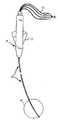
図1は、一実施例では、電気生理学、RF切除又は類似の用途のカテーテル10である本発明の斜視図であり、該カテーテルは、細長い可撓性の略円柱中空ボディ12と、ボディ12の基端部15に連結された作動ハンドル14と、を備える。次の説明から理解されるように、カテーテル10は、従来技術の作動ハンドルと比較して、作動ハンドル14がボディ12の末端部16の操舵移動を有意に増加させるように構成されているという点で有利である。本願明細書を通して、カテーテルという用語は、カテーテル、シース及び類似の医療装置を、限定すること無く、含むことが意図されている。 FIG. 1 is a perspective view of the present invention, which, in one embodiment, is a
一実施例では、ボディ12は、典型的には、ポリウレタン、ナイロン、又は、任意の適切な非導電性材料でできている。ボディ12は、カテーテル10の血液接触区分の一部分として機能する。 In one embodiment, the
図1に示されるように、ボディ12の末端部16は、複数の間隔を隔てた電極18を備えている。各々の電極18は、ボディ12及びハンドル14を通って電気プラグ24に接続するため延在する細い電気伝導ワイヤ22に接続されている。各々の電気プラグ24は、ハンドル14の基端部から延在し、記録、監視又はRF切除の装置内に挿入されるように適合されている。 As shown in FIG. 1, the
図1から理解することができるように、ボディ12の末端部16は、ハンドル14に移動可能に取り付けられたアクチュエータ30を選択的に移動することにより操作される。一実施例では、アクチュエータ30は、略平坦即ちフラットであり、ハンドル14の後部近傍により幅広い部分を備えた略デルタ形状を有している。一実施例では、アクチュエータ30は、カテーテルの操作者の親指と人差し指との間に快適に適合するのに十分なほど幅広い。 As can be seen from FIG. 1, the
図1に示されるように、一実施例では、アクチュエータ30は、ハンドル14の上側部分14aと下側部分14bとの間に受け入れられ又は挟まれている。しかし、本発明の範囲及び意図から逸脱すること無く、デルタ形状のアクチュエータ30に対する代替として他のアクチュエータ形態を使用することができることが理解されよう。 As shown in FIG. 1, in one embodiment, the
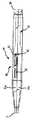
ボディ12の形態の詳細な説明のために、図2、3a、3b及び3cを参照する。図2は、ボディ12の補強を明らかにするためボディ12の外側表面が取り除かれた状態で示されたカテーテル10の斜視図である。図3aは、図2の円Aにより囲まれたボディ12の末端部16の拡大された縦断面図である。図3bは、図3aのラインA−Aに沿って取られたボディ12の縦断面図である。図3cは、図3aのラインB−Bに沿って取られたボディ12の縦断面図である。 For a detailed description of the form of the
図2から理解することができるように、一実施例では、ボディ12の外側表面が、ボディ12の補強手段として役立つ内側案内管32を取り囲んでいる。図2から理解することができるように、及び、図3aで領域Xにより詳細に示されているように、内側案内管32は、ハンドル14との内側案内管の接続位置から管32の末端部16の近傍の位置まで固く巻かれたスプリングとして形成されている。領域Yにより図3aに詳細に示されるように、内側案内管32のマッピング端部16の巻き線33は、より容易に曲げ可能な構造を提供するため開放状態で巻かれている。 As can be seen from FIG. 2, in one embodiment, the outer surface of the
図3a乃至図3cに示されるように、一対の可撓性動作ワイヤ34、36は、内側案内管32の内部に並んだ関係で配置されている。一実施例では、動作ワイヤ34、36は、超弾性のニチノールでできたフラットワイヤから形成されている。一実施例では、動作ワイヤ34、36は、引っ張りワイヤ又は張力ワイヤとして機能するように適合されている。別の実施例では、動作ワイヤ34、36は、押し/引きワイヤ、又は、張力/圧縮ワイヤとして機能するように構成されている。 As shown in FIGS. 3 a to 3 c, the pair of
図3a及び図3bに示されるように、一実施例では、作動ワイヤ34、36は、動作ワイヤ34、36は、管の末端部の近傍の位置からハンドル14に向かって内側案内管32の長さに沿って延在する略円形断面を有する。図3a及び図3bに示されるように、一実施例では、各々の動作ワイヤ34、36の末端部34a、36aは、略平坦化されたリボン状断面を更に有する。 As shown in FIGS. 3a and 3b, in one embodiment, the
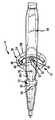
本発明のカテーテル動作ハンドル14の詳細な説明のために、図4乃至図6を参照する。図4は、一実施例に係るハンドル14の後面斜視図である。図5は、図4に表されたハンドル14の平面図である。図6は、図4に表されたハンドル14の側面図である。 For a detailed description of the
図4に示されたように、ハンドル14は、略円柱であり、末端部37及び基端部38を備える。末端部37は、ボディ12の基端部15に連結するように構成されている(図1参照)。基端部38は、開口部40を有する。ワイヤ22は、該開口部40を通って、電極18から電気プラグ24へのそれらの途上に配置されてもよい(図1参照)。 As shown in FIG. 4, the
図4及び図6に示されるように、一実施例では、ハンドル14は、上側部分14a及び下側部分14bの間に形成されたスロット42を内部に有する。スロット42は、アクチュエータ30がハンドル14を通って並列に枢動式に変位することを可能にする。 As shown in FIGS. 4 and 6, in one embodiment, the
図5及び図6に示されるように、空洞部44(一点鎖線により示される)は、基端部38の開口部40から末端部37の開口部まで延在する。空洞部44は、経路を提供し、該経路を通って、ワイヤ22はハンドル14を通過することができる。ボディ12がその長さに沿って延在する管腔を備える一実施例では、空洞部44は、経路として機能し、該経路を通ってカテーテル又は他の細長い医療装置を、ハンドル14を通ってボディ12の管腔内に通過させることができる。図5に示されるように、動作ワイヤ34、36は、ボディ12からハンドル14の空洞部44内へと延在し、ハンドル14の動作機構46の要素へと連結する。 As shown in FIGS. 5 and 6, the cavity 44 (indicated by the alternate long and short dash line) extends from the
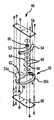
ハンドル14の動作機構46の一実施例の詳細な説明のために、図7乃至図9を参照する。図7は、ハンドル14の動作機構46の分解斜視図である。図8は、ハンドル14の組み立てられた動作機構46の斜視図である。図9は、ハンドル14の組み立てられた動作機構の側面図である。 For a detailed description of one embodiment of the
図7に示されるように、一実施例では、動作機構46は、1つ以上のプーリー(即ち、プーリーアッセンブリ)48と、軸部52に取り付けられたピニオンギア50と、アクチュエータ30に取り付けられた内部弧状ギアラック54と、枢動部56と、上側及び下側フレームプレート58、60と、を備える。図5、8及び9に示されるように、1つ以上のプーリー48は、軸部2及びピニオンギア50と同軸である構成でピニオンギア50の軸部52に動かないように取り付けられている。軸部52は、上側及び下側フレームプレート58、60の間に延在し、該プレートに枢動式に連結されている。従って、軸部52、ピニオンギア50、及び、1つ以上のプーリー48は、上側及び下側フレームプレート58、60に対して、一体ユニットとして軸部52の軸線の回りに枢動することができる。 As shown in FIG. 7, in one embodiment, the
図5、8及び9に示されるように、一実施例でデルタ形状に形成されたアクチュエータ30は、その頂部30aの近傍の枢動孔62を介して枢動部56に枢動式に取り付けられており、該枢動部は、上側及び下側フレームプレート58及び60の間に延在している。ギアラック54は、アクチュエータ30に取り付けられ、ギアラック54は、アクチュエータ30のベース端部30bの近傍でアクチュエータ30を横方向に横切って延在するようにアクチュエータ30に取り付けられている。 As shown in FIGS. 5, 8 and 9, the
図7及び図9に示されるように、1つ以上のプーリー48は、1つ以上のプーリー(即ち、プーリーアッセンブリ)48の周辺部の回りに延在する一対の平行チャンネル64,66を提供する。単一プーリー48が備え付けられた一実施例では、単一プーリー48は、一対の平行チャンネル64、66を有する。一対のプーリー48が備え付けられた一実施例では、各々のプーリー48は、他方のプーリー48の単一チャンネル66に平行である単一チャンネル64を有する。 As shown in FIGS. 7 and 9, the one or
図5及び図9に示されるように、各々の動作ワイヤ34、36は、その各々のチャンネル64、66内に収容される。各々の動作ワイヤ34、36は、ワイヤ34、36の基端部が通過してその対応するプーリー48内に至るような孔68等の取り付け特徴を介して、その各々のチャンネル64、66内に付けられる。 As shown in FIGS. 5 and 9, each working
図9に示されるように、チャンネル64、66は、互いに平行であり、その結果、動作ワイヤ34、36がそれらの各々のチャンネル64、66からボディ12に向かって延在するとき、動作ワイヤ34、36は、互いから垂直方向にオフセットされている。一実施例では、図5に示されるように、案内ブロック70(一点鎖線により示される)はハンドル14の空洞部44内に設けられており、それにより動作ワイヤ34、36をボディ12を通して移動させるとき該動作ワイヤ34、36が並列して同一平面にある関係へと動作ワイヤ34、36を整列させる。動作ワイヤ34、36は、それらの各々のチャンネル64、66から出て、それらワイヤが案内ブロック70内の孔を通過するとき適切に整列され、ボディの末端部16に至るそれらの途上でボディ12の基端部15に入る。案内ブロック70は、動作機構46内の拘束を防止するため各動作ワイヤ34、36をその各々のチャンネル64、66と適切に整列させるように機能する。 As shown in FIG. 9, the
一実施例では、案内ブロック70は、1つ以上のフレームプレート58、60に付着される。一実施例では、案内ブロック70は、1つ以上のハンドル部分14a、14bに付着される。 In one embodiment, guide
一実施例では、代替のアクチュエータ/案内構成の平面図である図10に示されるように、図5に示される案内ブロック70が、2つの可動案内部72、74で代用されている。図10に示されるように、可動案内部72、74の基端部は、リンク76、78を介して枢動部56の両側に連結されている。可動案内部72、74は、ハンドル14の空洞部44内に摺動可能に収容されている。かくして、アクチュエータ30が第1の方向に枢動部56の回りに枢動されるとき、第1の可動案内部72は、その各々のリンク76により末端方向に押しやられ、第2の可動案内部74は、その各々のリンク78により基端方向に押しやられる。これとは逆に、アクチュエータ30を、第1の方向とは反対の第2の方向に枢動させることにより、可動案内部72、74を逆方向に枢動させることができる。その結果、可動案内部74、76は、後述されるように、それらの各々の作動ワイヤ34、46の末端方向の変位及び基端方向の変位をおおよそ模擬することができる。 In one embodiment, two
図5に示されるように、ピニオンギア50は、ギアラック54と噛み合っている。かくして、ユーザーがアクチュエータ30を第1の方向に枢動部56の回りに枢動させるためアクチュエータ30に力を加えたとき、ギアラック54の歯は、ピニオンギア50の歯と噛み合い、ピニオンギア50及び1つ以上のプーリー48を軸部52の軸の回りに枢動させる。動作ワイヤ34、36は、プーリー48の両側でそれらの各々のチャンネル64、66内に入っている。その結果、プーリー48が枢動するとき、動作ワイヤ34、36の一方は、引っ張り込まれ(即ち、プーリー48の回りに巻かれる)、動作ワイヤ34、36の他方は、押し戻される(即ち、プーリー48の回りから巻き解かれる)。逆に、アクチュエータ30が第1の方向とは反対の第2の方向に駆動される場合、プーリー48及び動作ワイヤ34、36の運動は逆転する。 As shown in FIG. 5, the
動作ワイヤ34、36が引っ張りワイヤ即ち張力ワイヤである一実施例では、引っ張り込まれた動作ワイヤ34、36は、張力がかけられた状態に置かれ、押し戻された動作ワイヤ34、36は、ハンドル14内で偏向する(即ち、ワイヤ34、36が無負荷状態に置かれ、圧縮負荷を伝達しない)。作動ワイヤ34、36が引き/押し又は張力/圧縮ワイヤである一実施例では、引っ張り込まれた動作ワイヤ34、36は、張力がかけられた状態に置かれ、押し戻された動作ワイヤ34、36は、外方に押している(即ち、ワイヤ34、36が圧縮負荷を伝達する)。 In one embodiment in which the
一実施例では、チャンネル64、66に取り付けられた動作ワイヤ34、36の端部の間隔は、プーリー車輪48の直径に等しくなるように前もって成形されているのが好ましい。これは有利な構成となる。当該構成は、前もって成形された動作ワイヤ34、36が張力スプリングとして機能することを可能にし、カテーテル10を操舵するため要求される力の量を減少させるからである。 In one embodiment, the distance between the ends of the operating
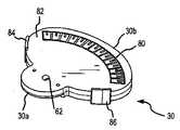
一実施例では、アクチュエータ30の頂面斜視図である図11に示されるように、位置インジケータ80が、アクチュエータベース端部30bの近傍でアクチュエータ30の頂部表面82を横断して略弧状に延在する。位置インジケータ80は、アクチュエータ30が開始位置から変位された範囲をユーザーが追跡又は測定することを援助する。一実施例では、位置インジケータ80は、ハンドル14の頂部14aから延在する要素により係合することができるアクチュエータ30の頂部表面82の3次元浮彫り細工である。そのような係合は、ユーザーによる意識的努力無しにアクチュエータ30を変位された位置に積極的に維持させる。 In one embodiment, as shown in FIG. 11, which is a top perspective view of the
図11に示されるように、一実施例では、指配置パッド84、86が、ユーザーの指との係合を容易にするためアクチュエータ30の横方向側面に設けられ、アクチュエータ30の操作を援助している。一実施例では、パッド84、86は、ハンドル14の両側に当接する停止部として機能し、アクチュエータ30がハンドル14を通って過度に延在することを防止する。 As shown in FIG. 11, in one embodiment,
図5に示されるように、一実施例では、プーリー48は、アクチュエータ30の反対方向における略等しい移動(及びこれによりプーリー48の回転)を提供するように、ハンドル14内に横方向の略中央に配置されている。これは、勿論、一方の方向対他方の方向において移動又は動作を増大させる特定の必要性がある場合には、変えることができる。 As shown in FIG. 5, in one embodiment, the
一実施例では、ピニオン50は、ラック54上の歯、若しくは、はめ歯と噛み合う、歯、若しくは、はめ歯を備える。別の実施例では、ピニオン50は、歯を備えていない。その代わりに、ピニオン50は、ラック54上に提供された滑らかな表面に沿って載り、ピニオン50及びラック54の周辺部の間で生じた摩擦力がプーリー48のための回転力を提供してもよい。代替例として、プーリー48は、歯を備えた又は歯を備えていないラック54と直接係合してもよい。ハンドル14に対するアクチュエータ30の移動は、ピニオン50がラック54と噛み合うときプーリー48の運動(即ち回転)を生じさせる。プーリー48の回転は、従来技術のアクチュエータにより提供される移動の長さと比べて、事実上増大した長さの移動を通して、動作ワイヤ34、36の直線運動を生じさせる。 In one embodiment, the
図9に示されるように、一実施例では、動作ワイヤ34、36は、2つの別個のチャンネル64、66内に配置された2つの別個のワイヤとして表されている。しかし、別の実施例では、動作ワイヤ34、36は、1つ以上のチャンネル内に収容される1つの動作ワイヤを形成するため互いに接続されていてもよい。 As shown in FIG. 9, in one embodiment, the operating
図5に示されるように、一実施例では、ギアラック54は、弧状内側ギア(即ち、ギアラック54の歯88がギアラック54の内側円周エッジにある)であり、ピニオンギア50は、ピニオンギア50の歯90がギアラック54の歯88と噛み合うように、ギアラック54と枢動部56との間に配置されている。しかし、他の実施例では、ギアラック54及びピニオンギア50は、他の構成を持っている。例えば、ハンドル14内に取り付けられた動作機構46の平面図である図12に示されるように、一実施例では、ギアラック54は、弧状外側ギア(即ち、ギアラック54の歯88がギアラック54の外側円周エッジにある)であり、ギアラック54は、ピニオンギア50の歯90がギアラック54の歯88と噛み合うように、ピニオンギア50と枢動部56との間に配置されている。他の実施例では、ギアラック54は、直線状即ちストレート(即ち、非弧状)であり、ピニオンギア50は、ギアラック54のいずれの側にも配置されていてもよい。 As shown in FIG. 5, in one embodiment, the
一実施例では、ギアラック54は、5.555cm(2.187インチ)のピッチ直径を持ち、ピニオンギア50は、0.714cm(0.281インチ)のピッチ直径を持ち、プーリー64、66の直径は、1.27cm(0.500インチ)である。他の実施例では、ギアラック54のピッチ直径は、約2.54cm(約1.00インチ)及び約12.7cm(約5.00インチ)の間にあり、ピニオンギア50のためのピッチ直径は、約0.3175cm(約0.125インチ)及び約2.54cm(約1.00インチ)の間にあり、プーリーのチャンネル64、66の直径は、約0.3175cm(約0.125インチ)及び約5.08cm(約2.00インチ)の間にある。図11に示されるように、一実施例では、ギアラック54は、枢動部64と、ギアラック54のピッチ直径により形成された半円との間の半径Rが、ギアラック54のピッチ直径の半分であるように枢動部62に対して配置されている。 In one embodiment, the
機構46がプーリーの代わりに対向する直線ギアラックを駆動する動作機構46の別の実施例を説明するために、図13及び図14を参照する。図13は、動作機構46の分解斜視図であり、図14は、ハンドル14内に取り付けられた、組み立てられた動作機構の平面図である。 To describe another embodiment of the
図13及び図14に示されるように、動作機構46は、軸部52に取り付けられた上側ピニオンギア50と、アクチュエータ30に取り付けられた内側弧状ギアラック54と、枢動部56と、下側ピニオンギア100と、一対の直線ギアラック102、104と、上側及び下側フレームプレート58、60とを備える。図13及び図14から理解することができるように、下側ピニオンギア100は、軸部52及び上側ピニオンギア50と同軸となる構成で、上側ピニオンギア50の軸部52に動かないように取り付けられている。軸部52は、上側フレームプレート58及び下側フレームプレート60の間に延在し、これらのプレートに枢動式に取り付けられている。従って、軸部52、上側ピニオンギア50及び下側ピニオンギア100は、上側フレームプレート58及び下側フレームプレート60に対して一体のユニットとして軸部52の軸線の回りに枢動することができる。 As shown in FIGS. 13 and 14, the
図13及び図14から理解することができるように、下側ピニオンギア100は、上側フレームプレート58に形成されたラックスロット106内に摺動可能に配置された、直線ギアラック102、104の間に配置される。直線ギアラック102、104は、それらの歯の側108が互いに対面し、下側ピニオンギア100の歯と係合するように配置されている。下側フレームプレート60は、上側フレームプレート58の底表面に当接し、それらの各々のラックスロット106内で直線ギアラック102、104を覆っている。
直線ギアラック102、104の各々の末端部は、動作ワイヤ34、36の基端部に連結されている。As can be understood from FIGS. 13 and 14, the
The distal end of each of the linear gear racks 102, 104 is connected to the proximal end of the operating
図13に示されるように、一実施例では、直線ギアラック102、104は、互いに略平行に配置されている。別の実施例では、図14に表されるように、直線ギアラック102、104は、直線ギアラック102、104の各々が直ぐ隣接するハンドル側壁110に略平行となるように、非平行の構成で配置されている。いずれの実施例においても、直線ギアラック102、104は、それらの各々のラックスロット106内に摺動可能に変位することができる。 As shown in FIG. 13, in one embodiment, the linear gear racks 102, 104 are arranged substantially parallel to each other. In another embodiment, as represented in FIG. 14, the linear gear racks 102, 104 are arranged in a non-parallel configuration such that each of the linear gear racks 102, 104 is substantially parallel to the immediately
図13及び図14に示されるように、一実施例でデルタ形状に形成されるアクチュエータ30は、その頂部30aの近傍の枢動孔62を介して枢動部56に枢動式に取り付けられている。該枢動部は、少なくとも上側フレームプレート58内に延在する。ギアラック54は、該ギアラック54がアクチュエータ30のベース端部30bの近傍でアクチュエータ30を横方向に横切って延在するようにアクチュエータ30に取り付けられている。 As shown in FIGS. 13 and 14, the
図14に示されるように、上側ピニオンギア50は、弧状内側ギアラック54と噛み合い、下側ピニオンギア100は直線ギアラック102、104と噛み合っている。かくして、ユーザーがアクチュエータ30に力を加えてアクチュエータ30を枢動部56の回りに第1の方向に枢動させるとき、ギアラック54の歯は上側ピニオンギア50の歯と噛み合い、上側ピニオンギア50及び下側ピニオンギア100を軸部52の軸線の回りに枢動させる。下側ピニオンギア100の歯は、直線ギアラック102、104の歯表面108と噛み合い、直線ギアラック102の一つを基端方向に駆動させ、他方のギアラック104を末端方向に駆動させる。逆に、アクチュエータ30が第1の方向とは反対の第2の方向に駆動される場合には、下側ピニオンギア100は、直線ギアラック102、104の移動方向を逆転させる。 As shown in FIG. 14, the
図13及び図14に示されるように、動作ワイヤ34、36の各々が直線ギアラック104の末端部に取り付けられているので、ワイヤ34、36の各々は、その各々の直線ギアラック104と共に変位する。例えば、動作ワイヤ34、36が引っ張りワイヤ即ち張力ワイヤである場合、直線ギアラック102、104を基端方向に変位させることにより基端方向に引っ張られるワイヤ34、36は、張力がかけられた状態に置かれており、直線ギアラック102、104を末端方向に変位させることにより末端方向に押される動作ワイヤ34、36はハンドル14内部で偏向される(即ち、ワイヤ34、36は、無負荷状態に置かれ、圧縮負荷を伝達しない)。一実施例では、動作ワイヤ34、36が引き/押しワイヤ又は張力/圧縮ワイヤである場合、直線ギアラック102、104を基端方向に変位させることにより基端方向に引っ張られるワイヤ34、36は、張力がかけられた状態に置かれており、直線ギアラック102、104を末端方向に変位させることにより末端方向に押される動作ワイヤ34、36は外側に押されている(即ち、ワイヤ34、36は、圧縮負荷を伝達する)。 As shown in FIGS. 13 and 14, each of the operating
本発明が好ましい実施例を参照して説明されたが、当業者は、本発明の精神及び範囲から逸脱すること無く、その形態及び詳細において様々な変更をなし得ることを理解するであろう。 Although the present invention has been described with reference to preferred embodiments, workers skilled in the art will recognize that various changes can be made in form and detail without departing from the spirit and scope of the invention.
Claims (15)
Translated fromJapaneseハンドル(14)に可動式に取り付けられたアクチュエータ(30)と、
前記第1の動作ワイヤを受け入れるための第1のチャンネル(64)と、前記第2の動作ワイヤを受け入れるための第2のチャンネル(66)とを備える、プーリーアッセンブリ(48)と、
前記プーリーアッセンブリの係合部(50)と係合される、ギアラック(54)と、
を備え、
前記アクチュエータが前記ハンドルに対して変位されたとき、前記ラックと前記プーリーアッセンブリとの間の係合は、該プーリーアッセンブリを前記ハンドルに対して枢動させるようになされた、動作アッセンブリにおいて、
前記アクチュエータ(30)は、頂部(30a)とベース端部(30b)とを有する略デルタ形状であり、前記アクチュエータは、前記アクチュエータの頂部の近傍で前記ハンドルに枢動式に連結され、
前記プーリーアッセンブリ(48)は、軸部(52)により前記ハンドルに枢動式に取付けられ、前記プーリーアッセンブリは、前記軸部に動かないように取り付けられている1つ以上のプーリー(48)を含み、
前記プーリーアッセンブリの前記係合部(50)は、前記軸部に取り付けられたピニオンギア(50)であり、前記ピニオンギアは、前記ギアラック(54)と係合し、
前記ギアラックは、弧状ギアラックであり、前記ギアラックは、前記弧状ギアラックが前記アクチュエータのベース端部の近傍で前記アクチュエータを横方向に横切って実質的に延在するように、前記アクチュエータに固定される、
ことを特徴とする動作アッセンブリ。A working assembly for a catheter(10) comprising first and second working wires(34, 36) comprising:
An actuator(30) movably attached to the handle(14) ;
A first channel(64) for receiving the first operation wire, and a second channel for receiving the second operation wire(66), andflop over Lee assembly(48),
Engaged engagement portion(50) of thepre-Symbol pulley assembly, agear rack (54),
With
When the actuator is displaced relative to the handle, the engagement between the rack and the pulley assembly is inan operating assembly adapted to pivot the pulley assembly relative to the handle;
The actuator (30) is generally delta-shaped having a top (30a) and a base end (30b), the actuator pivotally connected to the handle near the top of the actuator;
The pulley assembly (48) is pivotally attached to the handle by a shaft (52), and the pulley assembly includes one or more pulleys (48) that are fixedly attached to the shaft. Including
The engaging portion (50) of the pulley assembly is a pinion gear (50) attached to the shaft portion, and the pinion gear engages with the gear rack (54),
The gear rack is an arcuate gear rack, and the gear rack is secured to the actuator such that the arcuate gear rack extends substantially transversely across the actuator in the vicinity of the actuator base end.
An operation assemblycharacterized by that .
基端部及び末端部(15,16)を備える、細長い可撓性の中空ボディ(12)と、
前記ボディの基端部に取り付けられたハンドル(14)とを備え、
前記第1及び第2の可撓性動作ワイヤ(34,36)は前記ボディ内で並列の関係で配置され、前記ボディの基端部から延在し、該動作ワイヤは、前記ボディの末端部を偏向させるように構成される、
請求項14に記載のカテーテル。A catheter(10) ,
An elongated flexible hollow body(12) comprising a proximal end and a distal end(15, 16) ;
A handle (14) attached to the proximal end of the body;
Said first and second flexible operation wires (34, 36) are arranged in parallel relation within said body,and extends from the proximal end of said body, said operating wire distal end of said body Configured to deflect,
The catheter accordingto claim 14 .
Applications Claiming Priority (1)
| Application Number | Priority Date | Filing Date | Title |
|---|---|---|---|
| US11/024,181US8583260B2 (en) | 2004-12-28 | 2004-12-28 | Long travel steerable catheter actuator |
Publications (2)
| Publication Number | Publication Date |
|---|---|
| JP2006187614A JP2006187614A (en) | 2006-07-20 |
| JP4354949B2true JP4354949B2 (en) | 2009-10-28 |
Family
ID=35897555
Family Applications (1)
| Application Number | Title | Priority Date | Filing Date |
|---|---|---|---|
| JP2005378452AActiveJP4354949B2 (en) | 2004-12-28 | 2005-12-28 | Long-distance steerable catheter actuator |
Country Status (6)
| Country | Link |
|---|---|
| US (2) | US8583260B2 (en) |
| EP (1) | EP1676596B1 (en) |
| JP (1) | JP4354949B2 (en) |
| AT (1) | ATE429264T1 (en) |
| CA (1) | CA2531415C (en) |
| DE (1) | DE602005014074D1 (en) |
Families Citing this family (52)
| Publication number | Priority date | Publication date | Assignee | Title |
|---|---|---|---|---|
| DE102004003166B4 (en)* | 2004-01-21 | 2011-09-15 | Siemens Ag | catheter |
| US7591784B2 (en)* | 2005-04-26 | 2009-09-22 | St. Jude Medical, Atrial Fibrillation Division, Inc. | Bi-directional handle for a catheter |
| US8777929B2 (en) | 2005-06-28 | 2014-07-15 | St. Jude Medical, Atrial Fibrillation Division, Inc. | Auto lock for catheter handle |
| US7465288B2 (en)* | 2005-06-28 | 2008-12-16 | St. Jude Medical, Atrial Fibrillation Division, Inc. | Actuation handle for a catheter |
| US9833595B2 (en) | 2005-12-30 | 2017-12-05 | Biosense Webster, Inc. | Dual-lever bi-directional handle |
| US7931616B2 (en)* | 2006-10-31 | 2011-04-26 | Biosense Webster, Inc. | Insert molded catheter puller member connectors and method of making |
| JP5575777B2 (en) | 2008-09-30 | 2014-08-20 | ディファイン, インコーポレイテッド | System used to treat vertebral fractures |
| US8808345B2 (en) | 2008-12-31 | 2014-08-19 | Medtronic Ardian Luxembourg S.A.R.L. | Handle assemblies for intravascular treatment devices and associated systems and methods |
| US8676290B2 (en)* | 2010-05-11 | 2014-03-18 | St. Jude Medical, Atrial Fibrillation Division, Inc. | Multi-directional catheter control handle |
| US8556850B2 (en) | 2008-12-31 | 2013-10-15 | St. Jude Medical, Atrial Fibrillation Division, Inc. | Shaft and handle for a catheter with independently-deflectable segments |
| US20100298832A1 (en) | 2009-05-20 | 2010-11-25 | Osseon Therapeutics, Inc. | Steerable curvable vertebroplasty drill |
| US8734426B2 (en)* | 2009-10-22 | 2014-05-27 | Cook Medical Technologies Llc | Locking assembly for a drainage catheter |
| WO2011066113A1 (en)* | 2009-11-24 | 2011-06-03 | Vance Products Incorporated, D/B/A Cook Urological Incorporated | Locking assembly for a drainage catheter |
| US10232150B2 (en)* | 2010-03-11 | 2019-03-19 | Merit Medical Systems, Inc. | Body cavity drainage devices and related methods |
| US8369923B2 (en)* | 2010-04-14 | 2013-02-05 | St. Jude Medical, Atrial Fibrillation Division, Inc. | Dual-deflecting electrophysiology catheter |
| US9526507B2 (en) | 2010-04-29 | 2016-12-27 | Dfine, Inc. | System for use in treatment of vertebral fractures |
| CN102985015B (en)* | 2010-04-29 | 2016-08-03 | Dfine有限公司 | System for treating vertebral fractures |
| US9125671B2 (en) | 2010-04-29 | 2015-09-08 | Dfine, Inc. | System for use in treatment of vertebral fractures |
| US9289147B2 (en) | 2010-05-11 | 2016-03-22 | St. Jude Medical, Atrial Fibrillation Division, Inc. | Multi-directional flexible wire harness for medical devices |
| USD726905S1 (en) | 2011-05-11 | 2015-04-14 | St. Jude Medical, Atrial Fibrillation Division, Inc. | Control handle for a medical device |
| US9351790B2 (en) | 2011-09-17 | 2016-05-31 | M.O.E. Medical Devices Llc | Electrode geometries and method for applying electric field treatment to parts of the body |
| US9757538B2 (en) | 2011-12-15 | 2017-09-12 | Imricor Medical Systems, Inc. | MRI compatible control handle for steerable sheath with audible, tactile and/or visual means |
| US20140135745A1 (en) | 2011-12-15 | 2014-05-15 | Imricor Medical Systems, Inc. | Mri compatible handle and steerable sheath |
| US9821143B2 (en) | 2011-12-15 | 2017-11-21 | Imricor Medical Systems, Inc. | Steerable sheath including elastomeric member |
| JP6317927B2 (en) | 2012-01-09 | 2018-04-25 | ムー・メディカル・デバイスズ・エルエルシーMoe Medical Devices Llc | Plasma assisted skin treatment |
| TW201509450A (en)* | 2013-09-11 | 2015-03-16 | Lin Que Hong | Intubation aid |
| WO2014049825A1 (en) | 2012-09-28 | 2014-04-03 | テルモ株式会社 | Operation member and medical instrument |
| USD718436S1 (en)* | 2012-10-26 | 2014-11-25 | Beyondevices Lda | Apparatus and equipment for delivering medication to a patient |
| PT106603A (en)* | 2012-10-26 | 2014-04-28 | Beyondevices Lda | DISTRIBUTION MECHANISM FOR THE ADMINISTRATION OF PHARMACEUTICAL FORMS IN CORPORATE FORMS AND APPLICATOR UNDERSTANDING THE SAME |
| JP5686386B2 (en)* | 2013-01-20 | 2015-03-18 | 株式会社リバーセイコー | Catheter bending operation device |
| JP6192951B2 (en)* | 2013-03-01 | 2017-09-06 | テルモ株式会社 | Actuating member and medical device |
| US9375550B2 (en) | 2013-03-15 | 2016-06-28 | St. Jude Medical, Atrial Fibrillation Division, Inc. | Catheter actuators providing mechanical advantage |
| US9649415B2 (en) | 2014-06-27 | 2017-05-16 | Harrison M. Lazarus | Surgical kits for body cavity drainage and related methods |
| US9821097B2 (en) | 2014-06-27 | 2017-11-21 | Merit Medical Systems, Inc. | Body cavity drainage devices including drainage tubes having inline portions and related methods |
| US9604033B2 (en) | 2014-06-27 | 2017-03-28 | Harrison M. Lazarus | Body cavity drainage devices with locking devices and related methods |
| US10029036B2 (en) | 2014-06-27 | 2018-07-24 | Merit Medical Systems, Inc. | Placement tools for body cavity drainage devices and related methods |
| EP3256199A4 (en)* | 2015-02-13 | 2018-11-07 | Cathrx Ltd | Improved catheter handle |
| JP7074666B2 (en) | 2015-11-25 | 2022-05-24 | メリット・メディカル・システムズ・インコーポレイテッド | Maneuverable sheath catheter and how to use |
| US10675443B2 (en) | 2016-03-07 | 2020-06-09 | St. Jude Medical, Cardiology Division, Inc. | Medical device including an actuator restraining assembly |
| JP2019534130A (en) | 2016-10-27 | 2019-11-28 | ディーファイン,インコーポレイティド | Articulated osteotome with cement delivery channel |
| WO2018097992A2 (en) | 2016-11-22 | 2018-05-31 | Dfine, Inc. | Swivel hub |
| CA3041114A1 (en) | 2016-11-28 | 2018-05-31 | Dfine, Inc. | Tumor ablation devices and related methods |
| US10470781B2 (en) | 2016-12-09 | 2019-11-12 | Dfine, Inc. | Medical devices for treating hard tissues and related methods |
| US10660656B2 (en) | 2017-01-06 | 2020-05-26 | Dfine, Inc. | Osteotome with a distal portion for simultaneous advancement and articulation |
| WO2019026995A1 (en)* | 2017-08-02 | 2019-02-07 | 住友ベークライト株式会社 | Medical device |
| US11559662B2 (en) | 2018-04-13 | 2023-01-24 | Merit Medical Systems, Inc. | Steerable drainage devices |
| US11937864B2 (en) | 2018-11-08 | 2024-03-26 | Dfine, Inc. | Ablation systems with parameter-based modulation and related devices and methods |
| US11896330B2 (en)* | 2019-08-15 | 2024-02-13 | Auris Health, Inc. | Robotic medical system having multiple medical instruments |
| CN110507407B (en)* | 2019-09-05 | 2021-02-02 | 孙岩军 | Plasma surgical knife head and plasma surgical device |
| US11986229B2 (en) | 2019-09-18 | 2024-05-21 | Merit Medical Systems, Inc. | Osteotome with inflatable portion and multiwire articulation |
| JP2023529459A (en)* | 2020-06-11 | 2023-07-10 | ボストン サイエンティフィック リミテッド | MEDICAL SYSTEMS, DEVICES AND RELATED METHODS |
| US11654262B2 (en) | 2020-08-26 | 2023-05-23 | Freudenberg Medical, Llc | Handle assembly for controlling a steerable catheter |
Family Cites Families (99)
| Publication number | Priority date | Publication date | Assignee | Title |
|---|---|---|---|---|
| JPS5412846B1 (en) | 1967-10-02 | 1979-05-25 | ||
| US5125895A (en) | 1986-07-22 | 1992-06-30 | Medtronic Versaflex, Inc. | Steerable catheter |
| US4960134A (en) | 1988-11-18 | 1990-10-02 | Webster Wilton W Jr | Steerable catheter |
| US4947827A (en)* | 1988-12-30 | 1990-08-14 | Opielab, Inc. | Flexible endoscope |
| JPH0337033A (en)* | 1989-07-05 | 1991-02-18 | Machida Seisakusho:Kk | Bending action device for endoscope |
| US5891088A (en)* | 1990-02-02 | 1999-04-06 | Ep Technologies, Inc. | Catheter steering assembly providing asymmetric left and right curve configurations |
| US5195968A (en)* | 1990-02-02 | 1993-03-23 | Ingemar Lundquist | Catheter steering mechanism |
| EP0476807A1 (en) | 1990-09-17 | 1992-03-25 | C.R. Bard, Inc. | Core wire steerable catheters |
| US5125896A (en) | 1990-10-10 | 1992-06-30 | C. R. Bard, Inc. | Steerable electrode catheter |
| US5383923A (en) | 1990-10-20 | 1995-01-24 | Webster Laboratories, Inc. | Steerable catheter having puller wire with shape memory |
| US5409453A (en)* | 1992-08-12 | 1995-04-25 | Vidamed, Inc. | Steerable medical probe with stylets |
| US5327889A (en) | 1992-12-01 | 1994-07-12 | Cardiac Pathways Corporation | Mapping and ablation catheter with individually deployable arms and method |
| US5269757A (en) | 1991-12-02 | 1993-12-14 | C. R. Bard, Inc. | Catheter with integral steerable guidewire having linear to rotary movement |
| US5163942A (en)* | 1991-12-09 | 1992-11-17 | Everest Medical Corporation | Surgical instrument with grasping loop for laparoscopic procedures |
| US5327905A (en) | 1992-02-14 | 1994-07-12 | Boaz Avitall | Biplanar deflectable catheter for arrhythmogenic tissue ablation |
| US5354297A (en) | 1992-02-14 | 1994-10-11 | Boaz Avitall | Biplanar deflectable catheter for arrhythmogenic tissue ablation |
| EP0634907B1 (en) | 1992-04-10 | 1997-01-29 | Cardiorhythm | Intracardiac electrical potential reference catheter |
| US5318525A (en) | 1992-04-10 | 1994-06-07 | Medtronic Cardiorhythm | Steerable electrode catheter |
| WO1993020878A1 (en) | 1992-04-10 | 1993-10-28 | Cardiorhythm | Shapable handle for steerable electrode catheter |
| US5281217A (en) | 1992-04-13 | 1994-01-25 | Ep Technologies, Inc. | Steerable antenna systems for cardiac ablation that minimize tissue damage and blood coagulation due to conductive heating patterns |
| US5667488A (en)* | 1992-08-12 | 1997-09-16 | Vidamed, Inc. | Transurethral needle ablation device and method for the treatment of the prostate |
| US5364351A (en)* | 1992-11-13 | 1994-11-15 | Ep Technologies, Inc. | Catheter steering mechanism |
| CA2109980A1 (en) | 1992-12-01 | 1994-06-02 | Mir A. Imran | Steerable catheter with adjustable bend location and/or radius and method |
| US5391147A (en) | 1992-12-01 | 1995-02-21 | Cardiac Pathways Corporation | Steerable catheter with adjustable bend location and/or radius and method |
| US5389073A (en) | 1992-12-01 | 1995-02-14 | Cardiac Pathways Corporation | Steerable catheter with adjustable bend location |
| US5330466A (en) | 1992-12-01 | 1994-07-19 | Cardiac Pathways Corporation | Control mechanism and system and method for steering distal extremity of a flexible elongate member |
| US5327906A (en)* | 1993-04-28 | 1994-07-12 | Medtronic, Inc. | Steerable stylet handle |
| ES2174875T3 (en) | 1993-04-28 | 2002-11-16 | Biosense Webster Inc | ELECTROPHYSIOLOGICAL CATHETER WITH PRECURVED POINT. |
| US5611777A (en) | 1993-05-14 | 1997-03-18 | C.R. Bard, Inc. | Steerable electrode catheter |
| US5487757A (en) | 1993-07-20 | 1996-01-30 | Medtronic Cardiorhythm | Multicurve deflectable catheter |
| US5545200A (en) | 1993-07-20 | 1996-08-13 | Medtronic Cardiorhythm | Steerable electrophysiology catheter |
| US5562619A (en) | 1993-08-19 | 1996-10-08 | Boston Scientific Corporation | Deflectable catheter |
| US5431168A (en) | 1993-08-23 | 1995-07-11 | Cordis-Webster, Inc. | Steerable open-lumen catheter |
| US5342295A (en) | 1993-09-24 | 1994-08-30 | Cardiac Pathways Corporation | Catheter assembly, catheter and multi-port introducer for use therewith |
| US5582609A (en) | 1993-10-14 | 1996-12-10 | Ep Technologies, Inc. | Systems and methods for forming large lesions in body tissue using curvilinear electrode elements |
| US5575810A (en) | 1993-10-15 | 1996-11-19 | Ep Technologies, Inc. | Composite structures and methods for ablating tissue to form complex lesion patterns in the treatment of cardiac conditions and the like |
| US5402793A (en)* | 1993-11-19 | 1995-04-04 | Advanced Technology Laboratories, Inc. | Ultrasonic transesophageal probe for the imaging and diagnosis of multiple scan planes |
| US5487385A (en) | 1993-12-03 | 1996-01-30 | Avitall; Boaz | Atrial mapping and ablation catheter system |
| US5921924A (en) | 1993-12-03 | 1999-07-13 | Avitall; Boaz | Mapping and ablation catheter system utilizing multiple control elements |
| US5730127A (en) | 1993-12-03 | 1998-03-24 | Avitall; Boaz | Mapping and ablation catheter system |
| WO1995018647A2 (en)* | 1994-01-06 | 1995-07-13 | Scimed Life Systems Inc | Thermoplastic polyimide balloon catheter |
| US5395328A (en) | 1994-01-19 | 1995-03-07 | Daig Corporation | Steerable catheter tip having an X-shaped lumen |
| US5395329A (en)* | 1994-01-19 | 1995-03-07 | Daig Corporation | Control handle for steerable catheter |
| US6071274A (en) | 1996-12-19 | 2000-06-06 | Ep Technologies, Inc. | Loop structures for supporting multiple electrode elements |
| US5885278A (en) | 1994-10-07 | 1999-03-23 | E.P. Technologies, Inc. | Structures for deploying movable electrode elements |
| US5836947A (en) | 1994-10-07 | 1998-11-17 | Ep Technologies, Inc. | Flexible structures having movable splines for supporting electrode elements |
| US5599305A (en) | 1994-10-24 | 1997-02-04 | Cardiovascular Concepts, Inc. | Large-diameter introducer sheath having hemostasis valve and removable steering mechanism |
| WO1996026675A1 (en) | 1995-02-28 | 1996-09-06 | Boston Scientific Corporation | Deflectable catheter for ablating cardiac tissue |
| AU5558096A (en) | 1995-05-01 | 1996-11-21 | Medtronic Cardiorhythm | Dual curve ablation catheter and method |
| US5656030A (en) | 1995-05-22 | 1997-08-12 | Boston Scientific Corporation | Bidirectional steerable catheter with deflectable distal tip |
| US6090104A (en) | 1995-06-07 | 2000-07-18 | Cordis Webster, Inc. | Catheter with a spirally wound flat ribbon electrode |
| JP3782113B2 (en) | 1995-06-12 | 2006-06-07 | コーディス ウェブスター,インコーポレイティド | Catheter with electromagnetic guidance sensor |
| US5827272A (en) | 1995-08-07 | 1998-10-27 | Medtronic Cardiorhythm | Simplified torquing electrode catheter |
| US5807249A (en) | 1996-02-16 | 1998-09-15 | Medtronic, Inc. | Reduced stiffness, bidirectionally deflecting catheter assembly |
| US5755760A (en) | 1996-03-11 | 1998-05-26 | Medtronic, Inc. | Deflectable catheter |
| US5882346A (en) | 1996-07-15 | 1999-03-16 | Cardiac Pathways Corporation | Shapable catheter using exchangeable core and method of use |
| US5826576A (en) | 1996-08-08 | 1998-10-27 | Medtronic, Inc. | Electrophysiology catheter with multifunction wire and method for making |
| US5779669A (en) | 1996-10-28 | 1998-07-14 | C. R. Bard, Inc. | Steerable catheter with fixed curve |
| US6002955A (en) | 1996-11-08 | 1999-12-14 | Medtronic, Inc. | Stabilized electrophysiology catheter and method for use |
| US5910129A (en) | 1996-12-19 | 1999-06-08 | Ep Technologies, Inc. | Catheter distal assembly with pull wires |
| US6203525B1 (en) | 1996-12-19 | 2001-03-20 | Ep Technologies, Inc. | Catheterdistal assembly with pull wires |
| US6048329A (en) | 1996-12-19 | 2000-04-11 | Ep Technologies, Inc. | Catheter distal assembly with pull wires |
| US6071279A (en) | 1996-12-19 | 2000-06-06 | Ep Technologies, Inc. | Branched structures for supporting multiple electrode elements |
| US6146355A (en)* | 1996-12-30 | 2000-11-14 | Myelotec, Inc. | Steerable catheter |
| US5916213A (en) | 1997-02-04 | 1999-06-29 | Medtronic, Inc. | Systems and methods for tissue mapping and ablation |
| US5944690A (en) | 1997-03-17 | 1999-08-31 | C.R. Bard, Inc. | Slidable control mechanism for steerable catheter |
| US5827278A (en) | 1997-05-20 | 1998-10-27 | Cordis Webster, Inc. | Deflectable tip electrode catheter with nylon stiffener and compression coil |
| US5861024A (en)* | 1997-06-20 | 1999-01-19 | Cardiac Assist Devices, Inc | Electrophysiology catheter and remote actuator therefor |
| EP0900547B1 (en) | 1997-09-05 | 2007-05-30 | Biosense Webster, Inc. | Steerable catheter for detecting and revascularizing ischemic myocardial tissue |
| US6027473A (en) | 1997-09-05 | 2000-02-22 | Cordis Webster, Inc. | Handle for steerable DMR catheter |
| US6123699A (en) | 1997-09-05 | 2000-09-26 | Cordis Webster, Inc. | Omni-directional steerable catheter |
| US5897529A (en) | 1997-09-05 | 1999-04-27 | Cordis Webster, Inc. | Steerable deflectable catheter having improved flexibility |
| US6171277B1 (en)* | 1997-12-01 | 2001-01-09 | Cordis Webster, Inc. | Bi-directional control handle for steerable catheter |
| US6183463B1 (en) | 1997-12-01 | 2001-02-06 | Cordis Webster, Inc. | Bidirectional steerable cathether with bidirectional control handle |
| US6200315B1 (en) | 1997-12-18 | 2001-03-13 | Medtronic, Inc. | Left atrium ablation catheter |
| US6064902A (en) | 1998-04-16 | 2000-05-16 | C.R. Bard, Inc. | Pulmonary vein ablation catheter |
| US6059739A (en) | 1998-05-29 | 2000-05-09 | Medtronic, Inc. | Method and apparatus for deflecting a catheter or lead |
| US6198974B1 (en) | 1998-08-14 | 2001-03-06 | Cordis Webster, Inc. | Bi-directional steerable catheter |
| US6033403A (en) | 1998-10-08 | 2000-03-07 | Irvine Biomedical, Inc. | Long electrode catheter system and methods thereof |
| US6178354B1 (en) | 1998-12-02 | 2001-01-23 | C. R. Bard, Inc. | Internal mechanism for displacing a slidable electrode |
| US6210407B1 (en) | 1998-12-03 | 2001-04-03 | Cordis Webster, Inc. | Bi-directional electrode catheter |
| US6203507B1 (en) | 1999-03-03 | 2001-03-20 | Cordis Webster, Inc. | Deflectable catheter with ergonomic handle |
| US6183435B1 (en) | 1999-03-22 | 2001-02-06 | Cordis Webster, Inc. | Multi-directional steerable catheters and control handles |
| DE19933278C2 (en)* | 1999-07-14 | 2001-11-29 | Biotronik Mess & Therapieg | Controllable catheter |
| US6149663A (en) | 1999-08-17 | 2000-11-21 | Scimed Life Systems, Inc. | Guide wire brake for ablation assembly |
| US6221087B1 (en) | 1999-10-01 | 2001-04-24 | Scimed Life Systems, Inc. | Ablation assembly with safety stop |
| US6440062B1 (en)* | 1999-11-10 | 2002-08-27 | Asahi Kogaku Kogyo Kabushiki Kaisha | Control wire driving mechanism for use in endoscope |
| US6224587B1 (en) | 1999-11-22 | 2001-05-01 | C.R. Bard, Inc. | Steerable catheter |
| US6582536B2 (en)* | 2000-04-24 | 2003-06-24 | Biotran Corporation Inc. | Process for producing steerable sheath catheters |
| US6375654B1 (en) | 2000-05-19 | 2002-04-23 | Cardiofocus, Inc. | Catheter system with working portion radially expandable upon rotation |
| US6571131B1 (en) | 2000-11-10 | 2003-05-27 | Biosense Webster, Inc. | Deflectable catheter with modifiable handle |
| US6652506B2 (en)* | 2001-05-04 | 2003-11-25 | Cardiac Pacemakers, Inc. | Self-locking handle for steering a single or multiple-profile catheter |
| JP3514252B2 (en)* | 2001-11-06 | 2004-03-31 | 昌純 高田 | Self-propelled colonoscope |
| US7025759B2 (en)* | 2002-02-04 | 2006-04-11 | Ebi, L.P. | Steerable catheter |
| US8298161B2 (en)* | 2002-09-12 | 2012-10-30 | Intuitive Surgical Operations, Inc. | Shape-transferring cannula system and method of use |
| US8052636B2 (en)* | 2004-03-05 | 2011-11-08 | Hansen Medical, Inc. | Robotic catheter system and methods |
| US7377906B2 (en)* | 2004-06-15 | 2008-05-27 | Biosense Webster, Inc. | Steering mechanism for bi-directional catheter |
| US7717875B2 (en)* | 2004-07-20 | 2010-05-18 | St. Jude Medical, Atrial Fibrillation Division, Inc. | Steerable catheter with hydraulic or pneumatic actuator |
| US7465288B2 (en)* | 2005-06-28 | 2008-12-16 | St. Jude Medical, Atrial Fibrillation Division, Inc. | Actuation handle for a catheter |
- 2004
- 2004-12-28USUS11/024,181patent/US8583260B2/enactiveActive
- 2005
- 2005-12-22ATAT05028196Tpatent/ATE429264T1/ennot_activeIP Right Cessation
- 2005-12-22DEDE602005014074Tpatent/DE602005014074D1/enactiveActive
- 2005-12-22CACA002531415Apatent/CA2531415C/ennot_activeExpired - Fee Related
- 2005-12-22EPEP05028196Apatent/EP1676596B1/ennot_activeNot-in-force
- 2005-12-28JPJP2005378452Apatent/JP4354949B2/enactiveActive
- 2013
- 2013-10-15USUS14/054,519patent/US10022521B2/enactiveActive
Also Published As
| Publication number | Publication date |
|---|---|
| CA2531415A1 (en) | 2006-06-28 |
| US20140046251A1 (en) | 2014-02-13 |
| JP2006187614A (en) | 2006-07-20 |
| US10022521B2 (en) | 2018-07-17 |
| DE602005014074D1 (en) | 2009-06-04 |
| US20060142695A1 (en) | 2006-06-29 |
| EP1676596B1 (en) | 2009-04-22 |
| US8583260B2 (en) | 2013-11-12 |
| EP1676596A1 (en) | 2006-07-05 |
| ATE429264T1 (en) | 2009-05-15 |
| CA2531415C (en) | 2009-05-12 |
Similar Documents
| Publication | Publication Date | Title |
|---|---|---|
| JP4354949B2 (en) | Long-distance steerable catheter actuator | |
| JP4681050B2 (en) | Actuator handle for catheter | |
| US10737062B2 (en) | Auto lock for catheter handle | |
| JP5944331B2 (en) | Self-locking catheter handle | |
| US5861024A (en) | Electrophysiology catheter and remote actuator therefor | |
| EP1874387B1 (en) | Bi-directional handle for a catheter | |
| US7881809B2 (en) | Electrophysiology/ablation catheter and remote actuator therefor | |
| EP2018203B1 (en) | Auto lock for catheter handle | |
| JP6133049B2 (en) | Self-holding medical device control handle with cam operated clutch mechanism | |
| WO2001085246A1 (en) | Bi-directional steerable catheter with asymmetric fulcrum | |
| JPH07500755A (en) | Catheter with an electrode tip that changes to an asymmetrical shape | |
| EP2386255B1 (en) | Endoscope treatment instrument | |
| US9364636B2 (en) | Steerable intraluminal medical device | |
| CN210204860U (en) | Endoscope operation instrument | |
| KR101703885B1 (en) | Rotation structure of cross way and surgical instrument using it | |
| JPH0582209B2 (en) |
Legal Events
| Date | Code | Title | Description |
|---|---|---|---|
| A131 | Notification of reasons for refusal | Free format text:JAPANESE INTERMEDIATE CODE: A131 Effective date:20090213 | |
| A601 | Written request for extension of time | Free format text:JAPANESE INTERMEDIATE CODE: A601 Effective date:20090512 | |
| A602 | Written permission of extension of time | Free format text:JAPANESE INTERMEDIATE CODE: A602 Effective date:20090515 | |
| A521 | Request for written amendment filed | Free format text:JAPANESE INTERMEDIATE CODE: A523 Effective date:20090625 | |
| TRDD | Decision of grant or rejection written | ||
| A01 | Written decision to grant a patent or to grant a registration (utility model) | Free format text:JAPANESE INTERMEDIATE CODE: A01 Effective date:20090715 | |
| A01 | Written decision to grant a patent or to grant a registration (utility model) | Free format text:JAPANESE INTERMEDIATE CODE: A01 | |
| A61 | First payment of annual fees (during grant procedure) | Free format text:JAPANESE INTERMEDIATE CODE: A61 Effective date:20090730 | |
| R150 | Certificate of patent or registration of utility model | Ref document number:4354949 Country of ref document:JP Free format text:JAPANESE INTERMEDIATE CODE: R150 Free format text:JAPANESE INTERMEDIATE CODE: R150 | |
| FPAY | Renewal fee payment (event date is renewal date of database) | Free format text:PAYMENT UNTIL: 20120807 Year of fee payment:3 | |
| FPAY | Renewal fee payment (event date is renewal date of database) | Free format text:PAYMENT UNTIL: 20130807 Year of fee payment:4 | |
| R250 | Receipt of annual fees | Free format text:JAPANESE INTERMEDIATE CODE: R250 | |
| R250 | Receipt of annual fees | Free format text:JAPANESE INTERMEDIATE CODE: R250 | |
| R250 | Receipt of annual fees | Free format text:JAPANESE INTERMEDIATE CODE: R250 | |
| R250 | Receipt of annual fees | Free format text:JAPANESE INTERMEDIATE CODE: R250 | |
| R250 | Receipt of annual fees | Free format text:JAPANESE INTERMEDIATE CODE: R250 | |
| R250 | Receipt of annual fees | Free format text:JAPANESE INTERMEDIATE CODE: R250 | |
| R250 | Receipt of annual fees | Free format text:JAPANESE INTERMEDIATE CODE: R250 | |
| R250 | Receipt of annual fees | Free format text:JAPANESE INTERMEDIATE CODE: R250 | |
| R250 | Receipt of annual fees | Free format text:JAPANESE INTERMEDIATE CODE: R250 | |
| R250 | Receipt of annual fees | Free format text:JAPANESE INTERMEDIATE CODE: R250 | |
| R250 | Receipt of annual fees | Free format text:JAPANESE INTERMEDIATE CODE: R250 | |
| R250 | Receipt of annual fees | Free format text:JAPANESE INTERMEDIATE CODE: R250 | |
| R250 | Receipt of annual fees | Free format text:JAPANESE INTERMEDIATE CODE: R250 |