JP4354201B2 - Unauthorized access countermeasure system and unauthorized access countermeasure processing program - Google Patents
Unauthorized access countermeasure system and unauthorized access countermeasure processing programDownload PDFInfo
- Publication number
- JP4354201B2 JP4354201B2JP2003074546AJP2003074546AJP4354201B2JP 4354201 B2JP4354201 B2JP 4354201B2JP 2003074546 AJP2003074546 AJP 2003074546AJP 2003074546 AJP2003074546 AJP 2003074546AJP 4354201 B2JP4354201 B2JP 4354201B2
- Authority
- JP
- Japan
- Prior art keywords
- unauthorized access
- communication network
- countermeasure
- notification
- network
- Prior art date
- Legal status (The legal status is an assumption and is not a legal conclusion. Google has not performed a legal analysis and makes no representation as to the accuracy of the status listed.)
- Expired - Fee Related
Links
Images


Classifications
- H—ELECTRICITY
- H04—ELECTRIC COMMUNICATION TECHNIQUE
- H04L—TRANSMISSION OF DIGITAL INFORMATION, e.g. TELEGRAPHIC COMMUNICATION
- H04L63/00—Network architectures or network communication protocols for network security
- H04L63/14—Network architectures or network communication protocols for network security for detecting or protecting against malicious traffic
- H04L63/1441—Countermeasures against malicious traffic
- H04L63/1458—Denial of Service
Landscapes
- Engineering & Computer Science (AREA)
- Computer Security & Cryptography (AREA)
- Computer Hardware Design (AREA)
- Computing Systems (AREA)
- General Engineering & Computer Science (AREA)
- Computer Networks & Wireless Communication (AREA)
- Signal Processing (AREA)
- Data Exchanges In Wide-Area Networks (AREA)
- Computer And Data Communications (AREA)
Description
Translated fromJapanese【0001】
【発明の属する技術分野】
本発明は、通信ネットワークにおける不正アクセス対策技術に関し、特に、例えばインターネットサービスプロバイダ(ISP)が顧客に提供する不正アクセス対策サービスの実施技術に関するものであり、とりわけ、分散型サービス不能化攻撃に代表される不正アクセス攻撃に対して効果的な対策実施技術に関するものである。
【0002】
【従来の技術】
サービス不能化攻撃(DoS:Denial of Services)とは、故意にシステムリソース許容限度を越えた処理要求を送出することにより、システムを停止または不能化させる攻撃で、正当な処理要求と不当な処理要求との区別が難しいという特徴がある。その内特に攻撃元がネットワーク上に多数分散している形態の攻撃を分散型サービス不能化攻撃(DDoS:Distributed Denial of Services、以下「DDoS攻撃」と称する)という。このDDoS攻撃については非特許文献1に詳説されている。
【0003】
DDoS攻撃に対する従来の対処技術を分類すると下記の2つの手法に大別することができ、その各々の手法について各対処技術を更に細分化することができる。
【0004】
I.現状のネットワークで使用されている構成要素を置き換える手法
(1)IPパケットを拡張して行われる対処技術
これは、IPパケットにその往復の経路情報を追加すると共に、ルータ(Router)やファイヤウォール(Firewall)を現状のものからこの拡張されたIPパケットを理解できるものに置き換えることにより、攻撃元の探索や要求処理の送信元毎の均等化を可能とする技術である。
【0005】
(2)IPパケットの拡張は行わない対処技術
この技術に含まれるものとして、例えば特許文献1で開示されている技術は、境界ルータ(Edge Router )において増殖させて各ルータへ送付するパケットフィルタリングプログラムを受信したルータでそのプログラムを実行して攻撃元からのトラフィックを遮断するというものであり、現状のネットワークで使用されているものに代えてこのプログラムを受信・実行可能なルータが用いられる。
【0006】
II.現状のネットワークで用いられている構成要素をそのまま使用する手法
この手法について図15を参照しながら説明する。
図15に示したネットワーク構成例において、顧客サイト1000はWebシステム1001を運用しており、更に、Webシステム1001への不正侵入を防護するためのファイヤウォール1002を設置している。
【0007】
Webシステム1001はファイヤウォール1002を介して境界ルータ2001に接続されている。境界ルータ2001はインターネットサービスプロバイダであるISP−A2000によって管理されている。
【0008】
また、このWebシステム1001に対してDDoS攻撃を行うことを目論んでいる攻撃者は、ネットワーク上でISP−A2000に隣接しているインターネットサービスプロバイダであるISP−B3000によって管理されているPOP(Point of Presence )境界ルータにアクセスしてWebシステムへの攻撃を行う。
【0009】
一方、このWebシステム1001のサービスを利用する正規の利用者は、ネットワーク上でISP−A2000に隣接しているインターネットサービスプロバイダであるISP−C3000の管理しているPOP境界ルータにアクセスしてWebシステム1001によるサービスの提供を受ける。
【0010】
(1)攻撃対象顧客サイトによる対処技術
これは、IDS(Intrusion Detection System:侵入検知システム)で利用されている不正アクセス検知技術とファイヤウォールやルータで利用されているパケット制御(フィルタリングや流量制御など)技術とを実装した装置をISP−A2000と顧客サイト1000とのネットワーク境界に配置(図15においては境界ルータ2001に配置)し、DDoS不正アクセスを検知すると、ISP−A2000から顧客サイト1000へ流れる特定の不正パケットのみを遮断する技術である。
【0011】
(2)単独ISPによる対処技術
これは、IDS装置をISP−A2000と顧客サイト1000とのネットワーク境界に配置(図15においては境界ルータ2001に配置)し、且つパケット制御装置をISP−A2000と隣接ISPとのネットワーク境界(図15においては境界ルータ2002、2003に配置)に配置し、IDSが不正アクセスを検知すると、送信元を偽った攻撃パケットの上流を特定するIPトレースバック(Traceback )技術を利用して、そのパケットの流入元を特定し、隣接ISPとの境界(図15においては境界ルータ2002)で不正パケットのみを遮断する技術である。
【0012】
(3)複数ISP連携による対処技術
これは、前述した単独ISPによる対処技術により不正アクセスパケット流入元の隣接ISPがISP−B3000であることを特定したISP−A2000の管理者が、電話による手作業でISP−B3000の管理者へ対策を依頼することにより実現する。ゆえに、現状未確立の技術である。
【0013】
なお、DDoS攻撃に関する技術情報の所在は非特許文献2が詳しい。
ところで、分散型サービス不能化攻撃に対しては、攻撃発信元から攻撃対象顧客サイトへ至る経路上における攻撃発信元により近い場所で対処した方が、より効果的な対策になるといえる。なぜならば、攻撃対象サイトにより近い場所で対策を実施した場合には、攻撃対象サイトを守ることはできるものの、経路上のネットワークの輻輳やルータ処理遅延による不能化が防げないため、そのサイトのサービスをインターネットから利用している者にとっては結局サービスが無効化されたときと同様の状態になってしまうからである。
【0014】
【特許文献1】
特開2002−164938号公報
【非特許文献1】
ケビン・J・ホール(Kevin J Houle )、ジョージ・M・ウィーバ(George M. Weaver)共著、「トレンズ・イン・デナイアル・オブ・サービス・アタック・テクノロジ(Trends in Denial of Service Attack Technology)」、[online]、2001年10月、サート・コーディネーション・センタ(CERT Coordination Center)、[平成15年2月17日検索]、インターネット<URL:http://www.cert.org/archive/pdf/DoS_trends.pdf>
【0015】
【非特許文献2】
デイブ・ディトリッチ(Dave Dittrich )、「ディストリビューティッド・デナイアル・オブ・サービス(ディーディーオーエス)・アタックス/ツールズ(Distributed Denial of Service (DDoS) Attacks/tools)」、[online]、[平成15年2月17日検索]、インターネット<URL:http://staff.washington.edu/dittrich/misc/ddos/>
【0016】
【発明が解決しようとする課題】
上述した手法のうち、I.の手法においては、新しいプロトコルを実装したルータを現状のネットワークで使用されているものに代えて設置しなければDDoS攻撃に対処できないため、ルータの置き換えの費用がかかる。更に、新しいプロトコルとその新プロトコルを扱えるルータとが普及するまでにはかなりの年月を要するという問題も抱えている。
【0017】
また、DDoS攻撃が発生している状態では通信の信頼性が保証できないため、上述した特許文献1に開示されている技術ではルータがプログラムを受信できない結果、攻撃元からのトラフィックが遮断されないという場合が考えられる。その一方で、特許文献1に開示されている技術ではルータ自体がDDoS攻撃の対象とされてしまう場合も考えられる。また、特許文献1に開示されている技術ではプログラムを増殖させる動作が行われるが、この動作が各組織のセキュリティポリシーに対する考え方に馴染まないために採用が見送られる結果、DDoS攻撃に対して組織横断的に対処することができない場合も考えられる。
【0018】
また、前述した手法のうち、II.の手法においては、以下の問題が考えられる。
まず、攻撃対象顧客サイトによる対処技術では、ISPと攻撃対象顧客サイトとの境界で対策を実施するため、ISP内のネットワークの輻輳やルータ処理能力の低下には対処ができない。従って、DDoS攻撃がISPの他の顧客へ及ぼす影響を防ぐことができない。
【0019】
図15の例では、攻撃者によるISP−B3000を介したWebシステム1001へのDDoS攻撃を境界ルータ2001で対策すると、ISP−C4000を介してWebシステム1001へのアクセスを行っている正規利用者へのサービスの提供に影響を及ぼしてしまう。
【0020】
また、単一ISPによる対処技術では、ISPと隣接ISPとの境界で対策が実施されるため、自ISP内ネットワークへの影響は最小限となるが、隣接ISP内でのネットワークの輻輳やルータの処理能力の劣化には対処できないため、結果として隣接ISPから自ISPへ流入する正規のパケットが受ける影響を防ぐことができない。更にその上に、常時接続されているネットワーク境界のみでしか対策ができないため、時間と共に接続実体が変化する非常時接続ネットワークからの攻撃には正しく対処することができない。
【0021】
図15の例では、攻撃者によるISP−B3000を介したWebシステム1001へのDDoS攻撃を境界ルータ2002で対策すると、ISP−C4000を介してWebシステム1001へのアクセスを行っている正規利用者へのサービスの提供に及ぼす影響は少ないものの、ISP−B3000を介してWebシステム1001へのアクセスを行っている不図示の正規利用者へのサービスの提供にはやはり影響を及ぼしてしまう。しかも、図15の場合には、ISP−B3000が管理しているPOP境界ルータ3001に接続して攻撃を行っている攻撃者がPOP境界ルータ3001との接続を一旦断とした後に再度接続を行ったときには攻撃元のIPアドレスは変化してしまうため、ISP−A2000が管理している境界ルータ2002での対策は困難である。
【0022】
また、複数ISP連携による対処技術では、攻撃発信元により近い場所で対策を実施できるものの、現状ではISPの管理者が電話で相互に連絡を取り合ってお互いのセキュリティポリシーを尊重して問題に対処していく必要があるため、対策作業に相当の時間を要する。更にその上に、ISP担当者間の認証方法がないため、運用上の情報の信頼性、あるいはなりすましなどといったセキュリティの問題が生じる。また、ISP間で協調連携して対策した場合には作業履歴が残らないという問題も生じている。
【0023】
本発明は、このような従来の技術の問題点に鑑みてなされたものである。
すなわち、本発明が解決しようとする課題は、複数のISPが協調して不正アクセス発信元にできるだけ近い場所で不正アクセス対策を実施することにより、分散型サービス不能化攻撃に効果的に対処するための、不正アクセス着信拒否技術を提供することである。
【0024】
【課題を解決するための手段】
上述した課題を解決するための手段について図1を参照しながら説明する。
図1において、自ISP(インターネットサービスプロバイダ)10は自己の通信ネットワークであり、その運用は運用管理システム11によって管理されている。
【0025】
顧客サイト20のWebシステム21はWebサービスを自ISP10より公開しており、自ISP10によって管理されている顧客境界ルータ15にファイヤウォール22を介して接続されている。
【0026】
IDS(侵入検知システム)14は、顧客サイト20のWebシステム21への不正なアクセスを顧客境界ルータ15において検知し、検知された不正アクセスの内容を解析する。
【0027】
不正アクセスエージェントサイト13は不正アクセス通知手段13−1を必要に応じて備えており、IDS14から得られた情報を不正アクセス対策マネージャサイト12へ送付する。
【0028】
不正アクセス対策マネージャサイト12は、探索手段12−1、決定手段12−2、通知手段12−3、認証手段12−4、セキュリティ-ポリシー交換手段12−5、不正アクセス対策制御手段12−6、通知取得手段12−7、及び記録手段12−8を各々必要に応じて備えており、顧客サイト20のWebシステム21への不正なアクセスに対する対策を不正アクセス対策実施エージェントサイト16や18に指示する。
【0029】
不正アクセス対策実施エージェントサイト16は、トラフィックモニター手段16−1及び不正アクセス対策実施手段16−2をそれぞれ必要に応じて備えており、自ISP10と論理的に隣接している通信ネットワークである隣接ISP30と自ISP10とを接続しているISP境界ルータ17において、顧客サイト20のWebシステム21への不正なアクセスに対する対策を行う。
【0030】
不正アクセス対策実施エージェントサイト18は、トラフィックモニター手段18−1及び不正アクセス対策実施手段18−2をそれぞれ必要に応じて備えており、自ISP10の利用者のうち常時接続を行わない者(非常時接続利用者)によって使用される非常時接続利用者端末40が自ISP10を利用するために接続するPOP(ポイント・オブ・プレゼンス)と自ISP10とを接続するPOP境界ルータ17において、顧客サイト20のWebシステム21への不正なアクセスに対する対策を行う。
【0031】
上述したように構成されている図1に示すシステムにおける不正アクセスマネージャサイト12、不正アクセス通知エージェントサイト13、並びに不正アクセス対策実施エージェントサイト16及び18が本発明に特に関係するものである。
【0032】
本発明に係る態様のひとつである不正アクセス対処システムは、自己の通信ネットワークより公開されているサービスに対する不正なアクセスの流入路の探索を行う探索手段12−1と、このサービスをこの不正なアクセスから保護するための対策を実施する場所の決定をこの探索の結果に基づいて行う決定手段12−2と、この不正なアクセスを自己の通信ネットワークに流入させている流入元でこの対策を実施するとの決定に応じて該決定を該流入元へ通知する通知手段12−3と、を有するように構成することにより、前述した課題を解決する。
【0033】
この構成によれば、自己の通信ネットワーク(自ISP10)より公開されているサービス(Webシステム21によるWebサービス)に対する不正なアクセスへの対策を、自己の通信ネットワークにその不正アクセスを流入させている流入元で実施するとの決定がその流入元へ通知されるので、その流入元、すなわち不正アクセスの発信元により近い場所で不正アクセスの対策の実施が可能となる結果、分散型サービス不能化攻撃に対する効果的な対処が行えるようになる。
【0034】
なお、上述した本発明に係る不正アクセス対処システムにおいて、探索手段12−1は、前述した不正なアクセスが検知されたときに前述した探索を行うようにしてもよく、あるいは、不正なアクセスの検知がされたことが通知されたときに前述した探索を行うようにしてもよい。
【0035】
図1においては、不正なアクセスの検知はIDS14によって行われ、また、IDS14によって検知がされた不正なアクセスは不正アクセス通知手段13−1によって不正アクセス対策マネージャサイト12に通知される。
【0036】
こうすることにより、不正なアクセスに対して迅速な対策を行うことができるようになる。
また、前述した本発明に係る不正アクセス対処システムにおいて、探索手段12−1は、自己の通信ネットワークで伝送されているトラフィックの監視情報と前述した不正なアクセスの内容を示す不正アクセス情報とに基づいて前述した流入路を探索するようにしてもよい。
【0037】
図1においては、自己の通信ネットワーク、すなわち自ISP10で伝送されているトラフィックの監視情報は運用管理システム11より得られ、不正アクセス情報はIDS14により得られる。この不正アクセス情報により不正アクセスの特徴が判明するので、これと同様の特徴を有するトラフィックを監視情報から見つけ出すことにより、不正アクセスの流入路を判明させることができる。
【0038】
なお、ここで、監視情報は、自己の通信ネットワークと該自己の通信ネットワークに隣接する通信ネットワークとの境界に配置されている境界ルータの位置情報と、境界ルータを通過して自己の通信ネットワークへ流入したトラフィックについての監視情報とを少なくとも含むものであってもよい。
【0039】
図1においては、境界ルータ(ISP境界ルータ17)の位置情報は運用管理システム11より得られ、境界ルータを通過して自己の通信ネットワークへ流入したトラフィックについての監視情報はトラフィックモニター手段16−1によって得られる。従って、これらの情報により、これと同様の特徴を有するトラフィックを監視情報から見つけ出すことにより、不正アクセス情報により示されている特徴を有する不正アクセスがどこから自ISPに流入したのかを判明させることができる。
【0040】
なお、ここで、トラフィックモニター手段16−1は、例えば、送信元アドレス、送信先アドレス、及び送信先ポート番号をキーとして、ISP境界ルータ17を介して流入するパケット数を単位時間毎且つ接続先毎に記録することにより、送信元アドレスが偽装されたパケットの流入路の把握が可能となる。
【0041】
また、トラフィックモニター手段18−1もトラフィックモニター手段16−1と同様の記録を行うことにより、POP境界ルータ19を介して流入する、非常時接続接続利用者端末40からの流入パケットを把握することができる。
【0042】
なお、好ましくは、トラフィックモニター手段16−1及び18−1は、運用管理システム11と連携して接続先情報を入手するうにしてもよい。
また、前述した本発明に係る不正アクセス対処システムにおいて、通知手段12−3は、前述した不正なアクセスの流入元との間で相互認証を行った後に前述した決定を該流入元へ通知するようにしてもよい。
【0043】
図1においては、この相互認証は認証手段12−4によって行われる。こうすることにより、流入元になりすました第三者による前述した決定の通知の窃取が防止される。
【0044】
ここで、この相互認証のための流入元との接続プロトコルは例えばHTTPS(Hypertext Transfer Protocol Security)プロトコルであってもよく、また、この相互認証で用いられる認証方式は例えば公開鍵基盤(PKI:Public Key Infrastructure )であってもよく、また電子証明書は例えばITU(国際電気通信連合)勧告X.509に則った形式であってもよい。
【0045】
また、前述した本発明に係る不正アクセス対処システムにおいて、通知手段12−3は、前述した不正なアクセスの流入元との間で各々のネットワーク運用におけるセキュリティポリシーに関する情報を交換した後に前述した決定を該流入元へ通知するようにしてもよい。
【0046】
図1においては、このセキュリティポリシーに関する情報の交換はセキュリティポリシー交換手段12−5によって行われる。こうすることにより、流入元とのセキュリティポリシーに違いが存在していても、その違いを調整した上での不正アクセスに対する対策を流入元に依頼することができるようになる。
【0047】
なお、ここで、セキュリティポリシーに関する情報として、データ暗号方式情報とタイムゾーンの情報との交換を行ってもよく、またデータ暗号方式の交換をするときにHTTPSプロトコルを用いて行ってもよい。
【0048】
また、前記セキュリティポリシーに関する情報は、不正なアクセスが検知されなくなってから該不正なアクセスに対する前記対策を解除するまでの時間を示す情報であってもよい。
【0049】
こうすることにより、不正なアクセスが検知されなくなってから該不正なアクセスに対する前記対策を解除するまでの時間についてのセキュリティポリシーに違いが存在していても、セキュリティポリシーに従った対策を流入元に依頼することができる。
【0050】
また、このとき、セキュリティポリシーに関する情報によって示されている時間が自己のネットワークと流入元とで異なっているときには、両者のうち短い方の時間を、不正なアクセスが検知されなくなってから該不正なアクセスに対する前記対策を解除するまでの時間とするようにしてもよい。
【0051】
こうすることにより、自己のネットワークと流入元との両者で許容し得るセキュリティポリシーに従った対策を流入元に依頼することができる。
また、このとき、通知手段12−3が、前述した決定と共に、不正なアクセスが検知されなくなってから該不正なアクセスに対する前述した対策を解除するまでの時間を示す情報を流入元へ通知するようにしてもよい。
【0052】
こうすることにより、自己のネットワークと流入元との両者で許容し得るセキュリティポリシーに従ったこの時間の設定が流入元に通知される。
また、前述した本発明に係る不正アクセス対処システムにおいて、通知手段12−3は、前述した不正なアクセスの流入路とは異なる通信経路を用いて前述した決定を該不正なアクセスの流入元へ通知するようにしてもよい。
【0053】
不正なアクセスの流入路はDDos攻撃の影響により通信路として利用できない場合があるので、こうすることより、このような場合が発生していても前述した決定を流入元へ通知することができるようになる。
【0054】
また、前述した本発明に係る不正アクセス対処システムにおいて、通知手段12−3は、前述した自己の通信ネットワークに前述した不正なアクセスを流入させている流入元で前述した対策を実施する決定がされたときに、該決定を該流入元へ通知するか否かを判定し、この通知手段12−3によって前述した決定を該流入元へ通知しないとの判定がされたときに、前述したサービスを前述した不正なアクセスから保護するための対策を自己の通信ネットワーク内で実施させる不正アクセス対策実施制御手段12−6を更に備えるようにしてもよい。
【0055】
こうすることにより、例えば前述した決定を前述した流入先に通知しても前述した対策が該流入先で行ってもらえない場合であっても、このような不正アクセスに適切に対処することができるようになる。
【0056】
なお、ここで、前述した判定が、予め与えられている前記流入元についての判定情報に基づいて行われるようにしてもよい。
こうすることにより、例えば前述した決定を前述した流入先に通知しても前述した対策が該流入先で行ってもらえないことが予め判明しているような場合にこのことを示す情報を予め判定情報として与えておくことにより、このような不正アクセスに適切に対処することができる。
【0057】
また、前述した本発明に係る不正アクセス対処システムにおいて、自己の通信ネットワーク内で前述した対策を実施するとの前述した決定に応じて、該サービスを該不正なアクセスから保護するための対策を該自己の通信ネットワーク内で実施させる不正アクセス対策実施制御手段12−6を更に備えるようにしてもよい。
【0058】
こうすることにより、不正アクセスの発信元が自己の通信ネットワーク(自ISP10)内より行われている場合に、自己の通信ネットワーク内でこのような不正アクセスに対する対策を適切に行わせることができるようになる。
【0059】
なお、図1において、例えば隣接ISP30から自ISPへWebシステム21への不正アクセスが流入している場合には、不正アクセス対策実施制御手段12−6は、ISP境界ルータ17で不正アクセスに対する対策の実施を不正アクセス対策実施エージェント16に指示する。不正アクセス対策実施エージェント16に設けられている不正アクセス対策実施手段16−2はこの指示に応じてISP境界ルータ17を制御し、隣接ISP30からのこの不正アクセスをISP境界ルータ17で遮断させる。
【0060】
なお、ここで、不正アクセス対策実施制御手段12−6は、前述した不正なアクセスの発信元が接続しているPOP(ポイント・オブ・プレゼンス)境界ルータにおいて前述した対策を実施させるようにしてもよい。
【0061】
図1において、例えば非常時接続利用者端末40がWebシステム21への不正アクセスの発信元である場合には、不正アクセス対策実施制御手段12−6は、POP境界ルータ19で不正アクセスに対する対策の実施を不正アクセス対策実施エージェント18に指示する。不正アクセス対策実施エージェント18に設けられている不正アクセス対策実施手段18−2はこの指示に応じてPOP境界ルータ19を制御し、非常時接続利用者端末40からのこの不正アクセスをPOP境界ルータ19で遮断させる。
【0062】
なお、ここで、不正アクセス対策実施制御手段12−6は、前述した不正なアクセスの発信元が接続しているPOP境界ルータ19を、前述した自己の通信ネットワーク(自ISP10)の運用の管理を行っている運用管理システム11から得られる情報に基づいて特定するようにしてもよい。
【0063】
POP(ポイント・オブ・プレゼンス)接続においては、通信ネットワーク上で特定の端末を識別するために該端末に割り当てられる識別子が接続の度に異なっていることが一般的である。従って、不正アクセスの発信元である非常時接続利用者端末40によってPOP接続が改めて行われてために異なる識別子がその非常時接続利用者端末40に割り当てられてしまい、その結果不正アクセスに対する適切な対策が取れなくなる場合がある。しかし、この割り当ては運用管理システム11によって管理されているので、この割り当て情報を利用することにより、POP接続が改めて行われて異なる識別子が割り当てられても、非常時接続利用者端末40からのこの不正アクセスをPOP境界ルータ19で適切に遮断させることができるようになる。
【0064】
また、自己の通信ネットワークとは異なる他の通信ネットワークより公開されているサービスに対する不正なアクセスを該他の通信ネットワークへ流入させている決定の通知を取得する通知取得手段12−7を更に有し、不正アクセス対策実施制御手段12−6は、通知取得手段12−7によって前述した通知が取得されたときには、上述した他の通信ネットワークより公開されているサービスを該通知に係る該不正なアクセスから保護するための対策を自己の通信ネットワーク内で実施させるようにしてもよい。
【0065】
こうすることにより、上述した他の通信ネットワークより公開されているサービスに対する不正なアクセスを該他の通信ネットワークに流入させている自己のネットワーク、すなわち不正アクセスの発信元により近い場所でその不正なアクセスに対する適切な対策が実施される。
【0066】
また、不正アクセス対策実施制御手段12−6によって実施させた対策は、不正アクセスの検知がされなくなったときから予め設定されている時間が経過した後には解除されるようにしてもよい。
【0067】
ここで、この予め設定されている時間は、自己の通信ネットワークと前述した他の通信ネットワークとの各々のネットワーク運用におけるセキュリティポリシーに基づいて設定されているようにしてもよい。
【0068】
こうすることにより、不正アクセスについての対策によって正規のアクセス受けてしまう影響が、不正アクセスが停止してから所定の時間が経過した後には解消されるようになる。
【0069】
なお、このとき、自己の通信ネットワークと前述した他の通信ネットワークとの各々のネットワーク運用におけるセキュリティポリシーに基づいて設定されている時間が両者間で異なっているときには、不正アクセスの検知がされなくなったときから両者のうち短い方の時間が経過した後には解除されるようにしてもよい。
【0070】
こうすることにより、不正アクセスについての対策によって正規のアクセス受けてしまう影響が解消されるまでの時間が、自己の通信ネットワークと他の通信ネットワークとの両者で許容し得るセキュリティポリシーに従った時間となる。
【0071】
また、前述した本発明に係る不正アクセス対処システムにおいて、自己の通信ネットワークとは異なる他の通信ネットワークより公開されているサービスに対する不正なアクセスを該他の通信ネットワークへ流入させている決定の通知を取得する通知取得手段12−7を更に有し、探索手段12−1は、通知取得手段12−7によって前述した通知が取得されたときには、該通知に係る不正なアクセスの自己の通信ネットワークにおける流入路を探索し、決定手段12−2は、通知取得手段12−7によって前述した通知が取得されたときには、前述した他の通信ネットワークより公開されているサービスを該通知に係る不正なアクセスから保護するための対策を実施する場所を前述した探索の結果に基づいて決定し、通知手段12−3は、通知取得手段12−7によって前述した通知が取得されたときには、該通知に係る不正なアクセスを自己の通信ネットワークに流入させている流入元で前述した対策を実施する決定に応じて該決定を該流入元へ通知するようにしてもよい。
【0072】
こうすることにより、上述した他の通信ネットワークより公開されているサービスに対する不正なアクセスを自己の通信ネットワークに流入させている更に上流の流入元、すなわち不正アクセスの発信元に更に近い場所でその不正なアクセスに対する適切な対策が実施される。
【0073】
なお、このとき、通知取得手段12−7によって取得された通知が過去に取得されたものと同一の通知であるときに、自己の通信ネットワーク若しくは前述した他の通信ネットワークより公開されているサービスを該通知に係る不正なアクセスから保護するための対策を該通知の通知元の通信ネットワーク内で実施させる不正アクセス対策実施制御手段12−6を更に有するように構成してもよい。
【0074】
通知取得手段12−7によって取得された通知が過去に取得されたものと同一の通知であるときには、その後も通知が繰り返されるだけで不正アクセスに対する対策が全くなされてないおそれがあると見ることができる。上述した構成によれば、このような場合にも不正アクセスに対する対策が適切に実施される。
【0075】
なお、このとき、通知手段12−3は、前記決定を通知するときに該通知に係る不正なアクセスを一意に特定する情報を併せて通知するようにしてもよい。
こうすることにより、不正アクセス対策実施制御手段12−6は、通知取得手段12−7によって取得された通知が自己の通知手段12−3による通知に起因して通知されていたものであるかどうかを、該通知に含まれている該通知に係る不正なアクセスを一意に特定する情報に基づいて判定することができる。
【0076】
また、前述した本発明に係る不正アクセス対処システムにおいて、通知手段12−3による通知の履歴を記録する記録手段12−8を更に有するように構成してもよい。
【0077】
この構成によれば、自己の通信ネットワーク(自ISP10)の管理者が流入元へ行った不正アクセスへの対処の依頼の状況をこの履歴の記録から把握することができるようになる。
【0078】
なお、上述した本発明に係る不正アクセス対処システムの各構成により行なわれる機能と同様の処理をコンピュータに行わせるプログラムであっても、そのプログラムをコンピュータに実行させることによって本発明に係る不正アクセス対処システムと同様の作用・効果が得られるので、前述した課題を解決することができる。
【0079】
また、上述した本発明に係る不正アクセス対処システムの各構成により行なわれる手順からなる方法であっても、その方法を使用することによって本発明に係る不正アクセス対処システムと同様の作用・効果が得られるので、前述した課題を解決することができる。
【0080】
【発明の実施の形態】
以下、本発明の実施の形態を図面に基づいて説明する。
図2は本発明を実施する不正アクセス対処システムの機能構成を示している。このシステムは、不正アクセス対策マネージャサイト100、不正アクセス通知エージェントサイト200、及び不正アクセス対策実施エージェントサイト300が不正アクセス対処システム専用ネットワーク400で接続されて構成されており、自己の通信ネットワークであるISPネットワーク500内に構築されている。また、このシステムは運用管理システム501及び不正アクセスの検知を行うIDS(Intrusion Detection System)502と連携することによって機能する。
【0081】
不正アクセス対策マネージャサイト100は不正アクセス対策マネージャプログラム110を実行するコンピュータである。不正アクセス対策マネージャサイト100は2つの通信インタフェースを有しており、その一方はISPネットワーク500に接続され、他方は不正アクセス対処システム専用ネットワーク400に接続されている。但し、2つのネットワーク間のルーティングは行わない。
【0082】
不正アクセス対策マネージャプログラム110が実行されると不正アクセス対策制御部111、不正アクセス対策記録制御部112、及びIO制御部113が構成される。
【0083】
不正アクセス対策制御部111は不正アクセス対策実施場所決定、組織間認証、及び組織間ポリシー交換の各機能を呼び出し、各機能の実行順序を制御する。不正アクセス対策記録制御部112は不正アクセスに対してこの不正アクセス対処システムによって行われた対策内容の履歴の記録を制御する。
【0084】
IO制御部113は、ISPネットワーク500及び不正アクセス対処システム専用ネットワーク400での通信の制御、及び不正アクセス対策マネージャサイト100に設けられているDB(データベース)に対するデータ操作の制御を行う。
【0085】
証明書120は不正アクセス対策制御部111の制御によって組織間認証が行われるときに使用されるものであり、例えばITU(国際電気通信連合)勧告X.509に則った形式のものである。
【0086】
Policy(ポリシー)130はISPネットワーク500のセキュリティポリシーが示されている情報ファイルである。
Log(ログ)DB140は不正アクセスに対してこの不正アクセス対処システムによって行われた対策内容の履歴が記録されるデータベースである。
【0087】
管理端末101はこの不正アクセス拒否システムのためのユーザインターフェースをISPネットワーク500の管理者に提供するものであり、CPU、メモリ、ディスプレイ、通信インタフェース等を有するコンピュータである。なお、管理端末101としては例えばパーソナルコンピュータや携帯情報端末(PDA)等が利用可能である。
【0088】
不正アクセス通知エージェントサイト200は不正アクセス通知プログラム210を実行するコンピュータである。不正アクセス通知エージェントサイト200は2つの通信インタフェースを有し、その一方はISPネットワーク500に接続され、他方は不正アクセス対処システム専用ネットワーク400に接続されている。但し、この2つのネットワーク間のルーティングは行わない。
【0089】
不正アクセス通知プログラム210が実行されると不正アクセス通知エンジン211と通信制御部212とが構成される。
不正アクセス通知エンジン211はIDS502によって検知された不正アクセスに関する情報をIDS502から取得して不正アクセス対策マネージャサイト100に通知する制御を行う。
【0090】
通信制御部212はISPネットワーク500及び不正アクセス対処システム専用ネットワーク400での通信の制御を行う。
不正アクセス対策実施エージェントサイト300は不正アクセス対策実施エージェントプログラム310を実行するコンピュータである。不正アクセス対策実施エージェントサイト300は2つの通信インタフェースを有しており、その一方はISPネットワーク500に接続され、他方は不正アクセス対処システム専用ネットワーク400に接続されている。但し、2つのネットワーク間のルーティングは行わない。
【0091】
不正アクセス対策実施プログラム310が実行されると不正アクセス対策実施エンジン311、トラフィックモニターエンジン312、及びIO制御部313が構成される。
【0092】
不正アクセス対策実施エンジン311は不正アクセス対策マネージャサイト100から送られてくる情報に基づいて境界ルータ503を制御して不正アクセスを遮断させる。
【0093】
トラフィックモニターエンジン312は境界ルータ503に流入するトラフィックを監視して監視情報を記録する制御を行う。
IO制御部313は、ISPネットワーク500及び不正アクセス対処システム専用ネットワーク400での通信の制御、及び不正アクセス対策実施エージェントサイト300に設けられているDB(データベース)に対するデータ操作の制御を行う。
【0094】
トラフィックDB320は境界ルータ503に流入したトラフィックの情報が記録されるデータベースである。
運用管理システム501はISPネットワーク500内に配置されてISPネットワーク500の運用の管理を行うシステムでおり、ISPネットワーク500の構成管理、トラフィック管理、障害管理、アカウント管理等を行っている。運用管理システム501は不正アクセス対策マネージャサイト100と連携し、各種のデータの受け渡しを行う。
【0095】
IDSシステム502は、ISPネットワーク500と顧客によって運用されている顧客ネットワークとの境界の好ましくはISPネットワーク500側に配置され、悪意ある発信元からの不正アクセスの検知を行っている。IDSシステムは502は不正アクセス通知エージェントサイト200と連携し、各種のデータの受け渡しを行う。
【0096】
境界ルータ503はISPネットワーク500と論理的に隣接している他の通信ネットワーク(隣接ネットワーク)の境界に設置されているルータ、あるいはISPネットワーク500の利用者のうち常時接続を行わない者(非常時接続利用者)によって使用される非常時接続利用者端末がISPネットワーク500を利用するために接続するPOP(ポイント・オブ・プレゼンス)とISPネットワーク500との境界に設置されているルータである。境界ルータ503は不正アクセス対策実施エージェントサイト300と連携し、各種のデータの受け渡しを行う。なお、図2には境界ルータ503がISPネットワーク500に一台だけ設置されているように描かれているが、ここでは複数台の境界ルータ503がISPネットワーク500に設置されているものとする。
【0097】
不正アクセス対処システム専用ネットワーク400は、ISPネットワーク500とは別の通信ネットワークである。不正アクセス対処システム専用ネットワーク400にはISPネットワーク500に設けられている不正アクセス対処システムが接続されていることに加え、隣接ネットワークに設けられている図2と同様の構成の不正アクセス対処システムも接続されており、各種のデータの受け渡しが行われる。なお、これらの機器間での各種のデータの授受は原則としてこの不正アクセス対処システム専用ネットワーク400を介して行われる。
【0098】
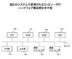
なお、図2に示した不正アクセス対策マネージャサイト100、不正アクセス通知エージェントサイト200、及び不正アクセス対策実施エージェントサイト300は、いずれも例えば図3に示すようなハードウェア構成を有するコンピュータを用いて構成することができる。
【0099】
図3について説明する。
同図に示すコンピュータはCPU601、RAM602、ROM603、HDD604、入力部605、出力部606、通信インタフェースA607、及び通信インタフェースB608がバス609を介して相互に接続されて構成されており、CPU601による管理の下で相互にデータ授受を行うことができる。
【0100】
CPU(Central Processing Unit )601はこのコンピュータ全体の動作制御を司る中央処理装置である。
RAM(Random Access Memory)602は、各種の制御プログラムをCPU601が実行するときにワークメモリとして使用され、また各種のデータの一時的な格納領域として必要に応じて用いられるメインメモリとしても使用されるメモリである。
【0101】
ROM(Read Only Memory)603はCPU601によって実行される基本制御プログラムが予め格納されているメモリであり、このコンピュータの起動時にCPU601がこの基本制御プログラムを実行することによってこのコンピュータ全体の動作の基本的な制御がCPU601によって行えるようになる。
【0102】
HDD(Hard Disk Drive )604は、各種のデータを記録しておくデータベースとして利用されるハードディスク装置である。また、HDD604にはCPU601によって実行される各種の制御プログラムが予め格納されている。
【0103】
入力部605は外部からの入力を受け取ってその入力の内容をCPU601に渡すものであり、必要に応じ、例えばキーボードやマウスなどといったこのコンピュータを操作する操作者からの指示を受け取る入力装置、あるいはFD(Flexible Disk)、CD−ROM(Compact Disc-ROM)、DVD−ROM(Digital Versatile Disc-ROM)、MO(Magneto-Optics)ディスクなどといった可搬型の記録媒体の読出装置を備えて構成される。
【0104】
出力部606はCPU601からの指示に応じた出力を行うものであり、例えば各種データを表示するCRT(Cathode Ray Tube)やLCD(Liquid Crystal Display)を備えて構成される表示装置や各種データを印刷して表示するプリンタ装置などである。
【0105】
なお、このコンピュータを不正アクセスマネージャサイト100として使用する場合には、管理端末101を入力部605や出力部606として利用してもよい。
【0106】
通信インタフェースA607は、このコンピュータをISPネットワーク500に接続して他のシステムとの間でのデータ授受を行う際の通信管理を行うものである。
【0107】
通信インタフェースB608は、このコンピュータを不正アクセス対処システム専用ネットワーク400に接続してISPネットワーク500に設けられている不正アクセス対処システムを構成する他のサイトとの間、あるいは隣接ネットワークに設けられている不正アクセス対処システムとの間でデータ授受を行う際の通信管理を行うものである。
【0108】
図3に示すコンピュータは以上の各構成要素を備えて構成される。
以下、図2に示した不正アクセス対処システムを構成する各サイトで前述した各種のプログラムを実行することによって構成される各部によって行われる処理の内容について説明する。
【0109】
なお、図2に示した不正アクセス対処システムでは、これより説明するトラフィックモニター手順、不正アクセス通知手順、不正アクセス対策制御手順、不正アクセス対策記録手順が並行して行われる。
【0110】
まず図4について説明する。同図はトラフィックモニターエンジン312によって行われるトラフィックモニター手順の内容をフローチャートで示したものである。
【0111】
まず、S101においてスレッドの分岐が行われ、その一方ではS102の繰り返し手順が、他方ではS103からS105にかけての繰り返しの手順が、それぞれ実行される。
【0112】
S102では、境界ルータ503へ流入しているトラフィックであるIP(Internet Protocol )パケット(以下、単に「パケット」と称することとする)がキャプチャー(捕獲)される。以降、S102の手順が繰り返されて境界ルータ503に流入するパケットが全てキャプチャーされる。
【0113】
S103では、S103からS105にかけてのスレッドの実行が一定の時刻レンジだけ、例えば10分間だけスリープ(停止)され、その後、所定の時刻レンジが経過したときにS104の手順に進む。
【0114】
S104では、S102の処理によってキャプチャーされているパケットの数が、接続ID、時刻レンジ、SrcIP、DistIP、及びDistPortをキーにして計数され、続くS105においてその計数の結果を示すデータが監視情報としてトラフィックDB320に格納される。このS105の手順が完了した後にはS103へ手順を戻して上述した手順が繰り返される。
【0115】
ここで図5について説明する。同図は上述したS105の手順によってデータの格納が行われるトラフィックDB320のデータ構造を示している。同図に示すように、トラフィックDB320にはレコード毎に「接続ID」、「時刻レンジ」、「SrcIP」、「DistIP」、「DistPort」、及び「Count」の各フィールドが設けられている。
【0116】
接続IDは、ISPネットワーク500の利用者に個別に割り当てられている識別子である。接続IDと計数対象とするパケットとの関係は、そのパケットに示されているSrcIPを運用管理システム501に送付して問い合わせを行うことによって運用管理システム501から得ることができる。
【0117】
時刻レンジはパケットの計数の開始時刻及び終了時刻の組である。
SrcIPは計数対象とするパケットに示されている送信元のIPアドレスである。
【0118】
DistIPは計数対象とするパケットに示されている宛先のIPアドレスである。
DistPortは計数対象とするパケットに示されている宛先のポート番号である。
【0119】
Countは「時刻レンジ」に示されている時間内に境界ルータ503に流入した計数対象とするパケットの数である。
図5に示されているデータ例のうち第一行目のレコードについて解説すると、接続IDとして「ABC01234」が割り当てられているISPネットワーク500の利用者は、「10:00−10:10」の時間内に、送信元のIPアドレスが「202.248.20.254」、宛先のIPアドレスが「202.248.20.68」、そして宛先のポート番号が「80」である「1456」個のパケットを境界ルータ503に流入させたことを示している。
【0120】
なお、トラフィックDB320には上述したデータが境界ルータ503毎に格納される。
以上のトラフィックモニター手順が行われることによって、境界ルータ503に流入するパケットの監視が行われる。
【0121】
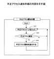
次に図6について説明する。同図は不正アクセス通知エンジン211によって行なわれる不正アクセス通知手順の内容をフローチャートで示したものである。
まず、S201において、IDS502の不正アクセスイベントのチェックが行われ、続くS202において不正アクセスの検知がIDS502によってなされたか否かが判定される。この結果、不正アクセスの検知がされたと判定された(判定結果がYes)ならばS203に手順を進め、不正アクセスの検知がされていないと判定された(判定結果がNo)ならばS201へ手順を戻して上述した手順が繰り返される。
【0122】
S203では、検知された不正アクセスについての通知が不正アクセス対策マネージャサイト100の不正アクセス対策制御部111へ行われる。その後はS201へ手順を戻して上述した手順が繰り返される。
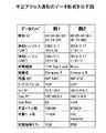
【0123】
ここで図7について説明する。同図は上述したS203の手順によって不正アクセス対策制御部111へ行われる不正アクセスの通知のデータ形式を示している。同図に示すように、この不正アクセス通知には、「検知ID」、「時刻レンジ・スタート」、「時刻レンジ・エンド」、「攻撃種別」、「組織名」、「所属ISP」、「ターゲットプロトコル」、「SrcIP」、「DistPort」、「不正パケット数」、「攻撃ツール名」、「対策解除ポリシー」の各情報が含まれている。なお、これらのデータはIDS502から得ることができる。
【0124】
検知IDは、不正アクセスの検知がなされる度にIDS502によってその不正アクセスに対して付与される一意な識別子であり、この検知IDによってDDoS攻撃を個別に特定する指標とすることができる。
【0125】
時刻レンジ・スタート及び時刻レンジ・エンドは、それぞれ不正アクセスに係るパケットが最初に検知された日時及びこの日時から所定の時間(例えば10分間)が経過したときの日時であり、図7の例ではこれらの日時がグリニッジ標準時(GMT)で示されている。
【0126】
攻撃種別は、検知された不正アクセスであるDDoS攻撃の詳細種別である。組織名は、不正アクセスを受けているシステムが属している組織の組織名である。
【0127】
所属ISPは、不正アクセスを受けているシステムが属している組織が所属しているISPの名称である。
ターゲットプロトコルは不正アクセスが攻撃を受けているシステムへの接続に利用しているプロトコルである。
【0128】
SrcIPは不正アクセスに係るパケットに示されている送信元のIPアドレスである。
DistIPは不正アクセスに係るパケットに示されている宛先のIPアドレスである。
【0129】
DistPortは不正アクセスに係るパケットに示されている宛先のポート番号である。
不正パケット数は検知IDで特定される不正アクセスに係るパケットの数である。
【0130】
攻撃ツール名は、不正アクセスに使用されているDDoS攻撃ツールのツール名である。
対策解除ポリシーは、この不正アクセスが停止してからこの対策を解除するまでの時間である。この時間はISPネットワーク500におけるセキュリティポリシーで許容される範囲内で例えば不正アクセスを受けている顧客からの指示により予め設定される。
【0131】
図7に示されているデータ例のうちの例1の不正について解説すると、IDS502によって検知された「00−00−0E−82−2E−74−001」なる検知IDで特定される不正アクセスは、「2003/2/1・16:01:16」から検知された「TCP Syn Flood」攻撃であり、この攻撃は「ISP ABC」に属する「CompamyA」への「TCP」プロトコルによるものであって、攻撃元は「TFN2K」なる攻撃ツールを使用しており、送信元のIPアドレスが「10.4.120.Z」、宛先のIPアドレスが「192.168.X.Y」、宛先のポート番号が「80」であるパケットが「2003/2/1・16:11:16」までの間に「156789」個送りつけられてきたこと、この不正アクセスについての対策は当該不正アクセスが停止してからも「10分間」は継続して実施すべきことを示している。
【0132】
以上の不正アクセス通知手順が行われることによって、IDS502による顧客ネットワークへの不正アクセスの検知の内容が不正アクセス対策マネージャサイト100の不正アクセス対策制御部111へ通知される。
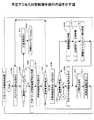
【0133】
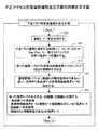
次に図8について説明する。同図は不正アクセス対策制御部111によって行われる不正アクセス対策制御手順の内容をフローチャートで示したものである。まず、S301において、不正アクセス通知エージェントサイト200からの不正アクセスの通知をひとつ取り出す。
【0134】
S302では、この取り出された不正アクセス通知に示されている前述した検知IDが参照され、この検出IDが過去に取得していた不正アクセス通知に示されていたか否か、より具体的にはこの検知IDと同一のものがLogDB140に記録されているか否かが判定される。そして、この判定結果がYesならばS314に手順が進み、NoならばS303に手順が進む。
【0135】
S303では不正アクセス対策実施場所決定手順が実行される。この手順の詳細は図9にフローチャートで示されている。
以下、この図9の手順を先に説明する。
【0136】
まず、S321において、運用管理システム501に対する問い合わせが行われて、ISPネットワーク500に設置されている境界ルータ503の一覧が取得される。
【0137】
S322では、不正アクセス対策実施エージェントサイト300に対する問い合わせが行われ、図8のS301の手順において取り出された不正アクセス通知に示されていた、時刻レンジ、SrcIP、DistIP、及びDistPortの一致しているレコードをトラフィックDB320から抽出する。そして、その抽出されたレコードに示されていたトラフィックが流入していた境界ルータ503を残してそのほかの境界ルータ503を前の手順で取得されていた境界ルータ503の一覧から除外する。
【0138】
S323では、先の一覧に残されている境界ルータ503から非常時接続利用者用端末のために設けられているもの(非常時接続境界ルータ)が抽出され、抽出された非常時接続境界ルータについてのトラフィックDB320の格納データから、前述した不正アクセス通知に関係しているデータレコードに示されている接続IDが取得される。
【0139】
S324では、前の手順で取得された接続IDで特定される利用者がISPネットワーク500に現在接続しているかどうかの問い合わせが運用管理システム501へ行われる。そして、この利用者がISPネットワーク500に現在接続しているのであればこの利用者によって現在使用されている非常時接続利用者端末からのパケットが流入している非常時接続境界ルータを抽出して先の一覧に残し、一方、この利用者が現在はISPネットワーク500に接続していないのであれば、この利用者によって使用されていた非常時接続利用者端末からの不正アクセスを流入させていた非常時接続境界ルータを先の一覧から除外する。
【0140】
S325では、一覧に残されている境界ルータ503の各々の接続先に基づいて、先の通知に係る不正アクセスについての対策を自組織で実施するか、あるいはこの対策の実施を他組織に依頼するかを分類する。
【0141】
この分類の基準は、より具体的には、一覧に残されている境界ルータ503が非常時接続境界ルータであるか、あるいはISPネットワーク500とは信頼関係のない隣接ISPとの境界に設置されているISP境界ルータであるならば、この境界ルータ503において自組織でこの対策を実施するものとする。一方、一覧に残されている境界ルータ503がISPネットワーク500と信頼関係にある隣接ISPとの境界に設置されているISP境界ルータであるならば、このISP境界ルータでは対策を行わずにその隣接ISPにこの対策の実施を依頼するものとする。この手順によって前述した通知に係る不正アクセスについての対策を実施する場所が全て決定される。
【0142】
S325の手順を終えた後には図8の手順へ戻る。
図8のS304では、上述した不正アクセス対策実施場所決定手順で求めた、対策実施場所が取り出される。
【0143】
S305では、S304の手順で取り出された対策実施場所のうち、未対策のまま残されている場所の数が0よりも大きいか否かが判定され、この判定結果がYes、すなわち未対策の場所が残されているのであればS306に手順を進める。一方、この判定結果がNo、すなわち対策を実施すべき全ての場所での対策が完了したならばS301へ手順を戻して上述した手順が繰り返される。
【0144】
S306では、S304の手順で取り出された対策実施場所のうち、未対策のまま残されている場所が一つ取り出される。
S307では、前の手順で取り出された場所が、自組織でこの対策を実施するとしていた境界ルータ503であるか否かが判定され、この判定結果がYesならばS308に手順を進める。一方、この判定結果がNo、すなわちこの場所がその隣接ISPにこの対策の実施を依頼するものとしたISP境界ルータであったならばS309に手順を進める。
【0145】
S308では、前の手順で取り出された場所である境界ルータ503を制御する不正アクセス対策実施エージェントサイト300に対して不正アクセス対策実施要求が送付され、その後はS312に手順が進む。
【0146】
この不正アクセス対策実施要求には対策を実施させる境界ルータ503を特定する情報が示されており、更にS301の処理で取り出されていた不正アクセス通知が添付されている。この要求を受け取った不正アクセス対策実施エージェントサイト300では、不正アクセス対策実施エンジン311によって不正アクセス対策実施手順が実行される。
【0147】
不正アクセス対策実施手順の詳細は図10にフローチャートで示されている。以下、この図10の手順を先に説明する。
まず、S401において、不正アクセス対策マネージャサイト100から送られてきた不正アクセス対策実施要求が取得される。
【0148】
S402では、運用管理システム501に対する問い合わせが行われ、運用管理システム501から送られてくる不正アクセス対策実施要求に示されていた境界ルータ503を制御するために必要な固有情報、例えばこの境界ルータ503の機器種別、機器管理のための管理者ID及びパスワード等が取得される。
【0149】
S403では、前の手順によって取得された固有情報を使用して境界ルータ503が制御され、不正アクセス対策実施要求に添付されていた不正アクセス通知に含まれるSrcIP、DistIP、DistPort、攻撃種別情報に基づいて、この通知に係る不正アクセスと同一のパケットの通過を遮断するフィルタを境界ルータ503が設定される。
【0150】
S404ではスレットの分岐が行われ、その一方ではS401からS403にかけての繰り返しの手順が実行され、他方ではS405からS408にかけての手順が実行される。
【0151】
S405では、前述したS403の手順で設定したフィルタの状況が境界ルータ503から取り出される。
S406では、前のステップで取り出されたフィルタの状況から、対策解除時間閾値を超えて不正アクセスであるパケットが継続して境界ルータ503に到来していないかどうかが判定され、この判定結果がYes、すなわち対策解除時間閾値を超えて不正アクセスであるパケットが継続して到来していないのであればS407に手順を進め、一方、この判定結果がNo、すなわち不正アクセスであるパケットが依然として到来しているかあるいは不正アクセスであるパケットが到来していない継続時間が対策解除時間閾値に未だ満たないときにはS405へ手順を戻して上述した手順が繰り返される。なお、対策解除時間閾値については後述する。
【0152】
S407では、境界ルータ503が制御されて前述したS403の手順で設定したフィルタが解除される。
S408では、不正アクセス対策マネージャサイト100の不正アクセス対策記録制御部112へログ要求が送付され、対策の実施完了の記録の依頼が行われる。なお、このログ要求には、S301の手順によって取得された不正アクセス通知が添付される。
【0153】
S408の手順を終えた後にはS404の手順によって分岐させたS405からS408にかけてのスレッドを終了させる。
以上の不正アクセス対策実施手順が行われることによって、不正なアクセスへの対策が実施されて顧客ネットワークが不正なアクセスから保護される。
【0154】
図8の手順の説明へ戻る。
前述したS307の手順における判定の結果がNoであったとき、すなわち前述したS306の手順において取り出された場所が、不正アクセスについての対策の実施を隣接ISPに依頼するものとしたISP境界ルータであったときにはS309において組織間認証手順が実行される。この手順の詳細は図11にフローチャートで示されている。
【0155】
以下、この図11の手順を先に説明する。
まず、S331においてサーバ認証処理が証明書120を用いて行われ、対策の依頼先である隣接ISP(サーバ)が確かに信頼関係にあるISPであって悪意あるサイトのなりすましでないことの確認が行われる。
【0156】
続くS332ではクライアント認証処理が証明書120を用いて行われ、対策依頼元であるISPネットワーク500(クライアント)が確かに信頼関係にあるISPで、悪意あるサイトのなりすましでないことの確認が対策の依頼先であるISPで行われる。
【0157】
このS332の手順が終了したときには図8の手順へ戻る。
以上の組織間認証手順が行われることによって、不正アクセス対策に関する情報の悪意あるサイトによるなりすましでの窃取が防止される。
【0158】
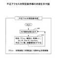
図8においてS309に続いて行われるS310では組織間ポリシー交換手順が実行される。この手順の詳細は図12にフローチャートで示されている。
以下、この図12の手順を先に説明する。
【0159】
まず、S341において、第三者による情報の解読を不可能にするために、対策依頼元であるISPネットワーク500と対策依頼先である隣接ISPとの間で暗号アルゴリズムの交換が行われる。
【0160】
S342では、対策依頼元であるISPネットワーク500と対策依頼先である隣接ISPとの間で自己の対策解除時間閾値の交換が行われ、そのうちの短いものが両者間での対策解除時間閾値として採用される。
【0161】
ここで対策解除時間閾値にについて説明する。
対策解除時間閾値とは、ある不正アクセスが検知されなくなってから後にどの程度の時間までその不正アクセスに対する対策を継続するかを示す閾値である。この閾値は自己のネットワーク運用におけるセキュリティポリシーに従って各ISPで独自に設定されるが、ISP間で異なる値が設定されている場合には、本実施形態においてはそのうちのより短い時間を示している閾値を、その両者によって伝送されている不正アクセスに対して採用することとする。これは、閾値を長時間とすればそれだけ不正アクセスではない正規のアクセスも遮断してしまうおそれが長く継続してしまうことを考慮したものである。
【0162】
従って、例えばPolicy130に示されている対策依頼元の対策解除時間閾値が10分に設定されており、一方、対策依頼先の対策解除時間閾値が20分に設定されている場合には、その両者によって伝送されている不正アクセスについての対策解除時間閾値としては10分が採用されることになる。
【0163】
なお、このようにして決定された対策解除時間閾値よりも、前述した不正アクセス通知に示されていた対策解除ポリシーの値の方がより短い時間を示していたときには、顧客の指示に従うため、この対策解除ポリシーの値を対策解除時間閾値として採用する。
【0164】
S343では、対策依頼元であるISPネットワーク500と対策依頼先である隣接ISPとの間でタイムゾーン(地域別時間帯情報)の交換が行われる。これは、双方で対策内容の記録を行うときの時刻情報をローカル時間で表わすことを可能にして利便性を向上させる等の用途のために行われるものである。
【0165】
このS343の手順が終了したときには図8の手順へ戻る。
以上の組織間ポリシー交換手順が行われることによって、ネットワーク運用に関するセキュリティポリシーに組織間で違いが存在していても、その違いを調整した上での不正アクセスに対する対策を依頼先に実施してもらうことができるようになる。
【0166】
図8においてS310に続いて行われるS311では、前述したS301の手順において取り出された不正アクセス通知が、対策依頼先である隣接ISPへ転送される。なお、このとき、S301の手順において取り出された不正アクセス通知に示されている対策解除ポリシーの値と、前述した組織間ポリシー交換手順の実行によって採用された対策解除時間閾値とが異なっているときには、このときの対策解除時間閾値を対策解除ポリシーの値として上書きした上で対策依頼先である隣接ISPへ転送するようにする。
【0167】
S312では不正アクセス対策記録制御部112へログ要求が送付され、上述したS308の手順またはS309からS311にかけての手順で行われた処理の内容の記録の依頼が行われる。なお、このログ要求には、S301の手順によって取得された不正アクセス通知が添付される。
【0168】
S313では、S303の不正アクセス対策実施場所決定手順で求めた対策実施場所数を1減らし、その後はS305へ手順を戻して上述した処理が繰り返される。
【0169】
ところで、前述したS302の手順における判定の結果がYesであったときには、その後も不正アクセス通知の転送がISP間で繰り返される(不正アクセス通知がループしている)だけで不正アクセスに対する対策が全くなされてないおそれがあると見ることができる。
【0170】
そこで、この場合には、まず、S314において、不正アクセス対策記録制御部112へログ要求が送付され、ループしている不正アクセス通知を取得した旨の記録の依頼が行われる。なお、このログ要求には、S301の手順によって取得された不正アクセス通知が添付される。
【0171】
その後は、S315において、S301で取り出された不正アクセス通知を送付してきた通知元(すなわち不正アクセス対策依頼の依頼元)のISPの不正アクセス対策マネージャサイト100に指示を与えて、そこで実行されている不正アクセス対策制御手順をS308から開始させることにより、この不正アクセス通知に係る不正アクセスに対する対策をそのISP内で実施させるようにする。
【0172】
以上の不正アクセス対策制御手順が行われることによって、不正なアクセスへの対策の実施が指示されて顧客ネットワークが不正なアクセスから保護される。
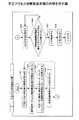
次に図13について説明する。同図は不正アクセス対策記録制御部112によって行われる不正アクセス対策記録手順の内容をフローチャートで示したものである。
【0173】
まず、S501において、不正アクセス対策制御部111や不正アクセス対策実施エージェントサイト300の不正アクセス対策実施エンジン311から送られてくるログ要求が取り出される。
【0174】
S502では、取り出されたログ要求に基づいて、時刻、アクション、検出ID、時刻レンジ、SrcIP、DistIP、DistPort、不正パケット数、攻撃種別をログに記録してLogDB140に格納する。なお、ここで、「アクション」とは、例えば対策の実施、対策の転送(隣接ISPへの対策の依頼)、対策の解除、あるいは対策の中止など、どのような処置が実行されたときにログの記録が要求されたかを示す情報である。
【0175】
このS502の手順を終えた後にはS501へと手順を戻し、以降は上述したログ要求の取り出しとログへの記録の手順が繰り返される。
以上の不正アクセス対策記録手順が行われることにより、ISPネットワーク500の管理者は顧客ネットワークに対する不正アクセスへの対処の状況をこの履歴の記録から把握することができるようになる。
【0176】
なお、図2は本発明を実施する不正アクセス対処システムの各構成要素によって実行される各種の制御プログラムをコンピュータで読み取り可能な記録媒体に記録させ、その制御プログラムを記録媒体からコンピュータに読み出させて実行させることによって本発明を実施するようにしてもよい。
【0177】
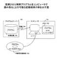
記録させた制御プログラムをコンピュータで読み取ることの可能な記録媒体の例を図14に示す。このような記録媒体としては、データやプログラム等の情報を電気的、磁気的、光学的、機械的、または化学作用によって蓄積し、コンピュータから読み取ることができるものであればよく、このような記録媒体としては、同図に示すように、例えば、コンピュータ701に内蔵若しくは外付けの付属装置として備えられるRAM若しくはROM又はハードディスク装置などのメモリ702、あるいはフレキシブルディスク、MO(光磁気ディスク)、CD−ROM、CD−R/W、DVD、8mmテープ、メモリカードなどといった可搬型記録媒体703等が利用できる。
【0178】
また、記録媒体は通信回線704を介してコンピュータ701と接続される、プログラムサーバ705として機能するコンピュータが備えている記憶装置706であってもよい。この場合には、制御プログラムを表現するデータ信号で搬送波を変調して得られる伝送信号を、プログラムサーバ45から伝送媒体である通信回線704を通じて伝送するようにし、コンピュータ701では受信した伝送信号を復調して制御プログラムを再生することで当該制御プログラムを実行できるようになる。
【0179】
ここで、伝送媒体としては、有線通信媒体、例えば、同軸ケーブルおよびツイストペアケーブルを含む金属ケーブル類、光通信ケーブル等、または、無線通信媒体、例えば、衛星通信、地上波無線通信等のいずれでもよい。
【0180】
また、搬送波は、データ通信信号を変調するための電磁波または光である。但し、搬送波は直流信号でもよい。この場合にはデータ通信信号は搬送波がないベースバンド波形になる。したがって、搬送波に具現化されたデータ通信信号は、変調されたブロードバンド信号を変調されていないベースバンド信号(電圧0の直流信号を搬送波とした場合に相当)のいずれでもよい。
【0181】
その他、本発明は、上述した実施形態に限定されることなく、本発明の要旨を逸脱しない範囲内で種々の改良・変更が可能である。
(付記1) 自己の通信ネットワークより公開されているサービスに対する不正なアクセスの流入路の探索を行う探索手段と、
前記サービスを前記不正なアクセスから保護するための対策を実施する場所の決定を前記探索の結果に基づいて行う決定手段と、
前記不正なアクセスを自己の通信ネットワークに流入させている流入元で前記対策を実施するとの前記決定に応じて該決定を該流入元へ通知する通知手段と、を有することを特徴とする不正アクセス対処システム。
【0182】
(付記2) 自己の通信ネットワークより公開されているサービスに対する不正なアクセスの流入路の探索を行う探索処理と、
前記サービスを前記不正なアクセスから保護するための対策を実施する場所の決定を前記探索の結果に基づいて行う決定処理と、
前記不正なアクセスを自己の通信ネットワークに流入させている流入元で前記対策を実施するとの前記決定に応じて該決定を該流入元へ通知する通知処理と、をコンピュータに行わせるための不正アクセス対処処理プログラム。
【0183】
(付記3) 前記探索処理は、前記不正なアクセスが検知されたときに前記探索の処理を前記コンピュータに行わせることを特徴とする付記2に記載の不正アクセス対処処理プログラム。
【0184】
(付記4) 前記探索処理は、前記不正なアクセスの検知が通知されたときに前記探索の処理を前記コンピュータに行わせることを特徴とする付記2に記載の不正アクセス対処処理プログラム。
【0185】
(付記5) 前記探索処理は、前記自己の通信ネットワークで伝送されているトラフィックの監視情報と前記不正なアクセスの内容を示す不正アクセス情報とに基づいて前記流入路を探索する処理を前記コンピュータに行わせることを特徴とする付記2に記載の不正アクセス対処処理プログラム。
【0186】
(付記6) 前記監視情報は、前記自己の通信ネットワークと該自己の通信ネットワークに隣接する通信ネットワークとの境界に配置されている境界ルータの位置情報と、該境界ルータを通過して該自己の通信ネットワークへ流入したトラフィックについての監視情報とを少なくとも含むことを特徴とする付記5に記載の不正アクセス対処処理プログラム。
【0187】
(付記7) 前記通知処理は、前記不正なアクセスの流入元との間で相互認証を行った後に前記決定を該流入元へ通知する処理を前記コンピュータに行わせることを特徴とする付記2に記載の不正アクセス対処処理プログラム。
【0188】
(付記8) 前記通知処理は、前記不正なアクセスの流入元との間で各々のネットワーク運用におけるセキュリティポリシーに関する情報を交換した後に前記決定を該流入元へ通知する処理を前記コンピュータに行わせることを特徴とする付記2に記載の不正アクセス対処処理プログラム。
【0189】
(付記9) 前記セキュリティポリシーに関する情報は、前記不正なアクセスが検知されなくなってから該不正なアクセスに対する前記対策を解除するまでの時間を示す情報であることを特徴とする付記8に記載の不正アクセス対処処理プログラム。
【0190】
(付記10) 前記セキュリティポリシーに関する情報によって示されている時間が前記自己のネットワークと前記流入元とで異なっているときには、両者のうち短い方の時間を、前記不正なアクセスが検知されなくなってから該不正なアクセスに対する前記対策を解除するまでの時間とすることを特徴とする付記9に記載の不正アクセス対処処理プログラム。
【0191】
(付記11) 前記通知処理は、前記決定と共に、前記不正なアクセスが検知されなくなってから該不正なアクセスに対する前記対策を解除するまでの時間を示す情報を前記流入元へ通知する処理を前記コンピュータに行わせることを特徴とする付記10に記載の不正アクセス対処処理プログラム。
【0192】
(付記12) 前記通知処理は、前記不正なアクセスの流入路とは異なる通信経路を用いて前記決定を該不正なアクセスの流入元へ通知する処理を前記コンピュータに行わせることを特徴とする付記2に記載の不正アクセス対処処理プログラム。
【0193】
(付記13) 前記通知処理は、前記自己の通信ネットワークに前記不正なアクセスを流入させている流入元で前記対策を実施する決定がされたときに、該決定を該流入元へ通知するか否かの判定を前記コンピュータに行わせ、
前記通知処理の実行によって前記決定を前記流入元へ通知しないとの判定がされたときに、前記サービスを前記不正なアクセスから保護するための対策を前記自己の通信ネットワーク内で実施させる不正アクセス対策実施制御処理を前記コンピュータに更に行わせる、
ことを特徴とする付記2に記載の不正アクセス対処処理プログラム。
【0194】
(付記14) 前記判定は、予め与えられている前記流入元についての判定情報に基づいて行われることを特徴とする付記13に記載の不正アクセス対処処理プログラム。
【0195】
(付記15) 前記自己の通信ネットワーク内で前記対策を実施するとの前記決定に応じて、該サービスを該不正なアクセスから保護するための対策を該自己の通信ネットワーク内で実施させる不正アクセス対策実施制御処理を前記コンピュータに更に行わせることを特徴とする付記2に記載の不正アクセス対処処理プログラム。
【0196】
(付記16) 前記不正アクセス対策実施制御処理は、前記不正なアクセスの発信元が接続しているPOP(ポイント・オブ・プレゼンス)境界ルータにおいて前記対策を実施させるための処理を前記コンピュータに行わせることを特徴とする付記15に記載の不正アクセス対処処理プログラム。
【0197】
(付記17) 前記不正アクセス対策実施制御処理は、前記不正なアクセスの発信元が接続しているPOP境界ルータを、前記自己の通信ネットワークの運用の管理を行っている運用管理システムから得られる情報に基づいて特定する処理を前記コンピュータに行わせることを特徴とする付記16に記載の不正アクセス対処処理プログラム。
【0198】
(付記18) 前記自己の通信ネットワークとは異なる他の通信ネットワークより公開されているサービスに対する不正なアクセスを該他の通信ネットワークへ流入させている決定の通知を取得する通知取得処理を前記コンピュータに更に行わせ、
前記不正アクセス対策実施制御処理は、前記通知取得処理によって前記通知が取得されたときには、前記他の通信ネットワークより公開されているサービスを該通知に係る該不正なアクセスから保護するための対策を前記自己の通信ネットワーク内で実施させる処理を前記コンピュータに行わせる、
ことを特徴とする付記15に記載の不正アクセス対処処理プログラム。
【0199】
(付記19) 前記不正アクセス対策実施制御処理の実行によって実施させた前記対策は、前記不正アクセスの検知がされなくなったときから予め設定されている時間が経過した後には解除されることを特徴とする付記15に記載の不正アクセス対処処理プログラム。
【0200】
(付記20) 前記予め設定されている時間は、前記自己の通信ネットワークと前記他の通信ネットワークとの各々のネットワーク運用におけるセキュリティポリシーに基づいて設定されていることを特徴とする付記19に記載の不正アクセス対処処理プログラム。
【0201】
(付記21) 前記自己の通信ネットワークと前記他の通信ネットワークとの各々のネットワーク運用におけるセキュリティポリシーに基づいて設定されている時間が両者間で異なっているときには、前記不正アクセスの検知がされなくなったときから両者のうち短い方の時間が経過した後には解除されることを特徴とする付記20に記載の不正アクセス対処処理プログラム。
【0202】
(付記22) 前記自己の通信ネットワークとは異なる他の通信ネットワークより公開されているサービスに対する不正なアクセスを該他の通信ネットワークへ流入させている決定の通知を取得する通知取得処理を前記コンピュータに更に行わせ、
前記探索処理は、前記通知取得処理によって前記通知が取得されたときには、該通知に係る不正なアクセスの自己の通信ネットワークにおける流入路を探索する処理を前記コンピュータに行わせ、
前記決定処理は、前記通知取得処理によって前記通知が取得されたときには、前記他の通信ネットワークより公開されているサービスを該通知に係る不正なアクセスから保護するための対策を実施する場所を前記探索の結果に基づいて決定する処理を前記コンピュータに行わせ、
前記通知処理は、前記通知取得処理によって前記通知が取得されたときには、該通知に係る不正なアクセスを前記自己の通信ネットワークに流入させている流入元で前記対策を実施する決定に応じて該決定を該流入元へ通知する処理を前記コンピュータに行わせる、
ことを特徴とする付記2に記載の不正アクセス対処処理プログラム。
【0203】
(付記23) 前記通知取得処理の実行によって取得された通知が過去に取得されたものと同一の通知であるときに、前記自己の通信ネットワーク若しくは前記他の通信ネットワークより公開されているサービスを該通知に係る不正なアクセスから保護するための対策を該通知の通知元の通信ネットワーク内で実施させる不正アクセス対策実施制御処理を前記コンピュータに更に行わせることを特徴とする付記22に記載の不正アクセス対処処理プログラム。
【0204】
(付記24) 前記通知処理は、前記決定を通知するときに該通知に係る不正なアクセスを一意に特定する情報を併せて通知する処理を前記コンピュータに行わせることを特徴とする付記23に記載の不正アクセス対処処理プログラム。
【0205】
(付記25) 前記通知処理の実行の履歴を記録する記録処理を前記コンピュータに更に行わせることを特徴とする付記2に記載の不正アクセス対処処理プログラム。
【0206】
(付記26) 自己の通信ネットワークより公開されているサービスに対する不正なアクセスの流入路の探索を行い、
前記サービスを前記不正なアクセスから保護するための対策を実施する場所の決定を前記探索の結果に基づいて行い、
前記不正なアクセスを自己の通信ネットワークに流入させている流入元で前記対策を実施するとの前記決定に応じて該決定を該流入元へ通知する、
ことを特徴とする不正アクセス対処方法。
【0207】
(付記27) 自己の通信ネットワークより公開されているサービスに対する不正なアクセスの流入路の探索を行う探索処理と、
前記サービスを前記不正なアクセスから保護するための対策を実施する場所の決定を前記探索の結果に基づいて行う決定処理と、
前記不正なアクセスを自己の通信ネットワークに流入させている流入元で前記対策を実施するとの前記決定に応じて該決定を該流入元へ通知する通知処理と、をコンピュータに行わせるための不正アクセス対処処理プログラムを記録した該コンピュータで読み取り可能な記録媒体。
【0208】
【発明の効果】
以上詳細に説明したように、本発明は、自己の通信ネットワークより公開されているサービスに対する不正なアクセスの流入路を探索し、このサービスをこの不正なアクセスから保護するための対策を実施する場所の決定をこの探索の結果に基づいて行い、この不正なアクセスを自己の通信ネットワークに流入させている流入元でこの対策を実施するとの決定に応じて該決定を該流入元へ通知する。
【0209】
こうすることにより、本発明によれば、不正アクセスの発信元にできるだけ近い場所での不正アクセス対策の実施が可能となる結果、分散型サービス不能化攻撃に効果的に対処することができるという効果を奏する。
【図面の簡単な説明】
【図1】本発明の原理構成を示す図である。
【図2】本発明を実施する不正アクセス対処システムの機能構成を示す図である。
【図3】図2のシステムで使用されるコンピュータのハードウェア構成例を示す図である。
【図4】トラフィックモニター手順の内容を示す図である。
【図5】トラフィックDBのデータ構造を示す図である。
【図6】不正アクセス通知手順の内容を示す図である。
【図7】不正アクセス通知のデータ形式を示す図である。
【図8】不正アクセス対策制御手順の内容を示す図である。
【図9】不正アクセス対策実施場所決定手順の内容を示す図である。
【図10】不正アクセス対策実施手順の内容を示す図である。
【図11】組織間認証手順の内容を示す図である。
【図12】組織間ポリシー交換手順の内容を示す図である。
【図13】不正アクセス対策記録手順の内容を示す図である。
【図14】記録させた制御プログラムをコンピュータで読み取ることの可能な記録媒体の例を示す図である。
【図15】従来の不正アクセス対処システムの概略を説明する図である。
【符号の説明】
10 自ISP
11、501 運用管理システム
12、100 不正アクセス対策マネージャサイト
12−1 探索手段
12−2 決定手段
12−3 通知手段
12−4 認証手段
12−5 セキュリティポリシー交換手段
12−6 不正アクセス対策実施制御手段
12−7 通知取得手段
12−8 記録手段
13、200 不正アクセス通知エージェントサイト
13−1 不正アクセス通知手段
14、502 IDS
15 顧客境界ルータ
16、18、300 不正アクセス対策実施エージェントサイト
16−1、18−1 トラフィックモニター手段
16−2、18−2 不正アクセス対策実施手段
17、2002、2003 ISP境界ルータ
19、3001、4001 POP境界ルータ
20、1000 顧客サイト
21、1001 Webシステム
22、1002 ファイヤウォール
30 隣接ISP
40 非常時接続利用者端末
101 管理端末
110 不正アクセス対策マネージャプログラム
111 不正アクセス対策制御部
112 不正アクセス対策記録制御部
113、313 IO制御部
120 証明書
130 Policy
140 LogDB
210 不正アクセス通知プログラム
211 不正アクセス通知エンジン
212 通信制御部
310 不正アクセス対策実施プログラム
311 不正アクセス対策実施エンジン
312 トラフィックモニターエンジン
320 トラフィックDB
400 不正アクセス対処システム専用ネットワーク
500 ISPネットワーク
503、2001 境界ルータ
601 CPU
602 RAM
603 ROM
604 HDD
605 入力部
606 出力部
607 通信インタフェースA
608 通信インタフェースB
609 バス
701 コンピュータ
702 メモリ
703 可搬型記録媒体
704 回線
705 プログラムサーバ
706 記憶装置
2000 ISP−A
3000 ISP−B
4000 ISP−C[0001]
BACKGROUND OF THE INVENTION
The present invention relates to an unauthorized access countermeasure technique in a communication network, and more particularly to an implementation technique of an unauthorized access countermeasure service provided to a customer by, for example, an Internet service provider (ISP), and particularly represented by a distributed service disablement attack. This is related to effective countermeasure implementation technology against unauthorized access attacks.
[0002]
[Prior art]
Denial of service (DoS) attack is an attack that stops or disables the system by deliberately sending a processing request that exceeds the allowable system resource limit. It is difficult to distinguish it from. In particular, an attack in which many attack sources are distributed on the network is called a distributed denial of service attack (DDoS: hereinafter referred to as “DDoS attack”). This DDoS attack is described in detail in
[0003]
The conventional countermeasure technologies for DDoS attacks can be classified into the following two methods, and each countermeasure technology can be further subdivided for each method.
[0004]
I. A method to replace components used in the current network
(1) Coping techniques performed by expanding IP packets
In addition to adding the round-trip route information to the IP packet, the search for the attack source is performed by replacing the router (Router) and the firewall (Firewall) with something that can understand the expanded IP packet from the current one. And a technique that enables equalization for each transmission source of request processing.
[0005]
(2) Coping techniques that do not extend IP packets
As a technique included in this technique, for example, the technique disclosed in
[0006]
II. A method of using the components used in the current network as they are
This method will be described with reference to FIG.
In the network configuration example shown in FIG. 15, the
[0007]
The Web system 1001 is connected to the
[0008]
Also, an attacker who intends to perform a DDoS attack on the Web system 1001 is a POP (Point of Point) managed by ISP-B3000, which is an Internet service provider adjacent to ISP-A2000 on the network. Presence) Access the border router to attack the Web system.
[0009]
On the other hand, a legitimate user who uses the service of the Web system 1001 accesses the POP border router managed by the ISP-
[0010]
(1) Countermeasure technology by the target customer site
This is an ISP-equipped device that implements unauthorized access detection technology used in IDS (Intrusion Detection System) and packet control (filtering, flow control, etc.) technology used in firewalls and routers. A technology that is arranged at the network boundary between the A2000 and the customer site 1000 (located in the
[0011]
(2) Coping technology by single ISP
This is because the IDS device is arranged at the network boundary between the ISP-
[0012]
(3) Coping technology by cooperation with multiple ISPs
This is because the administrator of ISP-A2000 who specified that the neighboring ISP from which the unauthorized access packet flowed in is ISP-B3000 by the above-mentioned technique for dealing with the single ISP, measures the administrator of ISP-B3000 manually by telephone. It is realized by requesting. Therefore, this is an unestablished technology.
[0013]
The location of technical information related to DDoS attacks is detailed in Non-Patent
By the way, it can be said that it is more effective to deal with the distributed service disablement attack in a place closer to the attack source on the route from the attack source to the target customer site. This is because, if measures are taken closer to the attack target site, the attack target site can be protected, but it cannot be disabled due to network congestion on the route or router processing delay. This is because, for those who use the Internet from the Internet, the service will be in the same state as when the service is disabled.
[0014]
[Patent Document 1]
JP 2002-164938 A
[Non-Patent Document 1]
"Trends in Denial of Service Attack Technology", by Kevin J Houle and George M. Weaver, [ online], October 2001, CERT Coordination Center, [February 17, 2003 search], Internet <URL: http://www.cert.org/archive/pdf/DoS_trends. pdf>
[0015]
[Non-Patent Document 2]
Dave Dittrich, "Distributed Denial of Service (DDoS) Attacks / tools", [online], [February 2003 Search on the 17th], Internet <URL: http://staff.washington.edu/dittrich/misc/ddos/>
[0016]
[Problems to be solved by the invention]
Among the methods described above, I.I. In this method, since a DDoS attack cannot be dealt with unless a router equipped with a new protocol is installed instead of a router used in the current network, the cost of replacing the router is high. Furthermore, there is a problem that it takes a long time before a new protocol and a router capable of handling the new protocol become widespread.
[0017]
In addition, since the reliability of communication cannot be ensured in a state where a DDoS attack has occurred, the technology disclosed in
[0018]
Among the methods described above, II. In this method, the following problems can be considered.
First, since the countermeasure technology by the attack target customer site implements a countermeasure at the boundary between the ISP and the attack target customer site, it cannot cope with network congestion in the ISP and a decrease in router processing capability. Therefore, the influence of the DDoS attack on other customers of the ISP cannot be prevented.
[0019]
In the example of FIG. 15, when a DDoS attack on the Web system 1001 by the attacker via the ISP-
[0020]
Further, in the coping technique by the single ISP, the countermeasure is implemented at the boundary between the ISP and the adjacent ISP, so that the influence on the network within the local ISP is minimized, but the network congestion in the adjacent ISP and the router Since it is impossible to cope with the deterioration of the processing capability, it is impossible to prevent the influence of the regular packet flowing from the adjacent ISP to the local ISP as a result. Furthermore, since countermeasures can be taken only at the network boundary that is always connected, it is impossible to correctly deal with an attack from an emergency connection network whose connection entity changes with time.
[0021]
In the example of FIG. 15, when a DDoS attack to the Web system 1001 by the attacker via the ISP-
[0022]
In addition, although the countermeasure technology based on the cooperation of multiple ISPs can implement countermeasures at a location closer to the source of the attack, at present, ISP administrators communicate with each other over the telephone and address each other's security policy to address the problem. Therefore, it takes a considerable amount of time for the countermeasure work. In addition, since there is no authentication method between ISP personnel, security problems such as reliability of operational information or impersonation arise. There is also a problem that work history does not remain when countermeasures are taken in cooperation between ISPs.
[0023]
The present invention has been made in view of such problems of the conventional technology.
That is, the problem to be solved by the present invention is to effectively deal with a distributed service denial-of-service attack by a plurality of ISPs cooperating to implement unauthorized access countermeasures as close as possible to an unauthorized access source. It is to provide the unauthorized access incoming call rejection technology.
[0024]
[Means for Solving the Problems]
Means for solving the above-described problem will be described with reference to FIG.
In FIG. 1, an own ISP (Internet service provider) 10 is an own communication network, and its operation is managed by an
[0025]
The web system 21 of the customer site 20 discloses a web service from its
[0026]
An IDS (intrusion detection system) 14 detects unauthorized access to the Web system 21 of the customer site 20 at the
[0027]
The unauthorized access agent site 13 is provided with unauthorized access notification means 13-1 as necessary, and sends information obtained from the
[0028]
The unauthorized access
[0029]
The unauthorized access countermeasure
[0030]
The unauthorized access countermeasure
[0031]
The unauthorized
[0032]
The unauthorized access countermeasure system, which is one of the aspects according to the present invention, includes search means 12-1 for searching for an inflow path of unauthorized access to a service published from its own communication network, and this unauthorized access to this service. If the measure 12-2 is determined based on the result of the search, and the countermeasure is implemented at the inflow source where the unauthorized access is flowing into the own communication network. The above-described problem is solved by including notification means 12-3 that notifies the inflow source of the determination in response to the determination.
[0033]
According to this configuration, countermeasures against unauthorized access to a service (web service by the web system 21) published from the own communication network (own ISP 10) is allowed to flow into the own communication network. Since the decision to implement at the inflow source is notified to the inflow source, countermeasures against unauthorized access can be implemented at a location closer to the inflow source, that is, the source of unauthorized access. Effective countermeasures can be taken.
[0034]
In the unauthorized access countermeasure system according to the present invention described above, the search unit 12-1 may perform the above-described search when the above-described unauthorized access is detected, or detection of unauthorized access. The above-described search may be performed when notified of the occurrence of the error.
[0035]
In FIG. 1, the unauthorized access is detected by the
[0036]
This makes it possible to take quick measures against unauthorized access.
Further, in the unauthorized access countermeasure system according to the present invention described above, the search means 12-1 is based on the monitoring information of traffic transmitted through its own communication network and the unauthorized access information indicating the content of the unauthorized access described above. Thus, the above-described inflow path may be searched.
[0037]
In FIG. 1, the monitoring information of traffic transmitted by the own communication network, that is, the
[0038]
Here, the monitoring information includes the position information of the border router arranged at the boundary between the own communication network and the communication network adjacent to the own communication network, and passes through the border router to the own communication network. It may include at least monitoring information about the inflowed traffic.
[0039]
In FIG. 1, the position information of the border router (ISP border router 17) is obtained from the
[0040]
Here, the traffic monitoring unit 16-1 uses the transmission source address, the transmission destination address, and the transmission destination port number as keys, for example, to determine the number of packets flowing in via the ISP border router 17 for each unit time and connection destination. By recording each packet, it is possible to grasp an inflow path of a packet in which a transmission source address is camouflaged.
[0041]
Further, the traffic monitoring means 18-1 also performs the same recording as the traffic monitoring means 16-1, thereby grasping inflow packets from the emergency connection
[0042]
Preferably, the traffic monitoring means 16-1 and 18-1 may obtain connection destination information in cooperation with the
In the unauthorized access countermeasure system according to the present invention described above, the notifying unit 12-3 notifies the inflow source of the determination described above after performing mutual authentication with the inflow source of the unauthorized access described above. It may be.
[0043]
In FIG. 1, this mutual authentication is performed by the authentication means 12-4. This prevents the above-mentioned decision notification from being stolen by a third party impersonating the inflow source.
[0044]
Here, the connection protocol with the inflow source for mutual authentication may be, for example, HTTPS (Hypertext Transfer Protocol Security) protocol, and the authentication method used in this mutual authentication is, for example, public key infrastructure (PKI: Public Key Infrastructure), and the electronic certificate is, for example, ITU (International Telecommunication Union) Recommendation X. 509 may be used.
[0045]
Further, in the unauthorized access countermeasure system according to the present invention described above, the notification unit 12-3 exchanges information on the security policy in each network operation with the unauthorized access inflow source described above, and then performs the determination described above. You may make it notify to this inflow source.
[0046]
In FIG. 1, the information regarding the security policy is exchanged by the security policy exchanging means 12-5. By doing so, even if there is a difference in the security policy with the inflow source, it is possible to request the inflow source to take measures against unauthorized access after adjusting the difference.
[0047]
Here, as the information regarding the security policy, the data encryption method information and the time zone information may be exchanged, or when the data encryption method is exchanged, the HTTPS protocol may be used.
[0048]
Further, the information on the security policy may be information indicating a time from when the unauthorized access is no longer detected until the countermeasure against the unauthorized access is canceled.
[0049]
In this way, even if there is a difference in the security policy regarding the time from when the unauthorized access is no longer detected until the countermeasure against the unauthorized access is released, the countermeasure according to the security policy is taken as the inflow source. Can be requested.
[0050]
At this time, if the time indicated by the information on the security policy is different between the own network and the inflow source, the shorter time of the two is used after the unauthorized access is not detected. You may make it the time until the said countermeasure with respect to access is cancelled | released.
[0051]
By doing so, it is possible to request the inflow source to take measures in accordance with the security policy that can be permitted by both the own network and the inflow source.
At this time, the notifying unit 12-3 notifies the inflow source of information indicating the time from when the unauthorized access is no longer detected to when the above-described countermeasure against the unauthorized access is canceled together with the above-described determination. It may be.
[0052]
By doing so, the inflow source is notified of the setting of this time according to the security policy that can be accepted by both the own network and the inflow source.
In the unauthorized access countermeasure system according to the present invention described above, the notifying unit 12-3 notifies the above-mentioned determination to the inflow source of unauthorized access using a communication path different from the above-described unauthorized access inflow path. You may make it do.
[0053]
Since the inflow path of unauthorized access may not be used as a communication path due to the influence of the DDos attack, the above-described determination can be notified to the inflow source even if such a case occurs. become.
[0054]
Further, in the unauthorized access countermeasure system according to the present invention described above, the notifying means 12-3 is determined to implement the countermeasure described above at the inflow source that is allowing the unauthorized access described above to flow into its own communication network. When the determination is made to notify the inflow source of the determination, and when the notification means 12-3 determines that the above-mentioned determination is not notified to the inflow source, You may make it further provide the unauthorized access countermeasure implementation control means 12-6 which makes the countermeasure for protecting from the unauthorized access mentioned above implement in own communication network.
[0055]
By doing so, for example, even if the above-described determination is notified to the inflow destination described above, even if the above-described countermeasure cannot be performed at the inflow destination, it is possible to appropriately cope with such unauthorized access. It becomes like this.
[0056]
Here, the determination described above may be performed based on determination information about the inflow source given in advance.
In this way, for example, when it is known in advance that the above-mentioned countermeasure cannot be taken at the inflow destination even if the above-mentioned determination is notified to the inflow destination, information indicating this is determined in advance. By giving it as information, it is possible to appropriately deal with such unauthorized access.
[0057]
Further, in the above-described unauthorized access countermeasure system according to the present invention, in response to the above-described determination that the above-described countermeasure is implemented in the own communication network, the countermeasure for protecting the service from the unauthorized access is taken. You may make it further provide the unauthorized access countermeasure implementation control means 12-6 performed in the communication network.
[0058]
By doing so, when the source of unauthorized access is made from within the own communication network (own ISP 10), it is possible to appropriately take measures against such unauthorized access within the own communication network. become.
[0059]
In FIG. 1, for example, when unauthorized access to the Web system 21 flows from the
[0060]
Here, the unauthorized access countermeasure implementation control means 12-6 may cause the above-mentioned countermeasure to be implemented in the POP (point of presence) border router to which the unauthorized access source is connected. Good.
[0061]
In FIG. 1, for example, when the emergency
[0062]
Here, the unauthorized access countermeasure implementation control means 12-6 manages the operation of the communication network (local ISP 10) of the
[0063]
In a POP (Point of Presence) connection, an identifier assigned to a terminal in order to identify a specific terminal on a communication network is generally different for each connection. Accordingly, since the emergency
[0064]
In addition, it further has a notification acquisition means 12-7 for acquiring a notification of a determination that an unauthorized access to a service published from another communication network different from its own communication network is allowed to flow into the other communication network. When the notification acquisition unit 12-7 acquires the above-described notification, the unauthorized access countermeasure implementation control unit 12-6 uses the above-mentioned unauthorized access related to the notification from the unauthorized access related to the notification. You may make it implement the countermeasure for protection within its own communication network.
[0065]
By doing so, the unauthorized access to the service disclosed by the above-mentioned other communication network flows into the other communication network, that is, the unauthorized access at a place closer to the source of the unauthorized access. Appropriate measures will be implemented.
[0066]
Further, the countermeasure implemented by the unauthorized access countermeasure implementation control means 12-6 may be canceled after a preset time has elapsed since the unauthorized access is no longer detected.
[0067]
Here, the preset time may be set based on the security policy in each network operation of the own communication network and the other communication networks described above.
[0068]
By doing so, the effect of receiving legitimate access due to countermeasures against unauthorized access is resolved after a predetermined time has elapsed since the unauthorized access stopped.
[0069]
At this time, when the time set based on the security policy in each network operation of the own communication network and the above-described other communication networks is different between the two, the unauthorized access is not detected. It may be canceled after the shorter time of both has elapsed.
[0070]
By doing this, the time until the effect of receiving legitimate access due to countermeasures against unauthorized access is resolved, the time according to the security policy that can be allowed in both the own communication network and other communication networks, Become.
[0071]
In addition, in the unauthorized access countermeasure system according to the present invention described above, a notification of a determination that unauthorized access to a service published from another communication network different from the own communication network is allowed to flow into the other communication network is sent. The search unit 12-1 further includes a notification acquisition unit 12-7 to acquire, and when the notification acquisition unit 12-7 acquires the above-described notification, an inflow of unauthorized access related to the notification into the own communication network When the notification is acquired by the notification acquisition unit 12-7, the determination unit 12-2 protects the service disclosed from the other communication network described above from unauthorized access related to the notification. A place for implementing measures to do is determined based on the result of the search described above, the notification means 12-3, When the above-described notification is acquired by the knowledge acquisition means 12-7, the determination is made according to the determination to implement the above-described countermeasure at the inflow source that has caused unauthorized access related to the notification to flow into its communication network. You may make it notify to an inflow origin.
[0072]
By doing so, the unauthorized access to the services disclosed by the above-mentioned other communication networks is allowed to flow into the upstream communication source, that is, the location closer to the unauthorized access source. Appropriate measures are taken for proper access.
[0073]
At this time, when the notification acquired by the notification acquisition unit 12-7 is the same notification acquired in the past, the service published from the own communication network or the other communication network described above is used. You may comprise further the unauthorized access countermeasure implementation control means 12-6 which implements the countermeasure for protecting from the unauthorized access which concerns on this notification within the communication network of the notification origin of this notification.
[0074]
When the notification acquired by the notification acquisition means 12-7 is the same notification acquired in the past, it may be seen that there is a possibility that countermeasures against unauthorized access may not be taken at all simply by repeating the notification thereafter. it can. According to the configuration described above, countermeasures against unauthorized access are appropriately implemented even in such a case.
[0075]
At this time, the notification unit 12-3 may also notify information that uniquely identifies unauthorized access related to the notification when the determination is notified.
By doing so, the unauthorized access countermeasure implementation control unit 12-6 determines whether the notification acquired by the notification acquisition unit 12-7 has been notified due to the notification by its own notification unit 12-3. Can be determined based on information that uniquely identifies an unauthorized access related to the notification included in the notification.
[0076]
The unauthorized access countermeasure system according to the present invention described above may further include a recording unit 12-8 that records a history of notification by the notification unit 12-3.
[0077]
According to this configuration, it becomes possible to grasp from the history record the status of a request for coping with unauthorized access made by an administrator of the own communication network (own ISP 10) to the inflow source.
[0078]
Even if the program causes a computer to perform the same processing as the function performed by each configuration of the above-described unauthorized access countermeasure system according to the present invention, it is possible to cope with unauthorized access according to the present invention by causing the computer to execute the program. Since the same operation and effect as the system can be obtained, the above-described problems can be solved.
[0079]
Further, even if the method includes the procedures performed by each configuration of the unauthorized access countermeasure system according to the present invention described above, the same operations and effects as the unauthorized access countermeasure system according to the present invention can be obtained by using the method. Therefore, the above-described problem can be solved.
[0080]
DETAILED DESCRIPTION OF THE INVENTION
Hereinafter, embodiments of the present invention will be described with reference to the drawings.
FIG. 2 shows a functional configuration of an unauthorized access countermeasure system implementing the present invention. This system includes an unauthorized access
[0081]
The unauthorized access
[0082]
When the unauthorized access
[0083]
The unauthorized access
[0084]
The
[0085]
The
[0086]
Policy (policy) 130 is an information file in which the security policy of the
The Log DB 140 is a database in which a history of countermeasures taken by the unauthorized access countermeasure system for unauthorized access is recorded.
[0087]
The
[0088]
The unauthorized access
[0089]
When the unauthorized
The unauthorized
[0090]
The
The unauthorized access countermeasure
[0091]
When the unauthorized access
[0092]
The unauthorized access
[0093]
The
The
[0094]
The
The
[0095]
The
[0096]
The
[0097]
The unauthorized access countermeasure system dedicated network 400 is a communication network different from the
[0098]
The unauthorized access
[0099]
With reference to FIG.
The computer shown in FIG. 1 includes a
[0100]
A CPU (Central Processing Unit) 601 is a central processing unit that controls operation of the entire computer.
A RAM (Random Access Memory) 602 is used as a work memory when the
[0101]
A ROM (Read Only Memory) 603 is a memory in which a basic control program executed by the
[0102]
An HDD (Hard Disk Drive) 604 is a hard disk device used as a database for recording various data. The HDD 604 stores various control programs executed by the
[0103]
The
[0104]
The
[0105]
When this computer is used as the unauthorized
[0106]
The communication interface A607 performs communication management when this computer is connected to the
[0107]
The
[0108]
The computer shown in FIG. 3 includes the above components.
The contents of processing performed by each unit configured by executing the various programs described above at each site configuring the unauthorized access countermeasure system illustrated in FIG. 2 will be described below.
[0109]
In the unauthorized access countermeasure system shown in FIG. 2, a traffic monitoring procedure, an unauthorized access notification procedure, an unauthorized access countermeasure control procedure, and an unauthorized access countermeasure recording procedure described below are performed in parallel.
[0110]
First, FIG. 4 will be described. This figure is a flowchart showing the contents of a traffic monitoring procedure performed by the
[0111]
First, in S101, a thread is branched, and on the other hand, the repeat procedure of S102 is executed, and on the other hand, the repeat procedure from S103 to S105 is executed.
[0112]
In S102, an IP (Internet Protocol) packet (hereinafter simply referred to as “packet”) that is traffic flowing into the
[0113]
In S103, the execution of the thread from S103 to S105 is sleeped (stopped) for a fixed time range, for example, for 10 minutes, and then the process proceeds to S104 when the predetermined time range elapses.
[0114]
In S104, the number of packets captured by the processing in S102 is counted using the connection ID, time range, SrcIP, DistIP, and DistPort as keys, and in the subsequent S105, data indicating the count result is traffic as monitoring information. Stored in the
[0115]
Here, FIG. 5 will be described. This figure shows the data structure of the
[0116]
The connection ID is an identifier assigned to each user of the
[0117]
The time range is a set of packet counting start time and end time.
SrcIP is the source IP address indicated in the packet to be counted.
[0118]
DistIP is the IP address of the destination indicated in the packet to be counted.
DistPort is a destination port number indicated in the packet to be counted.
[0119]
Count is the number of packets to be counted that have flowed into the
To explain the record in the first row in the data example shown in FIG. 5, the user of the
[0120]
The
By performing the above traffic monitoring procedure, the packet flowing into the
[0121]
Next, FIG. 6 will be described. This figure is a flowchart showing the contents of the unauthorized access notification procedure performed by the unauthorized
First, in S201, the unauthorized access event of IDS502 is checked, and in subsequent S202, it is determined whether unauthorized access is detected by IDS502. As a result, if it is determined that unauthorized access has been detected (determination result is Yes), the procedure proceeds to S203. If it is determined that unauthorized access has not been detected (determination result is No), the procedure proceeds to S201. And the above-described procedure is repeated.
[0122]
In
[0123]
Here, FIG. 7 will be described. This figure shows a data format of an unauthorized access notification performed to the unauthorized access
[0124]
The detection ID is a unique identifier given to the unauthorized access by the
[0125]
The time range start and time range end are respectively the date and time when a packet related to unauthorized access was first detected, and the date and time when a predetermined time (for example, 10 minutes) has elapsed from this date and time. In the example of FIG. These dates and times are shown in Greenwich Mean Time (GMT).
[0126]
The attack type is a detailed type of a DDoS attack that is detected unauthorized access. The organization name is the name of the organization to which the system that has received unauthorized access belongs.
[0127]
The affiliated ISP is the name of the ISP to which the organization to which the system receiving unauthorized access belongs.
The target protocol is a protocol used to connect to a system where unauthorized access is being attacked.
[0128]
SrcIP is the IP address of the transmission source indicated in the packet related to unauthorized access.
DistIP is the IP address of the destination indicated in the packet related to unauthorized access.
[0129]
DistPort is a destination port number indicated in a packet related to unauthorized access.
The number of unauthorized packets is the number of packets related to unauthorized access specified by the detection ID.
[0130]
The attack tool name is the tool name of the DDoS attack tool used for unauthorized access.
The measure cancellation policy is the time from when this unauthorized access stops until this measure is canceled. This time is set in advance by, for example, an instruction from a customer who has received unauthorized access within a range permitted by the security policy in the
[0131]
Explaining the fraud of Example 1 in the data example shown in FIG. 7, the unauthorized access specified by the detection ID “00-00-0E-82-2E-74-001” detected by the
[0132]
By performing the unauthorized access notification procedure described above, the content of detection of unauthorized access to the customer network by the
[0133]
Next, FIG. 8 will be described. This figure is a flowchart showing the contents of an unauthorized access countermeasure control procedure performed by the unauthorized access
[0134]
In S302, the above-described detection ID indicated in the extracted unauthorized access notification is referred to, and more specifically, whether or not the detected ID is indicated in the unauthorized access notification acquired in the past. It is determined whether or not the same detection ID is recorded in the LogDB 140. If this determination result is Yes, the procedure proceeds to S314, and if No, the procedure proceeds to S303.
[0135]
In S303, an unauthorized access countermeasure implementation location determination procedure is executed. Details of this procedure are shown in the flowchart of FIG.
Hereinafter, the procedure of FIG. 9 will be described first.
[0136]
First, in S321, an inquiry is made to the
[0137]
In S322, an inquiry is made to the unauthorized access countermeasure
[0138]
In S323, what is provided for the emergency connection user terminal (emergency connection border router) is extracted from the
[0139]
In S324, an inquiry is made to the
[0140]
In S325, based on each connection destination of the
[0141]
More specifically, the classification standard is that the
[0142]
After the procedure of S325 is completed, the procedure returns to the procedure of FIG.
In S304 of FIG. 8, the countermeasure implementation location obtained in the above-described unauthorized access countermeasure implementation location determination procedure is extracted.
[0143]
In S305, it is determined whether or not the number of places where countermeasures are taken out in the procedure of S304 is left unmeasured, and this determination result is Yes, that is, places where countermeasures have not been taken. If is left, the procedure proceeds to S306. On the other hand, if this determination result is No, that is, if the countermeasures at all places where countermeasures should be implemented are completed, the procedure returns to S301 and the above-described procedure is repeated.
[0144]
In S306, one place that is left unmeasured is taken out of the place where countermeasures are taken out in the procedure of S304.
In S307, it is determined whether or not the location extracted in the previous procedure is the
[0145]
In S308, an unauthorized access countermeasure implementation request is sent to the unauthorized access countermeasure
[0146]
This unauthorized access countermeasure implementation request includes information for specifying the
[0147]
Details of the unauthorized access countermeasure implementation procedure are shown in the flowchart of FIG. Hereinafter, the procedure of FIG. 10 will be described first.
First, in S401, an unauthorized access countermeasure implementation request sent from the unauthorized access
[0148]
In S402, an inquiry is made to the
[0149]
In S403, the
[0150]
In S404, branching of threats is performed, and on the other hand, a repetitive procedure from S401 to S403 is executed, and on the other hand, a procedure from S405 to S408 is executed.
[0151]
In step S405, the filter status set in the above-described step S403 is extracted from the
In S406, it is determined from the filter status extracted in the previous step whether or not packets that have been illegally accessed beyond the countermeasure cancellation time threshold have not arrived at the
[0152]
In S407, the
In S408, a log request is sent to the unauthorized access countermeasure
[0153]
After finishing the procedure of S408, the thread from S405 to S408 branched by the procedure of S404 is terminated.
By performing the unauthorized access countermeasure implementation procedure described above, countermeasures against unauthorized access are implemented and the customer network is protected from unauthorized access.
[0154]
Returning to the description of the procedure in FIG.
When the result of the determination in the above-described step S307 is No, that is, the location extracted in the above-described step S306 is an ISP border router that requests the adjacent ISP to take measures against unauthorized access. In S309, the inter-organization authentication procedure is executed. Details of this procedure are shown in the flowchart of FIG.
[0155]
Hereinafter, the procedure of FIG. 11 will be described first.
First, in S331, server authentication processing is performed using the
[0156]
In the subsequent S332, the client authentication process is performed using the
[0157]
When the procedure of S332 is completed, the procedure returns to the procedure of FIG.
By performing the above-described inter-organization authentication procedure, it is possible to prevent spoofing by a malicious site of information related to countermeasures against unauthorized access.
[0158]
In FIG. 8, an inter-organization policy exchange procedure is executed in S310, which is performed following S309. Details of this procedure are shown in the flowchart of FIG.
Hereinafter, the procedure of FIG. 12 will be described first.
[0159]
First, in S341, in order to make it impossible for a third party to decrypt information, an encryption algorithm is exchanged between the
[0160]
In S342, the countermeasure release time threshold is exchanged between the
[0161]
Here, the countermeasure cancellation time threshold will be described.
The countermeasure release time threshold is a threshold indicating how long a countermeasure against unauthorized access is continued after a certain unauthorized access is no longer detected. This threshold value is uniquely set in each ISP according to the security policy in its own network operation. However, when different values are set between ISPs, the threshold value indicating a shorter time in the present embodiment. Will be adopted for unauthorized access transmitted by both of them. This takes into account that if the threshold is set for a long time, there is a long possibility that regular access that is not unauthorized access will be blocked.
[0162]
Therefore, for example, when the countermeasure release time threshold of the countermeasure request source shown in
[0163]
In addition, when the value of the countermeasure cancellation policy shown in the unauthorized access notification described above indicates a shorter time than the countermeasure cancellation time threshold determined in this way, this is to follow the customer's instruction. The value of the countermeasure cancellation policy is adopted as the countermeasure cancellation time threshold.
[0164]
In S343, the time zone (regional time zone information) is exchanged between the
[0165]
When the procedure of S343 is completed, the procedure returns to the procedure of FIG.
By performing the inter-organization policy exchange procedure described above, even if there are differences in security policies related to network operations between organizations, the countermeasures against unauthorized access after adjusting the differences are implemented by the client. Will be able to.
[0166]
In S311 performed after S310 in FIG. 8, the unauthorized access notification extracted in the procedure of S301 described above is transferred to the adjacent ISP that is the countermeasure request destination. At this time, when the value of the countermeasure cancellation policy indicated in the unauthorized access notification taken out in the procedure of S301 is different from the countermeasure cancellation time threshold adopted by the execution of the inter-organization policy exchange procedure described above. Then, the countermeasure cancellation time threshold at this time is overwritten as the countermeasure cancellation policy value, and then transferred to the adjacent ISP that is the countermeasure request destination.
[0167]
In S <b> 312, a log request is sent to the unauthorized access countermeasure
[0168]
In S313, the number of countermeasure execution locations determined in the unauthorized access countermeasure implementation location determination procedure in S303 is reduced by 1, and then the procedure returns to S305 and the above-described processing is repeated.
[0169]
By the way, when the result of the determination in the above-described step S302 is Yes, countermeasures against unauthorized access are completely taken by simply repeating the unauthorized access notification transfer between ISPs (unauthorized access notification is looped). It can be seen that there is a risk of not.
[0170]
In this case, first, in S314, a log request is sent to the unauthorized access countermeasure
[0171]
Thereafter, in S315, an instruction is given to the unauthorized access
[0172]
By performing the above-described unauthorized access countermeasure control procedure, the implementation of countermeasures against unauthorized access is instructed, and the customer network is protected from unauthorized access.
Next, FIG. 13 will be described. This figure is a flowchart showing the contents of the unauthorized access countermeasure recording procedure performed by the unauthorized access countermeasure
[0173]
First, in S501, a log request transmitted from the unauthorized access
[0174]
In S502, based on the retrieved log request, the time, action, detection ID, time range, SrcIP, DistIP, DistPort, number of illegal packets, and attack type are recorded in a log and stored in the LogDB 140. Here, the “action” is, for example, logged when any action is executed, such as implementation of countermeasures, transfer of countermeasures (request for countermeasures to an adjacent ISP), cancellation of countermeasures, or cancellation of countermeasures. Is information indicating whether or not recording is requested.
[0175]
After the procedure of S502 is completed, the procedure is returned to S501. Thereafter, the above-described log request extraction and log recording procedures are repeated.
By performing the unauthorized access countermeasure recording procedure described above, the administrator of the
[0176]
FIG. 2 shows various control programs executed by each component of the unauthorized access countermeasure system embodying the present invention recorded on a computer-readable recording medium, and the control programs are read from the recording medium by the computer. The present invention may be implemented by executing the following.
[0177]
An example of a recording medium from which the recorded control program can be read by a computer is shown in FIG. Such a recording medium may be any recording medium that can store information such as data and programs by electrical, magnetic, optical, mechanical, or chemical action and read it from a computer. As the medium, as shown in the figure, for example, a memory 702 such as a RAM or a ROM or a hard disk device provided as an internal or external accessory device in the
[0178]
The recording medium may be a storage device 706 provided in a computer functioning as the
[0179]
Here, the transmission medium may be a wired communication medium, for example, a metal cable including a coaxial cable and a twisted pair cable, an optical communication cable, or the like, or a wireless communication medium, for example, satellite communication, terrestrial wireless communication, or the like. .
[0180]
The carrier wave is an electromagnetic wave or light for modulating the data communication signal. However, the carrier wave may be a DC signal. In this case, the data communication signal has a baseband waveform without a carrier wave. Therefore, the data communication signal embodied in the carrier wave may be any baseband signal (corresponding to a case where a DC signal having a voltage of 0 is used as the carrier wave) which is not modulated from the modulated broadband signal.
[0181]
In addition, the present invention is not limited to the above-described embodiments, and various improvements and changes can be made without departing from the scope of the present invention.
(Supplementary Note 1) Search means for searching for an inflow path of unauthorized access to a service published from its own communication network;
A determination means for determining a place to implement a measure for protecting the service from the unauthorized access based on a result of the search;
An unauthorized access comprising notifying means for notifying the inflow source of the determination in response to the determination that the countermeasure is implemented at the inflow source that has caused the unauthorized access to flow into its own communication network. Coping system.
[0182]
(Supplementary note 2) Search processing for searching for an inflow path of unauthorized access to a service published from its own communication network;
A determination process for determining a place to implement measures for protecting the service from the unauthorized access based on a result of the search;
Unauthorized access for causing a computer to perform notification processing for notifying the inflow source of the determination in response to the determination that the countermeasure is implemented at the inflow source that has caused the unauthorized access to flow into its communication network Action processing program.
[0183]
(Additional remark 3) The said search process makes the said computer perform the said search process when the said unauthorized access is detected, The unauthorized access countermeasure processing program of
[0184]
(Additional remark 4) The said search process makes the said computer perform the said search process when the detection of the said unauthorized access is notified, The unauthorized access countermeasure processing program of
[0185]
(Additional remark 5) The said search process makes the said computer search the said inflow path based on the monitoring information of the traffic transmitted with the said own communication network, and the unauthorized access information which shows the content of the said unauthorized access. The unauthorized access countermeasure processing program according to
[0186]
(Supplementary Note 6) The monitoring information includes position information of a border router arranged at a boundary between the communication network adjacent to the communication network and the communication network adjacent to the communication network. The unauthorized access countermeasure processing program according to appendix 5, characterized in that it includes at least monitoring information about traffic flowing into the communication network.
[0187]
(Supplementary note 7) In the
[0188]
(Supplementary Note 8) The notification process causes the computer to perform a process of notifying the inflow source of the determination after exchanging information on the security policy in each network operation with the inflow source of the unauthorized access. The unauthorized access countermeasure processing program according to
[0189]
(Supplementary note 9) The fraud according to supplementary note 8, wherein the information on the security policy is information indicating a time from when the unauthorized access is no longer detected until the countermeasure against the unauthorized access is canceled. Access handling processing program.
[0190]
(Supplementary Note 10) When the time indicated by the information related to the security policy is different between the own network and the inflow source, the shorter one of the two times is used after the unauthorized access is not detected. The unauthorized access countermeasure processing program according to appendix 9, wherein time until the countermeasure against the unauthorized access is canceled is set.
[0191]
(Additional remark 11) The said notification process is a process of notifying the said inflow source of the information which shows the time until the said countermeasure with respect to this unauthorized access is canceled after the said unauthorized access is no longer detected with the said determination. The unauthorized access countermeasure processing program according to
[0192]
(Additional remark 12) The said notification process makes the said computer perform the process which notifies the said inflow origin of the said unauthorized access using the communication path | route different from the inflow path of the said unauthorized access. The unauthorized access countermeasure processing program according to 2.
[0193]
(Supplementary note 13) Whether or not the notification process notifies the inflow source of the inflow source when the decision is made to implement the countermeasure at the inflow source that has allowed the unauthorized access to flow into the communication network. To determine whether the computer
Unauthorized access countermeasures for implementing measures for protecting the service from the unauthorized access in the communication network when it is determined not to notify the inflow source of the determination by executing the notification process. Causing the computer to further perform execution control processing;
The unauthorized access countermeasure processing program according to
[0194]
(Additional remark 14) The said determination is performed based on the determination information about the said inflow source given previously, The unauthorized access countermeasure processing program of Additional remark 13 characterized by the above-mentioned.
[0195]
(Supplementary note 15) Implementing unauthorized access countermeasures for implementing measures for protecting the service from unauthorized access in response to the decision to implement the countermeasures in the own communication network. The unauthorized access countermeasure processing program according to
[0196]
(Supplementary Note 16) The unauthorized access countermeasure implementation control process causes the computer to perform a process for implementing the countermeasure in a POP (point of presence) border router to which the unauthorized access source is connected. The unauthorized access countermeasure processing program according to
[0197]
(Additional remark 17) The said unauthorized access countermeasure implementation control process is information obtained from the operation management system that manages the operation of the own communication network of the POP border router to which the unauthorized access source is connected. The unauthorized access countermeasure processing program according to
[0198]
(Supplementary Note 18) A notification acquisition process for acquiring a notification of a decision that allows unauthorized access to a service published from another communication network different from the own communication network to flow into the other communication network. Let me do more,
When the notification is acquired by the notification acquisition process, the unauthorized access countermeasure implementation control process includes a countermeasure for protecting a service published from the other communication network from the unauthorized access related to the notification. Causing the computer to perform processing to be performed within its own communication network;
The unauthorized access countermeasure processing program according to
[0199]
(Additional remark 19) The said countermeasure implemented by execution of the said unauthorized access countermeasure implementation control process is cancelled | released after the preset time passes since the said unauthorized access is no longer detected. The unauthorized access countermeasure processing program according to
[0200]
(Supplementary note 20) The
[0201]
(Additional remark 21) When the time set based on the security policy in each network operation of the own communication network and the other communication network is different between the two, the unauthorized access is not detected. The unauthorized access countermeasure processing program according to appendix 20, wherein the unauthorized access countermeasure processing program is canceled after a shorter time has elapsed.
[0202]
(Supplementary Note 22) Notification acquisition processing for acquiring a notification of a determination that an unauthorized access to a service published from another communication network different from the own communication network is allowed to flow into the other communication network is performed on the computer. Let me do more,
When the notification is acquired by the notification acquisition process, the search process causes the computer to perform a process of searching for an inflow path in the communication network of the unauthorized access related to the notification,
In the determination process, when the notification is acquired by the notification acquisition process, the search is performed for a place to implement a measure for protecting a service published from the other communication network from unauthorized access related to the notification. The computer performs processing to determine based on the result of
When the notification is acquired by the notification acquisition processing, the notification processing is determined according to the determination to implement the countermeasure at the inflow source that is causing unauthorized access related to the notification to flow into the communication network of the self. To cause the computer to perform processing to notify the inflow source,
The unauthorized access countermeasure processing program according to
[0203]
(Supplementary Note 23) When the notification acquired by the execution of the notification acquisition process is the same notification acquired in the past, the service published from the own communication network or the other communication network is 23. The unauthorized access according to
[0204]
(Supplementary note 24) The
[0205]
(Supplementary note 25) The unauthorized access countermeasure processing program according to
[0206]
(Supplementary note 26) Search for inflow channels of unauthorized access to services published from its own communication network,
Determining where to implement measures to protect the service from unauthorized access based on the search results;
Notifying the inflow source of the decision in response to the decision to implement the countermeasure at the inflow source causing the unauthorized access to flow into the communication network;
A method of dealing with unauthorized access characterized by the above.
[0207]
(Supplementary note 27) Search processing for searching for an inflow path of unauthorized access to a service published from its own communication network;
A determination process for determining a place to implement measures for protecting the service from the unauthorized access based on a result of the search;
Unauthorized access for causing a computer to perform notification processing for notifying the inflow source of the determination in response to the determination that the countermeasure is implemented at the inflow source that has caused the unauthorized access to flow into its communication network A computer-readable recording medium on which a countermeasure processing program is recorded.
[0208]
【The invention's effect】
As described above in detail, the present invention searches for an inflow channel of unauthorized access to a service published from its own communication network and implements measures for protecting this service from this unauthorized access. Is determined on the basis of the result of this search, and the determination is notified to the inflow source in response to the determination that the countermeasure is implemented at the inflow source that has caused this unauthorized access to flow into its communication network.
[0209]
As a result, according to the present invention, it becomes possible to implement countermeasures against unauthorized access at a location as close as possible to the sender of unauthorized access, and as a result, it is possible to effectively deal with a distributed service denial attack. Play.
[Brief description of the drawings]
FIG. 1 is a diagram showing a principle configuration of the present invention.
FIG. 2 is a diagram showing a functional configuration of an unauthorized access countermeasure system implementing the present invention.
3 is a diagram illustrating a hardware configuration example of a computer used in the system of FIG.
FIG. 4 is a diagram showing the contents of a traffic monitoring procedure.
FIG. 5 is a diagram illustrating a data structure of a traffic DB.
FIG. 6 is a diagram showing the contents of an unauthorized access notification procedure.
FIG. 7 is a diagram showing a data format of an unauthorized access notification.
FIG. 8 is a diagram showing the contents of an unauthorized access countermeasure control procedure.
FIG. 9 is a diagram showing the contents of an unauthorized access countermeasure implementation location determination procedure.
FIG. 10 is a diagram showing the contents of an unauthorized access countermeasure implementation procedure.
FIG. 11 is a diagram showing the contents of an inter-organization authentication procedure.
FIG. 12 is a diagram showing the contents of an inter-organization policy exchange procedure.
FIG. 13 is a diagram showing the contents of an unauthorized access countermeasure recording procedure.
FIG. 14 is a diagram illustrating an example of a recording medium in which a recorded control program can be read by a computer.
FIG. 15 is a diagram for explaining the outline of a conventional unauthorized access countermeasure system.
[Explanation of symbols]
10 Own ISP
11,501 Operation management system
12, 100 Unauthorized access manager site
12-1 Search means
12-2 Determination means
12-3 Notification means
12-4 Authentication means
12-5 Security policy exchange means
12-6 Unauthorized access countermeasure implementation control means
12-7 Notification acquisition means
12-8 Recording means
13,200 Unauthorized access notification agent site
13-1 Unauthorized access notification means
14, 502 IDS
15 Customer border router
16, 18, 300 Agent site implementing unauthorized access countermeasures
16-1, 18-1 Traffic monitoring means
16-2, 18-2 Unauthorized access countermeasure implementation means
17, 2002, 2003 ISP border router
19, 3001, 4001 POP border router
20,1000 customer site
21, 1001 Web system
22, 1002 Firewall
30 Adjacent ISP
40 Emergency connection user terminal
101 Management terminal
110 Unauthorized access countermeasure manager program
111 Unauthorized Access Countermeasure Control Unit
112 Unauthorized Access Countermeasure Record Control Unit
113, 313 IO control unit
120 certificate
130 Policy
140 LogDB
210 Unauthorized access notification program
211 Unauthorized access notification engine
212 Communication control unit
310 Unauthorized Access Countermeasure Implementation Program
311 Unauthorized access countermeasure implementation engine
312 Traffic Monitor Engine
320 Traffic DB
400 Dedicated access countermeasure system dedicated network
500 ISP network
503, 2001 border router
601 CPU
602 RAM
603 ROM
604 HDD
605 Input section
606 Output section
607 Communication interface A
608 Communication interface B
609 bus
701 computer
702 memory
703 Portable recording medium
704 lines
705 program server
706 storage device
2000 ISP-A
3000 ISP-B
4000 ISP-C
Claims (8)
Translated fromJapanese前記サービスを前記不正なアクセスから保護するための対策を、前記不正なアクセスを自己の通信ネットワークに流入させている流入元の通信ネットワーク内で実施するか、あるいは、前記自己の通信ネットワーク内で実施するかの決定を、前記探索の結果に基づいて行う決定手段と、
前記不正なアクセスを自己の通信ネットワークに流入させている流入元の通信ネットワーク内で前記不正なアクセスから保護するための対策を実施すると前記決定手段が決定したときに、該決定を該流入元の通信ネットワークの運用を管理するシステムへ通知する通知手段と、
を有しており、
前記決定手段は、前記自己の通信ネットワークに論理的に隣接している隣接通信ネットワークの各々から該自己の通信ネットワークへのトラフィックの流入路毎に取得される該トラフィックの監視情報より、該探索手段による探索で得られた該不正なアクセスについての情報を抽出した上で、該抽出された情報で示されているトラフィックの流入路から該トラフィックを該自己の通信ネットワークへ流入させた隣接通信ネットワークを前記流入元の通信ネットワークとして特定し、該特定された流入元の通信ネットワークが該自己の通信ネットワークと信頼関係にあるとされているか否かを、該自己の通信ネットワークと信頼関係にある通信ネットワークであることを認証する証明書の保有の有無により判定し、該信頼関係にあるとされていると判定した場合には前記対策を該流入元の通信ネットワーク内で実施すると決定する一方、この他の場合には該対策を該自己の通信ネットワーク内で実施すると決定し、
前記通知手段は、前記対策を前記流入元の通信ネットワーク内で実施するとの決定を、前記探索手段による探索結果である前記不正なアクセスを特定する情報を添付した不正アクセス対策実施要求を該流入元の通信ネットワークの運用を管理するシステムへ送付することによって、通知する、
ことを特徴とする不正アクセス対処システム。A search means for searching for an inflow path of unauthorized access to a service published from its own communication network by anIP address ;
Measures for protecting the service from the unauthorized access are implemented in the inflow source communication network that is flowing into the own communication network or in the own communication network. Determining means for determining whether to perform the determination based on the result of the search;
When the deciding means decides to implement a measure for protecting the unauthorized access from the unauthorized access in the inflow source communication network that has caused the unauthorized access to flow into its own communication network, A notification means for notifying the system managing the operation of the communication network;
And have a,
The determining means is based on the traffic monitoring information acquired for each traffic inflow path from each of the adjacent communication networks logically adjacent to the own communication network to the own communication network. After extracting information on the unauthorized access obtained by the search by the network, an adjacent communication network that has caused the traffic to flow into the communication network from the traffic inflow path indicated by the extracted information A communication network that is specified as the inflow source communication network, and that the specified inflow source communication network is in a trust relationship with the own communication network, or not. It is determined by the presence or absence of a certificate that authenticates The measures in the case of determining while determining to implement in a communication network of the flow Nyumoto, in the case of the other is determined to implement the measures within the own communication network and,
The notification means determines that the countermeasure is to be implemented in the inflow source communication network, and sends an unauthorized access countermeasure implementation request attached with information specifying the unauthorized access as a search result by the search means. By sending it to a system that manages the operation of
An unauthorized access countermeasure system characterized by that.
自己の通信ネットワークより公開されているサービスに対する不正なアクセスの流入路の探索をIPアドレスにより行う探索処理と、
前記サービスを前記不正なアクセスから保護するための対策を、前記不正なアクセスを自己の通信ネットワークに流入させている流入元で実施するか、あるいは、前記自己の通信ネットワーク内で実施するかの決定を行う決定処理と、
前記不正なアクセスを自己の通信ネットワークに流入させている流入元の通信ネットワーク内で前記不正なアクセスから保護するための対策を実施すると前記決定処理により決定されたときに、該決定を該流入元の通信ネットワークの運用を管理するシステムへ通知する通知処理と、
を該コンピュータが行い、
前記決定処理は、前記自己の通信ネットワークに論理的に隣接している隣接通信ネットワークの各々から該自己の通信ネットワークへのトラフィックの流入路毎に取得される該トラフィックの監視情報より、該探索処理による探索で得られた該不正なアクセスについての情報を抽出した上で、該抽出された情報で示されているトラフィックの流入路から該トラフィックを該自己の通信ネットワークへ流入させた隣接通信ネットワークを前記流入元の通信ネットワークとして特定し、該特定された流入元の通信ネットワークが該自己の通信ネットワークと信頼関係にあるとされているか否かを、該自己の通信ネットワークと信頼関係にある通信ネットワークであることを認証する証明書の保有の有無により判定し、該信頼関係にあるとされていると判定した場合には前記対策を該流入元の通信ネットワーク内で実施すると決定する一方、この他の場合には該対策を該自己の通信ネットワーク内で実施すると決定する処理であり、
前記通知処理は、前記対策を前記流入元の通信ネットワーク内で実施するとの決定を、前記探索処理による探索結果である前記不正なアクセスを特定する情報を添付した不正アクセス対策実施要求を該流入元の通信ネットワークの運用を管理するシステムへ送付することによって、通知する処理である、
不正アクセス対処処理プログラム。An unauthorized access countermeasure processing program that, when executed by a computer,
A search process for searching for an inflow path of unauthorized access to a service published from its own communication network by using anIP address ;
Deciding whether to implement measures to protect the service from the unauthorized access at the inflow source that is flowing the unauthorized access into the own communication network or within the own communication networkA decision process toperform
When it is determined by the determination process that the countermeasure for protecting the unauthorized access from the unauthorized access network in which the unauthorized access flows into its own communication network is implemented, the determination is made to the inflow source. Notification processing for notifying the system that manages the operation of the communication network of
Wascarried out isthe computer,
The determination process is based on the traffic monitoring information acquired for each traffic inflow path from each of the adjacent communication networks logically adjacent to the own communication network to the own communication network. And extracting the information about the unauthorized access obtained by the search by the network, and the adjacent communication network that has caused the traffic to flow into the own communication network from the traffic inflow path indicated by the extracted information. A communication network that is specified as the inflow source communication network, and that the specified inflow source communication network is in a trust relationship with the own communication network, or not. It is determined by the presence or absence of a certificate that authenticates While determined when it is determined to implement the measures in a communication network of the flow Nyumoto and is processing for determining to implement the measures within the own communication network in the case of addition,
The notification process determines that the countermeasure is to be implemented in the inflow source communication network, and sends an unauthorized access countermeasure implementation request attached with information specifying the unauthorized access as a search result of the search process. Is a process of notifying by sending to a system that manages the operation of
Unauthorized access countermeasure processing program.
前記コンピュータは、前記通知取得処理によって前記通知が取得されたときには、前記探索処理として、該通知に係る不正なアクセスの自己の通信ネットワークにおける流入路を探索する処理を行い、
前記コンピュータは、前記通知取得処理によって前記通知が取得されたときには、前記決定処理として、前記他の通信ネットワークより公開されているサービスを該通知に係る不正なアクセスから保護するための対策を、前記不正なアクセスを自己の通信ネットワークに流入させている流入元の通信ネットワーク内で実施するか、あるいは、前記自己の通信ネットワーク内で実施するかの決定を行う処理を行い、
前記コンピュータは、前記通知取得処理によって前記通知が取得されたときには、前記通知処理として、該通知に係る不正なアクセスを前記自己の通信ネットワークに流入させている流入元の通信ネットワーク内で前記対策を実施すると前記決定処理により決定されたときに、該決定を該流入元の通信ネットワークの運用を管理するシステムへ通知する処理を行う、
ことを特徴とする請求項2に記載の不正アクセス対処処理プログラム。When the unauthorized access countermeasure program is executed by the computer, a notification of a determination that unauthorized access to a service published from another communication network different from the own communication network is allowed to flow into the other communication network.the computer a notification and acquires thestomach more rows,
When the notification is acquired by the notification acquisition process, the computer performs,as the search process, a processof searching for an inflow path in its own communication network of unauthorized access related to the notification,
When the notification is acquired by the notification acquisition process, the computer,as the determination process , measures for protecting the service published from the other communication network from unauthorized access related to the notification,It performsprocessing for determination of unauthorized access or carried in a self-communication network inflow source that caused to flow into the communication network, or carried within the own communication network,
When the notification is acquired by the notification acquisition process, the computer,as the notification process , takes the countermeasure in the inflow source communication network that has allowed unauthorized access related to the notification to flow into the own communication network.when it is determinedby the determination processingperformed,it performs processing for notifying the decision to the system for managing the operation of the communication network of the flow Nyumoto,
The unauthorized access countermeasure processing program according to claim 2.
Priority Applications (2)
| Application Number | Priority Date | Filing Date | Title |
|---|---|---|---|
| JP2003074546AJP4354201B2 (en) | 2003-03-18 | 2003-03-18 | Unauthorized access countermeasure system and unauthorized access countermeasure processing program |
| US10/790,655US7681236B2 (en) | 2003-03-18 | 2004-03-01 | Unauthorized access prevention system |
Applications Claiming Priority (1)
| Application Number | Priority Date | Filing Date | Title |
|---|---|---|---|
| JP2003074546AJP4354201B2 (en) | 2003-03-18 | 2003-03-18 | Unauthorized access countermeasure system and unauthorized access countermeasure processing program |
Publications (2)
| Publication Number | Publication Date |
|---|---|
| JP2004280724A JP2004280724A (en) | 2004-10-07 |
| JP4354201B2true JP4354201B2 (en) | 2009-10-28 |
Family
ID=32984749
Family Applications (1)
| Application Number | Title | Priority Date | Filing Date |
|---|---|---|---|
| JP2003074546AExpired - Fee RelatedJP4354201B2 (en) | 2003-03-18 | 2003-03-18 | Unauthorized access countermeasure system and unauthorized access countermeasure processing program |
Country Status (2)
| Country | Link |
|---|---|
| US (1) | US7681236B2 (en) |
| JP (1) | JP4354201B2 (en) |
Families Citing this family (90)
| Publication number | Priority date | Publication date | Assignee | Title |
|---|---|---|---|---|
| JP4371905B2 (en) | 2004-05-27 | 2009-11-25 | 富士通株式会社 | Unauthorized access detection device, unauthorized access detection method, unauthorized access detection program, and distributed service disablement attack detection device |
| CN100370757C (en)* | 2004-07-09 | 2008-02-20 | 国际商业机器公司 | Method and system for dentifying a distributed denial of service (DDOS) attack within a network and defending against such an attack |
| JP4292213B2 (en)* | 2004-10-12 | 2009-07-08 | 日本電信電話株式会社 | Denial of service attack defense system, denial of service attack defense method, and denial of service attack prevention program |
| US20070143841A1 (en)* | 2004-10-21 | 2007-06-21 | Nippon Telegraph And Telephone Corp. | Defense device, defense method, defense program, and network-attack defense system |
| JP4709160B2 (en) | 2004-10-28 | 2011-06-22 | 日本電信電話株式会社 | Denial of service attack detection system and denial of service attack detection method |
| JP4641848B2 (en)* | 2005-03-30 | 2011-03-02 | 富士通株式会社 | Unauthorized access search method and apparatus |
| US9912677B2 (en) | 2005-09-06 | 2018-03-06 | Daniel Chien | Evaluating a questionable network communication |
| US9015090B2 (en) | 2005-09-06 | 2015-04-21 | Daniel Chien | Evaluating a questionable network communication |
| US8621604B2 (en)* | 2005-09-06 | 2013-12-31 | Daniel Chien | Evaluating a questionable network communication |
| US9674145B2 (en) | 2005-09-06 | 2017-06-06 | Daniel Chien | Evaluating a questionable network communication |
| US8214899B2 (en)* | 2006-03-15 | 2012-07-03 | Daniel Chien | Identifying unauthorized access to a network resource |
| US8069230B2 (en)* | 2007-10-31 | 2011-11-29 | Affinegy, Inc. | System and method of configuring a network |
| JP5169999B2 (en)* | 2009-06-03 | 2013-03-27 | Necインフロンティア株式会社 | Service stop attack detection system, network relay device, service stop attack prevention method |
| US8752142B2 (en) | 2009-07-17 | 2014-06-10 | American Express Travel Related Services Company, Inc. | Systems, methods, and computer program products for adapting the security measures of a communication network based on feedback |
| US9756076B2 (en) | 2009-12-17 | 2017-09-05 | American Express Travel Related Services Company, Inc. | Dynamically reacting policies and protections for securing mobile financial transactions |
| US8621636B2 (en)* | 2009-12-17 | 2013-12-31 | American Express Travel Related Services Company, Inc. | Systems, methods, and computer program products for collecting and reporting sensor data in a communication network |
| US8650129B2 (en) | 2010-01-20 | 2014-02-11 | American Express Travel Related Services Company, Inc. | Dynamically reacting policies and protections for securing mobile financial transaction data in transit |
| EP2438511B1 (en) | 2010-03-22 | 2019-07-03 | LRDC Systems, LLC | A method of identifying and protecting the integrity of a set of source data |
| US8924296B2 (en) | 2010-06-22 | 2014-12-30 | American Express Travel Related Services Company, Inc. | Dynamic pairing system for securing a trusted communication channel |
| US10360625B2 (en) | 2010-06-22 | 2019-07-23 | American Express Travel Related Services Company, Inc. | Dynamically adaptive policy management for securing mobile financial transactions |
| US8850539B2 (en) | 2010-06-22 | 2014-09-30 | American Express Travel Related Services Company, Inc. | Adaptive policies and protections for securing financial transaction data at rest |
| TWI459749B (en) | 2010-12-27 | 2014-11-01 | Ind Tech Res Inst | Method for encoding or decoding digital data, data disseminating device and data managing device |
| US9369872B2 (en)* | 2013-03-14 | 2016-06-14 | Vonage Business Inc. | Method and apparatus for configuring communication parameters on a wireless device |
| US9282113B2 (en)* | 2013-06-27 | 2016-03-08 | Cellco Partnership | Denial of service (DoS) attack detection systems and methods |
| US10454714B2 (en) | 2013-07-10 | 2019-10-22 | Nicira, Inc. | Method and system of overlay flow control |
| US10749711B2 (en) | 2013-07-10 | 2020-08-18 | Nicira, Inc. | Network-link method useful for a last-mile connectivity in an edge-gateway multipath system |
| US10084791B2 (en) | 2013-08-14 | 2018-09-25 | Daniel Chien | Evaluating a questionable network communication |
| US9542570B2 (en)* | 2014-11-10 | 2017-01-10 | Successfactors, Inc. | Permission control |
| US10135789B2 (en) | 2015-04-13 | 2018-11-20 | Nicira, Inc. | Method and system of establishing a virtual private network in a cloud service for branch networking |
| US10498652B2 (en) | 2015-04-13 | 2019-12-03 | Nicira, Inc. | Method and system of application-aware routing with crowdsourcing |
| US10425382B2 (en) | 2015-04-13 | 2019-09-24 | Nicira, Inc. | Method and system of a cloud-based multipath routing protocol |
| US10542006B2 (en) | 2016-11-22 | 2020-01-21 | Daniel Chien | Network security based on redirection of questionable network access |
| US10382436B2 (en) | 2016-11-22 | 2019-08-13 | Daniel Chien | Network security based on device identifiers and network addresses |
| US10992558B1 (en) | 2017-11-06 | 2021-04-27 | Vmware, Inc. | Method and apparatus for distributed data network traffic optimization |
| US11121962B2 (en) | 2017-01-31 | 2021-09-14 | Vmware, Inc. | High performance software-defined core network |
| US11706127B2 (en) | 2017-01-31 | 2023-07-18 | Vmware, Inc. | High performance software-defined core network |
| US20180219765A1 (en) | 2017-01-31 | 2018-08-02 | Waltz Networks | Method and Apparatus for Network Traffic Control Optimization |
| US10992568B2 (en) | 2017-01-31 | 2021-04-27 | Vmware, Inc. | High performance software-defined core network |
| US11252079B2 (en) | 2017-01-31 | 2022-02-15 | Vmware, Inc. | High performance software-defined core network |
| US20200036624A1 (en) | 2017-01-31 | 2020-01-30 | The Mode Group | High performance software-defined core network |
| US10778528B2 (en) | 2017-02-11 | 2020-09-15 | Nicira, Inc. | Method and system of connecting to a multipath hub in a cluster |
| JP2018133753A (en)* | 2017-02-16 | 2018-08-23 | 日本電信電話株式会社 | Coping control system and coping control method |
| EP3570504B1 (en) | 2017-03-09 | 2020-12-23 | Nippon Telegraph and Telephone Corporation | Attack countermeasure determination device, attack countermeasure determination method, and attack countermeasure determination program |
| US10523539B2 (en) | 2017-06-22 | 2019-12-31 | Nicira, Inc. | Method and system of resiliency in cloud-delivered SD-WAN |
| US11089111B2 (en) | 2017-10-02 | 2021-08-10 | Vmware, Inc. | Layer four optimization for a virtual network defined over public cloud |
| US10999165B2 (en) | 2017-10-02 | 2021-05-04 | Vmware, Inc. | Three tiers of SaaS providers for deploying compute and network infrastructure in the public cloud |
| US11115480B2 (en) | 2017-10-02 | 2021-09-07 | Vmware, Inc. | Layer four optimization for a virtual network defined over public cloud |
| US10999100B2 (en) | 2017-10-02 | 2021-05-04 | Vmware, Inc. | Identifying multiple nodes in a virtual network defined over a set of public clouds to connect to an external SAAS provider |
| US10841131B2 (en) | 2017-10-02 | 2020-11-17 | Vmware, Inc. | Distributed WAN security gateway |
| US11223514B2 (en) | 2017-11-09 | 2022-01-11 | Nicira, Inc. | Method and system of a dynamic high-availability mode based on current wide area network connectivity |
| US11188622B2 (en) | 2018-09-28 | 2021-11-30 | Daniel Chien | Systems and methods for computer security |
| US10848489B2 (en) | 2018-12-14 | 2020-11-24 | Daniel Chien | Timestamp-based authentication with redirection |
| US10826912B2 (en) | 2018-12-14 | 2020-11-03 | Daniel Chien | Timestamp-based authentication |
| US11171885B2 (en) | 2019-08-27 | 2021-11-09 | Vmware, Inc. | Providing recommendations for implementing virtual networks |
| US11611507B2 (en) | 2019-10-28 | 2023-03-21 | Vmware, Inc. | Managing forwarding elements at edge nodes connected to a virtual network |
| US11677754B2 (en) | 2019-12-09 | 2023-06-13 | Daniel Chien | Access control systems and methods |
| US11489783B2 (en) | 2019-12-12 | 2022-11-01 | Vmware, Inc. | Performing deep packet inspection in a software defined wide area network |
| US11394640B2 (en) | 2019-12-12 | 2022-07-19 | Vmware, Inc. | Collecting and analyzing data regarding flows associated with DPI parameters |
| US11418997B2 (en) | 2020-01-24 | 2022-08-16 | Vmware, Inc. | Using heart beats to monitor operational state of service classes of a QoS aware network link |
| US11438145B2 (en) | 2020-05-31 | 2022-09-06 | Daniel Chien | Shared key generation based on dual clocks |
| US11509463B2 (en) | 2020-05-31 | 2022-11-22 | Daniel Chien | Timestamp-based shared key generation |
| US11245641B2 (en) | 2020-07-02 | 2022-02-08 | Vmware, Inc. | Methods and apparatus for application aware hub clustering techniques for a hyper scale SD-WAN |
| US11363124B2 (en) | 2020-07-30 | 2022-06-14 | Vmware, Inc. | Zero copy socket splicing |
| US11444865B2 (en) | 2020-11-17 | 2022-09-13 | Vmware, Inc. | Autonomous distributed forwarding plane traceability based anomaly detection in application traffic for hyper-scale SD-WAN |
| US11575600B2 (en) | 2020-11-24 | 2023-02-07 | Vmware, Inc. | Tunnel-less SD-WAN |
| US11929903B2 (en) | 2020-12-29 | 2024-03-12 | VMware LLC | Emulating packet flows to assess network links for SD-WAN |
| US12218845B2 (en) | 2021-01-18 | 2025-02-04 | VMware LLC | Network-aware load balancing |
| CN116783874A (en) | 2021-01-18 | 2023-09-19 | Vm维尔股份有限公司 | Network aware load balancing |
| US11979325B2 (en) | 2021-01-28 | 2024-05-07 | VMware LLC | Dynamic SD-WAN hub cluster scaling with machine learning |
| US12368676B2 (en) | 2021-04-29 | 2025-07-22 | VMware LLC | Methods for micro-segmentation in SD-WAN for virtual networks |
| US11637768B2 (en) | 2021-05-03 | 2023-04-25 | Vmware, Inc. | On demand routing mesh for routing packets through SD-WAN edge forwarding nodes in an SD-WAN |
| US12009987B2 (en) | 2021-05-03 | 2024-06-11 | VMware LLC | Methods to support dynamic transit paths through hub clustering across branches in SD-WAN |
| US11729065B2 (en) | 2021-05-06 | 2023-08-15 | Vmware, Inc. | Methods for application defined virtual network service among multiple transport in SD-WAN |
| US11489720B1 (en) | 2021-06-18 | 2022-11-01 | Vmware, Inc. | Method and apparatus to evaluate resource elements and public clouds for deploying tenant deployable elements based on harvested performance metrics |
| US12015536B2 (en) | 2021-06-18 | 2024-06-18 | VMware LLC | Method and apparatus for deploying tenant deployable elements across public clouds based on harvested performance metrics of types of resource elements in the public clouds |
| US12250114B2 (en) | 2021-06-18 | 2025-03-11 | VMware LLC | Method and apparatus for deploying tenant deployable elements across public clouds based on harvested performance metrics of sub-types of resource elements in the public clouds |
| US12047282B2 (en) | 2021-07-22 | 2024-07-23 | VMware LLC | Methods for smart bandwidth aggregation based dynamic overlay selection among preferred exits in SD-WAN |
| US12267364B2 (en) | 2021-07-24 | 2025-04-01 | VMware LLC | Network management services in a virtual network |
| US11375005B1 (en) | 2021-07-24 | 2022-06-28 | Vmware, Inc. | High availability solutions for a secure access service edge application |
| US11943146B2 (en) | 2021-10-01 | 2024-03-26 | VMware LLC | Traffic prioritization in SD-WAN |
| US12184557B2 (en) | 2022-01-04 | 2024-12-31 | VMware LLC | Explicit congestion notification in a virtual environment |
| US12425395B2 (en) | 2022-01-15 | 2025-09-23 | VMware LLC | Method and system of securely adding an edge device operating in a public network to an SD-WAN |
| US11909815B2 (en) | 2022-06-06 | 2024-02-20 | VMware LLC | Routing based on geolocation costs |
| US12166661B2 (en) | 2022-07-18 | 2024-12-10 | VMware LLC | DNS-based GSLB-aware SD-WAN for low latency SaaS applications |
| US12316524B2 (en) | 2022-07-20 | 2025-05-27 | VMware LLC | Modifying an SD-wan based on flow metrics |
| US12034587B1 (en) | 2023-03-27 | 2024-07-09 | VMware LLC | Identifying and remediating anomalies in a self-healing network |
| US12057993B1 (en) | 2023-03-27 | 2024-08-06 | VMware LLC | Identifying and remediating anomalies in a self-healing network |
| US12425332B2 (en) | 2023-03-27 | 2025-09-23 | VMware LLC | Remediating anomalies in a self-healing network |
| US12355655B2 (en) | 2023-08-16 | 2025-07-08 | VMware LLC | Forwarding packets in multi-regional large scale deployments with distributed gateways |
| US12261777B2 (en) | 2023-08-16 | 2025-03-25 | VMware LLC | Forwarding packets in multi-regional large scale deployments with distributed gateways |
Family Cites Families (9)
| Publication number | Priority date | Publication date | Assignee | Title |
|---|---|---|---|---|
| JPH07141296A (en) | 1993-11-15 | 1995-06-02 | Hitachi Ltd | Security management device in open distributed environment |
| JPH09214493A (en)* | 1996-02-08 | 1997-08-15 | Hitachi Ltd | Network system |
| JP3483782B2 (en) | 1998-10-15 | 2004-01-06 | 株式会社エヌ・ティ・ティ・データ | Electronic data tracking system and data relay device |
| JP3618245B2 (en) | 1999-03-09 | 2005-02-09 | 株式会社日立製作所 | Network monitoring system |
| US6715083B1 (en)* | 1999-10-13 | 2004-03-30 | Ericsson Inc. | Method and system of alerting internet service providers that a hacker may be using their system to gain access to a target system |
| JP3549861B2 (en) | 2000-09-12 | 2004-08-04 | 日本電信電話株式会社 | Distributed denial of service attack prevention method and apparatus, and computer program therefor |
| JP3723076B2 (en) | 2000-12-15 | 2005-12-07 | 富士通株式会社 | IP communication network system having illegal intrusion prevention function |
| US7373666B2 (en)* | 2002-07-01 | 2008-05-13 | Microsoft Corporation | Distributed threat management |
| US20040148520A1 (en)* | 2003-01-29 | 2004-07-29 | Rajesh Talpade | Mitigating denial of service attacks |
- 2003
- 2003-03-18JPJP2003074546Apatent/JP4354201B2/ennot_activeExpired - Fee Related
- 2004
- 2004-03-01USUS10/790,655patent/US7681236B2/ennot_activeExpired - Fee Related
Also Published As
| Publication number | Publication date |
|---|---|
| JP2004280724A (en) | 2004-10-07 |
| US7681236B2 (en) | 2010-03-16 |
| US20040187034A1 (en) | 2004-09-23 |
Similar Documents
| Publication | Publication Date | Title |
|---|---|---|
| JP4354201B2 (en) | Unauthorized access countermeasure system and unauthorized access countermeasure processing program | |
| JP4520703B2 (en) | Unauthorized access countermeasure system and unauthorized access countermeasure processing program | |
| EP2194677B1 (en) | Network monitoring device, network monitoring method, and network monitoring program | |
| US7757283B2 (en) | System and method for detecting abnormal traffic based on early notification | |
| Belenky et al. | On IP traceback | |
| RU2514138C1 (en) | System and method for verifying public key certificate to counteract "man-in-middle" attacks | |
| EP1203280B1 (en) | System and method for protecting a computer network against denial of service attacks | |
| US20050216956A1 (en) | Method and system for authentication event security policy generation | |
| US20050005017A1 (en) | Method and system for reducing scope of self-propagating attack code in network | |
| WO2002019642A1 (en) | Method and system for internet hosting and security | |
| JP3699941B2 (en) | Distributed denial of service attack prevention method, gate device, communication device, distributed denial of service attack prevention program, and recording medium | |
| JP3966231B2 (en) | Network system, unauthorized access control method and program | |
| EP1804446B1 (en) | Denial-of-service attack protecting system, method, and program | |
| JP2004328307A (en) | Attack defense system, attack defense control server and attack defense method | |
| JP4814988B2 (en) | Unauthorized access countermeasure system and unauthorized access countermeasure processing program | |
| JP3609381B2 (en) | Distributed denial of service attack prevention method, gate device, communication device, and program | |
| Badea et al. | Computer network vulnerabilities and monitoring | |
| JP2011030223A (en) | Flow-based dynamic access control system and method | |
| JP2007512745A (en) | How to detect and prevent unauthorized use of several network protocols without compromising their legal use | |
| Srivastava et al. | History Based Adaptive Approach for Blocking the Malicious Host in SDN | |
| Oliveira et al. | Understanding the Challenges in Securing Internet Routing | |
| Sharma et al. | Security enhancement on BGP protocol: A literature survey | |
| JP2006201951A (en) | Network defence system, network defence method, monitoring manager and program | |
| Savola et al. | Towards security metrics-supported IP traceback | |
| JP2004363915A (en) | DoS attack countermeasure system, method and program |
Legal Events
| Date | Code | Title | Description |
|---|---|---|---|
| A621 | Written request for application examination | Free format text:JAPANESE INTERMEDIATE CODE: A621 Effective date:20060213 | |
| A977 | Report on retrieval | Free format text:JAPANESE INTERMEDIATE CODE: A971007 Effective date:20080605 | |
| A131 | Notification of reasons for refusal | Free format text:JAPANESE INTERMEDIATE CODE: A131 Effective date:20080624 | |
| A521 | Request for written amendment filed | Free format text:JAPANESE INTERMEDIATE CODE: A523 Effective date:20080820 | |
| A131 | Notification of reasons for refusal | Free format text:JAPANESE INTERMEDIATE CODE: A131 Effective date:20081118 | |
| A521 | Request for written amendment filed | Free format text:JAPANESE INTERMEDIATE CODE: A523 Effective date:20090115 | |
| A02 | Decision of refusal | Free format text:JAPANESE INTERMEDIATE CODE: A02 Effective date:20090317 | |
| A521 | Request for written amendment filed | Free format text:JAPANESE INTERMEDIATE CODE: A523 Effective date:20090417 | |
| A521 | Request for written amendment filed | Free format text:JAPANESE INTERMEDIATE CODE: A523 Effective date:20090428 | |
| A911 | Transfer to examiner for re-examination before appeal (zenchi) | Free format text:JAPANESE INTERMEDIATE CODE: A911 Effective date:20090527 | |
| TRDD | Decision of grant or rejection written | ||
| A01 | Written decision to grant a patent or to grant a registration (utility model) | Free format text:JAPANESE INTERMEDIATE CODE: A01 Effective date:20090728 | |
| A01 | Written decision to grant a patent or to grant a registration (utility model) | Free format text:JAPANESE INTERMEDIATE CODE: A01 | |
| A61 | First payment of annual fees (during grant procedure) | Free format text:JAPANESE INTERMEDIATE CODE: A61 Effective date:20090729 | |
| R150 | Certificate of patent or registration of utility model | Ref document number:4354201 Country of ref document:JP Free format text:JAPANESE INTERMEDIATE CODE: R150 Free format text:JAPANESE INTERMEDIATE CODE: R150 | |
| FPAY | Renewal fee payment (event date is renewal date of database) | Free format text:PAYMENT UNTIL: 20120807 Year of fee payment:3 | |
| FPAY | Renewal fee payment (event date is renewal date of database) | Free format text:PAYMENT UNTIL: 20120807 Year of fee payment:3 | |
| FPAY | Renewal fee payment (event date is renewal date of database) | Free format text:PAYMENT UNTIL: 20130807 Year of fee payment:4 | |
| LAPS | Cancellation because of no payment of annual fees |