JP4354112B2 - Dosing device - Google Patents
Dosing deviceDownload PDFInfo
- Publication number
- JP4354112B2 JP4354112B2JP2000507058AJP2000507058AJP4354112B2JP 4354112 B2JP4354112 B2JP 4354112B2JP 2000507058 AJP2000507058 AJP 2000507058AJP 2000507058 AJP2000507058 AJP 2000507058AJP 4354112 B2JP4354112 B2JP 4354112B2
- Authority
- JP
- Japan
- Prior art keywords
- crushing
- liquid
- discharge
- ions
- electrode
- Prior art date
- Legal status (The legal status is an assumption and is not a legal conclusion. Google has not performed a legal analysis and makes no representation as to the accuracy of the status listed.)
- Expired - Fee Related
Links
- 239000007788liquidSubstances0.000claimsabstractdescription105
- 150000002500ionsChemical class0.000claimsabstractdescription49
- 239000000463materialSubstances0.000claimsabstractdescription46
- 230000005684electric fieldEffects0.000claimsabstractdescription15
- 239000007921spraySubstances0.000claimsdescription25
- 238000007599dischargingMethods0.000claimsdescription12
- 239000012528membraneSubstances0.000claimsdescription12
- 210000002345respiratory systemAnatomy0.000claimsdescription8
- 230000000694effectsEffects0.000claimsdescription6
- 230000007246mechanismEffects0.000claimsdescription6
- 241001465754MetazoaSpecies0.000claimsdescription5
- 239000011248coating agentSubstances0.000claimsdescription5
- 238000000576coating methodMethods0.000claimsdescription5
- 230000008020evaporationEffects0.000claimsdescription4
- 238000001704evaporationMethods0.000claimsdescription4
- 239000002917insecticideSubstances0.000claimsdescription4
- 239000003139biocideSubstances0.000claimsdescription3
- 238000002347injectionMethods0.000claimsdescription3
- 239000007924injectionSubstances0.000claimsdescription3
- 239000002418insect attractantSubstances0.000claimsdescription3
- -1ions IonsChemical class0.000claimsdescription3
- 239000002304perfumeSubstances0.000claimsdescription3
- 239000000575pesticideSubstances0.000claimsdescription3
- 239000000077insect repellentSubstances0.000claimsdescription2
- 238000003825pressingMethods0.000claimsdescription2
- 230000004044responseEffects0.000claimsdescription2
- 239000000126substanceSubstances0.000claimsdescription2
- 230000000994depressogenic effectEffects0.000claims1
- 239000003814drugSubstances0.000description10
- 239000012530fluidSubstances0.000description10
- 230000036961partial effectEffects0.000description10
- 229940079593drugDrugs0.000description9
- 238000000034methodMethods0.000description9
- 210000000214mouthAnatomy0.000description7
- 230000009471actionEffects0.000description6
- 238000010586diagramMethods0.000description6
- 239000000499gelSubstances0.000description5
- 230000008569processEffects0.000description5
- LFQSCWFLJHTTHZ-UHFFFAOYSA-NEthanolChemical compoundCCOLFQSCWFLJHTTHZ-UHFFFAOYSA-N0.000description4
- 239000003990capacitorSubstances0.000description4
- 238000002474experimental methodMethods0.000description4
- 239000000919ceramicSubstances0.000description3
- 239000000835fiberSubstances0.000description3
- 238000004519manufacturing processMethods0.000description3
- 238000005086pumpingMethods0.000description3
- 230000002829reductive effectEffects0.000description3
- 241000124008MammaliaSpecies0.000description2
- 239000002202Polyethylene glycolSubstances0.000description2
- HUCJFAOMUPXHDK-UHFFFAOYSA-NXylometazolineChemical compoundCC1=CC(C(C)(C)C)=CC(C)=C1CC1=NCCN1HUCJFAOMUPXHDK-UHFFFAOYSA-N0.000description2
- NDAUXUAQIAJITI-UHFFFAOYSA-NalbuterolChemical compoundCC(C)(C)NCC(O)C1=CC=C(O)C(CO)=C1NDAUXUAQIAJITI-UHFFFAOYSA-N0.000description2
- 230000004888barrier functionEffects0.000description2
- 229940124630bronchodilatorDrugs0.000description2
- 239000000168bronchodilator agentSubstances0.000description2
- 239000003795chemical substances by applicationSubstances0.000description2
- 238000013467fragmentationMethods0.000description2
- 238000006062fragmentation reactionMethods0.000description2
- 230000005484gravityEffects0.000description2
- 239000012669liquid formulationSubstances0.000description2
- 210000004072lungAnatomy0.000description2
- 230000004048modificationEffects0.000description2
- 238000012986modificationMethods0.000description2
- 210000001331noseAnatomy0.000description2
- WYWIFABBXFUGLM-UHFFFAOYSA-NoxymetazolineChemical compoundCC1=CC(C(C)(C)C)=C(O)C(C)=C1CC1=NCCN1WYWIFABBXFUGLM-UHFFFAOYSA-N0.000description2
- 239000004033plasticSubstances0.000description2
- 229920003023plasticPolymers0.000description2
- 229920001223polyethylene glycolPolymers0.000description2
- 229960002052salbutamolDrugs0.000description2
- 150000003431steroidsChemical class0.000description2
- 239000000021stimulantSubstances0.000description2
- BYJAVTDNIXVSPW-UHFFFAOYSA-NtetryzolineChemical compoundN1CCN=C1C1C2=CC=CC=C2CCC1BYJAVTDNIXVSPW-UHFFFAOYSA-N0.000description2
- XLYOFNOQVPJJNP-UHFFFAOYSA-NwaterSubstancesOXLYOFNOQVPJJNP-UHFFFAOYSA-N0.000description2
- CNIIGCLFLJGOGP-UHFFFAOYSA-N2-(1-naphthalenylmethyl)-4,5-dihydro-1H-imidazoleChemical compoundC=1C=CC2=CC=CC=C2C=1CC1=NCCN1CNIIGCLFLJGOGP-UHFFFAOYSA-N0.000description1
- 208000035285Allergic Seasonal RhinitisDiseases0.000description1
- WKEMJKQOLOHJLZ-UHFFFAOYSA-NAlmogranChemical compoundC1=C2C(CCN(C)C)=CNC2=CC=C1CS(=O)(=O)N1CCCC1WKEMJKQOLOHJLZ-UHFFFAOYSA-N0.000description1
- 101100087414Arabidopsis thaliana RH20 geneProteins0.000description1
- 229920004943Delrin®Polymers0.000description1
- 206010014561EmphysemaDiseases0.000description1
- 206010020565HyperaemiaDiseases0.000description1
- 208000020663Nasal mucosal diseaseDiseases0.000description1
- 229930182556PolyacetalNatural products0.000description1
- 238000009825accumulationMethods0.000description1
- 239000000853adhesiveSubstances0.000description1
- 230000001070adhesive effectEffects0.000description1
- 230000002411adverseEffects0.000description1
- 239000000443aerosolSubstances0.000description1
- 229960002133almotriptanDrugs0.000description1
- 229940124433antimigraine drugDrugs0.000description1
- 238000013459approachMethods0.000description1
- 208000006673asthmaDiseases0.000description1
- 238000000889atomisationMethods0.000description1
- 238000005452bendingMethods0.000description1
- 230000008901benefitEffects0.000description1
- 230000015572biosynthetic processEffects0.000description1
- 210000000621bronchiAnatomy0.000description1
- 206010006451bronchitisDiseases0.000description1
- 239000004020conductorSubstances0.000description1
- 238000007796conventional methodMethods0.000description1
- 230000008878couplingEffects0.000description1
- 238000010168coupling processMethods0.000description1
- 238000005859coupling reactionMethods0.000description1
- 238000000151depositionMethods0.000description1
- 238000013461designMethods0.000description1
- 201000010099diseaseDiseases0.000description1
- 208000037265diseases, disorders, signs and symptomsDiseases0.000description1
- 238000009826distributionMethods0.000description1
- 239000012777electrically insulating materialSubstances0.000description1
- 238000002055electrohydrodynamic droplet dispensingMethods0.000description1
- 230000005672electromagnetic fieldEffects0.000description1
- 229960002472eletriptanDrugs0.000description1
- OTLDLQZJRFYOJR-LJQANCHMSA-NeletriptanChemical compoundCN1CCC[C@@H]1CC1=CN=C2[C]1C=C(CCS(=O)(=O)C=1C=CC=CC=1)C=C2OTLDLQZJRFYOJR-LJQANCHMSA-N0.000description1
- 239000000839emulsionSubstances0.000description1
- 150000003840hydrochloridesChemical class0.000description1
- 238000001802infusionMethods0.000description1
- 239000003112inhibitorSubstances0.000description1
- 239000011810insulating materialSubstances0.000description1
- 230000002452interceptive effectEffects0.000description1
- 229950005286lanepitantDrugs0.000description1
- 230000000670limiting effectEffects0.000description1
- 239000000155meltSubstances0.000description1
- 239000002184metalSubstances0.000description1
- 239000004530micro-emulsionSubstances0.000description1
- 239000000203mixtureSubstances0.000description1
- 238000000465mouldingMethods0.000description1
- CVXJAPZTZWLRBP-MUUNZHRXSA-Nn-[(2r)-1-[acetyl-[(2-methoxyphenyl)methyl]amino]-3-(1h-indol-3-yl)propan-2-yl]-2-(4-piperidin-1-ylpiperidin-1-yl)acetamideChemical compoundCOC1=CC=CC=C1CN(C(C)=O)C[C@H](NC(=O)CN1CCC(CC1)N1CCCCC1)CC1=CNC2=CC=CC=C12CVXJAPZTZWLRBP-MUUNZHRXSA-N0.000description1
- 229960005016naphazolineDrugs0.000description1
- 229960005254naratriptanDrugs0.000description1
- UNHGSHHVDNGCFN-UHFFFAOYSA-NnaratriptanChemical compoundC=12[CH]C(CCS(=O)(=O)NC)=CC=C2N=CC=1C1CCN(C)CC1UNHGSHHVDNGCFN-UHFFFAOYSA-N0.000description1
- 210000003928nasal cavityAnatomy0.000description1
- 239000000133nasal decongestantSubstances0.000description1
- 238000010943off-gassingMethods0.000description1
- 230000003204osmotic effectEffects0.000description1
- 229960001528oxymetazolineDrugs0.000description1
- 230000002093peripheral effectEffects0.000description1
- 229960001802phenylephrineDrugs0.000description1
- SONNWYBIRXJNDC-VIFPVBQESA-NphenylephrineChemical compoundCNC[C@H](O)C1=CC=CC(O)=C1SONNWYBIRXJNDC-VIFPVBQESA-N0.000description1
- 230000035479physiological effects, processes and functionsEffects0.000description1
- 229920006324polyoxymethylenePolymers0.000description1
- 238000002360preparation methodMethods0.000description1
- 229960000786propylhexedrineDrugs0.000description1
- JCRIVQIOJSSCQD-UHFFFAOYSA-NpropylhexedrineChemical compoundCNC(C)CC1CCCCC1JCRIVQIOJSSCQD-UHFFFAOYSA-N0.000description1
- 238000011160researchMethods0.000description1
- 229960000425rizatriptanDrugs0.000description1
- TXHZXHICDBAVJW-UHFFFAOYSA-NrizatriptanChemical compoundC=1[C]2C(CCN(C)C)=CN=C2C=CC=1CN1C=NC=N1TXHZXHICDBAVJW-UHFFFAOYSA-N0.000description1
- 150000003839saltsChemical class0.000description1
- 239000004065semiconductorSubstances0.000description1
- 239000007787solidSubstances0.000description1
- 239000000243solutionSubstances0.000description1
- 239000002904solventSubstances0.000description1
- 238000005507sprayingMethods0.000description1
- 238000003860storageMethods0.000description1
- 229960003708sumatriptanDrugs0.000description1
- KQKPFRSPSRPDEB-UHFFFAOYSA-NsumatriptanChemical compoundCNS(=O)(=O)CC1=CC=C2NC=C(CCN(C)C)C2=C1KQKPFRSPSRPDEB-UHFFFAOYSA-N0.000description1
- 230000001629suppressionEffects0.000description1
- 239000000725suspensionSubstances0.000description1
- 229960000337tetryzolineDrugs0.000description1
- 208000011479upper respiratory tract diseaseDiseases0.000description1
- 238000004804windingMethods0.000description1
- 229960000833xylometazolineDrugs0.000description1
- 229960001360zolmitriptanDrugs0.000description1
- UTAZCRNOSWWEFR-ZDUSSCGKSA-NzolmitriptanChemical compoundC=1[C]2C(CCN(C)C)=CN=C2C=CC=1C[C@H]1COC(=O)N1UTAZCRNOSWWEFR-ZDUSSCGKSA-N0.000description1
Images


Classifications
- B—PERFORMING OPERATIONS; TRANSPORTING
- B05—SPRAYING OR ATOMISING IN GENERAL; APPLYING FLUENT MATERIALS TO SURFACES, IN GENERAL
- B05B—SPRAYING APPARATUS; ATOMISING APPARATUS; NOZZLES
- B05B5/00—Electrostatic spraying apparatus; Spraying apparatus with means for charging the spray electrically; Apparatus for spraying liquids or other fluent materials by other electric means
- B05B5/002—Electrostatic spraying apparatus; Spraying apparatus with means for charging the spray electrically; Apparatus for spraying liquids or other fluent materials by other electric means comprising means for neutralising the spray of charged droplets or particules
- B—PERFORMING OPERATIONS; TRANSPORTING
- B05—SPRAYING OR ATOMISING IN GENERAL; APPLYING FLUENT MATERIALS TO SURFACES, IN GENERAL
- B05B—SPRAYING APPARATUS; ATOMISING APPARATUS; NOZZLES
- B05B5/00—Electrostatic spraying apparatus; Spraying apparatus with means for charging the spray electrically; Apparatus for spraying liquids or other fluent materials by other electric means
- B05B5/025—Discharge apparatus, e.g. electrostatic spray guns
- B05B5/0255—Discharge apparatus, e.g. electrostatic spray guns spraying and depositing by electrostatic forces only
- B—PERFORMING OPERATIONS; TRANSPORTING
- B05—SPRAYING OR ATOMISING IN GENERAL; APPLYING FLUENT MATERIALS TO SURFACES, IN GENERAL
- B05B—SPRAYING APPARATUS; ATOMISING APPARATUS; NOZZLES
- B05B1/00—Nozzles, spray heads or other outlets, with or without auxiliary devices such as valves, heating means
- B05B1/02—Nozzles, spray heads or other outlets, with or without auxiliary devices such as valves, heating means designed to produce a jet, spray, or other discharge of particular shape or nature, e.g. in single drops, or having an outlet of particular shape
- B05B1/04—Nozzles, spray heads or other outlets, with or without auxiliary devices such as valves, heating means designed to produce a jet, spray, or other discharge of particular shape or nature, e.g. in single drops, or having an outlet of particular shape in flat form, e.g. fan-like, sheet-like
- B05B1/042—Outlets having two planes of symmetry perpendicular to each other, one of them defining the plane of the jet
Landscapes
- Electrostatic Spraying Apparatus (AREA)
- Water Treatment By Electricity Or Magnetism (AREA)
- Sampling And Sample Adjustment (AREA)
- Encapsulation Of And Coatings For Semiconductor Or Solid State Devices (AREA)
- Control And Other Processes For Unpacking Of Materials (AREA)
- Structures Of Non-Positive Displacement Pumps (AREA)
- Coating Apparatus (AREA)
Abstract
Description
Translated fromJapanese【0001】
【発明の技術分野】
本発明は、破砕材料を、特に哺乳動物や鳥などの動物の呼吸器系(これに限定されない)へ投与する投与装置および方法に関する。
【0002】
【従来の技術および発明が解決しようとする課題】
例えば GB-A-1569707 に記載されるように、出口から出てくる液が電場に当たることによって液体中の正味電荷は、液が自由空間に現われると液の表面張力を打ち消すとともに、同様の電荷によって生じる反発力が電気流体力学的コーンやジェットをもたらし、それが砕けて液滴を形成するというプロセスによって、液滴でできた単分散スプレーや雲を作り出す投与装置が知られている。このプロセスは一般に電気流体力学的破砕と称される。GB-A-1569707 に記載されるその装置は、主として穀物のスプレー用に考案されたもので、ポータブルではあるが、本来、大型の装置である。この装置で作られる液滴はそのレイリーリミット(Layleigh Limit)の近くまで帯電されているので、使用されると、湿った導電性表面へ向かって急速に移動する。従って、そのような装置は動物の呼吸器系への液滴の送出には不適と考えられるが、それは、液滴上の電荷が液滴を、上気道に通すというよりも口中の湿った導電性表面の方向に急速に移動させると考えられるからである。
【0003】
GB-A-2018627 は、電気流体力学的スプレー装置において、破砕サイトで生成される帯電液滴スプレーが、破砕サイトの下流に配置された、鋭くするか尖った刃の形をした放電電極によって完全または部分的に放電される装置を記載している。従って、この装置を操作すると、放電電極に加えられる電位によって、その放電電極はコロナ放電による気体イオンを発生させる。その気体イオンは次に、破砕サイトによって生成されたスプレーの反対に帯電された液滴に誘引され、その液滴を完全に、または少なくとも部分的に放電させる。従って、GB-A-2018627 は、イオンボンバーディングによる液滴の少なくとも部分的な放電をもたらす。
【0004】
残念ながら、イオンボンバーディング放電は破砕プロセスと干渉して、液滴スプレーの品質と信頼性を低下させる恐れがある。実際、破砕スプレーに対するイオンボンバーディングの好ましくない影響が研究実験で観察された。これらの好ましくない影響を打ち消すために、EP-A-0234842 は、破砕サイトと放電電極間に配置される環状シールド電極の使用を提案し、破砕サイトでの定常電場を維持するとともに、破砕サイトと、結果としての液滴スプレーを、破砕ジェットまたはスプレーの下流の放電電極で作られたイオンからシールドすることを目的としている。シールド電極の中央開口部は、勿論、帯電液滴の自由な通行を許すだけ充分大きくなければならないが、しかも、イオンがスプレー雲の囲りを移動して電気流体力学的コーンやジェットと干渉しないようにするために充分小さくなければならない。しかしながら、実験が示すところでは、例えば水、エタノール、ポリエレチレングリコールなどのヒトの生理機能と親和性のある液体配合物を用いると、シールド電極の開口部を非常に大きくしなければならないので、要求されるだけイオンの通行を効率的に阻止することができない。
【0005】
EP-A-0234842 に記載される類の電気流体力学的液滴投与装置は、Meesters他が Journal of Aerosol Science 23 (1992) の37〜49頁で公表した「テーラーコーンからのミクロンサイズの液滴の生成(Generation of Micron Sized Droplets from the Taylor Cone)」と題する論文に記載されている。その論文に記載された装置は比較的大きく、高さ約150mm、直径50mmのオーダーである。実験から、この装置の寸法を小さくすると、安定性に重大な問題が生じることが明らかになった。例えば、放電電極からの電流が、帯電液滴スプレーによって生じた電流と同じオーダーの場合、液滴は不可避的に、放電電極の先端に非常に大きな影響を与えてイオン電流を減じ、その結果、更なる液滴の密生を招くことになる。このような問題は、電気流体力学的スプレーによって生じる電子流に対してイオン電流を増加させることで克服できるかもしれないが、放電電極によって生成される急速に動くイオンによる空気の同伴現象から生じるイオン風によって装置内の過度の空気の乱れをもたらし、許容できないほど大きな割合の液滴が装置の内面に影響を与えるか、あるいは液滴スプレーの電気流体力学的コーンやジェットと干渉してそれを不安定にさせるとともに、スプレーの単分散性を減じるだろう。
【0006】
【発明の概要】
本発明の一局面によれば、液滴などの破砕材料をヒトなどの動物の呼吸器系へ送出するために使用するのに特に適した投与装置であって、破砕手段に供給される液から帯電破砕材料を生成するのに充分な電場を発生させる破砕手段と、その破砕材料を少なくとも部分的に放電させるための放電手段とを有し、破砕手段を含まないイオン通路を設けることによって、破砕手段による帯電破砕材料スプレーの生成によって空間電荷の蓄積があるまで、放電手段によって生成されたイオンが破砕手段へ移動しないようにした装置を備えている。
【0007】
別の局面では、本発明は、電気流体力学的破砕材料によって破砕材料の帯電スプレーが生成されたときは、結果としての空間電荷が、破砕材料への反対電荷のイオンを破砕手段から離れる通路から逸らせて、再び破砕手段の方向へ向けることによって、そのイオンがスプレーを少なくとも部分的に放電させるような幾何学形状を有する投与装置を提供する。
【0008】
別の局面では、本発明は、破砕材料が装置から吸引されるときに、空気を破砕エリア内に吸い込む透気性のある、導電性または半導電性内壁を有することによって、装置内の破砕材料の影響を減らすとともに、使用者によって吸入される破砕材料の量を増加させ得るような投与装置を提供する。
【0009】
別の局面で、本発明は、水と投与される液との接触を阻止するとともに、例えば、保管中の溶剤の蒸発を遅らせるように作用することによって装置の有用寿命を増加させる可撓式または押し潰し式液リザーバを備えた電気流体力学的投与装置を提供する。
【0010】
別の局面で、本発明は、電気制御回路に連結された圧電ダイヤフラムポンプを使って液の定常流を電気流体力学的破砕手段に供給するようにした投与装置を提供する。
【0011】
別の局面で、本発明は、バルブ手段を電気流体力学的破砕サイトに設けて装置の不使用時の液の蒸発を阻止するようにした投与装置を提供する。バルブ手段は、例えば、圧電素子および/または機械的か静電的に連結されたレバーシステムにより作動できる。
【0012】
別の局面で、本発明は、電気流体力学的破砕手段へ液をポンプ供給するための手段を有する投与装置を提供する。ポンプ供給手段は、例えば、スプリング付勢手段によって提供される定常的な機械力が働くユーザー操作式ピストンを有する電気流体力学的注入器の形式、または、例えば、EP-A-0029301 に記載の電気流体力学的ポンプまたは WO94/12285 に記載の電気浸透ポンプの形式でよい。
【0013】
リザーバが押し潰し式であるか、または可動璧を有する実施の形態では、ポンプ供給作用を圧力システムの手段によって提供してもよい。圧力システムは例えば、スプリング式圧力システムであって、スプリングが、リザーバかその可動璧へ実質的に一定の圧力を加えてリザーバを実質的に一定の速度で収縮させるシステムでもよい。別の実施例で、圧力システムは、加圧されたガス容器内にリザーバを配置することによって、ガスが圧力を加えてリザーバを押し潰すか可動璧を動かしてリザーバを収縮させるようにした、いわゆるバリヤパックシステム(barrier pack system) でもよい。そのような圧力システムを使用する場合は、漏れ防止のために通常は、バルブが液出口に必要になる。
【0014】
別の局面で、本発明は、電気流体力学的破砕手段に供給される液の電気流体力学的破砕によって破砕材料を生成するように構成された投与装置であって、操作中に生成される破砕材料の量または投与量を制御するために、破砕サイトへの液の流れ、例えば、液量や供給される速度を制御するための手段を設けた投与装置を提供する。
【0015】
別の局面で、本発明は、電気流体力学的破砕手段、および Brandenburg または Start Spellman によって製造されるタイプの電磁式高電圧増倍器または、例えば、WO94/12285 に記載されるような圧電式高圧電源の形式の放電手段に電圧を供給するための手段を有する投与装置を提供する。
【0016】
本発明はまた、破砕手段の作動に先立って電気流体力学的破砕手段に液を供給できるようにするとともに、帯電破砕材料の雲が破砕手段によって生成されるまで、所定の時間、放電手段からのイオンの生成を遅らせるための制御手段を有する投与装置を提供する。
【0017】
特定の液体、流量、および印加される電場によって、液は破砕の前後に固化またはゲル化するか、固化またはゲル化を始めるか、あるいは液のまま維持される。液が破砕の前に固化またはゲル化する場合は、単繊維かまたは長さの短い繊維(原繊維)となる。装置が吸入器としての使用を意図されない場合、破砕の用語は、当然、繊維ならびに原繊維および前記のゲル状滴または液滴の形成を含むものと見做される。装置が吸入器の場合は、破砕は液滴、固滴、またはゲル状滴、あるいは原繊維となる。
【0018】
本発明はまた、前述の局面の任意の一つ以上の特徴を有する吸入器を提供する。
【0019】
本発明はまた、前述の局面の任意の一つ以上の特徴を有する装置を用いて、哺乳動物や鳥などの動物の呼吸器系に薬剤を供給する方法を提供する。
【0020】
本発明はまた、嗅覚系作用物質、例えば、香りや香水や殺虫剤、殺生物剤、農薬、または抑制剤、昆虫誘引剤または防虫剤その他の空中散布製品などの嗅覚抑制剤や刺激剤から成る電気流体力学的破砕材料を送出する投与装置を提供する。
【0021】
【発明の実施の形態】
ここに、本発明の実施の形態を実施例によって添付図面を参照して説明する。
【0022】
図1に概略図示するように、本発明を実施する投与装置1は、ユーザー2によって手動操作されて、例えば、喘息、肺気腫、気管支炎の治療のために、サルブタモール(salbutamol)やアルブテロール(albuterol) や、ブセノイド(busenoide) 等のステロイド剤などの気管支拡張薬の送出のために、上気道や肺へ薬などの薬剤を送出できるようにしたポケットサイズの、手持ち式吸入器としての使用を主として意図したものである。
【0023】
投与装置1は、プラスチック材料等の電気絶縁材料から成るハウジング3を備えている。吸入器は、吸入される液滴をユーザーへ供給するための出口4を持つ。出口4は、図1に示すように、ユーザーの鼻と口を覆ってユーザーの口腔吸入および鼻腔吸入ができるようにしたマスク5に連結されるか、あるいは、例えば、出口チューブに連結されて、鼻腔吸入ではなくて口腔吸入が要求されるユーザーの口にはめるか、口に接するか密接して当てるようにしてもよいし、あるいは、鼻腔吸入のみが要求される場合は、鼻孔にはめるか、鼻孔に接するか密接して当てるようにしてもよい。
【0024】
図2は本発明を実施する投与装置の一実施例による部分断面図を示す。
【0025】
図2に示すように、投与装置のハウジング3は、その第1および第2チャンバ3a、3bを分離する内壁6を持つ。第1チャンバ3aは電圧源20を収容しているが、その電圧源は、例えば、従来型バッテリと、High Street, Wollaston, Stourbridge, West Midlands DY8 4PG, UK にある Brandenburg, Astec Europe、または Unit 1, Broomers Park, Broomers Hill Lane, Pulborough, West Sussex RH20 2RY, UK にあるStart Spellman で製造されたタイプの従来型電磁式高電圧増倍器、または、例えば、WO95/32807 に記載される圧電式高圧電源でよい。電圧源20は、投与装置によって要求される各種電圧(後から説明する)を電圧源から引き出すように構成された電圧発生器兼制御回路21に連結される。後述する各種電圧の正確な値とタイミングを決定するためにマイクロプロセッサや類似の制御回路を用いることは可能かもしれないが、実際には、一つ以上の抵抗・コンデンサ積算器回路網および/または分圧器を使って、電圧を要求値まで円滑に上昇させるようにした比較的簡単な制御回路を使用してもよい。勿論、既知の形式の昇圧装置(voltage ramping arrangements)を使用してもよい。
【0026】
投与される液のリザーバ30は、電気絶縁供給パイプ31を介してチャンバ32に連結される。パイプは、いかなる有意な時間の間も電荷を保持することのない絶縁材料から製作しなければならない。適切な材料は、例えば、ポリアセタールまたはデルリン(登録商標)である。リザーバは押し潰し式リザーバでもよく、例えば、液を可撓製の押し潰し式バッグ内に入れてもよいし、または、液と一緒に動いて液との空気接触を避けるか少なくとも減らすように構成された内壁を持ってもよい。液を、リザーバ30から、例えば、重力送りによってチャンバ32へ供給してもよい。その他に、チャンバ32は、EP-A-0029301 に記載される電気流体力学的ポンプや WO94/12285 の図6と7に関して記載されたタイプの電気浸透ポンプなどのポンプや、チャンバ32からの液の定常流を可能にするように制御回路30の制御下で操作できる他の任意の適当な形式の電気作動ポンプを備えてもよい。
【0027】
チャンバ32は、第1チャンバ3aから壁6を通って投与装置の第2チャンバ3bに抜ける液供給パイプ33に連結される。
【0028】
破砕サイト40は供給パイプ33の端部に設けられる。この実施例では、破砕サイトが導電ロッド41の先端41aを備え、導電ロッドは液供給パイプ33中を軸方向に延びているので、先端41aは供給パイプ33の出口33aに隣接して配置される。導電ロッドは、先端41のみが露出されるように、絶縁被覆やスリーブを有してもよい。
【0029】
放電電極構成50は、第2チャンバ3b内に延びるとともに、供給パイプ33から液が出てくる概略方向に対してほぼ横方向に破砕サイト40から間隔をあけて配置されるように壁6に取り付けられる。この放電電極構成50は、下記に説明するように、破砕サイトから供給パイプ33の半径方向に間隔をあけて配置されるが、供給パイプ33の軸方向で破砕サイトとほぼ同じ位置に配置された一つ以上の放電点または放電線を備えている。
【0030】
遠方電極60は、放電電極50によって破砕サイト40から分離されるように配置される。図2に示す構成では、放電電極50と遠方電極60とは、破砕サイトに対して同心的に配置され、放電電極50が破砕サイト40を囲むとともに、次に、遠方電極60によって囲まれるようになっている。遠方電極はハウジングの出口4まで延びてもよい。
【0031】
遠方電極60は、装置の破砕チャンバまたはエリア3cの境界となるように第2チャンバ3bの壁を形成すると効果的な、孔明きの導電体または半導電体を備えている。例えば、遠方電極60はチューブまたはワイヤメッシュのケージから構成してもよい。第2チャンバ3bの壁7には一つ以上の開口部8が形成されて、空気が第2チャンバ3bに進入できるようになっている。開口部は対称性の空気流を促すように破砕サイトの囲りへ対称的に配置してもよい。
【0032】
破砕サイト40、放電電極50、および遠方電極60は、遠方電極60への印加電圧が破砕サイト40および放電電極50に加わる電圧の中間となるようにそれぞれの電圧を提供するよう構成された電圧発生器兼制御回路のそれぞれの電圧出力部22、23、24に接続される。この実施例で、回路21は破砕サイト40に負の電圧を供給し、放電電極50に正の電圧を供給し、遠方電極60にアースつまり接地電位を供給するように構成されている。遠方電極60は外部電磁場から破砕チャンバ3cをシールドするという更なる利点を持つので、装置内の電場は、例えば、装置がユーザーによって保持されたときに不利な影響を受けることがない。
【0033】
電圧源20はユーザー操作式スイッチSW1によって電圧発生器兼制御回路21に連結されるが、そのスイッチは、例えば、従来型のトグルまたは押しボタンスイッチでよい。
【0034】
望ましい場合は、リザーバからチャンバ32への液の分配を制御するために、リザーバ30からの供給パイプ31をバルブ34によってチャンバ32に連結してもよい。更なるバルブ35を破砕サイト40に隣接する供給パイプ33内に設けて、破砕が起こらなかったときに液の損失を阻止するようにしてもよい(この損失は、分配される流れが揮発性の場合に蒸発によって起こる)。
【0035】
図2に示す構成では、バルブ34、35は電気作動バルブで、例えば、制御回路21の制御の下に作動されるソレノイドまたは圧電バルブである。しかしながら、単純な一方向機械バルブを使用することも可能で、後述するように、他の機械バルブ構成も可能である。
【0036】
吸入器として図2に示す投与装置を使用するために、ユーザー2はマスクを鼻と口の上に当てて、図1で概略図示したように、投与装置のハウジング3を手で握って、親指か一本の指でスイッチSW1を作動させた後、息を吸い込む。承知のように、この装置が口腔または鼻腔吸入だけのために設計されている場合は、ユーザーは装置の出口を、口または鼻孔の中か、それに接するか密接して当てればよい。スイッチSW1の作動によって電圧源20は、バルブ34を開く電圧信号を供給して液をチャンバ32と供給パイプ33を介して破砕サイト40に供給させる電圧発生器兼制御回路21に連結される。先に説明したように液がチャンバ32からポンプ供給される場合は、制御回路21はまた、ポンプを作動させるための必要な電圧信号を供給して、液を供給パイプ33へ供給する。同時かまたはその少し後で、電圧発生器兼制御回路21は電圧供給ライン22、23へ正および負の電圧を出力して、遠方電極60を、この実施例では、アースに連結する。
【0037】
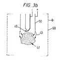
最初、図3aで概略図示するように、破砕サイト40に隣接する電場によって、破砕サイトへ供給された液の霧化が行われるので、帯電液滴のスプレーまたはジェット42をもたらす。ユーザーが息を吸い込むと、空気が開口部8を通って第2チャンバ3bに同伴されるとともに、孔明き遠方電極60を通って遠方電極60を境界とする破砕チャンバ内に導かれる。この孔明き電極60を通る空気の総合的な動きによって、帯電液滴その他の帯電破砕生成物が電極60に影響を与えるのを妨害または阻止する。放電電極50に加えられる電圧は、コロナ放電によって、第2チャンバ3b内の空気その他の気体分子の霧化をもたらし、液滴に対して反対に帯電したイオンを生じさせる。図3aに一点鎖線で概略図示するように、最初、反対に帯電した空気または気体イオンは液スプレー42から離れて、より負に帯電した(この場合はアースされている)遠方電極60の方向に誘引される。しかしながら、図3bに示すように、液滴スプレー42の発生によって生じた空間電荷は結局、イオンをそれらの正常通路から離れて液滴スプレー42の方向に誘引するのに充分な電荷となり、液滴上の電荷を、放電電極50によって生成された反対に帯電した空気または気体分子によって少なくとも部分的に放電させることができるので、ユーザーによって吸い込まれる液滴は、少なくとも部分的に放電されている。
【0038】
放電電極50によって破砕サイト40から隔てて配置された遠方電極60の使用によって、放電電極50を破砕サイト40の比較的近くに配置できるので、放電電極によって生成される気体イオンが破砕プロセスを妨げることがない。一般に、放電電極と破砕サイト間の距離は、放電電極と遠方電極間の距離の、例えば約2倍よりも大きくなるだろう。現実には、実際の相対距離は、電極50、60および破砕サイト40に加えられたそれぞれの電圧との組合せで選択されて、帯電液滴の充分な雲が発生するまで、気体イオンが確実に遠方電極60の方向に向けられて効率的な放電を保証するようにする。通常、放電電極50は破砕サイトに6〜12mm程近付けてよい。これによって、装置の構造が特にコンパクトにされて、破砕および放電装置は、例えば高さ約40mm、直径約30mmとなり、手持ちの使用と、ハンドバッグやユーザーのポケットに入れて持ち運ぶために特に適したものにすることができる。
【0039】
20容積%のポリエチレングリコールと80容積%のエタノールに通常は容積当たり2質量%のサルブトモールを含んだ液体配合物を使用し、破砕サイト40は、液を1.33μL/s(マイクロリットル/秒)の流量で供給するとともに−2.3kVの電位に保ち、破砕サイト40に中心を持つ直径15mmの円の円周まわりに90°間隔で配置した4個の放電電極50を+2kVに維持するとともに、接地した直径25mmの円筒形孔明き電極60を破砕サイトに対して同心に配置して、実験を行った。装置の出口4から出てきた液滴は実質的に帯電していなかったし、97%(破砕サイトに供給された薬の中で実際に装置の出口4に送出された質量の百分率)を超える装置効率が観察された。
【0040】
電気流体力学的破砕によって生成された帯電液滴は、帯電液滴の安定性に対するレイリー基準におおよそ対応する電荷対質量比を持つ、すなわち:
【0041】
放電電極構成は、放電電極に加えられる電圧を、破砕サイトに加えられた電圧ならびに破砕される液の抵抗率と流量に従って調節して、放電電極によって生成されるイオン化された空気分子の数が、破砕材料を完全または部分的に放電させるのに充分になるようにして、帯電液滴を完全または部分的に放電させるように構成してもよい。
【0042】
図4は、本発明を実施する投与装置の別の実施例の要部を示す、図2に類似した部分断面図である。
【0043】
図4に示す投与装置は、電圧源20、電圧発生器兼制御回路21、破砕サイト40、放電電極50、および遠方電極60を有し、図2に関して説明した対応コンポーネントと同様に構成されるとともに、スイッチSW1がユーザーによって上記のように操作されると、それらのコンポーネントと同様に作動する。
【0044】
図4に示す投与装置は、投与される液が破砕サイト40に供給される点で、図2に示す装置とは異なる。図4に示す構成では、投与される液は、可撓式バッグの形かまたはベローズ型の構成を持つ押し潰し式リザーバ45内に保持される。押し潰し式リザーバ45は出口パイプ46を持ち、パイプはポンプチャンバ32aの入口パイプ56内へ流体密に嵌められ、入口パイプは、破砕サイト40に液を供給するための供給チューブ33と共に、例えばモールドされて一体に形成してもよい。
【0045】
可撓膜57はポンプチャンバ32aの上部の開口部へ流体密に取り付けられる。可撓膜57の周辺部は、図示の構成では、開口部の境界となる双子フランジ55a、55b間に保持される。流体密を確実にするために、Oリングまたは類似シール58を設けてもよい。例えば、ポンプチャンバ32aがプラスチック材料からモールドされる別の構成では、可撓膜をモールド工程中に適切に位置決めしてもよい。
【0046】
可撓膜は、制御回路21によって膜制御部材59に加えられる電圧が所定の値に達すると、膜制御部材59の制御の下に湾曲される。膜制御部材59は、例えば、Bewdley Road, Stourport-on-Semern, Worcestershire DY13 7QR, UKにある Morgan Matroc Ltd. から市販されるような、金属板上にセラミックディスクによって形成される圧電素子でよいが、勿論、膜57を湾曲させる他の手段、例えば、ピストン装置や機械的または静電的に連結されたレバーシステムを使用してもよい。
【0047】
図4に示すように、破砕サイト40を提供する導電ロッド41は、ポンプチャンバ32aの内壁上に設けたピボットマウント62へ一端を枢着された支持アーム61へ枢着され、そこから垂下している。支持アーム61の他端は、可撓式リザーバ45からの出口パイプ46を閉じるためのバルブ部材35aを支えている。支持アーム61は支持バー63によってピボットマウント62に隣接して支持され、支持バー自体は、ポンプチャンバ32aのベース壁へ他端を固着された圧電素子64の一端に取り付けられる。この場合、圧電素子64は通常、ポンプチャンバ内の液から隔離するための薄い可撓性の抵抗性被覆を持つだろう。圧電素子64は所定の印加電圧に対して、単一の圧電セラミック層よりも大きな動きを与える複数のセラミック層から形成された圧電バイモルフから成ることが望ましい。このような圧電バイモルフも Morgan Matroc から市販されている。
【0048】
図4に示す投与装置の使用前は、圧電素子59と64のどちらにも電圧が印加されていない。この状態で、図5に示すように、導電ロッド41の自由端41aが絶縁供給パイプ33の縮径部分と協働して絶縁供給パイプの出口33aを閉じるバルブヘッドを形成することによって、蒸発による液損失を防止するようになっている。バルブヘッド35aは可撓リザーバ45の出口46から離れて配置されているので、ポンプチャンバ32aを液で充満することができる。
【0049】
スイッチSW1がユーザーによって作動されて、制御回路によって加えられる電圧が必要な値に達すると、圧電素子64が撓むか湾曲して、ロッド41を持ち上げることによってバルブヘッド35aがリザーバ45の出口パイプ46を閉じるとともに、ロッド41の自由端を供給パイプ33の出口33aから移動させて装置を図4で示す状態に導く。圧電素子59に加えられた電圧が所定の値に達すると、圧電素子59は膜57を図4の下方に湾曲させるので、ポンプチャンバ32a内の液を供給パイプ33の出口の方向へ定常流量で押し流す。電圧発生器兼制御回路21は、図2、3a、3bに関して説明した方法と同様の方法で破砕サイト40、放電電極50、および遠方電極60へ電圧を加えるので帯電液滴のスプレーをもたらし、帯電液滴は次に放電電極50によって放電されて、ユーザーが息を吸い込む作用で、装置の出口4を通ってユーザーの上気道に入る。上述のように、制御回路はマイクロプロセッサまたは抵抗・コンデンサRC回路網制御回路でよい。
【0050】
図6aは、本発明を実施する別の投与装置の要部の、図2と類似した部分断面図を示す。
【0051】
図6aに示す構成で、投与液は、液供給パイプ33へ液を導くための液案内漏斗装置48にその毛細管出口47aを連結された注入器47の中に入れられ、液供給パイプは、この実施例では、第1チャンバ3aを第2チャンバ3bから分割する壁6に取り付けられるか、それと一体に形成される。
【0052】
注入器本体47は空気抜き49aを備えたナット49に取り付けられる。図示しないが、ナット自体は、上部または第1チャンバ3aの壁に従来方法で固定される。注入ピストン47bは、ナット49を通ってそれと協働するねじ付きロッド70によって支持される。
【0053】
ねじ付きロッド70の他端は、従来形式の一方向継手71によって、電圧源20と制御回路21を装置の残りの部分から分離するハウジングの内部璧9に回転可能に取り付けられたシャフト72に連結される。平型コイルスプリング73は一端をシャフト72に固定されるとともに、他端をハウジングの内面に固定される。レバー74はシャフト72に固定されて、そこから延びる。レバーの自由端74aは、ハウジングに設けられたスロット75を通って延びるので、レバー74の自由端74aをユーザーが握ることができる。レバー74は、下記に説明するようにスロット75内で移動できるので、ユーザーはスプリング73を巻き上げることができる。
【0054】
カム面80は、付勢スプリング82の作用に抗して、ロッド41の一端41bをサポート81上に保持するので、ロッド41の他端41aを、液供給パイプ33の出口33aを閉じる位置に付勢する。
【0055】
カム面80は、外部回転式スリーブ85からハウジング3の開口部を通って延びるロッド83上に設けられる。
【0056】
第1チャンバ3aの側壁の一部を形成するハウジングの部分3cは、第2チャンバ3bを形成するハウジングの側璧を形成する部分3dに対して凹んでおり、その下端に、スリーブ85の軸方向に延びるリム85aを受けるリップ3fを備えた半径方向外方に延びるフランジ3eを持つ。
【0057】
スリーブ85の上端は、上部チャンバの頂部を形成するとともにスリーブの軸方向に延びる円周突起を受けるための凹部86aを有する独立のキャップ部材86によって適切に保持される。キャップ部材は、例えば接着剤によってハウジング部分3cに固定してもよい。
【0058】
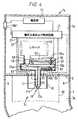
図6aに示す装置の操作を、図6aのVI-VI線に沿った図6aの装置の断面図を概略的に示す図6bによって説明する。簡単のために、図6bは、コイルスプリング73、スプリング73の一端が取り付けられシャフト72、レバー74、およびそれに関連する開口部75とストッパ76以外の、装置のすべてのコンポーネントを省略する。ユーザーはまず、レバー74を、そのスロット75内で図6bの矢印Aの方向にコイルスプリング73の付勢力に抗して回転させてコイルスプリングを巻き上げることによって装置の準備をする。一方向継手71は、スプリングが巻き上げられるときのピストンロッド70の回転を防止する。ストッパ76は開口部75内に取り付けられ、レバーがストッパに当たったときにレバーを係止するようになっている。例えば、ストッパ76は、レバーがストッパの上に乗るとレバーを係止するスプリング付勢式回り止めから成ってもよい。一旦、スプリングが巻き上げられると、ユーザーがスリーブ85を回すことによってカム面がロッド41の端部41bに対して動かされて、付勢スプリング82がロッド42を図6aの上方に動けるようにするので、液供給パイプ33の出口33aが開かれる。漏斗装置48に開口部を設けて、ロッド41が動けるようにする。
【0059】
ハウジングのキャップ86の頂部に設けたスイッチSW1の作動によって、上述のように、制御回路が電極41、50、60に必要電圧を供給するので、ユーザーは次にボタン(図示せず)を押して、回り止め76とレバー74間の係止を解放して、コイルスプリング73がピストンロッド70のねじ付きシャフトを一定角度にわたって一定速度で回転できるようにして、ピストンロッド70とナット49間の協働によってピストン47bを注入器47を通って移動させるので、計量された量の液が定常速度で注入器から液供給パイプ33へ供給される。ナット49の空気抜き49aによって空気が注入器に進入できるので、ピストン47bの動きが可能になる。
【0060】
供給パイプ33の出口33aから出てきた液は破砕サイト40の電場によって霧化または破砕されて、充分な空間電荷が蓄積されると、こうして生成された液滴上の電荷は、上記のように、放電電極50によって発生したイオンによって放電されるので放電液滴の雲またはスプレーが提供されて、それをユーザーが吸入できることになる。
【0061】
レバー74はスイッチSW1に機械的または/電気的に接続できるので、スイッチSW1を押すことによってもレバーが解放されてスプリング73がピストンを動かすことができ、従って、独立のボタンが必要でははくなる。
【0062】
一旦、投与量の液が供給パイプ33の出口33aから供給されると、ユーザーはスリーブ85を回転させ、液供給パイプ33の出口33aを閉じる位置までロッドを戻す。
【0063】
上記動作は、ユーザーが装置の使用を望む度毎に繰り返され、それぞれの使用にともなって、ピストン47bは注入器の下方に移動して、供給パイプ33に対して毎回、計量された投与量を送り出す。
【0064】
当然のことながら、コイルスプリングを巻き上げたりピストンを付勢することによって、計量された投与量を供給パイプ33に送出させる別の方法を使用してもよい。
【0065】
図7は、本発明を実施する装置の更なる実施例の要部の、図6aに類似した部分断面図である。
【0066】
図7に示す装置の操作は、液を供給パイプ33へ供給する方法を除いて、図6aに示すものと同一である。図7に示す装置で、注入器47は往復式ピストン47bを持つ。ピストンロッド70aの自由端は、スプリング73aの付勢作用に抗してスプリング付勢ラッチ78によって第1位置に保持される支持プレート77に取り付けられる。ラッチ78はハウジング3へ枢着され、ハウジング3の開口部を通して延びてユーザー操作式スイッチを形成する部分78aを持つので、回転式スリーブ85を回転させて出口33aを開いてスイッチSW1を作動させた後、ユーザーが部分78aの上を下方に押すと、ラッチ78は支持プレート77のエッジを通り越して上方へ枢動するので支持プレートを解放して、プレート77が支持部材79に当たるまで、支持プレートがスプリング73aの作用によって下方に移動できるようになる。これによって、ピストンは、計量された投与量の液を出口33aへ供給して、そこで液が上述のように電気流体力学的に破砕される。供給される実際の投与量は、支持部材79の位置によって決まる。
【0067】
支持部材79は、ハウジング3の壁に画成されたスライドウェイ79aに摺動可能に取り付けられ、装置の再準備のために、ユーザーは支持部材79の自由端79bを握ってそれをスライドウェイ79a内で上方に動かすことによって、支持プレート77を図7で上方に動かしてラッチ78をそのスプリング付勢に抗して上方へ枢動させるので、支持プレート77が図7に示すようにラッチ78の上に載置されることになる。この戻りの動作時に、注入器内の液は、図4に示すものと類似のタイプの押し潰し式リザーバ45から一方向バルブ(図示せず)を通した供給によって補給される。
【0068】
言うまでもなく、任意の形式の付勢機構とラッチ機構を使って、図7に示す装置のピストンの動きを制御できる。更に、図6に示す装置を変更して、一方向継手を取り除いて押し潰し式リザーバ45を設けることによって往復ピストン構成を提供するようにしてもよい。
【0069】
当然のことながら、他の機械的レバー装置を使って、液供給バルブの開放と、ピストンロッドを回転させるためのスプリング機構の準備と解放を制御してもよい。また、機械的に連結されるか、静電的に連結されたレバーシステムを使用してもよい。
【0070】
電気的および機械的に作動される装置の組合せを使用してもよく、例えば、図6aと7に示すタイプの機械式出口バルブを電気作動の出口バルブと組合せて使用してもよいし、その他に、電気式ポンプ装置を機械式出口バルブと共に使用してもよい。
【0071】
図2、4、6a、7に示す構成では、破砕サイトは、液供給パイプ33を通って延びるとともに液供給パイプと協働することによって、液供給パイプからの液の供給を必要としないときに液供給パイプ開口部33aを閉じるバルブを形成するロッド41を備えている。
【0072】
ロッド41の端部41aと液供給パイプ33の開口部33aとは、バルブが閉じたときにその液密性を改良するように形成してもよい。例えば、図8に示すように、ロッド41は円錐形、すなわち鋭くするか尖った端部41aを備え、液供給パイプの開口部33aは、円錐台形で外に向かって狭くなるように構成して、バルブを閉じるときにロッドの円錐端または先端41aが液供給パイプの出口開口部内に延びるようにしてもよい。
【0073】
図9は更に別の構成を示し、ロッド41は、バルブを閉じるときに、液供給パイプの出口の協働面33c上に着座する半径方向に延びるフランジ41cを備えている。
【0074】
図10は、図2、6a、7に示す装置で使用できる更なる可能な構成を示し、ロッド41は、液供給パイプ33の開口部33aによって設けられた円錐台形バルブシート33dと協働する円錐形バルブヘッド41dを備えている。この構成では、ロッド41を持ち上げてバルブを閉じ、それを下に降ろしてバルブを開くようになっているので、図6aまたは7に示す付勢スプリング82上のカム面80の操作を逆にしなければならないだろう。
【0075】
上記の各構成で、破砕サイトは円筒形ロッド41によって点として設けられる。しかしながら、例えば、WO95/26235、 WO95/26234、または WO95/32807 に記載される他の形式の破砕サイトを使用してもよい。一実施例として、破砕サイトを、それぞれが WO95/32807 の図5に関して記載された図1に示すものに類似の、間隔をあけた複数の破砕点のリングまたは環として設けてもよい。別の可能性として、図11に概略図示するように、破砕サイト40を、使用時にそれに沿って多数のジェットが形成されるナイフエッジの形の破砕サイトを下端に設けた平面部材410で上述のロッド41を置換することによって、点や一連の点ではなくて、線として設けてもよい。別の可能性として、ロッド41の代わりに中空円筒を設けることで環状破砕サイトを使用してもよい。
【0076】
破砕サイト自体が回転対称の場合、例えば、破砕サイトがロッドまたは円筒から成る場合は、放電電極や電極および遠方電極は回転対称で、破砕サイトに対して同心に配列されること望ましい。しかしながら、破砕サイトが図11に示すように線形エッジとして設けられる場合は、放電電極は図12に示すように2つの長寸エッジ50aとして同様に設けられ、遠方電極は、使用時に発生電場が確実に破砕サイトと対称になるように、破砕サイトの両側に配置された2つの孔明き平面部材60aを備えてもよい。
【0077】
上述のように、放電電極は単一の放電点として形成されてもよいし、例えば、独立の放電針を備えた多数の離散放電点によって形成されてもよいし、また、図13に概略図示するような導電性抑制体50cによって適切に保持された放電ワイヤ50bを備えてもよい。
【0078】
上述の各構成で、液は重力送りか、可撓膜または注入ポンプなどのポンプ供給機構によって破砕サイトへ供給される。上述のように、他のポンプ供給機構の使用も可能で、例えば、EP-A-0029301 に記載されるような電気流体力学的ポンプや WO94/12285 の図6、7に関して記載されるような電気浸透ポンプを使用するか、あるいは、計量投与量を供給できる他の形式のポンプを使用してもよい。
【0079】
リザーバが押し潰し式か、あるいは可動壁を持つ実施の形態において、ポンプ供給作用は圧力システムによって提供される。圧力システムは、例えば、スプリング式圧力システムであって、スプリングがリザーバへ実質的に一定の圧力を加えてリザーバを実質的に一定速度で収縮させるようなシステムでよい。別の実施例では、圧力システムはいわゆるバリヤパックシステムであって、加圧された気体容器内にリザーバが配置されることによってその気体が圧力を加え、リザーバを押し潰すか可動壁を動かしてリザーバを収縮させるようにしたシステムでもよい。そのような圧力システムを使用する場合、通常は漏れを防ぐために液出口にバルブが必要となる。
【0080】
上述の各実施例では、遠方電極60は孔明けされて、ハウジングの内壁から間隔をあけて配置されているので、遠方電極を通る空気流によって破砕材料や生成物の遠方電極に対する影響を防止できるようになっている。しかしながら、導電性または半導電性被覆をハウジングの内壁上に設けることによって遠方電極を用意するとともにその被覆の上の空気流によって遠方電極に対する破砕生成物の影響を防止することは可能だろう。そのような構成では、ハウジングの内壁の少なくとも大部分が被覆されて接地されるので、特に効率的な電磁シールドが当然可能になるだろうが、その犠牲として、遠方電極への破砕生成物の堆積の可能性が増すので、破砕生成物の送出効率の低下を招くだろう。
【0081】
本発明を実施する装置によって送出される投与量は調節可能にできる。例えば、図2、4に示す装置では、図2のバルブ34、35および図4のバルブ35a、41aが開いている相対時間を使って、破砕サイトに送出される液量を制御してもよい。これは、例えば、制御回路の適切な調節によってバルブを作動させるためにそれぞれの電圧を必要電圧まで上昇させる速度を調節することによって達成できる。このような調節は、昇圧回路(ramp circuit)の抵抗とコンデンサの値を調節することによって工場レベルで実施できるし、電圧上昇速度を調節するために追加の抵抗とコンデンサの接続を切り換えるための切換え手段を設けて、薬剤師やエンドユーザーによって制御できるようにしてもよい。
【0082】
図6aと6bに示す装置では、スプリングが巻き上げられるか巻き戻しできる量、従って、ピストンが注入円筒内で移動する量は、スロット75の円周方向の範囲および/またはストッパ(abutment)76の位置を決定することによって選択できる。ストッパ76の位置は、特定患者の特定要球に対して装置を適合させるように薬剤師または医師によって選択できるようにしてもよいし、患者が必要な投与回数を選択できるように、患者が選択できるようにしてもよい。例えば、スロット75は、いくつもの異なる離散位置を備え、その位置にストッパ76を移動すると、各位置が、ハウジング上のスケールによって、基本投与量の所定の倍数を与えるものとして確認されるようにしてもよい。ストッパ76の位置と、従って投与量が薬剤師または医師によって選択できる場合、ストッパを、一旦スロット内に挿入すると適所に固定されるように設計してもよいし、また例えば、装置が送出することになっている投与量を容易に確認できるようにカラーコーディングしてもよい。
【0083】
図7に示す装置では、送出投与量は、例えば、スライドウェイ79aの長さを工場で調節することにより、または、上述のように配置された図6bで示すストッパ76に類似するストッパをスライドウェイに設けて調節してもよい。
【0084】
破砕サイトに送出される液の投与量を制御できることによって、装置を様々な患者の要求に適合させることができる。かくして、例えば、装置を大人や子供による使用に適合させることができるし、異なる液の投与量を必要とする様々な薬に対する使用にも適合させることができる。
【0085】
上述の実施例では、遠方電極60に加えられる電圧は、破砕サイト40と放電電極50に加えられる電圧の中間になるように構成されている。これは、3つの電極の中の一つがアースすなわち接地電位にある場合は2つの基準電圧が必要となる。図14は、上記の装置のいずれにも適用できる修正案を概略的に示す。図14に示す構成では、放電電極または電極(複数)50は、破砕サイト40に加わる電位に対して負となる電位HV−に連結される。図示の実施例では、破砕サイト40はアースされて(接地電位)、遠方電極60は抵抗Rを介してアースに連結される。通常、約−6kVの電圧を放電電極(単数、複数)50に加えてもよいし、抵抗Rは約600MΩでよい。
【0086】
負電圧HV−が最初に加えられると、放電電極(単数、複数)50によって生じたイオンは直ちに遠方電極60の方向に移動する。遠方電極またはケージ60自体は抵抗Rを通して放電するので遠方電極と放電電極50間の電位差を低下させ、それによって放電電極50によるイオンの生成が制限される。遠方電極60での電位が変化するにつれて、破砕サイト40と遠方電極間の電位差が増加して、破砕サイト40に供給される液の破砕を引き起こす。
【0087】
システムは自己平衡型である。遠方電極60の電位が放電電極50からのイオンの流れを調節するばかりでなく、破砕サイトから発生する帯電破砕物質によって生成される空間電荷も、必要に応じてイオンの発生を増加させることができる。
【0088】
装置の寸法が上記のような場合、放電電極(単数、複数)は−6kVで、抵抗Rはおおよそ600MΩ、遠方電極を通る電流はおおよそ5μAであり、従って、ケージまたは遠方電極60が到達する電位は、理想的な約3kVとなるだろう。
【0089】
図14に示す構成では、負のイオン/電子を用いて、破砕サイト40で生じる正に帯電した破砕物質を放電させる。これは急速な応答を可能にするとともに、システムを急速に平衡状態に到達させる。しかしながら、図14に示す構成を修正して、負の高圧電源HV−の代わりに正の高圧電源を使用することにより、また、抵抗Rを減らして、放電手段として正イオンが用いられた場合にそれらの生成が間接的であり、それは放電電極での電子放出によるのでなく電極への雪崩効果によるという事実を補償することによって、正イオンと協働するようにしてもよい。
【0090】
通常102 から108 Ω−mまでの範囲の抵抗率と1から250cpまでの範囲の粘性を持つ液が、本発明を実施する装置によって破砕できる。液を破砕サイトまで適切な流量で流すことが可能であれば、液は溶融物、溶液、懸濁液、乳濁液、マイクロサスペンション、マイクロエマルジョン、またはゲルでもよい。
【0091】
生成される破砕液滴のサイズは、与えられた液に対して、破砕させるために用いられる電場と流量とに依存する。上記の実施例では、破砕させるために使用される電場と破砕される液の流量は、上気道への送出に適したサイズの液滴を生成するように選択される。しかしながら、与えられた液に対して流量と電場を適切に選択することによって、口腔と喉部や鼻道、更には肺の小さな気管支への送出に適したサイズの液滴を提供できる。
【0092】
上述のように、本発明を実施する投与装置は主として、呼吸器系に薬剤を供給するための吸入器としての使用に適した、手持ちのポータブル装置としての使用を意図するものである。本発明を実施する装置による送出に適した薬剤は、上述の気管支拡張剤やステロイド剤、ならびに鼻粘膜の疾患および花粉症に伴う上気道の充血と疾患を含む上気道の疾患の治療用のその他薬剤を含む。
【0093】
鼻充血除去剤として使用される特定の薬剤は、オキシメタゾリン(oxymetazoline) 、キシロメタゾリン(xylometazoline)、フェニレフリン(phenylephrine) 、プロピルヘキサドリン(propylhexadrine) 、ネファゾリン(nephazoline) 、テトラハイドロゾリン(tetrahydrozoline)、および塩酸塩などのそれらの適当な塩、ならびにそれらの配合物を含む。
【0094】
本発明を実施する装置は、トリプタン類(triptans)(例えば、almotriptan 、eletriptan、 naratriptan、 rizatriptan、 sumatriptan、および zolmitriptan )や Pfizer によって作られたCP−122、288および E. Lilley が製造する Lanepitant などの抗偏頭痛薬として目下テスト中の薬の口または鼻供給に対しても好適だろう。本発明を実施する装置は、例えば、薬剤の随時供給用のポケットサイズの手持ち吸入器としての使用に適しているが、その理由は、その設計によって、放電手段と破砕サイトとが、それらの機能を妨げることなく互いに接近できるようになるので、装置をコンパクトにできるからである。装置はまた、特に未熟なユーザーや虚弱者にとってその操作が簡単なのでユーザーに優しいに違いない。というのは、液滴スプレーはユーザーの呼吸の制御の下に送出されて、従来の噴霧システムのようにガス排出の力によるものではないからである。
【0095】
しかしながら、本発明を実施する装置はまた、他の液の液滴の投与のために、嗅覚影響物質、例えば、香りや香水、昆虫忌避剤や誘引剤、殺生物剤や殺虫剤、農薬その他の空中散布製品などの嗅覚抑制剤や嗅覚刺激剤を投与するための、例えば、デスクトップまたは手持ち式ディスペンサーとして使用してもよい。
【図面の簡単な説明】
【図1】 図1は、本発明を吸入器として実施する投与装置を使用する人物を示す線図である。
【図2】 図2は、本発明を実施する投与装置の一実施例による部分断面図を示し、該投与装置の機能部品の概略ブロック図である。
【図3a】 図3aと3bは、本発明による投与装置の使用時の、帯電破砕材料の生成とその材料のその後の放電とを示す概略線図である。
【図3b】 図3aと3bは、本発明による投与装置の使用時の、帯電破砕材料の生成とその材料のその後の放電とを示す概略線図である。
【図4】 図4は、本発明を実施する投与装置の別の実施例の要部による、図2に類似した部分断面図を示す。
【図5】 図5は、図4に示す投与装置の要部の部分断面図を示し、その操作の説明図である。
【図6a】 図6aは、本発明を実施する投与装置の別の実施例の要部の、図2に類似した部分断面図を示す。
【図6b】 図6bは、図6aに示す装置の部分の操作を示すための概略線図である。
【図7】 図7は、本発明を実施する投与装置の別の実施例の要部の、図6aに類似した部分断面図を示す。
【図8】 図8〜11は、本発明を実施する投与装置での使用に適した破砕サイトの各種形式を線図で示す。
【図9】 図8〜11は、本発明を実施する投与装置での使用に適した破砕サイトの各種形式を線図で示す。
【図10】 図8〜11は、本発明を実施する投与装置での使用に適した破砕サイトの各種形式を線図で示す。
【図11】 図8〜11は、本発明を実施する投与装置での使用に適した破砕サイトの各種形式を線図で示す。
【図12】 図12は、本発明を実施する投与装置に適した破砕サイトと、放電および遠方電極のための一つの可能な配置または構成を示す。
【図13】 図13は、本発明を実施する投与装置で使用される破砕サイトと、放電および遠方電極のための別の可能な構成を示す。
【図14】 図14は、本発明を実施する装置のための更なる変更を、図3aに類似した線図によって示す。[0001]
TECHNICAL FIELD OF THE INVENTION
The present invention relates to an administration device and method for administering crushed material to, but not limited to, the respiratory system of animals, particularly mammals and birds.
[0002]
[Background Art and Problems to be Solved by the Invention]
For example, as described in GB-A-1569707, when the liquid coming out from the outlet hits the electric field, the net charge in the liquid cancels the surface tension of the liquid when it appears in free space, Dosing devices are known that produce monodisperse sprays or clouds of droplets by the process by which the resulting repulsive force results in electrohydrodynamic cones and jets that break up to form droplets. This process is commonly referred to as electrohydrodynamic crushing. The device described in GB-A-1569707 was designed primarily for grain spraying and is portable but inherently a large device. Droplets made with this device are charged close to their Layleigh Limit, so when used, they move rapidly toward a wet conductive surface. Thus, such devices are considered unsuitable for delivery of droplets to the animal's respiratory system, although the charge on the droplets conducts moist conductive in the mouth rather than passing the droplets through the upper respiratory tract. This is because it is considered to move rapidly in the direction of the sex surface.
[0003]
GB-A-2018627 is an electrohydrodynamic spray device in which the charged droplet spray generated at the crushing site is completely discharged by a discharge electrode in the shape of a sharp or pointed blade placed downstream of the crushing site. Or a device that is partially discharged is described. Therefore, when this apparatus is operated, the discharge electrode generates gas ions due to corona discharge by the potential applied to the discharge electrode. The gaseous ions are then attracted to the oppositely charged droplets of the spray produced by the crushing site, causing the droplets to be fully or at least partially discharged. Thus, GB-A-2018627 results in at least partial discharge of droplets by ion bombarding.
[0004]
Unfortunately, ion bombarding discharges can interfere with the shredding process and reduce the quality and reliability of the droplet spray. In fact, an undesirable effect of ion bombarding on the crushed spray was observed in research experiments. In order to counteract these undesirable effects, EP-A-0234842 proposes the use of an annular shield electrode placed between the crushing site and the discharge electrode to maintain a steady electric field at the crushing site and The aim is to shield the resulting droplet spray from ions made at the discharge electrode downstream of the crushing jet or spray. The central opening of the shield electrode must, of course, be large enough to allow free passage of the charged droplets, but the ions do not move around the spray cloud and interfere with the electrohydrodynamic cone or jet. It must be small enough to However, experiments show that using a liquid formulation that is compatible with human physiology, such as water, ethanol, polyethylene glycol, etc., the opening of the shield electrode must be very large, It cannot efficiently block the passage of ions as required.
[0005]
An electrohydrodynamic droplet dispensing device of the kind described in EP-A-0234842 is described in “Micron-sized droplets from tailor cones” published on pages 37-49 of Journal of Aerosol Science 23 (1992) by Meesters et al. It is described in a paper entitled “Generation of Micron Sized Droplets from the Taylor Cone”. The device described in that paper is relatively large, on the order of about 150 mm in height and 50 mm in diameter. Experiments have shown that reducing the size of the device causes significant stability problems. For example, if the current from the discharge electrode is in the same order as the current generated by the charged droplet spray, the droplet will inevitably have a very large impact on the tip of the discharge electrode and reduce the ionic current, resulting in This leads to further droplet denseness. Such problems may be overcome by increasing the ionic current relative to the electron flow produced by the electrohydrodynamic spray, but the ions resulting from the entrainment of air by the rapidly moving ions generated by the discharge electrode The wind causes excessive air turbulence in the device, and an unacceptably large percentage of the droplets can affect the inner surface of the device or interfere with the electrohydrodynamic cone or jet of the droplet spray and Will stabilize and reduce the monodispersity of the spray.
[0006]
Summary of the Invention
According to one aspect of the present invention, an administration device that is particularly suitable for use to deliver a crushed material, such as a droplet, to the respiratory system of an animal, such as a human, from a liquid supplied to the crushing means By crushing means for generating an electric field sufficient to generate a charged crushing material, and discharging means for discharging the crushing material at least partially, and by providing an ion passage not including the crushing means, crushing An apparatus is provided that prevents ions generated by the discharge means from moving to the crushing means until there is accumulation of space charge due to the generation of the charged crushing material spray by the means.
[0007]
In another aspect, the present invention provides that when a charged spray of crushed material is generated by the electrohydrodynamic crushed material, the resulting space charge is removed from the path away from the crushing means for ions of opposite charge to the crushed material. A dosing device is provided having a geometry such that the ions at least partially discharge the spray by being deflected and directed again towards the crushing means.
[0008]
In another aspect, the present invention provides a permeable, electrically conductive or semiconductive inner wall that draws air into the crush area when the crush material is aspirated from the device, thereby providing An administration device is provided that can reduce the effect and increase the amount of crushed material inhaled by the user.
[0009]
In another aspect, the present invention is a flexible or flexible device that increases the useful life of the device by preventing contact between water and the fluid being administered and acting, for example, to retard evaporation of the solvent during storage. An electrohydrodynamic administration device with a crushable fluid reservoir is provided.
[0010]
In another aspect, the present invention provides a dosing device that uses a piezoelectric diaphragm pump coupled to an electrical control circuit to provide a steady flow of fluid to the electrohydrodynamic disruption means.
[0011]
In another aspect, the present invention provides a dosing device wherein valve means are provided at the electrohydrodynamic disruption site to prevent liquid evaporation when the device is not in use. The valve means can be actuated, for example, by a piezoelectric element and / or a mechanically or electrostatically coupled lever system.
[0012]
In another aspect, the present invention provides a dosing device having means for pumping liquid to electrohydrodynamic disruption means. The pump supply means can be, for example, in the form of an electrohydrodynamic injector having a user-operated piston on which a steady mechanical force provided by a spring biasing means acts, or for example as described in EP-A-0029301 It may be in the form of a hydrodynamic pump or an electroosmotic pump as described in WO94 / 12285.
[0013]
In embodiments where the reservoir is collapsible or has a movable wall, the pumping action may be provided by means of a pressure system. The pressure system may be, for example, a spring pressure system where the spring applies a substantially constant pressure to the reservoir or its movable wall to cause the reservoir to contract at a substantially constant rate. In another embodiment, the pressure system has placed the reservoir in a pressurized gas container so that the gas can apply pressure to collapse the reservoir or move the movable wall to contract the reservoir. A barrier pack system may be used. When using such a pressure system, a valve is usually required at the liquid outlet to prevent leakage.
[0014]
In another aspect, the present invention is an administration device configured to generate crushed material by electrohydrodynamic crushing of a liquid supplied to an electrohydrodynamic crushing means, the crush generated during operation In order to control the amount or dose of the material, a dosing device is provided which is provided with means for controlling the flow of liquid to the crushing site, for example the volume of liquid and the rate at which it is supplied.
[0015]
In another aspect, the invention relates to an electrohydrodynamic crushing means and an electromagnetic high voltage multiplier of the type manufactured by Brandenburg or Start Spellman or a piezoelectric high voltage as described, for example, in WO94 / 12285 An administration device is provided having means for supplying voltage to the discharge means in the form of a power supply.
[0016]
The present invention also allows liquid to be supplied to the electrohydrodynamic crushing means prior to operation of the crushing means and from the discharge means for a predetermined time until a cloud of charged crushing material is generated by the crushing means. An administration device is provided having a control means for delaying the production of ions.
[0017]
Depending on the particular liquid, flow rate, and applied electric field, the liquid solidifies or gels before and after crushing, begins to solidify or gel, or remains liquid. When the liquid is solidified or gelled before crushing, it becomes a single fiber or a short-length fiber (fibril). If the device is not intended for use as an inhaler, the term shredding will of course be considered to include the formation of fibers and fibrils and said gel or droplets. If the device is an inhaler, the fragmentation can be droplets, solid droplets or gel droplets, or fibrils.
[0018]
The present invention also provides an inhaler having any one or more features of the aforementioned aspects.
[0019]
The present invention also provides a method of delivering a medicament to the respiratory system of an animal, such as a mammal or a bird, using a device having any one or more features of the aforementioned aspects.
[0020]
The invention also comprises olfactory agents, such as scents, perfumes, insecticides, biocides, pesticides, or inhibitors, insect attractants or insecticides or other aerial spray products or stimulants. An administration device for delivering electrohydrodynamic fracture material is provided.
[0021]
DETAILED DESCRIPTION OF THE INVENTION
Embodiments of the present invention will now be described by way of example with reference to the accompanying drawings.
[0022]
As schematically illustrated in FIG. 1, an
[0023]
The
[0024]
FIG. 2 shows a partial cross-sectional view of an embodiment of an administration device embodying the present invention.
[0025]
As shown in FIG. 2, the
[0026]
The
[0027]
The
[0028]
The crushing
[0029]
The
[0030]
The far electrode 60 is disposed so as to be separated from the crushing
[0031]
The far electrode 60 comprises a perforated conductor or semiconductor, which is effective when the wall of the
[0032]
The crushing
[0033]
The
[0034]
If desired, a
[0035]
In the configuration shown in FIG. 2, the
[0036]
In order to use the administration device shown in FIG. 2 as an inhaler, the user 2 puts the mask on the nose and mouth, grasps the
[0037]
Initially, as schematically illustrated in FIG. 3a, the electric field adjacent to the crushing
[0038]
By using the
[0039]
A liquid formulation containing 20% by volume polyethylene glycol and 80% by volume ethanol, usually containing 2% by weight salbutomol per volume, was used, and the crushing
[0040]
Charged droplets produced by electrohydrodynamic fragmentation have a charge-to-mass ratio approximately corresponding to the Rayleigh criterion for charged droplet stability, ie:
[0041]
The discharge electrode configuration adjusts the voltage applied to the discharge electrode according to the voltage applied to the crushing site as well as the resistivity and flow rate of the liquid to be crushed so that the number of ionized air molecules produced by the discharge electrode is It may be configured to fully or partially discharge charged droplets so that the crushed material is sufficient to fully or partially discharge.
[0042]
FIG. 4 is a partial cross-sectional view similar to FIG. 2, showing the main part of another embodiment of the administration device embodying the present invention.
[0043]
The dosing device shown in FIG. 4 has a
[0044]
The administration device shown in FIG. 4 differs from the device shown in FIG. 2 in that the liquid to be administered is supplied to the crushing
[0045]
The
[0046]
The flexible membrane is bent under the control of the
[0047]
As shown in FIG. 4, the
[0048]
Prior to use of the administration device shown in FIG. 4, no voltage is applied to either of the
[0049]
When the switch SW1 is actuated by the user and the voltage applied by the control circuit reaches the required value, the
[0050]
FIG. 6a shows a partial cross-sectional view similar to FIG. 2 of the main part of another administration device embodying the present invention.
[0051]
In the configuration shown in FIG. 6a, the administration liquid is placed in a
[0052]
The
[0053]
The other end of the threaded
[0054]
Since the
[0055]
The
[0056]
A
[0057]
The upper end of the
[0058]
The operation of the device shown in FIG. 6a is illustrated by FIG. 6b, which schematically shows a cross-sectional view of the device of FIG. 6a along the line VI-VI of FIG. 6a. For simplicity, FIG. 6 b omits all components of the device except the
[0059]
The operation of the switch SW1 provided on the top of the
[0060]
When the liquid coming out from the
[0061]
Since the
[0062]
Once a dose of liquid is supplied from the
[0063]
The above operation is repeated each time the user desires to use the device, and with each use, the
[0064]
Of course, other methods of delivering a metered dose to the
[0065]
FIG. 7 is a partial cross-sectional view similar to FIG. 6a of the main part of a further embodiment of the apparatus embodying the present invention.
[0066]
The operation of the apparatus shown in FIG. 7 is the same as that shown in FIG. 6 a except for the method of supplying the liquid to the
[0067]
The
[0068]
Needless to say, any type of biasing mechanism and latch mechanism can be used to control the movement of the piston of the apparatus shown in FIG. Further, the apparatus shown in FIG. 6 may be modified to provide a reciprocating piston configuration by removing the one-way joint and providing a
[0069]
Of course, other mechanical lever devices may be used to control the opening of the fluid supply valve and the preparation and release of the spring mechanism for rotating the piston rod. Alternatively, a mechanically coupled or electrostatically coupled lever system may be used.
[0070]
A combination of electrically and mechanically actuated devices may be used, for example, a mechanical outlet valve of the type shown in FIGS. 6a and 7 may be used in combination with an electrically operated outlet valve, etc. In addition, an electric pump device may be used with a mechanical outlet valve.
[0071]
In the configuration shown in FIGS. 2, 4, 6a and 7, the crushing site extends through the
[0072]
The
[0073]
FIG. 9 shows yet another configuration, in which the
[0074]
FIG. 10 shows a further possible configuration that can be used in the device shown in FIGS. 2, 6a, 7 wherein the
[0075]
In each of the above configurations, the crushing site is provided as a point by the
[0076]
When the crushing site itself is rotationally symmetric, for example, when the crushing site is composed of a rod or a cylinder, the discharge electrode, the electrode, and the far electrode are preferably rotationally symmetric and arranged concentrically with respect to the crushing site. However, when the crushing site is provided as a linear edge as shown in FIG. 11, the discharge electrode is similarly provided as two
[0077]
As described above, the discharge electrode may be formed as a single discharge point, for example, may be formed by a number of discrete discharge points with independent discharge needles, and is schematically illustrated in FIG. You may provide the discharge wire 50b appropriately hold | maintained by the
[0078]
In each configuration described above, the liquid is fed to the crushing site by gravity feed or by a pump feed mechanism such as a flexible membrane or an infusion pump. As mentioned above, other pump supply mechanisms can be used, for example, electrohydrodynamic pumps as described in EP-A-0029301 or electric fluids as described with respect to FIGS. 6 and 7 of WO94 / 12285. Osmotic pumps may be used, or other types of pumps capable of delivering metered doses.
[0079]
In embodiments where the reservoir is collapsible or has a movable wall, the pumping action is provided by a pressure system. The pressure system may be, for example, a spring-type pressure system, where the spring applies a substantially constant pressure to the reservoir, causing the reservoir to contract at a substantially constant rate. In another embodiment, the pressure system is a so-called barrier pack system, where the reservoir is placed in a pressurized gas container so that the gas applies pressure and either crushes the reservoir or moves the movable wall to move the reservoir. It is also possible to use a system that contracts. When using such a pressure system, a valve is usually required at the liquid outlet to prevent leakage.
[0080]
In each of the above-described embodiments, the
[0081]
The dose delivered by the device embodying the present invention can be adjustable. For example, in the apparatus shown in FIGS. 2 and 4, the amount of liquid delivered to the crushing site may be controlled using the relative time that the
[0082]
In the device shown in FIGS. 6a and 6b, the amount by which the spring can be wound or unwound, and thus the amount by which the piston moves in the injection cylinder, depends on the circumferential extent of the
[0083]
In the apparatus shown in FIG. 7, the delivery dose can be adjusted, for example, by adjusting the length of the
[0084]
The ability to control the dose of liquid delivered to the crushing site allows the device to be adapted to different patient requirements. Thus, for example, the device can be adapted for use by adults and children, and can be adapted for use with a variety of drugs that require different fluid dosages.
[0085]
In the above-described embodiment, the voltage applied to the
[0086]
When the negative voltage HV− is first applied, the ions generated by the discharge electrode (s) 50 immediately move in the direction of the
[0087]
The system is self-balancing. The potential of the
[0088]
When the dimensions of the device are as described above, the discharge electrode (s) is −6 kV, the resistance R is approximately 600 MΩ, the current through the far electrode is approximately 5 μA, and therefore the potential reached by the cage or
[0089]
In the configuration shown in FIG. 14, the negatively charged ions / electrons are used to discharge the positively charged crushed material generated at the crushing
[0090]
A liquid having a resistivity in the range of 10 @ 2 to 10 @ 8 .OMEGA.-m and a viscosity in the range of 1 to 250 cp can be crushed by the apparatus embodying the present invention. The liquid may be a melt, a solution, a suspension, an emulsion, a microsuspension, a microemulsion, or a gel, as long as the liquid can be flowed to the crushing site at an appropriate flow rate.
[0091]
The size of the crushed droplets generated depends on the electric field and flow rate used to break up for a given liquid. In the above example, the electric field used to disrupt and the flow rate of the fluid to be disrupted are selected to produce droplets of a size suitable for delivery to the upper airway. However, by appropriately selecting the flow rate and electric field for a given fluid, droplets of a size suitable for delivery to the oral cavity and throat, nasal passages and even to the small bronchi of the lungs can be provided.
[0092]
As mentioned above, the administration device embodying the present invention is primarily intended for use as a handheld portable device suitable for use as an inhaler for delivering medication to the respiratory system. Agents suitable for delivery by devices embodying the present invention include the bronchodilators and steroids described above, and others for the treatment of upper respiratory tract diseases including upper airway hyperemia and disease associated with nasal mucosal diseases and hay fever. Contains drugs.
[0093]
Specific drugs used as nasal decongestants are oxymetazoline, xylometazoline, phenylephrine, propylhexadrine, nephazoline, tetrahydrozoline, and Including their appropriate salts, such as hydrochloride salts, as well as blends thereof.
[0094]
Devices implementing the present invention include triptans (eg, almotriptan, eletriptan, naratriptan, rizatriptan, sumatriptan, and zolmitriptan), CP-122 made by Pfizer, and Lanepitant manufactured by E. Lilley. It may also be suitable for oral or nasal supply of drugs currently being tested as anti-migraine drugs. The device embodying the present invention is suitable for use, for example, as a pocket-sized hand-held inhaler for the occasional delivery of drugs, because, depending on its design, the discharge means and the crushing site function their function. This is because the apparatus can be made compact because they can approach each other without interfering with each other. The device must also be user-friendly as it is easy to operate, especially for inexperienced users and the weak. This is because the droplet spray is delivered under the control of the user's breath and is not due to the power of outgassing as in conventional spray systems.
[0095]
However, the device embodying the present invention may also be used for the administration of other liquid droplets, such as olfactory influence substances such as scents and perfumes, insect repellents and attractants, biocides and insecticides, pesticides and other For example, it may be used as a desktop or hand-held dispenser for administering olfactory depressants and olfactory stimulants such as airborne products.
[Brief description of the drawings]
FIG. 1 is a diagram showing a person using a dosing device implementing the present invention as an inhaler.
FIG. 2 shows a partial cross-sectional view of one embodiment of an administration device embodying the present invention and is a schematic block diagram of the functional components of the administration device.
Figures 3a and 3b are schematic diagrams showing the production of a charged fractured material and the subsequent discharge of the material when using an administration device according to the invention.
Figures 3a and 3b are schematic diagrams showing the production of a charged fracture material and the subsequent discharge of the material when using the administration device according to the invention.
FIG. 4 shows a partial cross-sectional view similar to FIG. 2, according to the main part of another embodiment of the administration device embodying the present invention.
FIG. 5 is a partial cross-sectional view of the main part of the administration device shown in FIG. 4 and is an explanatory view of the operation thereof.
FIG. 6a shows a partial cross-sectional view similar to FIG. 2 of the main part of another embodiment of the administration device embodying the present invention.
6b is a schematic diagram for illustrating the operation of the part of the apparatus shown in FIG. 6a.
FIG. 7 shows a partial cross-sectional view similar to FIG. 6a of the main part of another embodiment of the administration device embodying the present invention.
FIGS. 8-11 illustrate diagrammatically various types of crushing sites suitable for use in a dosing device embodying the present invention.
FIGS. 8-11 show diagrammatically various types of crushing sites suitable for use in a dosing device embodying the present invention.
FIGS. 8-11 show diagrammatically various types of crushing sites suitable for use in a dosing device embodying the present invention.
FIGS. 8-11 show diagrammatically various types of crushing sites suitable for use in a dosing device embodying the present invention.
FIG. 12 shows a fracture site suitable for a dosing device implementing the present invention and one possible arrangement or configuration for the discharge and remote electrodes.
FIG. 13 shows another possible configuration for the crushing site and discharge and remote electrodes used in the dosing device embodying the present invention.
FIG. 14 shows a further modification for an apparatus implementing the invention by a diagram similar to FIG. 3a.
Claims (35)
Translated fromJapanese前記破砕手段に液を供給する液供給手段;
イオンを生成させ、前記破砕手段によって生成された破砕材料を少なくとも部分的に放電させる放電手段;および
前記放電手段によって前記破砕手段から分離されるように配置されており、前記イオンを前記帯電した破砕材料の方向に向けることによって前記イオンが前記破砕材料を少なくとも部分的に放電させ得るのに充分な空間電荷を前記破砕手段によって生成された破砕材料が蓄積するまで、前記放電手段によって生成されたイオンを前記破砕手段から離して電気的に誘引するイオン誘引手段;
を備える投与装置。Crushing means for generating a charged crushing material by applying a liquid to an electric field for crushing the liquid;
Liquid supply means for supplying liquid to the crushing means;
Discharging means for generating ions and at least partially discharging the crushed material produced by the crushing means; and being arranged so as to be separated from the crushing means by the discharging means, the charged crushing of the ions Ions generated by the discharge means until the crushing material generated by the crushing means accumulates sufficient space charge so that the ions can at least partially discharge the crushing material by directing in the direction of the material Ion attracting means for electrically attracting the material away from the crushing means;
An administration device comprising:
破砕材料を供給する出口を有するハウジングを備え;
前記ハウジングが:
液を破砕させるための電場に液をあてて前記ハウジング内の破砕チャンバに帯電した破砕材料の雲を生成させる破砕手段;
前記破砕手段に液を供給する液供給手段;
前記破砕手段を少なくとも部分的に囲んで、前記破砕手段によって生成される破砕材料を少なくとも部分的に放電させるためのイオンを生成させる放電手段;
前記放電手段によって前記破砕手段から分離されるように配置されて前記破砕チャンバの境界となり、前記イオンを帯電した破砕材料の前記雲の方向に向けることによって前記イオンが前記破砕材料を少なくとも部分的に放電させ得るのに充分な空間電荷を前記破砕手段によって生成された破砕材料が蓄積するまで、前記放電手段によって生成されたイオンを前記破砕手段から離して電気的に誘引するイオン誘引手段;
空気が前記破砕チャンバに進入できるようにする手段;および
前記破砕手段、放電手段、およびイオン誘引手段に電位を供給する電圧供給手段;
を収容するように成した投与装置。Dosing device:
Comprising a housing having an outlet for supplying crushed material;
The housing is:
Crushing means for applying a liquid to an electric field for crushing the liquid and generating a cloud of charged crushing material in a crushing chamber in the housing;
Liquid supply means for supplying liquid to the crushing means;
Discharge means for generating ions for at least partially surrounding the crushing means to at least partially discharge the crushing material produced by the crushing means;
Arranged to be separated from the crushing means by the discharge means to be a boundary of the crushing chamber, and the ions at least partially cause the crushing material to be directed toward the cloud of charged crushing material. Ion attracting means for electrically attracting ions generated by the discharging means away from the crushing means until the crushing material generated by the crushing means accumulates sufficient space charge to be discharged;
Means for allowing air to enter the crushing chamber; and voltage supply means for supplying a potential to the crushing means, the discharging means, and the ion attracting means;
A dosing device adapted to contain
前記壁は孔明きであって、前記ハウジングに設けた少なくとも一つの空気入口とともに、空気が前記破砕チャンバに進入できるようにして前記導電性または半導電性内壁上の破砕材料の影響を減少させる手段を備える請求項5による装置。The ion attracting means comprises a conductive or semi-conductive inner wall spaced from the inner wall of the housing;
The wall is perforated and, together with at least one air inlet provided in the housing, allows air to enter the crushing chamber to reduce the effect of crushing material on the conductive or semiconductive inner wall The apparatus according to claim 5.
液を前記破砕手段に供給するための液供給出口を有する液供給手段;および
前記破砕手段を使用しないときは、前記出口を閉じて液の蒸発を阻止するバルブ手段;
を備える請求項1または5による投与装置。Means for applying a liquid to an electric field for crushing the liquid to produce a crushing material;
A liquid supply means having a liquid supply outlet for supplying liquid to the crushing means; and a valve means for closing the outlet to prevent evaporation of the liquid when the crushing means is not used;
An administration deviceaccording to claim 1 or 5 .
Applications Claiming Priority (3)
| Application Number | Priority Date | Filing Date | Title |
|---|---|---|---|
| GB9716888.4 | 1997-08-08 | ||
| GB9716888AGB2327895B (en) | 1997-08-08 | 1997-08-08 | A dispensing device |
| PCT/GB1998/002385WO1999007478A1 (en) | 1997-08-08 | 1998-08-07 | A dispensing device |
Publications (2)
| Publication Number | Publication Date |
|---|---|
| JP2001513423A JP2001513423A (en) | 2001-09-04 |
| JP4354112B2true JP4354112B2 (en) | 2009-10-28 |
Family
ID=10817256
Family Applications (1)
| Application Number | Title | Priority Date | Filing Date |
|---|---|---|---|
| JP2000507058AExpired - Fee RelatedJP4354112B2 (en) | 1997-08-08 | 1998-08-07 | Dosing device |
Country Status (12)
| Country | Link |
|---|---|
| US (1) | US6595208B1 (en) |
| EP (1) | EP1015128B1 (en) |
| JP (1) | JP4354112B2 (en) |
| CN (1) | CN1153627C (en) |
| AT (1) | ATE257746T1 (en) |
| AU (1) | AU736887B2 (en) |
| CA (1) | CA2300294C (en) |
| DE (1) | DE69821124T2 (en) |
| GB (1) | GB2327895B (en) |
| NZ (1) | NZ502599A (en) |
| RU (1) | RU2213628C2 (en) |
| WO (1) | WO1999007478A1 (en) |
Families Citing this family (90)
| Publication number | Priority date | Publication date | Assignee | Title |
|---|---|---|---|---|
| GB9225098D0 (en) | 1992-12-01 | 1993-01-20 | Coffee Ronald A | Charged droplet spray mixer |
| US6105571A (en) | 1992-12-22 | 2000-08-22 | Electrosols, Ltd. | Dispensing device |
| US7193124B2 (en) | 1997-07-22 | 2007-03-20 | Battelle Memorial Institute | Method for forming material |
| US6252129B1 (en) | 1996-07-23 | 2001-06-26 | Electrosols, Ltd. | Dispensing device and method for forming material |
| US6433154B1 (en)* | 1997-06-12 | 2002-08-13 | Bristol-Myers Squibb Company | Functional receptor/kinase chimera in yeast cells |
| GB2327895B (en) | 1997-08-08 | 2001-08-08 | Electrosols Ltd | A dispensing device |
| US6397838B1 (en)* | 1998-12-23 | 2002-06-04 | Battelle Pulmonary Therapeutics, Inc. | Pulmonary aerosol delivery device and method |
| AU777167B2 (en)* | 1999-04-23 | 2004-10-07 | Battelle Memorial Institute | Directionally controlled EHD aerosol sprayer |
| AU777169B2 (en)* | 1999-04-23 | 2004-10-07 | Battelle Memorial Institute | High mass transfer electrosprayer |
| ES2226843T3 (en) | 1999-05-03 | 2005-04-01 | Battelle Memorial Institute | COMPOSITIONS FOR AEROSOL DISPERSION AND INHALATION. |
| US9006175B2 (en) | 1999-06-29 | 2015-04-14 | Mannkind Corporation | Potentiation of glucose elimination |
| US7712687B2 (en)* | 1999-08-18 | 2010-05-11 | The Procter & Gamble Company | Electrostatic spray device |
| CA2405169C (en) | 2000-04-03 | 2011-07-26 | Battelle Memorial Institute | Devices and formulations |
| DE60135455D1 (en)* | 2000-05-16 | 2008-10-02 | Univ Minnesota | IT OF MULTI-NOZZLE ARRANGEMENT |
| EP1343521A2 (en) | 2000-12-01 | 2003-09-17 | Battelle Memorial Institute | Method for the stabilizing biomolecules (e.g. insulin) in liquid formulations |
| WO2002076424A1 (en) | 2001-03-22 | 2002-10-03 | Battelle Memorial Institute | Liquid formations for electrohydrodymanic spraying containing polymer and suspended particles |
| US20020168297A1 (en)* | 2001-05-11 | 2002-11-14 | Igor Shvets | Method and device for dispensing of droplets |
| US7247338B2 (en)* | 2001-05-16 | 2007-07-24 | Regents Of The University Of Minnesota | Coating medical devices |
| MXPA04006629A (en)* | 2002-01-07 | 2004-11-10 | Aerogen Inc | Devices and methods for nebulizing fluids for inhalation. |
| ES2425392T3 (en) | 2002-03-20 | 2013-10-15 | Mannkind Corporation | Cartridge for an inhalation device |
| US7849850B2 (en)* | 2003-02-28 | 2010-12-14 | Battelle Memorial Institute | Nozzle for handheld pulmonary aerosol delivery device |
| US7231839B2 (en)* | 2003-08-11 | 2007-06-19 | The Board Of Trustees Of The Leland Stanford Junior University | Electroosmotic micropumps with applications to fluid dispensing and field sampling |
| EP1781414B1 (en)* | 2004-02-09 | 2008-11-12 | Matsushita Electric Works, Ltd | Electrostatic spraying device |
| WO2005075093A1 (en)* | 2004-02-09 | 2005-08-18 | Matsushita Electric Works, Ltd. | Electrostatic spraying device |
| US7841549B2 (en)* | 2004-02-09 | 2010-11-30 | Panasonic Electric Works Co., Ltd. | Electrostatic spraying device |
| WO2005075090A1 (en)* | 2004-02-09 | 2005-08-18 | Matsushita Electric Works, Ltd. | Electrostatic spraying device |
| US20050212870A1 (en)* | 2004-03-29 | 2005-09-29 | Chiao Dahshiarn | Replaceable electrostatically sprayable material reservoir design having electrostatic spraying and method for using same |
| US20050212879A1 (en)* | 2004-03-29 | 2005-09-29 | Chiao Dahshiarn | Replaceable electrostatically sprayable material reservoir for use with a electrostatic spraying device |
| US20050240162A1 (en)* | 2004-04-21 | 2005-10-27 | Wen-Pin Chen | Eye treatment device |
| JP5078014B2 (en) | 2004-08-20 | 2012-11-21 | マンカインド コーポレイション | Catalytic reaction of diketopiperazine synthesis. |
| PL2322180T3 (en) | 2004-08-23 | 2015-10-30 | Mannkind Corp | Diketopiperazine salts for drug delivery |
| DE102004049574A1 (en)* | 2004-10-12 | 2006-04-20 | Doris Dr. Barnikol-Keuten | Drugs and System for Percutaneous Drug Delivery |
| KR100796308B1 (en) | 2004-11-26 | 2008-01-21 | 마츠시다 덴코 가부시키가이샤 | Electrostatic spraying device |
| AU2005320603A1 (en)* | 2004-12-28 | 2006-07-06 | Daikin Industries, Ltd. | Electrostatic spraying device |
| CN104324366B (en) | 2005-09-14 | 2016-10-05 | 曼金德公司 | Method for preparation of drug based on improving the active agent affinity to crystalline microparticle surfaces |
| EP2343104B1 (en)* | 2005-09-26 | 2016-09-14 | University Of Leeds | Apparatus for ejecting material |
| JP4674541B2 (en)* | 2005-12-22 | 2011-04-20 | パナソニック電工株式会社 | Electrostatic atomization device and food storage equipped with electrostatic atomization device |
| US9108217B2 (en) | 2006-01-31 | 2015-08-18 | Nanocopoeia, Inc. | Nanoparticle coating of surfaces |
| EP1988941A2 (en)* | 2006-01-31 | 2008-11-12 | Nanocopoeia, Inc. | Nanoparticle coating of surfaces |
| US7951428B2 (en)* | 2006-01-31 | 2011-05-31 | Regents Of The University Of Minnesota | Electrospray coating of objects |
| CA2649413A1 (en) | 2006-02-14 | 2007-08-23 | Battelle Memorial Institute | Dissociated discharge ehd sprayer with electric field shield |
| KR20080096809A (en) | 2006-02-22 | 2008-11-03 | 맨카인드 코포레이션 | Method for Improving Pharmaceutical Properties of Microparticles Containing Diketopiperazine and Active Agents |
| US7673819B2 (en)* | 2006-06-26 | 2010-03-09 | Battelle Memorial Institute | Handheld sprayer with removable cartridge and method of using same |
| USD562940S1 (en) | 2006-06-13 | 2008-02-26 | Battelle Memorial Institute | Handle |
| USD545942S1 (en) | 2006-06-13 | 2007-07-03 | Battelle Memorial Institute | Sprayer handle |
| US20090277970A1 (en)* | 2006-06-26 | 2009-11-12 | Battelle Memorial Institute | Cartridge having self-actuating seal for a wetted lead screw |
| US7793861B2 (en)* | 2007-01-17 | 2010-09-14 | The Dial Corporation | Piston actuated vapor-dispersing device |
| US7793860B2 (en)* | 2007-01-17 | 2010-09-14 | The Dial Corporation | Piston actuated vapor-dispersing device |
| US20080217437A1 (en)* | 2007-03-06 | 2008-09-11 | Spraying Systems Co. | Optimized Method to Drive Electric Spray Guns |
| DE102007033892A1 (en)* | 2007-07-20 | 2009-01-22 | Dürr Systems GmbH | Method for process diagnostics and rotary atomizer arrangement |
| US7712249B1 (en) | 2007-11-16 | 2010-05-11 | Monster Mosquito Systems, Llc | Ultrasonic humidifier for repelling insects |
| US8296993B2 (en) | 2007-11-16 | 2012-10-30 | Monster Mosquito Systems, Llc | Ultrasonic humidifier for repelling insects |
| US8485180B2 (en) | 2008-06-13 | 2013-07-16 | Mannkind Corporation | Dry powder drug delivery system |
| MY155524A (en) | 2008-06-13 | 2015-10-30 | Mannkind Corp | A dry powder inhaler and system for drug delivery |
| KR101628410B1 (en) | 2008-06-20 | 2016-06-08 | 맨카인드 코포레이션 | An interactive apparatus and method for real-time profiling of inhalation efforts |
| TWI532497B (en) | 2008-08-11 | 2016-05-11 | 曼凱公司 | Ultra-fast use of insulin |
| US8314106B2 (en) | 2008-12-29 | 2012-11-20 | Mannkind Corporation | Substituted diketopiperazine analogs for use as drug delivery agents |
| RU2395307C1 (en)* | 2009-01-11 | 2010-07-27 | Анатолий Анатольевич Дьяконов | Electronically-controlled inhaler |
| DK2405963T3 (en) | 2009-03-11 | 2013-12-16 | Mannkind Corp | DEVICE, SYSTEM AND PROCEDURE FOR MEASURING RESISTANCE IN AN INHALATOR |
| KR20180079458A (en) | 2009-06-12 | 2018-07-10 | 맨카인드 코포레이션 | Diketopiperazine microparticles with defined specific surface areas |
| JP2011067771A (en)* | 2009-09-25 | 2011-04-07 | Panasonic Electric Works Co Ltd | Discharge apparatus |
| US9016147B2 (en) | 2009-11-03 | 2015-04-28 | Mannkind Corporation | Apparatus and method for simulating inhalation efforts |
| JP5429993B2 (en)* | 2010-03-04 | 2014-02-26 | 国立大学法人東京工業大学 | Odor generator |
| BR112012033060A2 (en) | 2010-06-21 | 2018-02-27 | Mannkind Corp | Dry powder drug release system methods |
| AU2012236150B2 (en) | 2011-04-01 | 2016-03-31 | Mannkind Corporation | Blister package for pharmaceutical cartridges |
| WO2012174472A1 (en) | 2011-06-17 | 2012-12-20 | Mannkind Corporation | High capacity diketopiperazine microparticles |
| UA96913C2 (en)* | 2011-07-22 | 2011-12-12 | Лабендік Роман Едуардович | Portable hand unit for applying napped coating onto area of surface of human body |
| AU2012328885B2 (en) | 2011-10-24 | 2017-08-31 | Mannkind Corporation | Methods and compositions for treating pain |
| NL2008056C2 (en)* | 2011-12-29 | 2013-07-03 | Univ Delft Tech | System and method for delivering sprayed particles by electrospraying. |
| SG10201605800UA (en) | 2012-07-12 | 2016-09-29 | Mannkind Corp | Dry powder drug delivery system and methods |
| US10047672B2 (en)* | 2012-09-10 | 2018-08-14 | General Electric Company | Gas turbine wet compression system using electrohydrodynamic (EHD) atomization |
| US20150082689A1 (en)* | 2012-10-01 | 2015-03-26 | Jacques C. Bertrand | Small droplet sprayer |
| US10159644B2 (en) | 2012-10-26 | 2018-12-25 | Mannkind Corporation | Inhalable vaccine compositions and methods |
| AU2014228415B2 (en) | 2013-03-15 | 2018-08-09 | Mannkind Corporation | Microcrystalline diketopiperazine compositions and methods |
| KR102465025B1 (en) | 2013-07-18 | 2022-11-09 | 맨카인드 코포레이션 | Heat-stable dry powder pharmaceutical compositions and methods |
| WO2015021064A1 (en) | 2013-08-05 | 2015-02-12 | Mannkind Corporation | Insufflation apparatus and methods |
| US10307464B2 (en) | 2014-03-28 | 2019-06-04 | Mannkind Corporation | Use of ultrarapid acting insulin |
| EP3171985B1 (en) | 2014-07-25 | 2024-04-10 | Biodot, Inc. | Piezoelectric dispenser with a longitudinal transducer and replaceable capillary tube |
| GB201414536D0 (en) | 2014-08-15 | 2014-10-01 | Asalus Medical Instr Ltd | A surgical spray instrument |
| US10561806B2 (en) | 2014-10-02 | 2020-02-18 | Mannkind Corporation | Mouthpiece cover for an inhaler |
| EP4186548A1 (en) | 2015-04-02 | 2023-05-31 | Hill-Rom Services PTE. LTD. | Mask leakage detection for a respiratory device |
| CN105532618B (en)* | 2016-01-08 | 2018-04-10 | 安庆市义云农业有限责任公司 | A kind of water smoke expelling parasite equipment for rice lobster mixed breed seedling field |
| CN106140509A (en)* | 2016-09-13 | 2016-11-23 | 乔大祥 | Application of frequency modulation type electrostatic spraying machine and replaceable material storage tank combination |
| WO2018195400A1 (en)* | 2017-04-20 | 2018-10-25 | Victory Innovations Company | Electrostatic stem cell fluid delivery system |
| CN107537704A (en)* | 2017-08-18 | 2018-01-05 | 广州市拓丰电器有限公司 | A kind of water smoke nanometer gasification conversion equipment |
| JP7057828B2 (en)* | 2017-11-21 | 2022-04-20 | 花王株式会社 | Electric field spinning equipment, electric field spinning system and electric field spinning method |
| CN108739412B (en)* | 2018-05-17 | 2021-02-09 | 务川自治县宏牧羊业有限公司 | Sick sheep isolation system |
| US11291762B2 (en)* | 2018-10-15 | 2022-04-05 | Carefusion 303, Inc. | Microdrop drip chamber |
| KR102500430B1 (en)* | 2021-03-23 | 2023-02-16 | 주식회사 프로텍 | Electro Hydro Dynamic Pump Head Assembly Having Tube Type External Electrode |
| KR102424736B1 (en)* | 2021-03-23 | 2022-07-25 | 주식회사 프로텍 | Electro Hydro Dynamic Pump Head Assembly Having Gas Flow Path |
Family Cites Families (85)
| Publication number | Priority date | Publication date | Assignee | Title |
|---|---|---|---|---|
| GB102713A (en) | 1915-12-13 | 1917-03-08 | Robert Walter Scott | Improvements in Yarn Feeding Devices for Knitting Machines. |
| US2685536A (en)* | 1944-09-29 | 1954-08-03 | Ransburg Electro Coating Corp | Method for electrostatically coating articles |
| US2749125A (en) | 1952-10-27 | 1956-06-05 | Donald F Ream | Target indicating apparatus |
| US2945443A (en) | 1957-08-22 | 1960-07-19 | Gen Electric | Pump operation |
| US3096762A (en) | 1962-02-12 | 1963-07-09 | Waterbury Pressed Metal Co | Oral breathing device |
| US3131131A (en) | 1962-04-03 | 1964-04-28 | Socony Mobil Oil Co Inc | Electrostatic mixing in microbial conversions |
| US3232292A (en) | 1962-10-12 | 1966-02-01 | Arizona Nucleonics Inc | Ionized aerosols |
| US3456646A (en) | 1967-01-19 | 1969-07-22 | Dart Ind Inc | Inhalation-actuated aerosol dispensing device |
| US3565070A (en) | 1969-02-28 | 1971-02-23 | Riker Laboratories Inc | Inhalation actuable aerosol dispenser |
| US3837573A (en) | 1972-03-02 | 1974-09-24 | W Wagner | Apparatus for electrified spraying |
| US3958959A (en) | 1972-11-02 | 1976-05-25 | Trw Inc. | Method of removing particles and fluids from a gas stream by charged droplets |
| US3897905A (en) | 1973-10-19 | 1975-08-05 | Universal Oil Prod Co | Electrostatic spraying nozzle |
| US3930061A (en) | 1974-04-08 | 1975-12-30 | Ransburg Corp | Electrostatic method for forming structures and articles |
| GB1527592A (en) | 1974-08-05 | 1978-10-04 | Ici Ltd | Wound dressing |
| US3994294A (en)* | 1975-02-28 | 1976-11-30 | Ivac Corporation | Syringe pump valving and motor direction control system |
| GB1563707A (en) | 1975-11-25 | 1980-03-26 | Ass Elect Ind | Saturated reactor arrangements |
| US4203398A (en) | 1976-05-08 | 1980-05-20 | Nissan Motor Company, Limited | Electrostatic apparatus for controlling flow rate of liquid |
| CA1106032A (en) | 1976-05-29 | 1981-07-28 | Nissan Motor Co., Ltd. | Method for controlling electrostatic fuel injectors |
| GB1569707A (en) | 1976-07-15 | 1980-06-18 | Ici Ltd | Atomisation of liquids |
| IE45426B1 (en) | 1976-07-15 | 1982-08-25 | Ici Ltd | Atomisation of liquids |
| US4073002A (en) | 1976-11-02 | 1978-02-07 | Ppg Industries, Inc. | Self-adjusting power supply for induction charging electrodes |
| US4255777A (en) | 1977-11-21 | 1981-03-10 | Exxon Research & Engineering Co. | Electrostatic atomizing device |
| GB2018627B (en) | 1978-04-17 | 1982-04-15 | Ici Ltd | Process and apparatus for spraying liguid |
| ZA791659B (en) | 1978-04-17 | 1980-04-30 | Ici Ltd | Process and apparatus for spraying liquid |
| US4198781A (en) | 1978-08-03 | 1980-04-22 | Lasco, Inc. | Plant destruction utilizing electrically conductive liquid |
| US4186886A (en) | 1978-08-04 | 1980-02-05 | Ppg Industries, Inc. | Adapting means providing detachable mounting of an induction-charging adapter head on a spray device |
| GB2030060B (en)* | 1978-09-26 | 1982-12-01 | Ici Ltd | Electrostatic spraying of liquid |
| US4266721A (en) | 1979-09-17 | 1981-05-12 | Ppg Industries, Inc. | Spray application of coating compositions utilizing induction and corona charging means |
| ATE10711T1 (en) | 1979-11-19 | 1984-12-15 | Imperial Chemical Industries Plc | ELECTROSTATIC SPRAYER. |
| US4401274A (en)* | 1980-03-20 | 1983-08-30 | Imperial Chemical Industries Plc | Containers for use in electrostatic spraying |
| DE3036814C2 (en) | 1980-09-30 | 1984-10-04 | Fa. Carl Freudenberg, 6940 Weinheim | Wound compresses and process for their manufacture |
| EP0058472B1 (en) | 1981-02-12 | 1986-04-23 | Imperial Chemical Industries Plc | Agricultural spraying apparatus and containers for use therewith |
| JPS6057907B2 (en) | 1981-06-18 | 1985-12-17 | 工業技術院長 | Liquid mixing and atomization method |
| SU1005939A1 (en) | 1981-06-29 | 1983-03-23 | Уральский научно-исследовательский институт трубной промышленности | Ac electrostatic depositing of powder materials |
| US4439980A (en) | 1981-11-16 | 1984-04-03 | The United States Of America As Represented By The Secretary Of The Navy | Electrohydrodynamic (EHD) control of fuel injection in gas turbines |
| DE3373279D1 (en)* | 1982-08-25 | 1987-10-08 | Ici Plc | Electrostatic entrainment pump for a spraying system |
| GB2128900B (en) | 1982-10-29 | 1985-11-20 | Theoktiste Christofidis | Ionising spray |
| DE3478202D1 (en) | 1983-01-06 | 1989-06-22 | Nat Res Dev | Electrostatic spray head |
| EP0120633B1 (en) | 1983-03-25 | 1988-12-14 | Imperial Chemical Industries Plc | Spraying apparatus |
| US4509694A (en) | 1983-06-01 | 1985-04-09 | Canadian Patents & Development Limited | Cross-current airfoil electrostatic nozzle |
| DE3475694D1 (en) | 1983-08-18 | 1989-01-26 | Ici Plc | Electrostatic spraying process and apparatus |
| US4657793A (en) | 1984-07-16 | 1987-04-14 | Ethicon, Inc. | Fibrous structures |
| GB8432272D0 (en) | 1984-12-20 | 1985-01-30 | Ici Plc | Spraying apparatus |
| GB8504254D0 (en) | 1985-02-19 | 1985-03-20 | Ici Plc | Spraying apparatus |
| DE3661121D1 (en) | 1985-09-03 | 1988-12-15 | Sale Tilney Technology Plc | Electrostatic coating blade and method of electrostatic spraying |
| US4671289A (en) | 1985-11-08 | 1987-06-09 | Renco Corporation | Housing for ultrasonic detector |
| GB8604328D0 (en)* | 1986-02-21 | 1986-03-26 | Ici Plc | Producing spray of droplets of liquid |
| GB8609703D0 (en) | 1986-04-21 | 1986-05-29 | Ici Plc | Electrostatic spraying |
| GB8614564D0 (en) | 1986-06-16 | 1986-07-23 | Ici Plc | Spraying |
| GB8614566D0 (en)* | 1986-06-16 | 1986-07-23 | Ici Plc | Spraying |
| US4748043A (en) | 1986-08-29 | 1988-05-31 | Minnesota Mining And Manufacturing Company | Electrospray coating process |
| US4749125A (en) | 1987-01-16 | 1988-06-07 | Terronics Development Corp. | Nozzle method and apparatus |
| DE3707547A1 (en) | 1987-03-10 | 1988-09-22 | Bayer Ag | METHOD AND DEVICE FOR SPRAYING PLANT PROTECTIVE SOLUTIONS OR DISPERSIONS |
| US4779515A (en) | 1987-05-15 | 1988-10-25 | General Motors Corporation | Vacuum brake booster with bayonet mount having snap-retained mounting arm |
| DD271611A3 (en) | 1987-10-27 | 1989-09-13 | Verkehrswesen Hochschule | SPRAY GUN WITH ELECTRIC KINETIC POWDER RECHARGE |
| US5115971A (en) | 1988-09-23 | 1992-05-26 | Battelle Memorial Institute | Nebulizer device |
| US5267555A (en) | 1988-07-01 | 1993-12-07 | Philip Pajalich | Apparatus and method for ionizing medication containing mists |
| US5270000A (en)* | 1989-04-19 | 1993-12-14 | Abb Sanitec, Inc. | Apparatus and process for treating medical hazardous wastes |
| DE3925749C1 (en) | 1989-08-03 | 1990-10-31 | Fraunhofer-Gesellschaft Zur Foerderung Der Angewandten Forschung Ev, 8000 Muenchen, De | |
| US5044564A (en) | 1989-11-21 | 1991-09-03 | Sickles James E | Electrostatic spray gun |
| DE4022393A1 (en) | 1990-07-13 | 1992-01-23 | Marquardt Klaus | IONIZER FOR IONIZING OXYGEN IN OXYGEN THERAPY |
| DE69109391T2 (en) | 1990-07-25 | 1995-09-07 | Ici Plc | Electrostatic spraying method. |
| US5086972A (en) | 1990-08-01 | 1992-02-11 | Hughes Aircraft Company | Enhanced electrostatic paint deposition method and apparatus |
| RU2008937C1 (en)* | 1990-09-25 | 1994-03-15 | Самарская областная стоматологическая поликлиника | Inhaler |
| DE4106564C2 (en) | 1991-03-01 | 1999-06-10 | Bosch Gmbh Robert | Device for the electrostatic atomization of liquids |
| ATE309051T1 (en)* | 1991-03-01 | 2005-11-15 | Procter & Gamble | LIQUID ATOMIZATION |
| US5196171A (en) | 1991-03-11 | 1993-03-23 | In-Vironmental Integrity, Inc. | Electrostatic vapor/aerosol/air ion generator |
| US5282982A (en) | 1991-07-12 | 1994-02-01 | Wells John R | Blood washing method |
| GB9115278D0 (en) | 1991-07-15 | 1991-08-28 | Unilever Plc | Liquid spraying apparatus and method |
| GB9115279D0 (en) | 1991-07-15 | 1991-08-28 | Unilever Plc | Hair and scalp treatment system |
| GB9115277D0 (en) | 1991-07-15 | 1991-08-28 | Unilever Plc | Spraying system |
| AU4396893A (en) | 1992-05-29 | 1994-07-04 | Regents Of The University Of California, The | Novel electrostatic process for manufacturing coated transplants and products |
| GB9225098D0 (en) | 1992-12-01 | 1993-01-20 | Coffee Ronald A | Charged droplet spray mixer |
| GB9226717D0 (en)* | 1992-12-22 | 1993-02-17 | Coffee Ronald A | Induction-operated electro-hydrodynamic spray device with means of modifying droplet trajectories |
| US6105571A (en)* | 1992-12-22 | 2000-08-22 | Electrosols, Ltd. | Dispensing device |
| US5402945A (en) | 1993-01-22 | 1995-04-04 | Gervan Company International | Method for spraying plants and apparatus for its practice |
| GB9303335D0 (en)* | 1993-02-19 | 1993-04-07 | Bespak Plc | Inhalation apparatus |
| RU2071789C1 (en)* | 1993-05-26 | 1997-01-20 | Владимир Николаевич Абросимов | Device for carrying out aerosol therapy |
| US5409162A (en) | 1993-08-09 | 1995-04-25 | Sickles; James E. | Induction spray charging apparatus |
| GB9406255D0 (en) | 1994-03-29 | 1994-05-18 | Electrosols Ltd | Dispensing device |
| GB9406171D0 (en) | 1994-03-29 | 1994-05-18 | Electrosols Ltd | Dispensing device |
| GB9410658D0 (en) | 1994-05-27 | 1994-07-13 | Electrosols Ltd | Dispensing device |
| US5483953A (en) | 1995-04-08 | 1996-01-16 | The United States Of America As Represented By The Secretary Of The Navy | Aerosol dispensing apparatus for dispensing a medicated vapor into the lungs of a patient |
| GB2327895B (en) | 1997-08-08 | 2001-08-08 | Electrosols Ltd | A dispensing device |
| GB0102713D0 (en) | 2001-02-02 | 2001-03-21 | Smithkline Beecham Plc | Novel compounds |
- 1997
- 1997-08-08GBGB9716888Apatent/GB2327895B/ennot_activeExpired - Fee Related
- 1998
- 1998-08-07USUS09/463,264patent/US6595208B1/ennot_activeExpired - Fee Related
- 1998-08-07ATAT98938764Tpatent/ATE257746T1/ennot_activeIP Right Cessation
- 1998-08-07DEDE1998621124patent/DE69821124T2/ennot_activeExpired - Lifetime
- 1998-08-07EPEP98938764Apatent/EP1015128B1/ennot_activeExpired - Lifetime
- 1998-08-07CNCNB988100592Apatent/CN1153627C/ennot_activeExpired - Fee Related
- 1998-08-07JPJP2000507058Apatent/JP4354112B2/ennot_activeExpired - Fee Related
- 1998-08-07NZNZ502599Apatent/NZ502599A/enunknown
- 1998-08-07AUAU87371/98Apatent/AU736887B2/ennot_activeCeased
- 1998-08-07WOPCT/GB1998/002385patent/WO1999007478A1/enactiveIP Right Grant
- 1998-08-07RURU2000106031/12Apatent/RU2213628C2/ennot_activeIP Right Cessation
- 1998-08-07CACA002300294Apatent/CA2300294C/ennot_activeExpired - Fee Related
Also Published As
| Publication number | Publication date |
|---|---|
| JP2001513423A (en) | 2001-09-04 |
| CN1275099A (en) | 2000-11-29 |
| ATE257746T1 (en) | 2004-01-15 |
| NZ502599A (en) | 2001-12-21 |
| RU2213628C2 (en) | 2003-10-10 |
| GB2327895A (en) | 1999-02-10 |
| CA2300294A1 (en) | 1999-02-18 |
| GB2327895B (en) | 2001-08-08 |
| GB9716888D0 (en) | 1997-10-15 |
| EP1015128B1 (en) | 2004-01-14 |
| DE69821124T2 (en) | 2004-11-18 |
| CN1153627C (en) | 2004-06-16 |
| CA2300294C (en) | 2009-05-26 |
| DE69821124D1 (en) | 2004-02-19 |
| AU736887B2 (en) | 2001-08-02 |
| EP1015128A1 (en) | 2000-07-05 |
| WO1999007478A1 (en) | 1999-02-18 |
| US6595208B1 (en) | 2003-07-22 |
| AU8737198A (en) | 1999-03-01 |
Similar Documents
| Publication | Publication Date | Title |
|---|---|---|
| JP4354112B2 (en) | Dosing device | |
| US6386195B1 (en) | Dispensing device | |
| US6880554B1 (en) | Dispensing device | |
| AU716733B2 (en) | Dispensing device | |
| JP4766745B2 (en) | Nasal inhaler | |
| EP1056497B1 (en) | Inhalation apparatus | |
| JP3863561B2 (en) | Electrostatic spraying equipment for particulate materials | |
| DK164847B (en) | The sputtering | |
| AU684735C (en) | Dispensing device | |
| NZ328962A (en) | Inhaler with electrical charging and discharging for comminution and supply of liquid to user | |
| HK1012302B (en) | Dispensing device |
Legal Events
| Date | Code | Title | Description |
|---|---|---|---|
| A621 | Written request for application examination | Free format text:JAPANESE INTERMEDIATE CODE: A621 Effective date:20050613 | |
| A711 | Notification of change in applicant | Free format text:JAPANESE INTERMEDIATE CODE: A711 Effective date:20060721 | |
| A521 | Request for written amendment filed | Free format text:JAPANESE INTERMEDIATE CODE: A821 Effective date:20060721 | |
| A131 | Notification of reasons for refusal | Free format text:JAPANESE INTERMEDIATE CODE: A131 Effective date:20080630 | |
| A601 | Written request for extension of time | Free format text:JAPANESE INTERMEDIATE CODE: A601 Effective date:20080929 | |
| A602 | Written permission of extension of time | Free format text:JAPANESE INTERMEDIATE CODE: A602 Effective date:20081006 | |
| A521 | Request for written amendment filed | Free format text:JAPANESE INTERMEDIATE CODE: A523 Effective date:20081210 | |
| A02 | Decision of refusal | Free format text:JAPANESE INTERMEDIATE CODE: A02 Effective date:20090209 | |
| A521 | Request for written amendment filed | Free format text:JAPANESE INTERMEDIATE CODE: A523 Effective date:20090508 | |
| A711 | Notification of change in applicant | Free format text:JAPANESE INTERMEDIATE CODE: A711 Effective date:20090522 | |
| A521 | Request for written amendment filed | Free format text:JAPANESE INTERMEDIATE CODE: A821 Effective date:20090522 | |
| A911 | Transfer to examiner for re-examination before appeal (zenchi) | Free format text:JAPANESE INTERMEDIATE CODE: A911 Effective date:20090617 | |
| TRDD | Decision of grant or rejection written | ||
| A01 | Written decision to grant a patent or to grant a registration (utility model) | Free format text:JAPANESE INTERMEDIATE CODE: A01 Effective date:20090706 | |
| A01 | Written decision to grant a patent or to grant a registration (utility model) | Free format text:JAPANESE INTERMEDIATE CODE: A01 | |
| A61 | First payment of annual fees (during grant procedure) | Free format text:JAPANESE INTERMEDIATE CODE: A61 Effective date:20090729 | |
| R150 | Certificate of patent or registration of utility model | Free format text:JAPANESE INTERMEDIATE CODE: R150 | |
| FPAY | Renewal fee payment (event date is renewal date of database) | Free format text:PAYMENT UNTIL: 20120807 Year of fee payment:3 | |
| LAPS | Cancellation because of no payment of annual fees |