JP4351522B2 - Pattern defect inspection apparatus and pattern defect inspection method - Google Patents
Pattern defect inspection apparatus and pattern defect inspection methodDownload PDFInfo
- Publication number
- JP4351522B2 JP4351522B2JP2003398312AJP2003398312AJP4351522B2JP 4351522 B2JP4351522 B2JP 4351522B2JP 2003398312 AJP2003398312 AJP 2003398312AJP 2003398312 AJP2003398312 AJP 2003398312AJP 4351522 B2JP4351522 B2JP 4351522B2
- Authority
- JP
- Japan
- Prior art keywords
- image
- pattern
- defect inspection
- chip
- inspection apparatus
- Prior art date
- Legal status (The legal status is an assumption and is not a legal conclusion. Google has not performed a legal analysis and makes no representation as to the accuracy of the status listed.)
- Expired - Fee Related
Links
Images


Classifications
- G—PHYSICS
- G06—COMPUTING OR CALCULATING; COUNTING
- G06T—IMAGE DATA PROCESSING OR GENERATION, IN GENERAL
- G06T7/00—Image analysis
- G06T7/0002—Inspection of images, e.g. flaw detection
- G06T7/0004—Industrial image inspection
- G06T7/001—Industrial image inspection using an image reference approach
- G—PHYSICS
- G01—MEASURING; TESTING
- G01N—INVESTIGATING OR ANALYSING MATERIALS BY DETERMINING THEIR CHEMICAL OR PHYSICAL PROPERTIES
- G01N21/00—Investigating or analysing materials by the use of optical means, i.e. using sub-millimetre waves, infrared, visible or ultraviolet light
- G01N21/84—Systems specially adapted for particular applications
- G01N21/88—Investigating the presence of flaws or contamination
- G01N21/95—Investigating the presence of flaws or contamination characterised by the material or shape of the object to be examined
- G01N21/956—Inspecting patterns on the surface of objects
- G01N21/95607—Inspecting patterns on the surface of objects using a comparative method
- G—PHYSICS
- G03—PHOTOGRAPHY; CINEMATOGRAPHY; ANALOGOUS TECHNIQUES USING WAVES OTHER THAN OPTICAL WAVES; ELECTROGRAPHY; HOLOGRAPHY
- G03F—PHOTOMECHANICAL PRODUCTION OF TEXTURED OR PATTERNED SURFACES, e.g. FOR PRINTING, FOR PROCESSING OF SEMICONDUCTOR DEVICES; MATERIALS THEREFOR; ORIGINALS THEREFOR; APPARATUS SPECIALLY ADAPTED THEREFOR
- G03F7/00—Photomechanical, e.g. photolithographic, production of textured or patterned surfaces, e.g. printing surfaces; Materials therefor, e.g. comprising photoresists; Apparatus specially adapted therefor
- G03F7/70—Microphotolithographic exposure; Apparatus therefor
- G03F7/70483—Information management; Active and passive control; Testing; Wafer monitoring, e.g. pattern monitoring
- G03F7/70605—Workpiece metrology
- G03F7/70616—Monitoring the printed patterns
- G03F7/7065—Defects, e.g. optical inspection of patterned layer for defects
- G—PHYSICS
- G06—COMPUTING OR CALCULATING; COUNTING
- G06T—IMAGE DATA PROCESSING OR GENERATION, IN GENERAL
- G06T2207/00—Indexing scheme for image analysis or image enhancement
- G06T2207/30—Subject of image; Context of image processing
- G06T2207/30108—Industrial image inspection
- G06T2207/30148—Semiconductor; IC; Wafer
Landscapes
- Physics & Mathematics (AREA)
- General Physics & Mathematics (AREA)
- Engineering & Computer Science (AREA)
- Quality & Reliability (AREA)
- Computer Vision & Pattern Recognition (AREA)
- Theoretical Computer Science (AREA)
- Health & Medical Sciences (AREA)
- Life Sciences & Earth Sciences (AREA)
- Chemical & Material Sciences (AREA)
- Analytical Chemistry (AREA)
- Biochemistry (AREA)
- General Health & Medical Sciences (AREA)
- Immunology (AREA)
- Pathology (AREA)
- Investigating Materials By The Use Of Optical Means Adapted For Particular Applications (AREA)
- Testing Or Measuring Of Semiconductors Or The Like (AREA)
- Image Processing (AREA)
- Image Analysis (AREA)
Description
Translated fromJapanese本発明は、半導体ウェハ、フォトマスク、プリント基板等の検査対象物体上に形成された複数のパターンの画像を検出し欠陥検査を行うパターン欠陥検査装置およびパターン欠陥検査方法に関する。 The present invention relates to a pattern defect inspection apparatus and a pattern defect inspection method for detecting defects by detecting images of a plurality of patterns formed on an inspection target object such as a semiconductor wafer, a photomask, and a printed board.
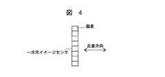
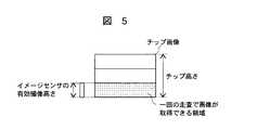
一般にパターンの欠陥検査では、被検査物体の画像を撮像する画像検出手段として一次元イメージセンサが用いられる。図4はイメージセンサの構成図であり、図5は、被検査物体の検査領域の平面図で、イメージセンサでパターンの検査領域を走査する場合に、一回の走査で画像が検出できる領域を示す。イメージセンサ8の光検出器の画素81の配列方向と直交する方向に検査対象物体を走査して二次元画像を取得する。複数の画素81が並んだ方向の長さをイメージセンサ8の高さと呼ぶ。また、被検査物体を製造中の複数の半導体チップを有する半導体ウェハとした場合、一つのチップのイメージセンサ8の高さと同じ方向の長さをチップ高さと呼ぶ。一般にチップ高さはイメージセンサ8の高さより大きいので、イメージセンサ8の一回の走査ではチップの部分の画像しか検出できない。このチップの部分画像の大きさは、検出を行うイメージセンサ8の高さと、チップ画像をこのイメージセンサ8に投影する結像光学系の結像倍率とで決まる。この高さをイメージセンサ8の有効撮像高さと呼ぶ。一般に使用されているイメージセンサと結像光学系の組合せでは、有効撮像高さはチップ高さより小さいので、チップ全面を検査するためには、複数回高さ方向にずらして走査する方法が用いられている。 In general, in pattern defect inspection, a one-dimensional image sensor is used as image detection means for capturing an image of an object to be inspected. FIG. 4 is a configuration diagram of the image sensor, and FIG. 5 is a plan view of the inspection area of the object to be inspected. When the image sensor scans the pattern inspection area, the area where the image can be detected by one scan is shown. Show. The inspection object is scanned in a direction orthogonal to the arrangement direction of the pixels 81 of the photodetector of the
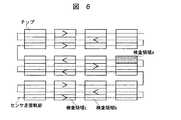
図6はウェハ上に形成された複数個のチップ21をイメージセンサで複数回走査する場合のセンサ走査軌跡101を示す平面図である。一般にパターン欠陥検査装置では、イメージセンサは固定されており、ステージを用いて被検査対象のウェハを移動させている。まずX方向に被検査物体を移動させて画像を取得する。一つのチップ21の画素毎の情報は走査順にメモリに記憶される。一回の走査で画像検出が終わった後、イメージセンサの有効撮像高さ分だけY方向に被検査物体を移動させ、図6では破線で示すように走査方向が逆になるようにステージを移動させ、これを繰り返すことで画像を順次検出する。 FIG. 6 is a plan view showing a sensor scanning trajectory 101 when a plurality of chips 21 formed on a wafer are scanned a plurality of times by an image sensor. In general, in a pattern defect inspection apparatus, an image sensor is fixed, and a wafer to be inspected is moved using a stage. First, an object to be inspected is moved in the X direction to acquire an image. Information for each pixel of one chip 21 is stored in the memory in the scanning order. After the image detection is completed in one scan, the object to be inspected is moved in the Y direction by the effective imaging height of the image sensor, and the stage is moved so that the scanning direction is reversed as shown by the broken line in FIG. By repeating this, images are detected sequentially.
チップ21の検査は同じパターン同士の画像比較により行われるが、領域bを検査する場合は、参照画像として検査領域cの画像を用いる。しかし、走査される各行の先頭チップである領域aを検査する場合には、同じパターンの一つ前の領域の参照画像が存在しないため、検査ができない。そのため、ウェハの外周に検査ができない領域が発生してしまう。以上の理由より、ウェハ外周チップで検査できないチップが発生する。 The inspection of the chip 21 is performed by comparing the images of the same pattern, but when inspecting the region b, the image of the inspection region c is used as a reference image. However, when inspecting the area a which is the first chip in each row to be scanned, the inspection cannot be performed because there is no reference image of the previous area of the same pattern. For this reason, an area that cannot be inspected occurs on the outer periphery of the wafer. For the above reasons, chips that cannot be inspected by the wafer outer peripheral chips are generated.
従来のパターン欠陥検査装置では、上記の問題を走査方法を変えることで解決したものも存在する(例えば、特許文献1参照)。図7は、図6と同じく、イメージセンサの走査軌跡を示す平面図である。この場合、イメージセンサの有効撮像高さがチップ高さの1/3であり、検査領域を短冊状に3つの領域に分けて走査するものとする。X方向の1行目の走査は図6に示したものと同様であるが、2行目は被検査物体をY方向へ1チップの高さ分だけ移動させ走査する。これを繰り返し、チップの1/3の領域分の同じパターンの画像を比較検査する。最後の行が終了したら、図6中に破線で示すように、チップの次の1/3の領域の同じパターンの画像を比較検査する。初めのチップが終了したら、チップの残りの1/3の領域の同じパターンの画像を比較検査する。 Some conventional pattern defect inspection apparatuses have solved the above problem by changing the scanning method (see, for example, Patent Document 1). FIG. 7 is a plan view showing the scanning trajectory of the image sensor, as in FIG. In this case, the effective imaging height of the image sensor is 1/3 of the chip height, and the inspection area is scanned into three areas in a strip shape. The scanning in the first row in the X direction is the same as that shown in FIG. 6, but in the second row, scanning is performed by moving the object to be inspected by the height of one chip in the Y direction. This is repeated, and comparative inspection is performed on images of the same pattern corresponding to 1/3 of the chip area. When the last line is completed, as shown by a broken line in FIG. 6, an image of the same pattern in the next 1/3 area of the chip is comparatively inspected. When the first chip is completed, an image of the same pattern in the remaining 1/3 of the chip is comparatively inspected.
折返し直後の領域bを検査する場合、参照画像となる領域cの画素情報の読み出しは記憶時の順序とは逆の順序で読み出すことによって、領域bと領域cとを同一パターンの画像として比較検査ができる。なお、検査の開始の時の領域aの参照画像として、予め同じパターンの他の領域の画像を記憶させておくことにより、領域aの検査も可能とすることができる。
しかし、図6に示される走査軌跡で検査を行うパターン欠陥検査装置でも、また図6に示される走査軌跡で検査を行うパターン欠陥検査装置でも、あるチップの検出画像の比較検査は直前の同一パターンのチップの参照画像と比較することにより行っている。このように直前の一つのチップの画像を参照画像とすることによって以下の問題が生じる。When inspecting the area b immediately after folding, the pixel information of the area c to be a reference image is read out in an order opposite to the order at the time of storage, thereby comparing the area b and the area c as images of the same pattern. Can do. Note that, by storing an image of another region in the same pattern in advance as a reference image of the region a at the start of the inspection, the region a can be inspected.
However, in both the pattern defect inspection apparatus that inspects with the scanning locus shown in FIG. 6 and the pattern defect inspection apparatus that inspects with the scanning locus shown in FIG. This is done by comparing with the reference image of the chip. Thus, the following problem arises by using the image of the immediately preceding chip as the reference image.
一般にパターン欠陥検査の対象となる被検査物体においては、フォトレジストやSiO2等の絶縁膜のように、可視光の波長に対して透明な材料でパターンが形成されていることが多い。この場合、薄膜が欠陥検査装置で使用している光の波長に対して透明であっても、光の干渉効果によって、その光の波長とパターンを形成する材料の屈折率および膜厚で決まる反射率を示すことから、欠陥検査装置ではその存在を明暗の画像として検出することができる。図1は欠陥検査装置で使用している光の波長に対して透明な材料で薄膜状のパターンが形成されているウェハの例を示す。一般にこのようなウェハにおいては、薄膜パターンの膜厚はウェハ全面で完全に均一とはならず、場所によって膜厚が若干異なる現象を生じるが、ある程度の膜厚誤差はこのような半導体チップの製造上影響がないものとして許容される。しかし、場所によって膜厚が異なると、パターンの反射率が異なるため、検出される画像の明るさに差を生じる。このような現象を色ムラと称する。例えば、図1の隣り合うチップnと直前のチップn−1で、その中に含まれる同一形状のパターンpにおける膜厚が異なり色ムラが生じているとする。この場合、チップnを検出画像、チップn−1を参照画像として比較検査を行うと、パターンpはこれらの2画像間で形状が同一で、欠陥が存在しないにも関わらず、画像としての明暗が異なるため、欠陥であるとして誤検出されてしまう。このような偽の欠陥情報は、真の欠陥との区別が困難になるため、検査装置の信頼性に大きく関わる問題である。In general, an object to be inspected for pattern defect inspection often has a pattern formed of a material transparent to the wavelength of visible light, such as an insulating film such as a photoresist or SiO2 . In this case, even if the thin film is transparent to the wavelength of the light used in the defect inspection apparatus, the reflection is determined by the light wavelength and the refractive index and thickness of the material forming the pattern due to the light interference effect. Since the rate is indicated, the presence of the defect inspection apparatus can be detected as a bright and dark image. FIG. 1 shows an example of a wafer on which a thin film pattern is formed of a material transparent to the wavelength of light used in the defect inspection apparatus. In general, in such a wafer, the film thickness of the thin film pattern is not completely uniform over the entire surface of the wafer, and the film thickness varies slightly depending on the location. Allowed as having no effect on the top. However, when the film thickness varies depending on the location, the reflectance of the pattern differs, so that a difference occurs in the brightness of the detected image. Such a phenomenon is called color unevenness. For example, it is assumed that the adjacent chip n in FIG. 1 and the immediately preceding chip n−1 have different film thicknesses in the same-shaped pattern p included therein and cause color unevenness. In this case, when the comparison inspection is performed using the chip n as the detection image and the chip n-1 as the reference image, the pattern p has the same shape between these two images, and the light and darkness as the image is not present even though there is no defect. Are different from each other and are erroneously detected as defects. Such fake defect information is a problem that greatly affects the reliability of the inspection apparatus because it is difficult to distinguish it from true defects.
従来から、このような偽の欠陥情報を拾わないようにするための対策として、
(1)検出画像と参照画像を比較検査する際に、どのくらいの差をもって優位差有りと判定するかの基準となる閾値を色ムラを拾わない程度に大きくする。
(2)検出画像−参照画像間に生じている色ムラの影響を補正してやり、色ムラを除去した状態で比較検査を行う。
という2つの方法が行われている。しかし(1)の方法は、検査装置の検出感度を下げることに他ならず、真の欠陥に対しての検出能力も同時に低下する問題がある。また(2)は、例えば特許文献2に示されているような方法であるが、検出画像のチップ位置における色ムラの程度を、直前のチップの参照画像から推定することは、即ち過去の既知情報から未来の未知情報を外挿により推定することであり、また利用できる情報が検出画像1面と参照画像1面の2画像分と少ないため、色ムラの影響を補正・除去できる効果が限られているという問題があった。Conventionally, as a measure to prevent picking up such fake defect information,
(1) When comparing and inspecting a detected image and a reference image, a threshold value that is a criterion for determining a difference in superiority is increased to the extent that color unevenness is not picked up.
(2) The influence of color unevenness occurring between the detected image and the reference image is corrected, and a comparative inspection is performed in a state where the color unevenness is removed.
Two methods are used. However, the method (1) has a problem that the detection capability of the true defect is also reduced at the same time as reducing the detection sensitivity of the inspection apparatus. Further, (2) is a method as shown in Patent Document 2, for example, but estimating the degree of color unevenness at the chip position of the detected image from the reference image of the immediately preceding chip is a past known This is to estimate future unknown information from the information by extrapolation, and since there is little information available for two images of one detection image and one reference image, the effect of correcting / removing the influence of color unevenness is limited. There was a problem of being.
特許文献3には、繰り返される被検査パターンから画像信号を検出し、この検出された画像信号から繰り返される被検査パターンの統計画像信号を生成し、この生成された統計画像信号を基準画像信号として前記検出された画像信号と位置合わせして比較することによって被検査パターンに存在する欠陥または欠陥候補を抽出する被検査パターン検査方法が記載されている。 In Patent Document 3, an image signal is detected from a repeated pattern to be inspected, a statistical image signal of the pattern to be inspected is generated from the detected image signal, and the generated statistical image signal is used as a reference image signal. An inspection pattern inspection method for extracting defects or defect candidates existing in an inspection pattern by aligning and comparing with the detected image signal is described.
特許文献4には、第1のパターンを順次取り込む手段と、該手段で取り込まれた第1のパターン加算平均を算出し、第2のパターンを生成するパターン生成手段と、生成された第2のパターンと、新たに取り込まれた第1のパターンとを比較し、そのパターン差を検出する手段とを備え、パターン差によって欠陥を検出する表面欠陥検査装置が記載されている。 In Patent Document 4, a first pattern is sequentially fetched, a pattern generation means for calculating a first pattern addition average fetched by the means, and generating a second pattern, and a generated second pattern A surface defect inspection apparatus is provided that includes a means for comparing a pattern with a newly taken first pattern and detecting the pattern difference, and detecting a defect by the pattern difference.
特許文献5には、1枚のウェハをダイシングすることによって得られる複数の半導体チップの濃淡情報を順次一時的に記憶する第1画像メモリと、上記第1の画像メモリの濃淡情報と比較判定を行うための基準の濃淡情報を記憶する第2の画像メモリと、上記第1画像メモリと第2画像メモリの濃淡情報を比較し良品の半導体チップを検出する良品検出部と、上記良品検出部が良品と判断した時に上記第1画像メモリと第2画像メモリの濃淡情報の演算を行い、該演算結果で第2画像メモリの濃淡情報を書き替え、新らたな基準の濃淡情報となるようにする画像平均化処理部を具備した半導体チップの外観検査装置が記載されている。 In Patent Document 5, a first image memory that temporarily and temporarily stores grayscale information of a plurality of semiconductor chips obtained by dicing a single wafer, and a comparison determination with the grayscale information of the first image memory. A second image memory for storing reference grayscale information to perform, a non-defective product detection unit for comparing the grayscale information of the first image memory and the second image memory to detect a non-defective semiconductor chip, and the non-defective product detection unit When it is determined that the product is non-defective, the shading information of the first image memory and the second image memory is calculated, and the shading information of the second image memory is rewritten based on the calculation result so that the new reference shading information is obtained. A semiconductor chip appearance inspection apparatus including an image averaging processing unit is described.
本発明の目的は、透明薄膜でパターンが形成されており、検出画像の位置と参照画像の位置でその膜厚が異なっている場合においても、パターン欠陥の検査精度を向上させることを可能としたパターン欠陥検査装置およびパターン欠陥検査方法を提供することにある。 An object of the present invention is to make it possible to improve the inspection accuracy of pattern defects even when a pattern is formed of a transparent thin film and the film thickness differs between the position of the detected image and the position of the reference image. A pattern defect inspection apparatus and a pattern defect inspection method are provided.
上記目的を達成するために、本発明は、被検査物体上に行列方向に等間隔で連続的に配列された同一形状を有するパターンのうち、検出画像に隣接する少なくとも検出画像を挟んだ前後を含む2以上の複数の同一形状のパターンの画像から平均参照画像を生成する。 In order to achieve the above object, the present invention provides a pattern having the same shape continuously arranged at equal intervals in the matrix direction on the inspected object before and after sandwiching at least the detection image adjacent to the detection image. An average reference image is generated from two or more images of a pattern having the same shape.
そのために本発明は、検出画像と、検出画像に隣接する少なくとも検出画像を挟んだ前後を含む2以上の複数の同一形状のパターンの画像を記憶する画像記憶手段と、それらの記憶された画像から統計的演算処理により平均参照画像を生成する平均参照画像生成手段と、検出画像とその平均参照画像を比較検査して欠陥を検出する画像比較手段を備える。 To this end, the present invention provides an image storage means for storing a detected image, two or more images of the same shape including at least the detection image adjacent to the detected image, and the stored images. Average reference image generating means for generating an average reference image by statistical calculation processing, and image comparison means for detecting a defect by comparing and inspecting the detected image and the average reference image.
本発明は、更に上下方向の2つのパターンを加えて平均参照画像を検出画像の上下左右4つの同一形状のパターンから統計的演算処理により生成することを特徴とする。 The present invention is further characterized in that by adding two patterns in the vertical direction, an average reference image is generated by statistical calculation processing from four patterns of the same shape in the vertical and horizontal directions of the detected image.
この構成によれば、参照画像を少なくとも検出画像を挟んだ左右および上下の4つの画像から生成することによって検出画像位置での色ムラの状態に近い状態の参照画像を得ることができるため、この参照画像と検出画像とを比較検査する際に色ムラの影響を効果的に軽減することができ、色ムラの影響の大きい被検査物体においてもパターン欠陥の検査精度を向上させることを可能とした欠陥検査装置および欠陥検査方法を提供することができる。 According to this configuration, since the reference image is generated from at least four images on the left, right, and upper and lower sides with the detection image interposed therebetween, a reference image in a state close to the state of color unevenness at the detection image position can be obtained. The effect of color unevenness can be effectively reduced when comparing and inspecting the reference image and the detected image, and it has become possible to improve the inspection accuracy of pattern defects even for inspected objects that are greatly affected by color unevenness. A defect inspection apparatus and a defect inspection method can be provided.
本発明によれば、被検査物体上に透明薄膜でパターンが形成されていて、その透明薄膜の膜厚が被検査物体上の位置によって変化している場合においても、色ムラの影響を除去または軽減し、高い検査精度で欠陥を検出できるパターン欠陥検査装置を実現できる。 According to the present invention, even when a pattern is formed of a transparent thin film on an object to be inspected and the film thickness of the transparent thin film changes depending on the position on the object to be inspected, A pattern defect inspection apparatus that can reduce and detect defects with high inspection accuracy can be realized.
本発明のパターン欠陥検査装置は、被検査物体上に行列方向に等間隔で連続的に配列された同一形状を有するパターンをイメージセンサを走査して得られる検出画像とその行列方向に隣接する同一形状のパターンを走査して得られる参照画像とを比較して欠陥を検出するパターン欠陥検査装置であって、検出画像に隣接する少なくとも検出画像を挟んだ左右上下斜めに隣接する最近接8チップを含んで同一形状のパターンの画像から統計的演算処理により平均参照画像を生成する手段と検出画像を生成された平均参照画像と比較して欠陥を検出する手段とを備えたことを特徴とする。 The pattern defect inspection apparatus of the present invention is the same as a detection image obtained by scanning an image sensor with a pattern having the same shape continuously arranged at equal intervals in the matrix direction on the object to be inspected and the same adjacent in the matrix direction. A pattern defect inspection apparatus that detects a defect by comparing a reference image obtained by scanning a pattern of a shape, and includes at least eight adjacent chips that are adjacent to the detection image and that are diagonally adjacent to each other at least vertically And a means for generating an average reference image from an image having the same shape by statistical calculation processing and a means for detecting a defect by comparing the detected image with the generated average reference image.
この構成によれば、参照画像を少なくとも検出画像を挟んだ左右上下および斜めに隣接する最近接する8つの画像から生成することによって検出画像位置での色ムラの状態に近い状態の参照画像を得ることができるため、この参照画像と検出画像とを比較検査する際に色ムラの影響を効果的に軽減することができ、色ムラの影響の大きい被検査物体においてもパターン欠陥の検査精度を向上させることを可能とした欠陥検査装置および欠陥検査方法を提供することができる。 According to this configuration, a reference image in a state close to the state of color unevenness at the detected image position can be obtained by generating the reference image from at least eight images adjacent to each other at the left, right, up, down, and diagonally with the detected image interposed therebetween. Therefore, it is possible to effectively reduce the influence of color unevenness when performing a comparative inspection between the reference image and the detected image, and to improve the inspection accuracy of pattern defects even for an object to be inspected that is greatly affected by color unevenness. It is possible to provide a defect inspection apparatus and a defect inspection method that make it possible.
平均参照画像を生成する統計的演算処理は、検出画像の上下左右斜めに隣接する最近接する同一形状のパターンの単純平均を行う。
あるいは、平均参照画像を生成する統計的演算処理は、検出画像の上下左右斜めに隣接する最近接する8つの同一形状のパターンから適合する2次曲面を算出する処理を行う。The statistical calculation processing for generating an average reference image performs a simple average of patterns of the same shape that are closest to each other adjacent to the detected image in the upper, lower, left, and right directions.
Alternatively, the statistical calculation process for generating the average reference image performs a process of calculating a matching quadric surface from eight patterns of the same shape that are closest to each other in the vertical and horizontal directions of the detected image.
適合する2次曲面を求める計算手法は、最小二乗法であり、その計算の際に同時に平均二乗誤差を算出する手段とその平均二乗誤差を用いて欠陥検出判定時の閾値を決定する手段とその閾値にもとづいて欠陥の有無を判定する手段を備える。 A calculation method for obtaining a suitable quadratic surface is a least square method. At the same time, a means for calculating a mean square error, a means for determining a threshold value at the time of defect detection using the mean square error, and Means for determining the presence or absence of a defect based on the threshold value is provided.
本発明は、また被検査物体上に行列方向に等間隔で連続的に配列された同一形状を有するパターンをイメージセンサを走査して得られる検出画像とその行列方向に隣接する同一形状のパターンを走査して得られる参照画像とを比較して欠陥を検出するパターン欠陥検査装置において、検出画像に隣接する少なくとも検出画像を挟んだ左右上下斜めに隣接する少なくとも最近接8チップの同一形状のパターンと検出画像の両方から統計的演算処理により平均参照画像を生成する手段と検出画像をその生成された平均参照画像と比較して欠陥を検出する手段とを備えたパターン欠陥検査装置として構成することができる。 The present invention also provides a detection image obtained by scanning an image sensor with a pattern having the same shape continuously arranged at equal intervals in the matrix direction on the object to be inspected and a pattern having the same shape adjacent in the matrix direction. In a pattern defect inspection apparatus that detects a defect by comparing with a reference image obtained by scanning, a pattern having the same shape of at least the nearest 8 chips that are adjacent to each other in the left-right and up-down directions sandwiching at least the detection image adjacent to the detection image A pattern defect inspection apparatus comprising means for generating an average reference image from both detected images by statistical calculation processing and means for detecting a defect by comparing the detected image with the generated average reference image. it can.
本発明の一実施例を、図面を参照して説明する。
図8は、パターン欠陥検査装置の概略構成図である。被検査物体であるウェハ3は、高さ方向への移動と回転が可能なZθステージ2上に固定され、Zθステージ2は水平方向であるX方向とY方向に移動可能なXYステージ1の上に設置されている。An embodiment of the present invention will be described with reference to the drawings.
FIG. 8 is a schematic configuration diagram of the pattern defect inspection apparatus. A wafer 3 that is an object to be inspected is fixed on a Zθ stage 2 that can move and rotate in the height direction, and the Zθ stage 2 is placed on an
ウェハ3の上方には、照明光源4からの照明光をウェハ3側へ向けるハーフミラー5があり、対物レンズ6を経てウェハ3を照明する。ウェハ3上で反射された反射光は対物レンズ6、ハーフミラー5を経て、検出光としてイメージセンサ8で受光される構成となっている。また、ハーフミラー7で分岐された光は自動焦点検出手段9に入り、最適焦点位置を算出し、Zθステージ2のZステージに移動指令を与え、最適焦点で画像が検出できるようになっている。イメージセンサ8で受光された検出光は、A/D変換器10を通じてデジタル信号に変換され、画像記憶手段11に記録される。 Above the wafer 3, there is a half mirror 5 for directing illumination light from the illumination light source 4 toward the wafer 3, and illuminates the wafer 3 through the objective lens 6. The reflected light reflected on the wafer 3 passes through the objective lens 6 and the half mirror 5 and is received by the
一般にチップ高さはイメージセンサ8の有効撮像高さより大きいので、チップ21の全面を検査するためには、チップ21の領域をイメージセンサの有効撮像高さで分割し、複数回高さ方向にずらして走査する。一例としてイメージセンサの有効撮像高さがチップ高さの1/3であり、検査領域を短冊状に3つの領域に分けて走査するものとすると、走査の手順は図7に示すように、X方向の1行目の走査を左から右へ行った後、2行目は被検査物体をY方向へ1チップの高さ分だけ移動させ走査する。これを繰り返し、チップの1/3の領域分の同じパターンの画像を比較検査する。最後の行が終了したら、図7中に破線で示すように、チップの次の1/3の領域の同じパターンの画像を比較検査する。初めのチップが終了したら、チップの残りの1/3の領域の同じパターンの画像を比較検査することによりチップ21全面の検査を終了する。 Since the chip height is generally larger than the effective imaging height of the
後述のように本発明の実施例では、検出画像と比較検査をする対象になる参照画像を、検出画像のチップに対し上下左右斜めに隣接する最近接8チップの画像から生成する。このため、前出の画像検出手段11は3行分のチップ列に対してイメージセンサ8の有効撮像高さ分の全画像を記憶できる容量が必要となる。ここで「左右」とは検出画像の走査方向の前後であり、「上下」とは走査方向がチップ高さだけ変えられて折り返したときの検出画像の上下ということであり、「斜めに隣接する」とは走査方向がチップ高さだけ変えられて折り返したときの「上下」に隣接する4つの画像を意味する。詳細は図2に示される。被検査対象ウェハの直径を300mm、検査時の画素寸法(被検査物体上での寸法)を0.2μm×0.2μm、イメージセンサの高さ方向の総画素数を4,096とし、各画素毎の画像情報の格納に1byteを要するとした場合、必要な容量は、
300mm÷0.2μm×4,096×1byte×3=約17Gbyte
(ただし1Gbyte=1,073,741,824byte)
となる。従来このような大容量は記録速度のきわめて遅い磁気記憶媒体によってのみ実現可能であったため検査中に実時間で処理を行う必要のあるパターン欠陥検査装置ではこのような技術を実現することは現実的ではなかったが、最近の半導体素子の進歩により、この程度の記憶容量は半導体メモリの集合で十分実現可能となってきた。As will be described later, in the embodiment of the present invention, the detected image and the reference image to be subjected to the comparative inspection are generated from the image of the nearest 8 chips adjacent to the detected image chip vertically and horizontally. For this reason, the above-described image detection means 11 needs to have a capacity capable of storing all images corresponding to the effective imaging height of the
300mm ÷ 0.2μm × 4,096 × 1byte × 3 = about 17Gbyte
(However, 1 Gbyte = 1,073,741,824 bytes)
It becomes. Conventionally, such a large capacity could only be realized by a magnetic storage medium with a very slow recording speed, so it is realistic to realize such a technique in a pattern defect inspection apparatus that requires processing in real time during inspection. However, with recent advances in semiconductor devices, this level of storage capacity has become sufficiently realizable with a collection of semiconductor memories.
図2は、半導体ウェハおよび拡大部の平面図である。本実施例のパターン欠陥検査では、検査領域に隣接する領域の画像を記憶して参照画像とし、この参照画像と検査領域の画像とを比較し、両者の差異の部分を欠陥として抽出する。図2に示すような1枚のウェハ3上には、個別に製品となるチップ21が複数個配列されている。これらのチップ21は同一形状のパターンとして行列方向に一定間隔で連続的に配置されている。ここでは、チップ(m,n)内の検査領域aにおける欠陥の有無を検出する場合の動作について説明を行う。被検査対象のウェハを図中下から順次、第n−1行、第n行、第n+1行と走査し、第n+1行の第m+1列のチップまで走査が終了し画像が画像記憶手段11に記憶されると、平均参照画像生成手段12は、
(m−1,n−1)
(m ,n−1)
(m+1,n−1)
(m−1,n )
(m+1,n )
(m−1,n+1)
(m ,n+1)
(m+1,n+1)
の8画像の対応する画素の信号強度の単純平均(算術平均)を順次計算することにより、これら8画像の平均としての平均参照画像を生成する。ただし、第n−1行および第n+1行の各チップと第n行の各チップとは、ステージの走査方向が逆になっているため、記憶画像の読み出し時は逆方向に読み出すことで画像情報の方向を合わせる。FIG. 2 is a plan view of the semiconductor wafer and the enlarged portion. In the pattern defect inspection of the present embodiment, an image of an area adjacent to the inspection area is stored as a reference image, the reference image is compared with the image of the inspection area, and the difference between the two is extracted as a defect. On a single wafer 3 as shown in FIG. 2, a plurality of chips 21 as individual products are arranged. These chips 21 are continuously arranged at regular intervals in the matrix direction as patterns having the same shape. Here, an operation for detecting the presence or absence of a defect in the inspection area a in the chip (m, n) will be described. The wafer to be inspected is sequentially scanned from the bottom in the figure to the (n−1) th row, the nth row, and the (n + 1) th row, and the scanning is completed up to the chip in the (n + 1) th row to the (m + 1) th column, and When stored, the average reference image generation means 12
(M-1, n-1)
(M, n-1)
(M + 1, n-1)
(M-1, n)
(M + 1, n)
(M-1, n + 1)
(M, n + 1)
(M + 1, n + 1)
By sequentially calculating a simple average (arithmetic average) of signal intensities of corresponding pixels of the eight images, an average reference image as an average of these eight images is generated. However, since the scanning directions of the stages of the chips of the (n−1) th and (n + 1) th rows and the respective chips of the nth row are reversed, the image information can be read by reading the stored image in the reverse direction. Align the direction of.
次にチップ(m,n)の画像が検出画像として読み出され、前記平均参照画像と共に画像比較手段13に渡される。画像比較手段では、これら2画像の対応する画素の信号強度の比較を順次行い、指定された閾値以上の差が発見された画素が欠陥として検出される。 Next, the image of the chip (m, n) is read out as a detected image and transferred to the image comparison means 13 together with the average reference image. The image comparison means sequentially compares the signal intensities of corresponding pixels of these two images, and a pixel in which a difference equal to or greater than a specified threshold is found is detected as a defect.
本実施例において生成される平均参照画像は、検出画像のチップを挟んで上下左右斜めに最近接する8チップから算出されるため、これら周囲の8チップの画像から中央のチップ位置における画像を内挿によって求めていることになる。このため、パターンを形成している透明薄膜の膜厚がチップの間隔に対して急激に増減の変化をしている特殊な場合を除き、この平均参照画像に含まれる色ムラの状態は、これら8チップの中央に位置する検出画像のチップにおける色ムラの状態に十分近いことが期待できる。一般に、半導体ウェハではチップの間隔はウェハ直径の1/10以下であり、膜厚誤差が製品としての許容範囲内にある半導体ウェハにおいては、パターンを形成している透明薄膜の膜厚の変化がチップの間隔内では単調に増加または減少する分布をとっていると仮定して差し支えない。このように本実施例の欠陥検査方法では、[背景技術]で記載した、例えば特許文献2に示されているような、検出画像のチップ位置における色ムラの程度を、検出画像1面と直前のチップの参照画像1面の合計2画像分の情報のみを用いて推定し補正する方法に比べ、簡単な計算処理で確実な効果を得ることが可能である。 Since the average reference image generated in the present embodiment is calculated from the eight chips closest to each other in the vertical and horizontal directions with the detected image chip interposed therebetween, the image at the center chip position is interpolated from the surrounding eight chip images. Will be asking for. For this reason, except for the special case where the film thickness of the transparent thin film that forms the pattern changes abruptly with respect to the chip interval, the state of color unevenness included in this average reference image is It can be expected to be sufficiently close to the state of color unevenness in the chip of the detected image located at the center of the 8 chips. In general, in a semiconductor wafer, the distance between chips is 1/10 or less of the wafer diameter, and in a semiconductor wafer in which the film thickness error is within the allowable range as a product, the film thickness of the transparent thin film forming the pattern changes. It can be assumed that the distribution is monotonically increasing or decreasing within the chip interval. As described above, in the defect inspection method according to the present embodiment, the degree of color unevenness at the chip position of the detected image described in [Background Art], for example, as shown in Patent Document 2, is detected immediately before the surface of the detected image. Compared with the method of estimating and correcting using only the information for a total of two images of one reference image surface of the chip, it is possible to obtain a reliable effect with a simple calculation process.
なお、上記では平均参照画像を、各画素毎に検出画像周辺の最近接8チップの単純平均(算術平均)を計算することで求めているが、これら8チップの画像の対応する各画素毎に、最小二乗法によって最も良く適合する2次曲面
g(x、y)=ax2+by2+cxy+dx+ey+f ……(式1)
を求め、中央の検出画像のチップ位置におけるこのg(x、y)の値をその画素の明るさについての信号強度として求めるようにしても良い。すなわち、平均参照画像を生成する統計的演算方法が、最近接8チップの画像の対応する各画素上の明るさの信号強度についての2次曲面を算出し、検出画像のg(x、y)点における画素に対応する2次曲面上の信号強度を求め、この平均信号強度と前述のg(x、y)点における信号とを比較することを行う。図3は、2次曲面図である。黒点は、各チップ画像内の位置(x、y)における信号強度を表し、黒丸の8点から統計的演算で二次曲面を算出し、星印で示す検出チップ画像内の位置(x、y)における信号強度に対して算出した二次曲面上の、検出に対応する位置の信号強度を求める。途中の計算過程は省略するが、この計算は非常に簡単な結果となり、平均参照画像の各画素の信号値は、チップ(p,q)における着目した画素の信号値をIp,qと表記すると、
Im,n =−0.25×Im-1,n+1+0.5×Im,n+1−0.25×Im+1,n+1
+0.5 ×Im-1,n +0.5 ×Im+1.n
−0.25×Im-1,n-1+0.5×Im,n-1−0.25×Im+1,n-1
と計算することができる。この方法では、単純平均(算術平均)に比べ、計算はやや複雑になるが、チップ間隔に対して膜厚がより急に変化している場合でも、より精度の高い平均参照画像を生成することができる利点がある。In the above description, the average reference image is obtained by calculating the simple average (arithmetic average) of the nearest 8 chips around the detected image for each pixel, but for each corresponding pixel of the 8-chip image. , A quadratic surface that fits best by the least squares method g (x, y) = ax2 + by2 + cxy + dx + ey + f (Equation 1)
And the value of g (x, y) at the chip position of the center detection image may be obtained as the signal intensity for the brightness of the pixel. That is, the statistical calculation method for generating the average reference image calculates a quadratic surface for the signal intensity of the brightness on each corresponding pixel of the closest 8-chip image, and g (x, y) of the detected image The signal intensity on the quadric surface corresponding to the pixel at the point is obtained, and the average signal intensity is compared with the signal at the aforementioned g (x, y) point. FIG. 3 is a quadratic curved surface view. The black point represents the signal intensity at the position (x, y) in each chip image, a quadratic surface is calculated by statistical calculation from the eight points of the black circle, and the position (x, y) in the detection chip image indicated by an asterisk. The signal intensity at the position corresponding to the detection on the quadric surface calculated with respect to the signal intensity in (1) is obtained. Although the calculation process in the middle is omitted, this calculation has a very simple result, and the signal value of each pixel of the average reference image is expressed as Ip, q as the signal value of the pixel of interest in the chip (p, q). ,
Im, n = −0.25 × Im-1, n + 1 + 0.5 × Im, n + 1−0.25 × Im + 1,
+0.5 × Im-1, n +0.5 × Im + 1.n
−0.25 × Im−1, n−1 + 0.5 × Im, n−1−0.25 × Im + 1, n−1
And can be calculated. This method is slightly more complex than simple average (arithmetic average), but produces a more accurate average reference image even when the film thickness changes more rapidly than the chip interval. There is an advantage that can be.
またこの最小二乗法を用いる方法では、適合する2次曲面を求める際、同時に平均二乗誤差(求めた2次曲線と、元の標本データとの二乗誤差の期待値)を求めることができることから、別の利点もある。一般に、欠陥を持たない同一形状のパターン同士を比較する場合でも、画像信号に重畳する種々の雑音成分や、欠陥には分類しない程度の微少な形状のゆらぎ等の存在により、画像の差を計算すると必ずしもゼロとはならない。そのため欠陥の有無を判定する際には、画像の差が閾値として予め設定された一定値を超えた場合にのみ欠陥として検出する必要がある。しかし閾値の決定は、大きすぎると感度が必要以上に低下し、また小さすぎると実際には欠陥がない場合でも雑音成分等を拾って偽の欠陥情報を発生してしまう、というように適切に設定するには困難が伴う。この平均二乗誤差は、これら8チップに含まれる同一形状のパターンが、この2次曲線を用いて色ムラ等の影響を補正した後でも、どのくらいバラツキを持っているかの指標となるため、欠陥の有無を判定する際の閾値を検査中にこの数値を用いて動的に決定すると、実際のバラツキを反映して閾値を決定することができ、雑音成分やパターン形状のゆらぎが大きいところでは自動的に閾値を増加させ、逆にそれらの影響の小さいところでは自動的に閾値を下げて検査することが可能になり、効果的に欠陥を検出できる利点が得られる。 In addition, in the method using the least square method, when obtaining a suitable quadric surface, it is possible to simultaneously obtain the mean square error (expected value of the square error between the obtained quadratic curve and the original sample data). There is another advantage. In general, even when comparing patterns with the same shape that do not have defects, image differences are calculated due to the presence of various noise components superimposed on the image signal and fluctuations in the shape that are not classified as defects. Then it is not necessarily zero. Therefore, when determining the presence or absence of a defect, it is necessary to detect it as a defect only when the difference between the images exceeds a predetermined value set as a threshold value. However, if the threshold is set too high, the sensitivity will drop more than necessary, and if it is too low, it will pick up noise components and generate false defect information even if there is actually no defect. Difficult to set up. This mean square error is an indicator of how much variation the patterns of the same shape included in these 8 chips have even after correcting the influence of color unevenness using this quadratic curve. If this value is used to dynamically determine the threshold for determining the presence or absence during inspection, the threshold can be determined to reflect actual variations, and automatically when there are large fluctuations in noise components or pattern shapes. On the contrary, it is possible to inspect by automatically reducing the threshold when the influence is small, and the defect can be detected effectively.
1…XYステージ、2…Zθステージ、3…ウェハ、4…照明光源、5、7…ハーフミラー、6…対物レンズ、8…イメージセンサ、9…自動焦点検出手段、10…A/D変換器、11…画像記憶手段、12…平均参照画像生成手段、13…画像比較手段、21…チップ、81…画素。
DESCRIPTION OF
Claims (3)
Translated fromJapanese前記平均参照画像を生成する統計的演算処理が、前記最近接8チップの画像の対応する各画素上の信号強度についての2次曲面を算出し、前記検出画像のg(x、y)点における画素に対応する画素についての2次曲面上の平均信号強度を求め、平均信号強度と前記g(x、y)点における信号強度と比較することからなることを特徴とするパターン欠陥検査装置。Obtained by scanning a detected image obtained by scanning an image sensor with a pattern having the same shape continuously arranged at equal intervals in the matrix direction on the object to be inspected and a pattern having the same shape adjacent in the matrix direction. In a pattern defect inspection apparatus that detects a defect by comparing with a reference image,statistically from an image of a pattern having the same shape including the nearest eight chips that are adjacent to each other at least in the verticaland horizontal directions sandwiching at least the detection image adjacent to the detection imageMeans for generating an average reference image by arithmetic processing and means for detecting a defect by comparing the detected image with the generated average reference image;
The statistical calculation processing for generating the average reference image calculates a quadratic surface for the signal intensity on each corresponding pixel of the nearest 8-chip image, and at the g (x, y) point of the detected image. calculating an average signal intensity on the quadratic surface for the pixel corresponding to the pixel, the average signal intensity and the g (x, y) pattern defect inspection apparatus characterized thatyou consists in comparing the signal strength at point.
Priority Applications (5)
| Application Number | Priority Date | Filing Date | Title |
|---|---|---|---|
| JP2003398312AJP4351522B2 (en) | 2003-11-28 | 2003-11-28 | Pattern defect inspection apparatus and pattern defect inspection method |
| US10/995,512US7457455B2 (en) | 2003-11-28 | 2004-11-24 | Pattern defect inspection method and apparatus |
| US12/216,642US7853068B2 (en) | 2003-11-28 | 2008-07-09 | Pattern defect inspection method and apparatus |
| US12/249,328US7616805B2 (en) | 2003-11-28 | 2008-10-10 | Pattern defect inspection method and apparatus |
| US12/573,482US20100021041A1 (en) | 2003-11-28 | 2009-10-05 | Pattern defect inspection method and apparatus |
Applications Claiming Priority (1)
| Application Number | Priority Date | Filing Date | Title |
|---|---|---|---|
| JP2003398312AJP4351522B2 (en) | 2003-11-28 | 2003-11-28 | Pattern defect inspection apparatus and pattern defect inspection method |
Publications (2)
| Publication Number | Publication Date |
|---|---|
| JP2005156475A JP2005156475A (en) | 2005-06-16 |
| JP4351522B2true JP4351522B2 (en) | 2009-10-28 |
Family
ID=34616565
Family Applications (1)
| Application Number | Title | Priority Date | Filing Date |
|---|---|---|---|
| JP2003398312AExpired - Fee RelatedJP4351522B2 (en) | 2003-11-28 | 2003-11-28 | Pattern defect inspection apparatus and pattern defect inspection method |
Country Status (2)
| Country | Link |
|---|---|
| US (4) | US7457455B2 (en) |
| JP (1) | JP4351522B2 (en) |
Families Citing this family (87)
| Publication number | Priority date | Publication date | Assignee | Title |
|---|---|---|---|---|
| JP4351522B2 (en)* | 2003-11-28 | 2009-10-28 | 株式会社日立ハイテクノロジーズ | Pattern defect inspection apparatus and pattern defect inspection method |
| KR101056142B1 (en) | 2004-01-29 | 2011-08-10 | 케이엘에이-텐코 코포레이션 | Computerized method for detecting defects in reticle design data |
| JP4904034B2 (en) | 2004-09-14 | 2012-03-28 | ケーエルエー−テンカー コーポレイション | Method, system and carrier medium for evaluating reticle layout data |
| US7128992B2 (en) | 2004-12-16 | 2006-10-31 | Utc Fuel Cells, Llc | Dual pump fuel cell temperature management system |
| US8194946B2 (en)* | 2005-07-28 | 2012-06-05 | Fujifilm Corporation | Aligning apparatus, aligning method, and the program |
| US7769225B2 (en) | 2005-08-02 | 2010-08-03 | Kla-Tencor Technologies Corp. | Methods and systems for detecting defects in a reticle design pattern |
| KR100648201B1 (en)* | 2005-08-08 | 2006-11-23 | 삼성전자주식회사 | Substrate inspection method and substrate inspection apparatus for performing the same |
| US7570796B2 (en) | 2005-11-18 | 2009-08-04 | Kla-Tencor Technologies Corp. | Methods and systems for utilizing design data in combination with inspection data |
| US7676077B2 (en) | 2005-11-18 | 2010-03-09 | Kla-Tencor Technologies Corp. | Methods and systems for utilizing design data in combination with inspection data |
| US8041103B2 (en) | 2005-11-18 | 2011-10-18 | Kla-Tencor Technologies Corp. | Methods and systems for determining a position of inspection data in design data space |
| DE102006005800B4 (en)* | 2006-02-08 | 2007-12-06 | Atg Test Systems Gmbh | Method and apparatus for testing unpopulated printed circuit boards |
| JP4165580B2 (en)* | 2006-06-29 | 2008-10-15 | トヨタ自動車株式会社 | Image processing apparatus and image processing program |
| JP5466811B2 (en)* | 2006-11-22 | 2014-04-09 | オリンパス株式会社 | Substrate inspection apparatus and substrate inspection method |
| JP4102842B1 (en)* | 2006-12-04 | 2008-06-18 | 東京エレクトロン株式会社 | Defect detection device, defect detection method, information processing device, information processing method, and program thereof |
| JP2008139201A (en)* | 2006-12-04 | 2008-06-19 | Tokyo Electron Ltd | Apparatus and method for detecting defect, apparatus and method for processing information, and its program |
| JP4065893B1 (en)* | 2006-12-04 | 2008-03-26 | 東京エレクトロン株式会社 | Defect detection device, defect detection method, information processing device, information processing method, and program thereof |
| JP4398971B2 (en)* | 2006-12-07 | 2010-01-13 | シャープ株式会社 | Image processing device |
| JP5427609B2 (en) | 2006-12-19 | 2014-02-26 | ケーエルエー−テンカー・コーポレーション | Inspection recipe creation system and method |
| US8194968B2 (en) | 2007-01-05 | 2012-06-05 | Kla-Tencor Corp. | Methods and systems for using electrical information for a device being fabricated on a wafer to perform one or more defect-related functions |
| US7962863B2 (en) | 2007-05-07 | 2011-06-14 | Kla-Tencor Corp. | Computer-implemented methods, systems, and computer-readable media for determining a model for predicting printability of reticle features on a wafer |
| US7738093B2 (en) | 2007-05-07 | 2010-06-15 | Kla-Tencor Corp. | Methods for detecting and classifying defects on a reticle |
| US8213704B2 (en) | 2007-05-09 | 2012-07-03 | Kla-Tencor Corp. | Methods and systems for detecting defects in a reticle design pattern |
| JP5071782B2 (en)* | 2007-07-02 | 2012-11-14 | 東京エレクトロン株式会社 | Substrate defect inspection method and defect inspection program |
| US7796804B2 (en)* | 2007-07-20 | 2010-09-14 | Kla-Tencor Corp. | Methods for generating a standard reference die for use in a die to standard reference die inspection and methods for inspecting a wafer |
| US7711514B2 (en) | 2007-08-10 | 2010-05-04 | Kla-Tencor Technologies Corp. | Computer-implemented methods, carrier media, and systems for generating a metrology sampling plan |
| TWI469235B (en) | 2007-08-20 | 2015-01-11 | Kla Tencor Corp | Computer-implemented methods for determining if actual defects are potentially systematic defects or potentially random defects |
| CN101918818A (en)* | 2007-11-12 | 2010-12-15 | 麦克罗尼克激光系统公司 | Methods and apparatuses for detecting pattern errors |
| JP5104291B2 (en)* | 2007-12-26 | 2012-12-19 | 富士通株式会社 | Image analysis program, image analysis apparatus, and image analysis method |
| US8139844B2 (en) | 2008-04-14 | 2012-03-20 | Kla-Tencor Corp. | Methods and systems for determining a defect criticality index for defects on wafers |
| WO2009139394A1 (en)* | 2008-05-13 | 2009-11-19 | 株式会社ニコン | Optical inspection device |
| US9659670B2 (en) | 2008-07-28 | 2017-05-23 | Kla-Tencor Corp. | Computer-implemented methods, computer-readable media, and systems for classifying defects detected in a memory device area on a wafer |
| JP5414215B2 (en) | 2008-07-30 | 2014-02-12 | 株式会社日立ハイテクノロジーズ | Circuit pattern inspection apparatus and circuit pattern inspection method |
| US8775101B2 (en) | 2009-02-13 | 2014-07-08 | Kla-Tencor Corp. | Detecting defects on a wafer |
| US8204297B1 (en) | 2009-02-27 | 2012-06-19 | Kla-Tencor Corp. | Methods and systems for classifying defects detected on a reticle |
| US8112241B2 (en) | 2009-03-13 | 2012-02-07 | Kla-Tencor Corp. | Methods and systems for generating an inspection process for a wafer |
| JP5500871B2 (en)* | 2009-05-29 | 2014-05-21 | 株式会社日立ハイテクノロジーズ | Template matching template creation method and template creation apparatus |
| JP5379571B2 (en)* | 2009-06-19 | 2013-12-25 | 株式会社アドバンテスト | Pattern inspection apparatus and pattern inspection method |
| US8577120B1 (en) | 2009-11-05 | 2013-11-05 | The United States Of America As Represented By The Administrator Of The National Aeronautics And Space Administration | Methods and systems for characterization of an anomaly using infrared flash thermography |
| US9066028B1 (en) | 2010-01-08 | 2015-06-23 | The United States Of America As Represented By The Administator Of The National Aeronautics And Space Administration | Methods and systems for measurement and estimation of normalized contrast in infrared thermography |
| US8781781B2 (en) | 2010-07-30 | 2014-07-15 | Kla-Tencor Corp. | Dynamic care areas |
| KR20120045774A (en)* | 2010-11-01 | 2012-05-09 | 삼성전자주식회사 | Method for inspecting wafer |
| DE102010043477A1 (en)* | 2010-11-05 | 2012-05-10 | Fraunhofer-Gesellschaft zur Förderung der angewandten Forschung e.V. | Method and X-ray inspection system for testing identical components using X-radiation |
| JP5593209B2 (en)* | 2010-11-30 | 2014-09-17 | 株式会社日立ハイテクノロジーズ | Inspection device |
| US9170211B2 (en) | 2011-03-25 | 2015-10-27 | Kla-Tencor Corp. | Design-based inspection using repeating structures |
| DE102011108754A1 (en)* | 2011-07-28 | 2013-01-31 | Khs Gmbh | inspection unit |
| JP2012019220A (en)* | 2011-08-01 | 2012-01-26 | Hitachi High-Technologies Corp | Circuit pattern inspection device and circuit pattern inspection method |
| US9087367B2 (en) | 2011-09-13 | 2015-07-21 | Kla-Tencor Corp. | Determining design coordinates for wafer defects |
| US8831334B2 (en) | 2012-01-20 | 2014-09-09 | Kla-Tencor Corp. | Segmentation for wafer inspection |
| DE102012101242A1 (en)* | 2012-02-16 | 2013-08-22 | Hseb Dresden Gmbh | inspection procedures |
| TWI477768B (en)* | 2012-03-30 | 2015-03-21 | Intekplus Co Ltd | Method and apparatus for automatic optical inspection of flat panel substrate |
| US8826200B2 (en) | 2012-05-25 | 2014-09-02 | Kla-Tencor Corp. | Alteration for wafer inspection |
| JP5771561B2 (en)* | 2012-05-30 | 2015-09-02 | 株式会社日立ハイテクノロジーズ | Defect inspection method and defect inspection apparatus |
| US9189844B2 (en) | 2012-10-15 | 2015-11-17 | Kla-Tencor Corp. | Detecting defects on a wafer using defect-specific information |
| US9390494B2 (en)* | 2012-12-13 | 2016-07-12 | Kla-Tencor Corporation | Delta die intensity map measurement |
| US9053527B2 (en) | 2013-01-02 | 2015-06-09 | Kla-Tencor Corp. | Detecting defects on a wafer |
| US9134254B2 (en) | 2013-01-07 | 2015-09-15 | Kla-Tencor Corp. | Determining a position of inspection system output in design data space |
| US9311698B2 (en) | 2013-01-09 | 2016-04-12 | Kla-Tencor Corp. | Detecting defects on a wafer using template image matching |
| KR102019534B1 (en) | 2013-02-01 | 2019-09-09 | 케이엘에이 코포레이션 | Detecting defects on a wafer using defect-specific and multi-channel information |
| US9390492B2 (en)* | 2013-03-14 | 2016-07-12 | Kla-Tencor Corporation | Method and system for reference-based overlay measurement |
| US9865512B2 (en) | 2013-04-08 | 2018-01-09 | Kla-Tencor Corp. | Dynamic design attributes for wafer inspection |
| US9310320B2 (en) | 2013-04-15 | 2016-04-12 | Kla-Tencor Corp. | Based sampling and binning for yield critical defects |
| CN103913468B (en)* | 2014-03-31 | 2016-05-04 | 湖南大学 | Many defects of vision checkout equipment and the method for large-scale LCD glass substrate on production line |
| US9766187B2 (en) | 2014-08-27 | 2017-09-19 | Kla-Tencor Corp. | Repeater detection |
| US9766186B2 (en) | 2014-08-27 | 2017-09-19 | Kla-Tencor Corp. | Array mode repeater detection |
| US10118345B2 (en) | 2015-06-17 | 2018-11-06 | Xerox Corporation | System and method for evaluation of a three-dimensional (3D) object during formation of the object |
| US10005229B2 (en) | 2015-08-31 | 2018-06-26 | Xerox Corporation | System for using optical sensor focus to identify feature heights on objects being produced in a three-dimensional object printer |
| US10011078B2 (en) | 2015-10-01 | 2018-07-03 | Xerox Corporation | System for using multiple optical sensor arrays to measure features on objects produced in a three-dimensional object printer |
| US9993977B2 (en) | 2015-10-01 | 2018-06-12 | Xerox Corporation | System for using an optical sensor array to monitor color fidelity in objects produced by a three-dimensional object printer |
| JP2017162930A (en)* | 2016-03-08 | 2017-09-14 | 東芝メモリ株式会社 | IMPRINT METHOD, IMPRINT DEVICE, AND COMPUTER PROGRAM FOR CONTROLLING THE SAME |
| US9984454B2 (en)* | 2016-04-22 | 2018-05-29 | Kla-Tencor Corporation | System, method and computer program product for correcting a difference image generated from a comparison of target and reference dies |
| US10332248B1 (en) | 2016-08-17 | 2019-06-25 | The United States Of America As Represented By The Administator Of The National Aeronautics And Space Administration | Contrast based imaging and analysis computer-implemented method to analyze pulse thermography data for nondestructive evaluation |
| US10395358B2 (en) | 2016-11-10 | 2019-08-27 | Kla-Tencor Corp. | High sensitivity repeater defect detection |
| US10474042B2 (en) | 2017-03-22 | 2019-11-12 | Kla-Tencor Corporation | Stochastically-aware metrology and fabrication |
| CN107910276A (en)* | 2017-11-24 | 2018-04-13 | 上海华力微电子有限公司 | A kind of wafer defect detection method |
| US10755404B2 (en) | 2017-12-07 | 2020-08-25 | International Business Machines Corporation | Integrated circuit defect detection using pattern images |
| CN108346592B (en)* | 2018-01-17 | 2020-06-23 | 武汉新芯集成电路制造有限公司 | Method and device for simulating defects on back of wafer |
| US10957566B2 (en)* | 2018-04-12 | 2021-03-23 | Taiwan Semiconductor Manufacturing Co., Ltd. | Wafer-level inspection using on-valve inspection detectors |
| CN109060841A (en)* | 2018-08-11 | 2018-12-21 | 珠海宝利通耗材有限公司 | Printer cartridge image quality method of determination and evaluation and system |
| US12182983B2 (en) | 2018-08-15 | 2024-12-31 | Asml Netherlands B.V. | Utilize machine learning in selecting high quality averaged SEM images from raw images automatically |
| EP3841374B1 (en)* | 2018-08-23 | 2023-08-02 | ABB Schweiz AG | Method for inspection of a target object, control system and inspection system |
| JP7053417B2 (en)* | 2018-09-13 | 2022-04-12 | キオクシア株式会社 | Defect inspection equipment and defect inspection method |
| CN109585323A (en)* | 2018-11-27 | 2019-04-05 | 德淮半导体有限公司 | Test scan method |
| JP7482018B2 (en)* | 2020-12-24 | 2024-05-13 | 東京エレクトロン株式会社 | Estimation model creation device, estimation model creation method, and storage medium |
| CN113052829B (en)* | 2021-04-07 | 2022-06-28 | 深圳市磐锋精密技术有限公司 | Mainboard AOI detection method based on Internet of things |
| JP7290780B1 (en) | 2022-09-01 | 2023-06-13 | 株式会社エクサウィザーズ | Information processing method, computer program and information processing device |
| US20240272088A1 (en)* | 2023-02-13 | 2024-08-15 | Stmicroelectronics S.R.L. | System and Method for Power Module Defect Detection |
| CN116091506B (en)* | 2023-04-12 | 2023-06-16 | 湖北工业大学 | Machine vision defect quality inspection method based on YOLOV5 |
Family Cites Families (47)
| Publication number | Priority date | Publication date | Assignee | Title |
|---|---|---|---|---|
| KR100202343B1 (en)* | 1990-03-13 | 1999-06-15 | 이데이 노부유끼 | Shading correcting apparatus |
| JPH03286383A (en) | 1990-04-02 | 1991-12-17 | Sumitomo Metal Ind Ltd | Pattern comparison device and surface defect inspection device |
| JPH04129241A (en) | 1990-09-20 | 1992-04-30 | Nec Corp | Inspection device |
| JPH05218160A (en) | 1992-01-31 | 1993-08-27 | Sharp Corp | Visual inspection equipment for semiconductor chip |
| US5312779A (en)* | 1992-05-26 | 1994-05-17 | Texas Instruments Incorporated | Color spatial light modulator and method of manufacture |
| JP3286383B2 (en) | 1993-03-31 | 2002-05-27 | ヤンマー農機株式会社 | Threshing equipment |
| JPH0763691A (en)* | 1993-08-24 | 1995-03-10 | Toshiba Corp | Pattern defect inspection method and its apparatus |
| US5638465A (en)* | 1994-06-14 | 1997-06-10 | Nippon Telegraph And Telephone Corporation | Image inspection/recognition method, method of generating reference data for use therein, and apparatuses therefor |
| JP3320262B2 (en) | 1995-07-07 | 2002-09-03 | キヤノン株式会社 | Scanning exposure apparatus and method, and device manufacturing method using the same |
| JPH09178666A (en) | 1995-10-24 | 1997-07-11 | Nkk Corp | Surface inspection equipment |
| JP3660763B2 (en) | 1996-06-26 | 2005-06-15 | 株式会社日立製作所 | Inspection pattern inspection method, manufacturing process diagnosis method, and semiconductor substrate manufacturing method |
| JP3566470B2 (en)* | 1996-09-17 | 2004-09-15 | 株式会社日立製作所 | Pattern inspection method and apparatus |
| US5966677A (en)* | 1997-02-28 | 1999-10-12 | Fiekowsky; Peter J. | High accuracy particle dimension measurement system |
| JP3870491B2 (en)* | 1997-07-02 | 2007-01-17 | 松下電器産業株式会社 | Inter-image correspondence detection method and apparatus |
| US5943551A (en)* | 1997-09-04 | 1999-08-24 | Texas Instruments Incorporated | Apparatus and method for detecting defects on silicon dies on a silicon wafer |
| JP3409670B2 (en) | 1997-11-28 | 2003-05-26 | 株式会社日立製作所 | Appearance inspection method and apparatus |
| JP3878340B2 (en) | 1998-09-18 | 2007-02-07 | 株式会社ルネサステクノロジ | Pattern defect inspection method and apparatus |
| US6529618B1 (en)* | 1998-09-04 | 2003-03-04 | Konica Corporation | Radiation image processing apparatus |
| JP3693508B2 (en)* | 1998-10-28 | 2005-09-07 | 株式会社東京精密 | Pattern comparison method and visual inspection apparatus |
| US6539106B1 (en)* | 1999-01-08 | 2003-03-25 | Applied Materials, Inc. | Feature-based defect detection |
| US6640308B1 (en)* | 1999-04-16 | 2003-10-28 | Invensys Systems, Inc. | System and method of powering and communicating field ethernet device for an instrumentation and control using a single pair of powered ethernet wire |
| JP3749107B2 (en) | 1999-11-05 | 2006-02-22 | ファブソリューション株式会社 | Semiconductor device inspection equipment |
| US20070131877A9 (en)* | 1999-11-29 | 2007-06-14 | Takashi Hiroi | Pattern inspection method and system therefor |
| US6456899B1 (en)* | 1999-12-07 | 2002-09-24 | Ut-Battelle, Llc | Context-based automated defect classification system using multiple morphological masks |
| JP3368265B2 (en) | 2000-03-02 | 2003-01-20 | キヤノン株式会社 | Exposure method, exposure apparatus, and device manufacturing method |
| US7649943B2 (en)* | 2000-04-21 | 2010-01-19 | Microsoft Corporation | Interface and related methods facilitating motion compensation in media processing |
| JP2002014057A (en)* | 2000-06-30 | 2002-01-18 | Nidek Co Ltd | Defect checking device |
| JP2002049143A (en) | 2000-08-03 | 2002-02-15 | Dainippon Printing Co Ltd | Defect inspection system for phase shift mask |
| US6898305B2 (en)* | 2001-02-22 | 2005-05-24 | Hitachi, Ltd. | Circuit pattern inspection method and apparatus |
| WO2002040980A1 (en)* | 2000-11-17 | 2002-05-23 | Ebara Corporation | Wafer inspecting method, wafer inspecting instrument, and electron beam apparatus |
| US7113629B2 (en)* | 2001-04-11 | 2006-09-26 | Dainippon Screen Mfg. Co., Ltd. | Pattern inspecting apparatus and method |
| US6901173B2 (en)* | 2001-04-25 | 2005-05-31 | Lockheed Martin Corporation | Scene-based non-uniformity correction for detector arrays |
| US6779159B2 (en)* | 2001-06-08 | 2004-08-17 | Sumitomo Mitsubishi Silicon Corporation | Defect inspection method and defect inspection apparatus |
| CN1244222C (en) | 2001-08-22 | 2006-03-01 | 佳能株式会社 | Processing of signals output from imaging sensing devices with imaging areas including multiple areas |
| JP3448041B2 (en) | 2001-09-26 | 2003-09-16 | 株式会社東芝 | Pattern defect inspection equipment |
| KR20040103918A (en)* | 2002-01-23 | 2004-12-09 | 마리나 시스템 코포레이션 | Infrared thermography for defect detection and analysis |
| JP3091039U (en) | 2002-06-27 | 2003-01-17 | 株式会社ブイ・テクノロジー | Defect detection device based on 8-neighboring point adjacent comparison method in imaging inspection device |
| JP4233397B2 (en)* | 2002-10-01 | 2009-03-04 | 株式会社東京精密 | Image defect inspection method, image defect inspection apparatus, and appearance inspection apparatus |
| JP4172761B2 (en)* | 2002-10-08 | 2008-10-29 | 大日本スクリーン製造株式会社 | Defect inspection apparatus, defect inspection method and program |
| EP1630862B1 (en)* | 2003-05-30 | 2016-01-13 | Ebara Corporation | Sample inspection device and method, and device manufacturing method using the sample inspection device and method |
| US7145439B2 (en)* | 2003-10-16 | 2006-12-05 | Powerdsine, Ltd. | Powered device interface circuit |
| JP4351522B2 (en)* | 2003-11-28 | 2009-10-28 | 株式会社日立ハイテクノロジーズ | Pattern defect inspection apparatus and pattern defect inspection method |
| US7376269B2 (en)* | 2004-11-22 | 2008-05-20 | Xerox Corporation | Systems and methods for detecting image quality defects |
| JP2006200972A (en)* | 2005-01-19 | 2006-08-03 | Tokyo Seimitsu Co Ltd | Image defect inspection method, image defect inspection device, and external appearance inspection device |
| KR100648201B1 (en)* | 2005-08-08 | 2006-11-23 | 삼성전자주식회사 | Substrate inspection method and substrate inspection apparatus for performing the same |
| US8103087B2 (en)* | 2006-01-20 | 2012-01-24 | Hitachi High-Technologies Corporation | Fault inspection method |
| JP5215545B2 (en) | 2006-09-13 | 2013-06-19 | Towa株式会社 | Inspection method of electronic component mounting status |
- 2003
- 2003-11-28JPJP2003398312Apatent/JP4351522B2/ennot_activeExpired - Fee Related
- 2004
- 2004-11-24USUS10/995,512patent/US7457455B2/ennot_activeExpired - Fee Related
- 2008
- 2008-07-09USUS12/216,642patent/US7853068B2/ennot_activeExpired - Fee Related
- 2008-10-10USUS12/249,328patent/US7616805B2/ennot_activeExpired - Fee Related
- 2009
- 2009-10-05USUS12/573,482patent/US20100021041A1/ennot_activeAbandoned
Also Published As
| Publication number | Publication date |
|---|---|
| US7457455B2 (en) | 2008-11-25 |
| US7616805B2 (en) | 2009-11-10 |
| US20080279445A1 (en) | 2008-11-13 |
| US20100021041A1 (en) | 2010-01-28 |
| US20090041335A1 (en) | 2009-02-12 |
| US20050117796A1 (en) | 2005-06-02 |
| JP2005156475A (en) | 2005-06-16 |
| US7853068B2 (en) | 2010-12-14 |
Similar Documents
| Publication | Publication Date | Title |
|---|---|---|
| JP4351522B2 (en) | Pattern defect inspection apparatus and pattern defect inspection method | |
| JP2742240B2 (en) | Defect detection method in inspection of structure surface | |
| EP0179309B1 (en) | Automatic defect detection system | |
| KR102599933B1 (en) | Defect inspection device, defect inspection method | |
| US7657077B2 (en) | Detecting defects by three-way die-to-die comparison with false majority determination | |
| JP2005158780A (en) | Pattern defect inspection method and apparatus | |
| EP1174707A1 (en) | Defect inspection method and defect inspection apparatus | |
| KR20150070301A (en) | Detecting defects on a wafer using defect-specific information | |
| US20080040064A1 (en) | Surface inspection apparatus and surface inspection method | |
| JP2007149837A (en) | Device, system, and method for inspecting image defect | |
| KR960013357B1 (en) | Image data inspection method and device | |
| KR101146081B1 (en) | Detection of macro-defects using micro-inspection inputs | |
| KR100814410B1 (en) | Defect detection method of a substrate on which a semiconductor element is formed | |
| JP3409670B2 (en) | Appearance inspection method and apparatus | |
| TWI829958B (en) | System and method for inspecting semiconductor devices | |
| JP4956077B2 (en) | Defect inspection apparatus and defect inspection method | |
| JP2954381B2 (en) | Pattern inspection method and apparatus | |
| JP3219094B2 (en) | Chip size detection method, chip pitch detection method, chip array data automatic creation method, and semiconductor substrate inspection method and apparatus using the same | |
| JPH10242227A (en) | Method and apparatus for automated macro test of wafer | |
| JP2006113073A (en) | Pattern defect inspection apparatus and pattern defect inspection method | |
| JP2004212218A (en) | Sample inspection method and inspection device | |
| JP4332371B2 (en) | Appearance inspection device | |
| JP3189796B2 (en) | Defect inspection method and device | |
| JP4886981B2 (en) | Chip inspection apparatus and chip inspection method | |
| JP3572545B2 (en) | Pass / fail judgment method of substrate |
Legal Events
| Date | Code | Title | Description |
|---|---|---|---|
| A621 | Written request for application examination | Free format text:JAPANESE INTERMEDIATE CODE: A621 Effective date:20060323 | |
| A977 | Report on retrieval | Free format text:JAPANESE INTERMEDIATE CODE: A971007 Effective date:20080911 | |
| A131 | Notification of reasons for refusal | Free format text:JAPANESE INTERMEDIATE CODE: A131 Effective date:20090120 | |
| A521 | Written amendment | Free format text:JAPANESE INTERMEDIATE CODE: A523 Effective date:20090309 | |
| A131 | Notification of reasons for refusal | Free format text:JAPANESE INTERMEDIATE CODE: A131 Effective date:20090414 | |
| A521 | Written amendment | Free format text:JAPANESE INTERMEDIATE CODE: A523 Effective date:20090615 | |
| TRDD | Decision of grant or rejection written | ||
| A01 | Written decision to grant a patent or to grant a registration (utility model) | Free format text:JAPANESE INTERMEDIATE CODE: A01 Effective date:20090714 | |
| A01 | Written decision to grant a patent or to grant a registration (utility model) | Free format text:JAPANESE INTERMEDIATE CODE: A01 | |
| A61 | First payment of annual fees (during grant procedure) | Free format text:JAPANESE INTERMEDIATE CODE: A61 Effective date:20090724 | |
| FPAY | Renewal fee payment (event date is renewal date of database) | Free format text:PAYMENT UNTIL: 20120731 Year of fee payment:3 | |
| R150 | Certificate of patent or registration of utility model | Free format text:JAPANESE INTERMEDIATE CODE: R150 | |
| FPAY | Renewal fee payment (event date is renewal date of database) | Free format text:PAYMENT UNTIL: 20130731 Year of fee payment:4 | |
| LAPS | Cancellation because of no payment of annual fees |