JP4351407B2 - Portable information processing device - Google Patents
Portable information processing deviceDownload PDFInfo
- Publication number
- JP4351407B2 JP4351407B2JP2001283800AJP2001283800AJP4351407B2JP 4351407 B2JP4351407 B2JP 4351407B2JP 2001283800 AJP2001283800 AJP 2001283800AJP 2001283800 AJP2001283800 AJP 2001283800AJP 4351407 B2JP4351407 B2JP 4351407B2
- Authority
- JP
- Japan
- Prior art keywords
- battery pack
- main body
- information processing
- battery
- portable information
- Prior art date
- Legal status (The legal status is an assumption and is not a legal conclusion. Google has not performed a legal analysis and makes no representation as to the accuracy of the status listed.)
- Expired - Fee Related
Links
Images


Classifications
- G—PHYSICS
- G06—COMPUTING OR CALCULATING; COUNTING
- G06F—ELECTRIC DIGITAL DATA PROCESSING
- G06F1/00—Details not covered by groups G06F3/00 - G06F13/00 and G06F21/00
- G06F1/26—Power supply means, e.g. regulation thereof
- G—PHYSICS
- G06—COMPUTING OR CALCULATING; COUNTING
- G06F—ELECTRIC DIGITAL DATA PROCESSING
- G06F1/00—Details not covered by groups G06F3/00 - G06F13/00 and G06F21/00
- G06F1/16—Constructional details or arrangements
- G06F1/1613—Constructional details or arrangements for portable computers
- G06F1/1633—Constructional details or arrangements of portable computers not specific to the type of enclosures covered by groups G06F1/1615 - G06F1/1626
- G06F1/1635—Details related to the integration of battery packs and other power supplies such as fuel cells or integrated AC adapter
- G—PHYSICS
- G06—COMPUTING OR CALCULATING; COUNTING
- G06F—ELECTRIC DIGITAL DATA PROCESSING
- G06F1/00—Details not covered by groups G06F3/00 - G06F13/00 and G06F21/00
- G06F1/16—Constructional details or arrangements
- G06F1/1613—Constructional details or arrangements for portable computers
- G06F1/1632—External expansion units, e.g. docking stations
- Y—GENERAL TAGGING OF NEW TECHNOLOGICAL DEVELOPMENTS; GENERAL TAGGING OF CROSS-SECTIONAL TECHNOLOGIES SPANNING OVER SEVERAL SECTIONS OF THE IPC; TECHNICAL SUBJECTS COVERED BY FORMER USPC CROSS-REFERENCE ART COLLECTIONS [XRACs] AND DIGESTS
- Y02—TECHNOLOGIES OR APPLICATIONS FOR MITIGATION OR ADAPTATION AGAINST CLIMATE CHANGE
- Y02E—REDUCTION OF GREENHOUSE GAS [GHG] EMISSIONS, RELATED TO ENERGY GENERATION, TRANSMISSION OR DISTRIBUTION
- Y02E60/00—Enabling technologies; Technologies with a potential or indirect contribution to GHG emissions mitigation
- Y02E60/10—Energy storage using batteries
Landscapes
- Engineering & Computer Science (AREA)
- Theoretical Computer Science (AREA)
- Computer Hardware Design (AREA)
- Physics & Mathematics (AREA)
- General Engineering & Computer Science (AREA)
- General Physics & Mathematics (AREA)
- Human Computer Interaction (AREA)
- Power Engineering (AREA)
- Battery Mounting, Suspending (AREA)
- Power Sources (AREA)
Description
Translated fromJapanese【0001】
【発明の属する技術分野】
本発明は携帯型情報処理装置に関する。
【0002】
携帯型のパソコンは、手前側に装着してある電池パックを電源として動作する。パソコンの本体部の手前側には凹状の電池パック装着部が形成してあり、電池パックは電池パック装着部に装着され、本体部の外形内に収まっている。
【0003】
なお、電池パックとしては、オプションとして、通常より大きい容量の電池パックが用意されている。この大容量電池パックは、通常の電池パックよりサイズが大きく、本体部の電池パック装着部に装着された状態では、本体部より手手前側に張り出す部分が形成される。
【0004】
【従来の技術】
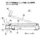
図1は従来の大容量電池パック10を示す。大容量電池パック10は、携帯型のパソコン20の本体部21の手前側の凹状部22に嵌合して、図2に示すように、装着される。大容量電池パック10の上面11は平面である。大容量電池パック10のうち、符号12で示す部分が、装着された状態で、本体部21の前側壁23から手前側に張り出す。25は本体部21に対して開閉可能である液晶表示部である。パソコン20を使用する場合には、操作者は、指先部30で液晶表示部25の先端部26を引っ掛けて引き上げて、液晶表示部25を開く操作を行う。
【0005】
【発明が解決しようとする課題】
大容量電池パック10のうち本体部21の前側壁23から手前側に張り出した張り出し部分12が、指先部30を液晶表示部25の先端部26に引っ掛かり難くしていた。
【0006】
このため、液晶表示部25を開く操作がし難く、場合によっては、爪を傷めたりする虞れもあった。
【0007】
そこで、本発明は、上記課題を解決した携帯型情報処理装置を提供することを目的とする。
【0008】
【課題を解決するための手段】
請求項1の発明は、情報を処理する情報処理部を有する本体部及び該本体部の奥方の軸支部によって前記本体部に対して開閉可能である表示部と、前記本体部の手前側の電池パック装着部に装着された電池パックとの組み合わせをもつ携帯型情報処理装置において、
前記本体部の前記電池パック装着部は、前記本体部の手前側の面に凹状とされた形状であり、
前記電池パックは、上面に凹み部を有する形状であり、該上面の全体が露出した状態で前記電池パック装着部に装着され、
前記電池パックが前記電池パック装着部に装着されている状態で、前記凹み部は、閉じられた前記表示部の先端部に対向する位置に存在する構成としたものである。
【0009】
操作者が手の指先で表示部の端を引っ掛けて引き上げて表示部を開こうとする場合に、凹み部が指先の一部を受け入れ、指先が閉じている表示部の端に引っ掛かり易くなる。
【0010】
請求項2の発明は、請求項1記載の携帯型情報処理装置において、
前記電池パックは、複数の電池がハウジング内に収容してある構成であるようにしたものである。
【0011】
請求項3の発明は、請求項1記載の携帯型情報処理装置において、
前記電池パックの上面の凹み部は、該電池パックの全長に亘って形成してあるようにしたものである。
【0012】
凹み部が電池パックの全長に亘って形成してあることによって、表示部を開こうとする場合に、操作者が指先を閉じている表示部の端の長手方向上どの位置にあてがっても指先は凹み部内に入り、指先が表示部の端に引っ掛かり易くなる。
【0013】
請求項4の発明は、請求項1記載の携帯型情報処理装置において、
前記電池パックは、円柱形状の電池が2列に並んでハウジング内に内蔵してあり、
該ハウジングは、円柱形状の電池の外形に沿う形状を有し、一の電池列を収容する部分と別の電池列とを収容する部分との間の位置に、上記凹み部が形成してある構成としたものである。
【0014】
凹み部は、電池の円柱形状を利用して形成されており、電池の収容部を無理やりに狭く設計することなく、合理的に形成される。
【0017】
【発明の実施の形態】
図3(A)、(B)は本発明の一実施例になる大容量電池パック40を示す。この大容量電池パック40は、図2乃至図6に示すように携帯型のパソコン60に装着されて使用される。Y1が奥方、Y2が手前側、X1−X2が幅方向、Z1が上向、Z2が下方である。
【0018】
携帯型のパソコン60は、図4及び図5に示すように、本体部61と、本体部61の奥方の軸支部63によって本体部61に対して開閉可能に支持されている液晶表示部64とを有する。液晶表示部64は、本体部61上に倒されて閉じた状態と起こされて開いた状態とをとり、その液晶表示面65は、閉じた状態では隠され、開いた状態では露出する。本体部61は、内部に情報処理部としてのCPU等を有し、上面にキーボード部66を有する。本体部61の手前側には、標準の電池パック80又は大容量電池パック40を装着するための電池パック装着部67が形成してある。電池パック装着部67は、本体部61の手前側の面68に対して凹状に形成してあり、この凹状部のサイズは標準電池パック80のサイズと同じである。標準電池パック80は電池パック装着部67の凹部69に丁度収まって装着される。
【0019】
また、液晶表示部64が閉じた状態で、Z1側から見て、液晶表示部64の先端部69が、本体部61の手前側の面68と一致している。
【0020】
次に、大容量電池パック40について説明する。
【0021】
大容量電池パック40は、図3(A)、(B)に示すように、ハウジング41内に円柱形状の電池42、43が3個づつ2列に並んで内蔵してあり、Y1側の面の中央にコネクタ44を有する構成である。45は上面、46は下面である。
【0022】
なお、本実施例では、円柱形状の複数の電池からなる電池パックを例示しているが、請求項1及び請求項3に記載の発明にあっては、電池パックの外観が重要であり、その内部の具体的な構成は本実施例のものに限られない。
【0023】
47は第1の電池列であり、X1−X2に整列している複数電池42よりなる。48は第2の電池列であり、第1の電池列47のY2側に隣接した位置にあり、X1−X2に整列している複数電池43よりなる。ハウジング41は、第1の電池列47を収容する第1の電池列収容部49と第2の電池列収容部48を収容する第2の電池列収容部50がY1−Y2方向上隣接して配置してある構成である。大容量電池パック40は、標準電池パック60に比べて、第2の電池列収容部50の分、サイズが大きい。第2の電池列収容部50は、第1の電池列収容部49よりX1−X2方向の長さが長く、第2の電池列収容部50の両端は、第1の電池列収容部49の両側から突き出している。
【0024】
ハウジング41は電池の形状に沿う形状を有しており、第1の電池列収容部49は、Y1側に円筒の一部の形状を有し、第2の電池列収容部50は略円筒である。上面45には、第1の電池列収容部49と第2の電池列収容部50との間に、X1−X2の全長に亘る凹み部としての溝部51を有する。下面46にも、第1の電池列収容部49と第2の電池列収容部50との間に、X1−X2の全長に亘る溝部52を有する。
【0025】
上記形状の大容量電池パック40は、図5及び図6に示すように、電池パック装着部67に装着してある。第1の電池列収容部49が凹部69に収まっており、第2の電池列収容部50は、本体部61の手前側の面68からY2方向に突き出しており、且つ、Z1側から見て、閉じた状態の液晶表示部64の先端部69からY2方向に突き出している。また、液晶表示部64が閉じた状態で、溝部51は、液晶表示部64の先端部69に対向する位置に位置している。
【0026】
液晶表示部64の先端部69に対向する位置に溝部51が存在するために、パソコン60を使用するに際して、操作者が指先部30で液晶表示部64の先端部69を引っ掛けて引き上げて液晶表示部64を開く操作を行うときに、図6に示すように、指先部30が溝部51内に入って液晶表示部64の先端部69に引っ掛かり易くなり、液晶表示部64を開く操作を、円滑に行うことが可能となる。また、指先を液晶表示部64と大容量電池パック40の間にこじ入れる等の動作を行う必要は無くなり、よって、爪を傷める危険も無くなる。
【0027】
なお、上記の溝部51に似た凹部をX1−X2方向上の一部に形成した場合には、操作者は指先部30を凹部が形成されている個所を意識してあてがう必要がある。しかし、上記の溝部51はX1−X2方向上の全長に亘っているため、操作者は溝部51が形成してある位置を特別に意識しないで液晶表示部64の先端部69のX1−X2方向上、そのときに操作し易い個所に指先を伸ばして当てれば足り、即ち、指先部30を当てる位置に制限はなく、液晶表示部64を開く操作について、パソコン60は良好な操作性を有する。
【0028】
また、大容量電池パック40をパソコン60から取り外す操作は、大容量電池パック40の下面46のロック解除釦を操作しつつ、図5に示すように、手の指先を溝部51と溝部52とに入れて手で第2の電池列収容部50を掴んでY2方向に引くことによって、操作性良く、且つ、大容量電池パック40を落とす危険が少ない状態で行われる。
【0029】
なお本発明の電池パックは、標準よりも大容量を有するものであることに限定されるものではなく、本体部61の電池パック装着部67に装着された状態では、本体部より手前側に張り出す部分が形成される形状を有するものであれば本発明の構造を適用可能である。
【0030】
【発明の効果】
以上説明したように、請求項1の発明は、情報を処理する情報処理部を有する本体部及び該本体部の奥方の軸支部によって前記本体部に対して開閉可能である表示部と、前記本体部の手前側の電池パック装着部に装着された電池パックとの組み合わせをもつ携帯型情報処理装置において、前記本体部の前記電池パック装着部は、前記本体部の手前側の面に凹状とされた形状であり、前記電池パックは、上面に凹み部を有する形状であり、該上面の全体が露出した状態で前記電池パック装着部に装着され、前記電池パックが前記電池パック装着部に装着されている状態で、前記凹み部は、閉じられた前記表示部の先端部に対向する位置に存在する構成としたものであるため、操作者が手の指先で表示部の端を引っ掛けて引き上げて表示部を開こうとする場合に、凹み部が指先の一部を受け入れ、指先が閉じている表示部の端に引っ掛かり易くなり、閉じている表示部を開く操作がし易くなり、また、表示部を開く際に爪を傷めたりする虞れが無くなるように出来る。
【0031】
請求項3の発明は、請求項1記載の電池パックは、凹み部が電池パックの全長に亘って形成してあるようにしたものであるため、表示部を開こうとする場合に、操作者が指先を閉じている表示部の端の長手方向上どの位置にあてがっても指先は凹み部内に入り、指先が表示部の端に引っ掛かり易くなり、操作者は溝部が形成してある位置を特別に意識しないで表示部の端部のうち操作し易い個所に指先を伸ばして当てれば足り、携帯型パソコンは表示部を開く操作について良好な操作性を有する。
【0032】
請求項4の発明は、請求項2記載の電池パックにおいて、円柱形状の電池が2列に並んで内蔵してあり、ハウジングは、円柱形状の電池の外形に沿う形状を有し、上記凹み部は、一の電池列を収容する部分と別の電池列とを収容する部分との間の位置に形成されている構成としたものであるため、凹み部を電池の収容部を無理やりに狭く設計することなく合理的に形成することが出来る。
【図面の簡単な説明】
【図1】従来の大容量電池パックを示す図である。
【図2】図1の大容量電池パックが装着された携帯型パソコンを示す図である。
【図3】本発明の一実施例の大容量電池パックを示す図である。
【図4】図3の大容量電池パックを携帯型パソコンと対応させて示す図である。
【図5】図3の大容量電池パックが装着された携帯型パソコンを示す図である。
【図6】液晶表示部を開くときの操作を示す図である。
【符号の説明】
40 大容量電池パック
42、43 電池
45 上面、
46 下面
47 第1の電池列
48 第2の電池列
49 第1の電池列収容部
50 第2の電池列収容部
51,52 溝部
60 携帯型のパソコン
61 本体部
64 液晶表示部
67 電池パック装着部
69 凹部[0001]
BACKGROUND OF THE INVENTION
The present invention relates to a portableinformation processing apparatus .
[0002]
A portable personal computer operates using a battery pack mounted on the front side as a power source. A concave battery pack mounting portion is formed on the front side of the main body portion of the personal computer, and the battery pack is mounted on the battery pack mounting portion and fits within the outer shape of the main body portion.
[0003]
As a battery pack, a battery pack having a larger capacity than usual is prepared as an option. This large-capacity battery pack is larger in size than a normal battery pack, and in a state where the large-capacity battery pack is mounted on the battery pack mounting portion of the main body, a portion is formed that protrudes to the near side from the main body.
[0004]
[Prior art]
FIG. 1 shows a conventional large-
[0005]
[Problems to be solved by the invention]
In the large-
[0006]
For this reason, it is difficult to open the liquid
[0007]
Accordingly, an object of the present invention is to provide a portableinformation processing apparatus that solves the above-described problems.
[0008]
[Means for Solving the Problems]
The invention according to
The battery pack attachment portion of the main body portion has a shape which isconcave shapedin the plane of thefront side of the main body portion,
The battery pack has a shape having a recess on the upper surface, and is mounted on the battery pack mounting portion with the entire upper surface exposed.
In the state where the battery pack is mounted on the battery pack mounting portion, the dent portion is configured to exist at a position facing the front end portion of the closed display portion.
[0009]
When the operator tries to open the display unit by hooking and lifting the end of the display unit with the fingertip of the hand, the dent portion accepts a part of the fingertip, and the fingertip is easily caught on the end of the display unit.
[0010]
The invention according to
The battery pack is configured such that a plurality of batteries are accommodated in a housing.
[0011]
The invention according to claim 3 is theportable information processing device according to
Recessed portionof the upper surface of the battery pack is obtained as is formed over the entire length ofthe battery pack.
[0012]
Since the dent is formed over the entire length of the battery pack, when the display part is opened, the fingertip can be placed at any position on the end of the display part where the operator closes the fingertip. Enters the recess, and the fingertip is easily caught on the edge of the display unit.
[0013]
A fourth aspect of the present invention is theportable information processing device according to the first aspect,
In the battery pack, cylindrical batteries are arranged in two rowsand incorporated in thehousing ,
該Ha Ujingu mayhave a shape along the outer shape of the batterycylindrical,at aposition between the portion housing portion that housesone of the battery string and the another cellcolumn, the recess is formed It has a certain configuration.
[0014]
The recess is formed by utilizing the cylindrical shape of the battery, and can be reasonably formed without forcibly designing the battery accommodating portion to be narrow.
[0017]
DETAILED DESCRIPTION OF THE INVENTION
3A and 3B show a large-
[0018]
As shown in FIGS. 4 and 5, the portable
[0019]
In addition, when the liquid
[0020]
Next, the large
[0021]
As shown in FIGS. 3 (A) and 3 (B), the large-
[0022]
In the present embodiment, a battery pack composed of a plurality of cylindrical batteries is illustrated, but in the inventions according to
[0023]
[0024]
The
[0025]
The large-
[0026]
Since the
[0027]
Incidentally, in the case of forminga concave portion similar to the above-mentioned
[0028]
Further, the operation of removing the large-
[0029]
The battery pack of the present invention is not limited to having a larger capacity than the standard, and in a state where the battery pack is mounted on the battery
[0030]
【The invention's effect】
As described above, the invention of
[0031]
The invention according to claim 3, since the battery pack according to
[0032]
According to a fourth aspect of the present invention, in the battery pack according to the second aspect of the present invention, the cylindrical batteries are incorporated in two rows, and the housing has a shape that follows the outer shape of the cylindrical battery. Is designed to be formed in a position between the part that accommodates one battery row and the part that accommodates another battery row. Can be reasonably formed without.
[Brief description of the drawings]
FIG. 1 is a diagram showing a conventional large-capacity battery pack.
2 is a diagram showing a portable personal computer equipped with the large-capacity battery pack of FIG. 1;
FIG. 3 is a diagram showing a large-capacity battery pack according to an embodiment of the present invention.
4 is a diagram showing the large-capacity battery pack of FIG. 3 in association with a portable personal computer.
5 is a diagram showing a portable personal computer equipped with the large-capacity battery pack of FIG. 3;
FIG. 6 is a diagram illustrating an operation for opening a liquid crystal display unit.
[Explanation of symbols]
40 large-capacity battery packs 42, 43,
46
Claims (4)
Translated fromJapanese前記本体部の前記電池パック装着部は、前記本体部の手前側の面に凹状とされた形状であり、
前記電池パックは、上面に凹み部を有する形状であり、該上面の全体が露出した状態で前記電池パック装着部に装着され、
前記電池パックが前記電池パック装着部に装着されている状態で、前記凹み部は、閉じられた前記表示部の先端部に対向する位置に存在することを特徴とする携帯型情報処理装置。A main body having an information processing section for processing information, a display section that can be opened and closed with respect to the main body bya shaftsupport section at the back of the main body, and a battery pack mounting sectionon thefront side of the main body. In a portable information processing device having a combination with a battery pack,
The battery pack attachment portion of the main body portion has a shape which isconcave shapedin the plane of thefront side of the main body portion,
The battery pack has a shape having a recess on the upper surface, and is mounted on the battery pack mounting portion with the entire upper surface exposed.
In the state where the battery pack is mounted on the battery pack mounting portion, the recessed portion is present at a position facing the front end portion of the closed display portion.
前記電池パックは、複数の電池がハウジング内に収容してある構成であることを特徴とする携帯型情報処理装置。The portable information processing device according to claim 1,
The battery pack has a configuration in which a plurality of batteries are housed in a housing.
前記電池パックの上面の凹み部は、該電池パックの全長に亘って形成してあることを特徴とする携帯型情報処理装置。The portable information processing device according to claim 1,
The portable information processing apparatus, wherein the recess on the upper surface of the battery pack is formed over the entire length of the battery pack.
前記電池パックは、円柱形状の電池が2列に並んでハウジング内に内蔵してあり、
該ハウジングは、円柱形状の電池の外形に沿う形状を有し、一の電池列を収容する部分と別の電池列とを収容する部分との間の位置に、上記凹み部が形成してある構成としたことを特徴とする携帯型情報処理装置。The portable information processing device according to claim 1,
In the battery pack, cylindrical batteries are arranged in two rows and incorporated in the housing,
The housing has a shape that follows the outer shape of the cylindrical battery, and the recess is formed at a position between a portion that accommodates one battery row and a portion that accommodates another battery row. A portable information processing apparatus characterized by having a configuration.
Priority Applications (7)
| Application Number | Priority Date | Filing Date | Title |
|---|---|---|---|
| JP2001283800AJP4351407B2 (en) | 2001-09-18 | 2001-09-18 | Portable information processing device |
| US10/087,790US6795305B2 (en) | 2001-09-18 | 2002-03-05 | Battery pack for an information processing apparatus and the information processing apparatus |
| DE60220002TDE60220002T2 (en) | 2001-09-18 | 2002-03-07 | A battery pack for an information processing apparatus and the information processing apparatus |
| EP02251603AEP1293879B1 (en) | 2001-09-18 | 2002-03-07 | A battery pack for an information processing apparatus and the information processing apparatus |
| KR1020020016431AKR100799635B1 (en) | 2001-09-18 | 2002-03-26 | Battery pack and information processing device for information processing apparatus |
| CN02108735ACN1405654A (en) | 2001-09-18 | 2002-03-29 | Battery case for information processing device and information processing device |
| CN200910165762ACN101655722A (en) | 2001-09-18 | 2002-03-29 | A battery pack for an information processing apparatus and the information processing apparatus |
Applications Claiming Priority (1)
| Application Number | Priority Date | Filing Date | Title |
|---|---|---|---|
| JP2001283800AJP4351407B2 (en) | 2001-09-18 | 2001-09-18 | Portable information processing device |
Publications (2)
| Publication Number | Publication Date |
|---|---|
| JP2003091339A JP2003091339A (en) | 2003-03-28 |
| JP4351407B2true JP4351407B2 (en) | 2009-10-28 |
Family
ID=19107246
Family Applications (1)
| Application Number | Title | Priority Date | Filing Date |
|---|---|---|---|
| JP2001283800AExpired - Fee RelatedJP4351407B2 (en) | 2001-09-18 | 2001-09-18 | Portable information processing device |
Country Status (6)
| Country | Link |
|---|---|
| US (1) | US6795305B2 (en) |
| EP (1) | EP1293879B1 (en) |
| JP (1) | JP4351407B2 (en) |
| KR (1) | KR100799635B1 (en) |
| CN (2) | CN1405654A (en) |
| DE (1) | DE60220002T2 (en) |
Families Citing this family (14)
| Publication number | Priority date | Publication date | Assignee | Title |
|---|---|---|---|---|
| JPWO2004066131A1 (en)* | 2003-01-17 | 2006-05-18 | 富士通株式会社 | Information processing device |
| JP2005157789A (en)* | 2003-11-26 | 2005-06-16 | Toshiba Corp | Electronics |
| TWI254475B (en)* | 2004-12-17 | 2006-05-01 | Mitac Technology Corp | Battery module with plugging and expanding |
| TWI335499B (en) | 2004-12-29 | 2011-01-01 | Asustek Comp Inc | Notebook computer and battery device thereof |
| JP4686221B2 (en)* | 2005-03-17 | 2011-05-25 | 株式会社東芝 | Electronics |
| CN100367154C (en)* | 2005-04-07 | 2008-02-06 | 华硕电脑股份有限公司 | Notebook computer and battery device thereof |
| JP2007058579A (en) | 2005-08-24 | 2007-03-08 | Fujitsu Ltd | Electronics |
| US20070091556A1 (en)* | 2005-10-20 | 2007-04-26 | Inventec Corporation | Module assembly for locking and unlocking a battery of an electronic device |
| JP2008112328A (en)* | 2006-10-31 | 2008-05-15 | Sony Corp | Information processor |
| TWM357642U (en)* | 2009-01-21 | 2009-05-21 | Quanta Comp Inc | Thin notebook computer |
| TWM357643U (en)* | 2009-01-21 | 2009-05-21 | Quanta Comp Inc | Thin notebook computer |
| CN102076200B (en)* | 2009-11-24 | 2014-11-05 | 鸿富锦精密工业(深圳)有限公司 | Electronic equipment |
| JP5895509B2 (en)* | 2011-12-20 | 2016-03-30 | 富士通株式会社 | Electronics |
| USD1049027S1 (en)* | 2022-11-09 | 2024-10-29 | Shenzhen south China yingcai technology co. LTD | Wireless charger |
Family Cites Families (37)
| Publication number | Priority date | Publication date | Assignee | Title |
|---|---|---|---|---|
| FR2519804A1 (en)* | 1982-01-14 | 1983-07-18 | Accumulateurs Fixes | ELECTROCHEMICAL GENERATOR BATTERY BOX |
| US5060990A (en)* | 1991-02-08 | 1991-10-29 | Hewlett-Packard Company | Multi-stage door snap |
| JPH05143192A (en) | 1991-11-22 | 1993-06-11 | Sharp Corp | Notebook type computer device |
| JP3215231B2 (en)* | 1993-07-26 | 2001-10-02 | 株式会社東芝 | Portable information processing device |
| JP3054306B2 (en)* | 1994-02-04 | 2000-06-19 | キヤノン株式会社 | Notebook PC and battery case |
| US5583744A (en)* | 1994-09-06 | 1996-12-10 | Citizen Watch Co., Ltd. | Portable computer with detachable battery pack |
| US5594617A (en)* | 1994-12-06 | 1997-01-14 | Digital Equipment Corporation | Rotating battery hinge for a notebook computer |
| JPH09230961A (en)* | 1996-02-27 | 1997-09-05 | Toshiba Corp | Portable electronic devices |
| US5724224A (en)* | 1996-10-21 | 1998-03-03 | Dell Usa, L.P. | Integrated palm rest and battery pack having first and second palm rest surfaces defining a pair of adjacent arcuate surfaces in a portable computer system |
| JPH10222259A (en)* | 1997-01-31 | 1998-08-21 | Citizen Watch Co Ltd | Portable computer equipped with battery pack |
| US6002583A (en)* | 1997-01-31 | 1999-12-14 | Citizen Watch Co., Ltd. | Portable computer provided with removable battery pack |
| US6493178B1 (en)* | 1997-04-30 | 2002-12-10 | Spectra Logic Corporation | Data cartridge library system |
| KR19990018618A (en)* | 1997-08-28 | 1999-03-15 | 왕중일 | Extended Battery Pack for Notebook Computers |
| USD406561S (en)* | 1997-10-14 | 1999-03-09 | Sony Corporation | Battery |
| USD415466S (en)* | 1998-05-15 | 1999-10-19 | Sharp Kabushiki Kaisha | Battery for an electronic computer |
| CN2377614Y (en) | 1999-01-25 | 2000-05-10 | 仁宝电脑工业股份有限公司 | Laptops with external battery packs |
| JP3945986B2 (en)* | 1999-03-10 | 2007-07-18 | 富士通株式会社 | Electronics |
| USD448003S1 (en)* | 2001-01-10 | 2001-09-18 | Sony Corporation | Rechargeable battery |
| JP4555521B2 (en)* | 2001-09-18 | 2010-10-06 | 富士通株式会社 | Information processing apparatus and detachable unit |
| US6639751B2 (en)* | 2001-10-19 | 2003-10-28 | Spectra Logic Corporation | Data cartridge library |
| USD476949S1 (en)* | 2002-01-14 | 2003-07-08 | Sony Corporation | Storage battery |
| US7400469B2 (en)* | 2003-09-16 | 2008-07-15 | Spectra Logic Corporation | Magazine-based library |
| US7359142B2 (en)* | 2003-06-26 | 2008-04-15 | Spectra Logic Corporation | Magazine-based data cartridge library |
| US20040264037A1 (en)* | 2003-06-26 | 2004-12-30 | Spectra Logic Corporation | Magazine-Based Data Cartridge Library |
| US20050007692A1 (en)* | 2003-06-26 | 2005-01-13 | Spectra Logic Corporation | Magazine-Based Data Cartridge Library |
| US7154703B2 (en)* | 2003-06-26 | 2006-12-26 | Spectra Logic Corporation | Magazine-based data cartridge library |
| US7265938B2 (en)* | 2003-06-26 | 2007-09-04 | Spectra Logic Corporation | Magazine-based data cartridge library |
| US7180701B2 (en)* | 2003-06-26 | 2007-02-20 | Spectra Logic Corporation | Magazine-based data cartridge library |
| US7508621B2 (en)* | 2003-06-26 | 2009-03-24 | Spectra Logic Corporation | Magazine-based data cartridge library |
| TWI223794B (en)* | 2003-08-25 | 2004-11-11 | Benq Corp | Disc drive |
| US7010387B2 (en)* | 2003-08-28 | 2006-03-07 | Spectra Logic Corporation | Robotic data storage library comprising a virtual port |
| US7177723B2 (en)* | 2003-08-28 | 2007-02-13 | Spectra Logic Corporation | Operational optimization after powering on a robotic data storage library |
| US7102848B2 (en)* | 2004-03-05 | 2006-09-05 | Spectra Logic Corporation | Modular robotics system for a data cartridge library |
| US7119982B2 (en)* | 2004-03-05 | 2006-10-10 | Spectra Logic Corporation | Data cartridge library operable with a multipiece magazine, drive bay, user interface, an entry/exit port, and universal electronics bay |
| US7085097B2 (en)* | 2004-03-05 | 2006-08-01 | Spectra Logic Corporation | Entry/exit port magazine for a data cartridge library |
| US7145747B2 (en)* | 2004-03-05 | 2006-12-05 | Spectra Logic Corporation | Data cartridge library including a magazine, a picker, an elevator, and a grasper |
| US7130947B2 (en)* | 2004-04-29 | 2006-10-31 | International Business Machines Corporation | Method of arbitration which allows requestors from multiple frequency domains |
- 2001
- 2001-09-18JPJP2001283800Apatent/JP4351407B2/ennot_activeExpired - Fee Related
- 2002
- 2002-03-05USUS10/087,790patent/US6795305B2/ennot_activeExpired - Lifetime
- 2002-03-07EPEP02251603Apatent/EP1293879B1/ennot_activeExpired - Lifetime
- 2002-03-07DEDE60220002Tpatent/DE60220002T2/ennot_activeExpired - Lifetime
- 2002-03-26KRKR1020020016431Apatent/KR100799635B1/ennot_activeExpired - Fee Related
- 2002-03-29CNCN02108735Apatent/CN1405654A/enactivePending
- 2002-03-29CNCN200910165762Apatent/CN101655722A/enactivePending
Also Published As
| Publication number | Publication date |
|---|---|
| DE60220002T2 (en) | 2008-02-21 |
| US20030053290A1 (en) | 2003-03-20 |
| EP1293879A2 (en) | 2003-03-19 |
| KR100799635B1 (en) | 2008-01-30 |
| EP1293879A3 (en) | 2005-09-07 |
| DE60220002D1 (en) | 2007-06-21 |
| KR20030024546A (en) | 2003-03-26 |
| EP1293879B1 (en) | 2007-05-09 |
| CN1405654A (en) | 2003-03-26 |
| CN101655722A (en) | 2010-02-24 |
| US6795305B2 (en) | 2004-09-21 |
| JP2003091339A (en) | 2003-03-28 |
Similar Documents
| Publication | Publication Date | Title |
|---|---|---|
| JP4351407B2 (en) | Portable information processing device | |
| US5677827A (en) | Notebook type personal computer and battery case | |
| US6347796B1 (en) | Hand held video game case with universal power pack | |
| JP2002134951A (en) | Electronics | |
| JPH09230961A (en) | Portable electronic devices | |
| JP4555521B2 (en) | Information processing apparatus and detachable unit | |
| JPH10307640A (en) | Portable information devices | |
| JP2011071002A (en) | Information processing device | |
| US7203059B1 (en) | Ergonomic portable computer | |
| CN113095100B (en) | Portable Terminal | |
| JP2004214969A (en) | Portable electronic devices | |
| CN109286699B (en) | Portable terminal, imaging device, and reading device | |
| CN201331655Y (en) | Battery cover module | |
| CN215377283U (en) | A mechanical keyboard with a flip type dust protection cover | |
| JP2001029686A (en) | Washing machine lid | |
| JP4058800B2 (en) | Portable information processing device | |
| JP5218444B2 (en) | Information processing apparatus and detachable unit | |
| JP2003167643A (en) | Computer device | |
| JP2003031195A (en) | Electronics | |
| JP4322356B2 (en) | Small electronic equipment | |
| KR19990004441A (en) | Portable computer | |
| JPH09297633A (en) | Electronics | |
| JPWO2004027701A1 (en) | Portable IC card reader and method of using the same | |
| KR20040021280A (en) | Mouse for computer | |
| JP3030937U (en) | Communication terminal housing case |
Legal Events
| Date | Code | Title | Description |
|---|---|---|---|
| A621 | Written request for application examination | Free format text:JAPANESE INTERMEDIATE CODE: A621 Effective date:20061013 | |
| A131 | Notification of reasons for refusal | Free format text:JAPANESE INTERMEDIATE CODE: A131 Effective date:20090127 | |
| A521 | Request for written amendment filed | Free format text:JAPANESE INTERMEDIATE CODE: A523 Effective date:20090327 | |
| A131 | Notification of reasons for refusal | Free format text:JAPANESE INTERMEDIATE CODE: A131 Effective date:20090421 | |
| A521 | Request for written amendment filed | Free format text:JAPANESE INTERMEDIATE CODE: A523 Effective date:20090619 | |
| TRDD | Decision of grant or rejection written | ||
| A01 | Written decision to grant a patent or to grant a registration (utility model) | Free format text:JAPANESE INTERMEDIATE CODE: A01 Effective date:20090714 | |
| A01 | Written decision to grant a patent or to grant a registration (utility model) | Free format text:JAPANESE INTERMEDIATE CODE: A01 | |
| A61 | First payment of annual fees (during grant procedure) | Free format text:JAPANESE INTERMEDIATE CODE: A61 Effective date:20090724 | |
| FPAY | Renewal fee payment (event date is renewal date of database) | Free format text:PAYMENT UNTIL: 20120731 Year of fee payment:3 | |
| R150 | Certificate of patent or registration of utility model | Ref document number:4351407 Country of ref document:JP Free format text:JAPANESE INTERMEDIATE CODE: R150 Free format text:JAPANESE INTERMEDIATE CODE: R150 | |
| FPAY | Renewal fee payment (event date is renewal date of database) | Free format text:PAYMENT UNTIL: 20120731 Year of fee payment:3 | |
| FPAY | Renewal fee payment (event date is renewal date of database) | Free format text:PAYMENT UNTIL: 20130731 Year of fee payment:4 | |
| S111 | Request for change of ownership or part of ownership | Free format text:JAPANESE INTERMEDIATE CODE: R313113 | |
| R350 | Written notification of registration of transfer | Free format text:JAPANESE INTERMEDIATE CODE: R350 | |
| LAPS | Cancellation because of no payment of annual fees |