JP4350310B2 - Balloon catheter for cryotherapy - Google Patents
Balloon catheter for cryotherapyDownload PDFInfo
- Publication number
- JP4350310B2 JP4350310B2JP2000598072AJP2000598072AJP4350310B2JP 4350310 B2JP4350310 B2JP 4350310B2JP 2000598072 AJP2000598072 AJP 2000598072AJP 2000598072 AJP2000598072 AJP 2000598072AJP 4350310 B2JP4350310 B2JP 4350310B2
- Authority
- JP
- Japan
- Prior art keywords
- catheter
- lumen
- balloon
- tissue
- coolant fluid
- Prior art date
- Legal status (The legal status is an assumption and is not a legal conclusion. Google has not performed a legal analysis and makes no representation as to the accuracy of the status listed.)
- Expired - Fee Related
Links
Images


Classifications
- A—HUMAN NECESSITIES
- A61—MEDICAL OR VETERINARY SCIENCE; HYGIENE
- A61M—DEVICES FOR INTRODUCING MEDIA INTO, OR ONTO, THE BODY; DEVICES FOR TRANSDUCING BODY MEDIA OR FOR TAKING MEDIA FROM THE BODY; DEVICES FOR PRODUCING OR ENDING SLEEP OR STUPOR
- A61M25/00—Catheters; Hollow probes
- A61M25/10—Balloon catheters
- A61M25/1011—Multiple balloon catheters
- A—HUMAN NECESSITIES
- A61—MEDICAL OR VETERINARY SCIENCE; HYGIENE
- A61B—DIAGNOSIS; SURGERY; IDENTIFICATION
- A61B18/00—Surgical instruments, devices or methods for transferring non-mechanical forms of energy to or from the body
- A61B18/02—Surgical instruments, devices or methods for transferring non-mechanical forms of energy to or from the body by cooling, e.g. cryogenic techniques
- A—HUMAN NECESSITIES
- A61—MEDICAL OR VETERINARY SCIENCE; HYGIENE
- A61B—DIAGNOSIS; SURGERY; IDENTIFICATION
- A61B17/00—Surgical instruments, devices or methods
- A61B2017/00017—Electrical control of surgical instruments
- A61B2017/00022—Sensing or detecting at the treatment site
- A61B2017/00084—Temperature
- A—HUMAN NECESSITIES
- A61—MEDICAL OR VETERINARY SCIENCE; HYGIENE
- A61B—DIAGNOSIS; SURGERY; IDENTIFICATION
- A61B17/00—Surgical instruments, devices or methods
- A61B17/22—Implements for squeezing-off ulcers or the like on inner organs of the body; Implements for scraping-out cavities of body organs, e.g. bones; for invasive removal or destruction of calculus using mechanical vibrations; for removing obstructions in blood vessels, not otherwise provided for
- A61B2017/22051—Implements for squeezing-off ulcers or the like on inner organs of the body; Implements for scraping-out cavities of body organs, e.g. bones; for invasive removal or destruction of calculus using mechanical vibrations; for removing obstructions in blood vessels, not otherwise provided for with an inflatable part, e.g. balloon, for positioning, blocking, or immobilisation
- A61B2017/22054—Implements for squeezing-off ulcers or the like on inner organs of the body; Implements for scraping-out cavities of body organs, e.g. bones; for invasive removal or destruction of calculus using mechanical vibrations; for removing obstructions in blood vessels, not otherwise provided for with an inflatable part, e.g. balloon, for positioning, blocking, or immobilisation with two balloons
- A—HUMAN NECESSITIES
- A61—MEDICAL OR VETERINARY SCIENCE; HYGIENE
- A61B—DIAGNOSIS; SURGERY; IDENTIFICATION
- A61B18/00—Surgical instruments, devices or methods for transferring non-mechanical forms of energy to or from the body
- A61B2018/00053—Mechanical features of the instrument of device
- A61B2018/00214—Expandable means emitting energy, e.g. by elements carried thereon
- A61B2018/0022—Balloons
- A—HUMAN NECESSITIES
- A61—MEDICAL OR VETERINARY SCIENCE; HYGIENE
- A61B—DIAGNOSIS; SURGERY; IDENTIFICATION
- A61B18/00—Surgical instruments, devices or methods for transferring non-mechanical forms of energy to or from the body
- A61B18/02—Surgical instruments, devices or methods for transferring non-mechanical forms of energy to or from the body by cooling, e.g. cryogenic techniques
- A61B2018/0212—Surgical instruments, devices or methods for transferring non-mechanical forms of energy to or from the body by cooling, e.g. cryogenic techniques using an instrument inserted into a body lumen, e.g. catheter
- A—HUMAN NECESSITIES
- A61—MEDICAL OR VETERINARY SCIENCE; HYGIENE
- A61F—FILTERS IMPLANTABLE INTO BLOOD VESSELS; PROSTHESES; DEVICES PROVIDING PATENCY TO, OR PREVENTING COLLAPSING OF, TUBULAR STRUCTURES OF THE BODY, e.g. STENTS; ORTHOPAEDIC, NURSING OR CONTRACEPTIVE DEVICES; FOMENTATION; TREATMENT OR PROTECTION OF EYES OR EARS; BANDAGES, DRESSINGS OR ABSORBENT PADS; FIRST-AID KITS
- A61F7/00—Heating or cooling appliances for medical or therapeutic treatment of the human body
- A61F7/12—Devices for heating or cooling internal body cavities
- A61F7/123—Devices for heating or cooling internal body cavities using a flexible balloon containing the thermal element
- A—HUMAN NECESSITIES
- A61—MEDICAL OR VETERINARY SCIENCE; HYGIENE
- A61M—DEVICES FOR INTRODUCING MEDIA INTO, OR ONTO, THE BODY; DEVICES FOR TRANSDUCING BODY MEDIA OR FOR TAKING MEDIA FROM THE BODY; DEVICES FOR PRODUCING OR ENDING SLEEP OR STUPOR
- A61M25/00—Catheters; Hollow probes
- A61M25/10—Balloon catheters
- A61M25/1011—Multiple balloon catheters
- A61M2025/1013—Multiple balloon catheters with concentrically mounted balloons, e.g. being independently inflatable
- A—HUMAN NECESSITIES
- A61—MEDICAL OR VETERINARY SCIENCE; HYGIENE
- A61M—DEVICES FOR INTRODUCING MEDIA INTO, OR ONTO, THE BODY; DEVICES FOR TRANSDUCING BODY MEDIA OR FOR TAKING MEDIA FROM THE BODY; DEVICES FOR PRODUCING OR ENDING SLEEP OR STUPOR
- A61M25/00—Catheters; Hollow probes
- A61M25/10—Balloon catheters
- A61M2025/1043—Balloon catheters with special features or adapted for special applications
- A61M2025/1081—Balloon catheters with special features or adapted for special applications having sheaths or the like for covering the balloon but not forming a permanent part of the balloon, e.g. retractable, dissolvable or tearable sheaths
- A—HUMAN NECESSITIES
- A61—MEDICAL OR VETERINARY SCIENCE; HYGIENE
- A61M—DEVICES FOR INTRODUCING MEDIA INTO, OR ONTO, THE BODY; DEVICES FOR TRANSDUCING BODY MEDIA OR FOR TAKING MEDIA FROM THE BODY; DEVICES FOR PRODUCING OR ENDING SLEEP OR STUPOR
- A61M2205/00—General characteristics of the apparatus
- A61M2205/36—General characteristics of the apparatus related to heating or cooling
- A61M2205/3606—General characteristics of the apparatus related to heating or cooling cooled
Landscapes
- Health & Medical Sciences (AREA)
- Life Sciences & Earth Sciences (AREA)
- Surgery (AREA)
- Heart & Thoracic Surgery (AREA)
- Animal Behavior & Ethology (AREA)
- General Health & Medical Sciences (AREA)
- Engineering & Computer Science (AREA)
- Nuclear Medicine, Radiotherapy & Molecular Imaging (AREA)
- Biomedical Technology (AREA)
- Veterinary Medicine (AREA)
- Public Health (AREA)
- Hematology (AREA)
- Biophysics (AREA)
- Pulmonology (AREA)
- Anesthesiology (AREA)
- Child & Adolescent Psychology (AREA)
- Otolaryngology (AREA)
- Medical Informatics (AREA)
- Molecular Biology (AREA)
- Media Introduction/Drainage Providing Device (AREA)
- Thermotherapy And Cooling Therapy Devices (AREA)
Abstract
Description
Translated fromJapanese【0001】
【発明の属する技術分野】
本発明は組織再建または組織増殖を抑制または排除するための装置および方法に関するものであり、特に、寒冷療法用のバルーンカテーテルに関連している。
【0002】
【従来の技術】
治療目的で低温を利用する寒冷療法は医療分野では周知である。寒冷療法をうまく定義した応用例の幾つかとして下記のものが挙げられる。
(1) 牛、ブタ、または、羊から収集した組織を低温で保存して、組織に存在している弾性膜組織すなわちエラスチンを後の適用に備えて保護する。かかる温度低下を利用しなければ、組織は乾燥し、元の力学的特性、物理的特性、化学的特性を喪失してしまう。
(2) 心臓切開手術の間、心臓を切開して心臓弁を取り替える場合も、下を走る罹病した冠動脈を置換する場合も、いずれも、心臓を包囲している心筋または組織を氷またはサブクール液に浸すことにより心筋または周囲組織を低温に付しながら、手術を進行させながら心筋または周囲組織を保存する。
【0003】
(3) 心臓切開手術の間、大動脈を十字鉗子で締めて心臓からの血液を人工心肺装置内へ方向づけた場合には、血液は低温の心停止溶液と混合されてセルとその他の血中必須成分とを保存し、外科手術が長期化する場合には、特に重要な処置手順となる。
(4) 低温ベースの溶液中で低温環境に保存された牛の心臓弁および他の同種移植片の心臓便は、機械的な双小葉式の心臓弁または単小葉式の心臓弁と比較した場合には、長期の追跡調査の間もより優れた性能を有していることが分かってきた。
(5) 大半の痛み抑制治療の状況で、激痛のエリアすなわち領域を低温の流体すなわち「低温パック」に晒して、神経損傷を低減するとともに痛みを和らげている。
【0004】
本発明は、バルーン脈管形成術またはステント移植の後で、寒冷療法を利用して組織損傷を低減することを目的としている。脈管形成術またはステント移植が失敗する最もありふれた原因の1つが再狭窄である。先の閉塞部位の心臓壁の組織の内植および/または弾性反跳のせいで動脈が再度閉塞した場合には再狭窄と明証される。バルーン脈管形成処置手順またはステント移植処置手順が完了した後で、動脈の壁の細胞性層を押圧してバルーンカテーテルを膨張させるために必要な力を使うせいで動脈壁が損傷または炎症を呈することが多い。特に、動脈が閉塞した病巣の部位でバルーンを膨張させた場合には、バルーンが膨張するために病巣に作用する力によって病巣が力学的に押し上げられる。ブタおよび羊について実験の病理から、バルーンの膨張が病巣の部位の内皮の損傷はもとより組織移動の原因ともなっているのが明らかになっている。かかる損傷は、血液やある種のトロンビン(凝固物質)が充満した内部管腔壁の割れ目を特徴とする。これらの割れ目は、動脈の伸展性のもとであるコラーゲン、平滑筋細胞、および、弾性細胞を主成分とする動脈血管外膜および中膜と呼ばれる血管壁の第2層および第3層に浸透する可能性がある。
【0005】
上記の各層がバルーンの膨張またはステントの移植を原因として破損した場合は、伸展性反応が失われる。この結果、時間の経過とともに細胞が増殖する。増殖は動脈壁に損傷が加わった直後に始まるが、最大の増殖は最初に損傷が起こってから6ヶ月ないし18ヶ月の間であることを観察することができる。
【0006】
本発明はまた、組織の再建または増殖を抑制または排除する必要がある臨床場面で寒冷療法を利用する装置および方法を目的としている。このような臨床場面は血管への適用例または非血管への適用例の場合もあり、また、冠動脈への適用例または非冠動脈への適用例であってもよい。例えば、本発明に従った装置および方法を利用して、脈管形成を終焉させることによって、すなわち、癌性腫瘍の周囲またはその内部の毛細血管および血管からなる血管網の形成を終焉させることによって、癌を治療することができる。
【0007】
【発明の構成】
本発明は、組織の部位における組織の再建または組織の増殖を抑制することを目的としたカテーテルに関連する。このカテーテルは、カテーテルの遠位端に配置された外側バルーンと、外側バルーンと流体連絡状態にあるとともに液体源に流体接続されて、液体を利用して外側バルーンを拡張させて組織の部位と接触させるようにした第1の管腔と、近位端で冷却剤の流体源に流体接続された第2の管腔とを備えており、第2の管腔については、冷却剤の流体を第2の管腔の遠位端へと輸送して、外側バルーンの中の液体を冷却することにより、組織の部位を寒冷療法の温度まで冷却することを目的としている。好ましい実施形態では、開口を通って膨張した後でも、冷却剤の流体温度は液体を凍結させるのに十分なだけ低温である。第2の管腔は開口を備え、この開口は、冷却剤の流体がそこを通過すると膨張して、冷却剤の流体温度を低下させることができるような構成および寸法にされている。
【0008】
外側バルーンは、組織の部位の温度を監視するための温度センサーを備えており、流体冷却剤源と第2の管腔との間にはバルブが存在し、第2の管腔への冷却剤のガスの導入を制御するのが好ましい。
【0009】
カテーテルは、外側バルーンに極めて近接した第2の管腔の遠位端と流体連絡状態にある内側バルーンを備えていてもよい。第2の管腔と内側バルーンとの間の流体連絡は開口を通して行われ、冷却剤の流体が内側バルーン内へと膨張することができるようにする。カテーテルは、ガイドワイヤを受容してカテーテルを組織の部位に方向付けるような構成および寸法に設定した第3の管腔も有している。
【0010】
内側バルーンから冷却剤の流体を除去するのを容易にするために、カテーテルは遠位端で内側バルーンと流体連絡状態にある第4の管腔を備えていてもよい。第4の管腔は真空に流体接続されて、内側バルーンから冷却剤の流体を除去する支援を行うことができる。
【0011】
別な実施形態では、カテーテルは、組織部位へとカテーテルを方向付けるガイドワイヤを受容するような構成および寸法に設定された第1の管腔と、カテーテルの遠位端に配置された外側バルーンと、遠位端で外側バルーンと流体連絡状態になるとともに近位端で媒体源に流体接続されて、媒体を利用して外側バルーンを拡張させ、外側バルーンが組織の部位と接触するようにした第2の管腔とを有している。媒体は、通常は、媒体が組織再建または組織増殖に何ら効果を有していない不活性状態にあるが、エネルギーを添加すると、媒体が組織再建または組織増殖を実施する活性状態に転換され得る。カテーテルはまた、カテーテルの遠位端に配置されるとともに外側バルーンに極めて近接した内側バルーンと、遠位端で内側バルーンと流体連絡状態にあるとともに近位端で活性化要因源に流体接続されて内側バルーンに活性化要因を輸送し、媒体を活性状態に転換するのに必要なエネルギーを供与する第3の管腔とを備えている。
【0012】
活性化要因は光、熱、或いは、他のエネルギー形態であればよい。媒体は、生理食塩水のような耐性が良好な流体を含んでいるのが好ましい。媒体はまた、活性状態で放射性となる物質を含んでいてもよい。
【0013】
本発明はまた、組織の部位で組織再建または組織増殖を抑制する方法にも関連している。この方法は、少なくとも2つの管腔を備えたカテーテルに或る量の低温媒体を流体接続する工程と、カテーテルを患者体内に挿入し、組織の部位にカテーテルを搬送する工程と、遠位端に複数の穴を備えた管腔を通して低温媒体を分配し、組織の部位に低温媒体を搬送する工程と、カテーテルを部位に固着させるために膨張可能なバルーンを設ける工程とを含み、バルーンは外側不浸透性壁と孔を有した内側壁とを備えており、上記方法は、外側壁と内側壁の間で孔を介して低温媒体を搬送する工程を更に含んでいる。
【0014】
低温媒体は14℃より低い温度に維持されるのが好ましい。1つの実施形態では、低温媒体は開口を通過して低温媒体の温度を低下させる。カテーテルは、2つの互いに間隔を設けた、膨張可能で組織の部位の上流側と下流側に位置するバルーンを有していてもよい。カテーテルには、閉じた遠位端を有する通路と孔を有する周辺壁とが設けられて、低温媒体を孔を介して分配できるようにすることができる。
本発明の好ましい特徴は添付の図面に開示されており、図面中では、同一参照記号は複数の図を通して同一要素を示している。
【0015】
【発明の実施の形態】
図1は本発明のシステム全体10の第1の実施形態を示している。システム10は、低温発生装置11、低温貯蔵槽13、低温発生装置11を低温貯蔵槽13と相互接続する導管15、および、貯蔵槽13から把持制御装置19まで低温媒体が流動できるようにする排出導管17とを備えており、把持制御装置19は、入口ポート21、出口ポート23、および、バルブアクチュエータ27を備えたバルブ25を有しており、ユーザの操作によってバルブ25を貫通する流路の計測を可能にして、低温媒体がカテーテル30に流れ込む流速を制御することができるようにしている。バルブ25はどのような所望のタイプのものであってもよいが、一例として、バルブヘッドを閉鎖位置に偏倚させるスプリング26を備え、アクチュエータ27が開放されると、バルブ25が閉鎖位置に復帰するようにしたものが挙げられる。意図した環境、すなわち、低温媒体が−10℃から4℃の間の温度である環境で流れを遮断するために堅固かつ反復的に定位置に着くのであれば、どのような好適なバルブでも採用することができる。かかるバルブは当業者に公知である。
【0016】
図1から更に看破できるように、貯蔵槽13は2つのゲージ、すなわち、温度読出し計14と体積または圧力の表示計16とを備えている。体積表示計16は、当業者に公知の態様で低温媒体の流速を表示することができる。例えば、低温媒体の流路は、制限された開口と、制限された開口の直ぐ上流側と下流側のセンサーラインとを備えた導管を有していてもよい。制限された開口のいずれの側の圧力差も当業者に公知の態様で流速と関連している。
【0017】
図2はカテーテル30の詳細を更に示している。カテーテル30は2つの管腔を備え、第1の管腔31は、所望の位置へカテーテル30を誘導して移動させるように設計されたガイドワイヤ33を通すように設けられており、第2の管腔35は、本明細書中に説明した理由から所望の位置に低温媒体を分配するように設計された所定のパターンと長さのバルーン37および複数のポート39を有している。カテーテル30は、把持制御装置19に接続したハブ38も備えている。
【0018】
図3および図4は、本発明に従った、3つの管腔を備えたカテーテル40の別な実施形態を示している。第1の管腔41は、ガイドワイヤ(図示せず)を挿入できるように設計されたポート42を備えている。第2の管腔43は、バルーン44を挿入できるように設けられている。第3の管腔46は、所望の部位で低温媒体を分配できるように設計された所定のパターンおよび長さの複数の孔45を内部に備えている。
【0019】
図5を参照すると、カテーテル50の別な実施形態はカテーテル40の特徴全てを備えているが、低温媒体を分配することになる部位の上流側に更に別なバルーン51を追加している。開口53は、カテーテル40の開口45に対応しているが、所定のパターンと長さで設けられているとともに、バルーン51とバルーン54の間の領域に配置されている。従って、バルーン51とバルーン54の間の区域はその間隙に、低温媒体を分配することになる隔絶領域を画定している。
【0020】
図6は、内側層63および外側層65を備えたバルーン61を有しているカテーテル60を例示しており、内側層63はそこを貫通する開口64を備えているのが示されている。低温媒体は内側層63と外側層65の間の空間66の中へと方向付けられ、低温媒体がチャンバー67の内部へ分配され得るようにしている。この実施形態では、チャンバー67の内部に低温媒体を分配することにより、低温媒体と治療中の組織とが直接接触することを回避している。しかしながら、内側層63と外側層65を介する熱交換によって、所望の態様で組織を冷却するという同じ効果が得られる。
【0021】
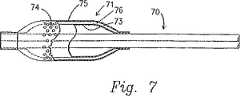
図7は、内側層73および外側層75を備えたバルーン71を有しているカテーテル70を例示している。開口74は外側層75に形成され、低温媒体は層73と層75の間に画定された空間76の中へと方向付けられ、低温媒体を2つの層の間に分配することができるようにし得る。この実施形態では、図6に例示したカテーテル60と対比すると、低温媒体が治療中の組織に直接接触する。
【0022】
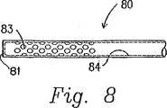
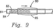
図8は、バルーンは備えていないが閉じた遠位端81を備えたカテーテル80を例示している。カテーテル80の遠位端81に隣接した周辺壁には所望のパターンと長さで多数の孔83が形成されており、カテーテル80の内部通路84を通って媒体の適用の所望部位の位置まで低温媒体を分配できるようにしている。図9では、カテーテル80には、開口83を覆って低温媒体の流れを妨げる可撓性のある弾性鞘部材85が設けられているのが分かる。鞘部材85は当業者には公知の態様で引っぱられて開口部83の覆いを取り除き、所望されるとおりに低温媒体を分配できるようにすることが可能である。
【0023】
上述のように、貯蔵槽13を低温媒体で充満するために、低温媒体は圧縮チャンバーを備えており、このチャンバー内で空気がフレオンまたはヘリウムと混合され、温度が14℃と−10℃の間の範囲になるまで混合気体が圧縮される。水、生理食塩水を混入した水、または、好適な冷却剤と混合した水を空気/フレオン/ヘリウムの混合物の代用とすることもできる。その後、低温媒体は導管15を通ってからバルブ12の開口によって貯蔵タンク13に搬送される。貯蔵タンク13は当業者に公知の態様で隔絶されて、低温媒体の温度を実質的に一定に維持することができるようにし得る。低温媒体は導管17内を搬送されて、バルブ25およびアクチュエータ27を備えた把持制御装置19に至る。オペレータが所望すれば、上述のカテーテルのうちの1つを把持制御装置19の出口ポート23に取り付けることが可能であり、オペレータはアクチュエータ27を作動させてバルブ25の開口の開き具合を多様に変えて、カテーテルを通って所望の位置まで所要の温度で低温媒体を流動させることができる。更に、どのカテーテルも、組織と接触した領域の近辺に位置しているとともに温度計に連結されたサーミスタまたは同様の温度読み取り装置を備え、治療温度を監視することができるようにしてもよい。
【0024】
所望されれば、低温媒体は、抗生物質、抗凝固剤、増殖抑制剤、遺伝子物質など、低温媒体と一緒に管腔内の所望の部位で分配することのできる他の物質(単体または複数)と混合することが可能である。これらの物質は低温発生装置11内の低温媒体、貯蔵槽13内の低温媒体、または、カテーテル内の把持制御装置19の下流側の低温媒体と混合することが可能である。
【0025】
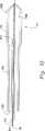
図10は、圧縮装置または他の低温発生装置を使用しなくても寒冷治療用の温度を達成するカテーテル90を例示している。カテーテル90はガイドワイヤ94を挿入するための第1の管腔92を備えている。他の各実施形態の事例と同様に、ガイドワイヤ94は、通常は放射線写真撮像視覚化状態で所望の位置まで方向付けられ、カテーテル90はガイドワイヤを覆って第1の管腔92を通して患者体内に挿入される。カテーテル90は、外側バルーン98と流体導通状態にある第2の管腔を備えている。外側バルーン98は流体を、好ましくは、液体を第2の管腔96に導入することにより膨張させられ、拡張させられる。カテーテル90が挿入されて、外側バルーンが液体で膨張させられると、外側バルーン98が治療されるべき組織と接触状態になる。後でもっと詳細に記載されるが、適用部位で組織を冷却するのは、利用された外側バルーン98を膨張させるために使用された液体の熱特性である。
【0026】
カテーテル90は、内側バルーン102と流体連絡状態にある第3の管腔100を備えている。冷却剤のガスが第3の管腔100を通して内側バルーン102に導入される。冷却剤のガスは内側バルーン102に入るには開口104を通過しなければならない。第3の管腔100から開口104を通って内側バルーン102に入る冷却剤のガスの膨張はジュール−トムソン効果を生じ、すなわち、冷却剤のガスの断熱膨張が冷却剤のガスの温度低下を生じる結果となる効果を生じる。従って、開口104はジュール−トムソンバルブとして作用する。内側バルーン102に入ると、冷却剤のガスが外側バルーン98内の液体を冷却する。冷却された液体は、今度は、外側バルーン98と接触している組織を冷却する。この点について、外側バルーン98の先端は、組織の温度を監視するセンサー106を備えている。カテーテル90は、内側バルーン102とも流体連絡状態にある第4の管腔108を備えている。第4の管腔108は、外側バルーン98内の液体の割合と冷却の度合いとを制御するような割合で内側バルーン102から冷却剤のガスを除去する冷却剤ガス除去導管である。第4の管腔108は真空に接続されて、内側バルーン102から冷却剤のガスを除去する支援を行うとともに、冷却剤のガスの除去の割合を更に制御することができる。
【0027】
動作については、ジュール−トムソンバルブとして開口104を利用することにより、内側バルーン102の内部の冷却剤のガスが外側バルーン98の内部の液体を冷却する。この液体は、今度は、外側バルーン98と接触している組織を冷却する。多数の異なる治療効果をカテーテル90を用いて達成することができる。例えば、第3の管腔100および第4の管腔108から冷却剤のガスを添加または除去する割合を変えることにより、組織の冷却および解凍の周期を設け、選択的な細胞の壊死を引き起こすことが可能となる。カテーテル90と一緒に使用するのに特に好適な液体は生理食塩水である。生理食塩水は対肉体耐性に優れ、望ましい熱特性を有している。しかし、広範な液体で、各々が独自の熱特性を有しているものをカテーテル90で使用することが可能である。外側バルーン98を拡張させるのに使用される液体は、治療を受けている特定組織、組織の解剖領域、組織の所望の治療法、使用された冷却剤ガスなどの多数の要因に基づいて選択されるべきである。同様に、冷却剤のガスは類似する要因に基づいて選択することもできる。この点については、米国ニュージャージー州モリスタウンのアライドシグナルインコーポレーティッド(Allied Signal Inc.)から入手できるR-410が、開口104を通過して膨張した後で−50℃の温度に達することが可能な好適な冷却剤であることが分かっている。
【0028】
カテーテル90の代替の実施形態では、外側バルーン98は2状態を呈する媒体を利用して拡張させられるが、2状態とはすなわち、媒体が生物学的に不活性で、組織増殖や組織再建に何ら効果を有していない不活性状態と、媒体が生物学的に活性で、組織増殖と組織再建を抑制する活性状態のことである。媒体は、通常は、不活性状態にある。媒体が活性状態に転じるためには、ある種の活性化要因が不活性状態から活性状態への転換を誘導しなければならない。カテーテル90のこの代替の実施形態では、活性化要因は内側バルーン102の中に存在しており、媒体が外側バルーン98の中に在る間に内側バルーン102に活性化要因を導入するだけで活性状態への転換を誘導するのに十分である。媒体が活性状態にある場合には、媒体は外側バルーン98の付近の組織の細胞壊死を引き起こし得る。
【0029】
不活性状態と活性状態を呈する多数の異なる媒体と活性化要因とが当業者には周知であり、カテーテル90と一緒に使用することもできる。特に、熱または光の形態のエネルギーが加わるまでは非放射性である物質が存在している。エネルギーを加えた後は、これらの物質は放射物を発し始める。例えば、外側バルーン98はこれら物質のうちの1つと混合した生理食塩水を含有していてもよく、更に、内側バルーン102はエネルギーを輸送することが可能である。エネルギーが外側バルーン98と接触状態になってしまえば、放射線が周囲組織に向けて発出され、組織増殖と組織再建とを抑制する。
【0030】
本発明の多様な説明を先に記載してきたが、多様な特性は単独で利用することも、特性同士の何らかの組み合わせで使用することも可能である。それゆえ、本発明は、ここに描出された特に好ましい実施形態のみに限定されるべきではない。
更に、本発明の精神および範囲に入る変更および修正は本発明に関与する技術分野の当業者には明白であると解釈するべきである。従って、本発明の範囲および精神から逸脱せずに本件に明示された開示から当業者が容易に達成可能な臨機の修正も、本発明の更なる実施形態として包含されるべきである。従って、本発明の範囲は添付の特許請求の範囲の各請求項に明示されたように限定されるものとする。
【図面の簡単な説明】
【図1】 本発明のシステム全体の概略表示である。
【図2】 2つの管腔を備えたカテーテルの第1の実施形態を破断した長軸線方向断面図である。
【図3】 図2に例示された実施形態の側面部分断面図である。
【図4】 3つの管腔を備えたカテーテルの第2の実施形態を示す図である。
【図5】 4つの管腔の使用することを含む、カテーテルの第3の実施形態を示す図である。
【図6】 低温媒体を搬送するための穿孔を備えた内側層を有している2層式バルーンを備えたカテーテルの第4の実施形態を示す図である。
【図7】 低温媒体を搬送するための穿孔を備えた外側層を有している2層式バルーンを備えたカテーテルの第5の実施形態を示す図である。
【図8】 バルーンは備えていないが、低温媒体を搬送するための一連の孔は備えているカテーテルの第6の実施形態を示す図である。
【図9】 搬送用の孔を覆っている可撓性の鞘部材を供えた第8のカテーテルであって、鞘部材を引き出して孔を露出させることができるとともに、低温媒体の搬送を可能にすること示した図である。
【図10】 本発明に従ったカテーテルの別な実施形態の図である。[0001]
BACKGROUND OF THE INVENTION
The present invention relates to an apparatus and method for inhibiting or eliminating tissue reconstruction or tissue growth, and in particular to a balloon catheter for cryotherapy.
[0002]
[Prior art]
Cryotherapy using low temperatures for therapeutic purposes is well known in the medical field. Some of the applications that have well defined cryotherapy include:
(1) Tissue collected from cattle, pigs or sheep is stored at low temperatures to protect the elastic membrane tissue present in the tissue, ie elastin, for later application. If this temperature drop is not utilized, the tissue will dry and lose its original mechanical, physical, and chemical properties.
(2) During open heart surgery, whether the heart is opened and the heart valve is replaced, or the affected coronary artery that runs underneath is replaced by ice or subcooled fluid that surrounds the heart or tissue surrounding the heart. The myocardium or surrounding tissue is preserved while the operation proceeds while the myocardium or surrounding tissue is subjected to a low temperature by immersing in.
[0003]
(3) During open heart surgery, when the aorta is tightened with cruciform force to direct blood from the heart into the cardiopulmonary apparatus, the blood is mixed with cold cardioplegia solution and essential in the cell and other blood This is a particularly important procedure when the components are stored and the surgery is prolonged.
(4) Bovine heart valves and other allograft heart stools stored in a cryogenic environment in a cryogenic-based solution when compared to mechanical bilobular or single-lobular heart valves Has been found to have better performance during long-term follow-up.
(5) In most pain-suppressing treatment situations, severe pain areas or areas are exposed to cold fluids or “cold packs” to reduce nerve damage and relieve pain.
[0004]
The present invention is aimed at reducing tissue damage using cryotherapy after balloon angioplasty or stent implantation. One of the most common causes of failed angioplasty or stent implantation is restenosis. Restenosis is evidenced when an artery is occluded again due to tissue in-growth and / or elastic recoil at the previous occlusion site. After the balloon angioplasty procedure or stent implantation procedure is completed, the arterial wall becomes damaged or inflamed due to the force required to press the cellular layer of the artery wall and inflate the balloon catheter There are many cases. In particular, when the balloon is inflated at a lesion site where the artery is occluded, the balloon is inflated, so that the lesion is mechanically pushed up by the force acting on the lesion. Experimental pathology of pigs and sheep reveals that balloon inflation is responsible for tissue migration as well as lesional endothelium damage. Such damage is characterized by a crack in the inner lumen wall that is filled with blood or some type of thrombin. These fissures penetrate into the second and third layers of the vascular wall called arterial adventitia and media, which are mainly composed of collagen, smooth muscle cells, and elastic cells, which are the extensibility of the arteries. there's a possibility that.
[0005]
If each of the above layers breaks due to balloon inflation or stent implantation, the extensibility response is lost. As a result, cells proliferate over time. Proliferation begins immediately after the arterial wall is damaged, but it can be observed that maximum growth is between 6 and 18 months after the initial damage.
[0006]
The present invention is also directed to devices and methods that utilize cryotherapy in clinical settings where there is a need to inhibit or eliminate tissue reconstruction or proliferation. Such a clinical scene may be a vascular application or non-vascular application, and may be a coronary application or non-coronary application. For example, by utilizing the apparatus and method according to the present invention, by terminating angiogenesis, that is, by terminating the formation of a vascular network consisting of capillaries and blood vessels around or within a cancerous tumor. Can treat cancer.
[0007]
[Structure of the invention]
The present invention relates to a catheter intended to inhibit tissue reconstruction or tissue growth at a tissue site. The catheter has an outer balloon disposed at the distal end of the catheter and is in fluid communication with the outer balloon and fluidly connected to a liquid source to utilize the liquid to expand the outer balloon to contact a tissue site. And a second lumen fluidly connected at a proximal end to a coolant fluid source, the second lumen having a coolant fluid in the first lumen. It is intended to cool the tissue site to the cryotherapy temperature by transporting it to the distal end of the two lumens and cooling the liquid in the outer balloon. In a preferred embodiment, the coolant fluid temperature is low enough to freeze the liquid, even after expanding through the opening. The second lumen includes an opening that is configured and dimensioned to expand as the coolant fluid passes therethrough to reduce the coolant fluid temperature.
[0008]
The outer balloon includes a temperature sensor for monitoring the temperature of the tissue site, there is a valve between the fluid coolant source and the second lumen, and coolant to the second lumen. It is preferable to control the introduction of the gas.
[0009]
The catheter may include an inner balloon in fluid communication with the distal end of the second lumen in close proximity to the outer balloon. Fluid communication between the second lumen and the inner balloon is through the opening to allow the coolant fluid to expand into the inner balloon. The catheter also has a third lumen configured and dimensioned to receive the guide wire and direct the catheter to the tissue site.
[0010]
In order to facilitate removal of the coolant fluid from the inner balloon, the catheter may include a fourth lumen in fluid communication with the inner balloon at the distal end. The fourth lumen may be fluidly connected to a vacuum to assist in removing coolant fluid from the inner balloon.
[0011]
In another embodiment, the catheter has a first lumen configured and dimensioned to receive a guide wire that directs the catheter to a tissue site, and an outer balloon disposed at the distal end of the catheter. The distal end is in fluid communication with the outer balloon and is fluidly connected to the media source at the proximal end to utilize the medium to expand the outer balloon so that the outer balloon contacts the tissue site. 2 lumens. The medium is normally in an inactive state where the medium has no effect on tissue reconstruction or tissue growth, but upon addition of energy, the medium can be converted to an active state that performs tissue reconstruction or tissue growth. The catheter is also disposed at the distal end of the catheter and in close proximity to the outer balloon, in fluid communication with the inner balloon at the distal end and fluidly connected to the activator source at the proximal end. A third lumen for delivering an activation factor to the inner balloon and providing the energy necessary to convert the medium to an active state.
[0012]
The activation factor may be light, heat, or other energy form. The medium preferably contains a fluid with good resistance, such as saline. The medium may also contain substances that become radioactive in the active state.
[0013]
The invention also relates to a method of inhibiting tissue reconstruction or tissue growth at a tissue site. The method includes fluidly connecting an amount of a cryogenic medium to a catheter having at least two lumens, inserting the catheter into a patient and delivering the catheter to a tissue site, and a distal end. Distributing the cryogenic medium through a lumen with a plurality of holes and delivering the cryogenic medium to the tissue site; and providing an inflatable balloon to secure the catheter to the site, the balloon being externally inflated. The method further includes conveying a cryogenic medium through the hole between the outer wall and the inner wall.
[0014]
The cryogenic medium is preferably maintained at a temperature below 14 ° C. In one embodiment, the cold medium passes through the opening to reduce the temperature of the cold medium. The catheter may have two spaced balloons that are inflatable and located upstream and downstream of the tissue site. The catheter can be provided with a passage having a closed distal end and a peripheral wall with holes to allow the cryogenic medium to be distributed through the holes.
Preferred features of the present invention are disclosed in the accompanying drawings, wherein like reference numerals designate like elements throughout the several views.
[0015]
DETAILED DESCRIPTION OF THE INVENTION
FIG. 1 shows a first embodiment of the
[0016]
As can be further seen from FIG. 1, the
[0017]
FIG. 2 further shows details of the
[0018]
3 and 4 show another embodiment of a
[0019]
Referring to FIG. 5, another embodiment of the
[0020]
FIG. 6 illustrates a
[0021]
FIG. 7 illustrates a
[0022]
FIG. 8 illustrates a
[0023]
As mentioned above, in order to fill the
[0024]
If desired, the cryogenic medium is an antibiotic, anticoagulant, antiproliferative agent, genetic material, or other substance (s) that can be dispensed with the cryogenic medium at the desired site within the lumen. It is possible to mix with. These substances can be mixed with the low temperature medium in the
[0025]
FIG. 10 illustrates a catheter 90 that achieves a cryotherapy temperature without the use of a compression device or other cryogenic device. Catheter 90 includes a
[0026]
Catheter 90 includes a
[0027]
In operation, by utilizing the
[0028]
In an alternative embodiment of the catheter 90, the
[0029]
Many different media and activation factors that exhibit an inactive state and an active state are well known to those skilled in the art and may also be used with the catheter 90. In particular, there are substances that are non-radioactive until energy in the form of heat or light is applied. After applying energy, these substances begin to emit radiation. For example, the
[0030]
Although various descriptions of the present invention have been described above, the various characteristics can be used alone or in any combination of characteristics. Therefore, the present invention should not be limited only to the particularly preferred embodiments depicted herein.
Further, changes and modifications within the spirit and scope of the present invention should be construed as apparent to those skilled in the art to which the present invention pertains. Accordingly, modifications of the present invention that can be easily accomplished by those skilled in the art from the disclosure specified herein without departing from the scope and spirit of the present invention should be included as further embodiments of the present invention. Accordingly, the scope of the invention should be limited as set forth in the appended claims.
[Brief description of the drawings]
FIG. 1 is a schematic representation of the entire system of the present invention.
FIG. 2 is a longitudinal cross-sectional view of a first embodiment of a catheter with two lumens, broken away.
3 is a side partial cross-sectional view of the embodiment illustrated in FIG.
FIG. 4 shows a second embodiment of a catheter with three lumens.
FIG. 5 illustrates a third embodiment of a catheter that includes the use of four lumens.
FIG. 6 illustrates a fourth embodiment of a catheter with a two-layer balloon having an inner layer with perforations for delivering a cryogenic medium.
FIG. 7 shows a fifth embodiment of a catheter with a two-layer balloon having an outer layer with perforations for delivering a cryogenic medium.
FIG. 8 shows a sixth embodiment of a catheter without a balloon, but with a series of holes for carrying a cryogenic medium.
FIG. 9 is an eighth catheter provided with a flexible sheath member covering the hole for transporting, and the sheath member can be pulled out to expose the hole, and the transport of the low-temperature medium is enabled. FIG.
FIG. 10 is a diagram of another embodiment of a catheter according to the present invention.
Claims (6)
Translated fromJapaneseカテーテルの遠位端に配置された外側バルーンと、
遠位端で外側バルーンと流体連絡状態にあるとともに近位端で液体源に流体接続されて、液体を利用して外側バルーンを拡張させて組織の部位と接触させるようにした第1の管腔(96)と、
近位端で冷却剤の流体源に流体接続された第2の管腔(100)であって、冷却剤の流体を第2の管腔(100)の遠位端へと輸送して、外側バルーンの中の液体を冷却することにより、組織の部位を寒冷療法の温度まで冷却する前記第2の管腔(100)と、
前記第2の管腔(100)の前記遠位端と流体連絡状態にあり、前記外側バルーンに極めて近接した内側バルーンと、
冷却剤の流体を前記内側バルーンから除去するために前記内側バルーンと流体連絡する第3の管腔(108)と、
第2の管腔(100)に接続された開口(104)であって、冷却剤の流体がそこを通過すると膨張して、冷却剤の流体温度を低下させることができるような構成および寸法に設定された前記開口(104)と、を有し、前記第2の管腔(100)と前記内側バルーンとの間の流体連絡状態は、前記開口(104)を通して冷却剤を前記内側バルーン内へと膨張させることを特徴とするカテーテル。A catheter for inhibiting tissue reconstruction or tissue growth at a site of tissue,
An outer balloon disposed at the distal end of the catheter;
A first lumen in fluid communication with the outer balloon at the distal end and fluidly connected to a liquid source at the proximal end to utilize the liquid to expand the outer balloon into contact with the tissue site (96)
A second lumen (100) fluidly connected at a proximal end to a coolant fluid source to transport coolant fluid to a distal end of the second lumen (100) and Said second lumen (100) for cooling the site of tissue to the temperature of cryotherapy by cooling the liquid in the balloon;
An inner balloon in fluid communication with the distal end of the second lumen (100) and in close proximity to the outer balloon;
A third lumen (108) in fluid communication with the inner balloon to remove coolant fluid from the inner balloon;
An opening (104) connected to the second lumen (100) that is configured and dimensioned to expand as the coolant fluid passes therethrough to reduce the coolant fluid temperature. The opening (104) set, and fluid communication between the second lumen (100) and the inner balloon is through the opening (104) into the inner balloon. And a catheter that is inflated.
Applications Claiming Priority (1)
| Application Number | Priority Date | Filing Date | Title |
|---|---|---|---|
| PCT/US1999/003205WO2000047118A1 (en) | 1999-02-10 | 1999-02-10 | Balloon catheter for cryotherapy and method of using same |
Publications (3)
| Publication Number | Publication Date |
|---|---|
| JP2002536106A JP2002536106A (en) | 2002-10-29 |
| JP2002536106A5 JP2002536106A5 (en) | 2006-03-30 |
| JP4350310B2true JP4350310B2 (en) | 2009-10-21 |
Family
ID=22272191
Family Applications (1)
| Application Number | Title | Priority Date | Filing Date |
|---|---|---|---|
| JP2000598072AExpired - Fee RelatedJP4350310B2 (en) | 1999-02-10 | 1999-02-10 | Balloon catheter for cryotherapy |
Country Status (7)
| Country | Link |
|---|---|
| EP (1) | EP1158906B1 (en) |
| JP (1) | JP4350310B2 (en) |
| AT (1) | ATE404124T1 (en) |
| AU (1) | AU2679799A (en) |
| DE (1) | DE69939336D1 (en) |
| DK (1) | DK1158906T3 (en) |
| WO (1) | WO2000047118A1 (en) |
Families Citing this family (118)
| Publication number | Priority date | Publication date | Assignee | Title |
|---|---|---|---|---|
| US5868735A (en) | 1997-03-06 | 1999-02-09 | Scimed Life Systems, Inc. | Cryoplasty device and method |
| US7220257B1 (en) | 2000-07-25 | 2007-05-22 | Scimed Life Systems, Inc. | Cryotreatment device and method |
| US6575933B1 (en) | 1998-11-30 | 2003-06-10 | Cryocath Technologies Inc. | Mechanical support for an expandable membrane |
| US7527622B2 (en) | 1999-08-23 | 2009-05-05 | Cryocath Technologies Inc. | Endovascular cryotreatment catheter |
| US6575966B2 (en) | 1999-08-23 | 2003-06-10 | Cryocath Technologies Inc. | Endovascular cryotreatment catheter |
| DE10103289A1 (en)* | 2001-01-25 | 2002-08-01 | Patrick Schauerte | Device for the reversible cooling and heating of biological tissues |
| US6666858B2 (en) | 2001-04-12 | 2003-12-23 | Scimed Life Systems, Inc. | Cryo balloon for atrial ablation |
| CA2461627A1 (en)* | 2001-09-27 | 2003-04-03 | Roni Zvuloni | Apparatus and method for cryosurgical treatment of tumors of the breast |
| WO2003026719A2 (en)* | 2001-09-27 | 2003-04-03 | Galil Medical Ltd. | Cryoplasty apparatus and method |
| US6709431B2 (en) | 2001-12-18 | 2004-03-23 | Scimed Life Systems, Inc. | Cryo-temperature monitoring |
| US7756583B2 (en) | 2002-04-08 | 2010-07-13 | Ardian, Inc. | Methods and apparatus for intravascularly-induced neuromodulation |
| US8347891B2 (en) | 2002-04-08 | 2013-01-08 | Medtronic Ardian Luxembourg S.A.R.L. | Methods and apparatus for performing a non-continuous circumferential treatment of a body lumen |
| US6989009B2 (en) | 2002-04-19 | 2006-01-24 | Scimed Life Systems, Inc. | Cryo balloon |
| US6893433B2 (en)* | 2002-12-11 | 2005-05-17 | Cryocor, Inc. | System and method for performing a single step cryoablation |
| DE202004021953U1 (en) | 2003-09-12 | 2013-06-19 | Vessix Vascular, Inc. | Selectable eccentric remodeling and / or ablation of atherosclerotic material |
| US8396548B2 (en) | 2008-11-14 | 2013-03-12 | Vessix Vascular, Inc. | Selective drug delivery in a lumen |
| US9713730B2 (en) | 2004-09-10 | 2017-07-25 | Boston Scientific Scimed, Inc. | Apparatus and method for treatment of in-stent restenosis |
| US7674256B2 (en) | 2005-03-17 | 2010-03-09 | Boston Scientific Scimed, Inc. | Treating internal body tissue |
| US8019435B2 (en) | 2006-05-02 | 2011-09-13 | Boston Scientific Scimed, Inc. | Control of arterial smooth muscle tone |
| US8617149B2 (en) | 2006-10-02 | 2013-12-31 | Boston Scientific Scimed, Inc. | Common bond, double-balloon catheter |
| EP2455036B1 (en) | 2006-10-18 | 2015-07-15 | Vessix Vascular, Inc. | Tuned RF energy and electrical tissue characterization for selective treatment of target tissues |
| JP5559539B2 (en) | 2006-10-18 | 2014-07-23 | べシックス・バスキュラー・インコーポレイテッド | System that induces desirable temperature effects on body tissue |
| EP2076198A4 (en) | 2006-10-18 | 2009-12-09 | Minnow Medical Inc | Inducing desirable temperature effects on body tissue |
| WO2008099490A1 (en)* | 2007-02-15 | 2008-08-21 | Dgs Computer | Medical device and medical apparatus to be used in freezing therapy |
| JP5576292B2 (en)* | 2007-12-27 | 2014-08-20 | ボストン サイエンティフィック サイムド,インコーポレイテッド | System for controllably delivering liquid coolant to a cryoablation device |
| JP2011521679A (en) | 2008-05-12 | 2011-07-28 | ボストン サイエンティフィック サイムド,インコーポレイテッド | Equipment for cooling the cryoablation coolant |
| EP2291132B1 (en) | 2008-05-15 | 2015-09-23 | Boston Scientific Scimed, Inc. | Apparatus for cryogenically ablating tissue and adjusting cryogenic ablation regions |
| EP2355737B1 (en) | 2008-11-17 | 2021-08-11 | Boston Scientific Scimed, Inc. | Selective accumulation of energy without knowledge of tissue topography |
| US20110270238A1 (en)* | 2009-12-31 | 2011-11-03 | Raed Rizq | Compliant Cryoballoon Apparatus for Denervating Ostia of the Renal Arteries |
| WO2011126580A2 (en) | 2010-04-09 | 2011-10-13 | Minnow Medical, Inc. | Power generating and control apparatus for the treatment of tissue |
| US9192790B2 (en) | 2010-04-14 | 2015-11-24 | Boston Scientific Scimed, Inc. | Focused ultrasonic renal denervation |
| US8473067B2 (en) | 2010-06-11 | 2013-06-25 | Boston Scientific Scimed, Inc. | Renal denervation and stimulation employing wireless vascular energy transfer arrangement |
| US9408661B2 (en) | 2010-07-30 | 2016-08-09 | Patrick A. Haverkost | RF electrodes on multiple flexible wires for renal nerve ablation |
| US9463062B2 (en) | 2010-07-30 | 2016-10-11 | Boston Scientific Scimed, Inc. | Cooled conductive balloon RF catheter for renal nerve ablation |
| US9084609B2 (en) | 2010-07-30 | 2015-07-21 | Boston Scientific Scime, Inc. | Spiral balloon catheter for renal nerve ablation |
| US9155589B2 (en) | 2010-07-30 | 2015-10-13 | Boston Scientific Scimed, Inc. | Sequential activation RF electrode set for renal nerve ablation |
| US9358365B2 (en) | 2010-07-30 | 2016-06-07 | Boston Scientific Scimed, Inc. | Precision electrode movement control for renal nerve ablation |
| US20120089047A1 (en) | 2010-08-05 | 2012-04-12 | Medtronic Vascular, Inc. | Cryoablation apparatuses, systems, and methods for renal neuromodulation |
| US8974451B2 (en) | 2010-10-25 | 2015-03-10 | Boston Scientific Scimed, Inc. | Renal nerve ablation using conductive fluid jet and RF energy |
| US20120158104A1 (en) | 2010-10-26 | 2012-06-21 | Medtronic Ardian Luxembourg S.A.R.L. | Neuromodulation cryotherapeutic devices and associated systems and methods |
| US9220558B2 (en) | 2010-10-27 | 2015-12-29 | Boston Scientific Scimed, Inc. | RF renal denervation catheter with multiple independent electrodes |
| US9028485B2 (en) | 2010-11-15 | 2015-05-12 | Boston Scientific Scimed, Inc. | Self-expanding cooling electrode for renal nerve ablation |
| US9089350B2 (en) | 2010-11-16 | 2015-07-28 | Boston Scientific Scimed, Inc. | Renal denervation catheter with RF electrode and integral contrast dye injection arrangement |
| US9668811B2 (en) | 2010-11-16 | 2017-06-06 | Boston Scientific Scimed, Inc. | Minimally invasive access for renal nerve ablation |
| US9326751B2 (en) | 2010-11-17 | 2016-05-03 | Boston Scientific Scimed, Inc. | Catheter guidance of external energy for renal denervation |
| US9060761B2 (en) | 2010-11-18 | 2015-06-23 | Boston Scientific Scime, Inc. | Catheter-focused magnetic field induced renal nerve ablation |
| US9192435B2 (en) | 2010-11-22 | 2015-11-24 | Boston Scientific Scimed, Inc. | Renal denervation catheter with cooled RF electrode |
| US9023034B2 (en) | 2010-11-22 | 2015-05-05 | Boston Scientific Scimed, Inc. | Renal ablation electrode with force-activatable conduction apparatus |
| US20120157993A1 (en) | 2010-12-15 | 2012-06-21 | Jenson Mark L | Bipolar Off-Wall Electrode Device for Renal Nerve Ablation |
| US9220561B2 (en) | 2011-01-19 | 2015-12-29 | Boston Scientific Scimed, Inc. | Guide-compatible large-electrode catheter for renal nerve ablation with reduced arterial injury |
| JP5759615B2 (en) | 2011-04-08 | 2015-08-05 | コヴィディエン リミテッド パートナーシップ | Iontophoretic catheter system and method for renal sympathetic denervation and iontophoretic drug delivery |
| WO2012148969A2 (en) | 2011-04-25 | 2012-11-01 | Brian Kelly | Apparatus and methods related to constrained deployment of cryogenic balloons for limited cryogenic ablation of vessel walls |
| CN103813745B (en) | 2011-07-20 | 2016-06-29 | 波士顿科学西美德公司 | In order to visualize, be directed at and to melt transcutaneous device and the method for nerve |
| EP2734264B1 (en) | 2011-07-22 | 2018-11-21 | Boston Scientific Scimed, Inc. | Nerve modulation system with a nerve modulation element positionable in a helical guide |
| US9283110B2 (en) | 2011-09-20 | 2016-03-15 | Zoll Circulation, Inc. | Patient temperature control catheter with outer sleeve cooled by inner sleeve |
| WO2013055826A1 (en) | 2011-10-10 | 2013-04-18 | Boston Scientific Scimed, Inc. | Medical devices including ablation electrodes |
| US9420955B2 (en) | 2011-10-11 | 2016-08-23 | Boston Scientific Scimed, Inc. | Intravascular temperature monitoring system and method |
| EP2765940B1 (en) | 2011-10-11 | 2015-08-26 | Boston Scientific Scimed, Inc. | Off-wall electrode device for nerve modulation |
| US9364284B2 (en) | 2011-10-12 | 2016-06-14 | Boston Scientific Scimed, Inc. | Method of making an off-wall spacer cage |
| US9162046B2 (en) | 2011-10-18 | 2015-10-20 | Boston Scientific Scimed, Inc. | Deflectable medical devices |
| EP2768568B1 (en) | 2011-10-18 | 2020-05-06 | Boston Scientific Scimed, Inc. | Integrated crossing balloon catheter |
| US8951251B2 (en) | 2011-11-08 | 2015-02-10 | Boston Scientific Scimed, Inc. | Ostial renal nerve ablation |
| WO2013074813A1 (en) | 2011-11-15 | 2013-05-23 | Boston Scientific Scimed, Inc. | Device and methods for renal nerve modulation monitoring |
| US9119632B2 (en) | 2011-11-21 | 2015-09-01 | Boston Scientific Scimed, Inc. | Deflectable renal nerve ablation catheter |
| US9265969B2 (en) | 2011-12-21 | 2016-02-23 | Cardiac Pacemakers, Inc. | Methods for modulating cell function |
| US9028472B2 (en) | 2011-12-23 | 2015-05-12 | Vessix Vascular, Inc. | Methods and apparatuses for remodeling tissue of or adjacent to a body passage |
| EP2797534A1 (en) | 2011-12-28 | 2014-11-05 | Boston Scientific Scimed, Inc. | Device and methods for nerve modulation using a novel ablation catheter with polymeric ablative elements |
| US9050106B2 (en) | 2011-12-29 | 2015-06-09 | Boston Scientific Scimed, Inc. | Off-wall electrode device and methods for nerve modulation |
| US9220556B2 (en) | 2012-01-27 | 2015-12-29 | Medtronic Cryocath Lp | Balloon design to enhance cooling uniformity |
| US9241752B2 (en) | 2012-04-27 | 2016-01-26 | Medtronic Ardian Luxembourg S.A.R.L. | Shafts with pressure relief in cryotherapeutic catheters and associated devices, systems, and methods |
| CN104411263A (en) | 2012-04-27 | 2015-03-11 | 美敦力阿迪安卢森堡有限公司 | Cryotherapeutic devices for renal neuromodulation and associated systems and methods |
| US10660703B2 (en) | 2012-05-08 | 2020-05-26 | Boston Scientific Scimed, Inc. | Renal nerve modulation devices |
| US10321946B2 (en) | 2012-08-24 | 2019-06-18 | Boston Scientific Scimed, Inc. | Renal nerve modulation devices with weeping RF ablation balloons |
| CN104780859B (en) | 2012-09-17 | 2017-07-25 | 波士顿科学西美德公司 | Self-positioning electrode systems and methods for renal neuromodulation |
| US10549127B2 (en) | 2012-09-21 | 2020-02-04 | Boston Scientific Scimed, Inc. | Self-cooling ultrasound ablation catheter |
| US10398464B2 (en) | 2012-09-21 | 2019-09-03 | Boston Scientific Scimed, Inc. | System for nerve modulation and innocuous thermal gradient nerve block |
| CN104869930B (en) | 2012-10-10 | 2020-12-25 | 波士顿科学国际有限公司 | Renal neuromodulation apparatus and methods |
| WO2014143571A1 (en) | 2013-03-11 | 2014-09-18 | Boston Scientific Scimed, Inc. | Medical devices for modulating nerves |
| WO2014163987A1 (en) | 2013-03-11 | 2014-10-09 | Boston Scientific Scimed, Inc. | Medical devices for modulating nerves |
| US9808311B2 (en) | 2013-03-13 | 2017-11-07 | Boston Scientific Scimed, Inc. | Deflectable medical devices |
| CN105228546B (en) | 2013-03-15 | 2017-11-14 | 波士顿科学国际有限公司 | Medical devices and methods for treating hypertension utilizing impedance compensation |
| EP2967734B1 (en) | 2013-03-15 | 2019-05-15 | Boston Scientific Scimed, Inc. | Methods and apparatuses for remodeling tissue of or adjacent to a body passage |
| US10265122B2 (en) | 2013-03-15 | 2019-04-23 | Boston Scientific Scimed, Inc. | Nerve ablation devices and related methods of use |
| CN105473091B (en) | 2013-06-21 | 2020-01-21 | 波士顿科学国际有限公司 | Renal denervation balloon catheter with co-movable electrode supports |
| CN105473092B (en) | 2013-06-21 | 2019-05-17 | 波士顿科学国际有限公司 | The medical instrument for renal nerve ablation with rotatable shaft |
| US9707036B2 (en) | 2013-06-25 | 2017-07-18 | Boston Scientific Scimed, Inc. | Devices and methods for nerve modulation using localized indifferent electrodes |
| CN105358084B (en) | 2013-07-01 | 2018-11-09 | 波士顿科学国际有限公司 | Medical instrument for renal nerve ablation |
| CN105377169B (en) | 2013-07-11 | 2019-04-19 | 波士顿科学国际有限公司 | Devices and methods for neuromodulation |
| US10413357B2 (en) | 2013-07-11 | 2019-09-17 | Boston Scientific Scimed, Inc. | Medical device with stretchable electrode assemblies |
| US9925001B2 (en) | 2013-07-19 | 2018-03-27 | Boston Scientific Scimed, Inc. | Spiral bipolar electrode renal denervation balloon |
| US10695124B2 (en) | 2013-07-22 | 2020-06-30 | Boston Scientific Scimed, Inc. | Renal nerve ablation catheter having twist balloon |
| US10342609B2 (en) | 2013-07-22 | 2019-07-09 | Boston Scientific Scimed, Inc. | Medical devices for renal nerve ablation |
| CN105473093B (en) | 2013-08-22 | 2019-02-05 | 波士顿科学国际有限公司 | Flexible circuit with improved adhesion to renal neuromodulation balloon |
| US9895194B2 (en) | 2013-09-04 | 2018-02-20 | Boston Scientific Scimed, Inc. | Radio frequency (RF) balloon catheter having flushing and cooling capability |
| EP3043733A1 (en) | 2013-09-13 | 2016-07-20 | Boston Scientific Scimed, Inc. | Ablation balloon with vapor deposited cover layer |
| WO2015048806A2 (en) | 2013-09-30 | 2015-04-02 | Nidus Medical, Llc | Apparatus and methods for treating rhinitis |
| US11246654B2 (en) | 2013-10-14 | 2022-02-15 | Boston Scientific Scimed, Inc. | Flexible renal nerve ablation devices and related methods of use and manufacture |
| EP3057488B1 (en) | 2013-10-14 | 2018-05-16 | Boston Scientific Scimed, Inc. | High resolution cardiac mapping electrode array catheter |
| US9962223B2 (en) | 2013-10-15 | 2018-05-08 | Boston Scientific Scimed, Inc. | Medical device balloon |
| US9770606B2 (en) | 2013-10-15 | 2017-09-26 | Boston Scientific Scimed, Inc. | Ultrasound ablation catheter with cooling infusion and centering basket |
| EP3057521B1 (en) | 2013-10-18 | 2020-03-25 | Boston Scientific Scimed, Inc. | Balloon catheters with flexible conducting wires |
| CN105658163B (en) | 2013-10-25 | 2020-08-18 | 波士顿科学国际有限公司 | Embedded thermocouple in denervation flexible circuit |
| EP3091922B1 (en) | 2014-01-06 | 2018-10-17 | Boston Scientific Scimed, Inc. | Tear resistant flex circuit assembly |
| CN106572881B (en) | 2014-02-04 | 2019-07-26 | 波士顿科学国际有限公司 | Alternative placement of thermal sensors on bipolar electrodes |
| US11000679B2 (en) | 2014-02-04 | 2021-05-11 | Boston Scientific Scimed, Inc. | Balloon protection and rewrapping devices and related methods of use |
| US10492842B2 (en) | 2014-03-07 | 2019-12-03 | Medtronic Ardian Luxembourg S.A.R.L. | Monitoring and controlling internally administered cryotherapy |
| US10709490B2 (en) | 2014-05-07 | 2020-07-14 | Medtronic Ardian Luxembourg S.A.R.L. | Catheter assemblies comprising a direct heating element for renal neuromodulation and associated systems and methods |
| US9763743B2 (en) | 2014-07-25 | 2017-09-19 | Arrinex, Inc. | Apparatus and method for treating rhinitis |
| EP3413822B1 (en) | 2016-02-11 | 2023-08-30 | Arrinex, Inc. | Device for image guided post-nasal nerve ablation |
| CN109600988B (en) | 2016-06-15 | 2021-08-31 | 阿里内克斯股份有限公司 | Devices and methods for treating the lateral surface of the nasal cavity |
| US10939965B1 (en) | 2016-07-20 | 2021-03-09 | Arrinex, Inc. | Devices and methods for treating a nerve of the nasal cavity using image guidance |
| US11253312B2 (en) | 2016-10-17 | 2022-02-22 | Arrinex, Inc. | Integrated nasal nerve detector ablation-apparatus, nasal nerve locator, and methods of use |
| EP3614940B1 (en) | 2017-04-28 | 2024-11-20 | Arrinex, Inc. | Systems for locating blood vessels in the treatment of rhinitis |
| PL3437579T3 (en)* | 2017-08-04 | 2023-10-16 | Erbe Elektromedizin Gmbh | Cryosurgical instrument |
| CN108836619A (en)* | 2018-07-17 | 2018-11-20 | 北京麦邦光电仪器有限公司 | Target temperature treatment probe, treatment pincers and target temperature therapeutic device |
| US20200146858A1 (en)* | 2018-11-08 | 2020-05-14 | Ostial Corporation | Dual balloon catheters and methods for use |
| US12121281B2 (en) | 2019-08-07 | 2024-10-22 | Christopher M. Shaari | Systems and methods for cryogenic treatment of headache |
| CN111938724A (en)* | 2020-08-05 | 2020-11-17 | 民勤县人民医院 | Obstetric apparatus for pelvic region of obstetrics and gynecology department |
Family Cites Families (5)
| Publication number | Priority date | Publication date | Assignee | Title |
|---|---|---|---|---|
| US5569184A (en)* | 1992-04-29 | 1996-10-29 | Cardiovascular Dynamics, Inc. | Delivery and balloon dilatation catheter and method of using |
| US5417653A (en)* | 1993-01-21 | 1995-05-23 | Sahota; Harvinder | Method for minimizing restenosis |
| US5464437A (en)* | 1993-07-08 | 1995-11-07 | Urologix, Inc. | Benign prostatic hyperplasia treatment catheter with urethral cooling |
| GB2283678B (en)* | 1993-11-09 | 1998-06-03 | Spembly Medical Ltd | Cryosurgical catheter probe |
| US5868735A (en)* | 1997-03-06 | 1999-02-09 | Scimed Life Systems, Inc. | Cryoplasty device and method |
- 1999
- 1999-02-10WOPCT/US1999/003205patent/WO2000047118A1/enactiveApplication Filing
- 1999-02-10JPJP2000598072Apatent/JP4350310B2/ennot_activeExpired - Fee Related
- 1999-02-10AUAU26797/99Apatent/AU2679799A/ennot_activeAbandoned
- 1999-02-10ATAT99907029Tpatent/ATE404124T1/ennot_activeIP Right Cessation
- 1999-02-10DEDE69939336Tpatent/DE69939336D1/ennot_activeExpired - Lifetime
- 1999-02-10EPEP99907029Apatent/EP1158906B1/ennot_activeExpired - Lifetime
- 1999-02-10DKDK99907029Tpatent/DK1158906T3/enactive
Also Published As
| Publication number | Publication date |
|---|---|
| WO2000047118A1 (en) | 2000-08-17 |
| EP1158906A4 (en) | 2003-02-05 |
| DE69939336D1 (en) | 2008-09-25 |
| AU2679799A (en) | 2000-08-29 |
| JP2002536106A (en) | 2002-10-29 |
| DK1158906T3 (en) | 2008-12-08 |
| EP1158906A1 (en) | 2001-12-05 |
| ATE404124T1 (en) | 2008-08-15 |
| EP1158906B1 (en) | 2008-08-13 |
Similar Documents
| Publication | Publication Date | Title |
|---|---|---|
| JP4350310B2 (en) | Balloon catheter for cryotherapy | |
| US6517533B1 (en) | Balloon catheter for controlling tissue remodeling and/or tissue proliferation | |
| US7288089B2 (en) | Method and device for performing cooling- or cryo-therapies for, e.g., angioplasty with reduced restenosis or pulmonary vein cell necrosis to inhibit atrial fibrillation employing tissue protection | |
| US7001378B2 (en) | Method and device for performing cooling or cryo-therapies, for, e.g., angioplasty with reduced restenosis or pulmonary vein cell necrosis to inhibit atrial fibrillation employing tissue protection | |
| US6685732B2 (en) | Method and device for performing cooling- or cryo-therapies for, e.g., angioplasty with reduced restenosis or pulmonary vein cell necrosis to inhibit atrial fibrillation employing microporous balloon | |
| US6602276B2 (en) | Method and device for performing cooling- or cryo-therapies for, e.g., angioplasty with reduced restenosis or pulmonary vein cell necrosis to inhibit atrial fibrillation | |
| KR101832021B1 (en) | Plaque stabilisation using cryoenergy | |
| AU2001243374B2 (en) | Cooling therapies/device for angioplasty with restenosis | |
| US8157794B2 (en) | Method and device for performing cooling-or cryo-therapies for, e.g., angioplasty with reduced restenosis or pulmonary vein cell necrosis to inhibit atrial fibrillation | |
| US6818011B2 (en) | Circulating fluid hypothermia method and apparatus | |
| US6575966B2 (en) | Endovascular cryotreatment catheter | |
| US20040220559A1 (en) | Preparation of working fluid for use in cryotherapies | |
| AU2001243374A1 (en) | Cooling therapies/device for angioplasty with restenosis | |
| JP2004504098A (en) | Improved safety cryotherapy catheter | |
| JP2002538882A (en) | Cryosurgical fluid supply | |
| US20030014095A1 (en) | Preparation of working fluid for use in cryotherapies | |
| WO2003028524A2 (en) | Preparation of working fluid for use in cryotherapies |
Legal Events
| Date | Code | Title | Description |
|---|---|---|---|
| A521 | Request for written amendment filed | Free format text:JAPANESE INTERMEDIATE CODE: A523 Effective date:20060207 | |
| A621 | Written request for application examination | Free format text:JAPANESE INTERMEDIATE CODE: A621 Effective date:20060207 | |
| A977 | Report on retrieval | Free format text:JAPANESE INTERMEDIATE CODE: A971007 Effective date:20070727 | |
| A131 | Notification of reasons for refusal | Free format text:JAPANESE INTERMEDIATE CODE: A131 Effective date:20071126 | |
| A521 | Request for written amendment filed | Free format text:JAPANESE INTERMEDIATE CODE: A523 Effective date:20080220 | |
| A131 | Notification of reasons for refusal | Free format text:JAPANESE INTERMEDIATE CODE: A131 Effective date:20080602 | |
| A601 | Written request for extension of time | Free format text:JAPANESE INTERMEDIATE CODE: A601 Effective date:20080902 | |
| A602 | Written permission of extension of time | Free format text:JAPANESE INTERMEDIATE CODE: A602 Effective date:20080909 | |
| A521 | Request for written amendment filed | Free format text:JAPANESE INTERMEDIATE CODE: A523 Effective date:20081202 | |
| A131 | Notification of reasons for refusal | Free format text:JAPANESE INTERMEDIATE CODE: A131 Effective date:20090223 | |
| A521 | Request for written amendment filed | Free format text:JAPANESE INTERMEDIATE CODE: A523 Effective date:20090522 | |
| TRDD | Decision of grant or rejection written | ||
| A01 | Written decision to grant a patent or to grant a registration (utility model) | Free format text:JAPANESE INTERMEDIATE CODE: A01 Effective date:20090622 | |
| A01 | Written decision to grant a patent or to grant a registration (utility model) | Free format text:JAPANESE INTERMEDIATE CODE: A01 | |
| A61 | First payment of annual fees (during grant procedure) | Free format text:JAPANESE INTERMEDIATE CODE: A61 Effective date:20090722 | |
| FPAY | Renewal fee payment (event date is renewal date of database) | Free format text:PAYMENT UNTIL: 20120731 Year of fee payment:3 | |
| R150 | Certificate of patent or registration of utility model | Free format text:JAPANESE INTERMEDIATE CODE: R150 | |
| FPAY | Renewal fee payment (event date is renewal date of database) | Free format text:PAYMENT UNTIL: 20120731 Year of fee payment:3 | |
| R154 | Certificate of patent or utility model (reissue) | Free format text:JAPANESE INTERMEDIATE CODE: R154 | |
| FPAY | Renewal fee payment (event date is renewal date of database) | Free format text:PAYMENT UNTIL: 20120731 Year of fee payment:3 | |
| FPAY | Renewal fee payment (event date is renewal date of database) | Free format text:PAYMENT UNTIL: 20130731 Year of fee payment:4 | |
| LAPS | Cancellation because of no payment of annual fees |