JP4346912B2 - Vacuum suction system and control method thereof - Google Patents
Vacuum suction system and control method thereofDownload PDFInfo
- Publication number
- JP4346912B2 JP4346912B2JP2003011070AJP2003011070AJP4346912B2JP 4346912 B2JP4346912 B2JP 4346912B2JP 2003011070 AJP2003011070 AJP 2003011070AJP 2003011070 AJP2003011070 AJP 2003011070AJP 4346912 B2JP4346912 B2JP 4346912B2
- Authority
- JP
- Japan
- Prior art keywords
- vacuum
- degree
- compressed air
- vacuum suction
- negative pressure
- Prior art date
- Legal status (The legal status is an assumption and is not a legal conclusion. Google has not performed a legal analysis and makes no representation as to the accuracy of the status listed.)
- Expired - Lifetime
Links
- 238000000034methodMethods0.000titleclaimsdescription10
- 238000002347injectionMethods0.000claimsdescription8
- 239000007924injectionSubstances0.000claimsdescription8
- 230000000630rising effectEffects0.000claims1
- 238000010586diagramMethods0.000description6
- 230000007423decreaseEffects0.000description3
- 230000004308accommodationEffects0.000description2
- 238000003491arrayMethods0.000description1
- 238000001514detection methodMethods0.000description1
- 230000000694effectsEffects0.000description1
- 230000000149penetrating effectEffects0.000description1
Images


Classifications
- B—PERFORMING OPERATIONS; TRANSPORTING
- B25—HAND TOOLS; PORTABLE POWER-DRIVEN TOOLS; MANIPULATORS
- B25B—TOOLS OR BENCH DEVICES NOT OTHERWISE PROVIDED FOR, FOR FASTENING, CONNECTING, DISENGAGING OR HOLDING
- B25B11/00—Work holders not covered by any preceding group in the subclass, e.g. magnetic work holders, vacuum work holders
- B25B11/005—Vacuum work holders
- H—ELECTRICITY
- H05—ELECTRIC TECHNIQUES NOT OTHERWISE PROVIDED FOR
- H05K—PRINTED CIRCUITS; CASINGS OR CONSTRUCTIONAL DETAILS OF ELECTRIC APPARATUS; MANUFACTURE OF ASSEMBLAGES OF ELECTRICAL COMPONENTS
- H05K13/00—Apparatus or processes specially adapted for manufacturing or adjusting assemblages of electric components
- H05K13/02—Feeding of components
- B—PERFORMING OPERATIONS; TRANSPORTING
- B65—CONVEYING; PACKING; STORING; HANDLING THIN OR FILAMENTARY MATERIAL
- B65G—TRANSPORT OR STORAGE DEVICES, e.g. CONVEYORS FOR LOADING OR TIPPING, SHOP CONVEYOR SYSTEMS OR PNEUMATIC TUBE CONVEYORS
- B65G47/00—Article or material-handling devices associated with conveyors; Methods employing such devices
- B65G47/74—Feeding, transfer, or discharging devices of particular kinds or types
- B65G47/84—Star-shaped wheels or devices having endless travelling belts or chains, the wheels or devices being equipped with article-engaging elements
- B65G47/846—Star-shaped wheels or wheels equipped with article-engaging elements
- B65G47/848—Star-shaped wheels or wheels equipped with article-engaging elements the article-engaging elements being suction or magnetic means
- Y—GENERAL TAGGING OF NEW TECHNOLOGICAL DEVELOPMENTS; GENERAL TAGGING OF CROSS-SECTIONAL TECHNOLOGIES SPANNING OVER SEVERAL SECTIONS OF THE IPC; TECHNICAL SUBJECTS COVERED BY FORMER USPC CROSS-REFERENCE ART COLLECTIONS [XRACs] AND DIGESTS
- Y10—TECHNICAL SUBJECTS COVERED BY FORMER USPC
- Y10T—TECHNICAL SUBJECTS COVERED BY FORMER US CLASSIFICATION
- Y10T137/00—Fluid handling
- Y10T137/0318—Processes
- Y10T137/0324—With control of flow by a condition or characteristic of a fluid
- Y10T137/0379—By fluid pressure
- Y—GENERAL TAGGING OF NEW TECHNOLOGICAL DEVELOPMENTS; GENERAL TAGGING OF CROSS-SECTIONAL TECHNOLOGIES SPANNING OVER SEVERAL SECTIONS OF THE IPC; TECHNICAL SUBJECTS COVERED BY FORMER USPC CROSS-REFERENCE ART COLLECTIONS [XRACs] AND DIGESTS
- Y10—TECHNICAL SUBJECTS COVERED BY FORMER USPC
- Y10T—TECHNICAL SUBJECTS COVERED BY FORMER US CLASSIFICATION
- Y10T137/00—Fluid handling
- Y10T137/7722—Line condition change responsive valves
- Y10T137/7758—Pilot or servo controlled
- Y10T137/7761—Electrically actuated valve
Landscapes
- Engineering & Computer Science (AREA)
- Mechanical Engineering (AREA)
- Manufacturing & Machinery (AREA)
- Microelectronics & Electronic Packaging (AREA)
- Container, Conveyance, Adherence, Positioning, Of Wafer (AREA)
- Specific Conveyance Elements (AREA)
- Manipulator (AREA)
Description
Translated fromJapanese【0001】
【発明の属する技術分野】
本発明は、電子部品であるチップ部品のワークをワーク収納孔に吸引するための真空吸引システムおよびその制御方法に関する。
【0002】
【従来の技術】
図5乃至図7により、ワークをワーク収納孔に吸引する従来の真空吸引システムについて述べる。
【0003】
このうち図5は従来の真空吸引システムを搬送テーブルに適用した例を示す部分縦断面、図6は図5に示す例の配管図、図7はワーク装填率と真空度との関連を説明するタイムチャートである。
【0004】
図5において、搬送テーブル2は、テーブルベース3上に回転自在に設けられ、このテーブルベース3はベース4上に固定して設けられている。また、搬送テーブル2を貫通して複数のワーク収納孔5が環状に設けられ、このワーク収納孔5により同心円状の複数列の収納孔列が形成されている。
【0005】
またテーブルベース3には真空吸引溝30が環状に設けられている。この真空吸引溝30は、テーブルベース3及びベース4を貫通して設けられた真空吸引孔8を介して真空配管9に連通し、この真空配管9はさらに図6に示す真空発生源17に連通している。また真空吸引溝30と真空発生源17との間には、負圧検出センサ31が設けられている。また、真空吸引溝30は搬送テーブル2のワーク収納孔5からなる複数の収納孔列と同心円に構成され、各真空吸引溝30は収納孔列に設けられた複数のワーク収納孔5の一部と連通されている。
【0006】
また搬送テーブル2にはワーク排出部が設けられ、このワーク排出部には、図5に示すようにテーブルベース3及びベース4を貫通して噴射ノズル11が設けられている。この噴射ノズル11は圧縮エア配管12を介して図示しない圧縮エア制御手段に連通している。
【0007】
図5乃至図7において、真空吸引溝30は、真空発生源17と真空配管9及び真空吸引孔8を介して連通しているため、真空吸引溝30が真空発生源17によって負圧化されるとともに、真空吸引溝30に連通する複数のワーク収納孔5が負圧化される。搬送テーブル2上に載置されたワークWまたは搬送テーブル2に当接したワークWは、ワーク収納孔5の負圧により吸引されてワーク収納孔5内に装填される。
【0008】
ワーク収納孔5と真空吸引溝30との間には漏れが生じるため、すべてのワーク収納孔5にワークWが装填されたとき、真空吸引溝30内の真空度が最も高くなり(以下最高真空度P5という)、全てのワーク収納孔5にワークWが全く収納されず開放されているとき、真空吸引溝30内の真空度が最低真空度となる(図7参照)。
【0009】
【発明が解決しようとする課題】
ところで、全てのワーク収納孔5が開放されて真空度が最低の場合であっても、ワークWを吸引してワーク収納孔5に装填することができるよう、真空吸引溝30内の最低真空度はワークWの装填が可能な値に設定されている。しかしながら、ワーク収納孔5には真空吸引溝30が直接連通しており、かつワーク収納孔5と真空吸引溝30の間の流路抵抗が小さいため、一部のワーク収納孔5内にワークWが装填されなかった場合でも、最高真空度P5からの真空度の低下は極めて大きくなる。このため、最低真空度を装填可能な真空度を確保すると、最高真空度P5が極端に高くなり、ワーク排出部において噴射ノズル11から圧縮エアを噴射してワークWを排出しようとしたとき、圧縮エアと吸引力が相殺されて排出不良が生じることがある。また、ワークWの吸引力が上昇すると、ワークWとテーブルベース3との摩擦力が上昇したり、搬送テーブル2とテーブルベース3間が空気吸引により吸着され、テーブル2の回転が不安定となることがある。
【0010】
本発明はこのような点を考慮してなされたものであり、ワークを安定して搬送テーブルに装填することができ、かつワークを安定して搬送テーブルにより搬送し、かつ排出することができる真空吸引システムおよびその制御方法を提供することを目的とする。
【0011】
【課題を解決するための手段】
本発明は、真空漏れ発生部と、この真空漏れ発生部に接続された真空吸引機構と、この真空吸引機構に接続され、真空漏れ発生部における真空度を調整する真空度調整機構と、を備えたことを特徴とする真空吸引システムである。
【0012】
本発明は、真空漏れ発生部は、ワークを収納するワーク収納孔を有する搬送テーブルを備えていることを特徴とする真空吸引システムである。
【0013】
本発明は、真空漏れ発生部は、搬送テーブルの真空吸引機構側に設けられ、ワーク収納孔と連通する真空吸引溝を有するテーブルベースを更に備えていることを特徴とする真空吸引システムである。
【0014】
本発明は、搬送テーブルのテーブルベース側の面に、ワーク収納孔と真空吸引溝との間に位置する微小断面吸引溝を設けたことを特徴とする真空吸引システムである。
【0015】
本発明は、真空度調整機構は、真空漏れ発生部における真空度を検出する負圧センサと、圧縮エア発生源と、負圧センサからの信号に基づいて圧縮エア発生源からの圧縮エアを真空漏れ発生部に送る調整部とを有することを特徴とする真空吸引システムである。
【0016】
本発明は、調整部は負圧センサからの信号に基づいて、真空度が上限値以上となったとき圧縮エアを噴射し、真空度が下限値以下となったとき圧縮エアを停止することを特徴とする真空吸引システムである。
【0017】
本発明は、真空漏れ発生部と、この真空漏れ発生部に接続された真空吸引機構と、この真空吸引機構に接続され、真空漏れ発生部における真空度を検出する負圧センサと、圧縮エア発生源と、調整部とを有し真空漏れ発生部における真空度を調整する真空度調整機構とを備えた真空吸引システムの制御方法において、真空度吸引機構により真空漏れ発生部に真空を生じさせる工程と、真空度調整機構の負圧センサにより真空漏れ発生部における真空度を検出する工程と、負圧センサからの信号に基づいて、真空度調整機構の調整部により圧縮エア発生源からの圧縮エアを真空漏れ発生部へ送る工程と、を備えたことを特徴とする真空吸引システムの制御方法である。
【0018】
本発明は、調整部は負圧センサからの信号に基づいて、真空度が上限値以上となったとき圧縮エアを噴射し、真空度が下限値以下となったとき圧縮エアを停止することを特徴とする真空吸引システムの制御方法である。
【0019】
本発明は、調整部は負圧センサからの信号に基づいて、真空度が上限値以上となったとき、圧縮エアを間欠噴射することを特徴とする真空吸引システムの制御方法である。
【0020】
【発明の実施の形態】
以下、図面を参照して本発明の実施の形態について説明する。
【0021】
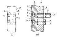
図1乃至図4は本発明による真空吸引システムおよびその制御方法を示す図である。このうち図1は真空吸引システムを示す配管図、図2は本発明の作用を示すフローチャート、図3は本発明を適用したワーク搬送装置を示す平面図、図4(a)はワーク搬送装置の拡大平面図、図4(b)はワーク搬送装置の拡大側断面図である。
【0022】
まず、図3および図4により本発明を適用したワーク搬送装置について説明する。
【0023】
図3において、ワーク搬送装置1は、ベース4に固定して設けられたテーブルベース3と、このテーブルベース3上を回転するとともに多数のワーク収納孔5を有する搬送テーブル2とを備えている。
【0024】
搬送テーブル2のワーク収納孔5は搬送テーブル2を貫通するとともに、環状に等間隔で配置され、これら多数のワーク収納孔5からなる収納孔列5aが同心円状に複数列設けられている。テーブルベース3の搬送テーブル2側の表面には、搬送テーブル2の複数の収納孔列5aにそれぞれ負圧を供給する為の真空吸引溝7が設けられ、図4に示すように搬送テーブル2の各ワーク収納孔5は真空吸引溝7と微小断面吸引溝6を介して連通されている。この場合、微小断面吸引溝6は搬送テーブル2のテーブルベース3側の表面に設けられている。また、真空吸引溝7はテーブルベース3及びベース4を貫通して設けられた複数の真空吸引孔8を介して真空配管9に連通され、この真空配管9は更に真空供給部15,17,20に連通されている。
【0025】
図3に示したワーク搬送装置1のワーク排出域においては、図4に示すようにテーブルベース3及びベース4を貫通して噴射ノズル11が設けられ、噴射ノズル11は圧縮エア配管12を介して図示しない圧縮エア制御手段に連通している。
【0026】
また図1において、前記真空供給部15,17,20は真空度制御部15と、真空発生源17と、圧縮エア発生源20とからなり、真空度制御部15はさらに真空流量調整用の絞り弁16と、圧縮エア流量調整用絞り弁19と、圧縮エア供給用電磁弁18とから構成されている。また、真空配管9には真空吸引溝7の真空度を検知する為の負圧センサ10が設けられている。
【0027】
また図1に示すように、負圧センサ10には制御部10aが接続され、この制御部10aにより圧縮エア供給用電磁弁18が駆動制御される。
【0028】
なお、図1において、ワーク収納孔5を有する搬送テーブル2と、真空吸引溝7を有するテーブルベース3とによって本発明による真空吸引システムの真空漏れ発生部が構成されている。また、真空配管9と、真空発生源17とによって真空吸引機構が構成されている。さらに負圧センサ10と、制御部10aと、圧縮エア供給用電磁弁(調整部)18と、圧縮エア発生源20とによって真空度調整機構が構成されている。
【0029】
次にこのような構成からなる本実施の形態の作用について説明する。
【0030】
図3に示すように、ワーク搬送装置1のワーク装填域において図示しない装填手段によりワーク収納孔5にワークWが装填される。ワーク収納孔5内に装填されたワークWは、搬送テーブル2により回転搬送されて、ワーク搬送装置1のワーク排出域において噴射ノズル11から噴射された圧縮エアによりワーク収納孔5から排出される。
【0031】
この間、負圧センサ10はワーク収納孔5および真空吸引溝7に連通する真空配管9内の真空度、すなわち真空漏れ発生部における真空度を検出する。
【0032】
負圧センサ10からの信号は、その後、制御部10aに送られ、制御部10aは図2に示す上限設定P2と下限設定P1の間でヒステリシスon、offを行なう。すなわち制御部10aは負圧センサ10からの真空度が上限設定P2以上になるとonとなり、その後下限設定P1以下になるとoffになるように圧縮エア供給用電磁弁18を駆動制御する。
【0033】
なお、図2において、P3は最高到達真空度を示し、本発明の機能を果す上限設定P2より高い値となっている。
【0034】
上述のように、真空発生源17から絞り弁16を経て真空吸引溝7に供給された負圧は、微小吸引溝6を介して各ワーク収納孔5に連通し、ワーク収納孔5内を負圧化する。したがって、図2に示すようにワーク装填率が上昇すると、ワーク収納孔5および真空吸引溝7内の真空度も上昇してゆく。そして負圧センサ10からの信号が上限設定P2に到達すると、制御部10aから圧縮エア吐出用電磁弁18を間欠駆動して圧縮エアを間欠噴射するようon信号が出力される。
【0035】
圧縮エア吐出用電磁弁18を間欠駆動すると、圧縮エア発生源20から供給された圧縮エアP4が絞り弁19で調整された後、噴射時間をt1、休止時間をt2として間欠的に真空配管9内に供給され、真空吸引溝7内における負圧の真空度を抑制する。
【0036】
一方、真空吸引溝7の真空度が低下して、負圧センサ10からの真空度が下限設定P1に到達すると、制御部10aは圧縮エア吐出用電磁弁18の駆動信号をoffとし、圧縮エアP4の供給を停止する。圧縮エアP4の供給が停止すると真空配管9内の真空度が再び漸増して前記動作が繰り返される。このようにして真空配管9内の真空度が上限設定P2と下限設定P1との間で略安定する。
【0037】
なお図4に示すように、ワーク収納孔5と真空吸引溝7は微小断面吸引溝6により連通され、この微小断面吸引溝6は図1に示すように、一種の絞り弁と同等の機能を果して流路抵抗を高める。このためワーク収納孔5にワークWが装填されていない場合でも、大気の吸入量を制限して真空吸引溝7内の真空度の低下を抑制することができる。
【0038】
なお、本実施の形態において、圧縮エア吐出用電磁弁18により圧縮エアを間欠噴射する例を示したが、これに限らず圧縮エアを連続的に噴射してもよい。また、本発明をワーク搬送装置1の例により説明したが、本発明はワーク搬送装置1に限定されるものではなく、圧力変動が大きい真空吸引システムであれば、このような真空吸引システムにも適用することができる。
【0039】
【発明の効果】
以上のように本発明によれば、真空漏れ発生部における真空度を安定させることができる。このため真空漏れ発生部としてワーク収納孔を有するワーク搬送テーブルを用いた場合、ワーク収納孔内にワークを安定して装填するとともに、ワーク収納孔からワークを安定して排出することができ、またワーク搬送テーブルによってワークを安定して搬送することができる。
【図面の簡単な説明】
【図1】本発明による真空吸引システムの配管図。
【図2】本発明の作用を示すフローチャート。
【図3】本発明を適用したワーク搬送装置を示す平面図。
【図4】本発明を適用したワーク搬送装置を示す拡大図。
【図5】従来の真空吸引システムを示す図。
【図6】図5に示す真空吸引システムの配管図。
【図7】ワーク装填率と真空度との関連を説明する図。
【符号の説明】
1 ワーク搬送装置
2 搬送テーブル
3 テーブルベース
4 ベース
5 ワーク収納孔
6 微小断面吸引溝
7 真空吸引溝
8 真空吸引孔
9 真空配管
10 負圧センサ
11 噴射ノズル
12 圧縮エア配管
16 絞り弁
17 真空発生源
18 圧縮エア供給用電磁弁
19 絞り弁
20 圧縮エア発生源
W ワーク[0001]
BACKGROUND OF THE INVENTION
The present invention relates to a vacuum suction system for sucking a workpiece of a chip component, which is an electronic component, into a workpiece storage hole and a control method thereof.
[0002]
[Prior art]
A conventional vacuum suction system for sucking a workpiece into the workpiece storage hole will be described with reference to FIGS.
[0003]
Of these, FIG. 5 is a partial longitudinal section showing an example in which a conventional vacuum suction system is applied to a transfer table, FIG. 6 is a piping diagram of the example shown in FIG. 5, and FIG. 7 explains the relationship between the workpiece loading rate and the degree of vacuum. It is a time chart.
[0004]
In FIG. 5, the transfer table 2 is rotatably provided on a
[0005]
The
[0006]
Further, the transfer table 2 is provided with a work discharge portion, and the work discharge portion is provided with an
[0007]
5 to 7, the
[0008]
Since leakage occurs between the
[0009]
[Problems to be solved by the invention]
By the way, even when all the
[0010]
The present invention has been made in consideration of such points, and is a vacuum that can stably load a workpiece onto a transfer table, and can stably transfer and discharge a workpiece by the transfer table. An object is to provide a suction system and a control method thereof.
[0011]
[Means for Solving the Problems]
The present invention includes a vacuum leak generation unit, a vacuum suction mechanism connected to the vacuum leak generation unit, and a vacuum degree adjustment mechanism that is connected to the vacuum suction mechanism and adjusts the degree of vacuum in the vacuum leak generation unit. A vacuum suction system characterized by the above.
[0012]
The present invention is the vacuum suction system, wherein the vacuum leak generating unit includes a transfer table having a work storage hole for storing the work.
[0013]
The present invention is the vacuum suction system, wherein the vacuum leak generation unit is further provided with a table base provided on the vacuum suction mechanism side of the transfer table and having a vacuum suction groove communicating with the work storage hole.
[0014]
The present invention is a vacuum suction system characterized in that a minute cross-section suction groove located between a work storage hole and a vacuum suction groove is provided on the surface of the transfer table on the table base side.
[0015]
According to the present invention, the vacuum degree adjusting mechanism vacuums the compressed air from the compressed air generation source based on a negative pressure sensor that detects the degree of vacuum in the vacuum leak generation unit, a compressed air generation source, and a signal from the negative pressure sensor. It is a vacuum suction system characterized by having an adjustment part sent to a leak generation part.
[0016]
According to the present invention, based on the signal from the negative pressure sensor, the adjustment unit injects compressed air when the vacuum level is equal to or higher than the upper limit value, and stops the compressed air when the vacuum level is equal to or lower than the lower limit value. It is the vacuum suction system characterized.
[0017]
The present invention relates to a vacuum leak generating unit, a vacuum suction mechanism connected to the vacuum leak generating unit, a negative pressure sensor connected to the vacuum suction mechanism and detecting a degree of vacuum in the vacuum leak generating unit, and compressed air generation A vacuum suction system control method comprising a vacuum source and a vacuum degree adjustment mechanism that adjusts a degree of vacuum in a vacuum leak generation part, and a step of generating a vacuum in the vacuum leak generation part by the vacuum degree suction mechanism And a step of detecting the degree of vacuum in the vacuum leak generation part by the negative pressure sensor of the vacuum degree adjustment mechanism, and a compressed air from the compressed air generation source by the adjustment part of the vacuum degree adjustment mechanism based on a signal from the negative pressure sensor A method for controlling the vacuum suction system, comprising the step of:
[0018]
According to the present invention, based on the signal from the negative pressure sensor, the adjustment unit injects compressed air when the vacuum level is equal to or higher than the upper limit value, and stops the compressed air when the vacuum level is equal to or lower than the lower limit value. It is the control method of the vacuum suction system characterized.
[0019]
The present invention is the control method of the vacuum suction system, wherein the adjustment unit intermittently injects the compressed air when the degree of vacuum exceeds the upper limit value based on a signal from the negative pressure sensor.
[0020]
DETAILED DESCRIPTION OF THE INVENTION
Embodiments of the present invention will be described below with reference to the drawings.
[0021]
1 to 4 are views showing a vacuum suction system and a control method thereof according to the present invention. Among these, FIG. 1 is a piping diagram showing a vacuum suction system, FIG. 2 is a flowchart showing the operation of the present invention, FIG. 3 is a plan view showing a work transfer device to which the present invention is applied, and FIG. FIG. 4B is an enlarged plan view, and FIG. 4B is an enlarged side sectional view of the work transfer device.
[0022]
First, a workpiece transfer apparatus to which the present invention is applied will be described with reference to FIGS. 3 and 4.
[0023]
In FIG. 3, the
[0024]
The
[0025]
In the work discharge area of the
[0026]
In FIG. 1, the
[0027]
Further, as shown in FIG. 1, a
[0028]
In FIG. 1, the transfer table 2 having the
[0029]
Next, the operation of the present embodiment having such a configuration will be described.
[0030]
As shown in FIG. 3, the workpiece W is loaded into the
[0031]
During this time, the
[0032]
The signal from the
[0033]
In FIG. 2, P3 indicates the maximum degree of vacuum, which is higher than the upper limit setting P2 that performs the function of the present invention.
[0034]
As described above, the negative pressure supplied from the
[0035]
When the compressed air
[0036]
On the other hand, when the degree of vacuum of the
[0037]
As shown in FIG. 4, the
[0038]
In the present embodiment, the example in which the compressed air is intermittently injected by the compressed air discharge
[0039]
【The invention's effect】
As described above, according to the present invention, it is possible to stabilize the degree of vacuum in the vacuum leak generating portion. For this reason, when a work transfer table having a work storage hole is used as a vacuum leak generating part, the work can be stably loaded into the work storage hole and the work can be stably discharged from the work storage hole. The workpiece can be stably conveyed by the workpiece conveyance table.
[Brief description of the drawings]
FIG. 1 is a piping diagram of a vacuum suction system according to the present invention.
FIG. 2 is a flowchart showing the operation of the present invention.
FIG. 3 is a plan view showing a workpiece transfer apparatus to which the present invention is applied.
FIG. 4 is an enlarged view showing a work transfer device to which the present invention is applied.
FIG. 5 is a diagram showing a conventional vacuum suction system.
6 is a piping diagram of the vacuum suction system shown in FIG.
FIG. 7 is a diagram for explaining a relationship between a workpiece loading rate and a degree of vacuum.
[Explanation of symbols]
DESCRIPTION OF
Claims (4)
Translated fromJapaneseこの真空漏れ発生部に接続された真空吸引機構と、
この真空吸引機構に接続され、真空漏れ発生部における真空度を検出する負圧センサと、負圧センサからの信号に基づいて真空漏れ発生部における真空度を調整する調整部とを有する真空度調整機構と、
を備え、
真空漏れ発生部は、真空吸引機構側に設けられ、真空吸引溝を有するテーブルベースと、テーブルベース上に回転自在に設けられ、ワークを収納するとともに真空吸引溝に連通する複数のワーク収納孔を有する搬送テーブルとを有し、負圧センサは搬送テーブルの複数のワーク収納孔の真空度を検出し、調整部は複数のワーク収納孔の真空度を調整し、真空度調整機構は、圧縮エア発生源を有し、調整部は負圧センサからの信号に基づいて圧縮エア発生源からの圧縮エアを真空漏れ発生部の複数のワーク収納孔に送り、調整部は負圧センサからの信号に基づいて、真空度がワーク装填率が上昇して定まる上限値以上となったとき圧縮エアを噴射し、真空度がワークの装填率が低下して定まる下限値以下となったとき圧縮エアの噴射を停止することを特徴とする真空吸引システム。A vacuum leak generator,
A vacuum suction mechanism connected to the vacuum leak generation unit;
Vacuum degree adjustment connected to the vacuum suction mechanism and having a negative pressure sensor for detecting the degree of vacuum in the vacuum leak generating part and an adjusting part for adjusting the degree of vacuum in the vacuum leak generating part based on a signal from the negative pressure sensor Mechanism,
With
The vacuum leak generating unit is provided on the vacuum suction mechanism side, and has a table base having a vacuum suction groove, and aplurality of work storage holes that are rotatably provided on the table base and store workpieces and communicate with the vacuum suction grooves. The negative pressure sensor detects the degree of vacuum of theplurality of work storage holes of the transfer table, the adjustment unit adjusts the degree of vacuum of theplurality of work storage holes,and the vacuum degree adjustment mechanism includes compressed air. The adjusting unit sends the compressed air from the compressed air generating source to a plurality of work storage holes of the vacuum leak generating unit based on the signal from the negative pressure sensor, and the adjusting unit converts the signal from the negative pressure sensor to Based on the above, compressed air is injected when the degree of vacuum is equal to or higher than the upper limit value determined by the workpiece loading rate rising, and compressed air is injected when the vacuum level is lower than the lower limit value determined by lowering the workpiece loading rate. to stop the Vacuum system comprising and.
この真空漏れ発生部に接続された真空吸引機構と、
この真空吸引機構に接続され、真空漏れ発生部における真空度を検出する負圧センサと、圧縮エア発生源と、調整部とを有し真空漏れ発生部における真空度を調整する真空度調整機構とを備え、真空漏れ発生部は、真空吸引機構側に設けられ、真空吸引溝を有するテーブルベースと、テーブルベース上に回転自在に設けられ、ワークを収納するとともに真空吸引溝に連通する複数のワーク収納孔を有する搬送テーブルとを有し、負圧センサは搬送テーブルの複数のワーク収納孔の真空度を検出し、調整部は複数のワーク収納孔の真空度を調整する真空吸引システムの制御方法において、
真空度吸引機構により真空漏れ発生部の複数のワーク収納孔に真空を生じさせる工程と、
真空度調整機構の負圧センサにより真空漏れ発生部の複数のワーク収納孔における真空度を検出する工程と、
負圧センサからの信号に基づいて、真空度調整機構の調整部により圧縮エア発生源からの圧縮エアを真空漏れ発生部の複数のワーク収納孔へ送る工程と、
を備え、
調整部は負圧センサからの信号に基づいて、真空度がワーク装填率が上昇して定まる上限値以上となったとき圧縮エアを噴射し、真空度がワークの装填率が低下して定まる下限値以下となったとき圧縮エアの噴射を停止することを特徴とする真空吸引システムの制御方法。A vacuum leak generator,
A vacuum suction mechanism connected to the vacuum leak generation unit;
A vacuum degree adjusting mechanism that is connected to the vacuum suction mechanism and includes a negative pressure sensor that detects the degree of vacuum in the vacuum leak generation unit, a compressed air generation source, and an adjustment unit, and adjusts the vacuum degree in the vacuum leak generation unit. The vacuum leak generating portion is provided on the vacuum suction mechanism side, and has a table base having a vacuum suction groove, and aplurality of workpieces that are rotatably provided on the table base and house the workpiece and communicate with the vacuum suction groove. And a negative pressure sensor for detecting a degree of vacuum of aplurality of work storage holes of the transfer table, and an adjustment unit adjusting a vacuum degree of theplurality of work storage holes. In
A step of generating a vacuum in aplurality of work storage holes of a vacuum leak generation portion by a vacuum suction mechanism;
A step of detecting the degree of vacuum in theplurality of work storage holes of the vacuum leak generation part by a negative pressure sensor of the degree of vacuum adjustment mechanism;
A step of sending compressed air from a compressed air generation source to aplurality of workpiece housing holes of a vacuum leak generation unit by an adjustment unit of a vacuum degree adjustment mechanism based on a signal from a negative pressure sensor;
With
Based on the signal from the negative pressure sensor, the adjustment unit injects compressed air when the degree of vacuum reaches or exceeds the upper limit determined by the workpiece loading rate increasing, and the vacuum level is determined by the lower workpiece loading rate. A method for controllinga vacuum suction system,characterized in that the injection of compressed air is stopped when the value becomes less than or equal to the value .
Priority Applications (5)
| Application Number | Priority Date | Filing Date | Title |
|---|---|---|---|
| JP2003011070AJP4346912B2 (en) | 2003-01-20 | 2003-01-20 | Vacuum suction system and control method thereof |
| TW93100702ATWI279173B (en) | 2003-01-20 | 2004-01-12 | Vacuum suction system and method of controlling the same |
| KR1020040003314AKR100769388B1 (en) | 2003-01-20 | 2004-01-16 | Vacuum suction system and method for controlling the same |
| US10/758,012US7931042B2 (en) | 2003-01-20 | 2004-01-16 | Vacuum suction system and method of controlling the same |
| CNB2004100029167ACN100564205C (en) | 2003-01-20 | 2004-01-20 | Vacuum attraction system and control method thereof |
Applications Claiming Priority (1)
| Application Number | Priority Date | Filing Date | Title |
|---|---|---|---|
| JP2003011070AJP4346912B2 (en) | 2003-01-20 | 2003-01-20 | Vacuum suction system and control method thereof |
Publications (2)
| Publication Number | Publication Date |
|---|---|
| JP2004224454A JP2004224454A (en) | 2004-08-12 |
| JP4346912B2true JP4346912B2 (en) | 2009-10-21 |
Family
ID=32732768
Family Applications (1)
| Application Number | Title | Priority Date | Filing Date |
|---|---|---|---|
| JP2003011070AExpired - LifetimeJP4346912B2 (en) | 2003-01-20 | 2003-01-20 | Vacuum suction system and control method thereof |
Country Status (5)
| Country | Link |
|---|---|
| US (1) | US7931042B2 (en) |
| JP (1) | JP4346912B2 (en) |
| KR (1) | KR100769388B1 (en) |
| CN (1) | CN100564205C (en) |
| TW (1) | TWI279173B (en) |
Families Citing this family (18)
| Publication number | Priority date | Publication date | Assignee | Title |
|---|---|---|---|---|
| JP4500938B2 (en)* | 2004-07-21 | 2010-07-14 | 株式会社 東京ウエルズ | Vacuum suction system |
| JP4124242B2 (en)* | 2006-05-24 | 2008-07-23 | 株式会社村田製作所 | Work transfer device and electronic component transfer device |
| JP4079179B2 (en)* | 2006-06-02 | 2008-04-23 | 株式会社村田製作所 | Work transfer device and electronic component transfer device |
| US20100269700A1 (en)* | 2009-04-22 | 2010-10-28 | Han Zhen-Zhong | Vacuum adsorption apparatus |
| US20100283194A1 (en)* | 2009-05-11 | 2010-11-11 | Han Zhen-Zhong | Energy-saving vacuum adsorption apparatus |
| JP5294213B2 (en)* | 2009-11-27 | 2013-09-18 | 株式会社 東京ウエルズ | Work classification discharge system and work classification discharge method |
| KR101559420B1 (en)* | 2011-01-19 | 2015-10-13 | (주)테크윙 | Semiconductor device holding and holding release pressure providing system for test handler |
| DE102011118173B4 (en)* | 2011-11-10 | 2015-10-08 | Festo Ag & Co. Kg | Method for operating a vacuum gripper, vacuum controller and manipulator |
| CN103027417B (en)* | 2012-07-30 | 2014-07-23 | 际华三五零二职业装有限公司 | Finished product taking and stacking-up device of hot-pressing machine of pocket cloth edgefolds of uniform clothes |
| CN102785796B (en)* | 2012-08-20 | 2014-07-23 | 楚天科技股份有限公司 | Vacuum separation system and bottle discharging device |
| CN103057957B (en)* | 2013-01-14 | 2015-05-27 | 浙江大学 | Squid foot sorting device |
| CN103406278B (en)* | 2013-07-26 | 2015-09-09 | 潍坊永昱电控科技有限公司 | A kind of gas circuit of LED wafer automatic fraction collector welding tip |
| JP6435535B2 (en)* | 2015-01-07 | 2018-12-12 | 株式会社 東京ウエルズ | Work characteristic measuring apparatus and work characteristic measuring method |
| SG11201707202QA (en)* | 2015-05-29 | 2017-10-30 | Rasco Gmbh | A component handling assembly |
| TWI749288B (en)* | 2018-01-24 | 2021-12-11 | 日商東京威爾斯股份有限公司 | Vacuum suction arm, collet holder and nozzle collet |
| CN109249309B (en)* | 2018-11-10 | 2024-03-08 | 宇晶机器(长沙)有限公司 | Vacuum pipeline self-cleaning control system of continuous multi-station polishing machine |
| KR102485933B1 (en)* | 2021-01-27 | 2023-01-11 | (주) 테크윈 | Powder feeding system and powder feeding method |
| JP2024122409A (en)* | 2023-02-28 | 2024-09-09 | 株式会社村田製作所 | Conveyor |
Family Cites Families (15)
| Publication number | Priority date | Publication date | Assignee | Title |
|---|---|---|---|---|
| US4557659A (en)* | 1982-09-14 | 1985-12-10 | M. Scaglia S.P.A. | Device for supporting and handling loads by means of vacuum operated suction pads |
| JP2581205B2 (en)* | 1989-03-01 | 1997-02-12 | 富士通株式会社 | Replacement device |
| JPH03162310A (en) | 1989-11-21 | 1991-07-12 | Seiwa Sangyo Kk | Device for aligning polarity of chip-like electronic parts |
| EP0463853B1 (en)* | 1990-06-29 | 1998-11-04 | Canon Kabushiki Kaisha | Vacuum chuck |
| JP2681722B2 (en) | 1990-11-29 | 1997-11-26 | ハウス食品株式会社 | Directional filling device |
| US5201560A (en)* | 1991-01-24 | 1993-04-13 | John A. Blatt | Vacuum cup control apparatus |
| US5842579A (en)* | 1995-11-16 | 1998-12-01 | Electro Scientific Industries, Inc. | Electrical circuit component handler |
| KR100254781B1 (en) | 1996-08-30 | 2000-05-01 | Lg Ind Systems Co Ltd | Apparatus for compensating vacuum of surface mounting devices mounter and method thereof |
| JPH10340832A (en)* | 1997-04-08 | 1998-12-22 | Murata Mfg Co Ltd | Characteristics measurement/packaging device for capacitor |
| JP3395628B2 (en)* | 1998-01-27 | 2003-04-14 | 株式会社村田製作所 | Chip component separation and supply device |
| US5961169A (en)* | 1998-07-27 | 1999-10-05 | Strasbaugh | Apparatus for sensing the presence of a wafer |
| JP3671789B2 (en)* | 2000-01-13 | 2005-07-13 | 株式会社村田製作所 | Parts handling equipment and handling method |
| JP2002046858A (en) | 2000-08-01 | 2002-02-12 | Tokyo Weld Co Ltd | Work carrier device |
| CN2435371Y (en)* | 2000-08-22 | 2001-06-20 | 华中科技大学 | Vacuum picking-up and depositing device for operation of submillimeter grade microminiature object |
| JP3690257B2 (en)* | 2000-08-28 | 2005-08-31 | 株式会社村田製作所 | Chip parts transfer device |
- 2003
- 2003-01-20JPJP2003011070Apatent/JP4346912B2/ennot_activeExpired - Lifetime
- 2004
- 2004-01-12TWTW93100702Apatent/TWI279173B/ennot_activeIP Right Cessation
- 2004-01-16USUS10/758,012patent/US7931042B2/enactiveActive
- 2004-01-16KRKR1020040003314Apatent/KR100769388B1/ennot_activeExpired - Lifetime
- 2004-01-20CNCNB2004100029167Apatent/CN100564205C/ennot_activeExpired - Lifetime
Also Published As
| Publication number | Publication date |
|---|---|
| CN1533969A (en) | 2004-10-06 |
| KR20040067935A (en) | 2004-07-30 |
| CN100564205C (en) | 2009-12-02 |
| TW200417297A (en) | 2004-09-01 |
| TWI279173B (en) | 2007-04-11 |
| US20040145103A1 (en) | 2004-07-29 |
| US7931042B2 (en) | 2011-04-26 |
| KR100769388B1 (en) | 2007-10-22 |
| JP2004224454A (en) | 2004-08-12 |
Similar Documents
| Publication | Publication Date | Title |
|---|---|---|
| JP4346912B2 (en) | Vacuum suction system and control method thereof | |
| US20250140594A1 (en) | Substrate holding apparatus, substrate suction determination method, substrate polishing apparatus, substrate polishing method, method of removing liquid from upper surface of wafer to be polished, elastic film for pressing wafer against polishing pad, substrate release method, and constant amount gas supply apparatus | |
| US7556246B2 (en) | Unloading method of object, program storage medium, and mounting mechanism | |
| KR100380666B1 (en) | Application device | |
| JP2011014582A (en) | Electronic component carrier | |
| TWI736602B (en) | Substrate processing apparatus | |
| JP4500938B2 (en) | Vacuum suction system | |
| US20220033208A1 (en) | Transport device | |
| KR101571646B1 (en) | Apparatus for supplying laver using a non-contact pad | |
| JP4136692B2 (en) | Pellet conveying device, pellet bonding method and pellet bonding device | |
| JP2009050959A (en) | Plate-shaped material transfer device | |
| JP4372634B2 (en) | Work transfer device | |
| US9915261B2 (en) | Substrate treating apparatus, drive assembly, and drive member controlling method | |
| JPH09183089A (en) | Search type vacuum suction device and air control valve for vacuum suction | |
| JP3870363B2 (en) | Solder ball mounting device | |
| JPH09129710A (en) | Automatic wafer transfer/loading apparatus | |
| JP6847286B2 (en) | Board processing equipment | |
| JP2004186317A (en) | Surface mounting apparatus | |
| WO2023073776A1 (en) | Component mounting device | |
| CN107534010A (en) | Part Handling Components | |
| TW202510184A (en) | Separation device, separation system, and separation method | |
| CN119230470A (en) | Needle lifting device, semiconductor process equipment and pressure control method | |
| JPH06282961A (en) | Method and device for supplying flexible disks | |
| JP2002347919A (en) | Parts supply device | |
| JP2016152303A (en) | Delivery device and method of wafer |
Legal Events
| Date | Code | Title | Description |
|---|---|---|---|
| A621 | Written request for application examination | Free format text:JAPANESE INTERMEDIATE CODE: A621 Effective date:20051125 | |
| A977 | Report on retrieval | Free format text:JAPANESE INTERMEDIATE CODE: A971007 Effective date:20081114 | |
| A131 | Notification of reasons for refusal | Free format text:JAPANESE INTERMEDIATE CODE: A131 Effective date:20081118 | |
| A521 | Request for written amendment filed | Free format text:JAPANESE INTERMEDIATE CODE: A523 Effective date:20081226 | |
| A02 | Decision of refusal | Free format text:JAPANESE INTERMEDIATE CODE: A02 Effective date:20090306 | |
| A521 | Request for written amendment filed | Free format text:JAPANESE INTERMEDIATE CODE: A523 Effective date:20090417 | |
| A911 | Transfer to examiner for re-examination before appeal (zenchi) | Free format text:JAPANESE INTERMEDIATE CODE: A911 Effective date:20090512 | |
| TRDD | Decision of grant or rejection written | ||
| A01 | Written decision to grant a patent or to grant a registration (utility model) | Free format text:JAPANESE INTERMEDIATE CODE: A01 Effective date:20090616 | |
| A01 | Written decision to grant a patent or to grant a registration (utility model) | Free format text:JAPANESE INTERMEDIATE CODE: A01 | |
| A61 | First payment of annual fees (during grant procedure) | Free format text:JAPANESE INTERMEDIATE CODE: A61 Effective date:20090715 | |
| R150 | Certificate of patent or registration of utility model | Ref document number:4346912 Country of ref document:JP Free format text:JAPANESE INTERMEDIATE CODE: R150 Free format text:JAPANESE INTERMEDIATE CODE: R150 | |
| FPAY | Renewal fee payment (event date is renewal date of database) | Free format text:PAYMENT UNTIL: 20120724 Year of fee payment:3 | |
| FPAY | Renewal fee payment (event date is renewal date of database) | Free format text:PAYMENT UNTIL: 20130724 Year of fee payment:4 | |
| R250 | Receipt of annual fees | Free format text:JAPANESE INTERMEDIATE CODE: R250 | |
| R250 | Receipt of annual fees | Free format text:JAPANESE INTERMEDIATE CODE: R250 | |
| R250 | Receipt of annual fees | Free format text:JAPANESE INTERMEDIATE CODE: R250 | |
| R250 | Receipt of annual fees | Free format text:JAPANESE INTERMEDIATE CODE: R250 | |
| R250 | Receipt of annual fees | Free format text:JAPANESE INTERMEDIATE CODE: R250 | |
| R250 | Receipt of annual fees | Free format text:JAPANESE INTERMEDIATE CODE: R250 | |
| R250 | Receipt of annual fees | Free format text:JAPANESE INTERMEDIATE CODE: R250 | |
| R250 | Receipt of annual fees | Free format text:JAPANESE INTERMEDIATE CODE: R250 | |
| R250 | Receipt of annual fees | Free format text:JAPANESE INTERMEDIATE CODE: R250 | |
| R250 | Receipt of annual fees | Free format text:JAPANESE INTERMEDIATE CODE: R250 | |
| R250 | Receipt of annual fees | Free format text:JAPANESE INTERMEDIATE CODE: R250 | |
| EXPY | Cancellation because of completion of term |