JP4346836B2 - Information playback device - Google Patents
Information playback deviceDownload PDFInfo
- Publication number
- JP4346836B2 JP4346836B2JP2001150928AJP2001150928AJP4346836B2JP 4346836 B2JP4346836 B2JP 4346836B2JP 2001150928 AJP2001150928 AJP 2001150928AJP 2001150928 AJP2001150928 AJP 2001150928AJP 4346836 B2JP4346836 B2JP 4346836B2
- Authority
- JP
- Japan
- Prior art keywords
- data
- rotating body
- display
- reproduction
- audio information
- Prior art date
- Legal status (The legal status is an assumption and is not a legal conclusion. Google has not performed a legal analysis and makes no representation as to the accuracy of the status listed.)
- Expired - Lifetime
Links
- 238000000034methodMethods0.000claimsdescription57
- 230000000694effectsEffects0.000claimsdescription55
- 230000008569processEffects0.000claimsdescription51
- 230000003287optical effectEffects0.000claimsdescription49
- 238000003860storageMethods0.000claimsdescription25
- 238000001514detection methodMethods0.000claimsdescription21
- 101100028477Drosophila melanogaster Pak geneProteins0.000description87
- 238000012545processingMethods0.000description46
- 102100038919Dynein axonemal assembly factor 1Human genes0.000description22
- 101000955707Homo sapiens Dynein axonemal assembly factor 1Proteins0.000description22
- 238000003825pressingMethods0.000description20
- 101150052726DSP2 geneProteins0.000description16
- 101150115013DSP1 geneProteins0.000description14
- 230000005236sound signalEffects0.000description14
- 101100063532Arabidopsis thaliana DMP9 geneProteins0.000description12
- 238000010586diagramMethods0.000description11
- 101150062184DSP4 geneProteins0.000description8
- SDJLVPMBBFRBLL-UHFFFAOYSA-Ndsp-4Chemical compoundClCCN(CC)CC1=CC=CC=C1BrSDJLVPMBBFRBLL-UHFFFAOYSA-N0.000description8
- 238000003780insertionMethods0.000description6
- 230000037431insertionEffects0.000description6
- 238000000926separation methodMethods0.000description6
- 230000006870functionEffects0.000description5
- 230000007246mechanismEffects0.000description5
- 230000002093peripheral effectEffects0.000description5
- 101100388212Arabidopsis thaliana DSP3 geneProteins0.000description4
- 230000008859changeEffects0.000description4
- 230000003247decreasing effectEffects0.000description4
- 239000000284extractSubstances0.000description3
- 239000004973liquid crystal related substanceSubstances0.000description3
- 238000013459approachMethods0.000description2
- 230000002457bidirectional effectEffects0.000description2
- 238000004519manufacturing processMethods0.000description2
- 238000003672processing methodMethods0.000description2
- 238000005070samplingMethods0.000description2
- 239000004065semiconductorSubstances0.000description2
- 238000007493shaping processMethods0.000description2
- 238000005452bendingMethods0.000description1
- 230000004397blinkingEffects0.000description1
- 238000004364calculation methodMethods0.000description1
- 238000013500data storageMethods0.000description1
- 230000007423decreaseEffects0.000description1
- 230000003111delayed effectEffects0.000description1
- 239000003989dielectric materialSubstances0.000description1
- 238000005516engineering processMethods0.000description1
- 230000009191jumpingEffects0.000description1
- 238000010137moulding (plastic)Methods0.000description1
- 230000004044responseEffects0.000description1
- 239000000758substrateSubstances0.000description1
- 238000012546transferMethods0.000description1
Images


Classifications
- G—PHYSICS
- G11—INFORMATION STORAGE
- G11B—INFORMATION STORAGE BASED ON RELATIVE MOVEMENT BETWEEN RECORD CARRIER AND TRANSDUCER
- G11B27/00—Editing; Indexing; Addressing; Timing or synchronising; Monitoring; Measuring tape travel
- G11B27/005—Reproducing at a different information rate from the information rate of recording
- G—PHYSICS
- G10—MUSICAL INSTRUMENTS; ACOUSTICS
- G10H—ELECTROPHONIC MUSICAL INSTRUMENTS; INSTRUMENTS IN WHICH THE TONES ARE GENERATED BY ELECTROMECHANICAL MEANS OR ELECTRONIC GENERATORS, OR IN WHICH THE TONES ARE SYNTHESISED FROM A DATA STORE
- G10H1/00—Details of electrophonic musical instruments
- G10H1/0091—Means for obtaining special acoustic effects
- G—PHYSICS
- G11—INFORMATION STORAGE
- G11B—INFORMATION STORAGE BASED ON RELATIVE MOVEMENT BETWEEN RECORD CARRIER AND TRANSDUCER
- G11B19/00—Driving, starting, stopping record carriers not specifically of filamentary or web form, or of supports therefor; Control thereof; Control of operating function ; Driving both disc and head
- G—PHYSICS
- G10—MUSICAL INSTRUMENTS; ACOUSTICS
- G10H—ELECTROPHONIC MUSICAL INSTRUMENTS; INSTRUMENTS IN WHICH THE TONES ARE GENERATED BY ELECTROMECHANICAL MEANS OR ELECTRONIC GENERATORS, OR IN WHICH THE TONES ARE SYNTHESISED FROM A DATA STORE
- G10H2210/00—Aspects or methods of musical processing having intrinsic musical character, i.e. involving musical theory or musical parameters or relying on musical knowledge, as applied in electrophonic musical tools or instruments
- G10H2210/155—Musical effects
- G10H2210/195—Modulation effects, i.e. smooth non-discontinuous variations over a time interval, e.g. within a note, melody or musical transition, of any sound parameter, e.g. amplitude, pitch, spectral response or playback speed
- G10H2210/241—Scratch effects, i.e. emulating playback velocity or pitch manipulation effects normally obtained by a disc-jockey manually rotating a LP record forward and backward
- G—PHYSICS
- G11—INFORMATION STORAGE
- G11B—INFORMATION STORAGE BASED ON RELATIVE MOVEMENT BETWEEN RECORD CARRIER AND TRANSDUCER
- G11B2220/00—Record carriers by type
- G11B2220/20—Disc-shaped record carriers
- G11B2220/25—Disc-shaped record carriers characterised in that the disc is based on a specific recording technology
- G11B2220/2537—Optical discs
- G11B2220/2545—CDs
- G—PHYSICS
- G11—INFORMATION STORAGE
- G11B—INFORMATION STORAGE BASED ON RELATIVE MOVEMENT BETWEEN RECORD CARRIER AND TRANSDUCER
- G11B2220/00—Record carriers by type
- G11B2220/20—Disc-shaped record carriers
- G11B2220/25—Disc-shaped record carriers characterised in that the disc is based on a specific recording technology
- G11B2220/2537—Optical discs
- G11B2220/2562—DVDs [digital versatile discs]; Digital video discs; MMCDs; HDCDs
Landscapes
- Physics & Mathematics (AREA)
- Engineering & Computer Science (AREA)
- Acoustics & Sound (AREA)
- Multimedia (AREA)
- Signal Processing For Digital Recording And Reproducing (AREA)
- Electrophonic Musical Instruments (AREA)
- Management Or Editing Of Information On Record Carriers (AREA)
Description
Translated fromJapanese【0001】
【発明の属する技術分野】
本発明は、音楽や音声等のオーディオ情報にイフェクト効果を施して再生する情報再生装置に関する。
【0002】
【従来の技術】
従来、LP等のアナログレコードをアナログレコードプレーヤで再生し、その再生中に、手操作によってアナログレコードの回転方向と回転速度を強制的に変化させることにより、再生音に様々なイフェクト効果を付与する演出技法が知られている。
【0003】
例えば、ディスコテック等で見られる光景として、ディスクジョッキーと呼ばれる演出者が、アナログレコードプレーヤで再生中のアナログレコードに手を触れ、本来の回転数とは異なった速度で強制的に正回転させたり逆回転させることによって、所謂スクラッチ音と呼ばれる擬音(「キュキュ」、「ガシャガシャ」等の擬音)を生じさせる等、様々な効果音を得るようにしている。
【0004】
【発明が解決しようとする課題】
ところが、デジタル技術の進展に伴って、情報がデジタル記録されたCD(Compact Disc)やDVD(Digital Versatil Disc)等のストレージ媒体が普及し、こうしたストレージ媒体を用いて従来のアナログレコードと同様の手操作によってイフェクト効果を得ることは困難となっている。
【0005】
つまり、アナログレコードの場合には、音楽等のオーディオ信号が記録トラックに沿ってそのまま連続記録されているため、レコード針によるアナログレコードの再生位置(走査位置)と、再生される音とを一対一に対応付けて認識することができ、そのため、手操作によって所望のイフェクト効果を得ることが可能である。
【0006】
しかし、情報がデジタル記録されたCDやDVD等のストレージ媒体の場合には、人間の感覚では直感的に知ることができない特殊なデジタル技術によって情報記録及び情報再生が行われるため、例えばCDプレーヤで再生中のCDを、アナログレコードの場合のように手操作によって扱っても、所望のイフェクト効果を得ることができないという問題があった。
【0007】
特に、CDプレーヤやDVDプレーヤは、光学読取り装置であるピックアップに対してCDやDVDを所定方向に回転させながら情報を読み取って再生音を生成するように規格で定められており、ピックアップに対してCDやDVDを逆方向に回転させながら情報を逆順で読み取って再生音を生成するようには規格化されていない。そのため、手操作によってCDやDVDを上記所定方向とは逆の方向に単に回転させても、適切な情報読取りと再生がなされなくなってしまことから、上記のスクラッチ音等の擬音を発生させることはできなかった。
【0008】
本発明はこうした従来の課題に鑑みてなされたものであり、例えばCDやDVD等のデジタル記録がなされているストレージ媒体を用いて、アナログレコードを操作するのと同様の感覚でイフェクト効果を得ることを可能にする情報再生装置を提供することを目的とする。
【0009】
【課題を解決するための手段】
上記目的を達成するために請求項1に記載の発明は、オーディオ情報を再生する情報再生装置において、前記オーディオ情報を記憶する記憶手段と、回転自在に設けられた円盤形状の回転体と、前記回転体の停止を検出すると共に、手回し操作された際の前記回転体の回転方向及び角速度を検出する検出手段と、前記回転体が所定の力以上で押圧されたか否かを検知する検知手段と、前記記憶手段に記憶されているオーディオ情報を再生する再生手段と、前記再生手段を制御する制御手段と、を有し、前記制御手段は、前記回転体が所定の力以上で押圧されたことを前記検知手段が検知し且つ回転体の回転方向及び角速度を前記検出手段が検出すると、前記記憶手段に記憶されているオーディオ情報を読み出して、当該検出された回転方向及び角速度に応じた効果音を、前記オーディオ情報に付与する編集処理を行い、当該編集処理を行ったオーディオ情報を前記再生手段にて再生させ、また、前記回転体が所定の力以上で押圧されたことを前記検知手段が検知せず且つ回転体の回転方向及び角速度を前記検出手段が検出した場合、前記再生手段にて再生されている当該時点のオーディオ情報の位置を基準位置として、当該検出された回転方向及び角速度に応じて、当該オーディオ情報の再生すべき位置をジャンプさせ、当該ジャンプ後の位置から、前記再生手段にて当該オーディオ情報を再生させること、を特徴とする。
【0019】
【発明の実施の形態】
以下、本発明の情報再生装置の実施の形態を図面を参照して説明する。尚、本実施形態の情報再生装置は、再生情報に様々なイフェクト(編集)効果を付与することが可能であることから、以下、オーディオ編集装置と呼ぶこととする。
【0020】
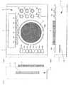
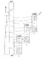
図1は、オーディオ編集装置1の外観構成を示す図であり、同図(a)は正面図、同図(b)は手前から見た側面図、同図(c)は横から見た側面図である。
【0021】
図1(a)において、オーディオ編集装置1の筐体の操作面2には、液晶ディスプレイで形成された表示部3と、回動自在な円盤形状のジョグダイヤル4と、プッシュプル型の押釦スイッチから成る複数個の操作キー5a〜5f,6a〜6hと、回動自在なロータリスイッチや回動型の可変抵抗器から成る複数個の操作キー7a〜7fと、スライド式可変抵抗器から成る複数個の操作キー8a,8bが設けられ、これらの操作キー5a〜5f,6a〜6h,7a〜7f,8a,8bによって、後述の操作部30が構成されている。
【0022】
オーディオ編集装置1の筐体の手前から見た側面9には、図1(b)に示すように、半導体メモリを内蔵したメモリカードを着脱自在に挿入するためのスリット形状の開口部を有するメモリカードスロット10が設けられ、更に、図1(c)に示すように、オーディオ編集装置1の筐体の横から見た側面12には、CD又はDVD(以下、「光ディスク」という)を着脱自在に挿入するためのスリット形状のディスク挿入口14が設けられている。
【0023】
光ディスクがディスク挿入口14に挿入されると、ディスク挿入口14の奥に設けられているオートローディング機構(図示省略)が自動的に起動して、ジョグダイヤル4の略下側に設けられているクランプ位置へ光ディスクを搬入し、後述するスピンドルモータ16の駆動軸に設けられているハブ部(図示省略)に装填する。そして、再生開始と再生停止の指示をするために設けられている操作キー5aが押下操作されると、スピンドルモータ16が所定方向に回転すると共に、後述のディスク再生部(図5参照)15が光ディスクに記録されている情報(以下、「データ」という)を再生する。
【0024】
また、押下されていた操作キー5aが再び押されると、スピンドルモータ16の回転が停止すると共に、ディスク再生部15による光ディスクの再生動作が停止する。また、イジェクト釦と呼ばれる操作キー5bが押下操作されると、上記のオートローディング機構がアンローディングの状態となって、クランプ位置に在った光ディスクをディスク挿入口14の外へ搬出する。
【0025】
ジョグダイヤル4は、ディスク再生部15が光ディスクに記録されているデータを読み取って再生音を再生する際の再生速度と再生方向を可変設定するために設けられている。
【0026】
ここで、ジョグダイヤル4の構成については後述することとし、まず、ジョグダイヤル4の機能について説明する。
【0027】
ユーザーが手回し操作によってジョグダイヤル4の回転方向と回転速度を適宜に変化させると、その回転方向に応じてフォワード再生とリバース再生を設定することができ、更に、ジョグダイヤル4の回転速度に応じて、スピーカやヘッドフォンで再生される再生音の音調を変化させることができるようになっている。
【0028】
上記のフォワード再生とは、LP等のアナログレコードを正転方向に回転させて音楽等を再生させた場合と同様に、光ディスクのデータを、記録されているストリームの順に再生することを言う。したがって、ジョグダイヤル4が時計回り方向に回転操作されるのに応じて、ディスク再生部15はフォワード再生を行い、音楽等を通常の音として再生するようになっている。また、ジョグダイヤル4が操作されることなく停止しているときにも、フォワード再生が行われるようになっている。
【0029】
上記のリバース再生とは、アナログレコードを逆転方向に回転させて音楽等を再生させた場合と同様に、光ディスクのデータを、記録されているストリームの順とは逆の順番で再生することを言う。つまり、アナログレコードでは音楽等が連続記録(アナログ記録)されているため、アナログレコードを逆転方向に回転させると、音楽等を逆の方向から再生することになって、本来の音楽等とは違った擬音が再生されることになるが、ディスク再生部15も、ジョグダイヤル4が反時計回り方向に回転操作されると、光ディスクにデジタル記録されている個々のデータを逆のストリームの順番で再生することにより、あたかもアナログレコードを逆転方向に回転させて再生させた場合と同様の擬音を生じさせるようになっている。
【0030】
但し、ディスク再生部15は、光ディスク自体を逆回転させることはせず、後述のバッチ処理によって、アナログレコードを逆転方向に回転させるのと同等な効果を発揮するようになっている。
【0031】
このようにアナログレコードを逆転再生するのと同様の機能が備えられているため、例えば所謂ディスクジョッキーと呼ばれる演奏者等のユーザーが、ジョグダイヤル4を手回し操作によって時計回り方向と反時計回り方向へ往復回転を繰り返すと、所謂スクラッチ音と呼ばれる擬音(「キュキュ」、「ガシャガシャ」等の擬音)を生じさせることができる。また、上記のスクラッチ音等を生じさせるべくジョグダイヤル4を操作すると、光ディスクを用いてラップ音楽等を生成するための編集を行うことが可能となっている。
【0032】
操作キー5c,5d,5eは、キュー(Cue)釦と呼ばれ、光ディスクの再生中にユーザーが操作キー5cを押下操作すると、その再生時点の経過トラック時間を履歴情報として後述のシステムコントローラ29が記憶する。また、操作キー5cが押下操作される度毎に、夫々の再生時点の経過トラック時間を履歴情報として記憶することにより、複数の再生時点の経過トラック時間を記憶することが可能となっている。
【0033】
ユーザーが操作キー5dを押下操作すると、システムコントローラ29に記憶されている履歴情報が表示部3に表示され、更にユーザーが操作キー5eを押下操作すると、表示部3に表示された履歴情報(すなわち、経過トラック時間)を頭出し位置として、再生を開始するようになっている。また、操作キー5dが押下操作される度に、システムコントローラ29に記憶されている履歴情報が順繰りに表示部3に表示される。このため、ユーザーは操作キー5c,5d,5eを適宜に操作することで、所望の経過トラック時間を頭出し位置に設定して再生を開始させることが可能となっている。
【0034】
尚、光ディスクにコントロールデータとして記録されているサブコードデータをディスク再生部15が再生し、サブコードデータ中に含まれているQチャンネルコードデータから上記の経過トラック時間を求めるようになっている。
【0035】
操作キー5fは、ディスク再生部15に対してイフェクト処理の開始を指示するために設けられている。ディスク再生部15は、ユーザーにより操作キー5fが押下操作されるとイフェクト処理を開始し、再び操作キー5fが押下操作されると、イフェクト処理を終了する。
【0036】
残余の操作キー6f〜6hについての詳細な説明は割愛するが、本オーディオ編集装置1に設けられている様々な機能をユーザーが適宜に選択指定するために設けられている。
【0037】
操作キー7a〜7fは、ディスク再生部15に対して、再生データに様々なイフェクト処理を施すための指示をするために設けられている。ユーザーは操作キー7a〜7fの夫々の回動角を変えることで、イフェクト処理の方法を指定できるようになっている。
【0038】
ここで、代表例として操作キー7a,7bの機能を説明する。操作キー7a,7bは共に、3段切替型のロータリースイッチで形成されており、イフェクト処理の方法を指定するために設けられた「第1の指定位置」及び「第2の指定位置」と、イフェクト処理を解除するために第1,第2の指定位置の間に設けられた「OFF位置」との3つの位置をユーザーが適宜に切り替えられるようになっている。
【0039】
ディスク再生部15は、操作キー7aが「第1の指定位置」に切替えられると、再生データに対して鋸波による変調を施し、操作キー7aが「第2の指定位置」に切替えられると、再生データに対して矩形波による変調を施すことで、イフェクト処理を行う。操作キー7bが「第1の指定位置」に切替えられると、再生データに対してドップラー効果を生じさせるための変調を施し、操作キー7bが「第2の指定位置」に切替えられると、再生データに対してジェット機音を模した特殊な波形による変調を施すことで、イフェクト処理を行う。そして、操作キー7a,7bが「OFF位置」に切り替えられると、ディスク再生部15は、変調処理を解除するようになっている。
【0040】
このように、ユーザーが操作キー7a〜7fを適宜に切替え操作すると、本来の再生音に対して様々な効果音を付与するための編集(イフェクト)を行わせることができ、更に、ジョグダイヤル13を手回し操作して回転方向と回転速度を様々に変化させると、操作キー7a〜7fとジョグダイヤル13とによって更に多様な組み合わせで編集を行うことが可能となっている。
【0041】
操作キー8aは、スピーカやヘッドフォンから出力される再生音の音量を調節するために設けられており、操作キー8aの操作量に応じて、図5中のオーディオ信号生成部27に備えられているパワーアンプ(図示省略)のゲインが調整されることによって音量調整が行われる。尚、操作キー8aがユーザーから離れる方向へ押されると音量を上げ、ユーザーの手前側に引かれると音量を下げるようになっている。
【0042】
操作キー8bは、スピーカやヘッドフォンから出力される再生音の音色を調節するために設けられている。すなわち、操作キー8bがユーザーから離れる方向へ押されると、その押された操作量に応じて再生音のテンポが上がり、操作キー8bがユーザーの手前側に引かれると、その引かれた操作量に応じて再生音のテンポが下がるようになっている。つまり、操作キー8bの操作量に応じて、再生音を早送り再生又は遅送り再生することにより、再生音のテンポを変えるようになっている。
【0043】
この再生音のテンポの調整は、図5中のバッチ処理部24に備えられているリングバッファメモリ(図6参照)32から再生データを読み出す際のタイミングを調節することによって実現されている。すなわち、光ディスクから読み出した多数のデータを再生データとして一旦リングバッファメモリ32に記憶しておき、操作キー8bの操作量に応じてリングバッファメモリ32からの再生データの読み出しタイミングを調節することにより、再生音のテンポを調整する。
【0044】
そして、操作キー8bがユーザーから離れる方向へ押されると、その操作量に応じた早いタイミングでデータ読み出しを行い、ユーザーの手前側に引かれると、その操作量に応じた遅いタイミングでデータ読み出しを行う。
【0045】
こうして操作キー8bの操作量に応じたタイミングで読み出した再生データをオーディオ編集部26を通じてオーディオ信号生成部27に供給し、オーディオ信号生成部27中に備えられているD/A変換器(図示省略)が所定のサンプリング周波数でデジタルアナログ変換して上記のパワーアンプに供給すると、上記のD/A変換器のサンプリングレートが実質的に変化することになり、パワーアンプから出力されてスピーカやヘッドフォン等で再生される再生音のテンポが変わるようになっている。
【0046】
図1に示したジョグダイヤル4の上面には、略円形状の「回転インジケータ」と呼ばれる表示部DSPがジョグダイヤル4に一体化して設けられている。
【0047】
この回転インジケータDSPは、カラー液晶ディスプレイで形成されており、図2に示すように、多数の矩形状の微細な発光セルが環状に配列されることによって形成された第1の表示部DSP1と、第1の表示部DSP1の内側に環状に配列された多数の矩形状の微細な発光セルによって形成された第2の表示部DSP2と、第2の表示部DSP2の内側に形成された円形状の第3の表示部DSP3と、更に第2の表示部DSP2の内側に近接して設けられた第4の表示部DSP4とを備えて構成されている。
【0048】
更に、第1の表示部DSP1の外側の所定部分に、複数個の三角形状の指標表示部INDX1〜INDX7が設けられると共に、第2の表示部DSP2と第3の表示部DSP3の間の所定部分にも、三角形状の指標表示部INDX8が設けられている。
【0049】
ここで、図3を参照して、回転インジケータDSPの表示態様を説明する。
【0050】
まず、第1の表示部DSP1と指標表示部INDX1〜INDX7との表示態様について、アナログコードをアナログレコードプレーヤで再生する際の動作と対比して説明する。
【0051】
図3(a)に模式的に示すように、アナログレコードプレーヤのターンテーブルに載置されたアナログレコード上に再生アームARMを乗せて再生を開始すると、アナログレコードは矢印θfの方向(時計回り方向)へ正回転する。
【0052】
本オーディオ編集装置1では、ユーザーから上記操作キー5aによって光ディスクの再生開始の指示がなされると、図3(b)に示す指標表示部INDX1が点灯する。ここで、指標表示部INDX1は、図3(a)に示した再生アームARMの先端に設けられているレコード針PINがアナログレコードに接触する位置を模して、回転インジケータDSPの所定の角度位置に設けられている。
【0053】
このため、ユーザーが指標表示部INDX1を見ると、あたかもレコード針PINによってアナログレコードを再生しているような操作感が得られるようになっている。
【0054】
次に、図3(b)に示すように、第1の表示部DSP1を構成している多数の表示セルのうち、周方向において比較的狭い角度範囲の複数の表示セルのみが点灯し、その点灯する複数の表示セルによって扇形状の回転表示領域Xが画成され、残余の表示セルは消灯する。
【0055】
ジョグダイヤル4が停止していると、光ディスク毎に規格化されている再生音の再生速度に従って、回転表示領域Xが図3(b)中の矢印θfの方向(時計回り方向)へ移動していく。ここで、光ディスク毎に規格化されている再生音の再生速度がVfであった場合、その再生速度VfをLPレコードの正規の再生速度である毎分33回転の速度に換算し、換算した速度に準じて回転表示領域Xが矢印θfの方向へ移動していく。
【0056】
つまり、図3(a)に示したようにアナログレコードが正転方向θfへ毎分33回転で回転するのと同様に、図3(b)に示した回転表示領域Xも、毎分33回転で時計回り方向θfへ移動する。このため、ユーザーが円環状の第1の表示部DSP1に沿って回転移動する回転表示領域Xを見るだけで、あたかも回転しているアナログレコードを見るのと同様の操作感が得られるようになっている。
【0057】
次に、ユーザーが図3(b)に示したジョグダイヤル4に所定の押圧力を与えながら、手回し操作によって時計回り方向θfへ回転させると、その回転速度と同じ速さで回転表示領域Xも時計回り方向θfへ移動していく。別言すれば、ジョグダイヤル4の角速度と同じ角速度で、回転表示領域Xも時計回り方向θrへ移動していく。
【0058】
したがって、ユーザーはジョグダイヤル4を時計回り方向θfへ手回しし、その手回しした操作量に応じて時計回り方向θfへ移動する回転表示領域Xを見ることで、図3(a)に示したアナログレコードをユーザーが所望の速度で正転方向θfへ手回しした場合と同様の操作感が得られるようになっている。
【0059】
次に、ユーザーが図3(b)に示したジョグダイヤル4に所定の押圧力を与えながら、手回し操作によって反時計回り方向θrへ回転させると、その回転速度と同じ速さで回転表示領域Xも反時計回り方向θrへ移動していく。別言すれば、ジョグダイヤル4の角速度と同じ角速度で、回転表示領域Xも反時計回り方向θfへ移動する。
【0060】
したがって、ユーザーがジョグダイヤル4を反時計回り方向θrへ手回しし、その手回しした操作量に応じて反時計回り方向θrへ移動する回転表示領域Xを見ることで、図3(a)に示したアナログレコードをユーザーが所望の速度で逆転方向θrへ手回しした場合と同様の操作感が得られるようになっている。
【0061】
次に、図3(b)中の双方向の矢印θfrで示すように、ユーザーがジョグダイヤル4に所定の押圧力を与えながら、手回し操作によって時計回り方向と反時計回り方向へ往復回転させると、夫々の方向における角速度及び回転量に従って、回転表示領域Xも時計回り方向と反時計回り方向へ往復移動する。したがって、ユーザーがジョグダイヤル4を双方向θfrに往復回転させ、その往復回転させた操作量に応じて時計回りと反時計回り方向θfrへ移動する回転表示領域Xを見ることで、図3(a)中に示す正逆転方向θfrへアナログレコードを手回しで往復回転させたのと同様の操作感が得られるようになっている。
【0062】
次に、指標表示部INDX2〜INDX7を説明する。ユーザーが、上記した所定の押圧力よりも小さな力でジョグダイヤル4を手回し操作すると、指標表示部INDX2〜INDX7はその操作量に応じて点灯する。
【0063】
具体的な事例を上げて説明すると、例えばディスクジョッキーが、アナログレコードプレーヤによってアナログレコードを再生している際、アナログレコードを載置しつつ所定の回転数で回転しているターンテーブルに瞬間的に接触して、短時間の間だけ外力を与えることで、上記所定の回転数より早めにターンテーブルを正転させたり、上記所定の回転数より遅めにターンテーブルを正転させるといった操作を行う場合がある。こうした操作は、「ビットベンド」と呼ばれており、アナログレコードに対するレコード針の接触位置を微調整したい場合等に使われる手法である。例えば、2台のアナログレコードプレーヤで再生される一方の音楽等に対して他方の音楽等の位相を合わせる(別言すれば、一方の音楽等のテンポに、他方の音楽等のテンポを合わせる)ための微調整を行う際、ディスクジョッキーが、2台のうちの一方のアナログレコードプレーヤをビットベンドすることにより、2台のアナログレコードプレーヤで再生される2つの音楽を違和感のないように聴かせるといった演出を行う場合がある。
【0064】
本実施形態のディスク再生部15では、ユーザーが接触することなくジョグダイヤル4が停止している間は、光ディスク毎に決められている所定の速度で再生音を生成してスピーカ等に供給し、その停止状態にあるジョグダイヤル4を比較的弱い力で瞬間的に時計回り方向又は反時計回り方向に手回し操作すると、上記のビットベンドと同様の効果が得られるようになっている。
【0065】
つまり、ジョグダイヤル4が比較的弱い力で瞬間的に時計回り方向又は反時計回り方向に手回し操作されると、ジョグダイヤル4の回転された方向と回転量に応じて、再生音の現時点の位置を基準として、それより先の経過トラック時間又は後の経過トラック時間へジャンプさせ、ジャンプ後の経過トラック時間の位置から再生音の再生を再開することで、上記ビットベンドと同様の微調整を行えるようにしている。
【0066】
そして、ジョグダイヤル4に対してこのビットベンドがなされると、ジョグダイヤル4の回転された方向と回転量に応じて、指標表示部INDX2〜INDX7が点灯し、ユーザーに提示するようになっている。
【0067】
尚、ジョグダイヤル4が時計回り方向にビットベンドされると、時計回り方向θfに向けて三角形に形成されている指標表示部INDX2〜INDX4が点灯し、反時計回り方向θrに向けて三角形に形成されている指標表示部INDX5〜INDX7は消灯する。また、ジョグダイヤル4が反時計回り方向にビットベンドされると、時計回り方向θfに向けて三角形に形成されている指標表示部INDX2〜INDX4は消灯し、反時計回り方向θfに向けて三角形に形成されている指標表示部INDX5〜INDX7が点灯する。
【0068】
更に、ジョグダイヤル4の時計回り方向の回転量に応じて、3つの指標表示部INDX2〜INDX4の点灯数と消灯数を設定することにより、3段階のバーコード表示を行い、ジョグダイヤル4の反時計回り方向の回転量に応じて、3つの指標表示部INDX5〜INDX7の点灯数と消灯数を設定することにより、3段階のバーコード表示を行うようになっている。
【0069】
次に、図3(c)を参照して、第2の表示部DSP2及び指標表示部INDX8の表示態様を説明する。
【0070】
指標表示部INDX8は、光ディスクに記録されているデータの先頭位置を示すべく、点灯表示する。第2の表示部DSP2は、指標表示部INDX8の位置を基準にして、光ディスクに記録されているデータのうち、現時点までに再生音として再生がなされたデータ量と、未再生の残存データ量とをアナログ表示するようになっている。
【0071】
例えば、光ディスクに47分間のデータ量が記録されている場合、再生開始がなされた直後では、第2の表示部DSP2を構成している全ての発光セルが点灯することで、第2の表示部DSP2は円環状に発光する。仮に1分間の再生が完了すると、指標表示部INDX8を起点としてその1分間に相当する発光セルが消灯し、2分間の再生が完了するとその2分間に相当する発光セルが消灯するというように、経過トラック時間が進むにつれて、消灯する発光セルの数が増加することで、現時点までに再生音として再生がなされたデータ量をアナログ表示する。また、扇状に点灯したままとなる扇表示領域Yによって、未再生の残存データ量をアナログ表示するようになっている。
【0072】
尚、光ディスクに記録されているサブコードデータDSB中のQチャンネルデータに基づいて、再生経過時間を示す経過トラック時間を検出することにより、現時点までに再生音として再生がなされたデータ量と、未再生の残存データ量とをアナログ表示するようになっている。
【0073】
また、ジョグダイヤル4が反時計回り方向θRや双方向θFRへ回動操作され、再生音の再生時点が変更されることになると、その回動された操作量に応じて、扇表示領域Yの長さを実時間で変化させるようになっており、この場合にも、サブコードデータDSB中のQチャンネルデータに基づいて、経過トラック時間を検出することにより、適切な表示を行うようになっている。
【0074】
次に、第3の表示部DSP3は、任意の情報を表示するための汎用表示領域となっており、例えば、光ディスク固有の情報を表示したり、本オーディオ編集装置1の動作状況を表示する等に利用される。
【0075】
更に、図2中に示した第2の表示部DSP2の内側に近接した第4の表示部DSP4、すなわち、破線状に連なる発光セルによって形成された細い円環状の表示部DSP4は、ユーザーがジョグダイヤル4に上記所定の押圧力を付与した場合に点灯し、ジョグダイヤル4から手を離したり、上記のビットベンドの際に予め決められられた押圧力より小さい力で接触したような場合には消灯する。このように、円環状の細い表示部DSP4が点滅することにより、ジョグダイヤル4に対する適切な操作感をユーザーに提供するようになっている。
【0076】
尚、回転インジケータDSPを表示させるための制御は、後述のシステムコントローラ29が実行するようになっており、その詳細につては後述する。
【0077】
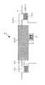
次に、図4を参照してジョグダイヤル4の構造を説明する。図4は、ジョグダイヤル4の回転中心に沿った縦断面図である。
【0078】
ジョグダイヤル4は、円筒状の外周部4aと円環状の天板部4bとがプラスチック成形によって一体に加工され、天板部4bの中心部分に液晶ディスプレイで形成された回転インジケータDSPが一体に固着された構造となっており、筐体に設けられた円筒状の凹断部4cに外周部4aが摺動自在に収容されている。
【0079】
更に、外周部4aの円環状の底面には、外周部4aの底面形状に合わせられた円環状で且つ薄板状に成形されたシール部材SHT1が貼着されると共に、筐体側の凹断部4cの上面には、圧力を感知する誘電体物質で形成された、シール部材SHT1と同形の円環状の圧力感知層THSと、シール部材SHT1と同形の円環状且つ薄板状のシール部材SHT2とが積層されて貼着されている。尚、シール部材SHT1とSHT2は、互いに滑りやすいプラスチックによって成形されている。
【0080】
すなわち、凹断部4bに貼着されたシール部材SHT2に対して、外周部4aの底面に貼着されたシール部材SHT1を摺動自在に接触させつつ、ジョグダイヤル4を凹断部4cに収容することにより、ジョグダイヤル4は凹断部4bに対して回動自在となっており、更に、天板部4b又は回転インジケータDSPがユーザーによって所定の押圧力で筐体側に押圧されると、その押圧力を圧力感知素子としての圧力感知層THSが感知して、その感知結果をシステムコントローラ29に供給する。
【0081】
この結果、ユーザーが予め決められた押圧力でジョグダイヤル4に接触すると、システムコントローラ29がその接触を検知し、回転インジケータDSPの表示を制御するようになっている。
【0082】
尚、本実施形態では、誘電体物質から成る圧力感知層THSの抵抗値の変化等の電気的変化を検知することによって、ユーザーのジョグダイヤル4への接触の有無を検知することとしているが、常開接点又は常閉接点を有する機械式スイッチを用いて、ジョグダイヤル4の接触の有無を検知するようにしてもよい。また、ユーザーがジョグダイヤル4に接触したときの静電容量の変化を検知する静電容量検知センサを用いることも可能である。
【0083】
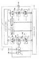
次に、図5を参照して本オーディオ編集装置1の筐体内に備えられているディスク再生部15の構成を説明する。
【0084】
図5において、既述したクランプ位置には、光ディスク13を所定方向に回転させるスピンドルモータ16と、光ディスク13からデータを光学的に読み取って、得られた読取り信号を出力するピックアップ17が設けられ、更にピックアップ17を光ディスク13の半径方向へ往復移動させつつ、適切な光学読み取りを行わせるべくサーボ制御するサーボ機構18が設けられている。
【0085】
更に、ディスク再生部15にはRFアンプ部19とピックアップサーボ回路20が設けられ、RFアンプ部19がピックアップ17から出力される読取り信号からフォーカスエラー信号FEやトラッキングエラー信号TE等の誤差信号を生成すると、ピックアップサーボ回路20がフォーカスエラーやトラッキングエラー等の誤差の発生を抑制すべく、サーボ機構18をフィードバック制御する。また、ピックアップサーボ回路20は、システムコントローラ29から指示された光ディスク13の記録トラックへピックアップ17を移動させるべく、サーボ機構18の動作を制御する。
【0086】
更に、RFアンプ部19は、ピックアップ17から出力される読取り信号から、光ディスク13に記録されていたデータをRF信号DRFとして生成し、オーディオデータデコード部21とコントロールデータデコード部22に供給する。
【0087】
オーディオデータデコード部21は、光ディスク13毎に規格化されているフォーマットに準拠してRF信号DRFをデコードし、RF信号DRF中に含まれているオーディオストリームDASを分離抽出して復号化部23に供給する。更に、復号化部23は、MPEGやAC−3、MP3等の規格によって情報報圧縮されているオーディオストリームDASを復号し、その復号化後の再生データDAU1をバッチ処理部24に供給する。
【0088】
コントロールデータデコード部22は、光ディスク13毎に規格化されているフォーマットに準拠してRF信号DRFをデコードし、RF信号DRF中に含まれているコントロールデータDcを分離抽出し、バッチ処理部24とスピンドルサーボ回路25及びシステムコントローラ29に供給する。
【0089】
ここで、コントロールデータDcとして、オーディオストリームDASに含めて記録されている同期データ及びサブコードデータ等の種々のコントロールデータが分離抽出され、バッチ処理部24にはサブコードデータDSB、スピンドルサーボ回路25には同期データ、システムコントローラ29には全てのコントロールデータDcが供給される。
【0090】
スピンドルサーボ回路25は、システムコントローラ29から指示されたスピンドルモータ16の回転速度に対する同期データの誤差を検出し、その誤差の発生を抑制すべくスピンドルモータ16の回転をフィードバック制御する。
【0091】
バッチ処理部24は、コントロールデータデコード部22から供給されるサブコードデータDSBと復号化部23から供給される再生データDAU1とを対応づけて所定のデータ構造から成るパックデータDPAKを生成し、そのパックデータDPAKから「ビット密度」と呼ばれる新規な情報(以下、「ビット密度データ」という)を生成する。更に、後述のリングバッファメモリ32にパックデータDPAKを記憶させ、システムコントローラ29の制御の下で所謂バッチ処理を行いつつ、リングバッファメモリ32からパックデータDPAKを読み出し、読み出したパックデータDPAKに含まれている再生データDAU1を再生データDAU2として、オーディオ編集部26に供給する。このように、バッチ処理部24が所謂バッチ処理を行うことで、光ディスク13から再生データDAU1とコントロールデータDcを再生するための処理に対して、オーディオ編集部26の処理を実質的に独立させるようになっている。
【0092】
オーディオ編集部26は、バッチ処理部24から供給される再生データDAU2に対して、既述した様々な変調を施すことにより、様々な効果音を付与するためのイフェクト処理(編集処理)を行う。つまり、ユーザーが図1に示した操作キー7a〜7f,8a,8b及びジョグダイヤル4を操作して所望の変調方法を指示すると、その指示された変調方法に応じて再生データDAU2を変調することにより、様々な擬音を付与するためのイフェクト処理を行い、イフェクト処理後のデータ(以下、「イフェクトデータ」という)DEFをオーディオ信号生成部27に供給する。
【0093】
オーディオ信号生成部27は、イフェクトデータDEFをデジタルデータのまま出力したり、A/D変換器(図示省略)によってイフェクトデータDEFを可聴周波数帯域のアナログオーディオ信号に変換してオーディオ出力端子28に出力し、オーディオ出力端子28に接続されたスピーカやマイクロフォン等によって最終的に再生音を鳴動させるようになっている。
【0094】
システムコントローラ29は、マイクロプロセッサ(MPU)を備え、予め設定されているシステムプログラムを実行することにより、本オーディオ編集装置1全体の動作を集中制御する。
【0095】
また、システムコントローラ29は、図4に示した圧力感知層THSから出力される検知データSTHSを入力する。また、ジョグダイヤル4に設けられている回転インジケータDSPに表示データSDSPを供給する。
【0096】
更にまた、システムコントローラ29には、表示部3とメモリカードスロット10と操作部30が接続され、表示部3の表示を制御すると共に、メモリカードスロット10に挿入されたメモリカードとの間でデータの授受を行い、更に、操作部30に設けられている操作キー5a〜5h,6a〜6f,7a〜7f,8a,8bからの指示データを入力し、指示データに応じてディスク再生部15を制御する。更に、ジョグダイヤル4の回転方向及び回転速度(角速度)を検出するロータリエンコーダ回路(図示省略)を備えた角速度検出部31が接続されている。
【0097】
角速度検出部31は、ジョグダイヤル4の回転方向及び回転速度をロータリエンコーダ回路によって光学的に検出し、その検出データSθをシステムコントローラ29に供給する。これにより、システムコントローラ29は、ユーザーが手回し操作したジョグダイヤル4の操作量(回転方向及び角速度)を認識し、オーディオ編集部26に対してその操作量に応じたイフェクト処理を行わせる。
【0098】
更に、システムコントローラ29は、既述した圧力感知層THSからの検知データSTHSと角速度検出部31からの検出データSθを逐一調べ、ジョグダイヤル4に所定の押圧力が付与された状態で回転操作されたと判断すると、角速度検出部31で検出されるジョグダイヤル4の回転方向と角速度に応じて、後述のリングバッファメモリ32に記憶されているパックデータDPAKの読み出しアドレスと読み出しタイミングを制御する。
【0099】
すなわち、ジョグダイヤル4に所定の押圧力が付与されたと判断すると、リングバッファメモリ32に記憶されているパックデータDPAKの読み出しアドレスを一旦固定し、その固定した読み出しアドレスを起点として、ジョグダイヤル4の回転方向に応じて読み出しアドレスを増減し、更にジョグダイヤル4の角速度に応じて読み出しタイミングを変化させる。
【0100】
これにより、ジョグダイヤル4の回転方向と角速度に応じて、リングバッファメモリ32からパックデータDPAKが読み出されてオーディオ編集部26及びオーディオ再生部27に供給されることにより、再生音の音調がジョグダイヤル4の回転方向と角速度に応じて変化する。
【0101】
更にまた、システムコントローラ29は、圧力感知層THSから出力される検知データSTHSと角速度検出部31の検出データSθを逐一調べ、ジョグダイヤル4に所定の押圧力が付与されていないにもかかわらず、停止していたジョグダイヤル4が回動操作されたと判断すると、ジョグダイヤル4の停止中にリングバッファメモリ32からパックデータDPAKを読み出していたときの読み出しアドレスと読み出しタイミングを基準として、ジョダイヤル4の回転方向と角速度に応じて、その基準とした読み出しアドレスと読み出しタイミングを変化させる。
【0102】
つまり、ジョグダイヤル4が操作されることなく停止していると、通常の再生音を生成すべく、所定の読み出しタイミングでリングバッファメモリ32に対する読み出しアドレスを順次に増加させていく。そして、ジョグダイヤル4に所定の押圧力が付与されることなく、停止していたジョグダイヤル4が回転されると、回転直前の読み出しアドレスを起点としてジョグダイヤル4の回転方向に応じて読み出しアドレスを増減し、且つジョグダイヤル4の角速度の分だけ今までの読み出しタイミングを早く又は遅くする。これにより、ビッドベンドを可能にしている。
【0103】
更に、詳細については後述するが、システムコントローラ29は、リングバッファメモリ32に記憶されているパックデータDPAKが不足してくると、新たなパックデータDPAKに更新すべく、ピックアップサーボ回路20とスピンドルサーボ回路25に指示してピックアップ17を移動させ、光ディスク13から更新用のデータを読み取らせるための制御を行う。そして、バッチ処理部24に指示して、更新用のデータから新たなパックデータDPAKを生成させて、リングバッファメモリ32に記憶させる。これにより、不連続な再生音が生成されるのを未然に防止している。
【0104】
次に、図6及び図7を参照して、バッチ処理部24の構成を説明する。
【0105】
図6において、バッチ処理部24には、不発性半導体メモリで形成された所定の記憶容量を有するリングバッファメモリ32と、システムコントローラ29から指定された書き込みアドレスを設定する書込みアドレスコントローラ33と、書込みアドレスコントローラ33で設定されるリングバッファメモリ32のアドレスにパックデータDPAKを書き込むデータ書込み部34と、システムコントローラ29から指定された読み出しアドレスを設定する読出しアドレスコントローラ35と、読出しアドレスコントローラ35で設定されるリングバッファメモリ32のアドレスからパックデータDPAKを読出すデータ読出し部36が備えられている。
【0106】
リングバッファメモリ32は、例えば64MbyteのSDRAMで形成されており、図7(b)に示すように、論理的先頭アドレスAFWから論理的終端アドレスABWまでのデータ記憶領域に、フロント領域Fと主記憶領域Mとリア領域R及び汎用領域NULLが割り当てられている。フロント領域Fは、それぞれn個分のパックデータDPAKを記憶する2つの領域FA,FBからなり、リア領域Rは、それぞれn個分のパックデータDPAKを記憶する2つの領域RA,RBからなり、主記憶領域Mは予め決められた所定数mのパックデータDPAKを記憶するための記憶容量に設定され、汎用領域NULLは任意数のパックデータDPAKを記憶することが可能な記憶容量に設定されている。
【0107】
そして、リングバッファメモリ32を、論理的先頭アドレスAFWと論理的終端アドレスABWとが繋がったエンドレスなものとして扱うことから、図7(c)に示すように、汎用領域NULLの両側に領域FA,FBが位置し、領域FA,FBの間に主記憶領域Mが介在した論理構造となっており、上記のアドレスコントローラ33,35とデータ書込み部34及びデータ読出し部36による制御下で、この論理構造を崩さないように、パックデータDPAKを記憶してから読み出すようになっている。
【0108】
つまり、領域FA,M,FB,NULLには、図7(b)(c)に示す論理構造を崩さないことを条件として相対的にアドレス設定を行って、パックデータDPAKを記憶するようになっている。ただし、汎用領域NULLには、パックデータDPAKを記憶させず、緩衝領域として機能させるようになっている。
【0109】
更に、図6に示したコントロールデータデコード部22からのサブコードデータDSBと復号化部23からの再生データDAU1とを、入力バッファ回路37を介して、システムコントローラ29の指示に従った所定タイミングで入力するパックデータ交換部38が備えられている。
【0110】
パックデータ交換部38は、図7(a)に示すように、サブコードデータDSBと、そのサブコードデータDSBに対応する再生データDAU1とを対応づけたパックデータDPAKを生成する。すなわち、再生データDAU1の経過トラック時間を示すQチャンネルデータをサブコードデータDSBから検出し、検出したQチャンネルデータに対応する再生データDAU1とサブコードデータDSBを対応づけることにより、図7(a)に示すパックデータDPAKを生成するためのデータ交換を行う。そして、順次に形成したパックデータDPAKをデータ書込み部34に供給し、リングバッファメモリ32に記憶させる。
【0111】
また、パックデータ交換部38は、パックデータDPAKをビート密度算出部39供給する。
【0112】
ビート密度算出部39は、図示していない、可聴周波数帯域を高中低の3つの周波数帯域に分割して設定された3つのデジタルフィルタから成る帯域フィルタと、ピークレベル検出部と、波形整形部と、時間窓設定部と、計数部と、ビート位置検出部を備えて構成されている。
【0113】
パックデータDPAK中に含まれている再生データDAU1が帯域フィルタを通過することにより、再生データDAU1の低域と中域と高域の成分が抽出され、各周波数帯域の成分をピークレベル検出部がピーク検出し、更にそれぞれピーク検出された低域と中域と高域の成分を波形整形部が2値の論理データとして波形整形する。これらの各論理データを時間窓設定部で設定される所定期間毎に計数部が計数する。そして、所定期間毎に計数された低域と中域と高域の計数値を、低域におけるビート密度DfLと中域のビート密度DfMと高域のビート密度DfHとして求め、更に、所定の係数βL,βM,βHを乗算して加算することにより得られる値(βL×DfL)+(βM×DfM)+(βH×DfH)を再生データDAU1のビート密度DBTとする。更に、ビート位置検出部が、パックデータDPAK中に含まれているサブコードデータDSB中のQチャンネルデータから経過トラック時間を検出し、その経過トラック時間とビート密度DBTとを対応づけてシステムコントローラ29に供給する。そして、システムコントローラ29が、上記の経過トラック時間とビート密度DBTとを表示部3に供給して、経過トラック時間に対するビート密度DBTとして表示させることで、スピーカ等で再生される再生音のビート密度をユーザーに提供するようになっている。
【0114】
更に、既述したデータ読出し部36に続いて、パックデータ分離部40と再生位置検出部41が設けられている。
【0115】
パックデータ分離部40は、リングバッファメモリ32からデータ読出し部36を介して読み出されたパックデータDPAKが供給され、そのパックデータDPAKに含まれているサブコードデータDSBと再生データDAU1を分離する。そして、サブコードデータDSBを再生位置検出部41へ供給し、再生データDAU1を再生音生成用の再生データDAU2として、図5に示したオーディオ編集部26へ供給する。
【0116】
再生位置検出部41は、サブコードデータDSB中のQチャンネルデータを抽出することにより、再生データDAU2がオーディオ編集部26とオーディオ信号生成部27で処理されて最終的にスピーカやヘッドフォンで再生音として再生される時点(現時点)での経過トラック時間を検出し、その検出した経過トラック時間データDPQをシステムコントローラ29に供給する。
【0117】
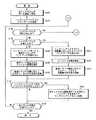
次に、かかる構成を有する本オーディオ編集装置1の動作を、図8乃至図13を参照して説明する。尚、図8及び図9は本オーディオ編集装置1の動作を説明するためのフローチャート、図10乃至図13は、リングバッファメモリの動作を示す説明図である。
【0118】
図8において、ユーザーがディスク挿入口14を介して光ディスク13を挿入し、操作部30から再生開始の指示をすると、システムコントローラ29の制御下でディスク再生部15が再生動作を開始する。
【0119】
まず、ステップS100において、スピンドルモータ16及びピックアップ17が起動し、光ディスク13からのデータ読取りを開始する。
【0120】
更にステップS102において、パックデータ交換部38が、順次に読み取られたデータに含まれているサブコードデータDSBと再生データDAU1とを対応付けてパックデータDPAKを生成し、そのパックデータDPAKを順次にリングバッファメモリ32のフロント領域Fと主領域Mとリア領域Rに記憶させていく。より具体的には、図7(b)に示したように、上記領域Fからリア領域Rにかけて、(2×n+m+2×n)個のパックデータDPAKを記憶させる。
【0121】
更に、パックデータDPAKを順次にリングバッファメモリ32に記憶させる際に、ビート密度データDBTを生成してシステムコントローラ29に供給し、更に、システムコントローラ29がビート密度データDBTを表示部3に供給して表示させる。
【0122】
次に、ステップS104においてジョグダイヤル4が所定の押圧力で押されたか否か調べ、押圧されていなければステップS106において更に、ジョグダイヤル4が回動されたか否か調べ、回動されていなければステップS108へ移行し、回動されていればステップS114へ移行する。
【0123】
つまり、ユーザーがジョグダイヤル4に接触しなかったり、接触したとしても所定の押圧力より小さい力でジョグダイヤル4に接触しただけで回動操作しなかった場合には、ステップS108に処理が移行し、ユーザーが所定の押圧力より小さい力でジョグダイヤル4に接触しつつ回動させた場合(すなわちビッドベンドが行われたとき)には、ステップS114に処理が移行する。
【0124】
尚、ステップS104においてジョグダイヤル4が所定の押圧力で押された場合には、図9に示す後述のステップS200の処理に移行する。
【0125】
ステップS108に移行すると、システムコントローラ29がリングバッファメモリ32の読出しアドレスを指定し、その指定した読出しアドレスのパックデータDPAKをリングバッファメモリ32から読み出す。ここで、システムコントローラ29は、再生位置検出部41から供給される1つ前の経過トラック時間データDPQを調べ、指定すべき次の読出しアドレスを決定する。そして、アドレスコントローラ35に指示して上記の決定した読出しアドレスを設定させ、リングバッファメモリ32からデータ読出し部36を介してパックデータDPAKを読み出す。更に、光ディスク13毎に決められている標準の再生タイミングでリングバッファメモリ32をメモリアクセスすることによってパックデータDPAKを読み出す。
【0126】
次に、ステップS110において、パックデータ分離部40が、読み出されたパックデータDPAKから再生データDAU1とサブコードデータDSBとを分離し、再生データDAU1を再生音生成用の再生データDAU2としてオーディオ編集部26に供給すると共に、サブコードデータDSBを再生位置検出部41に供給する。
【0127】
これにより、オーディオ編集部26が、操作部30に設けられている操作キー7a〜7f,8a,8bで指定されている変調方法に従って再生データDAU2をイフェクト処理し、更にオーディオ信号生成部27からアナログオーディオ信号が出力される。更に、再生位置検出部41がサブコードデータDSB中のQチャンネルデータから経過トラック時間データDPQを生成してシステムコントローラ29に供給する。
【0128】
次に、ステップS112において、システムコントローラ29が、経過トラック時間データDPQに応じて、回転インジケータDSPに設けられている表示部DSP1の回転表示領域Xと表示部DSP2の扇表示領域Yを点灯させる。こうして表示部DSP1の回転表示領域Xを表示制御することにより、あたかも正転しているアナログレコードを見ているような操作感をユーザーに提供し、更に、表示部DSP2の扇表示領域Yによって、未再生の残存データ量をアナログ表示する。
【0129】
また、ステップS108〜S112の処理では、ジョグダイヤル4が停止したままの状態であるため、光ディスク13毎に決められている標準の再生タイミングに従って再生音を生成することになる。
【0130】
一方、ステップS106からステップS114に処理が移行した場合、ステップS114において、システムコントローラ29がリングバッファメモリ32の読出しアドレスを指定し、その指定した読出しアドレスのパックデータDPAKをリングバッファメモリ32から読み出す。ここで、システムコントローラ29は、再生位置検出部41から供給される1つ前の経過トラック時間データDPQを調べ、指定すべき次の読出しアドレスを決定する。そして、アドレスコントローラ35に指示して上記の決定した読出しアドレスを設定させ、リングバッファメモリ32からデータ読出し部36を介してパックデータDPAKを読み出す。更に、ジョグダイヤル4の回動量(回転方向及び角速度)に応じたタイミングでリングバッファメモリ32をメモリアクセスすることによってパックデータDPAKを読み出す。
【0131】
次に、ステップS116において、パックデータ分離部40が、読み出されたパックデータDPAKから再生データDAU1とサブコードデータDSBとを分離し、再生データDAU1を再生音生成用の再生データDAU2としてオーディオ編集部26に供給すると共に、サブコードデータDSBを再生位置検出部41に供給する。
【0132】
ただし、ここでは、オーディオ編集部26はイフェクト処理を停止し、オーディオ信号生成部27もアナログオーディオ信号の出力を停止する。更に、再生位置検出部41がサブコードデータDSB中のQチャンネルデータから経過トラック時間データDPQを生成してシステムコントローラ29に供給する。
【0133】
次に、ステップS118において、システムコントローラ29が、経過トラック時間データDPQに応じて、回転インジケータDSPに設けられている表示部DSP1の回転表示領域Xと表示部DSP2の扇表示領域Yを点灯させ、更に、ジョグダイヤル4の回転量に応じて変化する経過トラック時間データDPQに応じて、指標表示部INDX2〜INDX7を点滅させる。
【0134】
こうして指標表示部INDX2〜INDX7を表示制御することにより、あたかもアナログレコードをビットベンドしたような操作感を提供し、更に、表示部DSP1の回転表示領域Xと表示部DSP2の扇表示領域Yとを制御することによって、アナログレコードを見ているような操作感を提供すると共に、未再生の残存データ量を表示する。
【0135】
つまり、ステップS114〜S118の処理では、ユーザーがジョグダイヤル4をビットベンドした場合の処理を行うようになっている。
【0136】
次に、ステップS112又はS118の処理が終わってステップS120に処理が移行すると、システムコントローラ29が、リングバッファメモリ32中に記憶されているパックデータDPAKが不足したか判断する。すなわちリングバッファメモリ32中に記憶されているパックデータDPAKを順次に読み出した結果、リングバッファメモリ32の読出しアドデスが論理的終端アドレスABW側に近づいてしまい、このままパックデータDPAKを順次に読み出すと、再生音を生成するのに十分なパックデータDPAKが残されていないことになるのか否かを判断する。
【0137】
ここで、再生音を生成するのに十分なパックデータDPAKがリングバッファメモリ32中に残っていると判断した場合には、ステップS124に移行する。リングバッファメモリ32中に記憶されているパックデータDPAKが不足している判断した場合には、ステップS122に移行し、リングバッファメモリ32中に記憶されているパックデータDPAKを新たなパックデータDPAKで更新するための更新処理を行う。
【0138】
ここで、ステップS122の更新処理は次のようにして行われる。例えば、更新前のリングバッファメモリ32には、図10(a)及び図11(a)に示すように、光ディスク13のプログラム領域の或る範囲DW1から読み取ったデータから生成したパックデータDPAKが記憶されており、図10(a)に示す領域RBの或る読出しアドレスtch1を設定することになると、パックデータDPAKが不足したと判断する。つまり、読出しアドレスtch1が、論理的終端アドレスABWに近い領域RBに位置することになると、パックデータDPAKが不足したと判断する。
【0139】
そして、図10(a)及び図11(a)の領域RAとRBのパックデータDPAKをそのままにしておき、図10(b)及び図11(b)に示すように、更新後の領域FAとFBのパックデータDPAKとして更新する。更に、更新後の領域FBのパックデータDPAKに含まれている再生データDAU1に連続性を持って続けるべきデータをピックアップ17によって光ディスク13から読み取り、読み取ったデータから新たに生成したパックデータDPAKを、更新後の領域FBの後ろから順次に上書き記憶させる。これにより、図10(b)及び図11(b)に示すように、更新後の領域FA,FBの後ろに更新後の主領域Mと領域RA,RBが生じることになる。
【0140】
ここで、更新前の領域RA,RBのパックデータDPAKを更新後の領域FA,FBのパックデータDPAKとするので、更新後の主領域Mと領域RA,RBにパックデータDPAKを記憶する分だけのデータ、すなわち、図10に示す光ディスク13の範囲DW2のデータだけをピックアップ17で読み取ることにより、更新処理の迅速化を実現している。
【0141】
このように更新処理を行うと、更新前の領域RA,RBのパックデータDPAKが更新後の領域FA,FBに残されることになるため、読出しアドレスコントローラ36によってアドレスtch1から続いて順次にアドレス設定がなされて、読み出されたパックデータDPAKに基づいて再生音を生成した場合でも、その再生音は不連続に途切れることがない。このため、品質の良い再生音を提供することが可能となっている。
【0142】
また、図10(b)及び図11(b)のようにリングバッファメモリ32を更新した後、更に図10(b)に示す領域RB中の読出しアドレスtch2を設定することになって、パックデータDPAKが不足することになった場合にも、図10(a)及び図11(a)の状態から図10(b)及び図11(b)の状態に更新したのと同様の更新処理が行われることにより、リングバッファメモリ32は、図10(b)及び図11(b)の状態から図10(c)及び図11(c)の状態に更新される。そして、この図10(c)及び図11(c)の状態に更新する際にも、更新後の主領域Mと領域RA,RBに記憶させるためのデータだけ、すなわち、図10に示す光ディスク13の範囲DW3のデータだけを光ピックアップ17が読み取ることで更新処理の迅速化を実現し、更に、更新後の領域FA,FBにパックデータDPAKが残されることになるため、品質の良い再生音を提供することができるようになっている。
【0143】
こうして、リングバッファメモリ32に新たなパックデータDPAKを更新し終えると、ステップS124に移行する。
【0144】
ステップS124では、全トラックの再生が完了したか否か判断し、未だであればステップS104からの処理を繰り返し、完了していれば処理を終了する。
【0145】
次に、上記ステップS104から図9のステップS200に移行した場合の動作を説明する。
【0146】
ステップS200では、ジョグダイヤル4が回動操作されたか否か判断する。すなわち、図8中のステップS104において、ジョグダイヤル4が押圧操作されたと判断した後、ステップS200でジョグダイヤル4が回動操作されたか否か判断することにより、ジョグダイヤル4が押圧されただけで回動操作されることなく停止したままの状態となっているのか、ジョグダイヤル4が押圧されつつ回動操作されているのかを判断する。
【0147】
ジョグダイヤル4が押圧されただけで回動操作されることなく停止したままの状態となっていると判断すると、ステップS202の処理に移行し、ジョグダイヤル4が押圧されつつ回動操作されていると判断すると、ステップS208の処理に移行する。
【0148】
ステップS202に移行すると、リングバッファメモリ32からのパックデータDPAKの読み出しを停止し、更にステップS204においてイフェクト処理を停止する。
【0149】
次に、ステップS206において、表示部DSP4を点灯させることで、ジョグダイヤル4の回転が停止していることを表示する。更に、表示部DSP1とDSP2の表示を現状のまま、すなわちジョグダイヤル4が押圧操作された直前の状態のままにする。
【0150】
このように、表示部DSP4を点灯させ、表示部DSP1とDSP2の表示を現状のまま維持することにより、あたかもアナログレコードに接触して回転を停止させたのと同様の操作感を提供するようになっており、更に、イフェクト処理を停止することにより、再生音の出力も停止することで、アナログレコードの回転を停止させて再生音が出力されない状態と同様の操作感を提供するようになっている。
【0151】
一方、ステップS200からステップS208に処理が移行すると、ステップS208〜S212の処理によって、ジョグダイヤル4の回動量(回転方向及び角速度)に応じたイフェクト処理が行われる。
【0152】
まず、ステップS208では、システムコントローラ29がリングバッファメモリ32の読出しアドレスをジョグダイヤル4の回動量(回転方向及び角速度)に応じて指定し、その指定した読出しアドレスのパックデータDPAKをリングバッファメモリ32から読み出す。ここで、システムコントローラ29は、再生位置検出部41から供給される1つ前の経過トラック時間データDPQを調べ、指定すべき次の読出しアドレスを決定する。そして、アドレスコントローラ35に指示して上記の決定した読出しアドレスを設定させ、リングバッファメモリ32からデータ読出し部36を介してパックデータDPAKを読み出す。更に、ジョグダイヤル4の回転量(回転方向及び角速度)に応じたタイミングでリングバッファメモリ32をメモリアクセスすることによってパックデータDPAKを読み出す。
【0153】
したがって、例えば、図7(b)に示した主領域M中のアドレスADRをアドレス設定したときにジョグダイヤル4が押圧操作されて時計回り方向へ回転されると、システムコントローラ29が、アドレスADRを始点として、ジョグダイヤル4の角速度分に対応するアドレスを増加していき、読出しアドレスコントローラ35によって設定されるアドレスが論理的終端アドレスABW側へ順次に移動し、フォワード再生の状態になる。そして、読出しアドレスコントローラ35によって設定されるアドレスからパックデータDPAKが読み出される。
【0154】
また、ジョグダイヤル4が反時計回り方向へ回転されると、システムコントローラ29が、アドレスADRを始点として、ジョグダイヤル4の角速度分に対応するアドレスを減少させていき、読出しアドレスコントローラ35によって設定されるアドレスが論理的先頭アドレスAFW側へ順次に移動し、リバース再生の状態になる。そして、読出しアドレスコントローラ35によって設定されるアドレスからパックデータDPAKが読み出される。
【0155】
また、ジョグダイヤル4が時計回り方向と反時計回り方向へ往復操作されると、アドレスADRを始点として、フォワード再生とリバース再生とが交互に変化する状態となり、アドレスADRを始点として読出しアドレスが増減して、パックデータDPAKが読み出される。
【0156】
尚、領域FA,FB,M,RA,RBの夫々の記憶容量は、ユーザーがジョグダイヤル4を時計回り方向と反時計回り方向へ往復操作する際の一般的な最大回動角の分よりも多くのパックデータDPAKを記憶できるように予め決められているため、ジョグダイヤル4の回転に応じてリングバッファメモリ32に記憶されているパックデータDPAKを読み出すことが可能となっている。
【0157】
次に、ステップS210において、パックデータ分離部40が、読み出されたパックデータDPAKから再生データDAU1とサブコードデータDSBとを分離し、再生データDAU1を再生音生成用の再生データDAU2としてオーディオ編集部26に供給すると共に、サブコードデータDSBを再生位置検出部41に供給する。
【0158】
この結果、オーディオ編集部26は操作キー7a〜7f,8a,8bで指定されたイフェクト処理及びジョグダイヤル4の回動量に応じたイフェクト処理を行い、オーディオ信号生成部27がアナログオーディオ信号を出力する。
【0159】
つまり、ジョグダイヤル4が時計回り方向へ回転されると、その回転速度に応じて順方向に読み出された再生データDAU2に基づいて、変調された擬音が出力されることになり、ジョグダイヤル4が反時計回り方向へ回転されると、その回転速度に応じて逆方向に読み出された再生データDAU2に基づいて、変調された擬音が出力されることになる。また、ジョグダイヤル4が時計回り方向と反時計回り方向へ往復操作されると、その回転速度に応じて順方向と逆方向に読み出された再生データDAU2に基づいて、変調された擬音(スクラッチ音)が出力されることになる。
【0160】
更に、再生位置検出部41がサブコードデータDSB中のQチャンネルデータから経過トラック時間データDPQを生成してシステムコントローラ29に供給する。
【0161】
次に、ステップS212において、システムコントローラ29が、表示部DSP4を点灯させることで、ジョグダイヤル4が押圧されていることを表示する。更に、経過トラック時間データDPQに応じて、回転インジケータDSPに設けられている表示部DSP1の回転表示領域Xと表示部DSP2の扇表示領域Yを点灯させる。
【0162】
このように、ステップS208〜S212の処理を行うことで、回動操作されたジョグダイヤル4の回動量に応じた擬音を出力し、特に、ジョグダイヤル4が往復操作されると、スクラッチ音を生成して出力するようになっている。
【0163】
更に、表示部DSP4を点灯させることで、あたかもアナログレコードを押圧しながら手回し操作しているような操作感を提供し、更に、表示部DSP1の回転表示領域Xと表示部DSP2の扇表示領域Yの表示制御によって、アナログレコードを見ているような操作感を提供するとともに、未再生の残存データ量を表示する。
【0164】
次に、ステップS206又はS212の処理が終わってステップS214に処理が移行すると、システムコントローラ29が、リングバッファメモリ32中に記憶されているパックデータDPAKが不足したか判断する。すなわちリングバッファメモリ32中に記憶されているパックデータDPAKを順次に読み出した結果、リングバッファメモリ32の読出しアドデスが論理的終端アドレスABW側に近づいてしまい、このままパックデータDPAKを順次に読み出すと、再生音を生成するのに十分なパックデータDPAKが残されていないことになるのか否かを判断する。
【0165】
ここで、再生音を生成するのに十分なパックデータDPAKがリングバッファメモリ32中に残っていると判断した場合には、ステップS218に移行し、リングバッファメモリ32中に記憶されているパックデータDPAKが不足している判断した場合には、ステップS216に移行し、リングバッファメモリ32中に記憶されているパックデータDPAKを新たなパックデータDPAKで更新するための更新処理を行う。
【0166】
尚、ステップS216の更新処理は、図10及び図11を参照して説明した図8中のステップS122と同様に行われる。
【0167】
更に、図8中のステップS122の説明では、フォワード再生の際の更新処理について説明したが、ジョグダイヤル4が反時計回り方向へ回転されてリバース再生が行われた結果、リングバッファメモリ32に記憶されているパックデータDPAKが不足した場合には、次のようにして更新処理が行われる。
【0168】
つまり、例えば図12(a)及び図13(a)に示すように、光ディスク13のプログラム領域の或る範囲DR1のデータから生成されたパックデータDPAKがリングバッファメモリ32に記憶されていて、論理的先頭アドレスAFWに近い領域FAに読出しアドレスtch3がくると、リバース再生時の更新処理が行われる。そして、図12(b)及び図13(b)に示すように、フロント領域Fの領域FA,FBに記憶されているパックデータDPAKはそのままにして、それらの領域FA,FBを更新後の領域RA,RBに設定し、更に、更新後の領域RA,RBに続けて汎用領域NULLを設定する。
【0169】
更に、更新後の領域FA,FBと主領域MにパックデータDPAKを記憶させるために必要なデータを光ディスク13の範囲DR2から読み取り、読み取ったデータに含まれている再生データDAU1とサブコードデータDSBとから新たに生成したパックデータDPAKを、汎用領域NULL以降のアドレスに順次に記憶していく。これにより、図12(a)及び図13(a)の状態となっていた更新前のリングバッファメモリ32は、図12(b)及び図13(b)の状態に更新され、汎用領域NULLに続いて更新後の領域FA,FBと主領域Mが設定される。
【0170】
このように、リバース再生時の更新処理においても、フロント領域Fの領域FA,FBに記憶されているパックデータDPAKを更新後の領域RA,RBとして設定して、範囲DR2から更新後の領域FA,FBと主領域Mに記憶させるべきデータだけを読み取るので、フォワード再生時の更新処理の場合と同様に、更新処理の迅速化を図るになっている。
【0171】
こうしてステップS216において、ジョグダイヤル4の操作量に応じたフォワード再生又はリバース再生が行われ、更に、必要に応じてフォワード再生時の更新処理又はリバース再生時の更新処理が行われることで、所謂スクラッチ音と呼ばれる擬音が再生されることになる。そして、ステップS218に移行する。
【0172】
ステップS218では、全トラックの再生が完了したか否か判断し、未だであれば図8中のステップS104からの処理を繰り返し、完了していれば処理を終了する。
【0173】
以上説明したように本実施形態は、ユーザーがジョグダイヤル4を所定の押圧力で押圧しつつ回動操作すると、ジョグダイヤル4の回動量に応じたイフェクト処理を行うので、あたかもアナログレコードを操作しているのと同様の操作感を提供することが可能となっている。また、ジョグダイヤル4に設けられた回転インジケータDSPによって、ジョグダイヤル4の回動量を表示するので、ユーザーがその表示を見るだけで、あたかもアナログレコードの動きを見ているかのような効果感を得ることができるようになっている。
【0174】
このため、CDやDVD等の光ディスクを用いて再生音に様々な編集を施す際に、アナログレコードを操作して編集を行っているのと同様の操作感をユーザーに提供することができる。
【0175】
尚、本実施形態では、CDやDVDに記憶されているデータを再生する場合について説明したが、本発明は特にストレージ媒体にのみ適当可能といものではなく、例えば他のストレージ媒体としてMD(Mini Disc)やハードディスクに記憶されている情報を再生する際にも適用することができ、また、メモリカード等の固体メモリを備えたストレージ媒体に記憶されている情報を再生する際にも適用することができる。
【0176】
【発明の効果】
以上説明したように本発明の情報再生装置によれば、再生すべき情報の情報量を回転体の回転量に応じて設定するので、例えばユーザーが回転体を手回し操作すると、あたかもアナログレコードを手回し操作して再生すべき情報を設定するのと同様の操作感を得ることを可能にする。
【0177】
また、回転体の回転量に応じて、再生すべき情報の再生量を設定して効果音を付与するための処理を行うようにしたしたので、ユーザーが回転体を手回し操作すると、あたかもアナログレコードを手回し操作して、効果音を付与するための操作を行っているかのような操作感が得られることを可能にする。
【0178】
また、検出した回動量から回転体が停止していると判断すると、効果音を付与するための編集処理を停止させることとしたので、ユーザーが回転体に接触しても回転操作しなければ、あたかもアナログレコードを手操作によって強制的に停止させたのと同様の操作感が得られることを可能にする。
【0179】
また、検出した回動量から回転体が正転と逆転との往復回転がなされていると判断すると、回転体が正転している時の回動量に応じて順方向に効果音を付与する編集処理と、回転体が逆転している時の回動量に応じて逆方向に効果音を付与する編集処理とを行わせることとしたので、ユーザーはあたかもアナログレコードを正転と逆転との往復回転させてスクラッチ音を発生させるのと同様の操作感が得られることを可能にする。
【0180】
また、検出した回動量に応じて、回転体の回動量を示す表示を行う表示手段を備えたので、ユーザーが表示手段の表示を見ることで、あたかもアナログレコードを回動操作したときのアナログレコードの動きを見ているかのような操作感が得られることを可能にする。
【図面の簡単な説明】
【図1】本実施形態のオーディオ編集装置の外観構成を示す図である。
【図2】オーディオ編集装置に備えられたジョグダイヤルの上面に形成されている回転インジケータの形状を示す平面図である。
【図3】回転インジケータの表示形態を説明するための図である。
【図4】ジョグダイヤルの構造を示す縦断面図である。
オーディオ編集装置に備えられたディスク再生部の構成を示すブロック図である。
【図5】ディスク再生部に設けられたバッチ処理部の構成を示すブロック図である。
【図6】バッチ処理部の構成を示すブロック図である。
【図7】バッチ処理部に設けられたリングバッファメモリの構成を示す図である。
【図8】オーディオ編集装置の動作を説明するためのフローチャートである。
【図9】オーディオ編集装置の動作を更に説明するためのフローチャートである。
【図10】リングバッファメモリに記憶されるパックデータの更新処理を説明するための図である。
【図11】更にリングバッファメモリに記憶されるパックデータの更新処理を説明するための図である。
【図12】更にリングバッファメモリに記憶されるパックデータの更新処理を説明するための図である。
【図13】更にリングバッファメモリに記憶されるパックデータの更新処理を説明するための図である。
【符号の説明】
1…オーディオ編集装置、4…ジョグダイヤル、13…光ディスク、
15…ディスク再生部、24…バッチ処理部、26…オーディオ編集部、
29…システムコントローラ、31…角速度検出部、
32…リングバッファメモリ、33…書込みアドレスコントローラ、
34…データ書込み部、35…読出しアドレスコントローラ、
36…データ読出し部、38…パックデータ交換部、
40…パックデータ分離部、41再生位置検出部、THS…圧力感知層、
DSP…回転インジケータ[0001]
BACKGROUND OF THE INVENTION
The present invention relates to an information reproducing apparatus that reproduces audio information such as music and voice by applying an effect effect.
[0002]
[Prior art]
Conventionally, an analog record such as LP is played by an analog record player, and during the playback, the rotation direction and rotation speed of the analog record are forcibly changed to give various effect effects to the playback sound. Production techniques are known.
[0003]
For example, as a scene seen at Discotech etc., a director called a disc jockey touches an analog record being played by an analog record player and forcibly rotates it at a speed different from the original rotation speed. By rotating in the reverse direction, various sound effects such as a so-called “scratch sound” (sound such as “Cucu” and “Gasha Gasha”) are generated.
[0004]
[Problems to be solved by the invention]
However, with the advancement of digital technology, storage media such as CDs (Compact Discs) and DVDs (Digital Versatil Discs) on which information is digitally recorded have become widespread, and these storage media can be used in the same way as conventional analog records. It is difficult to obtain an effect effect by operation.
[0005]
That is, in the case of an analog record, audio signals such as music are continuously recorded as they are along the recording track, so that the reproduction position (scanning position) of the analog record by the record needle and the reproduced sound are one-to-one. Therefore, it is possible to obtain a desired effect effect by manual operation.
[0006]
However, in the case of a storage medium such as a CD or DVD in which information is digitally recorded, information recording and information reproduction are performed by a special digital technique that cannot be intuitively understood by human senses. Even if the CD being played is handled manually as in the case of an analog record, there is a problem that a desired effect effect cannot be obtained.
[0007]
In particular, CD players and DVD players are stipulated by the standard to read information while rotating a CD or DVD in a predetermined direction with respect to a pickup which is an optical reading device, and generate reproduced sound. It is not standardized to generate reproduced sound by reading information in the reverse order while rotating a CD or DVD in the reverse direction. For this reason, even if the CD or DVD is simply rotated in the direction opposite to the predetermined direction by manual operation, proper information reading and reproduction cannot be performed. could not.
[0008]
The present invention has been made in view of such conventional problems. For example, an effect effect can be obtained with the same feeling as operating an analog record using a storage medium on which digital recording such as a CD or a DVD is made. An object of the present invention is to provide an information reproducing apparatus that enables the above.
[0009]
[Means for Solving the Problems]
In order to achieve the above object, according to the first aspect of the present invention, there is provided an information reproducing apparatus for reproducing audio information, a storage means for storing the audio information, a disk-shaped rotating body provided rotatably, Detecting means for detecting a stop of the rotating body and detecting a rotating direction and an angular velocity of the rotating body when the rotating operation is performed; and detecting means for detecting whether the rotating body is pressed with a predetermined force or more. Reproducing means for reproducing the audio information stored in the storage means;Control means for controlling the reproduction means, the control means, The detecting means detects that the rotating body has been pressed with a predetermined force or more, and the detecting means detects the rotational direction and angular velocity of the rotating body.Then, the audio information stored in the storage means is read out, an editing process is performed in which a sound effect according to the detected rotation direction and angular velocity is given to the audio information, and the audio information subjected to the editing process Is reproduced by the reproducing means, Further, the detecting means does not detect that the rotating body has been pressed with a predetermined force or more, and the detecting means detects the rotational direction and angular velocity of the rotating body.In this case, with the position of the audio information being played back by the playback means as the reference position, the position of the audio information to be played is jumped according to the detected rotation direction and angular velocity, and the jump is performed. Playing back the audio information by the playback means from a later position; It is characterized by.
[0019]
DETAILED DESCRIPTION OF THE INVENTION
Embodiments of the information reproducing apparatus of the present invention will be described below with reference to the drawings. Note that the information reproducing apparatus of the present embodiment can give various effect (editing) effects to the reproduction information, and will be hereinafter referred to as an audio editing apparatus.
[0020]
1A and 1B are diagrams showing an external configuration of the
[0021]
In FIG. 1A, an
[0022]
As shown in FIG. 1B, a memory 9 having a slit-shaped opening for detachably inserting a memory card incorporating a semiconductor memory is provided on a side surface 9 viewed from the front of the housing of the
[0023]
When an optical disk is inserted into the disk insertion slot 14, an auto loading mechanism (not shown) provided at the back of the disk insertion slot 14 is automatically activated to provide a clamp provided substantially below the
[0024]
Further, when the pressed operation key 5a is pressed again, the rotation of the spindle motor 16 is stopped and the reproducing operation of the optical disk by the
[0025]
The
[0026]
Here, the configuration of the
[0027]
When the user appropriately changes the rotation direction and rotation speed of the
[0028]
The above-described forward reproduction refers to reproducing data on an optical disc in the order of recorded streams, as in the case where music or the like is reproduced by rotating an analog record such as LP in the normal direction. Accordingly, in response to the
[0029]
The reverse playback means that the data on the optical disc is played back in the reverse order of the recorded stream, as in the case of playing music or the like by rotating the analog record in the reverse direction. . In other words, music etc. are recorded continuously (analog recording) in the analog record, so if the analog record is rotated in the reverse direction, the music will be played in the reverse direction, which is different from the original music etc. On the other hand, when the
[0030]
However, the
[0031]
As described above, since a function similar to that for reverse playback of an analog record is provided, for example, a user such as a so-called disc jockey reciprocates in the clockwise and counterclockwise directions by manually turning the
[0032]
The operation keys 5c, 5d, and 5e are called cue buttons. When the user presses the operation key 5c during reproduction of the optical disk, the
[0033]
When the user presses the operation key 5d, the history information stored in the
[0034]
The
[0035]
The operation key 5f is provided for instructing the
[0036]
Although the detailed description of the remaining operation keys 6f to 6h is omitted, it is provided for the user to appropriately select and specify various functions provided in the
[0037]
The operation keys 7a to 7f are provided for instructing the
[0038]
Here, the function of the operation keys 7a and 7b will be described as a representative example. The operation keys 7a and 7b are both formed by a three-stage switching type rotary switch, and are provided with a “first designated position” and a “second designated position” provided for designating an effect processing method, In order to cancel the effect process, the user can appropriately switch the three positions “OFF position” provided between the first and second designated positions.
[0039]
When the operation key 7a is switched to the “first designated position”, the
[0040]
As described above, when the user appropriately switches the operation keys 7a to 7f, editing (effects) for adding various sound effects to the original reproduced sound can be performed, and the
[0041]
The operation key 8a is provided to adjust the volume of the reproduced sound output from the speaker or the headphones, and is provided in the audio signal generation unit 27 in FIG. 5 according to the operation amount of the operation key 8a. Volume adjustment is performed by adjusting the gain of a power amplifier (not shown). The volume is increased when the operation key 8a is pushed away from the user, and the volume is decreased when the operation key 8a is pulled toward the user.
[0042]
The operation key 8b is provided for adjusting the tone of the reproduced sound output from the speaker or the headphones. That is, when the operation key 8b is pushed away from the user, the tempo of the playback sound is increased according to the pushed operation amount, and when the operation key 8b is pulled toward the user, the drawn operation amount. The playback tempo is lowered accordingly. That is, the playback sound tempo is changed by fast-forward playback or slow-forward playback of the playback sound according to the operation amount of the operation key 8b.
[0043]
The adjustment of the tempo of the reproduction sound is realized by adjusting the timing at which the reproduction data is read from the ring buffer memory (see FIG. 6) 32 provided in the
[0044]
When the operation key 8b is pushed away from the user, data is read at an early timing according to the operation amount, and when pulled toward the user, the data is read at a later timing according to the operation amount. Do.
[0045]
The reproduction data read at a timing according to the operation amount of the operation key 8b is supplied to the audio signal generation unit 27 through the audio editing unit 26, and a D / A converter (not shown) provided in the audio signal generation unit 27 is provided. ) Is converted from digital to analog at a predetermined sampling frequency and supplied to the power amplifier, the sampling rate of the D / A converter is substantially changed, and output from the power amplifier to a speaker, headphones, etc. The tempo of the playback sound that is played back with is changed.
[0046]
On the upper surface of the
[0047]
The rotation indicator DSP is formed of a color liquid crystal display, and as shown in FIG. 2, a first display unit DSP1 formed by arranging a large number of rectangular light-emitting cells in an annular shape, A second display portion DSP2 formed by a large number of rectangular light emitting cells arranged in a ring shape inside the first display portion DSP1, and a circular shape formed inside the second display portion DSP2. A third display unit DSP3 and a fourth display unit DSP4 provided close to the inside of the second display unit DSP2 are further provided.
[0048]
Further, a plurality of triangular indicator display parts INDX1 to INDX7 are provided in a predetermined part outside the first display part DSP1, and a predetermined part between the second display part DSP2 and the third display part DSP3. In addition, a triangular index display section INDX8 is provided.
[0049]
Here, a display mode of the rotation indicator DSP will be described with reference to FIG.
[0050]
First, the display mode of the first display unit DSP1 and the index display units INDX1 to INDX7 will be described in comparison with the operation when the analog code is reproduced by the analog record player.
[0051]
As schematically shown in FIG. 3A, when playback is started with the playback arm ARM placed on the analog record placed on the turntable of the analog record player, the analog record is moved in the direction of the arrow θf (clockwise direction). ).
[0052]
In the
[0053]
For this reason, when the user looks at the index display section INDX1, it is possible to obtain an operational feeling as if an analog record is being reproduced by the record needle PIN.
[0054]
Next, as shown in FIG. 3B, among the many display cells constituting the first display unit DSP1, only a plurality of display cells in a relatively narrow angle range in the circumferential direction are lit. A fan-shaped rotation display region X is defined by the plurality of display cells that are turned on, and the remaining display cells are turned off.
[0055]
When the
[0056]
That is, as the analog record rotates in the normal rotation direction θf at 33 rotations per minute as shown in FIG. 3A, the rotation display area X shown in FIG. 3B also rotates at 33 rotations per minute. To move in the clockwise direction θf. Therefore, just by looking at the rotation display area X that rotates and moves along the annular first display portion DSP1, the user can obtain the same operational feeling as if he / she saw the rotating analog record. ing.
[0057]
Next, if the user rotates the
[0058]
Therefore, the user manually turns the
[0059]
Next, when the user rotates the
[0060]
Therefore, when the user turns the
[0061]
Next, as shown by a bidirectional arrow θfr in FIG. 3B, when the user reciprocates in the clockwise direction and the counterclockwise direction by a hand turning operation while applying a predetermined pressing force to the
[0062]
Next, the index display parts INDX2 to INDX7 will be described. When the user manually operates the
[0063]
For example, when a disc jockey is playing an analog record with an analog record player, a disc jockey instantaneously puts it on a turntable that rotates at a predetermined speed while placing the analog record. By touching and applying an external force only for a short time, an operation is performed such that the turntable is normally rotated earlier than the predetermined rotational speed, or the turntable is normally rotated later than the predetermined rotational speed. There is a case. Such an operation is called “bit bend”, and is a method used to finely adjust the contact position of the record needle with respect to the analog record. For example, the phase of the other music etc. is matched with one music etc. reproduced by two analog record players (in other words, the tempo of one music etc. is matched with the tempo of the other music etc.) When making fine adjustments, the disc jockey makes one of the two analog record players bit bend so that the two music played on the two analog record players can be heard without any sense of incongruity There is a case where the production is performed.
[0064]
In the
[0065]
That is, when the
[0066]
When the bit bend is made to the
[0067]
When the
[0068]
Furthermore, according to the amount of clockwise rotation of the
[0069]
Next, display modes of the second display unit DSP2 and the index display unit INDX8 will be described with reference to FIG.
[0070]
The indicator display section INDX8 is lit to indicate the head position of data recorded on the optical disc. The second display unit DSP2 uses the position of the index display unit INDX8 as a reference, and among the data recorded on the optical disc, the amount of data that has been reproduced as a reproduced sound up to the present time, and the amount of unreproduced remaining data Is displayed in analog.
[0071]
For example, when a data amount of 47 minutes is recorded on the optical disc, immediately after the reproduction is started, all the light emitting cells constituting the second display unit DSP2 are turned on, so that the second display unit The
[0072]
Incidentally, by detecting the elapsed track time indicating the playback elapsed time based on the Q channel data in the subcode data DSB recorded on the optical disc, the amount of data played back as playback sound up to the present time and The remaining data amount for reproduction is displayed in analog form.
[0073]
Further, when the
[0074]
Next, the third display unit DSP3 is a general-purpose display area for displaying arbitrary information. For example, the third display unit DSP3 displays information unique to the optical disc, displays the operation status of the
[0075]
Further, the fourth display portion DSP4 close to the inside of the second display portion DSP2 shown in FIG. 2, that is, the thin annular display portion DSP4 formed by the light emitting cells connected in a broken line shape, the user can jog
[0076]
The control for displaying the rotation indicator DSP is executed by a
[0077]
Next, the structure of the
[0078]
In the
[0079]
Furthermore, an annular bottom surface of the outer peripheral portion 4a is affixed with an annular and thin seal member SHT1 that is formed in the shape of the bottom surface of the outer peripheral portion 4a. An annular pressure sensing layer THS having the same shape as the seal member SHT1 and an annular and thin seal member SHT2 having the same shape as the seal member SHT1 are laminated on the upper surface of the substrate. Has been pasted. Note that the seal members SHT1 and SHT2 are formed of plastic that is easy to slip on each other.
[0080]
That is, the
[0081]
As a result, when the user contacts the
[0082]
In the present embodiment, the presence or absence of contact with the
[0083]
Next, the configuration of the
[0084]
In FIG. 5, a spindle motor 16 that rotates the
[0085]
Further, the
[0086]
Further, the
[0087]
The audio
[0088]
The control data decoding unit 22 decodes the RF signal DRF in accordance with the format standardized for each
[0089]
Here, as the control data Dc, various control data such as synchronization data and subcode data recorded in the audio stream DAS are separated and extracted, and the
[0090]
The spindle servo circuit 25 detects an error in the synchronization data with respect to the rotation speed of the spindle motor 16 instructed by the
[0091]
The
[0092]
The audio editing unit 26 performs effect processing (editing processing) for applying various sound effects by applying the various modulations described above to the reproduction data DAU2 supplied from the
[0093]
The audio signal generator 27 outputs the effect data DEF as digital data, or converts the effect data DEF into an audible frequency band analog audio signal by an A / D converter (not shown) and outputs it to the audio output terminal 28. The reproduced sound is finally sounded by a speaker or a microphone connected to the audio output terminal 28.
[0094]
The
[0095]
The
[0096]
Furthermore, the
[0097]
The
[0098]
Further, the
[0099]
That is, when it is determined that a predetermined pressing force is applied to the
[0100]
As a result, the pack data DPAK is read from the
[0101]
Furthermore, the
[0102]
That is, when the
[0103]
Further, although details will be described later, when the pack data DPAK stored in the
[0104]
Next, the configuration of the
[0105]
In FIG. 6, the
[0106]
The
[0107]
Since the
[0108]
That is, in the areas FA, M, FB, and NULL, the address data is relatively set on condition that the logical structure shown in FIGS. 7B and 7C is not destroyed, and the pack data DPAK is stored. ing. However, pack data DPAK is not stored in general-purpose area NULL, but functions as a buffer area.
[0109]
Further, the sub-code data DSB from the control data decoding unit 22 and the reproduction data DAU1 from the
[0110]
As shown in FIG. 7A, the pack data exchanging unit 38 generates pack data DPAK in which the subcode data DSB and the reproduction data DAU1 corresponding to the subcode data DSB are associated with each other. That is, Q channel data indicating the elapsed track time of the reproduction data DAU1 is detected from the subcode data DSB, and the reproduction data DAU1 corresponding to the detected Q channel data and the subcode data DSB are associated with each other, as shown in FIG. Data exchange for generating pack data DPAK shown in FIG. Then, the sequentially formed pack data DPAK is supplied to the
[0111]
The pack data exchanging unit 38 also supplies the pack data DPAK to the beat
[0112]
The beat
[0113]
When the reproduction data DAU1 included in the pack data DPAK passes through the band filter, the low-frequency, middle-frequency and high-frequency components of the reproduction data DAU1 are extracted, and the peak level detection unit detects the components of each frequency band. The peak is detected, and the waveform shaping unit shapes the low-frequency, middle-frequency, and high-frequency components detected as peaks as binary logical data. Each of these logical data is counted by the counting unit every predetermined period set by the time window setting unit. Then, the count values of the low range, mid range, and high range counted every predetermined period are obtained as the beat density DfL in the low range, the beat density DfM in the mid range, and the beat density DfH in the high range, and a predetermined coefficient A value (βL × DfL) + (βM × DfM) + (βH × DfH) obtained by multiplying and adding βL, βM, and βH is set as the beat density DBT of the reproduction data DAU1. Further, the beat position detecting unit detects the elapsed track time from the Q channel data in the subcode data DSB included in the pack data DPAK, and associates the elapsed track time with the beat density DBT to associate with the
[0114]
Further, following the
[0115]
The pack
[0116]
The reproduction
[0117]
Next, the operation of the
[0118]
In FIG. 8, when the user inserts the
[0119]
First, in step S100, the spindle motor 16 and the
[0120]
In step S102, the pack data exchanging unit 38 generates the pack data DPAK by associating the subcode data DSB and the reproduction data DAU1 included in the sequentially read data, and sequentially generating the pack data DPAK. The data is stored in the front area F, main area M, and rear area R of the
[0121]
Further, when the pack data DPAK is sequentially stored in the
[0122]
Next, in step S104, it is checked whether or not the
[0123]
That is, if the user does not touch the
[0124]
When the
[0125]
In step S108, the
[0126]
Next, in step S110, the pack
[0127]
As a result, the audio editing unit 26 effects the reproduction data DAU2 in accordance with the modulation method designated by the operation keys 7a to 7f, 8a, and 8b provided on the operation unit 30, and the audio signal generation unit 27 further performs analog processing. An audio signal is output. Further, the
[0128]
Next, in step S112, the
[0129]
Further, in the processing of steps S108 to S112, since the
[0130]
On the other hand, when the process proceeds from step S106 to step S114, the
[0131]
Next, in step S116, the pack
[0132]
However, here, the audio editing unit 26 stops the effect process, and the audio signal generation unit 27 also stops outputting the analog audio signal. Further, the
[0133]
Next, in step S118, the
[0134]
By controlling the display of the index display parts INDX2 to INDX7 in this way, it provides an operational feeling as if the analog record was bit-bended. Further, the rotation display area X of the display part DSP1 and the fan display area Y of the display part DSP2 By controlling, it provides an operational feeling as if viewing an analog record, and displays the amount of unreproduced remaining data.
[0135]
That is, in the processes of steps S114 to S118, the process when the user bit-bends the
[0136]
Next, when the process of step S112 or S118 ends and the process proceeds to step S120, the
[0137]
Here, if it is determined that sufficient pack data DPAK is generated in the
[0138]
Here, the update process of step S122 is performed as follows. For example, pack data DPAK generated from data read from a certain range DW1 of the program area of the
[0139]
Then, the area RA and the RB pack data DPAK in FIGS. 10A and 11A are left as they are, and as shown in FIGS. 10B and 11B, the updated area FA and Update as FB pack data DPAK. Further, the
[0140]
Here, since the pack data DPAK in the areas RA and RB before the update is used as the pack data DPAK in the areas FA and FB after the update, only the pack data DPAK is stored in the main area M and the areas RA and RB after the update. , That is, the data in the range DW2 of the
[0141]
When the update process is performed in this way, the pack data DPAK of the areas RA and RB before the update is left in the areas FA and FB after the update, so that the address setting is sequentially performed by the
[0142]
Further, after updating the
[0143]
When the new pack data DPAK is thus updated in the
[0144]
In step S124, it is determined whether or not the reproduction of all tracks has been completed. If not, the processing from step S104 is repeated, and if completed, the processing ends.
[0145]
Next, an operation when the process proceeds from step S104 to step S200 in FIG. 9 will be described.
[0146]
In step S200, it is determined whether or not the
[0147]
If it is determined that the
[0148]
In step S202, the reading of the pack data DPAK from the
[0149]
Next, in step S206, the display unit DSP4 is turned on to display that the rotation of the
[0150]
In this way, the display unit DSP4 is turned on, and the display of the display units DSP1 and DSP2 is maintained as it is, so as to provide the same operational feeling as if the rotation was stopped by touching the analog record. Furthermore, by stopping the effect processing, the output of the playback sound is also stopped, so that the operation feeling similar to the state where the playback sound is not output by stopping the rotation of the analog record is provided. Yes.
[0151]
On the other hand, when the processing shifts from step S200 to step S208, the effect processing according to the rotation amount (rotation direction and angular velocity) of the
[0152]
First, in step S208, the
[0153]
Therefore, for example, when the address ADR in the main area M shown in FIG. 7B is set, when the
[0154]
When the
[0155]
Further, when the
[0156]
The storage capacity of each of the areas FA, FB, M, RA, and RB is larger than the general maximum rotation angle when the user reciprocates the
[0157]
Next, in step S210, the pack
[0158]
As a result, the audio editing unit 26 performs the effect processing specified by the operation keys 7a to 7f, 8a, and 8b and the effect processing corresponding to the rotation amount of the
[0159]
That is, when the
[0160]
Further, the
[0161]
Next, in step S212, the
[0162]
In this way, by performing the processing of steps S208 to S212, a pseudo sound corresponding to the amount of rotation of the
[0163]
Further, by turning on the display unit DSP4, it is possible to provide an operational feeling as if it is manually operated while pressing an analog record. Furthermore, the rotation display region X of the display unit DSP1 and the fan display region Y of the display unit DSP2 are provided. The display control provides an operational feeling as if viewing an analog record, and displays the amount of unreproduced remaining data.
[0164]
Next, when the process of step S206 or S212 ends and the process proceeds to step S214, the
[0165]
If it is determined that sufficient pack data DPAK is generated in the
[0166]
The update process in step S216 is performed in the same manner as step S122 in FIG. 8 described with reference to FIGS.
[0167]
Further, in the description of step S122 in FIG. 8, the update process at the time of forward reproduction has been described. However, as a result of reverse reproduction by rotating the
[0168]
That is, for example, as shown in FIGS. 12 (a) and 13 (a), pack data DPAK generated from data in a certain range DR1 of the program area of the
[0169]
Further, data necessary for storing the pack data DPAK in the updated areas FA and FB and the main area M is read from the range DR2 of the
[0170]
Thus, also in the update process at the time of reverse reproduction, the pack data DPAK stored in the areas FA and FB of the front area F are set as the updated areas RA and RB, and the updated area FA from the range DR2 is set. , FB and only the data to be stored in the main area M are read, so that the update process is accelerated as in the case of the update process during forward reproduction.
[0171]
Thus, in step S216, forward playback or reverse playback is performed according to the operation amount of the
[0172]
In step S218, it is determined whether or not the reproduction of all tracks has been completed. If not, the process from step S104 in FIG. 8 is repeated. If completed, the process ends.
[0173]
As described above, according to the present embodiment, when the user rotates the
[0174]
For this reason, when performing various edits to the reproduced sound using an optical disk such as a CD or a DVD, it is possible to provide the user with a feeling of operation similar to that performed by operating an analog record.
[0175]
In this embodiment, the case where data stored in a CD or DVD is reproduced has been described. However, the present invention is not particularly applicable only to a storage medium. For example, an MD (Mini Disc) is used as another storage medium. ) And information stored in the hard disk can be reproduced, and can also be applied when information stored in a storage medium having a solid-state memory such as a memory card is reproduced. it can.
[0176]
【The invention's effect】
As described above, according to the information reproducing apparatus of the present invention, the amount of information to be reproduced is set according to the amount of rotation of the rotating body. For example, when the user manually operates the rotating body, it is as if the analog record is manually rotated. It is possible to obtain an operation feeling similar to that for setting information to be reproduced by operation.
[0177]
Also, since the processing for setting the amount of information to be played and adding sound effects is performed according to the amount of rotation of the rotating body, if the user manually operates the rotating body, it is as if analog recording It is possible to obtain an operational feeling as if an operation for giving a sound effect is performed by manually turning.
[0178]
Also, if it is determined from the detected amount of rotation that the rotating body is stopped, the editing process for giving the sound effect is stopped. It is possible to obtain the same operation feeling as if analog records were forcibly stopped manually.
[0179]
In addition, if it is determined from the detected amount of rotation that the rotating body is reciprocating between normal rotation and reverse rotation, an edit that gives a sound effect in the forward direction according to the amount of rotation when the rotating body is rotating forward Since the processing and the editing processing that gives the sound effect in the reverse direction according to the amount of rotation when the rotating body is reversed, the user reciprocates the analog record as if it were rotating forward and backward. Thus, it is possible to obtain the same operational feeling as generating a scratch sound.
[0180]
Moreover, since the display means for displaying the rotation amount of the rotating body according to the detected rotation amount is provided, the analog record when the user turns the analog record by looking at the display on the display means. This makes it possible to obtain an operational feeling as if watching the movement of the camera.
[Brief description of the drawings]
FIG. 1 is a diagram illustrating an external configuration of an audio editing apparatus according to an embodiment.
FIG. 2 is a plan view showing a shape of a rotation indicator formed on an upper surface of a jog dial provided in the audio editing apparatus.
FIG. 3 is a diagram for explaining a display form of a rotation indicator.
FIG. 4 is a longitudinal sectional view showing the structure of a jog dial.
It is a block diagram which shows the structure of the disc reproducing part with which the audio editing apparatus was equipped.
FIG. 5 is a block diagram illustrating a configuration of a batch processing unit provided in a disc reproducing unit.
FIG. 6 is a block diagram illustrating a configuration of a batch processing unit.
FIG. 7 is a diagram illustrating a configuration of a ring buffer memory provided in a batch processing unit.
FIG. 8 is a flowchart for explaining the operation of the audio editing apparatus.
FIG. 9 is a flowchart for further explaining the operation of the audio editing apparatus;
FIG. 10 is a diagram for explaining update processing of pack data stored in a ring buffer memory.
FIG. 11 is a diagram for explaining update processing of pack data stored in the ring buffer memory.
FIG. 12 is a diagram for explaining update processing of pack data stored in the ring buffer memory.
FIG. 13 is a diagram for explaining update processing of pack data stored in the ring buffer memory.
[Explanation of symbols]
1 ... audio editing device, 4 ... jog dial, 13 ... optical disc,
15 ... Disc playback unit, 24 ... Batch processing unit, 26 ... Audio editing unit,
29 ... System controller, 31 ... Angular velocity detector,
32 ... Ring buffer memory, 33 ... Write address controller,
34 ... Data writing unit, 35 ... Reading address controller,
36 ... Data reading unit, 38 ... Pack data exchange unit,
40 ... pack data separation unit, 41 playback position detection unit, THS ... pressure sensing layer,
DSP ... Rotation indicator
Claims (8)
Translated fromJapanese前記オーディオ情報を記憶する記憶手段と、
回転自在に設けられた円盤形状の回転体と、
前記回転体の停止を検出すると共に、手回し操作された際の前記回転体の回転方向及び角速度を検出する検出手段と、
前記回転体が所定の力以上で押圧されたか否かを検知する検知手段と、
前記記憶手段に記憶されているオーディオ情報を再生する再生手段と、
前記再生手段を制御する制御手段と、を有し、
前記制御手段は、
前記回転体が所定の力以上で押圧されたことを前記検知手段が検知し且つ回転体の回転方向及び角速度を前記検出手段が検出すると、前記記憶手段に記憶されているオーディオ情報を読み出して、当該検出された回転方向及び角速度に応じた効果音を、前記オーディオ情報に付与する編集処理を行い、当該編集処理を行ったオーディオ情報を前記再生手段にて再生させ、
また、前記回転体が所定の力以上で押圧されたことを前記検知手段が検知せず且つ回転体の回転方向及び角速度を前記検出手段が検出した場合、前記再生手段にて再生されている当該時点のオーディオ情報の位置を基準位置として、当該検出された回転方向及び角速度に応じて、当該オーディオ情報の再生すべき位置をジャンプさせ、当該ジャンプ後の位置から、前記再生手段にて当該オーディオ情報を再生させること、
を特徴とする情報再生装置。In an information reproducing apparatus for reproducing audio information,
Storage means for storing the audio information;
A disc-shaped rotating body provided rotatably,
Detecting means for detecting a stop of the rotating body and detecting a rotation direction and an angular velocity of the rotating body when being manually rotated;
Detecting means for detecting whether the rotating body is pressed with a predetermined force or more;
Playback means for playing back audio information stored in the storage means;
Control means for controlling the reproduction means,
The control means includes
When the detecting means detects that the rotating body is pressed with a predetermined force or more and the detecting means detects the rotation direction and angular velocity of the rotating body, the audio information stored in the storage means is read out, An editing process is performed in which a sound effect according to the detected rotation direction and angular velocity is given to the audio information, and the audio information subjected to the editing process is played back by the playback means,
Further, when the detecting means does not detect that the rotating body is pressed with a predetermined force or more and the detecting means detects the rotation direction and the angular velocity of the rotating body, the reproducing means reproduces the Using the position of the audio information at the time as a reference position, the position where the audio information should be reproduced is jumped according to the detected rotation direction and angular velocity, and the audio information is reproduced by the reproduction means from the position after the jump. Playing
An information reproducing apparatus characterized by the above.
前記制御手段は、前記回転体が所定の力以上で押圧されたことを前記検知手段が検知した場合、当該検出された回転方向及び角速度を前記第1の表示手段に表示させ、また、前記回転体が所定の力以上で押圧されたことを前記検知手段が検知せず且つ回転体の回転方向及び角速度を前記検出手段が検出すると、当該検出された回転方向及び角速度を前記第2の表示手段に表示させること、
を特徴とする請求項1に記載の情報再生装置。Furthermore, it has a first display means and a second display means which are provided separately from each other and which display the rotation direction and angular velocity detected by the detection means,
When the detection means detects that the rotating body has been pressed with a predetermined force or more, the control means displays the detected rotation direction and angular velocity on the first display means, and the rotation When the detection means does not detect that the body has been pressed with a predetermined force or more and the detection means detects the rotation direction and angular velocity of the rotating body, the detected rotation direction and angular velocity are displayed on the second display means. To display
The information reproducing apparatus according to claim 1.
前記回転体が所定の力以上で押圧されたことを前記検知手段が検知し且つ回転体の停止が前記検出手段により検出されると、オーディオ情報の前記記憶手段からの読み出しを停止して前記再生手段による再生を停止させること、
を特徴とする請求項1又は2に記載の情報再生装置。Furthermore, the control means includes
When the detecting means detects that the rotating body is pressed with a predetermined force or more and the stop of the rotating body is detected by the detecting means, reading of the audio information from the storage means is stopped and the reproduction is performed. Stopping reproduction by means,
The information reproducing apparatus according to claim 1 or 2, characterized in that:
前記回転体が所定の力以上で押圧されたことを前記検知手段が検知せず且つ回転体の停止が前記検出手段により検出されると、所定の標準タイミングに従って前記記憶手段からオーディオ情報を読み出して前記再生手段に再生を行わせること、
を特徴とする請求項1〜3のいずれか1項に記載の情報再生装置。Furthermore, the control means includes
When the detecting means does not detect that the rotating body has been pressed with a predetermined force or more and the stop of the rotating body is detected by the detecting means, audio information is read from the storage means according to a predetermined standard timing. Causing the playback means to perform playback,
The information reproducing apparatus according to any one of claims 1 to 3.
を特徴とする請求項1〜4のいずれか1項に記載の情報再生装置。Furthermore, an editing unit is provided that performs an editing process for adding sound effects to the audio information read from the storage unit, and causes the reproducing unit to reproduce the edited audio information.
The information reproducing apparatus according to claim 1, wherein:
を特徴とする請求項5に記載の情報再生装置。Further, the storage means stops the editing process when the stop of the rotating body is detected by the detection means,
The information reproducing apparatus according to claim 5.
を特徴とする請求項2に記載の情報再生装置。The first display means is provided in an inner area of the rotating body, and the second display means is provided in an outer area of the rotating body;
The information reproducing apparatus according to claim2 .
を特徴とする請求項1〜7のいずれか1項に記載の情報再生装置。The audio information stored in the storage means is audio information read from the optical disc;
The information reproducing apparatus according to claim 1, wherein:
Priority Applications (4)
| Application Number | Priority Date | Filing Date | Title |
|---|---|---|---|
| JP2001150928AJP4346836B2 (en) | 2001-05-21 | 2001-05-21 | Information playback device |
| EP02011053AEP1260978A3 (en) | 2001-05-21 | 2002-05-17 | Information playback apparatus |
| US10/150,995US7042814B2 (en) | 2001-05-21 | 2002-05-21 | Information playback apparatus |
| US11/401,327US7394731B2 (en) | 2001-05-21 | 2006-04-11 | Information playback apparatus |
Applications Claiming Priority (1)
| Application Number | Priority Date | Filing Date | Title |
|---|---|---|---|
| JP2001150928AJP4346836B2 (en) | 2001-05-21 | 2001-05-21 | Information playback device |
Publications (2)
| Publication Number | Publication Date |
|---|---|
| JP2002343026A JP2002343026A (en) | 2002-11-29 |
| JP4346836B2true JP4346836B2 (en) | 2009-10-21 |
Family
ID=18995868
Family Applications (1)
| Application Number | Title | Priority Date | Filing Date |
|---|---|---|---|
| JP2001150928AExpired - LifetimeJP4346836B2 (en) | 2001-05-21 | 2001-05-21 | Information playback device |
Country Status (3)
| Country | Link |
|---|---|
| US (2) | US7042814B2 (en) |
| EP (1) | EP1260978A3 (en) |
| JP (1) | JP4346836B2 (en) |
Families Citing this family (31)
| Publication number | Priority date | Publication date | Assignee | Title |
|---|---|---|---|---|
| JP4448650B2 (en)* | 2002-08-23 | 2010-04-14 | パイオニア株式会社 | Information processing apparatus, display method, program, recording medium for recording program, and playback apparatus |
| JP2004188185A (en) | 2002-11-26 | 2004-07-08 | Swany Corp | Wheelchair |
| TW200518045A (en) | 2003-11-21 | 2005-06-01 | Denon Ltd | Optical disc reproducing apparatus and method |
| JP4300162B2 (en)* | 2004-07-29 | 2009-07-22 | 株式会社ディーアンドエムホールディングス | Optical disk playback device |
| WO2006037198A1 (en)* | 2004-10-01 | 2006-04-13 | Audiobrax Indústria E Comércio De Produtos Eletrônicos S.A. | Portable electronic device for instrumental accompaniment and evaluation of sounds |
| WO2006068114A1 (en)* | 2004-12-20 | 2006-06-29 | Pioneer Corporation | Switch device, information processing device, and reproduction device |
| PT1851943T (en) | 2005-02-02 | 2018-04-23 | Audiobrax Ind E Comercio De Produtos Eletronicos S A | Mobile communication device with music instrumental functions |
| KR20070010589A (en)* | 2005-07-19 | 2007-01-24 | 엘지전자 주식회사 | Mobile communication terminal provided with a turntable and its operation method |
| US20070091738A1 (en)* | 2005-10-26 | 2007-04-26 | Shen-Chi Liu | Light producing digital audio signal player |
| WO2007092240A2 (en)* | 2006-02-02 | 2007-08-16 | Xpresense Llc | Rf-based dynamic remote control device based on generating and sensing of electrical field in vicinity of the operator |
| JP2008135147A (en) | 2006-10-24 | 2008-06-12 | D & M Holdings Inc | Operating element and reproducer |
| US7928313B2 (en)* | 2006-10-26 | 2011-04-19 | Stanton Magnetics, Inc. | Variable slippage control for a disc jockey control surface |
| TW200826078A (en)* | 2006-12-15 | 2008-06-16 | Innolux Display Corp | Digital video disc player |
| US20100027388A1 (en)* | 2007-03-01 | 2010-02-04 | Pioneer Corporation, Tokorozawa Works. | Information reproducing apparatus and method, and computer program |
| US20100128585A1 (en)* | 2007-03-01 | 2010-05-27 | Pioneer Corporation | Information reproducing apparatus and method, and computer program |
| JP4861469B2 (en)* | 2007-03-08 | 2012-01-25 | パイオニア株式会社 | Information reproducing apparatus and method, and computer program |
| WO2008120397A1 (en)* | 2007-04-02 | 2008-10-09 | Pioneer Corporation | Operation device and information reproducing device |
| US8522242B2 (en)* | 2007-12-31 | 2013-08-27 | Intel Corporation | Conditional batch buffer execution |
| JP5079565B2 (en) | 2008-03-27 | 2012-11-21 | 株式会社ディーアンドエムホールディングス | Playback apparatus and playback method |
| DE102008035010A1 (en)* | 2008-05-28 | 2009-12-03 | Deutsche Telekom Ag | Method and device for displaying information on an audio and / or video file |
| JP4577438B2 (en)* | 2008-10-21 | 2010-11-10 | ソニー株式会社 | Playlist search device, playlist search method, and program |
| JP3147942U (en)* | 2008-11-07 | 2009-01-29 | 株式会社ドリームズ | Sound output device |
| US7964782B2 (en)* | 2009-10-26 | 2011-06-21 | Hanpin Electron Co., Ltd. | Method for operating cue point on lighting ring of digital multimedia audio player |
| JP2012098482A (en)* | 2010-11-02 | 2012-05-24 | Korg Inc | Effect addition device |
| CN107148734B (en)* | 2015-09-18 | 2019-04-05 | 株式会社安川电机 | The state display device and power inverter of industrial machine |
| US11237609B2 (en)* | 2017-01-09 | 2022-02-01 | Inmusic Brands, Inc. | Systems and methods for selecting an audio track by performing a gesture on a track-list image |
| JP6784320B2 (en)* | 2017-03-03 | 2020-11-11 | ヤマハ株式会社 | Playback system |
| JP6923373B2 (en)* | 2017-06-26 | 2021-08-18 | 株式会社デンソーテン | Content playback device and content playback method |
| WO2019176517A1 (en)* | 2018-03-12 | 2019-09-19 | ヤマハ株式会社 | Dj device |
| EP3933873B1 (en)* | 2019-03-01 | 2024-05-01 | AlphaTheta Corporation | Acoustic device |
| AT526784B1 (en)* | 2023-08-04 | 2024-07-15 | Christoph Fussgaenger | Apparatus and method for controlling the playback of digital media files |
Family Cites Families (14)
| Publication number | Priority date | Publication date | Assignee | Title |
|---|---|---|---|---|
| US5350882A (en)* | 1991-12-04 | 1994-09-27 | Casio Computer Co., Ltd. | Automatic performance apparatus with operated rotation means for tempo control |
| US5245663A (en)* | 1992-05-28 | 1993-09-14 | Omar Green | Back-masking effect generator |
| JP2734909B2 (en)* | 1992-10-12 | 1998-04-02 | ヤマハ株式会社 | Waveform data reading device |
| JP2508972B2 (en)* | 1993-06-28 | 1996-06-19 | カシオ計算機株式会社 | Sound signal processing device |
| WO1997001168A1 (en)* | 1995-06-20 | 1997-01-09 | Rickli Andre | Digital processing device for audio signal |
| JPH1186447A (en)* | 1997-09-08 | 1999-03-30 | Sony Corp | Device and method of data reproduction |
| JP3951403B2 (en)* | 1998-01-26 | 2007-08-01 | ソニー株式会社 | Playback device |
| JP3736971B2 (en)* | 1998-07-31 | 2006-01-18 | パイオニア株式会社 | Audio signal processing device |
| CA2350649A1 (en)* | 1998-10-07 | 2000-04-13 | Philippe Borieux | Method and device for manually controlling the direction and speed for data reading with a control disc |
| JP3867949B2 (en)* | 1999-11-09 | 2007-01-17 | 株式会社ディーアンドエムホールディングス | Disc player |
| JP3812332B2 (en)* | 2000-02-25 | 2006-08-23 | ティアック株式会社 | Recording medium playback device |
| US6535462B1 (en)* | 2001-05-15 | 2003-03-18 | Hanpin Electron Co., Ltd. | Digital sound-signal broadcaster |
| JP2002352513A (en)* | 2001-05-22 | 2002-12-06 | Pioneer Electronic Corp | Information playback device |
| US6541690B1 (en)* | 2001-12-18 | 2003-04-01 | Jerry W. Segers, Jr. | Scratch effect controller |
- 2001
- 2001-05-21JPJP2001150928Apatent/JP4346836B2/ennot_activeExpired - Lifetime
- 2002
- 2002-05-17EPEP02011053Apatent/EP1260978A3/ennot_activeCeased
- 2002-05-21USUS10/150,995patent/US7042814B2/ennot_activeExpired - Lifetime
- 2006
- 2006-04-11USUS11/401,327patent/US7394731B2/ennot_activeExpired - Lifetime
Also Published As
| Publication number | Publication date |
|---|---|
| EP1260978A2 (en) | 2002-11-27 |
| JP2002343026A (en) | 2002-11-29 |
| US7394731B2 (en) | 2008-07-01 |
| EP1260978A3 (en) | 2003-10-22 |
| US20020172107A1 (en) | 2002-11-21 |
| US20060181968A1 (en) | 2006-08-17 |
| US7042814B2 (en) | 2006-05-09 |
Similar Documents
| Publication | Publication Date | Title |
|---|---|---|
| JP4346836B2 (en) | Information playback device | |
| JP2002352513A (en) | Information playback device | |
| JP4448650B2 (en) | Information processing apparatus, display method, program, recording medium for recording program, and playback apparatus | |
| JP4263382B2 (en) | Information playback device | |
| JP4627561B2 (en) | Information playback device | |
| JP4136539B2 (en) | Information processing apparatus, method, program, recording medium for recording program, and playback apparatus | |
| WO2006104109A1 (en) | Information reproducing device and method, dj device, and computer program | |
| JP2002341888A (en) | Beat density detecting device and information reproducing apparatus | |
| JP4817452B2 (en) | Information display device, computer program, and control method | |
| JPH11296991A (en) | Multilayered disk reproducing device and multilayered disk reproducing method | |
| KR19990083002A (en) | Multi-layer disc reproduction apparatus and method | |
| JP2005346773A (en) | Playback apparatus and playback method | |
| JPWO2008107949A1 (en) | Information reproducing apparatus and method, and computer program | |
| JP3624504B2 (en) | Information signal recording / reproducing apparatus and recording / reproducing method thereof | |
| JPH05282788A (en) | Recording medium playback device | |
| JPH02101691A (en) | Introduction scanning method | |
| JP2005346772A (en) | Playback apparatus and playback method | |
| WO2006104108A1 (en) | Information reproducing device and method, and computer program | |
| JPH0522985B2 (en) | ||
| JPH0473235B2 (en) | ||
| JP2008299936A (en) | Device and method for reproducing music data | |
| JPWO2008107948A1 (en) | Information reproducing apparatus and method, and computer program | |
| JP2007133989A (en) | Reproducing method and reproducing device | |
| JP2002288935A (en) | Digital audio disk player | |
| JP2004022141A (en) | Audio recording and reproducing device and method therefor |
Legal Events
| Date | Code | Title | Description |
|---|---|---|---|
| A621 | Written request for application examination | Free format text:JAPANESE INTERMEDIATE CODE: A621 Effective date:20061207 | |
| A977 | Report on retrieval | Free format text:JAPANESE INTERMEDIATE CODE: A971007 Effective date:20081014 | |
| A131 | Notification of reasons for refusal | Free format text:JAPANESE INTERMEDIATE CODE: A131 Effective date:20081017 | |
| A521 | Request for written amendment filed | Free format text:JAPANESE INTERMEDIATE CODE: A523 Effective date:20081215 | |
| A02 | Decision of refusal | Free format text:JAPANESE INTERMEDIATE CODE: A02 Effective date:20090116 | |
| A521 | Request for written amendment filed | Free format text:JAPANESE INTERMEDIATE CODE: A523 Effective date:20090318 | |
| A911 | Transfer to examiner for re-examination before appeal (zenchi) | Free format text:JAPANESE INTERMEDIATE CODE: A911 Effective date:20090401 | |
| A131 | Notification of reasons for refusal | Free format text:JAPANESE INTERMEDIATE CODE: A131 Effective date:20090501 | |
| A521 | Request for written amendment filed | Free format text:JAPANESE INTERMEDIATE CODE: A523 Effective date:20090612 | |
| TRDD | Decision of grant or rejection written | ||
| A01 | Written decision to grant a patent or to grant a registration (utility model) | Free format text:JAPANESE INTERMEDIATE CODE: A01 Effective date:20090710 | |
| A01 | Written decision to grant a patent or to grant a registration (utility model) | Free format text:JAPANESE INTERMEDIATE CODE: A01 | |
| A61 | First payment of annual fees (during grant procedure) | Free format text:JAPANESE INTERMEDIATE CODE: A61 Effective date:20090715 | |
| R150 | Certificate of patent or registration of utility model | Ref document number:4346836 Country of ref document:JP Free format text:JAPANESE INTERMEDIATE CODE: R150 Free format text:JAPANESE INTERMEDIATE CODE: R150 | |
| FPAY | Renewal fee payment (event date is renewal date of database) | Free format text:PAYMENT UNTIL: 20120724 Year of fee payment:3 | |
| FPAY | Renewal fee payment (event date is renewal date of database) | Free format text:PAYMENT UNTIL: 20130724 Year of fee payment:4 | |
| S531 | Written request for registration of change of domicile | Free format text:JAPANESE INTERMEDIATE CODE: R313531 | |
| R350 | Written notification of registration of transfer | Free format text:JAPANESE INTERMEDIATE CODE: R350 | |
| S111 | Request for change of ownership or part of ownership | Free format text:JAPANESE INTERMEDIATE CODE: R313111 | |
| R350 | Written notification of registration of transfer | Free format text:JAPANESE INTERMEDIATE CODE: R350 | |
| R250 | Receipt of annual fees | Free format text:JAPANESE INTERMEDIATE CODE: R250 | |
| R250 | Receipt of annual fees | Free format text:JAPANESE INTERMEDIATE CODE: R250 | |
| R250 | Receipt of annual fees | Free format text:JAPANESE INTERMEDIATE CODE: R250 | |
| R250 | Receipt of annual fees | Free format text:JAPANESE INTERMEDIATE CODE: R250 | |
| S533 | Written request for registration of change of name | Free format text:JAPANESE INTERMEDIATE CODE: R313533 | |
| R360 | Written notification for declining of transfer of rights | Free format text:JAPANESE INTERMEDIATE CODE: R360 | |
| R360 | Written notification for declining of transfer of rights | Free format text:JAPANESE INTERMEDIATE CODE: R360 | |
| R371 | Transfer withdrawn | Free format text:JAPANESE INTERMEDIATE CODE: R371 | |
| R250 | Receipt of annual fees | Free format text:JAPANESE INTERMEDIATE CODE: R250 | |
| S531 | Written request for registration of change of domicile | Free format text:JAPANESE INTERMEDIATE CODE: R313531 | |
| S533 | Written request for registration of change of name | Free format text:JAPANESE INTERMEDIATE CODE: R313533 | |
| R350 | Written notification of registration of transfer | Free format text:JAPANESE INTERMEDIATE CODE: R350 | |
| EXPY | Cancellation because of completion of term |